EP3073689A1 - Optimizing applications behaviour in a device for power and performance - Google Patents
Optimizing applications behaviour in a device for power and performance Download PDFInfo
- Publication number
- EP3073689A1 EP3073689A1 EP16157753.1A EP16157753A EP3073689A1 EP 3073689 A1 EP3073689 A1 EP 3073689A1 EP 16157753 A EP16157753 A EP 16157753A EP 3073689 A1 EP3073689 A1 EP 3073689A1
- Authority
- EP
- European Patent Office
- Prior art keywords
- congestion
- recited
- level
- power
- radio link
- Prior art date
- Legal status (The legal status is an assumption and is not a legal conclusion. Google has not performed a legal analysis and makes no representation as to the accuracy of the status listed.)
- Withdrawn
Links
- 238000005259 measurement Methods 0.000 claims description 48
- 238000000034 method Methods 0.000 claims description 48
- 230000005540 biological transmission Effects 0.000 claims description 46
- 238000004364 calculation method Methods 0.000 claims description 18
- 230000001413 cellular effect Effects 0.000 claims description 16
- 238000004891 communication Methods 0.000 claims description 15
- 238000010295 mobile communication Methods 0.000 claims description 3
- 238000005516 engineering process Methods 0.000 abstract description 2
- 230000006399 behavior Effects 0.000 description 14
- 230000001276 controlling effect Effects 0.000 description 9
- 230000008569 process Effects 0.000 description 8
- 230000000694 effects Effects 0.000 description 7
- 238000005457 optimization Methods 0.000 description 4
- 101100465000 Mus musculus Prag1 gene Proteins 0.000 description 3
- 230000000903 blocking effect Effects 0.000 description 3
- 230000008859 change Effects 0.000 description 3
- 230000000875 corresponding effect Effects 0.000 description 3
- 238000010586 diagram Methods 0.000 description 2
- 230000000977 initiatory effect Effects 0.000 description 2
- 238000012545 processing Methods 0.000 description 2
- 230000004044 response Effects 0.000 description 2
- 101000741965 Homo sapiens Inactive tyrosine-protein kinase PRAG1 Proteins 0.000 description 1
- 102100038659 Inactive tyrosine-protein kinase PRAG1 Human genes 0.000 description 1
- 230000002457 bidirectional effect Effects 0.000 description 1
- 230000002596 correlated effect Effects 0.000 description 1
- 238000000605 extraction Methods 0.000 description 1
- 238000001914 filtration Methods 0.000 description 1
- 230000006870 function Effects 0.000 description 1
- 230000003116 impacting effect Effects 0.000 description 1
- 230000006872 improvement Effects 0.000 description 1
- 230000007246 mechanism Effects 0.000 description 1
- 230000003287 optical effect Effects 0.000 description 1
- 230000002035 prolonged effect Effects 0.000 description 1
- 238000005070 sampling Methods 0.000 description 1
- 230000003595 spectral effect Effects 0.000 description 1
- 210000003813 thumb Anatomy 0.000 description 1
- 239000002699 waste material Substances 0.000 description 1
Images


Classifications
-
- H—ELECTRICITY
- H04—ELECTRIC COMMUNICATION TECHNIQUE
- H04W—WIRELESS COMMUNICATION NETWORKS
- H04W24/00—Supervisory, monitoring or testing arrangements
- H04W24/02—Arrangements for optimising operational condition
-
- H—ELECTRICITY
- H04—ELECTRIC COMMUNICATION TECHNIQUE
- H04L—TRANSMISSION OF DIGITAL INFORMATION, e.g. TELEGRAPHIC COMMUNICATION
- H04L47/00—Traffic control in data switching networks
- H04L47/10—Flow control; Congestion control
- H04L47/12—Avoiding congestion; Recovering from congestion
-
- H—ELECTRICITY
- H04—ELECTRIC COMMUNICATION TECHNIQUE
- H04W—WIRELESS COMMUNICATION NETWORKS
- H04W24/00—Supervisory, monitoring or testing arrangements
- H04W24/08—Testing, supervising or monitoring using real traffic
-
- H—ELECTRICITY
- H04—ELECTRIC COMMUNICATION TECHNIQUE
- H04W—WIRELESS COMMUNICATION NETWORKS
- H04W28/00—Network traffic management; Network resource management
- H04W28/02—Traffic management, e.g. flow control or congestion control
- H04W28/0231—Traffic management, e.g. flow control or congestion control based on communication conditions
- H04W28/0242—Determining whether packet losses are due to overload or to deterioration of radio communication conditions
-
- H—ELECTRICITY
- H04—ELECTRIC COMMUNICATION TECHNIQUE
- H04W—WIRELESS COMMUNICATION NETWORKS
- H04W28/00—Network traffic management; Network resource management
- H04W28/02—Traffic management, e.g. flow control or congestion control
- H04W28/0247—Traffic management, e.g. flow control or congestion control based on conditions of the access network or the infrastructure network
-
- H—ELECTRICITY
- H04—ELECTRIC COMMUNICATION TECHNIQUE
- H04W—WIRELESS COMMUNICATION NETWORKS
- H04W28/00—Network traffic management; Network resource management
- H04W28/02—Traffic management, e.g. flow control or congestion control
- H04W28/0289—Congestion control
-
- H—ELECTRICITY
- H04—ELECTRIC COMMUNICATION TECHNIQUE
- H04W—WIRELESS COMMUNICATION NETWORKS
- H04W28/00—Network traffic management; Network resource management
- H04W28/02—Traffic management, e.g. flow control or congestion control
- H04W28/10—Flow control between communication endpoints
-
- H—ELECTRICITY
- H04—ELECTRIC COMMUNICATION TECHNIQUE
- H04W—WIRELESS COMMUNICATION NETWORKS
- H04W52/00—Power management, e.g. Transmission Power Control [TPC] or power classes
- H04W52/02—Power saving arrangements
- H04W52/0209—Power saving arrangements in terminal devices
- H04W52/0261—Power saving arrangements in terminal devices managing power supply demand, e.g. depending on battery level
- H04W52/0264—Power saving arrangements in terminal devices managing power supply demand, e.g. depending on battery level by selectively disabling software applications
-
- H—ELECTRICITY
- H04—ELECTRIC COMMUNICATION TECHNIQUE
- H04L—TRANSMISSION OF DIGITAL INFORMATION, e.g. TELEGRAPHIC COMMUNICATION
- H04L47/00—Traffic control in data switching networks
- H04L47/10—Flow control; Congestion control
- H04L47/11—Identifying congestion
-
- H—ELECTRICITY
- H04—ELECTRIC COMMUNICATION TECHNIQUE
- H04L—TRANSMISSION OF DIGITAL INFORMATION, e.g. TELEGRAPHIC COMMUNICATION
- H04L47/00—Traffic control in data switching networks
- H04L47/10—Flow control; Congestion control
- H04L47/24—Traffic characterised by specific attributes, e.g. priority or QoS
-
- H—ELECTRICITY
- H04—ELECTRIC COMMUNICATION TECHNIQUE
- H04W—WIRELESS COMMUNICATION NETWORKS
- H04W28/00—Network traffic management; Network resource management
- H04W28/02—Traffic management, e.g. flow control or congestion control
- H04W28/0284—Traffic management, e.g. flow control or congestion control detecting congestion or overload during communication
-
- H—ELECTRICITY
- H04—ELECTRIC COMMUNICATION TECHNIQUE
- H04W—WIRELESS COMMUNICATION NETWORKS
- H04W8/00—Network data management
- H04W8/02—Processing of mobility data, e.g. registration information at HLR [Home Location Register] or VLR [Visitor Location Register]; Transfer of mobility data, e.g. between HLR, VLR or external networks
- H04W8/04—Registration at HLR or HSS [Home Subscriber Server]
Definitions
- Wireless communication systems such as cellular networks are dimensioned to support growing traffic.
- traffic demands vary significantly, for example, during time of the day, day of the week, or a special event, it is not economical, and in some cases not feasible, to dimension the network to support the highest traffic demand.
- the network is congested, impacting users' ability to access the network for sending or receiving data, initiating phone calls or performing a particular service that is offered by users' mobile devices.
- the nature and severity of the congestion described above may vary from total blocking congestion as experienced in localized mass events, to short interruptions of service (e.g., drop calls), or to throttling of available bandwidth (BW).
- the present mechanisms that are implemented in the cellular network to optimize and balance the services during congestion state include traffic schedulers.
- present devices do not treat or are not aware of radio link congestion conditions. As such, there is a need to improve both power optimization and user experience of devices by overcoming the effects of congestion traffic.
- the radio link conditions may refer to a poor radio frequency (RF) signal and/or to other congested conditions due to device and/or network conditions.
- RF radio frequency
- the identified and measured radio link conditions may be utilized by a portable or mobile device to control accordingly the behavior of one or more applications.
- the device may be configured to measure a congestion amount of the radio link conditions during downlink (DL) and/or uplink (UL) transmissions in the device.
- the measurement may be based from a type of network used by the portable device such as 3G, 4G, LTE network, as well as WiFi, etc.
- the measurement may be based from information that supplied by the device such as received signal strength indicator (RSSI), and parameters that may be extracted from a serving and/or neighboring base station.
- RSSI received signal strength indicator
- the measurements may be based upon a determined level of congestion such as a poor RF signal level, a soft congestion level, or a hard congestion level.
- the measurements of the congestion amount may be implemented separately for the DL and UL transmissions.
- the measurement of the congestion amount may be implemented for both UL and the DL transmissions (i.e., not separate). In these cases, the measurements of the congestion amount per link are more efficient for purposes of improving the power and performance in the portable device.
- the portable device may be configured to control accordingly the behavior of one or more applications that may be running in foreground or background tasks.
- FIG. 1 is an example scenario 100 that implements an optimization of one or more device applications' behavior to improve power and performance during data communication in a device.
- the application's behavior is controlled based on present and existing radio link conditions such as poor radio frequency (RF) signal and/or congestion conditions within the device and/or in the network.
- the scenario 100 shows a portable device 102 with an antenna 104, a base station 106, and a wireless router 108 that facilitates data communication to a network 110.
- RF radio frequency
- the portable device 102 may perform or process a background task such as a uploading to the network 110 or downloading from the network 110 during, for example, poor RF signal between the portable device 102 and the base station 106.
- the portable device 102 may be configured to detect, measure, compare, and/or calculate the present and existing bidirectional radio link conditions within the portable device itself and/or surrounding cells or base stations during the background task process. The reason being, the radio link conditions such as the poor RF signal may affect UL or DL transmission operations in the portable device 102.
- the present and existing radio link conditions may be derived from, but are not limited to, effects of co-running application(s), components, or features within the portable device 102 as well as other devices, modem types such as 2G/3G/LTE-4G modems, overlapping cellular cells, effects of network 110 data, and the like.
- the portable device 102 may be configured to implement an algorithm that may control the background traffic in the execution of one or more applications in the portable device 102.
- the algorithm for the poor RF signal may utilize passive measurements of parameters from the portable device itself, measurements from the base station 106, and measurements from a modem (not shown).
- the portable device 102 may be awakened or to be network 110 connected as what it does is simply to listen to the cell's broadcast messages and additional information, and measure the above parameters and to compare them with a pre-configured threshold value.
- the threshold value may facilitate determination of a good or a poor RF signal.
- the algorithm may allow the application(s) with low-power requirements to run; however, the rest of the one or more "power-hungry" applications may be placed on hold until, for example, the portable device 102 acquires a Wi-Fi connection from the wireless router 108.
- the portable device 102 does not waste its battery power by increasing power transmission given the low spectral efficiency due to the poor RF signals.
- the radio link condition amounts to a blocked cellular service (i.e., congested radio link condition)
- the algorithm may either stop execution of the one or more applications or trim down the amount of data and frequency of accessing the network 110, rather than continuously trying to access the network 110 to the inconvenience of a user.
- the algorithm may utilize a different set of variables as compared to the poor RF signal radio link condition.
- the base station 106 may not be limited to a single base-station as illustrated, and one or more base stations 106 may cover or define a particular cellular cell or cells. Within the range of the base station 106, the portable device 102 may communicate with another portable device (not shown) through the base station 106. With the configuration of the portable device 102 as discussed above, the algorithm may minimize effects of the poor RF condition and other congestion condition, for example, during UL transmission in the portable device 102. As further discussed below, the algorithm may utilize information that may be extracted from parameters of the base station 106.
- the portable device 102 may include, but is not limited to, a tablet computer, a netbook, a notebook computer, a laptop computer, mobile phone, a cellular phone, a smartphone, a personal digital assistant, a multimedia playback device, a digital music player, a digital video player, a navigational device, a digital camera, a machine and the like.
- the portable device 102 further supports a broad array of cellular and wireless services over a very broad frequency range. For example, in addition to cellular services such as GSM, UMTS, or LTE, the portable device 102 may also offer Wi-Fi/WLAN, BT, and WiGig connectivity.
- the wireless router 108 may include a device that facilitates wireless connection between the portable 102 and a wired Ethernet connection.
- the wireless router 108 may include a Wi-Fi router that provides a hotspot in a particular place.
- the Wi-Fi router may receive data signals from the portable device 102 (during UL data communication) and sends the received data signals to Internet using a physical, wired Ethernet connection.
- the Wi-Fi router may communicate data to the portable device 102 (during DL data communication) using the wireless connection between the two.
- the embodiments described in FIG. 1 are not limited to the wireless router 108 but may also include other form of wireless communications services that may be utilized by the portable device 102 during the poor RF signal or congested radio link condition.
- FIG. 2 is an example block diagram of a portable device 102 that may implement the embodiments described herein.
- the portable device 102 may include a control processing unit (CPU) 202, a memory device 204, one or more applications 206 that may be stored in a storage 208, a radio link - condition detector 210, a modem 212, and a display device 214.
- the radio link - condition detector 210 is part of the modem 212.
- the portable device 102 utilizes the radio link conditions to measure the current RF signal and/or congestion levels that may affect the UL and DL transmissions in the portable device.
- a passive identification of the radio link conditions may result to a 1) poor RF condition; 2) soft congestion; and 3) hard congestion or blocking condition.
- the algorithm may separately perform measurements or identification of parameters for the UL and DL transmissions.
- the algorithm may utilize both UL and DL transmissions.
- the passive identification may not require an active connection to the network 110 and as such, the passive identification process may require a lower power implementation. In other words, there is no need to awaken the operating system (OS) for the passive identification to be implemented. However, the user may be alerted of the existence of extreme conditions for manual control, for example, of background traffic of selected background tasks or applications.
- OS operating system
- control processing unit (CPU) 202 and OS are provided by an entity, and the modem 212 is provided by a different entity. It is to be understood that the various described components and systems may be grouped or provided by different entities, and integrated with another on a device.
- the portable device 102 may include the CPU 202 that may be configured to execute stored instructions, as well as the memory device 204 that stores instructions, which are executable by the CPU 202.
- the CPU 202 may control and coordinate the overall operations of the portable device 102.
- the CPU 202 may be a single core processor, a multi-core processor, a computing cluster, or any number of other configurations.
- the memory device 204 may include a main memory of the portable device 102.
- the memory device 204 may include any form of random access memory (RAM), read-only memory (ROM), flash memory, or the like.
- the memory device 204 may be one or more banks of memory chips or integrated circuits.
- the CPU 202 may have direct access to the memory device 204 through a bus connection (not shown).
- the instructions that are executed by the CPU 202 may be used to execute any of a number of applications 206 residing within the storage device 208 of the portable device 102.
- the applications 206 may be any types of applications or programs having graphics, sounds, graphics images, or the like, to be displayed to a user (not shown) through the display device 214.
- the storage device 208 may include a hard drive, an optical drive, a thumb drive, an array of drives, or any combinations thereof.
- the radio link - condition detector 210 may include a processor, firmware, hardware, software or a combination thereof to identify and measure the surrounding radio link conditions (i.e., poor RF signal and/or congested network) and to facilitate the controlling of behavior of background or foreground tasks (i.e., applications 206) for power optimization and high throughput during data communication. That is, the radio link - condition detector 210 may implement the controlling of the background traffic for selected one or more applications based from the measured present and existing radio link conditions. As discussed above, the radio link - condition detector 210 may be part of modem 212.
- the radio link - condition detector 210 may be configured to implement and perform the algorithm as generally described above.
- the radio link - condition detector 210 may first determine whether the present and existing radio link condition includes the poor RF condition, the soft congestion or the hard congestion (blocking condition). With this determination, the algorithm may facilitate measurements of parameters within the portable device 102 such as the parameters supplied by the modem 212, and/or parameters that may be extracted from the base station 106. In such a case, the radio link conditions during DL and UL modes are considered for purposes of adjusting the foreground and background tasks that are currently running in the portable device 102.
- the algorithm may further facilitate dynamic control of the running of power-hungry applications depending upon the varying congestion level measurements during the UL and/or DL transmissions.
- FIG. 3 illustrates an overview table 300 that enumerates a summary of congestion levels as described herein.
- the table 300 may enumerate the passively identified radio link conditions together with its corresponding effects and action(s) required for these effects.
- the table 300 includes the following columns: a congestion level 302, an identification of metrics 304, an impact on the portable device 306; and effects on the application's behavior 308.
- the DL congestion for soft inaccessibility may be identified by the algorithm through passive measurements and/or previously allocated DL resources (shown in column 304).
- the impact on the portable device 102 includes slow and intermittent DL traffic (column 306) while the change of behavior for this congestion level includes, for example, a delay background traffic (shown in column 308).
- the UL congestion for soft inaccessibility may be identified through UL noise rise measurements, previously allocated UL resources or, if successful, physical Random Access Channel (pRACH) process duration (shown in column 304).
- pRACH physical Random Access Channel
- the impact on the portable device 102 includes slow and intermittent DL traffic (column 306) while the change of behavior for this congestion level includes, for example, a delay in uploading large files (shown in column 308).
- the hard inaccessibility indicator may be identified, for example, through pRACH process failure, access class barring, or RRM failure (shown in column 304).
- the impact on the portable device 102 includes lack of access or repeated failure to connect (column 306) while the change of behavior for this congestion level includes, for example, avoid initiating sessions during barring period to save power (shown in column 308).
- FIGS. 4(a) and 4(b) illustrate an example embodiment of calculating radio-link conditions as described in present implementations herein.
- the equations, formulas, measurement parameters, etc. as further discussed below may be implemented by the radio link - condition detector 210 through the algorithm as described herein.
- FIG. 4(a) illustrates an equation that may be utilized to determine the amount of transmitting power that the portable device 102 is currently using to perform, for example, network loading or network downloading. Based from determined amount of transmitting power, the effect(s), for example, of the poor RF signal in the portable device 102 during 3G data communications may be determined.
- the threshold level may include a parameter amount or value that generally distinguishes a good radio link condition from a poor radio link condition.
- the measurement of the Tx init - calculated 400 in 3G networks may be performed in passive mode. That is, the portable device 102 needs only to observe the parameters or variables contained in the equation without being connected to any network, such as the network 110.
- the Tx init-calculated 400 may be based upon the following variables: P TX-CPICH 402 that is a parameter received by the system information blocks (SIB) of the portable device 102 from the base station 106; RSCP CPICH 404 that is a parameter that is measured from the modem 212; UL interference 406 that is a measurement received from the base station 106; and constant variable 408 (i.e., "27").
- the Tx init-calculated 400 is based from radio link conditions or information within the portable device 102 and also from the radio link conditions that may be extracted from the parameters of the base station 106.
- FIG. 4(b) illustrates the measurements of the initial transmission power (Tx init-calculated_LTE 410) in the portable device 102 for the LTE networks.
- the Tx init-calcitlated_LTE 410 may be based upon the following variables: LTE_InitialReceivedTargetPower 412; and Path Loss (PL) 414 where the PL 414 is equal to the difference between the LTE_referenceSignalPower 416 and the LTE_RSRP 418 variables.
- the algorithm may be configured to control the device applications' behavior as described herein.
- FIG. 5 an embodiment of extracting physical (PHY) data from a modem as described in present implementations herein.
- the algorithm may separately treat the DL radio link conditions from the UL radio link conditions. For example, when more than one portable device accesses the base station 106, each of these other portable devices may provide an additional noise to one another or to the system.
- the algorithm may be configured to calculate and measure the amount of congestion traffic during DL and/or UL transmissions such as in the 3G or LTE system
- a signal energy per chip ( Ec / Io ) 500 may represent the DL congestion traffic that may be measured in the receiver portable device 102.
- a parameter i.e., ⁇ DL
- the algorithm may improve accuracy of DL congestion modelling by using additional information obtained from the modem 212 (e.g., RSCP and RSSI) and UL congestion indications (i.e., neighboring cellular cell measurements).
- a normalized DL congestion indicator ( ⁇ DL ) may be calculated, defined and normalized to include zero to 100% value where the ( ⁇ DL ) may be calculated in Eq. 2 below.
- ⁇ DL Total TxPower CPICH + Paging Tx Power Total TxPower of serving cell ⁇ Maximal Tx Power Maximal Tx Power ⁇ CPICH + Paging Tx Power
- the following congestion level conditions may be derived: 1) low congestion may be defined by 25% > ⁇ DL ⁇ 0%; 2) medium congestion may be defined by 50% > ⁇ DL ⁇ 25%; and 3) high congestion is defined by ⁇ DL ⁇ 50%.
- the algorithm may implement the necessary control of the background tasks as appropriate.
- the Ec / Io 500 is first calculated and based from the calculated value and the following assumptions, the ratio below is computed.
- ⁇ DL The assumptions in the approximation of the ⁇ DL includes: 1) that the neighboring cellular cells have similar loads compared to the service cell (i.e., base station 106); 2) that the paging channels overhead is 30% of the CPICH power; and 3) that the nominal CPICH power ratio is 2-5% of maximal cell transmission power as further discussed in ⁇ Max equation below.
- CPICH is common pilot channel.
- ratio ⁇ 10 ⁇ / Io Ec 10 ⁇ 10 ⁇ 104 ⁇ RSCP dBm 10 ⁇ CPICH Rx Power Level of serving cell ⁇ All Cells CPICH Rx Power Levels
- FIG. 6 illustrates another example embodiment for calculating radio-link conditions as described herein. As shown, the equation may be utilized to estimate uplink congestion in 3G based at least from an information extracted from the parameters of the base station 106.
- a report of received noise level by the base station 106 may be utilized to map its uplink load.
- the normalized UL congestion indicator ( ⁇ UL ) may include different values (e.g., 0%, 20%, etc.) that corresponds with different values of UL noise rise 600 (i.e., in dB).
- the UL noise rise 600 may be based from the following parameters: "UL noise level report” 602 and "minimal value reported for the cell" 604.
- the UL noise rise 600 may be approximated to include the difference between the "UL noise level report" 602 and negative 103dB.
- the equation in FIG. 6 is repeated below for purposes of illustration.
- UL Noise Rise dB UL Noise Level Report ⁇ Minimal Value Reported for the Cell ⁇ UL Noise Level Report ⁇ ⁇ 103
- the table below may be utilized to derive the corresponding normalized UL congestion indicator ( ⁇ UL ) 502.
- UL Noise Rise in dB ⁇ UL Congestion Indicator 0 to 1 0% 2 to 4 20% 5 to 7 40% 8 to 11 60% 12 to 15 80% 16 or above 100%
- a signal energy per chip (1/ RSRQ ) may represent the DL congestion traffic that may be measured in the receiver portable device.
- a parameter i.e., ⁇
- the algorithm may improve accuracy of DL congestion modelling by using additional information obtained from the modem (e.g., RSRP and RSSI).
- the congestion amount in a 3G/4G DL transmission may include a calculation of a base-station load based on PHY measurements
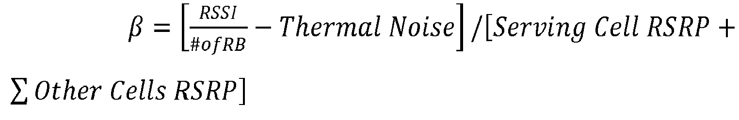
- the algorithm utilizes Eq. 3 below to measure the signal energy (1/ RSRQ ), as reported by the modem in dB; where, RSRP is the linear average of the power in Watts of all Resource Elements which carry cell-specific Reference Signals over the entire bandwidth.
- 1 RSRQ RSSI RSRP ⁇ # of RB
- the information on the number of DL RB may be calculated by the receiver LTE Channel Bandwidth [MHz] Max. Number of Resource Blocks Max. Occupied Bandwidth [MHz] 1.4 6 1.08 3 15 2.7 5 25 4.5 10 50 9.0 15 75 13.5 20 100 18.0 1
- FIG. 7 illustrates another example embodiment for calculating radio-link conditions as described herein. As shown, FIGs 7a and 7b may be utilized to estimate uplink congestion in LTE networks based at least from information extracted from the parameters of the base station 106.
- the information that may be sent via PHICH channel to all users by the base station 106 may be utilized in the measurements of the LTE UL congestion, where the PHICH is the Physical Hybrid-ARQ Indicator Channel (PHICH) in the downlink carries Hybrid ARQ (HARQ) acknowledgements (ACK/NACK) for uplink data transfers.
- PHICH Physical Hybrid-ARQ Indicator Channel
- HARQ Hybrid ARQ acknowledgements
- the users or network loading is estimated by filtering the Acknowledge (Ack) and not-acknowledge (Nack) transmissions from an empty group example (i.e., none) in a sampling group.
- the number of active users in a single PHICH group is proportional to the cell UL loading.
- the algorithm for the LTE networks may include calculation of the UL congestion in percentage according to histogram values correlated to maximum number of users per PHICH group. For example, to calculate the maximum number of users per PHICH group, the following are implemented. First, in network connected mode where all PHICH group is expected to contain Ack/Nack responses, the users' sequences in active PHICH group are decoded. Otherwise, in idle mode, the users' sequences in the PHICH group zero are decoded. Based on the decoded PHICH group, the number of valid users may then be calculated.
- the histogram is normalized to percentage according to the number of samples taken in the window. Afterwards, the maximum users per PHICH group may be measured or calculated.
- FIG. 7a illustrates a loaded group within the PHICH where the upper right portion of the figure represents the number of Nack transmissions while the lower left are the number of Ack transmissions.
- FIG. 7b illustrates presence of noise level in an empty group.
- the algorithm may apply"avoiding background traffic" option in the portable device 102. For example, this is done selectively for applications 106 that are bitrate hungry, while leaving foreground traffic and low bit-rate background traffic intact.
- identification of prolonged state of poor RF signal is implemented when: portable device 102 is located in poor RF and is stationary; or a watchdog timer is activated to eliminate the case for de-touching from background services. This timer may be zeroed once the portable device 102 is moving, based on mobility indicators.
- FIG. 8 shows an example process flowchart 800 illustrating an example method for improving power and performance in a portable device.
- the process flowchart 800 relates to the improvement of controlling background traffic for one or more device applications.
- the order in which the method is described is not intended to be construed as a limitation, and any number of the described method blocks may be combined in any order to implement the method, or alternate method. Additionally, individual blocks may be deleted from the method without departing from the spirit and scope of the subject matter described herein.
- the method may be implemented in any suitable hardware, software, firmware, or a combination thereof, without departing from the scope of the invention.
- the radio link - condition detector 210 is configured to perform an algorithm that identifies and measures different RF signal conditions and other congested radio link conditions.
- the radio link - condition detector 210 is a component of the portable device 102 that uses global system for mobile communications (GSM), a general packet radio services (GPRS), enhanced data rages for GSM evolution (EDGE), a 3G, or a 4G LTE, LTE-A system for data communications.
- GSM global system for mobile communications
- GPRS general packet radio services
- EDGE enhanced data rages for GSM evolution
- 3G 3G
- 4G LTE Long Term Evolution
- identification and measurements of the congestion amount may be based upon radio link conditions within the portable device 102 and/or the surrounding radio link conditions.
- comparing the measured congestion amount to a configured threshold level is performed.
- determining a level of congestion based from the measured congestion amount is performed.
- sending a notification in response to the determined level of congestion is performed.
- the notification includes a radio link condition alert to the user of the portable device 102.
- controlling a background traffic on selected one or more applications based upon the determined level of congestion is performed. For example, based from the measured congestion amount, the algorithm may implement behavior control of the background tasks in the portable device 102.
Landscapes
- Engineering & Computer Science (AREA)
- Computer Networks & Wireless Communication (AREA)
- Signal Processing (AREA)
- Mobile Radio Communication Systems (AREA)
Abstract
Description
- Wireless communication systems such as cellular networks are dimensioned to support growing traffic. As the traffic demands vary significantly, for example, during time of the day, day of the week, or a special event, it is not economical, and in some cases not feasible, to dimension the network to support the highest traffic demand. In these occurrences or cases, the network is congested, impacting users' ability to access the network for sending or receiving data, initiating phone calls or performing a particular service that is offered by users' mobile devices.
- The nature and severity of the congestion described above may vary from total blocking congestion as experienced in localized mass events, to short interruptions of service (e.g., drop calls), or to throttling of available bandwidth (BW). The present mechanisms that are implemented in the cellular network to optimize and balance the services during congestion state include traffic schedulers. However, present devices do not treat or are not aware of radio link congestion conditions. As such, there is a need to improve both power optimization and user experience of devices by overcoming the effects of congestion traffic.
-
-
FIG. 1 illustrates an example scenario that implements an optimization of one or more device applications' behavior to improve power and performance during data communication in a device. -
FIG. 2 is an example block diagram of a portable device that implements the embodiments described herein. -
FIG. 3 illustrates an overview table that shows a summary of congestion levels as described herein. -
FIGS. 4a and 4b illustrate an example embodiment of calculating radio-link conditions as described in present implementations herein. -
FIG. 5 illustrates an example of extracting physical (PHY) data from a modem as described in present implementations herein. -
FIG. 6 illustrates another example embodiment of calculating radio-link conditions as described herein. -
FIGS. 7a and 7b illustrates an example calculation of LTE Base-station downlink (DL) load, based on the energy measurement of Physical Hybrid-ARQ Indicator Channel (PHICH). -
FIG. 8 illustrates an exemplary process flowchart of an example method for improving power and performance in a portable device. - Described herein are technologies for identifying and measuring radio link conditions and thereafter, using the identified and measured radio link conditions to improve power consumption and performance in a device. For example, the radio link conditions may refer to a poor radio frequency (RF) signal and/or to other congested conditions due to device and/or network conditions. The identified and measured radio link conditions may be utilized by a portable or mobile device to control accordingly the behavior of one or more applications.
- In an implementation, the device may be configured to measure a congestion amount of the radio link conditions during downlink (DL) and/or uplink (UL) transmissions in the device. The measurement may be based from a type of network used by the portable device such as 3G, 4G, LTE network, as well as WiFi, etc. Furthermore, the measurement may be based from information that supplied by the device such as received signal strength indicator (RSSI), and parameters that may be extracted from a serving and/or neighboring base station. Furthermore, the measurements may be based upon a determined level of congestion such as a poor RF signal level, a soft congestion level, or a hard congestion level.
- For example, in the case of poor RF signal and soft congestion levels, the measurements of the congestion amount may be implemented separately for the DL and UL transmissions. However, for the hard congestion level, the measurement of the congestion amount may be implemented for both UL and the DL transmissions (i.e., not separate). In these cases, the measurements of the congestion amount per link are more efficient for purposes of improving the power and performance in the portable device.
- After obtaining the appropriate measured congestion amount as described above, the portable device may be configured to control accordingly the behavior of one or more applications that may be running in foreground or background tasks.
-
FIG. 1 is anexample scenario 100 that implements an optimization of one or more device applications' behavior to improve power and performance during data communication in a device. For example, the application's behavior is controlled based on present and existing radio link conditions such as poor radio frequency (RF) signal and/or congestion conditions within the device and/or in the network. Thescenario 100 shows aportable device 102 with anantenna 104, abase station 106, and awireless router 108 that facilitates data communication to anetwork 110. - In an implementation, the
portable device 102 may perform or process a background task such as a uploading to thenetwork 110 or downloading from thenetwork 110 during, for example, poor RF signal between theportable device 102 and thebase station 106. In this implementation, theportable device 102 may be configured to detect, measure, compare, and/or calculate the present and existing bidirectional radio link conditions within the portable device itself and/or surrounding cells or base stations during the background task process. The reason being, the radio link conditions such as the poor RF signal may affect UL or DL transmission operations in theportable device 102. - The present and existing radio link conditions may be derived from, but are not limited to, effects of co-running application(s), components, or features within the
portable device 102 as well as other devices, modem types such as 2G/3G/LTE-4G modems, overlapping cellular cells, effects ofnetwork 110 data, and the like. For a particular radio link condition (e.g., poor RF signal during the background task operation), theportable device 102 may be configured to implement an algorithm that may control the background traffic in the execution of one or more applications in theportable device 102. As further discussed below, the algorithm for the poor RF signal may utilize passive measurements of parameters from the portable device itself, measurements from thebase station 106, and measurements from a modem (not shown). In this manner, there is no need for theportable device 102 to be awakened or to benetwork 110 connected as what it does is simply to listen to the cell's broadcast messages and additional information, and measure the above parameters and to compare them with a pre-configured threshold value. The threshold value, for example, may facilitate determination of a good or a poor RF signal. - In an implementation, the algorithm may allow the application(s) with low-power requirements to run; however, the rest of the one or more "power-hungry" applications may be placed on hold until, for example, the
portable device 102 acquires a Wi-Fi connection from thewireless router 108. In this example, theportable device 102 does not waste its battery power by increasing power transmission given the low spectral efficiency due to the poor RF signals. In another case where the radio link condition amounts to a blocked cellular service (i.e., congested radio link condition), the algorithm may either stop execution of the one or more applications or trim down the amount of data and frequency of accessing thenetwork 110, rather than continuously trying to access thenetwork 110 to the inconvenience of a user. In the latter case, the algorithm may utilize a different set of variables as compared to the poor RF signal radio link condition. - The
base station 106 may not be limited to a single base-station as illustrated, and one ormore base stations 106 may cover or define a particular cellular cell or cells. Within the range of thebase station 106, theportable device 102 may communicate with another portable device (not shown) through thebase station 106. With the configuration of theportable device 102 as discussed above, the algorithm may minimize effects of the poor RF condition and other congestion condition, for example, during UL transmission in theportable device 102. As further discussed below, the algorithm may utilize information that may be extracted from parameters of thebase station 106. - The
portable device 102 may include, but is not limited to, a tablet computer, a netbook, a notebook computer, a laptop computer, mobile phone, a cellular phone, a smartphone, a personal digital assistant, a multimedia playback device, a digital music player, a digital video player, a navigational device, a digital camera, a machine and the like. Theportable device 102 further supports a broad array of cellular and wireless services over a very broad frequency range. For example, in addition to cellular services such as GSM, UMTS, or LTE, theportable device 102 may also offer Wi-Fi/WLAN, BT, and WiGig connectivity. - With continuing reference to
FIG. 1 , thewireless router 108 may include a device that facilitates wireless connection between the portable 102 and a wired Ethernet connection. For example, thewireless router 108 may include a Wi-Fi router that provides a hotspot in a particular place. In this example, the Wi-Fi router may receive data signals from the portable device 102 (during UL data communication) and sends the received data signals to Internet using a physical, wired Ethernet connection. Similarly, the Wi-Fi router may communicate data to the portable device 102 (during DL data communication) using the wireless connection between the two. The embodiments described inFIG. 1 are not limited to thewireless router 108 but may also include other form of wireless communications services that may be utilized by theportable device 102 during the poor RF signal or congested radio link condition. -
FIG. 2 is an example block diagram of aportable device 102 that may implement the embodiments described herein. Theportable device 102 may include a control processing unit (CPU) 202, amemory device 204, one ormore applications 206 that may be stored in astorage 208, a radio link -condition detector 210, amodem 212, and adisplay device 214. In certain implementations, the radio link -condition detector 210 is part of themodem 212. - As discussed above, the
portable device 102 utilizes the radio link conditions to measure the current RF signal and/or congestion levels that may affect the UL and DL transmissions in the portable device. As described herein, a passive identification of the radio link conditions may result to a 1) poor RF condition; 2) soft congestion; and 3) hard congestion or blocking condition. For the first two radio conditions (i.e., poor RF condition and the soft congestion), the algorithm may separately perform measurements or identification of parameters for the UL and DL transmissions. However, for the hard congestion condition, the algorithm may utilize both UL and DL transmissions. - The passive identification may not require an active connection to the
network 110 and as such, the passive identification process may require a lower power implementation. In other words, there is no need to awaken the operating system (OS) for the passive identification to be implemented. However, the user may be alerted of the existence of extreme conditions for manual control, for example, of background traffic of selected background tasks or applications. - In certain implementations, the control processing unit (CPU) 202 and OS are provided by an entity, and the
modem 212 is provided by a different entity. It is to be understood that the various described components and systems may be grouped or provided by different entities, and integrated with another on a device. - With continuing reference to
FIG. 2 , theportable device 102 may include theCPU 202 that may be configured to execute stored instructions, as well as thememory device 204 that stores instructions, which are executable by theCPU 202. TheCPU 202 may control and coordinate the overall operations of theportable device 102. Furthermore, theCPU 202 may be a single core processor, a multi-core processor, a computing cluster, or any number of other configurations. - In an implementation, the
memory device 204 may include a main memory of theportable device 102. In addition, thememory device 204 may include any form of random access memory (RAM), read-only memory (ROM), flash memory, or the like. For example, thememory device 204 may be one or more banks of memory chips or integrated circuits. In this example, theCPU 202 may have direct access to thememory device 204 through a bus connection (not shown). - The instructions that are executed by the
CPU 202 may be used to execute any of a number ofapplications 206 residing within thestorage device 208 of theportable device 102. Theapplications 206 may be any types of applications or programs having graphics, sounds, graphics images, or the like, to be displayed to a user (not shown) through thedisplay device 214. Thestorage device 208 may include a hard drive, an optical drive, a thumb drive, an array of drives, or any combinations thereof. - In an implementation, the radio link -
condition detector 210 may include a processor, firmware, hardware, software or a combination thereof to identify and measure the surrounding radio link conditions (i.e., poor RF signal and/or congested network) and to facilitate the controlling of behavior of background or foreground tasks (i.e., applications 206) for power optimization and high throughput during data communication. That is, the radio link -condition detector 210 may implement the controlling of the background traffic for selected one or more applications based from the measured present and existing radio link conditions. As discussed above, the radio link -condition detector 210 may be part ofmodem 212. - For example, the radio link -
condition detector 210 may be configured to implement and perform the algorithm as generally described above. In this example, the radio link -condition detector 210 may first determine whether the present and existing radio link condition includes the poor RF condition, the soft congestion or the hard congestion (blocking condition). With this determination, the algorithm may facilitate measurements of parameters within theportable device 102 such as the parameters supplied by themodem 212, and/or parameters that may be extracted from thebase station 106. In such a case, the radio link conditions during DL and UL modes are considered for purposes of adjusting the foreground and background tasks that are currently running in theportable device 102. For example, the algorithm may further facilitate dynamic control of the running of power-hungry applications depending upon the varying congestion level measurements during the UL and/or DL transmissions. -
FIG. 3 illustrates an overview table 300 that enumerates a summary of congestion levels as described herein. For example, as described in the functions of radio link -condition detector 210 above, the table 300 may enumerate the passively identified radio link conditions together with its corresponding effects and action(s) required for these effects. For purposes of illustration, the table 300 includes the following columns: acongestion level 302, an identification ofmetrics 304, an impact on theportable device 306; and effects on the application'sbehavior 308. - For example, the DL congestion for soft inaccessibility (shown in column 302) may be identified by the algorithm through passive measurements and/or previously allocated DL resources (shown in column 304). In this example, the impact on the
portable device 102 includes slow and intermittent DL traffic (column 306) while the change of behavior for this congestion level includes, for example, a delay background traffic (shown in column 308). - In another example, the UL congestion for soft inaccessibility (shown in column 302) may be identified through UL noise rise measurements, previously allocated UL resources or, if successful, physical Random Access Channel (pRACH) process duration (shown in column 304). In this example, the impact on the
portable device 102 includes slow and intermittent DL traffic (column 306) while the change of behavior for this congestion level includes, for example, a delay in uploading large files (shown in column 308). - In another example still, the hard inaccessibility indicator (shown in column 302) may be identified, for example, through pRACH process failure, access class barring, or RRM failure (shown in column 304). In this example, the impact on the
portable device 102 includes lack of access or repeated failure to connect (column 306) while the change of behavior for this congestion level includes, for example, avoid initiating sessions during barring period to save power (shown in column 308). -
FIGS. 4(a) and 4(b) illustrate an example embodiment of calculating radio-link conditions as described in present implementations herein. The equations, formulas, measurement parameters, etc. as further discussed below may be implemented by the radio link -condition detector 210 through the algorithm as described herein. -
FIG. 4(a) illustrates an equation that may be utilized to determine the amount of transmitting power that theportable device 102 is currently using to perform, for example, network loading or network downloading. Based from determined amount of transmitting power, the effect(s), for example, of the poor RF signal in theportable device 102 during 3G data communications may be determined. - For example, if a calculated amount of initial transmission power (Tx init-calculated 400) in the
portable device 102 during the 3G data communication is above the pre-configured threshold level, then a flag (not shown) that represents presence of "poor RF signal" may be activated. Otherwise, the UL transmission in theportable device 102 may continue its normal operations because the presence of "poor RF signal" does not affect at all its regular transmission operations. In this example, the threshold level may include a parameter amount or value that generally distinguishes a good radio link condition from a poor radio link condition. - With continued reference to
FIG. 4(a) , the measurement of theTx init-calculated 400 in 3G networks may be performed in passive mode. That is, theportable device 102 needs only to observe the parameters or variables contained in the equation without being connected to any network, such as thenetwork 110. In this implementation, theTx init-calculated 400 may be based upon the following variables:P TX-CPICH 402 that is a parameter received by the system information blocks (SIB) of theportable device 102 from thebase station 106;RSCP CPICH 404 that is a parameter that is measured from themodem 212;UL interference 406 that is a measurement received from thebase station 106; and constant variable 408 (i.e., "27"). As can be observed from the equation, theTx init-calculated 400 is based from radio link conditions or information within theportable device 102 and also from the radio link conditions that may be extracted from the parameters of thebase station 106. -
FIG. 4(b) illustrates the measurements of the initial transmission power (Tx init-calculated_LTE 410) in theportable device 102 for the LTE networks. As shown, theTx init-calcitlated_LTE 410 may be based upon the following variables:LTE_InitialReceivedTargetPower 412; and Path Loss (PL) 414 where thePL 414 is equal to the difference between theLTE_referenceSignalPower 416 and theLTE_RSRP 418 variables. - With the obtained
Tx init-calculated 400 andTx init-calcitlated_LTE 410 for 3G and LTE networks, respectively, the algorithm may be configured to control the device applications' behavior as described herein. -
FIG. 5 an embodiment of extracting physical (PHY) data from a modem as described in present implementations herein. In this embodiment, the algorithm may separately treat the DL radio link conditions from the UL radio link conditions. For example, when more than one portable device accesses thebase station 106, each of these other portable devices may provide an additional noise to one another or to the system. To this end, the algorithm may be configured to calculate and measure the amount of congestion traffic during DL and/or UL transmissions such as in the 3G or LTE system - To calculate the DL congestion in the 3G network, a signal energy per chip ( Ec / Io ) 500 may represent the DL congestion traffic that may be measured in the receiver
portable device 102. With the measured Ec / Io 500, a parameter (i.e., γDL ) is calculated and normalized to provide the measured relative load parameter of the serving base station (e.g., base station 106). In this example, the algorithm may improve accuracy of DL congestion modelling by using additional information obtained from the modem 212 (e.g., RSCP and RSSI) and UL congestion indications (i.e., neighboring cellular cell measurements). - In an implementation, the algorithm utilizes Eq. 1 below to measure the Ec / I0 500 in dB:

- With this Ec / Io 500 measurements, a normalized DL congestion indicator (γDL ) may be calculated, defined and normalized to include zero to 100% value where the (γ DL ) may be calculated in Eq. 2 below.

- Based from the derived value of the γDL in Eq. 2, the following congestion level conditions may be derived: 1) low congestion may be defined by 25% > γDL ≥ 0%; 2) medium congestion may be defined by 50% > γDL ≥ 25%; and 3) high congestion is defined by γDL ≥ 50%. With these congestion levels, the algorithm may implement the necessary control of the background tasks as appropriate.
- In another implementation such as the extraction of the γDL from a modem data, the Ec / Io 500 is first calculated and based from the calculated value and the following assumptions, the ratio below is computed.

- The assumptions in the approximation of the γDL includes: 1) that the neighboring cellular cells have similar loads compared to the service cell (i.e., base station 106); 2) that the paging channels overhead is 30% of the CPICH power; and 3) that the nominal CPICH power ratio is 2-5% of maximal cell transmission power as further discussed in β Max equation below. CPICH is common pilot channel.
- Going back to the Ec / Io 500, the following assumption is further considered (i.e., values are in watts):


- Assuming that ratio β is measured as:

- Also, assuming that the ratio β is identical for all cellular cells (i.e., this is not correct; however, the error is limited), then the assumption below takes place.

- With the assumption that the ratio β is identical for all cellular cells, ratio β may be computed as:

- Assuming further that CPICH Tx Power is 2÷5% of
maximal base station 106 Tx power (βMax = 20 ÷ 50), and that the Paging Channels overhead is ∼30% of the CPICH power, then the following may be derived:
- As an example, for β Max = 20, the following equation is determined, 5.35 · β - 6.95.
- As another example, for βMax = 25, the following equation is determined, 4.22 · β - 5.48.
- As the calculations above are approximate, the γ DL may have either negative or over 100% values which may be truncated accordingly. Furthermore, all power levels in the above equations are in watts (not dBm). Furthermore still, the accuracy of the CPICH power level that is reported by the
base station 106 in SIB when divided by the maximal Tx power (i.e., 40watts) is:
-
FIG. 6 illustrates another example embodiment for calculating radio-link conditions as described herein. As shown, the equation may be utilized to estimate uplink congestion in 3G based at least from an information extracted from the parameters of thebase station 106. - For the 3G networks, a report of received noise level by the
base station 106 may be utilized to map its uplink load. For example, as shown in table below, the normalized UL congestion indicator (γ UL ) may include different values (e.g., 0%, 20%, etc.) that corresponds with different values of UL noise rise 600 (i.e., in dB). The UL noise rise 600, for example, may be based from the following parameters: "UL noise level report" 602 and "minimal value reported for the cell" 604. In another example, the UL noise rise 600 may be approximated to include the difference between the "UL noise level report" 602 and negative 103dB. The equation inFIG. 6 is repeated below for purposes of illustration.
- With the derived amount or value of the UL noise rise 600, the table below may be utilized to derive the corresponding normalized UL congestion indicator (γ UL ) 502.
UL Noise Rise in dB γ UL Congestion Indicator 0 to 1 0% 2 to 4 20% 5 to 7 40% 8 to 11 60% 12 to 15 80% 16 or above 100% - To calculate the DL congestion in the LTE network, a signal energy per chip (1/RSRQ) may represent the DL congestion traffic that may be measured in the receiver portable device. With the measured (1/RSRQ), a parameter (i.e., β) is calculated and normalized to provide the measured relative load parameter of the serving base station. In this example, the algorithm may improve accuracy of DL congestion modelling by using additional information obtained from the modem (e.g., RSRP and RSSI).
- For example, the congestion amount in a 3G/4G DL transmission may include a calculation of a base-station load based on PHY measurements,
- RSSI, Ec / Io for 3G, RSCP, RSCQ for 4G and an impact of neighboring cellular base-stations.
- In an implementation, the algorithm utilizes Eq. 3 below to measure the signal energy (1/RSRQ), as reported by the modem in dB; where, RSRP is the linear average of the power in Watts of all Resource Elements which carry cell-specific Reference Signals over the entire bandwidth.

- The information on the number of DL RB may be calculated by the receiver
LTE Channel Bandwidth [MHz] Max. Number of Resource Blocks Max. Occupied Bandwidth [MHz] 1.4 6 1.08 3 15 2.7 5 25 4.5 10 50 9.0 15 75 13.5 20 100 18.0 


- where

-
FIG. 7 illustrates another example embodiment for calculating radio-link conditions as described herein. As shown,FIGs 7a and 7b may be utilized to estimate uplink congestion in LTE networks based at least from information extracted from the parameters of thebase station 106. - In LTE networks, there is no UL interference report. However, an approximation of number users in the network loading may be utilized by the algorithm to implement control of the one or more applications' behavior.
- For example, the information that may be sent via PHICH channel to all users by the
base station 106 may be utilized in the measurements of the LTE UL congestion, where the PHICH is the Physical Hybrid-ARQ Indicator Channel (PHICH) in the downlink carries Hybrid ARQ (HARQ) acknowledgements (ACK/NACK) for uplink data transfers. For example, the users or network loading is estimated by filtering the Acknowledge (Ack) and not-acknowledge (Nack) transmissions from an empty group example (i.e., none) in a sampling group. In this example, the number of active users in a single PHICH group is proportional to the cell UL loading. - In an implementation, the algorithm for the LTE networks may include calculation of the UL congestion in percentage according to histogram values correlated to maximum number of users per PHICH group. For example, to calculate the maximum number of users per PHICH group, the following are implemented. First, in network connected mode where all PHICH group is expected to contain Ack/Nack responses, the users' sequences in active PHICH group are decoded. Otherwise, in idle mode, the users' sequences in the PHICH group zero are decoded. Based on the decoded PHICH group, the number of valid users may then be calculated.
- With the calculated number of valid users, these are accumulated to a valid user count histogram (i.e., not sorted by sub-frame or PHICH group). Per measuring window of window of 1∼5 seconds, the histogram is normalized to percentage according to the number of samples taken in the window. Afterwards, the maximum users per PHICH group may be measured or calculated.
- With continuing reference to
FIG. 7, FIG. 7a illustrates a loaded group within the PHICH where the upper right portion of the figure represents the number of Nack transmissions while the lower left are the number of Ack transmissions. On the other hand,FIG. 7b illustrates presence of noise level in an empty group. - Once the conditions in the discussion above are identified, the algorithm may apply"avoiding background traffic" option in the
portable device 102. For example, this is done selectively forapplications 106 that are bitrate hungry, while leaving foreground traffic and low bit-rate background traffic intact. In this example, identification of prolonged state of poor RF signal is implemented when:portable device 102 is located in poor RF and is stationary; or a watchdog timer is activated to eliminate the case for de-touching from background services. This timer may be zeroed once theportable device 102 is moving, based on mobility indicators. -
FIG. 8 shows anexample process flowchart 800 illustrating an example method for improving power and performance in a portable device. For example, theprocess flowchart 800 relates to the improvement of controlling background traffic for one or more device applications. The order in which the method is described is not intended to be construed as a limitation, and any number of the described method blocks may be combined in any order to implement the method, or alternate method. Additionally, individual blocks may be deleted from the method without departing from the spirit and scope of the subject matter described herein. Furthermore, the method may be implemented in any suitable hardware, software, firmware, or a combination thereof, without departing from the scope of the invention. - At
block 802, measuring a congestion amount based upon radio link conditions that include an UL or a DL transmission is performed. For example, the radio link -condition detector 210 is configured to perform an algorithm that identifies and measures different RF signal conditions and other congested radio link conditions. The radio link -condition detector 210 is a component of theportable device 102 that uses global system for mobile communications (GSM), a general packet radio services (GPRS), enhanced data rages for GSM evolution (EDGE), a 3G, or a 4G LTE, LTE-A system for data communications. - As discussed above, identification and measurements of the congestion amount may be based upon radio link conditions within the
portable device 102 and/or the surrounding radio link conditions. - At block 804, comparing the measured congestion amount to a configured threshold level is performed.
- At
block 806, determining a level of congestion based from the measured congestion amount is performed. - At
block 808, sending a notification in response to the determined level of congestion is performed. For example, the notification includes a radio link condition alert to the user of theportable device 102. - At
block 810, controlling a background traffic on selected one or more applications based upon the determined level of congestion is performed. For example, based from the measured congestion amount, the algorithm may implement behavior control of the background tasks in theportable device 102. - The following examples pertain to further embodiments:
- Example 1 is a method of improving power consumption and performance in a device, the method comprising: measuring a congestion amount based upon radio link condition that include an uplink (UL) or a downlink (DL) transmission; comparing the measured congestion amount to a threshold level; determining a level of congestion based on the measured congestion amount; and controlling a background traffic on selected one or more applications based on the determined level of congestion.
- In example 2, the method as recited in example 1, wherein the level of congestion is based on one or more of a poor radio frequency (RF) signal level, a soft congestion level, or a hard congestion level.
- In example 3, the method as recited in example 2, wherein the measurement of the congestion amount for the poor RF signal is implemented separately for the UL and the DL transmissions.
- In example 4, the method as recited in example 2, wherein the measurement of the congestion amount for the soft congestion level is implemented separately for the UL and the DL transmissions.
- In example 5, the method as recited in example 2, wherein the calculation of a 3G UL transmission includes a utilization of system information blocks (SIB) information of a base-station UL noise level to determine a UL load in the device.
- In example 6, the method as recited in example 2, wherein the calculation of a LTE UL transmission is based PHICH channel logging and measurement.
- In example 7, the method as recited in example 2, wherein the measurement of the congestion amount for the hard congestion level is implemented for both UL and the DL transmissions.
- In example 8, the method as recited in example 1, wherein the measurement of the congestion amount in a 3G DL transmission includes a calculation of a base-station load based on PHY measurements, RSSI, Ec / Io , and an impact of other neighboring base-stations.
- In example 9, the method as recited in example 8, wherein the measurement of the congestion amount of the 3G DL transmission further includes a utilization of system information blocks (SIB) information, which uses a common pilot channel (CPICH) power as a variable to improve calculation accuracy.
- In example 10, the method as recited in example 1, wherein the measurement of the congestion amount in a LTE-4G DL transmission includes a calculation of a base-station load based on PHY measurements, RSSI, RSRP, RSRQ, an impact of other neighboring cellular base-stations, and an impact of a network data.
- In example 11, the method as recited in example 10, wherein the measurement of the congestion amount of the LTE-4G DL transmission further includes a utilization of a system information blocks (SIB) information, which uses a reference symbols power and bandwidth to improve calculation accuracy.
- In example 12, the method as recited in any of examples 1 to 11, wherein the measuring of the congestion amount is device agnostic and performed during data communication, wherein the data communication implements one or more of a global system for mobile communications (GSM), a general packet radio services (GPRS), enhanced data rages for GSM evolution (EDGE), a 3G, or an LTE-4G system.
- In example 13, the method as recited in any of examples 1 to 11, wherein the controlling the background traffic is based upon a measured transmission power to run background tasks or applications.
- Example 14 is a device comprising: one or more processors; a radio link-condition detector component coupled to the one or more processors and configured to detect and measure one or more radio link condition parameters, and utilize the one or more measured radio link condition parameters to control a background traffic on selected one or more applications.
- In example 15, the device as recited in example 14, wherein the measured radio link condition parameters provides different level of congestions that include: a poor radio frequency (RF) signal level, a soft congestion level, or a hard congestion level.
- In example 16, the device as recited in example 15, wherein the measurement of the radio link conditions for the poor RF signal is implemented separately for an uplink (UL) and downlink (DL) transmissions.
- In example 17, the device as recited in any of examples 14 to 16, wherein the radio link-condition detector component is further configured to compare the measured radio link condition parameters to a threshold value.
- In example 18, the device as recited in any of examples 14 to 16, wherein the measured radio link condition parameters include a calculated transmitting power during a poor radio frequency (RF) signal condition, wherein the controlling of the background traffic is implemented for the calculated transmitting power that is above the threshold value.
- Example 19 is a method of controlling an application's behavior in a device, the method comprising: measuring a congestion amount based on radio link condition; comparing the measured congestion amount to a threshold level; and controlling a background traffic on selected one or more applications based on the comparison between the measured congestion amount and the threshold level.
- In example 20, the method as recited in example 19, wherein the measurement of the congestion amount in a LTE-4G DL transmission includes a calculation of a base-station load based on PHY measurements, RSSI, RSRP, RSRQ, an impact of a neighboring cellular base-stations, and an impact of a network data.
- In example 21, the method as recited in example 20, wherein the measurement of the congestion amount of the LTE-4G DL transmission further includes a utilization of a system information blocks (SIB) information, which uses a reference symbols power and bandwidth to improve calculation accuracy.
Claims (15)
- A method of improving power consumption and performance in a device, the method comprising:measuring a congestion amount based upon radio link condition that include an uplink (UL) or a downlink (DL) transmission;comparing the measured congestion amount to a threshold level;determining a level of congestion based on the measured congestion amount; andcontrolling a background traffic on selected one or more applications based on the determined level of congestion.
- The method as recited in claim 1, wherein the measuring of the congestion amount is device agnostic and performed during data communication, wherein the data communication implements one or more of a global system for mobile communications (GSM), a general packet radio services (GPRS), enhanced data rages for GSM evolution (EDGE), a 3G, or an LTE-4G system.
- The method as recited in claim 1, wherein the level of congestion is based on one or more of a poor radio frequency (RF) signal level, a soft congestion level, or a hard congestion level.
- The method as recited in claim 3, wherein the measurement of the congestion amount for the poor RF signal is implemented separately for the UL and the DL transmissions.
- The method as recited in claim 3, wherein the measurement of the congestion amount for the soft congestion level is implemented separately for the UL and the DL transmissions.
- The method as recited in claim 3, wherein the measurement of the congestion amount for the hard congestion level is implemented for both UL and the DL transmissions.
- The method as recited in claim 1, wherein the measurement of the congestion amount in a 3G DL transmission includes a calculation of a base-station load based on PHY measurements, RSSI, Ec / Io , and an impact of other neighboring base-stations.
- The method as recited in claim 7, wherein the measurement of the congestion amount of the 3G DL transmission further includes a utilization of system information blocks (SIB) information, which uses a common pilot channel (CPICH) power as a variable to improve calculation accuracy.
- The method as recited in claim 1, wherein the measurement of the congestion amount in a LTE-4G DL transmission includes a calculation of a base-station load based on PHY measurements, RSSI, RSRP, RSRQ, an impact of other neighboring cellular base-stations, and an impact of a network data.
- The method as recited in claim 9, wherein the measurement of the congestion amount of the LTE-4G DL transmission further includes a utilization of a system information blocks (SIB) information, which uses a reference symbols power and bandwidth to improve calculation accuracy.
- The method as recited in claim 3, wherein the calculation of a 3G UL transmission includes a utilization of system information blocks (SIB) information of a base-station UL noise level to determine a UL load in the device.
- The method as recited in claim 3, wherein the calculation of a LTE UL transmission is based PHICH channel logging and measurement.
- The method as recited in claim 1, wherein the controlling the background traffic is based upon a measured transmission power to run background tasks or applications.
- A device comprising:one or more processors;a radio link-condition detector component coupled to the one or more processors and configured to detect and measure one or more radio link condition parameters, and utilize the one or more measured radio link condition parameters to control a background traffic on selected one or more applications.
- The device as recited in claim 14, wherein the radio link-condition detector component is further configured to compare the measured radio link condition parameters to a threshold value.
Applications Claiming Priority (1)
| Application Number | Priority Date | Filing Date | Title |
|---|---|---|---|
| US14/671,994 US10588049B2 (en) | 2015-03-27 | 2015-03-27 | Optimizing applications behavior in a device for power and performance |
Publications (1)
| Publication Number | Publication Date |
|---|---|
| EP3073689A1 true EP3073689A1 (en) | 2016-09-28 |
Family
ID=55456617
Family Applications (1)
| Application Number | Title | Priority Date | Filing Date |
|---|---|---|---|
| EP16157753.1A Withdrawn EP3073689A1 (en) | 2015-03-27 | 2016-02-26 | Optimizing applications behaviour in a device for power and performance |
Country Status (4)
| Country | Link |
|---|---|
| US (1) | US10588049B2 (en) |
| EP (1) | EP3073689A1 (en) |
| CN (1) | CN106028399B (en) |
| TW (1) | TWI620450B (en) |
Families Citing this family (3)
| Publication number | Priority date | Publication date | Assignee | Title |
|---|---|---|---|---|
| US10749639B2 (en) * | 2017-01-24 | 2020-08-18 | Mediatek Inc. | Bearer switching in reduced radio link quality conditions |
| US10972358B2 (en) | 2017-08-30 | 2021-04-06 | Citrix Systems, Inc. | Inferring congestion and signal quality |
| CN111417145B (en) * | 2019-01-04 | 2021-11-30 | 大唐移动通信设备有限公司 | Information processing method and device |
Citations (4)
| Publication number | Priority date | Publication date | Assignee | Title |
|---|---|---|---|---|
| US20130121147A1 (en) * | 2011-11-14 | 2013-05-16 | T-Mobile USA, Inc | Controlling Uplink Congestion in a Wireless Communication Network |
| US20140092734A1 (en) * | 2012-03-30 | 2014-04-03 | Sony Mobile Communications Ab | Network-controlled adaptive terminal behavior managing high-network-load scenarios |
| US20140113616A1 (en) * | 2012-10-19 | 2014-04-24 | Sony Mobile Communications Ab | Network initiated terminal background activity control |
| US20140146681A1 (en) * | 2012-11-27 | 2014-05-29 | At&T Mobility Ii Llc | Detection and prevention of heavy congestion in a wireless network |
Family Cites Families (15)
| Publication number | Priority date | Publication date | Assignee | Title |
|---|---|---|---|---|
| US8755270B2 (en) * | 2007-02-05 | 2014-06-17 | Telefonaktiebolaget L M Ericsson (Publ) | Congestion/load indication for high speed packet access |
| WO2011038881A1 (en) * | 2009-09-29 | 2011-04-07 | Nec Europe Ltd. | Method for performing communication in a self-organized wireless network |
| US8953522B2 (en) * | 2010-03-29 | 2015-02-10 | Samsung Electronics Co., Ltd. | Method and apparatus for controlling retransmission on uplink in a wireless communication system supporting MIMO |
| WO2011138351A1 (en) * | 2010-05-06 | 2011-11-10 | Koninklijke Kpn N.V. | Method and telecommunications infrastructure for activating an inactive cell |
| US8488461B2 (en) * | 2010-05-12 | 2013-07-16 | The Chinese University Of Hong Kong | Adaptive scheduling of data transfer in P2P applications over asymmetric networks |
| US9167618B2 (en) * | 2010-11-16 | 2015-10-20 | At&T Mobility Ii Llc | Data bundling and fast dormancy based upon intelligent application learning |
| US9264868B2 (en) * | 2011-01-19 | 2016-02-16 | Qualcomm Incorporated | Management of network access requests |
| US9439061B2 (en) * | 2011-05-27 | 2016-09-06 | At&T Mobility Ii Llc | Selective prioritization of voice over data |
| WO2013170226A1 (en) * | 2012-05-10 | 2013-11-14 | Eden Rock Communications, Llc | Method and system for auditing and correcting cellular antenna coverage patterns |
| US9585054B2 (en) * | 2012-07-19 | 2017-02-28 | Interdigital Patent Holdings, Inc. | Method and apparatus for detecting and managing user plane congestion |
| CN108282802B (en) * | 2012-09-04 | 2021-05-11 | 中兴通讯股份有限公司 | Base station, terminal and power control method thereof |
| US9277444B2 (en) * | 2013-12-17 | 2016-03-01 | Verizon Patent And Licensing Inc. | Restriction of background application data during congestion |
| US20150208276A1 (en) * | 2014-01-20 | 2015-07-23 | Vodafone Ip Licensing Limited | Congestion detection |
| US20160080991A1 (en) * | 2014-09-15 | 2016-03-17 | Nokia Solutions And Networks Oy | GERAN Frequency Based Insight Delivery To Mobile Devices |
| US11382080B2 (en) * | 2015-01-09 | 2022-07-05 | Apple Inc. | System information signaling for link budget limited wireless devices |
-
2015
- 2015-03-27 US US14/671,994 patent/US10588049B2/en not_active Expired - Fee Related
-
2016
- 2016-02-25 TW TW105105649A patent/TWI620450B/en not_active IP Right Cessation
- 2016-02-26 CN CN201610109788.9A patent/CN106028399B/en not_active Expired - Fee Related
- 2016-02-26 EP EP16157753.1A patent/EP3073689A1/en not_active Withdrawn
Patent Citations (4)
| Publication number | Priority date | Publication date | Assignee | Title |
|---|---|---|---|---|
| US20130121147A1 (en) * | 2011-11-14 | 2013-05-16 | T-Mobile USA, Inc | Controlling Uplink Congestion in a Wireless Communication Network |
| US20140092734A1 (en) * | 2012-03-30 | 2014-04-03 | Sony Mobile Communications Ab | Network-controlled adaptive terminal behavior managing high-network-load scenarios |
| US20140113616A1 (en) * | 2012-10-19 | 2014-04-24 | Sony Mobile Communications Ab | Network initiated terminal background activity control |
| US20140146681A1 (en) * | 2012-11-27 | 2014-05-29 | At&T Mobility Ii Llc | Detection and prevention of heavy congestion in a wireless network |
Also Published As
| Publication number | Publication date |
|---|---|
| TWI620450B (en) | 2018-04-01 |
| CN106028399A (en) | 2016-10-12 |
| TW201644294A (en) | 2016-12-16 |
| US20160286430A1 (en) | 2016-09-29 |
| CN106028399B (en) | 2020-06-05 |
| US10588049B2 (en) | 2020-03-10 |
Similar Documents
| Publication | Publication Date | Title |
|---|---|---|
| EP3295718B1 (en) | Cell selection procedures for machine type communication devices supporting coverage enhancement | |
| EP2815604B1 (en) | Methods and devices for adjusting resource management procedures in heterogeneous communication networks | |
| US9307436B2 (en) | Method and user equipment for user equipment to report a measurement result | |
| EP2667654B1 (en) | Uplink power detection method, device and base station equipment | |
| US10021574B2 (en) | Spectrum sharing method and apparatus | |
| EP2102676B1 (en) | Improved load estimation for a cell in a wireless network | |
| US20120252432A1 (en) | Method, apparatus and computer program product for obtaining deactivated secondary cell measurements while a mobile terminal is in motion | |
| US10187881B2 (en) | Uplink power control method and apparatus | |
| EP3200513B1 (en) | User device, base station, uplink transmission power reporting method, and parameter notification method | |
| US9271223B2 (en) | Adaptive filtering of cell measurements | |
| CN115087034A (en) | System selection for high throughput wireless communication | |
| US9220126B2 (en) | Method and apparatus for user equipment control in a cellular network | |
| EP3200502B1 (en) | User device, base station, and uplink transmission power reporting method | |
| US20140171086A1 (en) | Mobile station and mobile communication method | |
| US20140112172A1 (en) | Load Estimation in 3GPP Networks | |
| EP2991404A1 (en) | Mitigating interference with wireless communications | |
| US9456392B2 (en) | Mobile station and communication method | |
| EP3073689A1 (en) | Optimizing applications behaviour in a device for power and performance | |
| US20230269614A1 (en) | Measurement adjustment method and terminal | |
| EP3754864A1 (en) | User device | |
| EP2892265A1 (en) | Method, device and system for processing communication service | |
| US20140274068A1 (en) | Mobile terminal and method for determining a receive window | |
| US9961603B2 (en) | Radio base station | |
| GB2493290A (en) | Forming a common relative grant channel monitoring set of neighbour cells up to an upper limit of neighbour cells | |
| US10547533B2 (en) | Service distribution obtaining method, apparatus, and system |
Legal Events
| Date | Code | Title | Description |
|---|---|---|---|
| PUAI | Public reference made under article 153(3) epc to a published international application that has entered the european phase |
Free format text: ORIGINAL CODE: 0009012 |
|
| 17P | Request for examination filed |
Effective date: 20160226 |
|
| AK | Designated contracting states |
Kind code of ref document: A1 Designated state(s): AL AT BE BG CH CY CZ DE DK EE ES FI FR GB GR HR HU IE IS IT LI LT LU LV MC MK MT NL NO PL PT RO RS SE SI SK SM TR |
|
| AX | Request for extension of the european patent |
Extension state: BA ME |
|
| RIN1 | Information on inventor provided before grant (corrected) |
Inventor name: KREUCHAUF, JUERGEN H Inventor name: TAVOR, EREZ Inventor name: RAMON, ROY Inventor name: WEISMAN, OLGA Inventor name: ABIRI, RONI Inventor name: ZAFRIR, OFER ZAF Inventor name: RAVGAD, SEGEV |
|
| RIN1 | Information on inventor provided before grant (corrected) |
Inventor name: ABIRI, RONI Inventor name: ZAFRIR, OFER ZAF Inventor name: RAVGAD, SEGEV Inventor name: RAMON, ROY Inventor name: TAVOR, EREZ Inventor name: WEISMAN, OLGA Inventor name: KREUCHAUF, JUERGEN H |
|
| 17Q | First examination report despatched |
Effective date: 20170316 |
|
| STAA | Information on the status of an ep patent application or granted ep patent |
Free format text: STATUS: THE APPLICATION IS DEEMED TO BE WITHDRAWN |
|
| 18D | Application deemed to be withdrawn |
Effective date: 20180907 |