EP3073479A1 - Digital display - Google Patents
Digital display Download PDFInfo
- Publication number
- EP3073479A1 EP3073479A1 EP15275089.9A EP15275089A EP3073479A1 EP 3073479 A1 EP3073479 A1 EP 3073479A1 EP 15275089 A EP15275089 A EP 15275089A EP 3073479 A1 EP3073479 A1 EP 3073479A1
- Authority
- EP
- European Patent Office
- Prior art keywords
- pixel
- update
- illuminated
- store
- period
- Prior art date
- Legal status (The legal status is an assumption and is not a legal conclusion. Google has not performed a legal analysis and makes no representation as to the accuracy of the status listed.)
- Ceased
Links
- 238000000034 method Methods 0.000 claims abstract description 31
- 230000004044 response Effects 0.000 claims abstract description 10
- 238000005286 illumination Methods 0.000 claims description 37
- 230000008447 perception Effects 0.000 claims description 7
- 238000012545 processing Methods 0.000 description 28
- 230000015654 memory Effects 0.000 description 21
- 238000012546 transfer Methods 0.000 description 15
- 230000006870 function Effects 0.000 description 11
- 230000008569 process Effects 0.000 description 8
- 238000013459 approach Methods 0.000 description 5
- 230000001960 triggered effect Effects 0.000 description 5
- 239000004973 liquid crystal related substance Substances 0.000 description 4
- 238000010586 diagram Methods 0.000 description 3
- 230000008859 change Effects 0.000 description 2
- 238000012937 correction Methods 0.000 description 2
- 238000012986 modification Methods 0.000 description 2
- 230000004048 modification Effects 0.000 description 2
- XUIMIQQOPSSXEZ-UHFFFAOYSA-N Silicon Chemical compound [Si] XUIMIQQOPSSXEZ-UHFFFAOYSA-N 0.000 description 1
- 238000007792 addition Methods 0.000 description 1
- 230000008901 benefit Effects 0.000 description 1
- 230000003139 buffering effect Effects 0.000 description 1
- 238000006243 chemical reaction Methods 0.000 description 1
- 238000007796 conventional method Methods 0.000 description 1
- 238000013500 data storage Methods 0.000 description 1
- 230000001419 dependent effect Effects 0.000 description 1
- 230000009977 dual effect Effects 0.000 description 1
- 230000000694 effects Effects 0.000 description 1
- 238000011016 integrity testing Methods 0.000 description 1
- 238000007726 management method Methods 0.000 description 1
- 239000000463 material Substances 0.000 description 1
- 230000009467 reduction Effects 0.000 description 1
- 230000000717 retained effect Effects 0.000 description 1
- 229910052710 silicon Inorganic materials 0.000 description 1
- 239000010703 silicon Substances 0.000 description 1
- 238000012360 testing method Methods 0.000 description 1
Images

Classifications
-
- G—PHYSICS
- G09—EDUCATION; CRYPTOGRAPHY; DISPLAY; ADVERTISING; SEALS
- G09G—ARRANGEMENTS OR CIRCUITS FOR CONTROL OF INDICATING DEVICES USING STATIC MEANS TO PRESENT VARIABLE INFORMATION
- G09G3/00—Control arrangements or circuits, of interest only in connection with visual indicators other than cathode-ray tubes
- G09G3/20—Control arrangements or circuits, of interest only in connection with visual indicators other than cathode-ray tubes for presentation of an assembly of a number of characters, e.g. a page, by composing the assembly by combination of individual elements arranged in a matrix no fixed position being assigned to or needed to be assigned to the individual characters or partial characters
- G09G3/2007—Display of intermediate tones
-
- G—PHYSICS
- G09—EDUCATION; CRYPTOGRAPHY; DISPLAY; ADVERTISING; SEALS
- G09G—ARRANGEMENTS OR CIRCUITS FOR CONTROL OF INDICATING DEVICES USING STATIC MEANS TO PRESENT VARIABLE INFORMATION
- G09G3/00—Control arrangements or circuits, of interest only in connection with visual indicators other than cathode-ray tubes
- G09G3/20—Control arrangements or circuits, of interest only in connection with visual indicators other than cathode-ray tubes for presentation of an assembly of a number of characters, e.g. a page, by composing the assembly by combination of individual elements arranged in a matrix no fixed position being assigned to or needed to be assigned to the individual characters or partial characters
- G09G3/34—Control arrangements or circuits, of interest only in connection with visual indicators other than cathode-ray tubes for presentation of an assembly of a number of characters, e.g. a page, by composing the assembly by combination of individual elements arranged in a matrix no fixed position being assigned to or needed to be assigned to the individual characters or partial characters by control of light from an independent source
- G09G3/3433—Control arrangements or circuits, of interest only in connection with visual indicators other than cathode-ray tubes for presentation of an assembly of a number of characters, e.g. a page, by composing the assembly by combination of individual elements arranged in a matrix no fixed position being assigned to or needed to be assigned to the individual characters or partial characters by control of light from an independent source using light modulating elements actuated by an electric field and being other than liquid crystal devices and electrochromic devices
- G09G3/346—Control arrangements or circuits, of interest only in connection with visual indicators other than cathode-ray tubes for presentation of an assembly of a number of characters, e.g. a page, by composing the assembly by combination of individual elements arranged in a matrix no fixed position being assigned to or needed to be assigned to the individual characters or partial characters by control of light from an independent source using light modulating elements actuated by an electric field and being other than liquid crystal devices and electrochromic devices based on modulation of the reflection angle, e.g. micromirrors
-
- G—PHYSICS
- G09—EDUCATION; CRYPTOGRAPHY; DISPLAY; ADVERTISING; SEALS
- G09G—ARRANGEMENTS OR CIRCUITS FOR CONTROL OF INDICATING DEVICES USING STATIC MEANS TO PRESENT VARIABLE INFORMATION
- G09G3/00—Control arrangements or circuits, of interest only in connection with visual indicators other than cathode-ray tubes
- G09G3/20—Control arrangements or circuits, of interest only in connection with visual indicators other than cathode-ray tubes for presentation of an assembly of a number of characters, e.g. a page, by composing the assembly by combination of individual elements arranged in a matrix no fixed position being assigned to or needed to be assigned to the individual characters or partial characters
- G09G3/2007—Display of intermediate tones
- G09G3/2018—Display of intermediate tones by time modulation using two or more time intervals
- G09G3/2022—Display of intermediate tones by time modulation using two or more time intervals using sub-frames
- G09G3/2025—Display of intermediate tones by time modulation using two or more time intervals using sub-frames the sub-frames having all the same time duration
-
- G—PHYSICS
- G09—EDUCATION; CRYPTOGRAPHY; DISPLAY; ADVERTISING; SEALS
- G09G—ARRANGEMENTS OR CIRCUITS FOR CONTROL OF INDICATING DEVICES USING STATIC MEANS TO PRESENT VARIABLE INFORMATION
- G09G3/00—Control arrangements or circuits, of interest only in connection with visual indicators other than cathode-ray tubes
- G09G3/20—Control arrangements or circuits, of interest only in connection with visual indicators other than cathode-ray tubes for presentation of an assembly of a number of characters, e.g. a page, by composing the assembly by combination of individual elements arranged in a matrix no fixed position being assigned to or needed to be assigned to the individual characters or partial characters
- G09G3/2007—Display of intermediate tones
- G09G3/2018—Display of intermediate tones by time modulation using two or more time intervals
- G09G3/2022—Display of intermediate tones by time modulation using two or more time intervals using sub-frames
- G09G3/2037—Display of intermediate tones by time modulation using two or more time intervals using sub-frames with specific control of sub-frames corresponding to the least significant bits
-
- G—PHYSICS
- G09—EDUCATION; CRYPTOGRAPHY; DISPLAY; ADVERTISING; SEALS
- G09G—ARRANGEMENTS OR CIRCUITS FOR CONTROL OF INDICATING DEVICES USING STATIC MEANS TO PRESENT VARIABLE INFORMATION
- G09G3/00—Control arrangements or circuits, of interest only in connection with visual indicators other than cathode-ray tubes
- G09G3/20—Control arrangements or circuits, of interest only in connection with visual indicators other than cathode-ray tubes for presentation of an assembly of a number of characters, e.g. a page, by composing the assembly by combination of individual elements arranged in a matrix no fixed position being assigned to or needed to be assigned to the individual characters or partial characters
- G09G3/34—Control arrangements or circuits, of interest only in connection with visual indicators other than cathode-ray tubes for presentation of an assembly of a number of characters, e.g. a page, by composing the assembly by combination of individual elements arranged in a matrix no fixed position being assigned to or needed to be assigned to the individual characters or partial characters by control of light from an independent source
-
- G—PHYSICS
- G09—EDUCATION; CRYPTOGRAPHY; DISPLAY; ADVERTISING; SEALS
- G09G—ARRANGEMENTS OR CIRCUITS FOR CONTROL OF INDICATING DEVICES USING STATIC MEANS TO PRESENT VARIABLE INFORMATION
- G09G5/00—Control arrangements or circuits for visual indicators common to cathode-ray tube indicators and other visual indicators
- G09G5/36—Control arrangements or circuits for visual indicators common to cathode-ray tube indicators and other visual indicators characterised by the display of a graphic pattern, e.g. using an all-points-addressable [APA] memory
- G09G5/39—Control of the bit-mapped memory
- G09G5/399—Control of the bit-mapped memory using two or more bit-mapped memories, the operations of which are switched in time, e.g. ping-pong buffers
-
- G—PHYSICS
- G09—EDUCATION; CRYPTOGRAPHY; DISPLAY; ADVERTISING; SEALS
- G09G—ARRANGEMENTS OR CIRCUITS FOR CONTROL OF INDICATING DEVICES USING STATIC MEANS TO PRESENT VARIABLE INFORMATION
- G09G2310/00—Command of the display device
- G09G2310/02—Addressing, scanning or driving the display screen or processing steps related thereto
- G09G2310/0264—Details of driving circuits
- G09G2310/0286—Details of a shift registers arranged for use in a driving circuit
-
- G—PHYSICS
- G09—EDUCATION; CRYPTOGRAPHY; DISPLAY; ADVERTISING; SEALS
- G09G—ARRANGEMENTS OR CIRCUITS FOR CONTROL OF INDICATING DEVICES USING STATIC MEANS TO PRESENT VARIABLE INFORMATION
- G09G2310/00—Command of the display device
- G09G2310/02—Addressing, scanning or driving the display screen or processing steps related thereto
- G09G2310/0264—Details of driving circuits
- G09G2310/0297—Special arrangements with multiplexing or demultiplexing of display data in the drivers for data electrodes, in a pre-processing circuitry delivering display data to said drivers or in the matrix panel, e.g. multiplexing plural data signals to one D/A converter or demultiplexing the D/A converter output to multiple columns
-
- G—PHYSICS
- G09—EDUCATION; CRYPTOGRAPHY; DISPLAY; ADVERTISING; SEALS
- G09G—ARRANGEMENTS OR CIRCUITS FOR CONTROL OF INDICATING DEVICES USING STATIC MEANS TO PRESENT VARIABLE INFORMATION
- G09G2310/00—Command of the display device
- G09G2310/06—Details of flat display driving waveforms
- G09G2310/061—Details of flat display driving waveforms for resetting or blanking
-
- G—PHYSICS
- G09—EDUCATION; CRYPTOGRAPHY; DISPLAY; ADVERTISING; SEALS
- G09G—ARRANGEMENTS OR CIRCUITS FOR CONTROL OF INDICATING DEVICES USING STATIC MEANS TO PRESENT VARIABLE INFORMATION
- G09G2310/00—Command of the display device
- G09G2310/08—Details of timing specific for flat panels, other than clock recovery
-
- G—PHYSICS
- G09—EDUCATION; CRYPTOGRAPHY; DISPLAY; ADVERTISING; SEALS
- G09G—ARRANGEMENTS OR CIRCUITS FOR CONTROL OF INDICATING DEVICES USING STATIC MEANS TO PRESENT VARIABLE INFORMATION
- G09G2320/00—Control of display operating conditions
- G09G2320/06—Adjustment of display parameters
- G09G2320/0613—The adjustment depending on the type of the information to be displayed
-
- G—PHYSICS
- G09—EDUCATION; CRYPTOGRAPHY; DISPLAY; ADVERTISING; SEALS
- G09G—ARRANGEMENTS OR CIRCUITS FOR CONTROL OF INDICATING DEVICES USING STATIC MEANS TO PRESENT VARIABLE INFORMATION
- G09G2320/00—Control of display operating conditions
- G09G2320/06—Adjustment of display parameters
- G09G2320/0626—Adjustment of display parameters for control of overall brightness
-
- G—PHYSICS
- G09—EDUCATION; CRYPTOGRAPHY; DISPLAY; ADVERTISING; SEALS
- G09G—ARRANGEMENTS OR CIRCUITS FOR CONTROL OF INDICATING DEVICES USING STATIC MEANS TO PRESENT VARIABLE INFORMATION
- G09G2340/00—Aspects of display data processing
- G09G2340/10—Mixing of images, i.e. displayed pixel being the result of an operation, e.g. adding, on the corresponding input pixels
Definitions
- This invention relates to digital displays and in particular, but not exclusively, to a method and apparatus for controlling the display of images in digital display devices, for example digital displays based upon a digital micromirror device (DMD), a liquid crystal display (LCD) device or a liquid crystal on silicon (LCOS) display device.
- DMD digital micromirror device
- LCD liquid crystal display
- LCOS liquid crystal on silicon
- the principles of operation of the present invention may be applied advantageously to other types of digital display device.
- a DMD comprises an array of micro-mirrors which can be individually and selectively activated by controlling the angle at which they reflect incident light.
- An array of micro-mirrors corresponds to an array of pixels in an image to be displayed. In an 'on' state a mirror reflects light for displaying a pixel of an image and in an 'off' state the mirror reflects the light to a light dump.
- a DMD has an 'update period' which may vary from one type of device to another or may be selected by a system designer dependent on the required performance of the system. The DMD update period is the time period during which the micro-mirrors can be controlled to be switched to or held in either an 'on' state or an 'off' state.
- a typical DMD update period may be between 200 ⁇ s and 600 ⁇ s so that each of the mirrors may be controlled to change state every 200 ⁇ s to 600 ⁇ s.
- a display is required to maintain each pixel of an image for a minimum period - an 'image refresh period' to allow proper perception by a human observer.
- An image refresh period of 16 or 20ms is typical and represents a time period less than the minimum period during which a human eye is able to perceive a change in pixel luminance or colour. Accordingly, the state of each pixel represented in the DMD can be changed many times during a refresh period and the eye will integrate the discrete periods of illumination to result in a single perceived luminance level over that image refresh period.
- a DMD update period of 572 ⁇ s allows the state of a mirror to be changed 35 times and perceived illumination levels to be achieved using predetermined combinations of those 35 mirror state changes during a refresh period of 20ms.
- the present invention resides in a method for controlling a digital display device to display an image, by which method a perceived luminance level for a pixel in an image to be displayed by the digital display device is achieved by controlling a respective region of the display device to illuminate the pixel for a predetermined portion of an image refresh period for the pixel, the portion being indicated by the content of a store provided in respect of the pixel, the content representing a number of discrete display device update periods of predetermined length within the image refresh period for the pixel during which the pixel is to be illuminated such that the pixel is illuminated for the portion of the image refresh period, wherein the content of the store at each update period determines whether the respective pixel is to be illuminated or not illuminated for that update period and the content of the store is updated at each update period for which the pixel is illuminated to indicate that the number of update periods for which the pixel is to be illuminated is reduced by one and wherein the content of the store may be updated at any update period to implement an update to the luminance level required
- a pixel may be illuminated for a portion of an update cycle and the content of the store determines which of one or more predetermined display update cycles during the image refresh period for the pixel are designated for the purpose of illumination of the pixel for a respective portion of the update cycle, so enabling the perception of one or more fractional levels of pixel luminance.
- four predetermined update cycles during an image refresh period for a pixel are reserved for the illumination of the pixel for a different respective portion of the update cycle, so providing for up to fifteen fractional levels of pixel luminance.
- the method further comprises the steps:
- the store comprises a count-down timer value store for each pixel defining the number of update periods for which the pixel is to be illuminated and wherein updating the store at each update period comprises decrementing the stored time value for the pixel such that when the stored value reaches zero, the pixel will no longer be illuminated.
- the store comprises a shift register for each pixel of bit-length equal to the number of update periods in the image refresh period for the pixel, wherein the number of update periods for which the pixel is to be illuminated is indicated by the number of bits set in the shift register, and wherein updating the store at each update period comprises shifting the bits in the shift register by one position such that when a bit is read from the shift register, the respective pixel will be illuminated if the bit is set, or otherwise the pixel will no longer be illuminated.
- any bit of the shift register may be updated at any update cycle in response to received image data causing an update to the required luminance level for the respective pixel.
- the present invention resides in a digital display system, comprising:
- a pixel may be illuminated for a portion of an update cycle and wherein the content of the store determines which of one or more predetermined display update cycles during the image refresh period for the pixel are designated for the purpose of illumination of the pixel for a respective portion of the update cycle, so enabling the perception of one or more fractional levels of pixel luminance.
- four predetermined update cycles during an image refresh period for a pixel are reserved for the illumination of the pixel for a different respective portion of the update cycle, so providing for up to fifteen fractional levels of pixel luminance.
- the store comprises a count-down timer value store for each pixel defining the number of update periods for which the pixel is to be illuminated and wherein updating the store at each update period comprises decrementing the stored time value for the pixel such that when the stored value reaches zero, the pixel will no longer be illuminated.
- the store comprises a shift register for each pixel of bit-length equal to the number of update periods in the image refresh period for the pixel, wherein the number of update periods for which the pixel is to be illuminated is indicated by the number of bits set in the shift register, and wherein updating the store at each update period comprises shifting the bits in the shift register by one position such that when a bit is read from the shift register, the respective pixel will be illuminated if the bit is set, or otherwise the pixel will no longer be illuminated.
- the processor is arranged with access to update any bit of the shift register at any update cycle in response to received image data causing an update to the required luminance level for the respective pixel.
- the present invention resides in a digital display device incorporating or associated with a controller arranged to implement the method according to any embodiment of the first aspect of the present invention.
- the present invention resides in a digital display device controllable according to the method defined according to any embodiment of the first aspect of the present invention.
- the present invention aims to provide a much simplified approach to the modulation of DMD mirrors and to the management of an image buffer in an improved DMD controller to enable updates to an image to be introduced as they are required, beginning as soon as the next DMD update cycle.
- the present invention may be applied similarly to other types of digital display device, as would be apparent to a notional skilled person in the field.
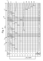
- each DMD mirror may be set to be 'on' during particular DMD update cycles 1, the sequence of 'on' periods required to achieve the perception of each luminance level being shown in Figure 1 as shaded blocks 5.
- the eye of a viewer is able to perceive the pixel at a particular required luminance according to the proportion of a 20ms 'frame period' or 'image refresh period' 10 during which the mirror is 'on'.
- the mirror For a pixel luminance of less than level '5', the mirror will be set to 'on' for respective portions 15, 20, 25, 30 of one of DMD update cycles '31'-'34', DMD update cycle '35' being reserved for mirror testing.
- the fractional pixel luminance levels 1 to 4 may be combined to give any one of sixteen fractional luminance levels. Each of the sixteen fractional luminance levels may itself be combined with any one of pixel luminance levels 5 to 9 to give an increased number of possible pixel luminance levels.
- the respective mirror For a pixel of the highest available luminance, the respective mirror will be on for update cycles '0'-'30' of the 35 available DMD update cycles and for each of the fractional 'on' periods during update cycles '31'-'34'.
- image data are generated on a frame-by-frame basis such that a required pixel luminance level needs to be known at the beginning of a 20ms image refresh period 10 as the luminance level will determine the pattern of modulation to be applied for the pixel in that particular image frame.
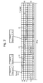
- FIG. 2 the states of respective DMD mirrors for each of three pixels A, B and C are shown for each of DMD update cycles '0' to '34' of a typical 20ms image refresh period 50 and for Pixel C during the immediately following refresh period 55.
- Figure 2 also shows the stored values 60 for a count-down timer store (the timer store itself not being shown in Figure 2 ) associated with each pixel (DMD mirror) at the end of each DMD update cycle whose function will be clear from what follows.
- Pixel A is to be displayed with a luminance level '7' beginning at DMD update cycle '4'.
- luminance level '7' indicates that the respective DMD mirror is to be held in the 'on' state for 7 consecutive DMD update cycles.
- the value '7' is written into a timer store associated with Pixel A before the DMD update cycle in which the pixel is to be illuminated.
- the DMD mirror for Pixel A is switched to or held in the 'on' state for that update cycle.
- the timer value is then decremented and the decremented value is stored in the Pixel A timer store ready for the next update cycle.
- the timer store for Pixel A is decremented to '6' at DMD update cycle '4'.
- the timer value for Pixel A is read from the Pixel A timer store and, being non-zero, causes the DMD mirror for Pixel A to remain 'on' for update cycle '5' and the timer value is decremented to '5'. This process continues until, at update cycle '10', the timer value is decremented to zero. Therefore, at the beginning of update cycle '11', the timer value is zero and the Pixel A DMD mirror is switched to 'off'.
- Fractional values of pixel luminance may be implemented using, in this example, one or more of update cycles '31' to '34' to provide a 4-bit representation and implementation of one of 16 fractional luminance levels (including 'off') under this scheme: a luminance level of 1 ⁇ 2 is achieved by switching the DMD mirror to 'on' for half of DMD update cycle '31'; a luminance level of 1 ⁇ 4 is achieved by switching the DMD mirror to 'on' for one quarter of DMD update cycle '32'; a luminance level of 1/8 is achieved by switching the DMD mirror to 'on' for one eighth of DMD update cycle '33'; and A luminance level of 1/16 is achieved by switching the DMD mirror to 'on' for one sixteenth of DMD update cycle '34'.
- fractional illumination periods provide for the 15 possible fractional levels of pixel illumination.
- the fractional illumination periods may of course be inserted at any position within an image refresh period according to the order chosen for driving the DMD device, retained either as a block of four, or distributed individually throughout the available DMD update cycles 0 to 34 of a refresh period, in this example of a 35 update cycle scheme.
- Pixel B needs to be plotted with a luminance level of '121 ⁇ 2' beginning at DMD update cycle '9'.
- the integer value of luminance, in this case '12' is stored in the Pixel B timer store (not shown in Figure 2 ) and the required fractional value is stored elsewhere to be recalled at one or more of update cycles '31' to '34', in this example at update cycle'31'.
- the value in the Pixel B timer store is non-zero and so the Pixel B DMD mirror is switched to or is held in the 'on' state and the timer value is decremented to '11' and stored.
- the process repeats as for the Pixel A example, until in this case at update cycle '20', the timer value is decremented to zero so that at the beginning of update cycle '21', the timer value is zero and the Pixel B DMD mirror is switched to 'off'.
- the first bit of the stored 4-bit fractional illumination value for Pixel B is recalled and, given that the first bit of the 4-bit value is set in this example to indicate that a 1 ⁇ 2 level illumination is required, triggers the illumination of Pixel B for one half of DMD update cycle '31'.
- Pixel C not only requires a different fractional luminance value (15/16), one involving the use of the fractional illumination levels available in all four of DMD update cycles '31'-'34', i.e. 4-bit fractional luminance value '1111', but also the illumination of the Pixel C DMD mirror for a period that spans two refresh periods, beginning at DMD update cycle '19' of the first refresh period 50 and ending at update cycle '2' of the immediately following refresh period 55.
- the process operates as above for Pixel B, with the objective of inserting the fractional illuminations as soon as possible, in this example at the end of the first refresh period.
- the overlap into the next notional refresh period causes no operational difference in the process of decrementing the timer for Pixel C and switching the Pixel C DMD mirror.
- This is a particular advantage of controlling the DMD under the present invention, in that the concept of an image refresh period becomes largely redundant as all image updates take place beginning at the next available DMD update cycle following generation of the image update and for each of the pixels concerned, ends a number of update cycles later determined only by the required pixel luminance.
- the illumination levels used in the example of Figure 2 are defined in terms of the number of DMD update cycles or fractions of an update cycle during which as pixel is to be illuminated to achieve a required luminance level
- a luminance level in the range may be readily converted into a luminance level as used in Figure 2 by considering each of the DMD cycles in which the pixel is fully illuminated as contributing a luminance weighting of '8' in the 0-255 luminance level scheme.
- the fractional luminance levels in the scheme used in Figure 2 would then contribute the following weightings:
- a conversion process may therefore readily be implemented to convert a luminance level in the range 0-255 to a 9-bit binary number as may be used to control DMD mirror switching according to the scheme described above with reference to Figure 2 and in more detail below.
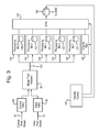
- FIG. 3 a high level functional block diagram is provided showing how the processing of pixel luminance values may be organised from receipt of generated image data, comprising luminance data for one or both of a Cursive Pixel Stream 70 and a Video Pixel Stream 75, to output of data 80 for controlling a DMD (not shown in Figure 3 ). It is assumed for the purposes of this example embodiment that the input luminance values for each pixel are represented as a 9-bit binary number according to a predetermined scheme for driving the DMD.
- a processing block 95 is arranged to merge the input image data streams to form a single data stream 100, optionally including flags generated to identify whether the data defining luminance of a pixel relates to a cursively drawn feature in the image or to a pixel in a video data stream.
- flags generated to identify whether the data defining luminance of a pixel relates to a cursively drawn feature in the image or to a pixel in a video data stream. The inclusion of such flags enables priority to be given in later processing steps to data defining pixels that are part of a cursively drawn symbol over data defining video pixels when determining how to update the image during the immediately following DMD update cycle or cycles.
- the pixel luminance data in the combined data stream 100 are stored in a memory device associated with each of an arrangement of processing modules 105 to 125, arranged in this embodiment to split the processing of image data for DMD update cycles 0 to 30 from that for DMD update cycles 31 to 34.
- the first Processing module 105 is arranged to process bits 5 to 9 of each 9-bit pixel luminance value and the processing modules 110 to 125 are each arranged to process one of bits 1 to 4 of the pixel luminance value.
- the Processing module 105 is arranged to store bits 5-9 of the received pixel luminance data in an associated memory device 108.
- the memory device 108 is arranged to store bits 5 to 9 for each of the 1310720 pixels in the image.
- Bits 5 to 9 represent the number of DMD update cycles during update cycles 0 to 30 of an image refresh period during which the respective DMD mirror is required to be 'on' for the entire update cycle for a given pixel.
- Each of the Processing modules 110 to 125 is provided with access to a respective memory device for the storage of bits 4, 3, 2, and 1 of the 1310720 pixels, in this example of a 1280x1024 pixel image.
- Data bits 4, 3, 2, 1 define whether a DMD mirror is to be switched 'on' for a respective portion of DMD update cycles 31, 32, 33 and 34, providing any one of 16 fractional luminance levels, including 'off'.
- the processing capability provided within each of the modules 105 - 125 implements a predetermined scheme for the update of an image using the received data 100.
- the processing module 105 implements elements of the scheme described above with reference to Figure 2 for determining a pixel timer value to be stored - 'plotted' - and decremented for each pixel in the memory 108 at each DMD update cycle, as will be described in more detail below.
- a Multiplexer (MPX) module 130 is provided to read data from the memory devices 108, 112, 117, 122, 127 associated with the processing modules 105 - 125 under timing controls determined by a Transfer Control module 135 and to generate bit-planes of data, according to a predetermined DMD driving scheme, to be transferred to a memory device (DMD Buffer) 140 associated with the DMD.
- DMD Buffer memory device
- Each bit-plane of data defines which of the DMD mirrors (pixels) are to be illuminated during a respective DMD update cycle.
- the MPX module 130 would be triggered by the Transfer Control module 135 to read data from the memory device 108 associated with the Processing bits 5 to 9 module 105 to drive the DMD; for DMD update cycle 31, the MPX module 130 would be triggered to read data from the memory device 112 associated with the Processing bit 4 module 110, etc.
- the writing of pixel data into the memory devices 108, 112, 117, 122, 127 is inhibited by the Transfer Control module 135 during periods of transfer of bit-plane data from those memory devices to the DMD Buffer 140. During this time the pixels waiting to be plotted may be stored in their respective FIFOs 85, 90.
- the Transfer Control module 135 provides the update timing of the system throughout a 20ms (16.6ms) image refresh period. It times the gap between each DMD update; it counts the update cycles to determine which of the memory devices 108, 112, 117, 122, 127 should be selected for transfer of data to the DMD. It also provides the addressing to transfer every pixel from the memory devices 108, 112, 117, 122, 127 to the DMD Buffer 140 and thus to the DMD.
- DMD Integrity Testing 145 may be triggered to take place during DMD update cycle 35, for example, or it may be triggered to take place during any DMD update cycle within the time interval defined by the image refresh period.
- Processing modules 105, 110, 115, 120, 125 and of the MPX module 130 dedicated to processing bits 5-9 and bits 1, 2, 3 and 4 of a received pixel luminance value will now be described in more detail with reference to Figure 3 and additionally with reference to Figure 4 .
- Those features that are common to both Figure 3 and Figure 4 are labelled using the same reference numerals.
- FIG. 4 a functional block diagram is provided showing the functional features required to process a pixel luminance value and to control the respective DMD mirror over DMD update cycles 0 to 34 to achieve a perception of the pixel luminance represented by the value in those bits.
- Figure 4 shows how functions of the Processing modules 105, 110, 115, 120, 125 and of the MPX module 130 interoperate to generate and output data for each pixel to the DMD Buffer 140 and so determine the state of a respective DMD mirror during each of DMD update cycles 0 to 34.
- the Transfer Control module 135 triggers the MPX module 130 to read pixel data from the memory 108 for those pixels of the image to be updated. For bits 1 to 4, the Transfer Control module 135 triggers the MPX module 130 to read pixel data from the memories 112, 117, 122 and 127 respectively for those pixels of the image to be updated.
- the processing modules 105, 110, 115, 120, 125 implement an Add and Saturate function 150, arranged to receive pixel data from the combined data stream 100 for the pixel and to implement a predetermined scheme for combining any 'cursive' (70) or 'video' (75) pixel data defined therein with a luminance value for the most recent DMD update cycle read from the respective memory 108, 112, 117, 122, 127 and so determine what luminance value should be used from the next DMD update cycle to update that pixel in the image.
- the processing modules also implement a Decrement to Zero function 155 arranged to decrement a luminance value read from the respective memory and to output the new value for storage by the MPX module 130 in the same memory location.
- a different form of 'decay' may be applied to the pixel luminance value, for example multiplication of the currently stored value by a fraction, or application of an exponential reduction scheme to the pixel luminance value represented by bits 5 to 9.
- the Add and Saturate function 150 may arrange to add bits 5 to 9 of a new pixel luminance value 100 to the currently stored luminance value read from the memory 108 or, if greater than the currently stored luminance value, it may replace the currently stored luminance value for output to the MPX module 130 and storage in the memory 108. If the sum of the current luminance value and the new pixel luminance value exceeds 31, corresponding to full illumination of the next 31 DMD update cycles that may be controlled by bits 5 to 9 of the pixel luminance value, the value '31' is written into the pixel store in the memory 108.
- the Add and Saturate function 150 may be arranged to give priority to the luminance value for the cursive update over that for the video update when determining the luminance value to be added to or to replace the currently stored pixel luminance in the memory 108, in particular if the cursive luminance value is greater than the video update luminance value for the pixel.
- a pixel luminance level defined by bits 5 to 9 is achieved using the method described above with reference to Figure 2 in which the pixel is illuminated (DMD mirror is switched to 'on') for as long as the pixel luminance value read from the memory 108, remains non-zero.
- the value is also returned for processing by the Add and Saturate function 150 according to the schemes described above, to be combined with newly received image data 100, or to be decremented by the Decrement to Zero function 155 before output to the MPX module 130 and storage in the memory 108 for use in the next DMD update cycle.
- the Transfer Control module 135 is arranged to inhibit all plotting of new pixel data into the memory 108, 112, 117, 122, 127 while the contents of the memory are being read as a bit-plane of data and transferred to the DMD Buffer 140.
- each of the second to fifth processing modules 110-125 dedicated to processing bits 4, 3, 2, and 1 of each pixel luminance value respectively, is generally similar to that described above for bits 5 to 9, except of course that the bit values in positions 1 to 4 each represent only a single DMD update cycle and the Decrement to Zero function 155 operates trivially to permit only a single update cycle to be influenced by the respective bit value for a pixel, unless replaced by the Add and Saturate function 150 based upon newly received data for the pixel.
- the Transfer Control modules 135 triggers the MPX module 130 to read pixel data from the memories 112, 117, 122, 127 respectively when assembling the bit-planes of data for transfer to the DMD Buffer 140 for the fractional luminance levels.
- the Add and Saturate function 150 operates an equivalent scheme to that for bits 5 to 9, but at the level of fractional additions or replacements and the setting or resetting of respective bits 1 to 4 based upon the received image data 100, as would be apparent to a notional skilled person in this field.
- the Transfer Control module 135 is arranged to inhibit plotting of fractional illumination of pixels into the memories 112, 117, 122, 127 while the latest bit-plane of data for any of update cycles 31 to 34 is being assembled and transferred to the DMD Buffer 140.
- a DMD driving scheme based upon 35 DMD update cycles within a 20ms image refresh period may of course be varied according to the switching speed of the DMD device and the speed of the data bus and processing modules associated with it.
- future devices may be able to support the use of 256 DMD update cycles of approximately 78 ⁇ s within each 20ms 'image refresh' period.
- a received pixel luminance value in the range 0-255 may then be used directly as a timer value defining the number of 78 ⁇ s update cycles during which the pixel is to be illuminated, providing for a simplification in the processing functionality described above with reference to Figure 4 as the fractional illumination levels would no longer be required.
- One alternative DMD driving scheme that may be implemented in an example embodiment of the present invention using the best devices currently available makes use of 63 DMD cycles of full pixel illumination and 3 fractional cycles per 20ms image refresh period, rather than the 31 cycles of full illumination and 4 cycles of fractional illumination as described above. Such a scheme may be readily implemented using a corresponding arrangement of the apparatus described above with reference to Figures 3 and 4 as would be apparent to a notional skilled person in this field. Similarly, a DMD driving scheme may be implemented based upon a smaller number of DMD update cycles per image refresh period, for example using 15 cycles of full pixel illumination and 5 cycles of fractional illumination according to another example embodiment of the present invention.
- a different approach may be taken to the method for controlling the period for which a pixel is to remain 'on'.
- an arrangement may be implemented involving the use of a shift register associated with each pixel.
- a shift register may be implemented in memory for each pixel, the shift register having a bit-length equal to the number of DMD update cycles in an image refresh period.
- the shift register may be filled with that given number of 1 s as a contiguous string, the remaining bit positions being set to or remaining at 0.
- the bits in the shift register are shifted along one bit position at the beginning of each update cycle and the emerging value read. Therefore, the position within the shift register at which the one or more 1s are written determines at which DMD update cycle in the future the respective pixel will be switched 'on'.
- the number of 1s written into the shift register starting at that position determines the number of DMD update cycles for which, when the bits are shifted, a 1 emerges from the register and the pixel will be or remain illuminated.
- a parallel loading shift register may be provided for each pixel so that updates to its content may be made at any bit position within the register at any time (other than when the register is being shifted) under the control of processing functionality as described above with reference to Figures 3 and 4 .
- the arrangement of 1 s in the shift register may be updated in response to a result of applying any of the example methods described or mentioned above for determining how an update to an image at a given DMD update cycle will affect the illumination of a pixel.
- LCD liquid crystal display
- a notional cycle of 'full' pixel illumination for an LCD display device may comprise a period during which the pixel is illuminated, followed by a period of equivalent length during which the pixel is not illuminated in order to satisfy the device requirements for so-called 'pixel balancing', all within the equivalent of a DMD update cycle or at least within the time period defined by the image refresh period, as is usual for display devices based upon liquid crystal material.
- the overall determination of a pattern of modulation based upon a count-down timer, shift register or other memory arrangement, as in example embodiments of the present invention described above, may still be applied to the control of LCD and other digital display device types with corresponding modification to the final implementation of 'full' or fractional illumination of a pixel at the display device.
Landscapes
- Engineering & Computer Science (AREA)
- Physics & Mathematics (AREA)
- Computer Hardware Design (AREA)
- General Physics & Mathematics (AREA)
- Theoretical Computer Science (AREA)
- Control Of Indicators Other Than Cathode Ray Tubes (AREA)
Abstract
A method for controlling a digital display device and a digital display system implementing the method are provided in which a required luminance level for a pixel is controlled according to a store provided for each pixel, the contents of which indicate the number of discrete display update periods during an image refresh period for the pixel for which the pixel is to be illuminated to achieve the required luminance level, the content being read at each update period and the content determining whether the pixel is to be illuminated for that update period, the content being updated at each update period for which the pixel is illuminated to indicate that the number of update cycles for which the pixel is to be illuminated is thereby reduced by one and wherein the content of the store may be updated at any update cycle in response to changes in required pixel luminance level indicated by received image data.
Description
- This invention relates to digital displays and in particular, but not exclusively, to a method and apparatus for controlling the display of images in digital display devices, for example digital displays based upon a digital micromirror device (DMD), a liquid crystal display (LCD) device or a liquid crystal on silicon (LCOS) display device. However, the principles of operation of the present invention may be applied advantageously to other types of digital display device.
- A DMD comprises an array of micro-mirrors which can be individually and selectively activated by controlling the angle at which they reflect incident light. An array of micro-mirrors corresponds to an array of pixels in an image to be displayed. In an 'on' state a mirror reflects light for displaying a pixel of an image and in an 'off' state the mirror reflects the light to a light dump. A DMD has an 'update period' which may vary from one type of device to another or may be selected by a system designer dependent on the required performance of the system. The DMD update period is the time period during which the micro-mirrors can be controlled to be switched to or held in either an 'on' state or an 'off' state. By way of example, a typical DMD update period may be between 200µs and 600µs so that each of the mirrors may be controlled to change state every 200µs to 600µs. A display is required to maintain each pixel of an image for a minimum period - an 'image refresh period' to allow proper perception by a human observer. An image refresh period of 16 or 20ms is typical and represents a time period less than the minimum period during which a human eye is able to perceive a change in pixel luminance or colour. Accordingly, the state of each pixel represented in the DMD can be changed many times during a refresh period and the eye will integrate the discrete periods of illumination to result in a single perceived luminance level over that image refresh period. For example, a DMD update period of 572µs allows the state of a mirror to be changed 35 times and perceived illumination levels to be achieved using predetermined combinations of those 35 mirror state changes during a refresh period of 20ms.
- Conventional methods for controlling the state of the micro-mirrors in a DMD device to render an image operate on a frame-by-frame basis, the image data required to define the pixels for the image in each frame being determined in time for the beginning of a 16 to 20ms 'frame period' or 'image refresh period' typically. The pixel luminance and colour to be displayed in a given frame needs to be uploaded to a DMD 'driver' in time for the beginning of a respective frame period and a predetermined pattern of mirror modulation is applied by the DMD driver in respect of each pixel during that frame period to ensure that pixels of the required luminance and colour (if the image is a colour image) may be perceived for that image frame by a viewer. However, one difficulty with this approach is that updates to an image to be displayed, for example the appearance of a new element of a cursively drawn symbol in the image, cannot be introduced into the image being displayed until the beginning of the next 20ms frame period. In some applications such a delay is unacceptable.
- Various attempts have been made to introduce image updates during a frame period by combining new portions of an image as they are generated, for example elements of a cursively drawn symbol, to an image being displayed, beginning at the next available DMD update cycle, rather than wait until the next frame period to begin plotting the new symbol. One example of such an approach is described in an international patent application by the present Applicant, published on
26 September 2013 as WO 2013/140143 , in which a dual image buffer arrangement is provided to enable new image portions to be 'plotted' into an image at a given DMD update cycle during one frame period and 'unplotted' at a corresponding DMD update cycle of the next frame period, with a respective pattern of DMD pixel modulation being applied to the affected pixels between plotting and unplotting to achieve the required overall pixel luminance. - In a first aspect, the present invention resides in a method for controlling a digital display device to display an image, by which method a perceived luminance level for a pixel in an image to be displayed by the digital display device is achieved by controlling a respective region of the display device to illuminate the pixel for a predetermined portion of an image refresh period for the pixel, the portion being indicated by the content of a store provided in respect of the pixel, the content representing a number of discrete display device update periods of predetermined length within the image refresh period for the pixel during which the pixel is to be illuminated such that the pixel is illuminated for the portion of the image refresh period, wherein the content of the store at each update period determines whether the respective pixel is to be illuminated or not illuminated for that update period and the content of the store is updated at each update period for which the pixel is illuminated to indicate that the number of update periods for which the pixel is to be illuminated is reduced by one and wherein the content of the store may be updated at any update period to implement an update to the luminance level required for the pixel in response to received image data.
- In one example embodiment, a pixel may be illuminated for a portion of an update cycle and the content of the store determines which of one or more predetermined display update cycles during the image refresh period for the pixel are designated for the purpose of illumination of the pixel for a respective portion of the update cycle, so enabling the perception of one or more fractional levels of pixel luminance.
- In a particular example embodiment, four predetermined update cycles during an image refresh period for a pixel are reserved for the illumination of the pixel for a different respective portion of the update cycle, so providing for up to fifteen fractional levels of pixel luminance.
- In a further example embodiment, the method further comprises the steps:
- receiving image data defining luminance levels for pixels of an image to be displayed by the display device;
- storing in a store provided for each pixel an indication of the number of update periods for which the pixel is to be fully illuminated;
- retrieving the stored content for each pixel to be updated in the image during a given update period; and
- in the event that the retrieved content indicates that the pixel is to be illuminated for the given update period, controlling the display device to illuminate the pixel during the update period and updating the content of the store to indicate that the number of update periods for which the pixel is to be illuminated is reduced by one.
- In another example embodiment, the store comprises a count-down timer value store for each pixel defining the number of update periods for which the pixel is to be illuminated and wherein updating the store at each update period comprises decrementing the stored time value for the pixel such that when the stored value reaches zero, the pixel will no longer be illuminated.
- In an alternative implementation, the store comprises a shift register for each pixel of bit-length equal to the number of update periods in the image refresh period for the pixel, wherein the number of update periods for which the pixel is to be illuminated is indicated by the number of bits set in the shift register, and wherein updating the store at each update period comprises shifting the bits in the shift register by one position such that when a bit is read from the shift register, the respective pixel will be illuminated if the bit is set, or otherwise the pixel will no longer be illuminated.
- In a further variant, any bit of the shift register may be updated at any update cycle in response to received image data causing an update to the required luminance level for the respective pixel.
- In a second aspect, the present invention resides in a digital display system, comprising:
- a digital display device for displaying an image; and
- a display controller arranged to control the digital display device to display pixels in an image at a required level of luminance by controlling a respective region of the display device to illuminate a pixel for a respective portion of an image refresh period for the pixel,
- wherein the display controller comprises:
- an input for receiving image data defining luminance levels for one or more pixels in an image to be displayed or updated;
- a processor arranged with access to a store provided for each pixel:
- to receive image data from the input defining a required luminance level for a pixel;
- to store in the store provided for the pixel an indication of a number of discrete display device update periods of predetermined length within the image refresh period for the pixel during which the pixel is to be illuminated such that the pixel is illuminated for a portion of the image refresh period corresponding to the required luminance level for the pixel;
- to read the content of the store for each pixel at each update period and to generate an output to indicate which pixels are to be illuminated for the update period and which are not to be illuminated, in dependence upon the content of the respective pixel stores;
- to update the content of the store for each pixel at each update period for which the content indicates that the pixel is to be illuminated to indicate that the number of update periods for which the pixel is to be illuminated is reduced by one; and
- to update the content of the store at any update period to implement an update to the luminance level required for the pixel in response to received image data, and
- means for receiving output from the processor and to cause the display device to illuminate pixels during a given display update period according to the output indications.
- In an example embodiment of the system, a pixel may be illuminated for a portion of an update cycle and wherein the content of the store determines which of one or more predetermined display update cycles during the image refresh period for the pixel are designated for the purpose of illumination of the pixel for a respective portion of the update cycle, so enabling the perception of one or more fractional levels of pixel luminance.
- In a particular example embodiment, four predetermined update cycles during an image refresh period for a pixel are reserved for the illumination of the pixel for a different respective portion of the update cycle, so providing for up to fifteen fractional levels of pixel luminance.
- In another example embodiment of the system, the store comprises a count-down timer value store for each pixel defining the number of update periods for which the pixel is to be illuminated and wherein updating the store at each update period comprises decrementing the stored time value for the pixel such that when the stored value reaches zero, the pixel will no longer be illuminated.
- In an alternative implementation, the store comprises a shift register for each pixel of bit-length equal to the number of update periods in the image refresh period for the pixel, wherein the number of update periods for which the pixel is to be illuminated is indicated by the number of bits set in the shift register, and wherein updating the store at each update period comprises shifting the bits in the shift register by one position such that when a bit is read from the shift register, the respective pixel will be illuminated if the bit is set, or otherwise the pixel will no longer be illuminated.
- In a further variant, the processor is arranged with access to update any bit of the shift register at any update cycle in response to received image data causing an update to the required luminance level for the respective pixel.
- In a third aspect, the present invention resides in a digital display device incorporating or associated with a controller arranged to implement the method according to any embodiment of the first aspect of the present invention.
- In a fourth aspect, the present invention resides in a digital display device controllable according to the method defined according to any embodiment of the first aspect of the present invention.
- The present invention aims to provide a much simplified approach to the modulation of DMD mirrors and to the management of an image buffer in an improved DMD controller to enable updates to an image to be introduced as they are required, beginning as soon as the next DMD update cycle. The present invention may be applied similarly to other types of digital display device, as would be apparent to a notional skilled person in the field.
- Example embodiments of the present invention will now be described in more detail with reference to the accompanying drawings, of which:
-
Figure 1 shows a known DMD modulation scheme for achieving one or ten pixel luminance levels; -
Figure 2 shows a scheme for controlling the luminance of pixels in a DMD display according to one example embodiment of the present invention; and -
Figures 3 and4 show functional block diagrams of the processing and data storage features in one example implementation of the present invention. - Referring initially to
Figure 1 , an example of a DMD mirror modulation scheme is shown for generating any of ten different pixel luminance levels '1' to '10' as may be used singly or in combination to illuminate pixels in a frame of video image data or a still image using a DMD device. Under such a scheme, each DMD mirror may be set to be 'on' during particularDMD update cycles 1, the sequence of 'on' periods required to achieve the perception of each luminance level being shown inFigure 1 asshaded blocks 5. The eye of a viewer is able to perceive the pixel at a particular required luminance according to the proportion of a 20ms 'frame period' or 'image refresh period' 10 during which the mirror is 'on'. For a pixel luminance of less than level '5', the mirror will be set to 'on' forrespective portions pixel luminance levels 1 to 4 may be combined to give any one of sixteen fractional luminance levels. Each of the sixteen fractional luminance levels may itself be combined with any one ofpixel luminance levels 5 to 9 to give an increased number of possible pixel luminance levels. For a pixel of the highest available luminance, the respective mirror will be on for update cycles '0'-'30' of the 35 available DMD update cycles and for each of the fractional 'on' periods during update cycles '31'-'34'. - Under a known method for generating an image, image data are generated on a frame-by-frame basis such that a required pixel luminance level needs to be known at the beginning of a 20ms
image refresh period 10 as the luminance level will determine the pattern of modulation to be applied for the pixel in that particular image frame. - In the present invention, a different approach has been devised for modulating DMD mirrors that is constrained neither by the fixed 20ms frame periods of certain prior art systems, nor by the predetermined mirror modulation scheme shown in
Figure 1 . The operating principles of this scheme will now be described by way of example with reference toFigure 2 . - Referring to
Figure 2 , the states of respective DMD mirrors for each of three pixels A, B and C are shown for each of DMD update cycles '0' to '34' of a typical 20msimage refresh period 50 and for Pixel C during the immediately followingrefresh period 55.Figure 2 also shows the storedvalues 60 for a count-down timer store (the timer store itself not being shown inFigure 2 ) associated with each pixel (DMD mirror) at the end of each DMD update cycle whose function will be clear from what follows. - As can be seen in
Figure 2 , Pixel A is to be displayed with a luminance level '7' beginning at DMD update cycle '4'. Under this scheme, luminance level '7' indicates that the respective DMD mirror is to be held in the 'on' state for 7 consecutive DMD update cycles. The value '7' is written into a timer store associated with Pixel A before the DMD update cycle in which the pixel is to be illuminated. At the beginning of each DMD update cycle, if the value stored in the Pixel A timer store is non-zero, the DMD mirror for Pixel A is switched to or held in the 'on' state for that update cycle. The timer value is then decremented and the decremented value is stored in the Pixel A timer store ready for the next update cycle. As can be seen inFigure 2 , the timer store for Pixel A is decremented to '6' at DMD update cycle '4'. At the beginning of update cycle '5', the timer value for Pixel A is read from the Pixel A timer store and, being non-zero, causes the DMD mirror for Pixel A to remain 'on' for update cycle '5' and the timer value is decremented to '5'. This process continues until, at update cycle '10', the timer value is decremented to zero. Therefore, at the beginning of update cycle '11', the timer value is zero and the Pixel A DMD mirror is switched to 'off'. - Fractional values of pixel luminance may be implemented using, in this example, one or more of update cycles '31' to '34' to provide a 4-bit representation and implementation of one of 16 fractional luminance levels (including 'off') under this scheme: a luminance level of ½ is achieved by switching the DMD mirror to 'on' for half of DMD update cycle '31'; a luminance level of ¼ is achieved by switching the DMD mirror to 'on' for one quarter of DMD update cycle '32'; a luminance level of 1/8 is achieved by switching the DMD mirror to 'on' for one eighth of DMD update cycle '33'; and A luminance level of 1/16 is achieved by switching the DMD mirror to 'on' for one sixteenth of DMD update cycle '34'. Different combinations of these four fractional illumination periods provide for the 15 possible fractional levels of pixel illumination. The fractional illumination periods may of course be inserted at any position within an image refresh period according to the order chosen for driving the DMD device, retained either as a block of four, or distributed individually throughout the available DMD update cycles 0 to 34 of a refresh period, in this example of a 35 update cycle scheme.
- In the example shown in
Figure 2 , it can be seen that Pixel B needs to be plotted with a luminance level of '12½' beginning at DMD update cycle '9'. The integer value of luminance, in this case '12', is stored in the Pixel B timer store (not shown inFigure 2 ) and the required fractional value is stored elsewhere to be recalled at one or more of update cycles '31' to '34', in this example at update cycle'31'. At DMD update cycle '9', the value in the Pixel B timer store is non-zero and so the Pixel B DMD mirror is switched to or is held in the 'on' state and the timer value is decremented to '11' and stored. The process repeats as for the Pixel A example, until in this case at update cycle '20', the timer value is decremented to zero so that at the beginning of update cycle '21', the timer value is zero and the Pixel B DMD mirror is switched to 'off'. At DMD update cycle '31', the first bit of the stored 4-bit fractional illumination value for Pixel B is recalled and, given that the first bit of the 4-bit value is set in this example to indicate that a ½ level illumination is required, triggers the illumination of Pixel B for one half of DMD update cycle '31'. - In the example of
Figure 2 , it can be seen that Pixel C not only requires a different fractional luminance value (15/16), one involving the use of the fractional illumination levels available in all four of DMD update cycles '31'-'34', i.e. 4-bit fractional luminance value '1111', but also the illumination of the Pixel C DMD mirror for a period that spans two refresh periods, beginning at DMD update cycle '19' of thefirst refresh period 50 and ending at update cycle '2' of the immediately followingrefresh period 55. - The process operates as above for Pixel B, with the objective of inserting the fractional illuminations as soon as possible, in this example at the end of the first refresh period. The overlap into the next notional refresh period causes no operational difference in the process of decrementing the timer for Pixel C and switching the Pixel C DMD mirror. This is a particular advantage of controlling the DMD under the present invention, in that the concept of an image refresh period becomes largely redundant as all image updates take place beginning at the next available DMD update cycle following generation of the image update and for each of the pixels concerned, ends a number of update cycles later determined only by the required pixel luminance.
- Whereas the illumination levels used in the example of
Figure 2 are defined in terms of the number of DMD update cycles or fractions of an update cycle during which as pixel is to be illuminated to achieve a required luminance level, it is conventional, for example when using an 8-bit video data signal, to define luminance as one oflevels 0 to 255. A luminance level in the range may be readily converted into a luminance level as used inFigure 2 by considering each of the DMD cycles in which the pixel is fully illuminated as contributing a luminance weighting of '8' in the 0-255 luminance level scheme. The fractional luminance levels in the scheme used inFigure 2 would then contribute the following weightings: - ½ cycle illumination as a weighting of 4;
- ¼ cycle illumination as a weighting of 2;
- 1/8 cycle illumination as a weighting of 1; and
- 1/16 cycle illumination as a weighting of ½.
- This provides for any one of
illumination levels 0 to 255½. A conversion process may therefore readily be implemented to convert a luminance level in the range 0-255 to a 9-bit binary number as may be used to control DMD mirror switching according to the scheme described above with reference toFigure 2 and in more detail below. - One example functional implementation of the present invention will now be described with reference to
Figures 3 and4 , each providing a functional representation of the operational elements of a display system based upon a DMD and implementing the principles described by way of example above. - Referring firstly to
Figure 3 , a high level functional block diagram is provided showing how the processing of pixel luminance values may be organised from receipt of generated image data, comprising luminance data for one or both of aCursive Pixel Stream 70 and aVideo Pixel Stream 75, to output of data 80 for controlling a DMD (not shown inFigure 3 ). It is assumed for the purposes of this example embodiment that the input luminance values for each pixel are represented as a 9-bit binary number according to a predetermined scheme for driving the DMD. One reason for using a 9-bit representation (0-511) rather than an 8-bit representation of video data is to help to maintain a desirable number of distinct pixel luminance levels in the event that a 'gamma correction' is applied to one or more regions of the image to be displayed. If an 8-bit representation were to be used there is an increased risk that distinct luminance levels in the input video data would, after gamma correction at the 8-bit level, no longer be distinct. It is also known to use more than 9 bits to encode video data for this reason, but for the purposes of this example embodiment of the present invention, a 9-bit representation will be assumed. - In conjunction with
respective buffering FIFOs processing block 95 is arranged to merge the input image data streams to form asingle data stream 100, optionally including flags generated to identify whether the data defining luminance of a pixel relates to a cursively drawn feature in the image or to a pixel in a video data stream. The inclusion of such flags enables priority to be given in later processing steps to data defining pixels that are part of a cursively drawn symbol over data defining video pixels when determining how to update the image during the immediately following DMD update cycle or cycles. - The pixel luminance data in the combined
data stream 100 are stored in a memory device associated with each of an arrangement ofprocessing modules 105 to 125, arranged in this embodiment to split the processing of image data for DMD update cycles 0 to 30 from that for DMD update cycles 31 to 34. Thefirst Processing module 105 is arranged to processbits 5 to 9 of each 9-bit pixel luminance value and theprocessing modules 110 to 125 are each arranged to process one ofbits 1 to 4 of the pixel luminance value. - The
Processing module 105 is arranged to store bits 5-9 of the received pixel luminance data in an associatedmemory device 108. In a typical image of 1280x1024 pixels, thememory device 108 is arranged to storebits 5 to 9 for each of the 1310720 pixels in the image.Bits 5 to 9 represent the number of DMD update cycles duringupdate cycles 0 to 30 of an image refresh period during which the respective DMD mirror is required to be 'on' for the entire update cycle for a given pixel. Each of theProcessing modules 110 to 125 is provided with access to a respective memory device for the storage ofbits Data bits - The processing capability provided within each of the modules 105 - 125 implements a predetermined scheme for the update of an image using the received
data 100. Theprocessing module 105, in particular, implements elements of the scheme described above with reference toFigure 2 for determining a pixel timer value to be stored - 'plotted' - and decremented for each pixel in thememory 108 at each DMD update cycle, as will be described in more detail below. - A Multiplexer (MPX)
module 130 is provided to read data from thememory devices Transfer Control module 135 and to generate bit-planes of data, according to a predetermined DMD driving scheme, to be transferred to a memory device (DMD Buffer) 140 associated with the DMD. Each bit-plane of data defines which of the DMD mirrors (pixels) are to be illuminated during a respective DMD update cycle. Thus, for DMD update cycles 0 to 30, theMPX module 130 would be triggered by theTransfer Control module 135 to read data from thememory device 108 associated with theProcessing bits 5 to 9module 105 to drive the DMD; forDMD update cycle 31, theMPX module 130 would be triggered to read data from thememory device 112 associated with theProcessing bit 4module 110, etc. The writing of pixel data into thememory devices Transfer Control module 135 during periods of transfer of bit-plane data from those memory devices to theDMD Buffer 140. During this time the pixels waiting to be plotted may be stored in theirrespective FIFOs - Once the pixel data are plotted (loaded) into the
memory devices Transfer Control module 135 on respective update cycles of the DMD. TheTransfer Control module 135 provides the update timing of the system throughout a 20ms (16.6ms) image refresh period. It times the gap between each DMD update; it counts the update cycles to determine which of thememory devices memory devices DMD Buffer 140 and thus to the DMD.DMD Integrity Testing 145 may be triggered to take place duringDMD update cycle 35, for example, or it may be triggered to take place during any DMD update cycle within the time interval defined by the image refresh period. - The functionality of the
Processing modules MPX module 130 dedicated to processing bits 5-9 andbits Figure 3 and additionally with reference toFigure 4 . Those features that are common to bothFigure 3 andFigure 4 are labelled using the same reference numerals. - Referring additionally to
Figure 4 , a functional block diagram is provided showing the functional features required to process a pixel luminance value and to control the respective DMD mirror over DMD update cycles 0 to 34 to achieve a perception of the pixel luminance represented by the value in those bits. In particular,Figure 4 shows how functions of theProcessing modules MPX module 130 interoperate to generate and output data for each pixel to theDMD Buffer 140 and so determine the state of a respective DMD mirror during each of DMD update cycles 0 to 34. - In respect of
bits 5 to 9 of pixel luminance values, theTransfer Control module 135 triggers theMPX module 130 to read pixel data from thememory 108 for those pixels of the image to be updated. Forbits 1 to 4, theTransfer Control module 135 triggers theMPX module 130 to read pixel data from thememories processing modules Saturate function 150, arranged to receive pixel data from the combineddata stream 100 for the pixel and to implement a predetermined scheme for combining any 'cursive' (70) or 'video' (75) pixel data defined therein with a luminance value for the most recent DMD update cycle read from therespective memory MPX module 130 in the same memory location. However, in respect of the luminance contribution bybits 5 to 9, rather than decrementing the luminance value through a simple subtraction by 1 or by another integer, a different form of 'decay' may be applied to the pixel luminance value, for example multiplication of the currently stored value by a fraction, or application of an exponential reduction scheme to the pixel luminance value represented bybits 5 to 9. - Under one example scheme for combining received
image data 100 with currently stored pixel luminance levels, the Add andSaturate function 150 may arrange to addbits 5 to 9 of a newpixel luminance value 100 to the currently stored luminance value read from thememory 108 or, if greater than the currently stored luminance value, it may replace the currently stored luminance value for output to theMPX module 130 and storage in thememory 108. If the sum of the current luminance value and the new pixel luminance value exceeds 31, corresponding to full illumination of the next 31 DMD update cycles that may be controlled bybits 5 to 9 of the pixel luminance value, the value '31' is written into the pixel store in thememory 108. If the newly received pixel luminance data includes luminance values for both a cursive update and a video update to the image, then the Add andSaturate function 150 may be arranged to give priority to the luminance value for the cursive update over that for the video update when determining the luminance value to be added to or to replace the currently stored pixel luminance in thememory 108, in particular if the cursive luminance value is greater than the video update luminance value for the pixel. - A pixel luminance level defined by
bits 5 to 9 is achieved using the method described above with reference toFigure 2 in which the pixel is illuminated (DMD mirror is switched to 'on') for as long as the pixel luminance value read from thememory 108, remains non-zero. As can be seen inFigure 4 , each time a pixel luminance value is read from thememory 108 for transfer by theMPX module 130 in a respective bit-plane to theDMD Buffer 140, the value is also returned for processing by the Add and Saturate function 150 according to the schemes described above, to be combined with newly receivedimage data 100, or to be decremented by the Decrement to Zero function 155 before output to theMPX module 130 and storage in thememory 108 for use in the next DMD update cycle. TheTransfer Control module 135 is arranged to inhibit all plotting of new pixel data into thememory DMD Buffer 140. - The functionality of each of the second to fifth processing modules 110-125, dedicated to
processing bits bits 5 to 9, except of course that the bit values inpositions 1 to 4 each represent only a single DMD update cycle and the Decrement to Zero function 155 operates trivially to permit only a single update cycle to be influenced by the respective bit value for a pixel, unless replaced by the Add and Saturate function 150 based upon newly received data for the pixel. For each of DMD update cycles 31-34, theTransfer Control modules 135 triggers theMPX module 130 to read pixel data from thememories DMD Buffer 140 for the fractional luminance levels. Forbits 1 to 4, the Add andSaturate function 150 operates an equivalent scheme to that forbits 5 to 9, but at the level of fractional additions or replacements and the setting or resetting ofrespective bits 1 to 4 based upon the receivedimage data 100, as would be apparent to a notional skilled person in this field. TheTransfer Control module 135 is arranged to inhibit plotting of fractional illumination of pixels into thememories DMD Buffer 140. - A DMD driving scheme based upon 35 DMD update cycles within a 20ms image refresh period, as described by way of example above, may of course be varied according to the switching speed of the DMD device and the speed of the data bus and processing modules associated with it. For example, future devices may be able to support the use of 256 DMD update cycles of approximately 78µs within each 20ms 'image refresh' period. A received pixel luminance value in the range 0-255 may then be used directly as a timer value defining the number of 78µs update cycles during which the pixel is to be illuminated, providing for a simplification in the processing functionality described above with reference to
Figure 4 as the fractional illumination levels would no longer be required. - One alternative DMD driving scheme that may be implemented in an example embodiment of the present invention using the best devices currently available makes use of 63 DMD cycles of full pixel illumination and 3 fractional cycles per 20ms image refresh period, rather than the 31 cycles of full illumination and 4 cycles of fractional illumination as described above. Such a scheme may be readily implemented using a corresponding arrangement of the apparatus described above with reference to
Figures 3 and4 as would be apparent to a notional skilled person in this field. Similarly, a DMD driving scheme may be implemented based upon a smaller number of DMD update cycles per image refresh period, for example using 15 cycles of full pixel illumination and 5 cycles of fractional illumination according to another example embodiment of the present invention. - In another example embodiment of the present invention, a different approach may be taken to the method for controlling the period for which a pixel is to remain 'on'. As an alternative to using a count-down timer store for each pixel, an arrangement may be implemented involving the use of a shift register associated with each pixel. Although the use of a shift register requires more memory than a count-down timer store, constraints associated with memory capacity would be expected to reduce in future display devices. In this embodiment, a shift register may be implemented in memory for each pixel, the shift register having a bit-length equal to the number of DMD update cycles in an image refresh period. If a pixel is to be illuminated for a given number of DMD update cycles, the shift register may be filled with that given number of 1 s as a contiguous string, the remaining bit positions being set to or remaining at 0. The bits in the shift register are shifted along one bit position at the beginning of each update cycle and the emerging value read. Therefore, the position within the shift register at which the one or more 1s are written determines at which DMD update cycle in the future the respective pixel will be switched 'on'. The number of 1s written into the shift register starting at that position determines the number of DMD update cycles for which, when the bits are shifted, a 1 emerges from the register and the pixel will be or remain illuminated.
- To enable the shift register to be updated in time for the update to take effect at any selected DMD update cycle in the future, a parallel loading shift register may be provided for each pixel so that updates to its content may be made at any bit position within the register at any time (other than when the register is being shifted) under the control of processing functionality as described above with reference to
Figures 3 and4 . In particular, the arrangement of 1 s in the shift register may be updated in response to a result of applying any of the example methods described or mentioned above for determining how an update to an image at a given DMD update cycle will affect the illumination of a pixel. - Whereas example embodiments of the present invention have been described above in the context of a DMD device, the same techniques may be applied to the control of other types of digital display device, for example liquid crystal display (LCD) devices, with appropriate modifications of the display driver functionality and electronics to ensure that an appropriate pattern of modulation may be applied to the display device during an image refresh period to achieve the required distribution of pixel illumination. In particular, a notional cycle of 'full' pixel illumination for an LCD display device may comprise a period during which the pixel is illuminated, followed by a period of equivalent length during which the pixel is not illuminated in order to satisfy the device requirements for so-called 'pixel balancing', all within the equivalent of a DMD update cycle or at least within the time period defined by the image refresh period, as is usual for display devices based upon liquid crystal material. However, the overall determination of a pattern of modulation based upon a count-down timer, shift register or other memory arrangement, as in example embodiments of the present invention described above, may still be applied to the control of LCD and other digital display device types with corresponding modification to the final implementation of 'full' or fractional illumination of a pixel at the display device.
Claims (15)
- A method for controlling a digital display device to display an image, by which method a perceived luminance level for a pixel in an image to be displayed by the digital display device is achieved by controlling a respective region of the display device to illuminate the pixel for a predetermined portion of an image refresh period for the pixel, said portion being indicated by the content of a store provided in respect of the pixel, the content representing a number of discrete display device update periods of predetermined length within the image refresh period for the pixel during which the pixel is to be illuminated such that the pixel is illuminated for said portion of the image refresh period, wherein the content of the store at each update period determines whether the respective pixel is to be illuminated or not illuminated for that update period and the content of the store is updated at each update period for which the pixel is illuminated to indicate that the number of update periods for which the pixel is to be illuminated is reduced by one and wherein the content of the store may be updated at any update period to implement an update to the luminance level required for the pixel in response to received image data.
- The method according to claim 1, wherein a pixel may be illuminated for a portion of an update cycle and wherein the content of the store determines which of one or more predetermined display update cycles during the image refresh period for the pixel are designated for the purpose of illumination of the pixel for a respective portion of the update cycle, so enabling the perception of one or more fractional levels of pixel luminance.
- The method according to claim 2, wherein four predetermined update cycles during an image refresh period for a pixel are reserved for the illumination of the pixel for a different respective portion of the update cycle, so providing for up to fifteen fractional levels of pixel luminance.
- The method according to any one of the preceding claims, comprising the steps:receiving image data defining luminance levels for pixels of an image to be displayed by the display device;storing in a store provided for each pixel an indication of the number of update periods for which the pixel is to be fully illuminated;retrieving the stored content for each pixel to be updated in the image during a given update period; andin the event that the retrieved content indicates that the pixel is to be illuminated for the given update period, controlling the display device to illuminate the pixel during the update period and updating the content of the store to indicate that the number of update periods for which the pixel is to be illuminated is reduced by one.
- The method according to any one of the preceding claims, wherein the store comprises a count-down timer value store for each pixel defining the number of update periods for which the pixel is to be illuminated and wherein updating the store at each update period comprises decrementing the stored time value for the pixel such that when the stored value reaches zero, the pixel will no longer be illuminated.
- The method according to any one of claims 1 to 5, wherein the store comprises a shift register for each pixel of bit-length equal to the number of update periods in the image refresh period for the pixel, wherein the number of update periods for which the pixel is to be illuminated is indicated by the number of bits set in the shift register, and wherein updating the store at each update period comprises shifting the bits in the shift register by one position such that when a bit is read from the shift register, the respective pixel will be illuminated if the bit is set, or otherwise the pixel will no longer be illuminated.
- The method according to claim 6, wherein any bit of the shift register may be updated at any update cycle in response to received image data causing an update to the required luminance level for the respective pixel.
- A digital display system, comprising:a digital display device for displaying an image; anda display controller arranged to control the digital display device to display pixels in an image at a required level of luminance by controlling a respective region of the display device to illuminate a pixel for a respective portion of an image refresh period for the pixel,wherein the display controller comprises:an input for receiving image data defining luminance levels for one or more pixels in an image to be displayed or updated;a processor arranged with access to a store provided for each pixel:to receive image data from the input defining a required luminance level for a pixel;to store in the store provided for the pixel an indication of a number of discrete display device update periods of predetermined length within the image refresh period for the pixel during which the pixel is to be illuminated such that the pixel is illuminated for a portion of the image refresh period corresponding to the required luminance level for the pixel;to read the content of the store for each pixel at each update period and to generate an output to indicate which pixels are to be illuminated for the update period and which are not to be illuminated, in dependence upon the content of the respective pixel stores;to update the content of the store for each pixel at each update period for which the content indicates that the pixel is to be illuminated to indicate that the number of update periods for which the pixel is to be illuminated is reduced by one; andto update the content of the store at any update period to implement an update to the luminance level required for the pixel in response to received image data, andmeans for receiving output from the processor and to cause the display device to illuminate pixels during a given display update period according to the output indications.
- The system according to claim 8, wherein a pixel may be illuminated for a portion of an update cycle and wherein the content of the store determines which of one or more predetermined display update cycles during the image refresh period for the pixel are designated for the purpose of illumination of the pixel for a respective portion of the update cycle, so enabling the perception of one or more fractional levels of pixel luminance.
- The system according to claim 9, wherein four predetermined update cycles during an image refresh period for a pixel are reserved for the illumination of the pixel for a different respective portion of the update cycle, so providing for up to fifteen fractional levels of pixel luminance.
- The system according to any one of claims 8 to 10, wherein the store comprises a count-down timer value store for each pixel defining the number of update periods for which the pixel is to be illuminated and wherein updating the store at each update period comprises decrementing the stored time value for the pixel such that when the stored value reaches zero, the pixel will no longer be illuminated.
- The system according to any one of claims 8 to 10, wherein the store comprises a shift register for each pixel of bit-length equal to the number of update periods in the image refresh period for the pixel, wherein the number of update periods for which the pixel is to be illuminated is indicated by the number of bits set in the shift register, and wherein updating the store at each update period comprises shifting the bits in the shift register by one position such that when a bit is read from the shift register, the respective pixel will be illuminated if the bit is set, or otherwise the pixel will no longer be illuminated.
- The system according to claim 12, the processor is arranged with access to update any bit of the shift register at any update cycle in response to received image data causing an update to the required luminance level for the respective pixel.
- A digital display device incorporating or associated with a controller arranged to implement the method according to any one of claims 1 to 7.
- A digital display device controllable according to the method defined in any one of claims 1 to 7.
Priority Applications (6)
| Application Number | Priority Date | Filing Date | Title |
|---|---|---|---|
| EP15275089.9A EP3073479A1 (en) | 2015-03-27 | 2015-03-27 | Digital display |
| PCT/GB2016/050803 WO2016156802A1 (en) | 2015-03-27 | 2016-03-22 | Digital display |
| KR1020177030872A KR102641159B1 (en) | 2015-03-27 | 2016-03-22 | digital display |
| US15/561,857 US10475400B2 (en) | 2015-03-27 | 2016-03-22 | Digital display |
| GB1604885.2A GB2538605B (en) | 2015-03-27 | 2016-03-22 | Digital display |
| EP16712428.8A EP3274983A1 (en) | 2015-03-27 | 2016-03-22 | Digital display |
Applications Claiming Priority (1)
| Application Number | Priority Date | Filing Date | Title |
|---|---|---|---|
| EP15275089.9A EP3073479A1 (en) | 2015-03-27 | 2015-03-27 | Digital display |
Publications (1)
| Publication Number | Publication Date |
|---|---|
| EP3073479A1 true EP3073479A1 (en) | 2016-09-28 |
Family
ID=52785020
Family Applications (2)
| Application Number | Title | Priority Date | Filing Date |
|---|---|---|---|
| EP15275089.9A Ceased EP3073479A1 (en) | 2015-03-27 | 2015-03-27 | Digital display |
| EP16712428.8A Pending EP3274983A1 (en) | 2015-03-27 | 2016-03-22 | Digital display |
Family Applications After (1)
| Application Number | Title | Priority Date | Filing Date |
|---|---|---|---|
| EP16712428.8A Pending EP3274983A1 (en) | 2015-03-27 | 2016-03-22 | Digital display |
Country Status (5)
| Country | Link |
|---|---|
| US (1) | US10475400B2 (en) |
| EP (2) | EP3073479A1 (en) |
| KR (1) | KR102641159B1 (en) |
| GB (1) | GB2538605B (en) |
| WO (1) | WO2016156802A1 (en) |
Families Citing this family (2)
| Publication number | Priority date | Publication date | Assignee | Title |
|---|---|---|---|---|
| EP3073479A1 (en) | 2015-03-27 | 2016-09-28 | BAE Systems PLC | Digital display |
| US10839738B2 (en) | 2017-09-25 | 2020-11-17 | Apple Inc. | Interlaced or interleaved variable persistence displays |
Citations (5)
| Publication number | Priority date | Publication date | Assignee | Title |
|---|---|---|---|---|
| US5798743A (en) * | 1995-06-07 | 1998-08-25 | Silicon Light Machines | Clear-behind matrix addressing for display systems |
| US20010043172A1 (en) * | 1997-08-25 | 2001-11-22 | Mcgrath James M. | Field emission display |
| US20080007576A1 (en) * | 2003-11-01 | 2008-01-10 | Fusao Ishii | Image display device with gray scales controlled by oscillating and positioning states |
| JP2011188457A (en) * | 2010-03-11 | 2011-09-22 | Konica Minolta Business Technologies Inc | Transmission-path termination circuit, data receiving device having the same, and image formation device |
| WO2013140143A1 (en) | 2012-03-22 | 2013-09-26 | Bae Systems Plc | Device for plotting curves to be displayed |
Family Cites Families (11)
| Publication number | Priority date | Publication date | Assignee | Title |
|---|---|---|---|---|
| WO2000028518A2 (en) * | 1998-11-09 | 2000-05-18 | Broadcom Corporation | Graphics display system |
| US6441829B1 (en) | 1999-09-30 | 2002-08-27 | Agilent Technologies, Inc. | Pixel driver that generates, in response to a digital input value, a pixel drive signal having a duty cycle that determines the apparent brightness of the pixel |
| US6995756B2 (en) * | 2003-03-31 | 2006-02-07 | Intel Corporation | Methods and apparatus for driving pixels in a microdisplay |
| CN1860520B (en) * | 2003-05-20 | 2011-07-06 | 辛迪安特公司 | Digital backplane |
| US7701519B2 (en) * | 2003-06-19 | 2010-04-20 | Texas Instruments Incorporated | Display system and signal processing using diamond-shaped DMDs |
| KR100556916B1 (en) * | 2004-02-11 | 2006-03-03 | 엘지전자 주식회사 | Apparatus and method for driving display of mobile communication terminal |
| US8059142B2 (en) * | 2007-01-04 | 2011-11-15 | Micron Technology, Inc. | Digital display |
| KR20090014448A (en) * | 2007-08-06 | 2009-02-11 | 삼성전자주식회사 | Driving device and driving method of electrophoretic display device |
| KR20090116166A (en) * | 2008-05-06 | 2009-11-11 | 삼성에스디아이 주식회사 | Method and apparatus for processing video data of plasma display panel |
| KR102007370B1 (en) * | 2012-12-24 | 2019-08-06 | 엘지디스플레이 주식회사 | Organic light emitting display device and method for driving the same |
| EP3073479A1 (en) | 2015-03-27 | 2016-09-28 | BAE Systems PLC | Digital display |
-
2015
- 2015-03-27 EP EP15275089.9A patent/EP3073479A1/en not_active Ceased
-
2016
- 2016-03-22 GB GB1604885.2A patent/GB2538605B/en active Active
- 2016-03-22 WO PCT/GB2016/050803 patent/WO2016156802A1/en not_active Ceased
- 2016-03-22 EP EP16712428.8A patent/EP3274983A1/en active Pending
- 2016-03-22 KR KR1020177030872A patent/KR102641159B1/en active Active
- 2016-03-22 US US15/561,857 patent/US10475400B2/en active Active
Patent Citations (5)
| Publication number | Priority date | Publication date | Assignee | Title |
|---|---|---|---|---|
| US5798743A (en) * | 1995-06-07 | 1998-08-25 | Silicon Light Machines | Clear-behind matrix addressing for display systems |
| US20010043172A1 (en) * | 1997-08-25 | 2001-11-22 | Mcgrath James M. | Field emission display |
| US20080007576A1 (en) * | 2003-11-01 | 2008-01-10 | Fusao Ishii | Image display device with gray scales controlled by oscillating and positioning states |
| JP2011188457A (en) * | 2010-03-11 | 2011-09-22 | Konica Minolta Business Technologies Inc | Transmission-path termination circuit, data receiving device having the same, and image formation device |
| WO2013140143A1 (en) | 2012-03-22 | 2013-09-26 | Bae Systems Plc | Device for plotting curves to be displayed |
Also Published As
| Publication number | Publication date |
|---|---|
| KR102641159B1 (en) | 2024-02-26 |
| KR20170130587A (en) | 2017-11-28 |
| US20180122308A1 (en) | 2018-05-03 |
| GB2538605A (en) | 2016-11-23 |
| US10475400B2 (en) | 2019-11-12 |
| GB201604885D0 (en) | 2016-05-04 |
| GB2538605B (en) | 2019-10-09 |
| EP3274983A1 (en) | 2018-01-31 |
| WO2016156802A1 (en) | 2016-10-06 |
Similar Documents
| Publication | Publication Date | Title |
|---|---|---|
| KR100433102B1 (en) | Liquid crystal display device and driving method of the same | |
| JP5220268B2 (en) | Display device | |
| US20110032231A1 (en) | Display device | |
| AU2004241602A1 (en) | Digital backplane | |
| US10223961B2 (en) | Method for displaying images on a matrix screen | |
| US8212800B2 (en) | Electro-optic device, driving method, and electronic apparatus | |
| JPWO2002056288A1 (en) | Color image display | |
| GB2538605B (en) | Digital display | |
| US9697801B2 (en) | Plotter including a display control for generating and supplying image data for use by a digital display device to control a state of one or more pixels | |
| JP2988815B2 (en) | Liquid crystal drive | |
| US9058778B2 (en) | Maintaining DC balance in electronic paper displays using contrast correction | |
| JP3935209B2 (en) | Multi-frame rate operation of digital light modulators | |
| CN113345358A (en) | Display driving circuit suitable for application of dynamic update rate | |
| JP2005208413A (en) | Image processing apparatus and image display apparatus | |
| US10679572B2 (en) | Digital display apparatus | |
| JP2001136412A (en) | Gamma correction circuit for multiple video displays | |
| JP2007033522A (en) | Image output device and image display device | |
| JP2001337643A (en) | Digital image display | |
| JP5132081B2 (en) | Display device | |
| KR100575234B1 (en) | Driving device of liquid crystal display and driving method thereof | |
| JP4784176B2 (en) | Image display device | |
| JP2007526516A (en) | Adaptive pre-writing for color sequential LCD drive | |
| JP2005099843A (en) | Driving method of liquid crystal display device | |
| JP2022136571A (en) | display system |
Legal Events
| Date | Code | Title | Description |
|---|---|---|---|
| PUAI | Public reference made under article 153(3) epc to a published international application that has entered the european phase |
Free format text: ORIGINAL CODE: 0009012 |
|
| AK | Designated contracting states |
Kind code of ref document: A1 Designated state(s): AL AT BE BG CH CY CZ DE DK EE ES FI FR GB GR HR HU IE IS IT LI LT LU LV MC MK MT NL NO PL PT RO RS SE SI SK SM TR |
|
| AX | Request for extension of the european patent |
Extension state: BA ME |
|
| STAA | Information on the status of an ep patent application or granted ep patent |
Free format text: STATUS: THE APPLICATION HAS BEEN REFUSED |
|
| 18R | Application refused |
Effective date: 20161028 |