EP3073346A1 - Control apparatus for autonomously navigating utility vehicle - Google Patents
Control apparatus for autonomously navigating utility vehicle Download PDFInfo
- Publication number
- EP3073346A1 EP3073346A1 EP16161644.6A EP16161644A EP3073346A1 EP 3073346 A1 EP3073346 A1 EP 3073346A1 EP 16161644 A EP16161644 A EP 16161644A EP 3073346 A1 EP3073346 A1 EP 3073346A1
- Authority
- EP
- European Patent Office
- Prior art keywords
- cell
- vehicle
- cells
- return
- travel
- Prior art date
- Legal status (The legal status is an assumption and is not a legal conclusion. Google has not performed a legal analysis and makes no representation as to the accuracy of the status listed.)
- Granted
Links
- 238000000034 method Methods 0.000 claims description 8
- 238000010586 diagram Methods 0.000 description 18
- 230000001276 controlling effect Effects 0.000 description 12
- 238000001514 detection method Methods 0.000 description 6
- 230000015654 memory Effects 0.000 description 6
- 244000025254 Cannabis sativa Species 0.000 description 3
- 230000001133 acceleration Effects 0.000 description 3
- 230000004048 modification Effects 0.000 description 3
- 238000012986 modification Methods 0.000 description 3
- 238000003032 molecular docking Methods 0.000 description 3
- 239000000470 constituent Substances 0.000 description 2
- 230000000694 effects Effects 0.000 description 2
- 230000001105 regulatory effect Effects 0.000 description 2
- 238000004364 calculation method Methods 0.000 description 1
- 238000002485 combustion reaction Methods 0.000 description 1
- 230000003247 decreasing effect Effects 0.000 description 1
- 230000005358 geomagnetic field Effects 0.000 description 1
- 230000002093 peripheral effect Effects 0.000 description 1
- 230000004044 response Effects 0.000 description 1
Images


Classifications
-
- G—PHYSICS
- G05—CONTROLLING; REGULATING
- G05D—SYSTEMS FOR CONTROLLING OR REGULATING NON-ELECTRIC VARIABLES
- G05D1/00—Control of position, course, altitude or attitude of land, water, air or space vehicles, e.g. using automatic pilots
- G05D1/0088—Control of position, course, altitude or attitude of land, water, air or space vehicles, e.g. using automatic pilots characterized by the autonomous decision making process, e.g. artificial intelligence, predefined behaviours
-
- A—HUMAN NECESSITIES
- A01—AGRICULTURE; FORESTRY; ANIMAL HUSBANDRY; HUNTING; TRAPPING; FISHING
- A01D—HARVESTING; MOWING
- A01D34/00—Mowers; Mowing apparatus of harvesters
- A01D34/006—Control or measuring arrangements
- A01D34/008—Control or measuring arrangements for automated or remotely controlled operation
-
- G—PHYSICS
- G05—CONTROLLING; REGULATING
- G05D—SYSTEMS FOR CONTROLLING OR REGULATING NON-ELECTRIC VARIABLES
- G05D1/00—Control of position, course, altitude or attitude of land, water, air or space vehicles, e.g. using automatic pilots
- G05D1/02—Control of position or course in two dimensions
- G05D1/021—Control of position or course in two dimensions specially adapted to land vehicles
- G05D1/0212—Control of position or course in two dimensions specially adapted to land vehicles with means for defining a desired trajectory
- G05D1/0225—Control of position or course in two dimensions specially adapted to land vehicles with means for defining a desired trajectory involving docking at a fixed facility, e.g. base station or loading bay
-
- G—PHYSICS
- G05—CONTROLLING; REGULATING
- G05D—SYSTEMS FOR CONTROLLING OR REGULATING NON-ELECTRIC VARIABLES
- G05D1/00—Control of position, course, altitude or attitude of land, water, air or space vehicles, e.g. using automatic pilots
- G05D1/02—Control of position or course in two dimensions
- G05D1/021—Control of position or course in two dimensions specially adapted to land vehicles
- G05D1/0259—Control of position or course in two dimensions specially adapted to land vehicles using magnetic or electromagnetic means
- G05D1/0265—Control of position or course in two dimensions specially adapted to land vehicles using magnetic or electromagnetic means using buried wires
-
- G—PHYSICS
- G05—CONTROLLING; REGULATING
- G05D—SYSTEMS FOR CONTROLLING OR REGULATING NON-ELECTRIC VARIABLES
- G05D1/00—Control of position, course, altitude or attitude of land, water, air or space vehicles, e.g. using automatic pilots
- G05D1/02—Control of position or course in two dimensions
- G05D1/021—Control of position or course in two dimensions specially adapted to land vehicles
- G05D1/0268—Control of position or course in two dimensions specially adapted to land vehicles using internal positioning means
- G05D1/0272—Control of position or course in two dimensions specially adapted to land vehicles using internal positioning means comprising means for registering the travel distance, e.g. revolutions of wheels
-
- G—PHYSICS
- G05—CONTROLLING; REGULATING
- G05D—SYSTEMS FOR CONTROLLING OR REGULATING NON-ELECTRIC VARIABLES
- G05D1/00—Control of position, course, altitude or attitude of land, water, air or space vehicles, e.g. using automatic pilots
- G05D1/02—Control of position or course in two dimensions
- G05D1/021—Control of position or course in two dimensions specially adapted to land vehicles
- G05D1/0268—Control of position or course in two dimensions specially adapted to land vehicles using internal positioning means
- G05D1/0274—Control of position or course in two dimensions specially adapted to land vehicles using internal positioning means using mapping information stored in a memory device
Definitions
- This invention relates to a control apparatus for an autonomous navigating utility vehicle that autonomously navigates and performs lawn mowing and/or other tasks in a working area.
- Control apparatuses are known that control an autonomously navigating utility vehicle equipped with electric motors and a battery so as to perform a task while autonomously traveling in a working area delineated by a boundary wire as taught by Japanese Laid-Open Patent Application No. 2013-164742 , for example.
- the control apparatus described in this reference returns the utility vehicle to a charging station by driving it along the boundary wire on the basis of detection values from magnetic sensors.
- an apparatus for controlling operation of an autonomously navigating utility vehicle equipped with a prime mover powered by a battery to travel about a working area in order to perform work autonomously comprising: a mode switching unit that is configured to switch operating mode between work mode for making the vehicle autonomously travel and perform work in the working area and return mode for making the vehicle return to a charging device located at the working area in order to charge the battery; a position detector that is configured to detect position of the vehicle on a map of the working area that is divided into an array of a plurality of cells; a cell memorizing unit that is configured to identify a series of cells on which the vehicle has traveled in the work mode from among the plurality of cells based on the position of the vehicle detected by the position detector, assign cell numbers successively to the series of cells, and memorize the series of cells in association with the assigned cell numbers, the series of cells starting from a starting cell at or around a location of the charging device to a current cell at which the position of the vehicle is detected by the position detector
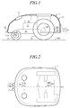
- FIG. 1 is a side view schematically illustrating the configuration of an autonomously navigating utility vehicle according to an embodiment of the present invention
- FIG. 2 is plan view of the same.
- the autonomously navigating utility vehicle of the present invention can be embodied in the form of various types of utility vehicle and particularly as a lawn mower for lawn or grass mowing work.
- the forward direction (longitudinal direction) of the utility vehicle in plan view and the vehicle width direction perpendicular to the forward direction are defined as the forward-rearward direction and the leftward-rightward direction, respectively, and the height direction of the utility vehicle is defined as the upward-downward direction.
- the configuration of the constituents is explained in line with these definitions.
- an autonomously navigating utility vehicle (hereinafter called simply “vehicle”) 1 is equipped with a body 10 having a chassis 11 and a frame 12, along with a pair of left and right front wheels 13 and a pair of left and right rear wheels 14 that support the body 10 above a ground surface GR so as to be capable of travel.
- the front wheels 13 are rotatably fastened through stays 11 a to the front end of the chassis 11.
- the rear wheels 14, which are greater in diameter than the front wheels 13, are rotatably fastened directly to the rear end of the chassis 11.
- the weight and size of the vehicle 1 are such that it can be transported by an operator.
- a vehicle 1 whose total length (forward-rearward direction length) is about 500 mm, total width about 300 mm, and height about 300 mm.
- a work unit 16 a work motor 17 for driving the work unit 16, travel motors (prime mover) 18 for driving the rear wheels 14, a battery charging unit 19 and a battery (secondary battery) 20 are deployed in an internal space 15 of the vehicle 1 enclosed by the chassis 11 and the frame 12.
- the work unit 16 comprises a rotor and blades attached to the rotor and has a substantially disk-like shape as a whole.
- a rotating shaft is installed vertically at the center of the rotor and the work unit 16 is configured to enable adjustment of the height of the blades above the ground GR through a height regulating mechanism 21 by the operator.
- the height regulating mechanism 21 is equipped with, for example, a screw operable by the operator.
- the work motor 17 is constituted by an electric motor installed above the work unit 16, and an output shaft thereof is connected to the rotating shaft of the rotor to rotate the blades unitarily with the rotor.
- the travel motors 18 comprise a pair of electric motors 18L and 18R installed on the right and left inner sides of the left and right rear wheels 14. Output shafts of the travel motors 18L and 18R are connected to rotating shafts of the left and right rear wheels 14, respectively, so as each to independently drive or rotate the left or right rear wheel 14.
- the vehicle 1 comprises the front wheels 13 as non-driven free wheels and the rear wheels 14 as driving wheels, and the travel motors 18L and 18R each independently rotates one of the rear wheels 14 normally (rotation to move forward) or reversely (rotation to move reverse). By establishing a difference between the rotating speeds of the left and right rear wheels 14, the vehicle 1 can be turned to an arbitrary direction.
- the vehicle 1 when the left and right rear wheels 14 are both rotated normally and the rotational speed of the right rear wheel 14 is greater than the rotational speed of the left rear wheel 14, the vehicle 1 turns left at a turning angle ⁇ in accordance with the speed difference. Conversely, when the rotational speed of the left rear wheel 14 is greater than the rotational speed of the right rear wheel 14, the vehicle 1 turns right at a turning angle ⁇ in accordance with the speed difference. When one of the left and right rear wheels 14 is rotated normally and the other reversely both at the same speed, the vehicle 1 turns on the spot.
- the charging unit 19 which includes an AC-DC converter, is connected by wires to charging terminals 22 provided at the front end of the frame 12 and is also connected by wires to the battery 20.
- the charging terminals 22 have contacts 22a, and the battery 20 can be charged by connecting the charging terminals 22 through the contacts 22a to a charging station 3 (charging device, see FIG. 5 ).
- the battery 20 is connected through wires to the work motor 17 and the travel motors 18, and the work motor 17 and the travel motors 18 are driven by power supplied from the battery 20 through drivers.
- FIG. 3 is a block diagram showing the configuration of the control apparatus of the vehicle 1 according to the present embodiment.
- an Electronic Control Unit (ECU) 40 is mounted on the vehicle 1.
- the ECU 40 has a microcomputer of a configuration including an arithmetic processing unit (CPU) and memories ROM, RAM and other peripheral circuits.
- the ECU 40 is connected with a group of sensors collectively designated by reference numeral 50 that detects various conditions of the vehicle 1, charging unit 19, battery 20, a group of switches 25, display unit 26, work motor 17 and travels motors 18 (18R, 18L).
- the group of sensors 50 includes a pair of magnetic sensors 51 (51R, 51L), an angular velocity sensor (turning angle sensor) 52, an acceleration sensor 53, an orientation sensor 54, a position sensor 55, a contact sensor 56, a pair of wheel speed sensors 57 (57R, 57L), and a voltage sensor 58.
- the magnetic sensors 51 i.e., 51R and 51L are installed laterally spaced apart on the front end of the vehicle 1. More specifically, as shown in FIG. 2 , the magnetic sensors 51R and 51L are installed laterally symmetrically with respect to a center line CL running in the straight forward direction along the widthwise center of the vehicle 1.
- the magnetic sensors 51 produces an output indicating magnitude of magnetic field (magnetic field strength (intensity) H).
- the angular velocity sensor 52 produces an output indicating angular velocity (yaw rate) occurring around a height direction (z-axis) of the vehicle 1, from which a turning angle ⁇ of the vehicle 1 around the z-axis can be calculated.
- the acceleration sensor 53 produces an output indicating acceleration acting on the vehicle 1 in the directions of three orthogonal axes (x-axis, ⁇ -axis, and z-axis).
- the contact sensor 56 produces an output of ON signal when the frame 12 is detached from the chassis 11 owing to contact with an obstacle or the like.
- Each of the pair of wheel speed sensors 57R, 57L produces an output indicating wheel speed of one of the left and right rear wheels 14, from which a travel distance of the vehicle 1 can be calculated.
- the voltage sensor 58 produces an output indicating a residual voltage of he battery 20.
- the switches 25 has various switches provided to be manipulatable by the operator and includes a main switch for inputting various commands, inter alia, start of vehicle 1 operation, and an emergency stop switch for stopping the vehicle 1 in an emergency.
- the display unit 26 has a display that shows various information to be supplied to the operator.
- the switches 25 and display unit 26 may be constituted by a touch panel.
- FIG. 4 is a diagram showing an example of a working area AR.
- the working area AR is, for example, delineated by a boundary wire 2 that constitutes a boundary line (L0) and is laid beforehand (e.g., buried a predetermined depth under the ground surface GR).
- a magnetic field is generated in the working area AR by passing electric current through the boundary wire 2.
- the charging station 3 for charging the battery 20 is situated above the boundary wire 2.
- the working area AR defines the travel range of the vehicle 1 and may include not only area(s) to be serviced but also area(s) not to be serviced.
- FIG. 5 is a diagram showing relation between distance d from the boundary wire 2 and magnetic field strength H.
- magnetic field strength H varies with distance d from the boundary wire 2. Specifically, magnetic field strength H is 0 above the boundary wire 2, positive inside the working area AR, and negative outside the same.
- the ECU 40 reads outputs of the magnetic sensors 51L and 51R, and when the output is minus, turns the vehicle 1 toward inside the working area AR at a random angle based on, for example, the output of the angular velocity sensor 52. As a result, work can be carried out inside the working area AR while the vehicle 1 is being driven (forward at random, for example).
- FIG. 6 is a block diagram showing a configuration of the charging station 3 installed on the boundary wire 2.
- the charging station 3 has a charger 30 connected through an outlet 32 to a commercial power supply 31, and terminals 33 and a station coil 34 connected to the charger 30.
- the charger 30 has an AC/AC converter 301, an ECU (electronic control unit) 302 that controls operation of the AC/AC converter 301, and a signal generator 303 that applies alternating current to the boundary wire 2 and station coil 34 to generate signals.
- ECU electronic control unit
- Alternating current from the commercial power supply 31 is stepped down to a suitable voltage by the AC/AC converter 301.
- the AC/AC converter 301 When the vehicle 1 returns to the charging station 3 and the contacts 22a of the terminals 22 of the vehicle 1 connect with the terminals 33, power stepped-down by the AC/AC converter 301 is supplied to the vehicle 1 to charge the battery 20.
- the station coil 34 is installed on the charging station 3 and a magnetic field is generated by current passing through the station coil 34. As shown in FIG. 4 , this magnetic field forms a charger detection zone 3a within a circle of about 1 m radius centered on the charging station 3. Entry of the vehicle 1 into the charger detection zone 3a is detected from the output of the magnetic sensors 51.
- the vehicle 1 operates in work mode, trace mode and return mode in response to control commands sent from the ECU 40 in accordance with programs prepared beforehand and memorized in the memory (ROM).
- work mode the vehicle 1 works (mows lawn or grass) while autonomously navigating in the working area AR.
- return mode the vehicle 1 is returned to the charging station 3 when the battery 20 requires charging.
- trace mode the vehicle 1 is driven along the boundary wire 2. Trace mode is executed before work mode to ascertain the working area AR.
- FIG. 7 is a diagram showing operation of the vehicle 1 in trace mode.
- the vehicle 1 in trace mode the vehicle 1 is driven by commands from the ECU 40 to circuit along the boundary wire 2 with one of the pair of magnetic sensors 51R and 51L (e.g., 51L) positioned inside the boundary wire 2 and so that the other magnetic sensor (e.g., 51R) moves above the boundary wire 2 in the direction of arrow A.
- the ECU 40 monitors output of the magnetic sensor 51R and controls operation of the travel motors 18L and 18R so that magnetic field strength H detected by the magnetic sensor 51R stays at 0.
- Trace mode is started from a state in which the terminals 22 of the vehicle 1 are connected to the terminals 33 of the charging station 3 and ends when the terminals 22 again connect to the terminals 33 after the vehicle 1 makes a circuit along the boundary wire 2.
- a turning angle ⁇ of the vehicle 1 at trace mode can be acquired by time-integrating the angular velocity detected from the output of the angular velocity sensor 52.
- a travel distance L of the vehicle 1 can be obtained by time-integrating the wheel speed detected from the output of the wheel speed sensor 57. Based on the turning angle ⁇ and travel distance L, the ECU 40 identifies a boundary line BL of the working area AR (in FIG. 4 ).
- the vehicle 1 can be returned to the charging station 3 constituting the target position.
- the vehicle 1 at position A in FIG. 4 is driven straight forward as indicated by arrow A1, turned toward the charging station 3 upon arriving at the boundary wire 2, and driven along the boundary wire 2 as indicated by arrow A2.
- the vehicle 1 at position B in FIG. 4 is driven straight forward as indicated by arrow B1, turned toward the charging station 3 upon arriving at the boundary wire 2, and driven along the boundary wire 2 as indicate by arrow B2.
- the vehicle 1 can be returned to the charging station 3 on the boundary wire 2.
- control apparatus is configured as follows in order to prevent occurrence of ruts and realize efficient return mode.
- the ECU 40 has a map generating unit 41, mode switching unit 42, a cell memorizing unit 43, a cell selecting unit 44, and a travel controlling unit 45.
- the map generating unit 41 generates a map of the working area AR (working area map MP) based on the working area boundary line BL identified in trace mode. Travel by trace mode is required only once after laying the boundary wire 2, and the working area map MP obtained at this time is stored in the RAM (memory) of the ECU 40.
- FIG. 8 is a diagram showing an example of the working area map MP.
- the working area map MP comprises a bitmap in which multiple square cells 61 corresponding to the working area AR are arrayed.
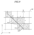
- FIG. 9 is a diagram showing an enlarged view of a portion of the working area map MP.
- the working area map MP is configured by arraying the square cells 61 of predetermined side length a (e.g., 200 mm) in a grid pattern within a horizontal plane including an X axis and a Y axis (XY plane).
- Each cell 61 includes position data relative to a predetermined position (origin, e.g., the charging station 3). Size of the cells 61 can be varied as appropriate and can, for example, be defined to coincide with working width of the work unit 16 (maximum outer diameter of blade).
- the mode switching unit 42 switches between work mode and return mode. For example, when voltage detected by the voltage sensor 58 falls to or below the predetermined value, indicating that the battery 20 requires charging, the mode switching unit 42 switches operating mode from work mode to return mode. On the other hand, when charging of the battery 20 is completed, it switches operating mode from return mode to work mode.
- the mode switching unit 42 can be configured to switch not only between work mode and return mode but also among trace mode, work mode and return mode.
- the cell memorizing unit 43 identifies each of the cells 61 on the working area map MP over which the vehicle 1 passes in work mode, i.e., identifies a series of cells 61a as a travel locus PA1 (shown in FIG. 8 ).
- the series of cells 61a is hereinafter referred to as "travel locus cells”.
- the unit 43 memorizes the identified travel locus cells 61a in association with sequentially assigned cell numbers n .
- cell number n of a starting cell 61 corresponding to at (or around) the location of the charging station 3 is assigned 0.
- a series of the travel locus cells 61a are assigned cell numbers n successively incremented by 1 along the travel locus PA1.
- the cell memorizing unit 43 first utilizes the output from the angular velocity sensor 52 to calculate a turning angle ⁇ of the vehicle 1 with respect to a reference line (e.g., X axis) every predetermined time interval ⁇ t (e.g., 100 ms). In addition, it utilizes outputs from the wheel speed sensors 57 to calculate a travel distance ⁇ L traveled by the vehicle 1 during predetermined time interval ⁇ t.
- a reference line e.g., X axis
- ⁇ t e.g. 100 ms
- the travel locus PA1 is obtained by sequentially connecting calculated moving points P with straight lines.
- a case may arise in work mode in which two (or more) parts of the travel locus PA1 cross each other, i.e., in which two of the travel locus cells 61a overlap.
- the cell memorizing unit 43 without incrementing the cell numbers n of the travel locus cells 61a, deletes all of the cell numbers n larger than an original cell number n. Travel locus cells 61a whose cell numbers n are deleted become just plain cells 61 not subject to memorizing by the cell memorizing unit 43. Numbering of travel locus cells 61a is then resumed starting from the overlapping travel locus cell 61a.
- the cell selecting unit 44 takes current (concerned) one of the travel locus cells 61a of the vehicle 1 as a beginning point to select (from among the travel locus cells 61a memorized in the cell memorizing unit 43) a new series of cells of sequentially smaller cell number n . They are hereinafter referred to as "return locus cells 61b".
- the return locus cells 61b are selected from among the cells 61 around current one (crossing point) of the travel locus cells 61a, e.g., from among a grid of eight cells 61 adjacent to the current one of the travel locus cells 61a in forward, backward, leftward, rightward and diagonal directions.
- the travel locus cells 61a are present in the grid of eight cells 61, the one with smallest cell number n is selected (more precisely the one whose cell number n is largest, but is smallest among eight is selected).
- a return route (hereinafter referred to as "PA2") of the vehicle 1 can be generated by connecting the return locus cells 61b selected in this manner with straight lines.
- the cell selecting unit 44 can select the return locus cells 61b from a grid of four cells adjacent to the travel locus cells 61a in forward, backward, leftward and rightward directions.
- FIG. 10 is a diagram showing an example of the return route PA2.
- the return route PA2 shown in FIG. 10 is generated using the travel locus PA1 of FIG. 8 illustrated in the left thereof.
- each of the travel locus cell 61a selected as the return locus cells 61b is neighbored by a single one of the travel locus cells 61a (not yet selected as the return locus cell 61b). Therefore, each of the travel locus cell 61a is converted as it is to the return locus cell 61b to enable generation of the return route PA2 by interconnecting the return locus cells 61b in order of selection (from larger to smaller cell number n ).
- the travel controlling unit 45 controls operation of the travel motors 18 so that the vehicle 1 docks with the charging station 3 to connect the terminals 22 to the terminals 33.
- FIGs. 11 and 12 are flowcharts showing an example of processing performed by the ECU 40.
- FIG. 11 shows an example of processing of travel route (return route) determination in work mode (work mode processing)
- FIG. 12 an example of processing in return mode (return mode processing).
- Work mode processing is started upon completion of charging the battery 20 after docking the vehicle 1 with the charging station 3.
- operation of the travel motors 18 is controlled by outputting control commands thereto through the motor drive drivers 18a to make vehicle 1 take attitude to work commencing (S: processing Step). Specifically, the vehicle 1 is controlled to back up to be disengaged from the charging station 3 and to turn toward inside the working area AR.
- operation of the work motor 17 is controlled by outputting control commands thereto through the work motor driver 17a to make the work unit 16 operate.
- operation of the travel motors 18 is controlled by outputting control commands thereto to make the vehicle 1 travel about the working area AR randomly and autonomously to perform work.
- S4 it is determined whether residual voltage of the battery 20 detected from the output of the voltage sensor 58 is equal to or greater than the predetermined value, i.e., whether charging of the battery 20 is unnecessary.
- the program goes to S5.
- S6 it is determined whether the vehicle 1 enters any cell 61 of a plurality of series of adjacent travel locus cell 61a of the working area map MP generated in advance by the map generating unit 41 based on the position of the vehicle 1 calculated in S5.
- the program returns back to S3 to continue the work.
- the program goes to S7, in which it is determined whether the concerned one (entered cell) of the travel locus cells 61a has already been assigned with the cell number n .
- the already assigned cell numbers n are deleted up to the current (concerned) cell number n .
- the cell numbers n from the original one at the overlapping position onward are deleted.
- S11 it is determined whether the vehicle 1 reaches the boundary wire 2 based on the output of the magnetic sensors 51.
- the program returns back to S3.
- the program goes to S12, in which operation of the travel motors 18 is controlled to make the vehicle 1 stop and turn toward inside the working area AR, whereafter the program returns to S3.
- the cell numbers n of the travel locus cells 61a on the working area map MP over which the vehicle 1 passes are assigned with the cell number n and memorized in the cell memorizing unit 43 to be utilized at return mode.
- Return mode processing is started when residual voltage of the battery 20 detected from the output of the voltage sensor 58 falls to or below the predetermined value. Driving of the work unit 16 is stopped at this time.
- operation of the travel motors 18 is controlled to make the vehicle 1 turn by 180 degrees. This is to first reverse the direction of the vehicle 1 in order to return it along the travel locus cells 61 a.
- operation of the travel motors 18 is controlled to make the vehicle 1 travel forward.
- a cell of smallest cell number n i.e., the return locus cells 61b are selected from among a plurality of series of the travel locus cells 61a around the vehicle 1 memorized in the cell memorizing unit 43.
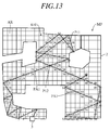
- FIGs. 13 and 14 are modifications on FIGs. 8 and 10 , respectively.
- FIG. 13 shows other examples of travel locus PA1 and
- FIG. 14 shows other example of the return route PA2.
- the cell memorizing unit 43 performs processing to sequentially assign cell numbers n to each of the cells 61 on the working area map MP over which the vehicle 1 passes, i.e., the travel locus cells 61a, and stores them as cell data (S8).
- n 55 to 58 are deleted without incrementing the cell number n to 59 (S9).
- the embodiment is configured to have an apparatus and method for controlling operation of an autonomously navigating utility vehicle (1) equipped with a prime mover (18) powered by a battery (20) to travel about a working area (AR) in order to perform work autonomously, comprising: a mode switching unit (42) that is configured to switch operating mode between work mode for making the vehicle autonomously travel and perform work in the working area and return mode for making the vehicle return to a charging device (3) located at the working area in order to charge the battery (20); a position detector (52, 57, S5) that is configured to detect position of the vehicle on a map (MP) of the working area that is divided into an array of a plurality of cells (61); a cell memorizing unit (43, S8) that is configured to identify a series of cells (61a) on which the vehicle has traveled in the work mode from among the plurality of cells based on the position of the vehicle detected by the position detector, assign cell numbers (n) successively to the series of cells, and memorize the series of cells in association with the assigned cell numbers, the
- the travel locus cells 61 a on the map MP of the working area map MP on which the vehicle 1 travels about are memorized in association with sequentially assigned numbers, the travel locus cells 61a are sequentially selected from among the stored travel locus cells 61 a so that the cell number n become smaller, and the vehicle 1 returns following the selected cells (return locus cells 61b).
- the vehicle 1 at position 15 in FIG. 14 returns along the return route PA2 inside the working area AR.
- the return path becomes short and efficient return operation can be achieved.
- occurrence of ruts can be prevented because the return route PA2 constantly changes in accordance with the travel locus PA1.
- the cell memorizing unit deletes the cell numbers that are larger than a cell number of the one, and resumes assigning cell numbers starting from the cell number of the one (S9 - S10).
- the part (loop) 610 of the travel locus cells 61a is therefore deleted when the travel locus PA1 intersect, the return locus cells 61b selected from the travel locus cells 61a have no intersection or crossing ( FIGs. 10, 14 ). Return route PA2 can therefore be shortened and efficient return operation realized. Moreover, by deleting some of the cell numbers n , the number of travel locus cells 61a stored by the cell memorizing unit 43 can be reduced and memory capacity saved.
- the cell selecting unit selects a cell whose cell number is smallest among the plurality of cells adjacent to the current cell as the return locus cell (S23).
- the position detector comprises an angular velocity sensor (52) that is installed on the vehicle and produces an output indicating an angular velocity occurring around the vehicle, and a travel distance detector (57) that is installed on the vehicle and produces an output indicating a travel distance of the vehicle.
- the apparatus can be configured overall at low cost.
- the travel locus PA1 of the vehicle 1 is identified and return operation of the vehicle 1 is controlled in cell units, which makes calculation of the exact position of the vehicle 1 unnecessary and enables the controller to be simply configured.
- the cell memorizing unit 43 memorizes the cell numbers n as attribute data of the cells 61 and the cell selecting unit 44 selects return locus cells 61b using the cell numbers n , thus facilitating processing by the ECU 40.
- the orientation detector for detecting vehicle orientation it is possible to use the angular velocity sensor 52 instead of the orientation sensor 54 or together with the orientation sensor 54.
- the present embodiment is configured such that the vehicle 1 is driven by the prime mover comprising a pair of travel motors 18L, 18R, it may be configured such that the vehicle 1 can be driven by other prime mover such as an internal combustion engine.
- a cell memorizing unit (43) identifying a series of cells on which the vehicle has traveled in the work mode, assigning cell numbers successively to the series of cells, and memorizing the series of cells in association with the assigned cell numbers, the series of cells starting from the charging device to the current cell of the vehicle, a cell selecting unit (44) selecting a return locus cell from among the series of cells in the return mode, the return locus cell being adjacent to the current cell, a cell number of the return locus cell being smaller than a cell number of the current cell, and a travel controlling unit (45) controlling the vehicle to travel on the return locus cell to return to the charging device.
Landscapes
- Engineering & Computer Science (AREA)
- Radar, Positioning & Navigation (AREA)
- Physics & Mathematics (AREA)
- Aviation & Aerospace Engineering (AREA)
- Automation & Control Theory (AREA)
- General Physics & Mathematics (AREA)
- Remote Sensing (AREA)
- Life Sciences & Earth Sciences (AREA)
- Environmental Sciences (AREA)
- Electromagnetism (AREA)
- Medical Informatics (AREA)
- Game Theory and Decision Science (AREA)
- Evolutionary Computation (AREA)
- Health & Medical Sciences (AREA)
- Artificial Intelligence (AREA)
- Business, Economics & Management (AREA)
- Control Of Position, Course, Altitude, Or Attitude Of Moving Bodies (AREA)
- Electric Propulsion And Braking For Vehicles (AREA)
Abstract
Description
- This invention relates to a control apparatus for an autonomous navigating utility vehicle that autonomously navigates and performs lawn mowing and/or other tasks in a working area.
- Control apparatuses are known that control an autonomously navigating utility vehicle equipped with electric motors and a battery so as to perform a task while autonomously traveling in a working area delineated by a boundary wire as taught by Japanese Laid-Open Patent Application No.
2013-164742 - However, the driving of the utility vehicle along the boundary wire by the control apparatus described in the reference tends to produce ruts because frequency of passage along the same paths is high. Moreover, a path to a charging station becomes long, making it difficult to achieve efficient return operation of the utility vehicle.
- According to an aspect of the present invention, there is provided an apparatus for controlling operation of an autonomously navigating utility vehicle equipped with a prime mover powered by a battery to travel about a working area in order to perform work autonomously, comprising: a mode switching unit that is configured to switch operating mode between work mode for making the vehicle autonomously travel and perform work in the working area and return mode for making the vehicle return to a charging device located at the working area in order to charge the battery; a position detector that is configured to detect position of the vehicle on a map of the working area that is divided into an array of a plurality of cells; a cell memorizing unit that is configured to identify a series of cells on which the vehicle has traveled in the work mode from among the plurality of cells based on the position of the vehicle detected by the position detector, assign cell numbers successively to the series of cells, and memorize the series of cells in association with the assigned cell numbers, the series of cells starting from a starting cell at or around a location of the charging device to a current cell at which the position of the vehicle is detected by the position detector; a cell selecting unit that is configured to select a return locus cell to which the vehicle is to move from the current cell from among the series of cells memorized by the cell memorizing unit, when the operating mode is switched from the work mode to the return mode by the mode switching unit, the return locus cell being adjacent to the current cell, a cell number of the return locus cell being smaller than a cell number of the current cell; and a travel controlling unit that is configured to control operation of the prime mover to make the vehicle travel on the return locus cell selected by the cell selecting unit to return to the charging device.
- The objects, features, and advantages of the present invention will become clearer from the following description of embodiments in relation to the attached drawings, in which:
-
FIG. 1 is a side view schematically illustrating configuration of an autonomously navigating utility vehicle according to an embodiment of this invention; -
FIG. 2 is a plan view schematically illustrating the configuration of the utility vehicle according to the embodiment; -
FIG. 3 is a block diagram showing the configuration of the control apparatus of the vehicle according to the present embodiment including an ECU; -
FIG. 4 is a diagram showing an example of a working area; -
FIG. 5 is a diagram showing relation between distance from the boundary wire and magnetic field strength; -
FIG. 6 is a block diagram showing a configuration of the charging station installed on the boundary wire ofFIG. 4 ; -
FIG. 7 is a diagram showing operation of the utility vehicle in trace mode; -
FIG. 8 is a diagram showing an example of a working area map; -
FIG. 9 is a diagram showing an enlarged view of a portion of the working area map ofFIG. 8 ; -
FIG. 10 is a diagram showing an example of a return route selected by a cell selecting unit ofFIG. 3 ; -
FIG. 11 is a flowchart showing processing of travel route (return route) determination in work mode; -
FIG. 12 is a flowchart showing processing in return mode referred to in the flowchart ofFIG. 11 ; -
FIG. 13 is a diagram showing modification ofFIGs. 8 ; and -
FIG. 14 is a diagram showing modifications onFIG. 10 . - An embodiment of the present invention is explained with reference to
FIGs. 1 to 14 in the following.FIG. 1 is a side view schematically illustrating the configuration of an autonomously navigating utility vehicle according to an embodiment of the present invention, andFIG. 2 is plan view of the same. - The autonomously navigating utility vehicle of the present invention can be embodied in the form of various types of utility vehicle and particularly as a lawn mower for lawn or grass mowing work. In the following, the forward direction (longitudinal direction) of the utility vehicle in plan view and the vehicle width direction perpendicular to the forward direction are defined as the forward-rearward direction and the leftward-rightward direction, respectively, and the height direction of the utility vehicle is defined as the upward-downward direction. The configuration of the constituents is explained in line with these definitions.
- As shown in
FIGs. 1 and 2 , an autonomously navigating utility vehicle (hereinafter called simply "vehicle") 1 is equipped with abody 10 having achassis 11 and aframe 12, along with a pair of left and rightfront wheels 13 and a pair of left and rightrear wheels 14 that support thebody 10 above a ground surface GR so as to be capable of travel. - The
front wheels 13 are rotatably fastened throughstays 11 a to the front end of thechassis 11. Therear wheels 14, which are greater in diameter than thefront wheels 13, are rotatably fastened directly to the rear end of thechassis 11. The weight and size of thevehicle 1 are such that it can be transported by an operator. As an example can be cited avehicle 1 whose total length (forward-rearward direction length) is about 500 mm, total width about 300 mm, and height about 300 mm. - A
work unit 16, awork motor 17 for driving thework unit 16, travel motors (prime mover) 18 for driving therear wheels 14, abattery charging unit 19 and a battery (secondary battery) 20 are deployed in aninternal space 15 of thevehicle 1 enclosed by thechassis 11 and theframe 12. - The
work unit 16 comprises a rotor and blades attached to the rotor and has a substantially disk-like shape as a whole. A rotating shaft is installed vertically at the center of the rotor and thework unit 16 is configured to enable adjustment of the height of the blades above the ground GR through aheight regulating mechanism 21 by the operator. The height regulatingmechanism 21 is equipped with, for example, a screw operable by the operator. Thework motor 17 is constituted by an electric motor installed above thework unit 16, and an output shaft thereof is connected to the rotating shaft of the rotor to rotate the blades unitarily with the rotor. - The
travel motors 18 comprise a pair ofelectric motors rear wheels 14. Output shafts of thetravel motors rear wheels 14, respectively, so as each to independently drive or rotate the left or rightrear wheel 14. In other words, thevehicle 1 comprises thefront wheels 13 as non-driven free wheels and therear wheels 14 as driving wheels, and thetravel motors rear wheels 14 normally (rotation to move forward) or reversely (rotation to move reverse). By establishing a difference between the rotating speeds of the left and rightrear wheels 14, thevehicle 1 can be turned to an arbitrary direction. - For example, when the left and right
rear wheels 14 are both rotated normally and the rotational speed of the rightrear wheel 14 is greater than the rotational speed of the leftrear wheel 14, thevehicle 1 turns left at a turning angle θ in accordance with the speed difference. Conversely, when the rotational speed of the leftrear wheel 14 is greater than the rotational speed of the rightrear wheel 14, thevehicle 1 turns right at a turning angle θ in accordance with the speed difference. When one of the left and rightrear wheels 14 is rotated normally and the other reversely both at the same speed, thevehicle 1 turns on the spot. - The
charging unit 19, which includes an AC-DC converter, is connected by wires to chargingterminals 22 provided at the front end of theframe 12 and is also connected by wires to thebattery 20. Thecharging terminals 22 havecontacts 22a, and thebattery 20 can be charged by connecting thecharging terminals 22 through thecontacts 22a to a charging station 3 (charging device, seeFIG. 5 ). Thebattery 20 is connected through wires to thework motor 17 and thetravel motors 18, and thework motor 17 and thetravel motors 18 are driven by power supplied from thebattery 20 through drivers. -
FIG. 3 is a block diagram showing the configuration of the control apparatus of thevehicle 1 according to the present embodiment. As shown inFIG. 3 , an Electronic Control Unit (ECU) 40 is mounted on thevehicle 1. The ECU 40 has a microcomputer of a configuration including an arithmetic processing unit (CPU) and memories ROM, RAM and other peripheral circuits. - The ECU 40 is connected with a group of sensors collectively designated by
reference numeral 50 that detects various conditions of thevehicle 1,charging unit 19,battery 20, a group ofswitches 25,display unit 26,work motor 17 and travels motors 18 (18R, 18L). The group ofsensors 50 includes a pair of magnetic sensors 51 (51R, 51L), an angular velocity sensor (turning angle sensor) 52, anacceleration sensor 53, anorientation sensor 54, aposition sensor 55, acontact sensor 56, a pair of wheel speed sensors 57 (57R, 57L), and avoltage sensor 58. - The
magnetic sensors 51, i.e., 51R and 51L are installed laterally spaced apart on the front end of thevehicle 1. More specifically, as shown inFIG. 2 , themagnetic sensors vehicle 1. Themagnetic sensors 51 produces an output indicating magnitude of magnetic field (magnetic field strength (intensity) H). - The
angular velocity sensor 52 produces an output indicating angular velocity (yaw rate) occurring around a height direction (z-axis) of thevehicle 1, from which a turning angle θ of thevehicle 1 around the z-axis can be calculated. - The
acceleration sensor 53 produces an output indicating acceleration acting on thevehicle 1 in the directions of three orthogonal axes (x-axis, γ-axis, and z-axis). - The
contact sensor 56 produces an output of ON signal when theframe 12 is detached from thechassis 11 owing to contact with an obstacle or the like. Each of the pair ofwheel speed sensors rear wheels 14, from which a travel distance of thevehicle 1 can be calculated. Thevoltage sensor 58 produces an output indicating a residual voltage of hebattery 20. - The
switches 25 has various switches provided to be manipulatable by the operator and includes a main switch for inputting various commands, inter alia, start ofvehicle 1 operation, and an emergency stop switch for stopping thevehicle 1 in an emergency. - The
display unit 26 has a display that shows various information to be supplied to the operator. Theswitches 25 anddisplay unit 26 may be constituted by a touch panel. - The
vehicle 1 configured as described above performs a task while autonomously navigating within a predefined working area.FIG. 4 is a diagram showing an example of a working area AR. The working area AR is, for example, delineated by aboundary wire 2 that constitutes a boundary line (L0) and is laid beforehand (e.g., buried a predetermined depth under the ground surface GR). A magnetic field is generated in the working area AR by passing electric current through theboundary wire 2. The chargingstation 3 for charging thebattery 20 is situated above theboundary wire 2. The working area AR defines the travel range of thevehicle 1 and may include not only area(s) to be serviced but also area(s) not to be serviced. -
FIG. 5 is a diagram showing relation between distance d from theboundary wire 2 and magnetic field strength H. As indicated inFIG. 6 , magnetic field strength H varies with distance d from theboundary wire 2. Specifically, magnetic field strength H is 0 above theboundary wire 2, positive inside the working area AR, and negative outside the same. When work is in progress, theECU 40 reads outputs of themagnetic sensors vehicle 1 toward inside the working area AR at a random angle based on, for example, the output of theangular velocity sensor 52. As a result, work can be carried out inside the working area AR while thevehicle 1 is being driven (forward at random, for example). -
FIG. 6 is a block diagram showing a configuration of the chargingstation 3 installed on theboundary wire 2. As shown inFIG. 6 , the chargingstation 3 has acharger 30 connected through anoutlet 32 to acommercial power supply 31, andterminals 33 and astation coil 34 connected to thecharger 30. Thecharger 30 has an AC/AC converter 301, an ECU (electronic control unit) 302 that controls operation of the AC/AC converter 301, and asignal generator 303 that applies alternating current to theboundary wire 2 andstation coil 34 to generate signals. - Alternating current from the
commercial power supply 31 is stepped down to a suitable voltage by the AC/AC converter 301. When thevehicle 1 returns to the chargingstation 3 and thecontacts 22a of theterminals 22 of thevehicle 1 connect with theterminals 33, power stepped-down by the AC/AC converter 301 is supplied to thevehicle 1 to charge thebattery 20. Thestation coil 34 is installed on the chargingstation 3 and a magnetic field is generated by current passing through thestation coil 34. As shown inFIG. 4 , this magnetic field forms acharger detection zone 3a within a circle of about 1 m radius centered on the chargingstation 3. Entry of thevehicle 1 into thecharger detection zone 3a is detected from the output of themagnetic sensors 51. - In the present embodiment, the
vehicle 1 operates in work mode, trace mode and return mode in response to control commands sent from theECU 40 in accordance with programs prepared beforehand and memorized in the memory (ROM). In work mode, thevehicle 1 works (mows lawn or grass) while autonomously navigating in the working area AR. In return mode, thevehicle 1 is returned to the chargingstation 3 when thebattery 20 requires charging. In trace mode, thevehicle 1 is driven along theboundary wire 2. Trace mode is executed before work mode to ascertain the working area AR. -
FIG. 7 is a diagram showing operation of thevehicle 1 in trace mode. As shown inFIG. 7 , in trace mode thevehicle 1 is driven by commands from theECU 40 to circuit along theboundary wire 2 with one of the pair ofmagnetic sensors boundary wire 2 and so that the other magnetic sensor (e.g., 51R) moves above theboundary wire 2 in the direction of arrow A. Specifically, theECU 40 monitors output of themagnetic sensor 51R and controls operation of thetravel motors magnetic sensor 51R stays at 0. - For example, when magnetic field strength H detected from the output of the
magnetic sensor 51R becomes positive, thevehicle 1 is turned rightward by deceleratingright travel motor 18R and acceleratingleft travel motor 18L. On the other hand, when magnetic field strength H detected from the output of themagnetic sensor 51R becomes negative, thevehicle 1 is turned leftward by accelerating theright travel motor 18R and decelerating theleft travel motor 18L. As a result, the rightmagnetic sensor 51R is brought near theboundary wire 2 and magnetic field strength H detected by the rightmagnetic sensor 51 R is maintained at 0. - Trace mode is started from a state in which the
terminals 22 of thevehicle 1 are connected to theterminals 33 of the chargingstation 3 and ends when theterminals 22 again connect to theterminals 33 after thevehicle 1 makes a circuit along theboundary wire 2. A turning angle θ of thevehicle 1 at trace mode can be acquired by time-integrating the angular velocity detected from the output of theangular velocity sensor 52. A travel distance L of thevehicle 1 can be obtained by time-integrating the wheel speed detected from the output of thewheel speed sensor 57. Based on the turning angle θ and travel distance L, theECU 40 identifies a boundary line BL of the working area AR (inFIG. 4 ). - As regards return mode, if the
vehicle 1 is trace-driven along theboundary wire 2, it can be returned to the chargingstation 3 constituting the target position. For example, thevehicle 1 at position A inFIG. 4 is driven straight forward as indicated by arrow A1, turned toward the chargingstation 3 upon arriving at theboundary wire 2, and driven along theboundary wire 2 as indicated by arrow A2. Or thevehicle 1 at position B inFIG. 4 is driven straight forward as indicated by arrow B1, turned toward the chargingstation 3 upon arriving at theboundary wire 2, and driven along theboundary wire 2 as indicate by arrow B2. As a result, thevehicle 1 can be returned to the chargingstation 3 on theboundary wire 2. - However, when the
vehicle 1 is returned by trace-driving, distance traveled during return becomes long. As a result, time required for return increases and working efficiency declines. Moreover, thevehicle 1 passes along the same route (above the boundary wire 2) during every return, so that ruts tend to form along theboundary wire 2. Therefore, the control apparatus according to the present embodiment is configured as follows in order to prevent occurrence of ruts and realize efficient return mode. - As shown in
FIG. 3 , as functional constituents related mainly to return mode, theECU 40 has amap generating unit 41,mode switching unit 42, acell memorizing unit 43, acell selecting unit 44, and atravel controlling unit 45. - The
map generating unit 41 generates a map of the working area AR (working area map MP) based on the working area boundary line BL identified in trace mode. Travel by trace mode is required only once after laying theboundary wire 2, and the working area map MP obtained at this time is stored in the RAM (memory) of theECU 40. -
FIG. 8 is a diagram showing an example of the working area map MP. The working area map MP comprises a bitmap in which multiplesquare cells 61 corresponding to the working area AR are arrayed. -
FIG. 9 is a diagram showing an enlarged view of a portion of the working area map MP. InFIG. 9 , the working area map MP is configured by arraying thesquare cells 61 of predetermined side length a (e.g., 200 mm) in a grid pattern within a horizontal plane including an X axis and a Y axis (XY plane). Eachcell 61 includes position data relative to a predetermined position (origin, e.g., the charging station 3). Size of thecells 61 can be varied as appropriate and can, for example, be defined to coincide with working width of the work unit 16 (maximum outer diameter of blade). - The
mode switching unit 42 switches between work mode and return mode. For example, when voltage detected by thevoltage sensor 58 falls to or below the predetermined value, indicating that thebattery 20 requires charging, themode switching unit 42 switches operating mode from work mode to return mode. On the other hand, when charging of thebattery 20 is completed, it switches operating mode from return mode to work mode. Alternatively, themode switching unit 42 can be configured to switch not only between work mode and return mode but also among trace mode, work mode and return mode. - The
cell memorizing unit 43 identifies each of thecells 61 on the working area map MP over which thevehicle 1 passes in work mode, i.e., identifies a series ofcells 61a as a travel locus PA1 (shown inFIG. 8 ). The series ofcells 61a is hereinafter referred to as "travel locus cells". Theunit 43 memorizes the identifiedtravel locus cells 61a in association with sequentially assigned cell numbers n. As thevehicle 1 travels relative to the chargingstation 3 as an origin in work mode, cell number n of a startingcell 61 corresponding to at (or around) the location of the chargingstation 3 is assigned 0. Thereafter, as shown inFIG. 8 , a series of thetravel locus cells 61a are assigned cell numbers n successively incremented by 1 along the travel locus PA1. - This point will be explained in detail with reference to
FIG. 9 . Thecell memorizing unit 43 first utilizes the output from theangular velocity sensor 52 to calculate a turning angle Δθ of thevehicle 1 with respect to a reference line (e.g., X axis) every predetermined time interval Δt (e.g., 100 ms). In addition, it utilizes outputs from thewheel speed sensors 57 to calculate a travel distance ΔL traveled by thevehicle 1 during predetermined time interval Δt. Next, it calculate the XY-plane position coordinates (X, Y) of moving point P of thevehicle 1 relative to a reference position (e.g., location of the charging station 3) at every predetermined time interval Δt based on the calculated turning angle Δθ and travel distance ΔL in equation (I) below to.
- As shown in
FIG. 9 , the travel locus PA1 is obtained by sequentially connecting calculated moving points P with straight lines. Thecell memorizing unit 43 sequentially assigns cell numbers n increased in increments of 1 (n= q, q+1, q+2, ...) to thetravel locus cells 61a (hatched portions) included in the travel locus PA1 and memorizes them in memory (RAM). Namely, the cell numbers n are memorized together with position data as cell-specific data of thetravel locus cells 61a. - Regarding this aspect, as shown at point P1 in
FIG. 8 , a case may arise in work mode in which two (or more) parts of the travel locus PA1 cross each other, i.e., in which two of thetravel locus cells 61a overlap. In such a case, without incrementing the cell numbers n of thetravel locus cells 61a, thecell memorizing unit 43 deletes all of the cell numbers n larger than an original cell number n.Travel locus cells 61a whose cell numbers n are deleted become justplain cells 61 not subject to memorizing by thecell memorizing unit 43. Numbering oftravel locus cells 61a is then resumed starting from the overlappingtravel locus cell 61a. - In the example of
FIG. 8 , two parts of the travel locus PA1 cross each other at point P1 ontravel locus cell 61 a with cell number n=7. Therefore, cell numbers n = 8 to 61 are all deleted. This converts a part orloop 610 oftravel locus cells 61a (group 610 oftravel locus cells 61 a) toplain cells 61 having no cell numbers n. Then, starting from the concerned onetravel locus cell 61 a with cell number n=7, the cell numbers n (=8, 9 ...) are assigned sequentially as shown in the left of the figure. - When the
mode switching unit 42 switches operating mode from work mode to return mode, thecell selecting unit 44 takes current (concerned) one of thetravel locus cells 61a of thevehicle 1 as a beginning point to select (from among thetravel locus cells 61a memorized in the cell memorizing unit 43) a new series of cells of sequentially smaller cell number n. They are hereinafter referred to as "return locus cells 61b". - The
return locus cells 61b are selected from among thecells 61 around current one (crossing point) of thetravel locus cells 61a, e.g., from among a grid of eightcells 61 adjacent to the current one of thetravel locus cells 61a in forward, backward, leftward, rightward and diagonal directions. When two or more of thetravel locus cells 61a are present in the grid of eightcells 61, the one with smallest cell number n is selected (more precisely the one whose cell number n is largest, but is smallest among eight is selected). A return route (hereinafter referred to as "PA2") of thevehicle 1 can be generated by connecting thereturn locus cells 61b selected in this manner with straight lines. Alternatively, thecell selecting unit 44 can select thereturn locus cells 61b from a grid of four cells adjacent to thetravel locus cells 61a in forward, backward, leftward and rightward directions. -
FIG. 10 is a diagram showing an example of the return route PA2. The return route PA2 shown inFIG. 10 is generated using the travel locus PA1 ofFIG. 8 illustrated in the left thereof. In the example ofFIG. 10 , each of thetravel locus cell 61a selected as thereturn locus cells 61b is neighbored by a single one of thetravel locus cells 61a (not yet selected as thereturn locus cell 61b). Therefore, each of thetravel locus cell 61a is converted as it is to thereturn locus cell 61b to enable generation of the return route PA2 by interconnecting thereturn locus cells 61b in order of selection (from larger to smaller cell number n). - The
travel controlling unit 45 controls operation of thetravel motors 18 by outputting control commands thereto on the basis of outputs of theangular velocity sensor 52 andwheel speed sensors 57 to make thevehicle 1 travel along thereturn locus cells 61b selected by thecell selecting unit 44. Namely, it drives thevehicle 1 toward the chargingstation 3 so that cell numbers n ofreturn locus cells 61b passed through by thevehicle 1 decrease successively toward the starting cell whose cell number n =0. When themagnetic sensors 51 installed on thevehicle 1 enter thecharger detection zone 3a and detect the chargingstation 3, thetravel controlling unit 45 controls operation of thetravel motors 18 so that thevehicle 1 docks with the chargingstation 3 to connect theterminals 22 to theterminals 33. - Now follows a concrete explanation of processing performed in the
ECU 40.FIGs. 11 and12 are flowcharts showing an example of processing performed by theECU 40.FIG. 11 shows an example of processing of travel route (return route) determination in work mode (work mode processing) andFIG. 12 an example of processing in return mode (return mode processing). Work mode processing is started upon completion of charging thebattery 20 after docking thevehicle 1 with the chargingstation 3. - First, in S1, operation of the
travel motors 18 is controlled by outputting control commands thereto through the motor drive drivers 18a to makevehicle 1 take attitude to work commencing (S: processing Step). Specifically, thevehicle 1 is controlled to back up to be disengaged from the chargingstation 3 and to turn toward inside the working area AR. - Next, in S2, operation of the
work motor 17 is controlled by outputting control commands thereto through the work motor driver 17a to make thework unit 16 operate. Then, in S3, operation of thetravel motors 18 is controlled by outputting control commands thereto to make thevehicle 1 travel about the working area AR randomly and autonomously to perform work. - Next, in S4, it is determined whether residual voltage of the
battery 20 detected from the output of thevoltage sensor 58 is equal to or greater than the predetermined value, i.e., whether charging of thebattery 20 is unnecessary. When the result in S4 is YES, the program goes to S5. - In S5, the turning angle θ detected from the output of the
angular velocity sensor 52 and travel distance ΔL detected from the output of thewheel speed sensors 57 are substituted into the aforesaid equations (I) to calculate the position coordinates (X, Y) of thevehicle 1, i.e., the position of thevehicle 1 is detected. - Next, in S6, it is determined whether the
vehicle 1 enters anycell 61 of a plurality of series of adjacenttravel locus cell 61a of the working area map MP generated in advance by themap generating unit 41 based on the position of thevehicle 1 calculated in S5. When the result in S6 is NO, the program returns back to S3 to continue the work. - On the contrary, when the result in S6 is YES, the program goes to S7, in which it is determined whether the concerned one (entered cell) of the
travel locus cells 61a has already been assigned with the cell number n. When the result in S7 is NO, the program goes to S8, in which a cell number n (= q + 1) is obtained by adding 1 to the largest cell number n (= q) in the memorized data up to that time, and is assigned to the concerned one as new cell data of thetravel locus cells 61a. That is, the cell number n is incremented and is memorized. - On the other hand, when the result in S7 is YES, meaning that the concerned one of the
travel locus cells 61a has already been assigned with the cell number n, i.e., when thevehicle 1 passes through any of overlappingtravel locus cells 61a, the program goes to S9. - In S9, the already assigned cell numbers n are deleted up to the current (concerned) cell number n. Namely, the cell numbers n from the original one at the overlapping position onward are deleted. In the example of
FIG. 8 , the cell numbers n = 7 to 61 are deleted. This means to exclude thepart 610 of thetravel locus cells 61 a from thecell memorizing unit 43. Next, in S10, the current (concerned) one of thetravel locus cells 61a is assigned the same cell number n as the original one (i.e., n=7 in the example ofFIG. 8 ) and is memorized in memory. - Next, in S11, it is determined whether the
vehicle 1 reaches theboundary wire 2 based on the output of themagnetic sensors 51. When the result in S11 is NO, the program returns back to S3. On the other hand, when the result in S11 is YES, the program goes to S12, in which operation of thetravel motors 18 is controlled to make thevehicle 1 stop and turn toward inside the working area AR, whereafter the program returns to S3. - Owing to the aforesaid work mode processing, the cell numbers n of the
travel locus cells 61a on the working area map MP over which thevehicle 1 passes are assigned with the cell number n and memorized in thecell memorizing unit 43 to be utilized at return mode. - In the flowchart of
FIG. 11 , when the result in S4 is NO, the program goes to S21 ofFIG. 12 because thebattery 20 requires charging. - Now follows an explanation of return mode processing shown in
FIG. 12 . - Return mode processing is started when residual voltage of the
battery 20 detected from the output of thevoltage sensor 58 falls to or below the predetermined value. Driving of thework unit 16 is stopped at this time. - First, in S21, operation of the
travel motors 18 is controlled to make thevehicle 1 turn by 180 degrees. This is to first reverse the direction of thevehicle 1 in order to return it along thetravel locus cells 61 a. Next, in S22, operation of thetravel motors 18 is controlled to make thevehicle 1 travel forward. - Next, in S23, a cell of smallest cell number n, i.e., the
return locus cells 61b are selected from among a plurality of series of thetravel locus cells 61a around thevehicle 1 memorized in thecell memorizing unit 43. - Next, in S24, operation of the
travel motors 18 is controlled to make thevehicle 1 turn toward the selectedreturn locus cells 61b. Then, in S25, it is determined whether the chargingstation 3 is detected from the output of themagnetic sensors 51, i.e., whether thevehicle 1 enters thecharger detection zone 3a. - When the result in NO, the program returns to S22. On the contract, when the result in S25 is YES, the program goes to S26, in which operation of the
travel motors 18 is controlled to make thevehicle 1 commence docking operation for docking thevehicle 1 with the chargingstation 3 and connect theterminals 22 to theterminals 33. -
FIGs. 13 and14 are modifications onFIGs. 8 and10 , respectively.FIG. 13 shows other examples of travel locus PA1 andFIG. 14 shows other example of the return route PA2. - As shown in
FIG. 13 , in random driving mode thevehicle 1 changes direction every time it arrives at theboundary wire 2 so as to drive forward randomly within the working area AR (S3, S12). At this time, thecell memorizing unit 43 performs processing to sequentially assign cell numbers n to each of thecells 61 on the working area map MP over which thevehicle 1 passes, i.e., thetravel locus cells 61a, and stores them as cell data (S8). - When, at position P11 in
FIG. 13 , for example, thevehicle 1 again passes across one of thetravel locus cells 61a already assigned the cell number n (=55), n = 55 to 58 are deleted without incrementing the cell number n to 59 (S9). The original cell number n (=55) is then assigned to the concerned one of thetravel locus cells 61a of position P11 (S10) and incrementing is resumed. Therefore, each of thetravel locus cells 61 a is memorized in association with a single cell number n. - On the other hand, when two parts of the travel locus PA1 intersect each other at, for example, position P12 in
FIG. 13 , all of the original cell number n at the intersection or crossing (=34) and later cell numbers n (= 34 to 47) are deleted (S9). This converts a loop of thetravel locus cells 61a assigned n = 34 to 47 (part orseries 610 oftravel locus cells 61a) toplain cells 61 having no cell numbers n and deletes them from thecell memorizing unit 43. Also in this case, incrementing is resumed starting from the original cell number n (=34) (S10). - As shown in
FIG. 14 , in return mode, thecell selecting unit 44 performs processing whereby any of thereturn locus cells 61b of decreasing cell number n toward the starting cell whose cell number n = 0 are sequentially selected from among the series of thetravel locus cells 61a, and thetravel controlling unit 45 performs processing whereby thevehicle 1 drives along the selectedreturn locus cells 61b (S22, S23, S24). - For example, consider the case where at
position 21 inFIG. 14 one of thereturn locus cells 61b of cell number n=16 is neighbored by multipletravel locus cells 61a of smaller cell number n than this of thereturn locus cells 61b, namely, by thetravel locus cells 61a of n = 13, 14, 15. In this case, thecell selecting unit 44 performs processing whereby one of thetravel locus cells 61a of smallest cell number n (=13) is selected as thereturn locus cells 61b (S23). Therefore, thevehicle 1 does not pass across alltravel locus cells 61 a but can return to the chargingstation 3 by a shorter one of the return route PA2. - As stated above, the embodiment is configured to have an apparatus and method for controlling operation of an autonomously navigating utility vehicle (1) equipped with a prime mover (18) powered by a battery (20) to travel about a working area (AR) in order to perform work autonomously, comprising: a mode switching unit (42) that is configured to switch operating mode between work mode for making the vehicle autonomously travel and perform work in the working area and return mode for making the vehicle return to a charging device (3) located at the working area in order to charge the battery (20); a position detector (52, 57, S5) that is configured to detect position of the vehicle on a map (MP) of the working area that is divided into an array of a plurality of cells (61); a cell memorizing unit (43, S8) that is configured to identify a series of cells (61a) on which the vehicle has traveled in the work mode from among the plurality of cells based on the position of the vehicle detected by the position detector, assign cell numbers (n) successively to the series of cells, and memorize the series of cells in association with the assigned cell numbers, the series of cells starting from a starting cell at or around a location of the charging device to a current cell at which the position of the vehicle is detected by the position detector; a cell selecting unit (44, S23) that is configured to select a return locus cell (61b) to which the vehicle is to move from the current cell from among the series of cells memorized by the cell memorizing unit, when the operating mode is switched from the work mode to the return mode by the mode switching unit, the return locus cell being adjacent to the current cell, a cell number of the return locus cell being smaller than a cell number of the current cell; and a travel controlling unit (45, S24) that is configured to control operation of the prime mover to make the vehicle travel on the return locus cell selected by the cell selecting unit to return to the charging device.
- Thus, in the present embodiment, the
travel locus cells 61 a on the map MP of the working area map MP on which thevehicle 1 travels about are memorized in association with sequentially assigned numbers, thetravel locus cells 61a are sequentially selected from among the storedtravel locus cells 61 a so that the cell number n become smaller, and thevehicle 1 returns following the selected cells (returnlocus cells 61b). With this, for example, thevehicle 1 atposition 15 inFIG. 14 returns along the return route PA2 inside the working area AR. As a result, the return path becomes short and efficient return operation can be achieved. Moreover, occurrence of ruts can be prevented because the return route PA2 constantly changes in accordance with the travel locus PA1. In contrast, when, for example, as indicated by broken line arrow A or B inFIG. 14 , thevehicle 1 returns fromposition 15 to the chargingstation 3 by trace driving, the return path becomes long and time required for return operation becomes long. Moreover, ruts tend to occur owing to return by passage along the same route. - In the apparatus and method, when the vehicle travels on one of the series of cells that have already been assigned cell numbers, the cell memorizing unit deletes the cell numbers that are larger than a cell number of the one, and resumes assigning cell numbers starting from the cell number of the one (S9 - S10).
- With this, in addition to the advantages and effects mentioned above, since the part (loop) 610 of the
travel locus cells 61a is therefore deleted when the travel locus PA1 intersect, thereturn locus cells 61b selected from thetravel locus cells 61a have no intersection or crossing (FIGs. 10, 14 ). Return route PA2 can therefore be shortened and efficient return operation realized. Moreover, by deleting some of the cell numbers n, the number oftravel locus cells 61a stored by thecell memorizing unit 43 can be reduced and memory capacity saved. - In the apparatus and method, when the series of cells memorized by the cell memorizing unit includes a plurality of cells adjacent to the current cell, the cell selecting unit selects a cell whose cell number is smallest among the plurality of cells adjacent to the current cell as the return locus cell (S23).
- With this, in addition to the advantages and effects mentioned above, when multiple
travel locus cells 61a are present as thereturn locus cell 61b candidates, such as in the case of passing through a narrow area or the like (FIG. 13 ), efficient return operation is enabled by selecting thetravel locus cells 61 a that make the return route PA2 shortest. - In the apparatus and method, the position detector comprises an angular velocity sensor (52) that is installed on the vehicle and produces an output indicating an angular velocity occurring around the vehicle, and a travel distance detector (57) that is installed on the vehicle and produces an output indicating a travel distance of the vehicle.
- With this, as this eliminates need for a high-cost position detection sensor such as a GPS sensor or geomagnetic field sensor, the apparatus can be configured overall at low cost. The travel locus PA1 of the
vehicle 1 is identified and return operation of thevehicle 1 is controlled in cell units, which makes calculation of the exact position of thevehicle 1 unnecessary and enables the controller to be simply configured. Thecell memorizing unit 43 memorizes the cell numbers n as attribute data of thecells 61 and thecell selecting unit 44 selectsreturn locus cells 61b using the cell numbers n, thus facilitating processing by theECU 40. - In the above the configurations of the
mode switching unit 42,cell memorizing unit 43,cell selecting unit 44 andtravel controlling unit 45 as well as other devices are examples and should not be interpreted to be limited to those disclosed in the embodiment. - In the above, as the orientation detector for detecting vehicle orientation, it is possible to use the
angular velocity sensor 52 instead of theorientation sensor 54 or together with theorientation sensor 54. - Although the present embodiment is configured such that the
vehicle 1 is driven by the prime mover comprising a pair oftravel motors vehicle 1 can be driven by other prime mover such as an internal combustion engine. - It should be noted in the above that, although the present embodiment is applied for a lawn mower for lawn or grass mowing work, it may applied to any other type of utility vehicle.
In an apparatus for controlling operation of an autonomously navigating utility vehicle to travel about a working area, there are provided a cell memorizing unit (43) identifying a series of cells on which the vehicle has traveled in the work mode, assigning cell numbers successively to the series of cells, and memorizing the series of cells in association with the assigned cell numbers, the series of cells starting from the charging device to the current cell of the vehicle, a cell selecting unit (44) selecting a return locus cell from among the series of cells in the return mode, the return locus cell being adjacent to the current cell, a cell number of the return locus cell being smaller than a cell number of the current cell, and a travel controlling unit (45) controlling the vehicle to travel on the return locus cell to return to the charging device.
Claims (8)
- An apparatus for controlling operation of an autonomously navigating utility vehicle (1) equipped with a prime mover (18) powered by a battery (20) to travel about a working area (AR) in order to perform work autonomously, comprising:a mode switching unit (42) that is configured to switch operating mode between work mode for making the vehicle autonomously travel and perform work in the working area and return mode for making the vehicle return to a charging device (3) located at the working area in order to charge the battery (20);a position detector (52, 57, S5) that is configured to detect position of the vehicle on a map (MP) of the working area that is divided into an array of a plurality of cells (61);a cell memorizing unit (43) that is configured to identify a series of cells (61a) on which the vehicle has traveled in the work mode from among the plurality of cells based on the position of the vehicle detected by the position detector, assign cell numbers (n) successively to the series of cells, and memorize the series of cells in association with the assigned cell numbers, the series of cells starting from a starting cell at or around a location of the charging device to a current cell at which the position of the vehicle is detected by the position detector;a cell selecting unit (44) that is configured to select a return locus cell (61b) to which the vehicle is to move from the current cell from among the series of cells memorized by the cell memorizing unit, when the operating mode is switched from the work mode to the return mode by the mode switching unit, the return locus cell being adjacent to the current cell, a cell number of the return locus cell being smaller than a cell number of the current cell; anda travel controlling unit (45) that is configured to control operation of the prime mover to make the vehicle travel on the return locus cell selected by the cell selecting unit to return to the charging device.
- The apparatus according to claim 1, wherein, when the vehicle travels on one of the series of cells that have already been assigned cell numbers, the cell memorizing unit deletes the cell numbers that are larger than a cell number of the one, and resumes assigning cell numbers starting from the cell number of the one.
- The apparatus according to claim 1 or 2, wherein, when the series of cells memorized by the cell memorizing unit includes a plurality of cells adjacent to the current cell, the cell selecting unit selects a cell whose cell number is smallest among the plurality of cells adjacent to the current cell as the return locus cell.
- The apparatus according to any one of claims 1 to 3, wherein the position detector comprises an angular velocity sensor (52) that is installed on the vehicle and produces an output indicating an angular velocity occurring around the vehicle, and a travel distance detector (57) that is installed on the vehicle and produces an output indicating a travel distance of the vehicle.
- A method for controlling operation of an autonomously navigating utility vehicle (1) equipped with a prime mover (18) powered by a battery (20) to travel about a working area (AR) in order to perform work autonomously,
comprising the steps of:switching operating mode between work mode for making the vehicle autonomously travel and perform work in the working area and return mode for making the vehicle return to a charging device (3) located at the working area in order to charge the battery;detecting position of the vehicle on a map (MP) of the working area that is divided into an array of a plurality of cells (61) (S5);identifying a series of cells (61 a) on which the vehicle has traveled in the work mode from among the plurality of cells based on the position of the vehicle detected in the step of detecting, the series of cells starting from a starting cell at or around a location of the charging device to a current cell at which the position of the vehicle is detected in the step of detecting;assigning cell numbers (n) successively to the series of cells;memorizing the series of cells in association with the assigned cell numbers (S8);selecting a return locus cell (61b) to which the vehicle is to move from the current cell from among the series of cells memorized in the step of memorizing, when the operating mode is switched from the work mode to the return mode in the step of switching, the return locus cell being adjacent to the current cell, a cell number of the return locus cell being smaller than a cell number of the current cell (S23); andcontrolling operation of the prime mover to make the vehicle travel on the return locus cell selected in the step of selecting to return to the charging device (S24). - The method according to claim 5, wherein, when the vehicle travels on one of the series of cells that have already been assigned cell numbers, the step of memorizing includes deleting the cell numbers that are larger than a cell number of the one, and the step of assigning includes resuming assigning cell numbers starting from the cell number of the one (S9 - S10).
- The method according to claim 5 or 6, wherein, when the series of cells memorized in the step of memorizing includes a plurality of cells adjacent to the current cell, the step of selecting includes selecting a cell whose cell number is smallest among the plurality of cells adjacent to the current cell as the return locus cell (S23).
- The method according to any one of claims 5 to 7, wherein the step of detecting comprises the steps of detecting an angular velocity occurring around the vehicle, and detecting a travel distance of the vehicle.
Applications Claiming Priority (1)
| Application Number | Priority Date | Filing Date | Title |
|---|---|---|---|
| JP2015067220A JP5973610B1 (en) | 2015-03-27 | 2015-03-27 | Control equipment for unmanned work vehicles |
Publications (2)
| Publication Number | Publication Date |
|---|---|
| EP3073346A1 true EP3073346A1 (en) | 2016-09-28 |
| EP3073346B1 EP3073346B1 (en) | 2019-10-16 |
Family
ID=55752151
Family Applications (1)
| Application Number | Title | Priority Date | Filing Date |
|---|---|---|---|
| EP16161644.6A Active EP3073346B1 (en) | 2015-03-27 | 2016-03-22 | Control apparatus for autonomously navigating utility vehicle |
Country Status (3)
| Country | Link |
|---|---|
| US (1) | US9740204B2 (en) |
| EP (1) | EP3073346B1 (en) |
| JP (1) | JP5973610B1 (en) |
Cited By (7)
| Publication number | Priority date | Publication date | Assignee | Title |
|---|---|---|---|---|
| EP3603372A1 (en) * | 2018-08-03 | 2020-02-05 | Lg Electronics Inc. | Moving robot, method for controlling the same, and terminal |
| WO2020027496A1 (en) | 2018-08-03 | 2020-02-06 | Lg Electronics Inc. | Moving robot and controlling method thereof |
| US10852735B2 (en) | 2015-12-17 | 2020-12-01 | Positec Power Tools (Suzhou) Co., Ltd. | Self-moving robot system |
| US11178811B2 (en) | 2018-08-03 | 2021-11-23 | Lg Electronics Inc. | Lawn mower robot, system of lawn mower robot and control method of lawn mower robot system |
| US11266067B2 (en) | 2018-08-03 | 2022-03-08 | Lg Electronics Inc. | Moving robot, method for controlling moving robot, and moving robot system |
| CN114721364A (en) * | 2020-12-22 | 2022-07-08 | 莱克电气绿能科技(苏州)有限公司 | Mobile robot control method, device, equipment and storage medium |
| US11910742B2 (en) | 2018-08-03 | 2024-02-27 | Lg Electronics Inc. | Moving robot, system of moving robot and method for moving to charging station of moving robot |
Families Citing this family (22)
| Publication number | Priority date | Publication date | Assignee | Title |
|---|---|---|---|---|
| WO2015119263A1 (en) | 2014-02-06 | 2015-08-13 | ヤンマー株式会社 | Method for setting travel path of autonomous travel work vehicle |
| WO2016087998A2 (en) | 2014-12-02 | 2016-06-09 | Husqvarna Ab | All wheel drive robotic vehicle with steering brake |
| WO2018013045A1 (en) | 2016-07-12 | 2018-01-18 | Husqvarna Ab | All wheel drive robotic vehicle with steering brake |
| CN106272420B (en) | 2016-08-30 | 2019-07-02 | 北京小米移动软件有限公司 | Robot and robot control method |
| JP6854620B2 (en) * | 2016-10-26 | 2021-04-07 | 株式会社クボタ | Travel route generator |
| JP6935189B2 (en) * | 2016-11-25 | 2021-09-15 | 本田技研工業株式会社 | Work machine |
| EP3553619B1 (en) * | 2016-12-12 | 2023-05-03 | Positec Power Tools (Suzhou) Co., Ltd | Automatic working system, self-moving device and control method therefor |
| JPWO2019069921A1 (en) * | 2017-10-04 | 2020-10-22 | 日本電産シンポ株式会社 | Mobile |
| JP6774445B2 (en) * | 2018-02-05 | 2020-10-21 | 本田技研工業株式会社 | Mobile control system, mobile and mobile control method |
| DE112018007178T5 (en) * | 2018-02-28 | 2020-12-10 | Honda Motor Co., Ltd. | CONTROL DEVICE, MOVABLE OBJECT, CONTROL METHOD AND PROGRAM |
| JP2019191918A (en) * | 2018-04-25 | 2019-10-31 | 株式会社Soken | Mobile body control device |
| CN109459032B (en) * | 2018-12-04 | 2022-12-27 | 北京旷视机器人技术有限公司 | Mobile robot positioning method, navigation method and grid map establishing method |
| JP2020095666A (en) * | 2018-12-06 | 2020-06-18 | 株式会社豊田自動織機 | Autonomous cleaner travel control method |
| US11373412B2 (en) * | 2019-02-14 | 2022-06-28 | Hanwha Defense Co., Ltd. | Obstacle map generating method and apparatus |
| JP7188207B2 (en) * | 2019-03-20 | 2022-12-13 | 株式会社豊田自動織機 | Driving control method for autonomous vehicles |
| US12055936B2 (en) | 2019-06-17 | 2024-08-06 | Toyota Research Institute, Inc. | Autonomous rideshare rebalancing |
| JP7274741B2 (en) * | 2019-08-09 | 2023-05-17 | 和同産業株式会社 | Autonomous lawn mower |
| CN112486157B (en) * | 2019-09-12 | 2024-02-23 | 苏州宝时得电动工具有限公司 | Automatic working system, steering method thereof and self-moving equipment |
| JP7012059B2 (en) * | 2019-11-14 | 2022-01-27 | 東芝プラントシステム株式会社 | Illuminance measuring device and illuminance measuring method |
| CN116619377A (en) * | 2020-01-09 | 2023-08-22 | 上海山科机器人有限公司 | Walking robot, method of controlling walking robot, and walking robot system |
| US20230053134A1 (en) * | 2021-08-13 | 2023-02-16 | Electronics And Telecommunications Research Institute | Deep network learning method using autonomous vehicle and apparatus for the same |
| JP2023097950A (en) * | 2021-12-28 | 2023-07-10 | 株式会社クボタ | Agricultural work support system, agricultural machine, and agricultural work support device |
Citations (3)
| Publication number | Priority date | Publication date | Assignee | Title |
|---|---|---|---|---|
| US7206677B2 (en) * | 2001-03-15 | 2007-04-17 | Aktiebolaget Electrolux | Efficient navigation of autonomous carriers |
| JP2013164742A (en) | 2012-02-10 | 2013-08-22 | Honda Motor Co Ltd | Arrangement structure of area wire for unmanned traveling working vehicle and control device for the same |
| US20140121876A1 (en) * | 2012-10-30 | 2014-05-01 | Agait Technology Corporation | Autonomous mobile device and operating method for the same |
Family Cites Families (8)
| Publication number | Priority date | Publication date | Assignee | Title |
|---|---|---|---|---|
| JP2003029833A (en) * | 2001-07-19 | 2003-01-31 | Japan Atom Energy Res Inst | Method for generating autonomic traveling path of traveling object |
| JP4445210B2 (en) * | 2003-04-28 | 2010-04-07 | 株式会社東芝 | Autonomous robot |
| KR100745975B1 (en) * | 2004-12-30 | 2007-08-06 | 삼성전자주식회사 | Method and apparatus for moving minimum movement cost path using grid map |
| JP4985163B2 (en) * | 2007-07-10 | 2012-07-25 | トヨタ自動車株式会社 | Route search system, route search method, and autonomous mobile body |
| JP5381679B2 (en) * | 2009-12-16 | 2014-01-08 | トヨタ自動車株式会社 | Route search system, method, program, and moving object |
| JP6136543B2 (en) * | 2013-05-01 | 2017-05-31 | 村田機械株式会社 | Autonomous mobile |
| JP6214496B2 (en) * | 2014-08-27 | 2017-10-18 | 本田技研工業株式会社 | Control device for autonomous vehicle |
| JP6014182B2 (en) * | 2015-02-10 | 2016-10-25 | 本田技研工業株式会社 | Control device for autonomous vehicle |
-
2015
- 2015-03-27 JP JP2015067220A patent/JP5973610B1/en not_active Expired - Fee Related
-
2016
- 2016-03-22 EP EP16161644.6A patent/EP3073346B1/en active Active
- 2016-03-24 US US15/080,284 patent/US9740204B2/en active Active
Patent Citations (3)
| Publication number | Priority date | Publication date | Assignee | Title |
|---|---|---|---|---|
| US7206677B2 (en) * | 2001-03-15 | 2007-04-17 | Aktiebolaget Electrolux | Efficient navigation of autonomous carriers |
| JP2013164742A (en) | 2012-02-10 | 2013-08-22 | Honda Motor Co Ltd | Arrangement structure of area wire for unmanned traveling working vehicle and control device for the same |
| US20140121876A1 (en) * | 2012-10-30 | 2014-05-01 | Agait Technology Corporation | Autonomous mobile device and operating method for the same |
Cited By (9)
| Publication number | Priority date | Publication date | Assignee | Title |
|---|---|---|---|---|
| US10852735B2 (en) | 2015-12-17 | 2020-12-01 | Positec Power Tools (Suzhou) Co., Ltd. | Self-moving robot system |
| EP3603372A1 (en) * | 2018-08-03 | 2020-02-05 | Lg Electronics Inc. | Moving robot, method for controlling the same, and terminal |
| WO2020027496A1 (en) | 2018-08-03 | 2020-02-06 | Lg Electronics Inc. | Moving robot and controlling method thereof |
| US11178811B2 (en) | 2018-08-03 | 2021-11-23 | Lg Electronics Inc. | Lawn mower robot, system of lawn mower robot and control method of lawn mower robot system |
| US11266067B2 (en) | 2018-08-03 | 2022-03-08 | Lg Electronics Inc. | Moving robot, method for controlling moving robot, and moving robot system |
| EP3829829A4 (en) * | 2018-08-03 | 2022-06-08 | LG Electronics Inc. | Moving robot and controlling method thereof |
| US11561275B2 (en) | 2018-08-03 | 2023-01-24 | Lg Electronics Inc. | Moving robot, method for controlling the same, and terminal |
| US11910742B2 (en) | 2018-08-03 | 2024-02-27 | Lg Electronics Inc. | Moving robot, system of moving robot and method for moving to charging station of moving robot |
| CN114721364A (en) * | 2020-12-22 | 2022-07-08 | 莱克电气绿能科技(苏州)有限公司 | Mobile robot control method, device, equipment and storage medium |
Also Published As
| Publication number | Publication date |
|---|---|
| EP3073346B1 (en) | 2019-10-16 |
| JP5973610B1 (en) | 2016-08-23 |
| JP2016186753A (en) | 2016-10-27 |
| US9740204B2 (en) | 2017-08-22 |
| US20160282870A1 (en) | 2016-09-29 |
Similar Documents
| Publication | Publication Date | Title |
|---|---|---|
| EP3073346B1 (en) | Control apparatus for autonomously navigating utility vehicle | |
| EP3073344B1 (en) | Control apparatus for autonomously navigating utility vehicle | |
| US9817398B2 (en) | Control apparatus for autonomously navigating utility vehicle | |
| US10571905B2 (en) | Control apparatus for utility vehicle | |
| EP3073602B1 (en) | Charging station for autonomously navigating utility vehicle | |
| US9888625B2 (en) | Control apparatus for autonomously navigating utility vehicle | |
| EP3073343B1 (en) | Control apparatus for autonomously navigating utility vehicle | |
| US9874876B2 (en) | Control apparatus for autonomously navigating utility vehicle | |
| JP6243951B2 (en) | Control device for autonomous vehicle | |
| JP6498627B2 (en) | Control device for autonomous vehicle | |
| US20170282735A1 (en) | Charging station for utility vehicle | |
| WO2020100265A1 (en) | Autonomous work machine, control method for autonomous work machine, and program |
Legal Events
| Date | Code | Title | Description |
|---|---|---|---|
| PUAI | Public reference made under article 153(3) epc to a published international application that has entered the european phase |
Free format text: ORIGINAL CODE: 0009012 |
|
| 17P | Request for examination filed |
Effective date: 20160322 |
|
| AK | Designated contracting states |
Kind code of ref document: A1 Designated state(s): AL AT BE BG CH CY CZ DE DK EE ES FI FR GB GR HR HU IE IS IT LI LT LU LV MC MK MT NL NO PL PT RO RS SE SI SK SM TR |
|
| AX | Request for extension of the european patent |
Extension state: BA ME |
|
| STAA | Information on the status of an ep patent application or granted ep patent |
Free format text: STATUS: EXAMINATION IS IN PROGRESS |
|
| 17Q | First examination report despatched |
Effective date: 20170824 |
|
| GRAP | Despatch of communication of intention to grant a patent |
Free format text: ORIGINAL CODE: EPIDOSNIGR1 |
|
| STAA | Information on the status of an ep patent application or granted ep patent |
Free format text: STATUS: GRANT OF PATENT IS INTENDED |
|
| INTG | Intention to grant announced |
Effective date: 20190514 |
|
| RAP1 | Party data changed (applicant data changed or rights of an application transferred) |
Owner name: HONDA MOTOR CO., LTD. |
|
| GRAS | Grant fee paid |
Free format text: ORIGINAL CODE: EPIDOSNIGR3 |
|
| GRAA | (expected) grant |
Free format text: ORIGINAL CODE: 0009210 |
|
| STAA | Information on the status of an ep patent application or granted ep patent |
Free format text: STATUS: THE PATENT HAS BEEN GRANTED |
|
| AK | Designated contracting states |
Kind code of ref document: B1 Designated state(s): AL AT BE BG CH CY CZ DE DK EE ES FI FR GB GR HR HU IE IS IT LI LT LU LV MC MK MT NL NO PL PT RO RS SE SI SK SM TR |
|
| REG | Reference to a national code |
Ref country code: GB Ref legal event code: FG4D |
|
| REG | Reference to a national code |
Ref country code: CH Ref legal event code: EP |
|
| REG | Reference to a national code |
Ref country code: DE Ref legal event code: R096 Ref document number: 602016022417 Country of ref document: DE |
|
| REG | Reference to a national code |
Ref country code: IE Ref legal event code: FG4D |
|
| REG | Reference to a national code |
Ref country code: AT Ref legal event code: REF Ref document number: 1191896 Country of ref document: AT Kind code of ref document: T Effective date: 20191115 |
|
| REG | Reference to a national code |
Ref country code: NL Ref legal event code: MP Effective date: 20191016 |
|
| REG | Reference to a national code |
Ref country code: LT Ref legal event code: MG4D |
|
| REG | Reference to a national code |
Ref country code: AT Ref legal event code: MK05 Ref document number: 1191896 Country of ref document: AT Kind code of ref document: T Effective date: 20191016 |
|
| PG25 | Lapsed in a contracting state [announced via postgrant information from national office to epo] |
Ref country code: PT Free format text: LAPSE BECAUSE OF FAILURE TO SUBMIT A TRANSLATION OF THE DESCRIPTION OR TO PAY THE FEE WITHIN THE PRESCRIBED TIME-LIMIT Effective date: 20200217 Ref country code: FI Free format text: LAPSE BECAUSE OF FAILURE TO SUBMIT A TRANSLATION OF THE DESCRIPTION OR TO PAY THE FEE WITHIN THE PRESCRIBED TIME-LIMIT Effective date: 20191016 Ref country code: BG Free format text: LAPSE BECAUSE OF FAILURE TO SUBMIT A TRANSLATION OF THE DESCRIPTION OR TO PAY THE FEE WITHIN THE PRESCRIBED TIME-LIMIT Effective date: 20200116 Ref country code: NO Free format text: LAPSE BECAUSE OF FAILURE TO SUBMIT A TRANSLATION OF THE DESCRIPTION OR TO PAY THE FEE WITHIN THE PRESCRIBED TIME-LIMIT Effective date: 20200116 Ref country code: GR Free format text: LAPSE BECAUSE OF FAILURE TO SUBMIT A TRANSLATION OF THE DESCRIPTION OR TO PAY THE FEE WITHIN THE PRESCRIBED TIME-LIMIT Effective date: 20200117 Ref country code: PL Free format text: LAPSE BECAUSE OF FAILURE TO SUBMIT A TRANSLATION OF THE DESCRIPTION OR TO PAY THE FEE WITHIN THE PRESCRIBED TIME-LIMIT Effective date: 20191016 Ref country code: LV Free format text: LAPSE BECAUSE OF FAILURE TO SUBMIT A TRANSLATION OF THE DESCRIPTION OR TO PAY THE FEE WITHIN THE PRESCRIBED TIME-LIMIT Effective date: 20191016 Ref country code: SE Free format text: LAPSE BECAUSE OF FAILURE TO SUBMIT A TRANSLATION OF THE DESCRIPTION OR TO PAY THE FEE WITHIN THE PRESCRIBED TIME-LIMIT Effective date: 20191016 Ref country code: AT Free format text: LAPSE BECAUSE OF FAILURE TO SUBMIT A TRANSLATION OF THE DESCRIPTION OR TO PAY THE FEE WITHIN THE PRESCRIBED TIME-LIMIT Effective date: 20191016 Ref country code: NL Free format text: LAPSE BECAUSE OF FAILURE TO SUBMIT A TRANSLATION OF THE DESCRIPTION OR TO PAY THE FEE WITHIN THE PRESCRIBED TIME-LIMIT Effective date: 20191016 Ref country code: LT Free format text: LAPSE BECAUSE OF FAILURE TO SUBMIT A TRANSLATION OF THE DESCRIPTION OR TO PAY THE FEE WITHIN THE PRESCRIBED TIME-LIMIT Effective date: 20191016 |
|
| PG25 | Lapsed in a contracting state [announced via postgrant information from national office to epo] |
Ref country code: IS Free format text: LAPSE BECAUSE OF FAILURE TO SUBMIT A TRANSLATION OF THE DESCRIPTION OR TO PAY THE FEE WITHIN THE PRESCRIBED TIME-LIMIT Effective date: 20200224 Ref country code: RS Free format text: LAPSE BECAUSE OF FAILURE TO SUBMIT A TRANSLATION OF THE DESCRIPTION OR TO PAY THE FEE WITHIN THE PRESCRIBED TIME-LIMIT Effective date: 20191016 Ref country code: HR Free format text: LAPSE BECAUSE OF FAILURE TO SUBMIT A TRANSLATION OF THE DESCRIPTION OR TO PAY THE FEE WITHIN THE PRESCRIBED TIME-LIMIT Effective date: 20191016 |
|
| PG25 | Lapsed in a contracting state [announced via postgrant information from national office to epo] |
Ref country code: AL Free format text: LAPSE BECAUSE OF FAILURE TO SUBMIT A TRANSLATION OF THE DESCRIPTION OR TO PAY THE FEE WITHIN THE PRESCRIBED TIME-LIMIT Effective date: 20191016 |
|
| REG | Reference to a national code |
Ref country code: DE Ref legal event code: R097 Ref document number: 602016022417 Country of ref document: DE |
|
| PG2D | Information on lapse in contracting state deleted |
Ref country code: IS |
|
| PG25 | Lapsed in a contracting state [announced via postgrant information from national office to epo] |
Ref country code: DK Free format text: LAPSE BECAUSE OF FAILURE TO SUBMIT A TRANSLATION OF THE DESCRIPTION OR TO PAY THE FEE WITHIN THE PRESCRIBED TIME-LIMIT Effective date: 20191016 Ref country code: EE Free format text: LAPSE BECAUSE OF FAILURE TO SUBMIT A TRANSLATION OF THE DESCRIPTION OR TO PAY THE FEE WITHIN THE PRESCRIBED TIME-LIMIT Effective date: 20191016 Ref country code: CZ Free format text: LAPSE BECAUSE OF FAILURE TO SUBMIT A TRANSLATION OF THE DESCRIPTION OR TO PAY THE FEE WITHIN THE PRESCRIBED TIME-LIMIT Effective date: 20191016 Ref country code: RO Free format text: LAPSE BECAUSE OF FAILURE TO SUBMIT A TRANSLATION OF THE DESCRIPTION OR TO PAY THE FEE WITHIN THE PRESCRIBED TIME-LIMIT Effective date: 20191016 Ref country code: ES Free format text: LAPSE BECAUSE OF FAILURE TO SUBMIT A TRANSLATION OF THE DESCRIPTION OR TO PAY THE FEE WITHIN THE PRESCRIBED TIME-LIMIT Effective date: 20191016 Ref country code: IS Free format text: LAPSE BECAUSE OF FAILURE TO SUBMIT A TRANSLATION OF THE DESCRIPTION OR TO PAY THE FEE WITHIN THE PRESCRIBED TIME-LIMIT Effective date: 20200216 |
|
| PLBE | No opposition filed within time limit |
Free format text: ORIGINAL CODE: 0009261 |
|
| STAA | Information on the status of an ep patent application or granted ep patent |
Free format text: STATUS: NO OPPOSITION FILED WITHIN TIME LIMIT |
|
| PG25 | Lapsed in a contracting state [announced via postgrant information from national office to epo] |
Ref country code: IT Free format text: LAPSE BECAUSE OF FAILURE TO SUBMIT A TRANSLATION OF THE DESCRIPTION OR TO PAY THE FEE WITHIN THE PRESCRIBED TIME-LIMIT Effective date: 20191016 Ref country code: SM Free format text: LAPSE BECAUSE OF FAILURE TO SUBMIT A TRANSLATION OF THE DESCRIPTION OR TO PAY THE FEE WITHIN THE PRESCRIBED TIME-LIMIT Effective date: 20191016 Ref country code: SK Free format text: LAPSE BECAUSE OF FAILURE TO SUBMIT A TRANSLATION OF THE DESCRIPTION OR TO PAY THE FEE WITHIN THE PRESCRIBED TIME-LIMIT Effective date: 20191016 |
|
| PGFP | Annual fee paid to national office [announced via postgrant information from national office to epo] |
Ref country code: GB Payment date: 20200427 Year of fee payment: 5 |
|
| 26N | No opposition filed |
Effective date: 20200717 |
|
| PG25 | Lapsed in a contracting state [announced via postgrant information from national office to epo] |
Ref country code: MC Free format text: LAPSE BECAUSE OF FAILURE TO SUBMIT A TRANSLATION OF THE DESCRIPTION OR TO PAY THE FEE WITHIN THE PRESCRIBED TIME-LIMIT Effective date: 20191016 |
|
| REG | Reference to a national code |
Ref country code: CH Ref legal event code: PL |
|
| PG25 | Lapsed in a contracting state [announced via postgrant information from national office to epo] |
Ref country code: SI Free format text: LAPSE BECAUSE OF FAILURE TO SUBMIT A TRANSLATION OF THE DESCRIPTION OR TO PAY THE FEE WITHIN THE PRESCRIBED TIME-LIMIT Effective date: 20191016 |
|
| REG | Reference to a national code |
Ref country code: BE Ref legal event code: MM Effective date: 20200331 |
|
| PG25 | Lapsed in a contracting state [announced via postgrant information from national office to epo] |
Ref country code: LU Free format text: LAPSE BECAUSE OF NON-PAYMENT OF DUE FEES Effective date: 20200322 |
|
| PG25 | Lapsed in a contracting state [announced via postgrant information from national office to epo] |
Ref country code: LI Free format text: LAPSE BECAUSE OF NON-PAYMENT OF DUE FEES Effective date: 20200331 Ref country code: CH Free format text: LAPSE BECAUSE OF NON-PAYMENT OF DUE FEES Effective date: 20200331 Ref country code: IE Free format text: LAPSE BECAUSE OF NON-PAYMENT OF DUE FEES Effective date: 20200322 |
|
| PG25 | Lapsed in a contracting state [announced via postgrant information from national office to epo] |
Ref country code: BE Free format text: LAPSE BECAUSE OF NON-PAYMENT OF DUE FEES Effective date: 20200331 |
|
| REG | Reference to a national code |
Ref country code: DE Ref legal event code: R084 Ref document number: 602016022417 Country of ref document: DE |
|
| GBPC | Gb: european patent ceased through non-payment of renewal fee |
Effective date: 20210322 |
|
| PG25 | Lapsed in a contracting state [announced via postgrant information from national office to epo] |
Ref country code: GB Free format text: LAPSE BECAUSE OF NON-PAYMENT OF DUE FEES Effective date: 20210322 |
|
| PG25 | Lapsed in a contracting state [announced via postgrant information from national office to epo] |
Ref country code: TR Free format text: LAPSE BECAUSE OF FAILURE TO SUBMIT A TRANSLATION OF THE DESCRIPTION OR TO PAY THE FEE WITHIN THE PRESCRIBED TIME-LIMIT Effective date: 20191016 Ref country code: MT Free format text: LAPSE BECAUSE OF FAILURE TO SUBMIT A TRANSLATION OF THE DESCRIPTION OR TO PAY THE FEE WITHIN THE PRESCRIBED TIME-LIMIT Effective date: 20191016 Ref country code: CY Free format text: LAPSE BECAUSE OF FAILURE TO SUBMIT A TRANSLATION OF THE DESCRIPTION OR TO PAY THE FEE WITHIN THE PRESCRIBED TIME-LIMIT Effective date: 20191016 |
|
| PGFP | Annual fee paid to national office [announced via postgrant information from national office to epo] |
Ref country code: FR Payment date: 20220210 Year of fee payment: 7 |
|
| PG25 | Lapsed in a contracting state [announced via postgrant information from national office to epo] |
Ref country code: MK Free format text: LAPSE BECAUSE OF FAILURE TO SUBMIT A TRANSLATION OF THE DESCRIPTION OR TO PAY THE FEE WITHIN THE PRESCRIBED TIME-LIMIT Effective date: 20191016 |
|
| REG | Reference to a national code |
Ref country code: DE Ref legal event code: R079 Ref document number: 602016022417 Country of ref document: DE Free format text: PREVIOUS MAIN CLASS: G05D0001020000 Ipc: G05D0001430000 |
|
| PG25 | Lapsed in a contracting state [announced via postgrant information from national office to epo] |
Ref country code: FR Free format text: LAPSE BECAUSE OF NON-PAYMENT OF DUE FEES Effective date: 20230331 |
|
| PGFP | Annual fee paid to national office [announced via postgrant information from national office to epo] |
Ref country code: DE Payment date: 20240220 Year of fee payment: 9 |