EP3073311A1 - Optical scanning device, image forming apparatus, aperture fixing method - Google Patents
Optical scanning device, image forming apparatus, aperture fixing method Download PDFInfo
- Publication number
- EP3073311A1 EP3073311A1 EP16161908.5A EP16161908A EP3073311A1 EP 3073311 A1 EP3073311 A1 EP 3073311A1 EP 16161908 A EP16161908 A EP 16161908A EP 3073311 A1 EP3073311 A1 EP 3073311A1
- Authority
- EP
- European Patent Office
- Prior art keywords
- aperture
- laser beams
- scanning device
- reflection mirror
- opening portion
- Prior art date
- Legal status (The legal status is an assumption and is not a legal conclusion. Google has not performed a legal analysis and makes no representation as to the accuracy of the status listed.)
- Granted
Links
Images







Classifications
-
- G—PHYSICS
- G03—PHOTOGRAPHY; CINEMATOGRAPHY; ANALOGOUS TECHNIQUES USING WAVES OTHER THAN OPTICAL WAVES; ELECTROGRAPHY; HOLOGRAPHY
- G03G—ELECTROGRAPHY; ELECTROPHOTOGRAPHY; MAGNETOGRAPHY
- G03G15/00—Apparatus for electrographic processes using a charge pattern
- G03G15/04—Apparatus for electrographic processes using a charge pattern for exposing, i.e. imagewise exposure by optically projecting the original image on a photoconductive recording material
- G03G15/043—Apparatus for electrographic processes using a charge pattern for exposing, i.e. imagewise exposure by optically projecting the original image on a photoconductive recording material with means for controlling illumination or exposure
-
- B—PERFORMING OPERATIONS; TRANSPORTING
- B41—PRINTING; LINING MACHINES; TYPEWRITERS; STAMPS
- B41J—TYPEWRITERS; SELECTIVE PRINTING MECHANISMS, i.e. MECHANISMS PRINTING OTHERWISE THAN FROM A FORME; CORRECTION OF TYPOGRAPHICAL ERRORS
- B41J2/00—Typewriters or selective printing mechanisms characterised by the printing or marking process for which they are designed
- B41J2/435—Typewriters or selective printing mechanisms characterised by the printing or marking process for which they are designed characterised by selective application of radiation to a printing material or impression-transfer material
- B41J2/47—Typewriters or selective printing mechanisms characterised by the printing or marking process for which they are designed characterised by selective application of radiation to a printing material or impression-transfer material using the combination of scanning and modulation of light
- B41J2/471—Typewriters or selective printing mechanisms characterised by the printing or marking process for which they are designed characterised by selective application of radiation to a printing material or impression-transfer material using the combination of scanning and modulation of light using dot sequential main scanning by means of a light deflector, e.g. a rotating polygonal mirror
- B41J2/473—Typewriters or selective printing mechanisms characterised by the printing or marking process for which they are designed characterised by selective application of radiation to a printing material or impression-transfer material using the combination of scanning and modulation of light using dot sequential main scanning by means of a light deflector, e.g. a rotating polygonal mirror using multiple light beams, wavelengths or colours
-
- G—PHYSICS
- G02—OPTICS
- G02B—OPTICAL ELEMENTS, SYSTEMS OR APPARATUS
- G02B26/00—Optical devices or arrangements for the control of light using movable or deformable optical elements
- G02B26/08—Optical devices or arrangements for the control of light using movable or deformable optical elements for controlling the direction of light
- G02B26/10—Scanning systems
- G02B26/12—Scanning systems using multifaceted mirrors
- G02B26/123—Multibeam scanners, e.g. using multiple light sources or beam splitters
-
- G—PHYSICS
- G02—OPTICS
- G02B—OPTICAL ELEMENTS, SYSTEMS OR APPARATUS
- G02B26/00—Optical devices or arrangements for the control of light using movable or deformable optical elements
- G02B26/08—Optical devices or arrangements for the control of light using movable or deformable optical elements for controlling the direction of light
- G02B26/10—Scanning systems
- G02B26/12—Scanning systems using multifaceted mirrors
- G02B26/124—Details of the optical system between the light source and the polygonal mirror
-
- G—PHYSICS
- G03—PHOTOGRAPHY; CINEMATOGRAPHY; ANALOGOUS TECHNIQUES USING WAVES OTHER THAN OPTICAL WAVES; ELECTROGRAPHY; HOLOGRAPHY
- G03G—ELECTROGRAPHY; ELECTROPHOTOGRAPHY; MAGNETOGRAPHY
- G03G15/00—Apparatus for electrographic processes using a charge pattern
- G03G15/04—Apparatus for electrographic processes using a charge pattern for exposing, i.e. imagewise exposure by optically projecting the original image on a photoconductive recording material
- G03G15/04036—Details of illuminating systems, e.g. lamps, reflectors
-
- H—ELECTRICITY
- H04—ELECTRIC COMMUNICATION TECHNIQUE
- H04N—PICTORIAL COMMUNICATION, e.g. TELEVISION
- H04N1/00—Scanning, transmission or reproduction of documents or the like, e.g. facsimile transmission; Details thereof
- H04N1/024—Details of scanning heads ; Means for illuminating the original
- H04N1/028—Details of scanning heads ; Means for illuminating the original for picture information pick-up
- H04N1/02815—Means for illuminating the original, not specific to a particular type of pick-up head
- H04N1/0282—Using a single or a few point light sources, e.g. a laser diode
- H04N1/0283—Using a single or a few point light sources, e.g. a laser diode in combination with a light deflecting element, e.g. a rotating mirror
-
- H—ELECTRICITY
- H04—ELECTRIC COMMUNICATION TECHNIQUE
- H04N—PICTORIAL COMMUNICATION, e.g. TELEVISION
- H04N1/00—Scanning, transmission or reproduction of documents or the like, e.g. facsimile transmission; Details thereof
- H04N1/024—Details of scanning heads ; Means for illuminating the original
- H04N1/028—Details of scanning heads ; Means for illuminating the original for picture information pick-up
- H04N1/02815—Means for illuminating the original, not specific to a particular type of pick-up head
- H04N1/02885—Means for compensating spatially uneven illumination, e.g. an aperture arrangement
-
- H—ELECTRICITY
- H04—ELECTRIC COMMUNICATION TECHNIQUE
- H04N—PICTORIAL COMMUNICATION, e.g. TELEVISION
- H04N1/00—Scanning, transmission or reproduction of documents or the like, e.g. facsimile transmission; Details thereof
- H04N1/04—Scanning arrangements, i.e. arrangements for the displacement of active reading or reproducing elements relative to the original or reproducing medium, or vice versa
- H04N1/06—Scanning arrangements, i.e. arrangements for the displacement of active reading or reproducing elements relative to the original or reproducing medium, or vice versa using cylindrical picture-bearing surfaces, i.e. scanning a main-scanning line substantially perpendicular to the axis and lying in a curved cylindrical surface
-
- H—ELECTRICITY
- H04—ELECTRIC COMMUNICATION TECHNIQUE
- H04N—PICTORIAL COMMUNICATION, e.g. TELEVISION
- H04N2201/00—Indexing scheme relating to scanning, transmission or reproduction of documents or the like, and to details thereof
- H04N2201/0077—Types of the still picture apparatus
- H04N2201/0094—Multifunctional device, i.e. a device capable of all of reading, reproducing, copying, facsimile transception, file transception
-
- H—ELECTRICITY
- H04—ELECTRIC COMMUNICATION TECHNIQUE
- H04N—PICTORIAL COMMUNICATION, e.g. TELEVISION
- H04N2201/00—Indexing scheme relating to scanning, transmission or reproduction of documents or the like, and to details thereof
- H04N2201/024—Indexing scheme relating to scanning, transmission or reproduction of documents or the like, and to details thereof deleted
- H04N2201/02493—Additional optical elements not otherwise provided for, e.g. filters, polarising plates, masks or apertures
Definitions
- the present disclosure relates to an optical scanning device for scanning a laser beam, an image forming apparatus including the optical scanning device, and an aperture fixing method.
- An electrophotographic image forming apparatus includes an optical scanning device that forms an electrostatic latent image on a photoconductor by scanning a laser beam over the surface of the photoconductor.
- the optical scanning device includes a light source and a polygon mirror, wherein the light source emits a laser beam, and the polygon mirror scans the laser beam emitted from the light source.
- one polygon mirror is used to scan laser beams irradiated from a plurality of light sources.
- the plurality of light sources are disposed at different positions along a sub scanning direction that is perpendicular to an optical axis direction of the laser beams and a main scanning direction in which the laser beams are scanned. In this configuration, laser beams from the light sources are incident on the polygon mirror at different angles, and are reflected and guided thereby to corresponding photoconductor drums.
- An optical scanning device includes a scanning member, a plurality of light sources, a first reflection mirror, and a second reflection mirror.
- the scanning member scans incident laser beams in a predetermined main scanning direction.
- the plurality of light sources emit the laser beams respectively from positions that are different along a sub scanning direction that is perpendicular to an optical axis direction of the laser beams and the main scanning direction.
- the first reflection mirror is inclined around the main scanning direction as a rotation axis, is inclined around the sub scanning direction as another rotation axis, and reflects the laser beams emitted from the light sources.
- the second reflection mirror is inclined around the main scanning direction as a rotation axis, is inclined around the sub scanning direction as another rotation axis, and reflects the laser beams reflected by the first reflection mirror toward the scanning member.
- An image forming apparatus includes the optical scanning device.
- An aperture fixing method includes: photographing, at a predetermined position, a laser beam that has passed through the opening portion in a state where the first blocking member is inserted in the first cut portion of the aperture; identifying a center position in the longitudinal direction of the opening portion, of the laser beam that has passed through the opening portion, based on a photographed image of the laser beam; and adjusting a fixed state of the aperture based on an identified center position of the laser beam in the longitudinal direction of the opening portion.
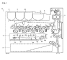
- the image forming apparatus 10 is a color printer including a plurality of image forming units 1-4, an intermediate transfer belt 5, an optical scanning device 6, a secondary transfer roller 7, a fixing device 8, a sheet discharge tray 9, a sheet feed cassette 21, and a conveyance path 22.
- the image forming apparatus 10 forms a monochrome image or a color image on a sheet based on input image data. It is noted that the sheet is a sheet-like material such as a sheet of paper, a sheet of coated paper, a postcard, an envelope, or an OHP sheet.
- other examples of the image forming apparatus of the present disclosure include a facsimile, a copier, and a multifunction peripheral.
- the image forming units 1-4 are electrophotographic image forming units each including a photoconductor drum 101, a charging device, a developing device, a primary transfer roller, and a cleaning device.
- the image forming units 1-4 are arranged in an alignment along the running direction (horizontal direction) of the intermediate transfer belt 5, and form an image forming portion of a so-called tandem method. Specifically, the image forming unit 1 forms a toner image corresponding to C (cyan), the image forming unit 2 forms a toner image corresponding to M (magenta), the image forming unit 3 forms a toner image corresponding to Y (yellow), and the image forming unit 4 forms a toner image corresponding to K (black).
- the intermediate transfer belt 5 is an intermediate transfer member on which the toner images of the respective colors are intermediately transferred from the photoconductor drums 101 of the image forming units 1-4.
- the optical scanning device 6 forms electrostatic latent images on the photoconductor drums 101 of the image forming units 1-4, by irradiating laser beams onto the photoconductor drums 101 based on the input image data of the respective colors.
- a color image is formed in the following procedure on a sheet supplied from the sheet feed cassette 21 along the conveyance path 22, and the sheet with the image formed thereon is discharged onto the sheet discharge tray 9.
- various types of conveyance rollers are provided in the conveyance path 22 in such a way as to convey a shee stacked on the sheet feed cassette 21 to the sheet discharge tray 9 via the secondary transfer roller 7 and the fixing device 8.
- the charging devices charge the surfaces of the photoconductor drums 101 uniformly to a certain potential.
- the optical scanning devices 6 irradiate the surfaces of the photoconductor drums 101 with laser beams based on the image data. With this operation, electrostatic latent images are formed on the surfaces of the photoconductor drums 101.
- the electrostatic latent images on the photoconductor drums 101 are developed (visualized) as toner images of respective colors by the developing devices. It is noted that toners (developers) are supplied from toner containers 11-14 of respective colors that are configured to be attachable/detachable.
- the toner images of respective colors formed on the photoconductor drums 101 of the image forming units 1-4 are transferred by the primary transfer rollers in sequence onto the intermediate transfer belt 5 so as to be overlaid thereon. With this operation, a color image is formed on the intermediate transfer belt 5 based on the image data.
- the color image on the intermediate transfer belt 5 is transferred by the secondary transfer roller 7 onto the sheet that has been conveyed from the sheet feed cassette 21 via the conveyance path 22.
- the color image transferred on the sheet is heated by the fixing device 8 so as to be fused and fixed onto the sheet. It is noted that the toner that has remained on the surfaces of the photoconductor drums 101 is removed by the cleaning devices.
- the image forming apparatus 10 includes a contact/separation mechanism (not shown) that causes the photoconductor drums 101 and the first transfer rollers of the image forming units 1-3 to contact and separate from the intermediate transfer belt 5.
- the contact/separation mechanism causes the photoconductor drums 101 and the first transfer rollers of the image forming units 1-3 to separate from the intermediate transfer belt 5. With this operation, only a black toner image is transferred from the image forming unit 4 to the intermediate transfer belt 5, and a monochrome image is transferred from the intermediate transfer belt 5 to the sheet.
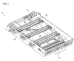
- the optical scanning device 6 includes a unit housing 60, a light source unit 61, a polygon mirror (an example of the scanning member) 62, outgoing mirrors 63-66, a scanning lens 67, and a reflection mirror 68.
- laser beams respectively corresponding to the image forming units 1-4 are emitted from the light source unit 61 and are deflected and scanned in a main scanning direction D1 by the polygon mirror 62.
- the laser beams scanned by the polygon mirror 62 are guided to the outgoing mirrors 63-66 via optical elements such as the scanning lens 67 and the reflection mirror 68.
- the laser beams reflected on the outgoing mirrors 63-66 are irradiated onto the photoconductor drums 101 of the image forming units 1-4.
- a direction perpendicular to the main scanning direction D1 on the surface of each photoconductor drum 101 and a direction perpendicular to the main scanning direction D1 on the surface of the polygon mirror 62 are both referred to as a sub scanning direction D2.
- a direction of the optical axis of the laser beam emitted from the light source unit 61 is referred to as an optical axis direction D3.
- the light source unit 61 includes LD boards 611-614, outgoing optical systems 615-618, a first reflection mirror 75, a second reflection mirror 76, third reflection mirrors 71-74, a cylindrical lens 77, and an aperture 78.
- the first reflection mirror 75, the second reflection mirror 76, the cylindrical lens 77, the aperture 78, and the polygon mirror 62 are used in common for scanning a plurality of laser beams emitted from the light source unit 61.
- the aperture 78 is omitted, and an attachment portion 601 to which the aperture 78 is attached is shown.
- the LD boards 611-614 are boards on which laser diodes 611A-614A are mounted as the light sources that emit laser beams that respectively correspond to the photoconductor drums 101.
- the laser diodes 611A-614A are disposed at different positions along the sub scanning direction D2.
- the laser diodes 611A-614A each may be a single-beam laser diode which emits a single laser beam, or may be a monolithic multi-beam laser diode which emits a plurality of laser beams. It is noted that when the laser diodes 611A-614A are monolithic multi-beam laser diodes, the optical scanning device 6 can write electrostatic latent images on the photoconductor drums 101 simultaneously by using a plurality of lines.
- the outgoing optical systems 615-618 emit, as parallel luminous fluxes, the laser beams emitted from the laser diodes 611A-614A respectively, and restrict the beam path widths of the laser beams.
- the third reflection mirrors 71-74 reflect, toward the first reflection mirror 75, laser beams emitted from the outgoing optical systems 615-618.
- the first reflection mirror 75 and the second reflection mirror 76 are disposed in the state where they are inclined by a predetermined angle around the sub scanning direction D2 as the rotation axis.
- the first reflection mirror 75 reflects the laser beams toward the second reflection mirror 76.
- the second reflection mirror 76 reflects the laser beams toward the polygon mirror 62. At this time, the laser beams reflected by the second reflection mirror 76 are incident on the cylindrical lens 77 via the aperture 78.
- the aperture 78 includes an opening portion 781 that restricts, to a width in a predetermined range, the width in the main scanning direction D1 of the laser beam that comes from the second reflection mirror 76 and is incident on the cylindrical lens 77.
- the aperture 78 is fixed to the unit housing 60 in the state where the aperture 78 is inserted in the attachment portion 601 formed in the unit housing 60 and the position of the aperture 78 in the first direction D1 has been adjusted.
- the unit housing 60 including the attachment portion 601 is an example of the first base portion.
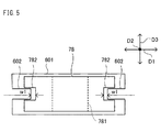
- FIG. 5 is a plan view showing the state where the aperture 78 is inserted in the attachment portion 601.
- the aperture 78 includes groove portions 782 that are formed along a longitudinal direction of the aperture 78.
- restriction portions 602 that are to be inserted in the groove portions 782 are provided.
- the restriction portions 602 of the attachment portion 601 are inserted in the groove portions 782, the movement of the aperture 78 in the optical axis direction D3 is restricted.
- a gap with a predetermined adjustment width w1 is formed in each of the left and right groove portions 782 of the aperture 78.
- the aperture 78 can move in the main scanning direction D1 in a predetermined range.
- the aperture 78 can move in the main scanning direction D1 in the attachment portion 601 within a width range that is twice as large as the adjustment width w1.
- the aperture 78 is an example of the second aperture
- the opening portion 781 is an example of the second opening portion.
- the cylindrical lens 77 is an example of a converging lens that forms a linear image on the reflection surface (deflection surface) of the polygon mirror 62 by converging the laser beams in the sub scanning direction D2.
- the laser beams are incident on the cylindrical lens 77 at positions that are different along the sub scanning direction D2 and incident on the polygon mirror 62 at different angles.
- the laser beams reflected on the polygon mirror 62 are guided to the outgoing mirrors 63-66 separately, and then guided to the photoconductor drums 101 of the image forming units 1-4.
- the laser diodes 611A-614A are provided at different positions along the sub scanning direction D2.
- the plurality of laser diodes 611A-614A may be disposed toward opposite directions in the sub scanning direction D2 when viewed from the polygon mirror 62.
- FIG. 6 is a schematic diagram showing the state where this configuration of the optical scanning device 6 is projected on a sub scanning plane that includes the sub scanning direction D2 and the optical axis direction D3 of the laser beams.
- a center position P1 of the laser diodes 611A-614A in the sub scanning direction D2 and a center position P2 of the polygon mirror 62 are on a same straight line.
- the arrangement of the LD boards 611-614, on which the laser diodes 611A-614A are installed may inhibit the miniaturization of the optical scanning device 6 in size in the sub scanning direction D2.
- the laser diodes 613A and 614A among the laser diodes 611A-614A are disposed below the center position P2 of the polygon mirror 62.
- the LD boards 613 and 614, on which the laser diodes 613A and 614A are installed may inhibit the miniaturization of the optical scanning device 6 in size in the sub scanning direction D2.
- the optical scanning device 6 is configured such that one polygon mirror 62 is used to scan the laser beams irradiated from the plurality of laser diodes 611A-614A, and this configuration is realized together with the miniaturization in size in the sub scanning direction D2. This is explained in the following.
- FIG. 7 is a schematic diagram showing the state where this configuration of the optical scanning device 6 is projected on a sub scanning plane that includes the sub scanning direction D2 and the optical axis direction D3 of the laser beams.
- the first reflection mirror 75 and the second reflection mirror 76 are disposed in the state where they are inclined by a predetermined angle around the main scanning direction D1 as the rotation axis. That is, the first reflection mirror 75 and the second reflection mirror 76 are disposed in the state where they are inclined by a predetermined angle around the main scanning direction D1 as a rotation axis, and inclined around the sub scanning direction D2 as another rotation axis.
- the first reflection mirror 75 and the second reflection mirror 76 reflect laser beams L1-L4 respectively irradiated from the laser diodes 611A-614A so as to travel parallel to the optical axis direction D3 of the laser beams L1-L4 toward positions that are different along the sub scanning direction D2. That is, the first reflection mirror 75 and the second reflection mirror 76 cause the laser beams L1-L4 to be moved in parallel along the sub scanning direction D2.
- the first reflection mirror 75 is inclined such that the laser beams L1-L4 are reflected downward in the sub scanning direction D2 and incident on the second reflection mirror 76.
- the second reflection mirror 76 is inclined such that the laser beams L1-L4 are reflected in a direction perpendicular to the sub scanning direction D2 and incident on the cylindrical lens 77.
- the arrangement positions of the laser diodes 611A-614A and the polygon mirror 62 in the sub scanning direction D2 can be arbitrarily shifted by changing the inclination angle of the first reflection mirror 75 and the second reflection mirror 76. That is, in the optical scanning device 6, it is possible to shift the center position P1 of the laser diodes 611A-614A and the center position P2 of the polygon mirror 62 in parallel along a direction. As a result, in the optical scanning device 6, it is possible to dispose the LD boards 611-614 with the laser diodes 611A-614A installed thereon by efficiently using the space in the sub scanning direction D2, thereby miniaturizing the optical scanning device 6 in size in the sub scanning direction D2.
- the laser beams do not rotate around the optical axis direction D3 as the rotation axis before and after they are reflected by the first reflection mirror 75 and the second reflection mirror 76.
- the laser beams rotate around the optical axis direction D3 as a rotation axis before and after they are reflected by the first reflection mirror 75 and the second reflection mirror 76.
- laser beams that are incident on the first reflection mirror 75 and laser beams that are reflected by the second reflection mirror 76 and incident on the cylindrical lens 77 are different from each other in attitude in the direction of rotation around the optical axis direction D3 as a rotation axis.
- FIG. 8A and FIG. 8B are diagrams showing reflection paths of the laser beams L4 when the first reflection mirror 75 and the second reflection mirror 76 are only inclined around the main scanning direction D1 as the rotation axis.
- FIG. 8A is a schematic diagram showing the state where the laser beams L4 reflected by the first reflection mirror 75 and the second reflection mirror 76 are projected on a main scanning plane that includes the main scanning direction D1 and the optical axis direction D3.
- FIG. 8B is a schematic diagram showing the state where the laser beams L4 reflected by the first reflection mirror 75 and the second reflection mirror 76 are projected on a sub scanning plane that includes the sub scanning direction D2 and the optical axis direction D3. It is noted that in FIG. 8A , the center beam of the laser beams L4 in the main scanning direction D1 is represented by L41, and end beams are represented by L42.
- the center beam L41 and the end beams L42 are different from each other in the beam path length between the first reflection mirror 75 and the second reflection mirror 76, but have the same whole beam path length before and after the reflection by the first reflection mirror 75 and the second reflection mirror 76.
- the laser beams L4 in the sub scanning plane are represented by a straight line because the positions of the laser beams L4 that are reflected by the first reflection mirror 75 and incident on the second reflection mirror 76 are the same in the sub scanning direction D2.
- FIG. 9A and FIG. 9B are diagrams showing reflection paths of the laser beams L4 when the first reflection mirror 75 and the second reflection mirror 76 are inclined around the main scanning direction D1 as a rotation axis, and are inclined around the sub scanning direction D2 as another rotation axis.
- FIG. 9A is a schematic diagram showing the state where the laser beams L4 reflected by the first reflection mirror 75 and the second reflection mirror 76 are projected on the main scanning plane.
- FIG. 9B is a schematic diagram showing the state where the laser beams L4 reflected by the first reflection mirror 75 and the second reflection mirror 76 are projected on the sub scanning plane. It is noted that in FIG. 11A and FIG. 11B, too, the center beam of the laser beams L4 in the main scanning direction D1 is represented by L41, and end beams are represented by L42.
- the center beam L41 and the end beams L42 are not only different from each other in the beam path length between the first reflection mirror 75 and the second reflection mirror 76, but also different from each other in the whole beam path length before and after the reflection by the first reflection mirror 75 and the second reflection mirror 76.
- FIG. 9A shows that when the first reflection mirror 75 and the second reflection mirror 76 are inclined around the main scanning direction D1 as a rotation axis, and are inclined around the sub scanning direction D2 as another rotation axis, the center beam L41 and the end beams L42 are not only different from each other in the beam path length between the first reflection mirror 75 and the second reflection mirror 76, but also different from each other in the whole beam path length before and after the reflection by the first reflection mirror 75 and the second reflection mirror 76.
- the center beam L41 and the end beams L42 of the laser beams L4 in the sub scanning plane are represented as light beams that are separated from each other in the sub scanning direction D2. That is, the laser beams L4 that are incident on the cylindrical lens 77 are in the state of having rotated around the optical axis direction D3 as the rotation axis with respect to the laser beams L4 that are incident on the first reflection mirror 75.
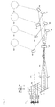
- FIG. 10 and FIG. 11 are diagrams showing the configuration of the outgoing optical system 618.
- FIG. 10 is a cross section taken along a line X-X and viewed from the direction indicated by the arrows X of FIG. 3 .
- FIG. 11 is a cross section taken along a line XI-XI and viewed from the direction indicated by the arrows XI of FIG. 10 .
- the outgoing optical system 618 is taken as an example and the description of the outgoing optical systems 615-617 that have the same configuration as the outgoing optical system 618 is omitted.
- the outgoing optical system 618 includes a base portion 681, a wall portion 682, a collimator lens 81, and an aperture 82.
- the base portion 681 and the wall portion 682 constitute a part of the unit housing 60.
- the wall portion 682 has a pass-through portion 683 in which the laser diode 614A mounted on the LD board 614 can be inserted.
- the collimator lens 81 is fixed to the base portion 681 by adhesion fixing using adhesive.
- the collimator lens 81 converts the laser beam emitted from the laser diode 614A of the LD board 614 to a parallel luminous flux and emits the parallel luminous flux.
- the aperture 82 is disposed between the collimator lens 81 and the third reflection mirrors 72-74, and in the outgoing optical system 615, the third reflection mirror 71 is disposed between the collimator lens 81 and the aperture 82.
- the base portion 681 includes a pass-through portion 684 that passes through between a front surface 681A and a rear surface 681B of the base portion 681, wherein the aperture 82 can be inserted in the pass-through portion 684.
- the pass-through portion 684 is set in the state of being inclined by a predetermined angle around the optical axis direction D3 with respect to the main scanning direction D1.
- the aperture 82 is fixed to the base portion 681 by adhesion fixing using adhesive.
- the base portion 681 is an example of the second base portion.
- the pass-through portion 684 includes restriction portions 685 that are projections respectively projecting from the opposite ends in the longitudinal direction toward the inside of the opening, wherein the restriction portions 685 are to be inserted in groove portions 84 of the aperture 82, and the groove portions 84 are described below.
- the aperture 82 includes an opening portion 83 and the groove portions 84.
- the opening portion 83 is used to restrict, to a width in a predetermined range, the beam path width of the laser beam which is traveling from the collimator lens 81 to the third reflection mirror 74.
- the width of the opening portion 83 of the aperture 82 in a longitudinal direction D4 is larger than the width of the opening portion 781 of the aperture 78 in the main scanning direction D1
- the width of the opening portion 83 of the aperture 82 in the short-length direction is smaller than the width of the opening portion 781 of the aperture 78 in the sub scanning direction D2.
- the aperture 82 is an example of the first aperture
- the opening portion 83 is an example of the first opening portion.
- the aperture 82 is disposed in the state where the longitudinal direction D4 of the opening portion 83 is inclined by a predetermined angle around the optical axis direction D3 with respect to the main scanning direction D1. Specifically, the aperture 82 is disposed in the state where the aperture 82 is inserted in the pass-through portion 684 of the base portion 681 such that the aperture 82 is inclined around the optical axis direction D3 as the rotation axis with respect to the main scanning direction D1.
- the inclination angle of the opening portion 83 has the same absolute value as the rotation angle of the laser beam around the optical axis direction D3 before and after the laser beam is incident on the first reflection mirror 75 and the second reflection mirror 76.
- the inclination direction D4 of the opening portion 83 is opposite to the rotation angle of the rotation of the laser beam around the optical axis direction D3 before and after the laser beam is incident on the first reflection mirror 75 and the second reflection mirror 76.
- inclination angles of the laser beam around the optical axis direction D3 before and after being incident on the first reflection mirror 75 and the second reflection mirror 76 can be calculated based on the inclination angles of the first reflection mirror 75 around the main scanning direction D1 and the sub scanning direction D2, and the inclination angles of the second reflection mirror 76 around the main scanning direction D1 and the sub scanning direction D2.
- the groove portions 84 are formed along the longitudinal direction of the aperture 82, and the restriction portions 685 of the pass-through portion 684 are inserted in the groove portions 84. This restricts the aperture 82 from moving in the optical axis direction D3 and the longitudinal direction D4 of the opening portion 83. On the other hand, the aperture 82 is allowed to move in an insertion direction D5 that is perpendicular to the longitudinal direction D4 and the optical axis direction D3, by the groove portions 84 and the pass-through portion 684.
- the aperture 82 is fixed to the base portion 681 by adhesion fixing using adhesive.
- adhesive for example, a photocurable resin that is cured by ultraviolet irradiation is used as the adhesive. In that case, it is necessary to irradiate ultraviolet light on the photocurable resin after the photocurable resin is applied to the aperture 82 and the pass-through portion 684.
- the aperture 82 could be held only by an upper end portion 82B of the aperture 82, the chuck portion of the robot arm or the hand of the worker that would be holding the aperture 82 would interrupt with the application of the photocurable resin and the irradiation of the ultraviolet light on the photocurable resin.
- a lower end portion 82A of the aperture 82 projects from the rear surface 681B of the base portion 681 in the state where the aperture 82 is inserted in the pass-through portion 684 to such a position where the laser beam is incident on the opening portion 83.
- the photocurable resin may be applied to the aperture 82 and the pass-through portion 684 from the rear surface 681B side of the base portion 681 and the ultraviolet light may be irradiated on the photocurable resin from the rear surface 681B side of the base portion 681 in the state where the upper end portion 82B of the aperture 82 is held.
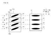
- FIG. 12 is a schematic diagram viewing, in the optical axis direction D3, the laser beams L1-L4 that are emitted from the laser diodes 611A-614A and incident on the third reflection mirrors 71-74 and the cylindrical lens 77 in the optical scanning device 6.
- the laser beams L1-L4 that are incident on the third reflection mirrors 71-74 enter the state where they are inclined around the optical axis direction D3 as the rotation axis with respect to the main scanning direction D1 since the beam path width of the laser beams L1-L4 is restricted by the opening portion 83 of the aperture 82.
- the laser beams L1-L4 that have been reflected by the third reflection mirrors 71-74 are reflected by the first reflection mirror 75 and the second reflection mirror 76, and then incident on the cylindrical lens 77.
- the laser beams L1-L4 that are incident on the first reflection mirror 75 are rotated in a direction opposite to the inclination direction of the laser beams L1-L4 in the third reflection mirrors 71-74 around the optical axis direction D3 as the rotation axis before and after the reflection by the first reflection mirror 75 and the second reflection mirror 76.
- the optical scanning device 6 as shown in FIG. 12 , it is possible to make the longitudinal direction of the laser beams L1-L4 that are incident on the cylindrical lens 77, to be parallel to the main scanning direction D1 with use of the first reflection mirror 75 and the second reflection mirror 76.
- the optical scanning device 6 in the configuration where the laser beams L1-L4 can be moved in parallel along the sub scanning direction D2 by using the first reflection mirror 75 and the second reflection mirror 76, it is possible to restrict the inclination of the laser beams L1-L4 that are incident on the cylindrical lens 77. It is noted that when the laser beams L1-L4 that are incident on the cylindrical lens 77 are not inclined due to the inclination angle of the first reflection mirror 75 and the second reflection mirror 76, a configuration where the opening portion 83 of the aperture 82 is not inclined may be considered as another embodiment.
- the third reflection mirrors 71-74 are disposed in the state where upper end surfaces 71A-74A thereof are inclined with respect to the main scanning direction D1.
- the third reflection mirrors 71-74 are rectangular and fixed in the attitude where the upper end surfaces 71A-74A of the third reflection mirrors 71-74 are inclined with respect to the main scanning direction D1 by the same angle as the inclination angle of the longitudinal direction of the laser beams L1-L4. This makes it possible to shorten the arrangement interval of the laser diodes 611A-614A in the sub scanning direction D2, thereby reducing the size of the optical scanning device 6 in the sub scanning direction D2.
- the third reflection mirrors 71-74 may be formed in a shape that enables them to be inclined around the optical axis direction D3 of the laser beam as the rotation axis, by the same angle as the longitudinal direction D4 of the opening portion 83.
- FIG. 13 shows a configuration example where the third reflection mirrors 71-74 are fixed in the attitude where the upper end surfaces 71A-74A are parallel to the main scanning direction D1.
- a relatively large width needs to be secured for the laser beams L1-L4 to be inclined.
- miniaturizing the optical scanning device 6 in size in the sub scanning direction D2 is inhibited.
- the aperture 78 is disposed between the second reflection mirror 76 and the cylindrical lens 77 along the irradiation direction of the laser beams, it is possible to restrict the width of the laser beams in the main scanning direction D1 in the state where the longitudinal direction of the laser beams is parallel to the main scanning direction D1.
- the attachment portion 601 has a shape that allows the aperture 78 to move only in the main scanning direction D1.
- a configuration for restricting the width of the laser beams in the main scanning direction D1 is realized with a simpler structure than a case where the pass-through portion 684 is configured such that the aperture 82 can move in the longitudinal direction D4 of the opening portion 83.
- the aperture 78 is disposed on the downstream side of the second reflection mirror 76 and on the upstream side of the polygon mirror 62 in the laser beam irradiation direction.
- the aperture 78 may be disposed between the cylindrical lens 77 and the polygon mirror 62.
- the optical scanning device 6 may not include the aperture 78, and the pass-through portion 684 may allow the aperture 82 to move in a predetermined adjustment range in a direction parallel to the longitudinal direction D4 of the opening portion 83.
- the pass-through portion 684 may have the same configuration as the attachment portion 601 and the aperture 78 so as to allow the aperture 82 to move in a direction parallel to the longitudinal direction D4 of the opening portion 83. In this case, too, it is possible to restrict, to a predetermined range, the width in the main scanning direction D1 of the laser beam that is incident on the cylindrical lens 77.
- the adjustment of the fixed state of the aperture 82 may be performed while photographing the laser beam by a camera including an imaging element such as CCD.
- the camera may be disposed between the cylindrical lens 77 and the polygon mirror 62, and after the adjustment work, the camera may be removed.
- the beam width in the main scanning direction D1 increases after the laser beam passes through the aperture 82.
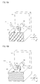
- the size of the camera is small relative to the beam width in the main scanning direction D1 of the laser beam, the end portions of the laser beam in the main scanning direction D1 may not be included in a photographed image P10 taken by the camera, as shown in FIG. 14A .
- the camera is disposed in the optical scanning device 6 such that the left-right direction of the photographed image P10 is parallel to the main scanning direction D1 and the up-down direction is parallel to the sub scanning direction D2.
- the laser beam is represented by the hatched area.
- the setting position of the camera in the optical scanning device 6 is restricted when the fixed state of the aperture 82 is adjusted.
- the image forming apparatus 10 provides a configuration where a small-size camera can be used when the fixed state of the aperture 82 is adjusted. It is noted that the components that are the same as those of the image forming apparatus 10 and the optical scanning device 6 described in the first embodiment are assigned the same reference signs, and description thereof is omitted.
- the aperture 82 includes a cut portion 97 which is formed along the insertion direction D5 that is perpendicular to the longitudinal direction D4 of the opening portion 83, and in which a blocking member 98 that is described below can be inserted.
- the cut portion 97 is an example of the first cut portion
- the blocking member 98 is an example of the first blocking member.
- the cut portion 97 is formed at a predetermined position such that the center thereof in the longitudinal direction D4 matches the center of the opening portion 83 in the longitudinal direction D4.
- the cut portion 97 is an indent portion formed on the surface (namely, the front surface) of the aperture 82 on the downstream side in the emission direction of the laser beam, and does not pass through the aperture 82 in a direction along the optical axis of the laser beam. As a result, the cut portion 97 does not affect the performance of the opening portion 83 of the aperture 82 in restricting the width of the laser beam.
- the blocking member 98 which is in the shape of a long cylinder and configured to block a part of the laser beam emitted from the laser diode 614A, can be attached to and detached from the cut portion 97.
- a photograph is taken by the camera in the state where the blocking member 98 is attached to the cut portion 97, in the photographed image P10, a part of the laser beam emitted from the laser diode 614A is blocked by the blocking member 98, as shown in FIG. 14B .
- a blocked area A1 that is formed in the laser beam by the blocking member 98 has a predetermined relationship with the opening portion 83 of the aperture 82.
- the center of the opening portion 83 in the longitudinal direction D4 matches the center of the blocked area A1 in the same direction. It is noted that a border line between the blocked area A1 and the laser beam forms a line segment that is perpendicular to the longitudinal direction D4 of the opening portion 83.
- the center position of the laser beam is the center of a width w2 that passes through the centers of the border lines of the blocked area A1 and the laser beam, and is perpendicular to the border lines.
- the blocked area A1 generated by the blocking member 98 is inclined as shown in FIG. 14C when the laser beam irradiated from the aperture 82 enters the camera in an inclined state.
- the blocked area A1 it is possible, by referring to the blocked area A1, to identify the inclination of the laser beam.
- the optical scanning device 6 it is possible to easily adjust the fixed state of the aperture 82 in the pass-through portion 684.
- the following work process is executed in the work process executed as the fixing method of the aperture 82.
- the blocking member 98 is inserted in the cut portion 97 of the aperture 82.
- the laser beam that has passed through the opening portion 83 is photographed by the camera installed at a predetermined position (Step 1).
- the inclination and the center position in the longitudinal direction D4 of the laser beam that has passed through the opening portion 83 are identified based on the photographed image taken by the camera (Step 2).
- the fixed state of the aperture 82 is adjusted based on the identified inclination and center position of the laser beam (Step 3).
- the optical scanning device 6 of the second embodiment it is possible to use a small-size camera when the fixed state of the aperture 82 is adjusted, resulting in relaxation of the restriction made to the setting position of the camera in the optical scanning device 6.
- the camera may be disposed between the reflection mirrors 71-74 and the reflection mirror 75. In that case, the laser beam photographed by the camera is inclined. However, by taking the inlination into account, it is possible to adjust the fixed state of the aperture 82 appropriately.
- the aperture 82 includes, in addition to the cut portion 97, a cut portion 914 which is formed in a direction parallel to the longitudinal direction D4 of the opening portion 83, and in which a blocking member 915 that is described below can be inserted.
- the cut portion 914 is an example of the second cut portion
- the blocking member 915 is an example of the second blocking member
- the cut portion 914 is formed at a predetermined position such that the center thereof in the insertion direction D5 matches the center of the opening portion 83 in the insertion direction D5, wherein the insertion direction D5 is perpendicular to the longitudinal direction D4 of the opening portion 83.
- the cut portion 914 is an indent portion formed on the surface (namely, the front surface) of the aperture 82 on the downstream side in the emission direction of the laser beam, and does not pass through the aperture 82 in a direction along the optical axis of the laser beam. As a result, the cut portion 914 does not affect the performance of the opening portion 83 of the aperture 82 in restricting the width of the laser beam.
- the blocking member 915 which is in the shape of a long cylinder and configured to block a part of the laser beam emitted from the laser diode 614A, can be attached to and detached from the cut portion 914.
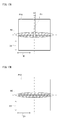
- a photograph is taken by the camera in the state where the blocking member 915 is attached to the cut portion 914, in the photographed image P10, a part of the laser beam is blocked by the blocking member 915, as shown in FIG. 17A .
- a blocked area B2 that is formed in the laser beam by the blocking member 915 has a predetermined relationship with the opening portion 83 of the aperture 82.
- the longitudinal direction D4 of the opening portion 83 is parallel to the longitudinal direction of the blocked area B2, and a border line between the blocked area B2 and the laser beam forms a line segment that is parallel to the longitudinal direction D4 of the opening portion 83.
- the following work process is executed in the work process executed as the fixing method of the aperture 82.
- the blocking member 98 is inserted in the cut portion 97 of the aperture 82, and the blocking member 915 is inserted in the cut portion 914 of the aperture 82.
- the laser beam that has passed through the opening portion 83 is photographed by the camera installed at a predetermined position (Step 1).
- the inclination and the center position in the longitudinal direction D4 of the laser beam that has passed through the opening portion 83 are identified based on the photographed image taken by the camera (Step 2).
- the fixed state of the aperture 82 is adjusted based on the identified inclination and center position of the laser beam (Step 3).
- the image forming apparatus 10 of the third embodiment it is possible to use a small-size camera when the fixed state of the aperture 82 is adjusted, resulting in relaxation of the restriction made to the setting position of the camera in the optical scanning device 6.
- the cut portion 97 may be omitted and only the cut portion 914 may be included. In that case, it is possible to identify the inclination of the laser beam by referring to the blocked area B2 in the photographed image P10 as shown in FIG. 17B .
Landscapes
- Physics & Mathematics (AREA)
- Optics & Photonics (AREA)
- General Physics & Mathematics (AREA)
- Engineering & Computer Science (AREA)
- Multimedia (AREA)
- Signal Processing (AREA)
- Facsimile Scanning Arrangements (AREA)
- Mechanical Optical Scanning Systems (AREA)
- Exposure Or Original Feeding In Electrophotography (AREA)
- Laser Beam Printer (AREA)
Abstract
Description
- The present disclosure relates to an optical scanning device for scanning a laser beam, an image forming apparatus including the optical scanning device, and an aperture fixing method.
- An electrophotographic image forming apparatus includes an optical scanning device that forms an electrostatic latent image on a photoconductor by scanning a laser beam over the surface of the photoconductor. The optical scanning device includes a light source and a polygon mirror, wherein the light source emits a laser beam, and the polygon mirror scans the laser beam emitted from the light source. In addition, there is known a configuration where one polygon mirror is used to scan laser beams irradiated from a plurality of light sources. Specifically, the plurality of light sources are disposed at different positions along a sub scanning direction that is perpendicular to an optical axis direction of the laser beams and a main scanning direction in which the laser beams are scanned. In this configuration, laser beams from the light sources are incident on the polygon mirror at different angles, and are reflected and guided thereby to corresponding photoconductor drums.
- An optical scanning device according to an aspect of the present disclosure includes a scanning member, a plurality of light sources, a first reflection mirror, and a second reflection mirror. The scanning member scans incident laser beams in a predetermined main scanning direction. The plurality of light sources emit the laser beams respectively from positions that are different along a sub scanning direction that is perpendicular to an optical axis direction of the laser beams and the main scanning direction. The first reflection mirror is inclined around the main scanning direction as a rotation axis, is inclined around the sub scanning direction as another rotation axis, and reflects the laser beams emitted from the light sources. The second reflection mirror is inclined around the main scanning direction as a rotation axis, is inclined around the sub scanning direction as another rotation axis, and reflects the laser beams reflected by the first reflection mirror toward the scanning member.
- An image forming apparatus according to another aspect of the present disclosure includes the optical scanning device.
- An aperture fixing method according to a further aspect of the present disclosure includes: photographing, at a predetermined position, a laser beam that has passed through the opening portion in a state where the first blocking member is inserted in the first cut portion of the aperture; identifying a center position in the longitudinal direction of the opening portion, of the laser beam that has passed through the opening portion, based on a photographed image of the laser beam; and adjusting a fixed state of the aperture based on an identified center position of the laser beam in the longitudinal direction of the opening portion.
- This Summary is provided to introduce a selection of concepts in a simplified form that are further described below in the Detailed Description with reference where appropriate to the accompanying drawings. This Summary is not intended to identify key features or essential features of the claimed subject matter, nor is it intended to be used to limit the scope of the claimed subject matter. Furthermore, the claimed subject matter is not limited to implementations that solve any or all disadvantages noted in any part of this disclosure.
-
-
FIG. 1 is a diagram showing the configuration of an image forming apparatus according to the first embodiment of the present disclosure. -
FIG. 2 is a diagram showing the configuration of an optical scanning device according to the first embodiment of the present disclosure. -
FIG. 3 is a diagram showing the configuration of a light source unit of the optical scanning device according to the first embodiment of the present disclosure. -
FIG. 4 is a diagram showing the configuration of the light source unit of the optical scanning device according to the first embodiment of the present disclosure. -
FIG. 5 is a plan view of a second aperture of the optical scanning device according to the first embodiment of the present disclosure. -
FIG. 6 is a schematic diagram showing beam paths of an optical scanning device according to a comparative example. -
FIG. 7 is a schematic diagram showing beam paths of the optical scanning device according to the first embodiment of the present disclosure. -
FIG. 8A and FIG. 8B are schematic diagrams showing beam paths of an optical scanning device according to a comparative example. -
FIG. 9A and FIG. 9B are schematic diagrams showing beam paths of the optical scanning device according to the first embodiment of the present disclosure. -
FIG. 10 is a diagram showing the configuration of an outgoing optical system of the optical scanning device according to the first embodiment of the present disclosure. -
FIG. 11 is a diagram showing the configuration of the outgoing optical system of the optical scanning device according to the first embodiment of the present disclosure. -
FIG. 12 is a diagram showing laser beams incident on third reflection mirrors and cylindrical lens in the optical scanning device according to the first embodiment of the present disclosure. -
FIG. 13 is a diagram showing laser beams incident on third reflection mirrors and cylindrical lens in an optical scanning device according to a comparative example. -
FIGS. 14A-14C are diagrams showing examples of photographed images taken by a camera used for an aperture fixing method in an optical scanning device according to a second embodiment of the present disclosure. -
FIG. 15A and FIG. 15B are diagrams showing other examples of an outgoing optical system of the optical scanning device according to the second embodiment of the present disclosure. -
FIG. 16A and FIG. 16B are diagrams showing other examples of an outgoing optical system of the optical scanning device according to a third embodiment of the present disclosure. -
FIGS. 17A-17C are diagrams showing examples of photographed images taken by a camera used for an aperture fixing method in an optical scanning device according to a third embodiment of the present disclosure. - The following describes embodiments of the present disclusure with reference to the drawings, for the understanding of the disclosure. It is noted that embodiments described in the following are merely concrete examples of the present disclosure, and should not limit the technical scope of the present disclosure.
- First, an outlined configuration of an
image forming apparatus 10 in an embodiment of the present disclosure is described. - As shown in
FIG. 1 , theimage forming apparatus 10 is a color printer including a plurality of image forming units 1-4, anintermediate transfer belt 5, anoptical scanning device 6, a secondary transfer roller 7, afixing device 8, a sheet discharge tray 9, asheet feed cassette 21, and aconveyance path 22. Theimage forming apparatus 10 forms a monochrome image or a color image on a sheet based on input image data. It is noted that the sheet is a sheet-like material such as a sheet of paper, a sheet of coated paper, a postcard, an envelope, or an OHP sheet. In addition, other examples of the image forming apparatus of the present disclosure include a facsimile, a copier, and a multifunction peripheral. - The image forming units 1-4 are electrophotographic image forming units each including a
photoconductor drum 101, a charging device, a developing device, a primary transfer roller, and a cleaning device. The image forming units 1-4 are arranged in an alignment along the running direction (horizontal direction) of theintermediate transfer belt 5, and form an image forming portion of a so-called tandem method. Specifically, theimage forming unit 1 forms a toner image corresponding to C (cyan), theimage forming unit 2 forms a toner image corresponding to M (magenta), theimage forming unit 3 forms a toner image corresponding to Y (yellow), and theimage forming unit 4 forms a toner image corresponding to K (black). - The
intermediate transfer belt 5 is an intermediate transfer member on which the toner images of the respective colors are intermediately transferred from thephotoconductor drums 101 of the image forming units 1-4. Theoptical scanning device 6 forms electrostatic latent images on thephotoconductor drums 101 of the image forming units 1-4, by irradiating laser beams onto thephotoconductor drums 101 based on the input image data of the respective colors. - In the
image forming apparatus 10 configured as such, a color image is formed in the following procedure on a sheet supplied from thesheet feed cassette 21 along theconveyance path 22, and the sheet with the image formed thereon is discharged onto the sheet discharge tray 9. It is noted that various types of conveyance rollers are provided in theconveyance path 22 in such a way as to convey a shee stacked on thesheet feed cassette 21 to the sheet discharge tray 9 via the secondary transfer roller 7 and thefixing device 8. - First, in the image forming units 1-4, the charging devices charge the surfaces of the
photoconductor drums 101 uniformly to a certain potential. Next, theoptical scanning devices 6 irradiate the surfaces of thephotoconductor drums 101 with laser beams based on the image data. With this operation, electrostatic latent images are formed on the surfaces of thephotoconductor drums 101. The electrostatic latent images on the photoconductor drums 101 are developed (visualized) as toner images of respective colors by the developing devices. It is noted that toners (developers) are supplied from toner containers 11-14 of respective colors that are configured to be attachable/detachable. - Subsequently, the toner images of respective colors formed on the photoconductor drums 101 of the image forming units 1-4 are transferred by the primary transfer rollers in sequence onto the
intermediate transfer belt 5 so as to be overlaid thereon. With this operation, a color image is formed on theintermediate transfer belt 5 based on the image data. Next, the color image on theintermediate transfer belt 5 is transferred by the secondary transfer roller 7 onto the sheet that has been conveyed from thesheet feed cassette 21 via theconveyance path 22. Subsequently, the color image transferred on the sheet is heated by the fixingdevice 8 so as to be fused and fixed onto the sheet. It is noted that the toner that has remained on the surfaces of the photoconductor drums 101 is removed by the cleaning devices. - In addition, the
image forming apparatus 10 includes a contact/separation mechanism (not shown) that causes the photoconductor drums 101 and the first transfer rollers of the image forming units 1-3 to contact and separate from theintermediate transfer belt 5. When a monochrome image is printed in theimage forming apparatus 10, the contact/separation mechanism causes the photoconductor drums 101 and the first transfer rollers of the image forming units 1-3 to separate from theintermediate transfer belt 5. With this operation, only a black toner image is transferred from theimage forming unit 4 to theintermediate transfer belt 5, and a monochrome image is transferred from theintermediate transfer belt 5 to the sheet. - Next, details of the
optical scanning device 6 are described. - As shown in
FIG. 1 andFIG. 2 , theoptical scanning device 6 includes aunit housing 60, alight source unit 61, a polygon mirror (an example of the scanning member) 62, outgoing mirrors 63-66, ascanning lens 67, and areflection mirror 68. In theoptical scanning device 6, laser beams respectively corresponding to the image forming units 1-4 are emitted from thelight source unit 61 and are deflected and scanned in a main scanning direction D1 by thepolygon mirror 62. The laser beams scanned by thepolygon mirror 62 are guided to the outgoing mirrors 63-66 via optical elements such as thescanning lens 67 and thereflection mirror 68. Subsequently, the laser beams reflected on the outgoing mirrors 63-66 are irradiated onto the photoconductor drums 101 of the image forming units 1-4. It is noted that a direction perpendicular to the main scanning direction D1 on the surface of eachphotoconductor drum 101 and a direction perpendicular to the main scanning direction D1 on the surface of thepolygon mirror 62 are both referred to as a sub scanning direction D2. In addition, a direction of the optical axis of the laser beam emitted from thelight source unit 61 is referred to as an optical axis direction D3. - As shown in
FIG. 3 andFIG. 4 , thelight source unit 61 includes LD boards 611-614, outgoing optical systems 615-618, afirst reflection mirror 75, asecond reflection mirror 76, third reflection mirrors 71-74, acylindrical lens 77, and anaperture 78. In theoptical scanning device 6, thefirst reflection mirror 75, thesecond reflection mirror 76, thecylindrical lens 77, theaperture 78, and thepolygon mirror 62 are used in common for scanning a plurality of laser beams emitted from thelight source unit 61. It is noted that inFIG. 4 , theaperture 78 is omitted, and anattachment portion 601 to which theaperture 78 is attached is shown. - The LD boards 611-614 are boards on which
laser diodes 611A-614A are mounted as the light sources that emit laser beams that respectively correspond to the photoconductor drums 101. Here, thelaser diodes 611A-614A are disposed at different positions along the sub scanning direction D2. Thelaser diodes 611A-614A each may be a single-beam laser diode which emits a single laser beam, or may be a monolithic multi-beam laser diode which emits a plurality of laser beams. It is noted that when thelaser diodes 611A-614A are monolithic multi-beam laser diodes, theoptical scanning device 6 can write electrostatic latent images on the photoconductor drums 101 simultaneously by using a plurality of lines. - The outgoing optical systems 615-618 emit, as parallel luminous fluxes, the laser beams emitted from the
laser diodes 611A-614A respectively, and restrict the beam path widths of the laser beams. - The third reflection mirrors 71-74 reflect, toward the
first reflection mirror 75, laser beams emitted from the outgoing optical systems 615-618. In addition, thefirst reflection mirror 75 and thesecond reflection mirror 76 are disposed in the state where they are inclined by a predetermined angle around the sub scanning direction D2 as the rotation axis. With this configuration, thefirst reflection mirror 75 reflects the laser beams toward thesecond reflection mirror 76. In addition, thesecond reflection mirror 76 reflects the laser beams toward thepolygon mirror 62. At this time, the laser beams reflected by thesecond reflection mirror 76 are incident on thecylindrical lens 77 via theaperture 78. - The
aperture 78 includes anopening portion 781 that restricts, to a width in a predetermined range, the width in the main scanning direction D1 of the laser beam that comes from thesecond reflection mirror 76 and is incident on thecylindrical lens 77. Theaperture 78 is fixed to theunit housing 60 in the state where theaperture 78 is inserted in theattachment portion 601 formed in theunit housing 60 and the position of theaperture 78 in the first direction D1 has been adjusted. Here, theunit housing 60 including theattachment portion 601 is an example of the first base portion. -
FIG. 5 is a plan view showing the state where theaperture 78 is inserted in theattachment portion 601. As shown inFIG. 5 , theaperture 78 includesgroove portions 782 that are formed along a longitudinal direction of theaperture 78. On the other hand, in theattachment portion 601,restriction portions 602 that are to be inserted in thegroove portions 782 are provided. When therestriction portions 602 of theattachment portion 601 are inserted in thegroove portions 782, the movement of theaperture 78 in the optical axis direction D3 is restricted. - On the other hand, in the state where the
aperture 78 is inserted in theattachment portion 601, a gap with a predetermined adjustment width w1 is formed in each of the left andright groove portions 782 of theaperture 78. With this configuration, in theattachment portion 601, theaperture 78 can move in the main scanning direction D1 in a predetermined range. Specifically, theaperture 78 can move in the main scanning direction D1 in theattachment portion 601 within a width range that is twice as large as the adjustment width w1. With this configuration, when theoptical scanning device 6 is assembled, it is possible to adjust the incident position of the laser beam in the main scanning direction D1 on thepolygon mirror 62 by adjusting the position of theaperture 78 in the main scanning direction D1. It is noted that theaperture 78 is an example of the second aperture, and theopening portion 781 is an example of the second opening portion. - The
cylindrical lens 77 is an example of a converging lens that forms a linear image on the reflection surface (deflection surface) of thepolygon mirror 62 by converging the laser beams in the sub scanning direction D2. Here, the laser beams are incident on thecylindrical lens 77 at positions that are different along the sub scanning direction D2 and incident on thepolygon mirror 62 at different angles. With this configuration, the laser beams reflected on thepolygon mirror 62 are guided to the outgoing mirrors 63-66 separately, and then guided to the photoconductor drums 101 of the image forming units 1-4. - Meanwhile, as described above, the
laser diodes 611A-614A are provided at different positions along the sub scanning direction D2. Here, in theoptical scanning device 6, the plurality oflaser diodes 611A-614A may be disposed toward opposite directions in the sub scanning direction D2 when viewed from thepolygon mirror 62. Here,FIG. 6 is a schematic diagram showing the state where this configuration of theoptical scanning device 6 is projected on a sub scanning plane that includes the sub scanning direction D2 and the optical axis direction D3 of the laser beams. As shown inFIG. 6 , in this case, a center position P1 of thelaser diodes 611A-614A in the sub scanning direction D2 and a center position P2 of thepolygon mirror 62 are on a same straight line. - However, according to the configuration shown in
FIG. 6 , the arrangement of the LD boards 611-614, on which thelaser diodes 611A-614A are installed, may inhibit the miniaturization of theoptical scanning device 6 in size in the sub scanning direction D2. Specifically, inFIG. 6 , thelaser diodes laser diodes 611A-614A are disposed below the center position P2 of thepolygon mirror 62. As a result, theLD boards laser diodes optical scanning device 6 in size in the sub scanning direction D2. - On the other hand, the
optical scanning device 6 is configured such that onepolygon mirror 62 is used to scan the laser beams irradiated from the plurality oflaser diodes 611A-614A, and this configuration is realized together with the miniaturization in size in the sub scanning direction D2. This is explained in the following. Here,FIG. 7 is a schematic diagram showing the state where this configuration of theoptical scanning device 6 is projected on a sub scanning plane that includes the sub scanning direction D2 and the optical axis direction D3 of the laser beams. - As shown in
FIG. 7 , in thelight source unit 61, thefirst reflection mirror 75 and thesecond reflection mirror 76 are disposed in the state where they are inclined by a predetermined angle around the main scanning direction D1 as the rotation axis. That is, thefirst reflection mirror 75 and thesecond reflection mirror 76 are disposed in the state where they are inclined by a predetermined angle around the main scanning direction D1 as a rotation axis, and inclined around the sub scanning direction D2 as another rotation axis. - In particular, the
first reflection mirror 75 and thesecond reflection mirror 76 reflect laser beams L1-L4 respectively irradiated from thelaser diodes 611A-614A so as to travel parallel to the optical axis direction D3 of the laser beams L1-L4 toward positions that are different along the sub scanning direction D2. That is, thefirst reflection mirror 75 and thesecond reflection mirror 76 cause the laser beams L1-L4 to be moved in parallel along the sub scanning direction D2. Specifically, as shown inFIG. 7 , thefirst reflection mirror 75 is inclined such that the laser beams L1-L4 are reflected downward in the sub scanning direction D2 and incident on thesecond reflection mirror 76. In addition, thesecond reflection mirror 76 is inclined such that the laser beams L1-L4 are reflected in a direction perpendicular to the sub scanning direction D2 and incident on thecylindrical lens 77. - In the
optical scanning device 6 configured as described above, the arrangement positions of thelaser diodes 611A-614A and thepolygon mirror 62 in the sub scanning direction D2 can be arbitrarily shifted by changing the inclination angle of thefirst reflection mirror 75 and thesecond reflection mirror 76. That is, in theoptical scanning device 6, it is possible to shift the center position P1 of thelaser diodes 611A-614A and the center position P2 of thepolygon mirror 62 in parallel along a direction. As a result, in theoptical scanning device 6, it is possible to dispose the LD boards 611-614 with thelaser diodes 611A-614A installed thereon by efficiently using the space in the sub scanning direction D2, thereby miniaturizing theoptical scanning device 6 in size in the sub scanning direction D2. - Meanwhile, when the
first reflection mirror 75 and thesecond reflection mirror 76 are only inclined around the sub scanning direction D2 as the rotation axis, the laser beams do not rotate around the optical axis direction D3 as the rotation axis before and after they are reflected by thefirst reflection mirror 75 and thesecond reflection mirror 76. However, with the configuration of theoptical scanning device 6 where thefirst reflection mirror 75 and thesecond reflection mirror 76 are disposed in the state where they are inclined by a predetermined angle around the main scanning direction D1 as a rotation axis, and inclined around the sub scanning direction D2 as another rotation axis, the laser beams rotate around the optical axis direction D3 as a rotation axis before and after they are reflected by thefirst reflection mirror 75 and thesecond reflection mirror 76. As a result, laser beams that are incident on thefirst reflection mirror 75 and laser beams that are reflected by thesecond reflection mirror 76 and incident on thecylindrical lens 77 are different from each other in attitude in the direction of rotation around the optical axis direction D3 as a rotation axis. - Here,
FIG. 8A and FIG. 8B are diagrams showing reflection paths of the laser beams L4 when thefirst reflection mirror 75 and thesecond reflection mirror 76 are only inclined around the main scanning direction D1 as the rotation axis. In addition,FIG. 8A is a schematic diagram showing the state where the laser beams L4 reflected by thefirst reflection mirror 75 and thesecond reflection mirror 76 are projected on a main scanning plane that includes the main scanning direction D1 and the optical axis direction D3. On the other hand,FIG. 8B is a schematic diagram showing the state where the laser beams L4 reflected by thefirst reflection mirror 75 and thesecond reflection mirror 76 are projected on a sub scanning plane that includes the sub scanning direction D2 and the optical axis direction D3. It is noted that inFIG. 8A , the center beam of the laser beams L4 in the main scanning direction D1 is represented by L41, and end beams are represented by L42. - As shown in
FIG. 8A , when thefirst reflection mirror 75 and thesecond reflection mirror 76 are only inclined around the main scanning direction D1 as the rotation axis, the center beam L41 and the end beams L42 are different from each other in the beam path length between thefirst reflection mirror 75 and thesecond reflection mirror 76, but have the same whole beam path length before and after the reflection by thefirst reflection mirror 75 and thesecond reflection mirror 76. In addition, as shown inFIG. 8B , the laser beams L4 in the sub scanning plane are represented by a straight line because the positions of the laser beams L4 that are reflected by thefirst reflection mirror 75 and incident on thesecond reflection mirror 76 are the same in the sub scanning direction D2. - On the other hand,
FIG. 9A and FIG. 9B are diagrams showing reflection paths of the laser beams L4 when thefirst reflection mirror 75 and thesecond reflection mirror 76 are inclined around the main scanning direction D1 as a rotation axis, and are inclined around the sub scanning direction D2 as another rotation axis. In addition,FIG. 9A is a schematic diagram showing the state where the laser beams L4 reflected by thefirst reflection mirror 75 and thesecond reflection mirror 76 are projected on the main scanning plane. On the other hand,FIG. 9B is a schematic diagram showing the state where the laser beams L4 reflected by thefirst reflection mirror 75 and thesecond reflection mirror 76 are projected on the sub scanning plane. It is noted that in FIG. 11A and FIG. 11B, too, the center beam of the laser beams L4 in the main scanning direction D1 is represented by L41, and end beams are represented by L42. - As shown in
FIG. 9A , when thefirst reflection mirror 75 and thesecond reflection mirror 76 are inclined around the main scanning direction D1 as a rotation axis, and are inclined around the sub scanning direction D2 as another rotation axis, the center beam L41 and the end beams L42 are not only different from each other in the beam path length between thefirst reflection mirror 75 and thesecond reflection mirror 76, but also different from each other in the whole beam path length before and after the reflection by thefirst reflection mirror 75 and thesecond reflection mirror 76. In addition, as shown inFIG. 9B , since the positions of the laser beams L4 that are reflected by thefirst reflection mirror 75 and incident on thesecond reflection mirror 76 vary in the sub scanning direction D2 and the optical axis direction D3, the center beam L41 and the end beams L42 of the laser beams L4 in the sub scanning plane are represented as light beams that are separated from each other in the sub scanning direction D2. That is, the laser beams L4 that are incident on thecylindrical lens 77 are in the state of having rotated around the optical axis direction D3 as the rotation axis with respect to the laser beams L4 that are incident on thefirst reflection mirror 75. - In view of the above, in the
optical scanning device 6, in the outgoing optical systems 615-618, laser beams from thelaser diodes 611A-614A are emitted toward the third reflection mirrors 71-74 in the state where the laser beams are inclined by a predetermined angle. Here,FIG. 10 andFIG. 11 are diagrams showing the configuration of the outgoingoptical system 618.FIG. 10 is a cross section taken along a line X-X and viewed from the direction indicated by the arrows X ofFIG. 3 .FIG. 11 is a cross section taken along a line XI-XI and viewed from the direction indicated by the arrows XI ofFIG. 10 . It is noted that in the following description, the outgoingoptical system 618 is taken as an example and the description of the outgoing optical systems 615-617 that have the same configuration as the outgoingoptical system 618 is omitted. - As shown in
FIG. 10 andFIG. 11 , the outgoingoptical system 618 includes abase portion 681, awall portion 682, acollimator lens 81, and anaperture 82. Thebase portion 681 and thewall portion 682 constitute a part of theunit housing 60. Thewall portion 682 has a pass-throughportion 683 in which thelaser diode 614A mounted on theLD board 614 can be inserted. - The
collimator lens 81 is fixed to thebase portion 681 by adhesion fixing using adhesive. Thecollimator lens 81 converts the laser beam emitted from thelaser diode 614A of theLD board 614 to a parallel luminous flux and emits the parallel luminous flux. It is noted that as shown inFIG. 3 , in the outgoing optical systems 616-618, theaperture 82 is disposed between thecollimator lens 81 and the third reflection mirrors 72-74, and in the outgoingoptical system 615, thethird reflection mirror 71 is disposed between thecollimator lens 81 and theaperture 82. - The
base portion 681 includes a pass-throughportion 684 that passes through between afront surface 681A and arear surface 681B of thebase portion 681, wherein theaperture 82 can be inserted in the pass-throughportion 684. As shown inFIG. 11 , the pass-throughportion 684 is set in the state of being inclined by a predetermined angle around the optical axis direction D3 with respect to the main scanning direction D1. In addition, in the state where theaperture 82 is inserted in the pass-throughportion 684, theaperture 82 is fixed to thebase portion 681 by adhesion fixing using adhesive. It is noted that thebase portion 681 is an example of the second base portion. - In addition, the pass-through
portion 684 includesrestriction portions 685 that are projections respectively projecting from the opposite ends in the longitudinal direction toward the inside of the opening, wherein therestriction portions 685 are to be inserted ingroove portions 84 of theaperture 82, and thegroove portions 84 are described below. - The
aperture 82 includes an openingportion 83 and thegroove portions 84. The openingportion 83 is used to restrict, to a width in a predetermined range, the beam path width of the laser beam which is traveling from thecollimator lens 81 to thethird reflection mirror 74. Here, the width of the openingportion 83 of theaperture 82 in a longitudinal direction D4 is larger than the width of theopening portion 781 of theaperture 78 in the main scanning direction D1, and the width of the openingportion 83 of theaperture 82 in the short-length direction is smaller than the width of theopening portion 781 of theaperture 78 in the sub scanning direction D2. It is noted that theaperture 82 is an example of the first aperture, and the openingportion 83 is an example of the first opening portion. Theaperture 82 is disposed in the state where the longitudinal direction D4 of the openingportion 83 is inclined by a predetermined angle around the optical axis direction D3 with respect to the main scanning direction D1. Specifically, theaperture 82 is disposed in the state where theaperture 82 is inserted in the pass-throughportion 684 of thebase portion 681 such that theaperture 82 is inclined around the optical axis direction D3 as the rotation axis with respect to the main scanning direction D1. - Here, the inclination angle of the opening
portion 83 has the same absolute value as the rotation angle of the laser beam around the optical axis direction D3 before and after the laser beam is incident on thefirst reflection mirror 75 and thesecond reflection mirror 76. On the other hand, the inclination direction D4 of the openingportion 83 is opposite to the rotation angle of the rotation of the laser beam around the optical axis direction D3 before and after the laser beam is incident on thefirst reflection mirror 75 and thesecond reflection mirror 76. - It is noted that inclination angles of the laser beam around the optical axis direction D3 before and after being incident on the
first reflection mirror 75 and thesecond reflection mirror 76 can be calculated based on the inclination angles of thefirst reflection mirror 75 around the main scanning direction D1 and the sub scanning direction D2, and the inclination angles of thesecond reflection mirror 76 around the main scanning direction D1 and the sub scanning direction D2. - The
groove portions 84 are formed along the longitudinal direction of theaperture 82, and therestriction portions 685 of the pass-throughportion 684 are inserted in thegroove portions 84. This restricts theaperture 82 from moving in the optical axis direction D3 and the longitudinal direction D4 of the openingportion 83. On the other hand, theaperture 82 is allowed to move in an insertion direction D5 that is perpendicular to the longitudinal direction D4 and the optical axis direction D3, by thegroove portions 84 and the pass-throughportion 684. - In the outgoing
optical system 618, after the position of theaperture 82 in the insertion direction D5 in the pass-throughportion 684 is adjusted, theaperture 82 is fixed to thebase portion 681 by adhesion fixing using adhesive. At this time, for example, a photocurable resin that is cured by ultraviolet irradiation is used as the adhesive. In that case, it is necessary to irradiate ultraviolet light on the photocurable resin after the photocurable resin is applied to theaperture 82 and the pass-throughportion 684. Here, if theaperture 82 could be held only by anupper end portion 82B of theaperture 82, the chuck portion of the robot arm or the hand of the worker that would be holding theaperture 82 would interrupt with the application of the photocurable resin and the irradiation of the ultraviolet light on the photocurable resin. - In the outgoing
optical system 618, however, alower end portion 82A of theaperture 82 projects from therear surface 681B of thebase portion 681 in the state where theaperture 82 is inserted in the pass-throughportion 684 to such a position where the laser beam is incident on the openingportion 83. As a result, it is possible to apply the photocurable resin to theaperture 82 and the pass-throughportion 684 and irradiate the ultraviolet light on the photocurable resin from above in the state where the chuck portion of the robot arm or the hand of the worker is holding thelower end portion 82A of theaperture 82 on therear surface 681B side of thebase portion 681. It is noted that the photocurable resin may be applied to theaperture 82 and the pass-throughportion 684 from therear surface 681B side of thebase portion 681 and the ultraviolet light may be irradiated on the photocurable resin from therear surface 681B side of thebase portion 681 in the state where theupper end portion 82B of theaperture 82 is held. - In the
optical scanning device 6 configured as described above, the beam path width of the laser beams that are emitted from thelaser diodes 611A-614A and incident on the third reflection mirrors 71-74 is restricted by the openingportion 83 that is inclined around the optical axis direction D3 as the rotation axis with respect to the main scanning direction D1. Here,FIG. 12 is a schematic diagram viewing, in the optical axis direction D3, the laser beams L1-L4 that are emitted from thelaser diodes 611A-614A and incident on the third reflection mirrors 71-74 and thecylindrical lens 77 in theoptical scanning device 6. - As shown in
FIG. 12 , the laser beams L1-L4 that are incident on the third reflection mirrors 71-74 enter the state where they are inclined around the optical axis direction D3 as the rotation axis with respect to the main scanning direction D1 since the beam path width of the laser beams L1-L4 is restricted by the openingportion 83 of theaperture 82. In theoptical scanning device 6, the laser beams L1-L4 that have been reflected by the third reflection mirrors 71-74 are reflected by thefirst reflection mirror 75 and thesecond reflection mirror 76, and then incident on thecylindrical lens 77. Here, the laser beams L1-L4 that are incident on thefirst reflection mirror 75 are rotated in a direction opposite to the inclination direction of the laser beams L1-L4 in the third reflection mirrors 71-74 around the optical axis direction D3 as the rotation axis before and after the reflection by thefirst reflection mirror 75 and thesecond reflection mirror 76. As a result, in theoptical scanning device 6, as shown inFIG. 12 , it is possible to make the longitudinal direction of the laser beams L1-L4 that are incident on thecylindrical lens 77, to be parallel to the main scanning direction D1 with use of thefirst reflection mirror 75 and thesecond reflection mirror 76. - As a result, in the
optical scanning device 6, in the configuration where the laser beams L1-L4 can be moved in parallel along the sub scanning direction D2 by using thefirst reflection mirror 75 and thesecond reflection mirror 76, it is possible to restrict the inclination of the laser beams L1-L4 that are incident on thecylindrical lens 77. It is noted that when the laser beams L1-L4 that are incident on thecylindrical lens 77 are not inclined due to the inclination angle of thefirst reflection mirror 75 and thesecond reflection mirror 76, a configuration where the openingportion 83 of theaperture 82 is not inclined may be considered as another embodiment. - Furthermore, in the
light source unit 61 of theoptical scanning device 6, as shown inFIG. 4 , the third reflection mirrors 71-74 are disposed in the state where upper end surfaces 71A-74A thereof are inclined with respect to the main scanning direction D1. Specifically, as shown inFIG. 12 , the third reflection mirrors 71-74 are rectangular and fixed in the attitude where the upper end surfaces 71A-74A of the third reflection mirrors 71-74 are inclined with respect to the main scanning direction D1 by the same angle as the inclination angle of the longitudinal direction of the laser beams L1-L4. This makes it possible to shorten the arrangement interval of thelaser diodes 611A-614A in the sub scanning direction D2, thereby reducing the size of theoptical scanning device 6 in the sub scanning direction D2. It is noted that the third reflection mirrors 71-74 may be formed in a shape that enables them to be inclined around the optical axis direction D3 of the laser beam as the rotation axis, by the same angle as the longitudinal direction D4 of the openingportion 83. - On the other hand,
FIG. 13 shows a configuration example where the third reflection mirrors 71-74 are fixed in the attitude where the upper end surfaces 71A-74A are parallel to the main scanning direction D1. In the configuration shown inFIG. 13 , as an interval h1 between each of the laser beams L1-L4 in the sub scanning direction D2, a relatively large width needs to be secured for the laser beams L1-L4 to be inclined. As a result, miniaturizing theoptical scanning device 6 in size in the sub scanning direction D2 is inhibited. - Furthermore, in the
optical scanning device 6, since theaperture 78 is disposed between thesecond reflection mirror 76 and thecylindrical lens 77 along the irradiation direction of the laser beams, it is possible to restrict the width of the laser beams in the main scanning direction D1 in the state where the longitudinal direction of the laser beams is parallel to the main scanning direction D1. As a result, it suffices that theattachment portion 601 has a shape that allows theaperture 78 to move only in the main scanning direction D1. Thus, in thelight source unit 61, a configuration for restricting the width of the laser beams in the main scanning direction D1 is realized with a simpler structure than a case where the pass-throughportion 684 is configured such that theaperture 82 can move in the longitudinal direction D4 of the openingportion 83. - It is noted that the
aperture 78 is disposed on the downstream side of thesecond reflection mirror 76 and on the upstream side of thepolygon mirror 62 in the laser beam irradiation direction. For example, theaperture 78 may be disposed between thecylindrical lens 77 and thepolygon mirror 62. In addition, as another embodiment, theoptical scanning device 6 may not include theaperture 78, and the pass-throughportion 684 may allow theaperture 82 to move in a predetermined adjustment range in a direction parallel to the longitudinal direction D4 of the openingportion 83. It is noted that the pass-throughportion 684 may have the same configuration as theattachment portion 601 and theaperture 78 so as to allow theaperture 82 to move in a direction parallel to the longitudinal direction D4 of the openingportion 83. In this case, too, it is possible to restrict, to a predetermined range, the width in the main scanning direction D1 of the laser beam that is incident on thecylindrical lens 77. - Meanwhile, the adjustment of the fixed state of the
aperture 82 may be performed while photographing the laser beam by a camera including an imaging element such as CCD. For example, during the adjustment work, the camera may be disposed between thecylindrical lens 77 and thepolygon mirror 62, and after the adjustment work, the camera may be removed. - However, when, for example, the focal distance of a scanning lens such as an Fθ lens mounted in the
optical scanning device 6 is long, the beam width in the main scanning direction D1 increases after the laser beam passes through theaperture 82. When the size of the camera is small relative to the beam width in the main scanning direction D1 of the laser beam, the end portions of the laser beam in the main scanning direction D1 may not be included in a photographed image P10 taken by the camera, as shown inFIG. 14A . It is noted that, as shown inFIGS. 14A-14C , the camera is disposed in theoptical scanning device 6 such that the left-right direction of the photographed image P10 is parallel to the main scanning direction D1 and the up-down direction is parallel to the sub scanning direction D2. It is noted that, inFIGS. 14A-14C , the laser beam is represented by the hatched area. - Here, it may be considered to use a large-size camera to photograph the laser beam in its entirety in the main scanning direction D1. However, in that case, the setting position of the camera in the
optical scanning device 6 is restricted when the fixed state of theaperture 82 is adjusted. - On the other hand, the
image forming apparatus 10 according to the second embodiment described herewith provides a configuration where a small-size camera can be used when the fixed state of theaperture 82 is adjusted. It is noted that the components that are the same as those of theimage forming apparatus 10 and theoptical scanning device 6 described in the first embodiment are assigned the same reference signs, and description thereof is omitted. - Specifically, in the
image forming apparatus 10 according to the second embodiment, as shown inFIG. 15A , theaperture 82 includes acut portion 97 which is formed along the insertion direction D5 that is perpendicular to the longitudinal direction D4 of the openingportion 83, and in which a blockingmember 98 that is described below can be inserted. Here, thecut portion 97 is an example of the first cut portion, and the blockingmember 98 is an example of the first blocking member. Thecut portion 97 is formed at a predetermined position such that the center thereof in the longitudinal direction D4 matches the center of the openingportion 83 in the longitudinal direction D4. Thecut portion 97 is an indent portion formed on the surface (namely, the front surface) of theaperture 82 on the downstream side in the emission direction of the laser beam, and does not pass through theaperture 82 in a direction along the optical axis of the laser beam. As a result, thecut portion 97 does not affect the performance of the openingportion 83 of theaperture 82 in restricting the width of the laser beam. - As shown in
FIG. 15B , the blockingmember 98 which is in the shape of a long cylinder and configured to block a part of the laser beam emitted from thelaser diode 614A, can be attached to and detached from thecut portion 97. When a photograph is taken by the camera in the state where the blockingmember 98 is attached to thecut portion 97, in the photographed image P10, a part of the laser beam emitted from thelaser diode 614A is blocked by the blockingmember 98, as shown inFIG. 14B . At this time, a blocked area A1 that is formed in the laser beam by the blockingmember 98 has a predetermined relationship with the openingportion 83 of theaperture 82. That is, the center of the openingportion 83 in the longitudinal direction D4 matches the center of the blocked area A1 in the same direction. It is noted that a border line between the blocked area A1 and the laser beam forms a line segment that is perpendicular to the longitudinal direction D4 of the openingportion 83. - With the above-described configuration, it is possible to identify the center position in the longitudinal direction D4 of the laser beam irradiated from the opening
portion 83 of theaperture 82, by referring to the blocked area A1 in the photographed image P10. More specifically, the center position of the laser beam is the center of a width w2 that passes through the centers of the border lines of the blocked area A1 and the laser beam, and is perpendicular to the border lines. As a result, even when one or both ends of the laser beam are not included in the photographed image taken by the camera as shown inFIG. 14B , it is possible to identify the center position of the laser beam by referring to the blocked area A1. Thus, in theoptical scanning device 6, it is possible to easily adjust the fixed state of theaperture 82 in the pass-throughportion 684. - In addition, in the photographed image P10, the blocked area A1 generated by the blocking
member 98 is inclined as shown inFIG. 14C when the laser beam irradiated from theaperture 82 enters the camera in an inclined state. This makes it possible to identify the inclinatin of the laser beam by referring to the blocked area A1 in the photographed image P10. More specifically, the inclination of the laser beam matches the inclination of a line segment that passes through the centers of the border lines of the blocked area A1 and the laser beam, and is perpendicular to the border lines. As a result, even when one or both ends of the laser beam are not included in the photographed image taken by the camera as shown inFIG. 14C , it is possible, by referring to the blocked area A1, to identify the inclination of the laser beam. As a result, in theoptical scanning device 6, it is possible to easily adjust the fixed state of theaperture 82 in the pass-throughportion 684. - More specifically, in the
optical scanning device 6 of the second embodiment, the following work process is executed in the work process executed as the fixing method of theaperture 82. First, the blockingmember 98 is inserted in thecut portion 97 of theaperture 82. Next, the laser beam that has passed through the openingportion 83 is photographed by the camera installed at a predetermined position (Step 1). Subsequently, the inclination and the center position in the longitudinal direction D4 of the laser beam that has passed through the openingportion 83 are identified based on the photographed image taken by the camera (Step 2). After this, the fixed state of theaperture 82 is adjusted based on the identified inclination and center position of the laser beam (Step 3). - As described above, according to the
optical scanning device 6 of the second embodiment, it is possible to use a small-size camera when the fixed state of theaperture 82 is adjusted, resulting in relaxation of the restriction made to the setting position of the camera in theoptical scanning device 6. - It is noted that the camera may be disposed between the reflection mirrors 71-74 and the
reflection mirror 75. In that case, the laser beam photographed by the camera is inclined. However, by taking the inlination into account, it is possible to adjust the fixed state of theaperture 82 appropriately. - Next, a description is given of the
image forming apparatus 10 according to the third embodiment. It is noted that the components that are the same as those of the second embodiment are assigned the same reference signs, and description thereof is omitted. - As shown in
FIG. 16A , theaperture 82 includes, in addition to thecut portion 97, acut portion 914 which is formed in a direction parallel to the longitudinal direction D4 of the openingportion 83, and in which a blockingmember 915 that is described below can be inserted. Here, thecut portion 914 is an example of the second cut portion, and the blockingmember 915 is an example of the second blocking member - The
cut portion 914 is formed at a predetermined position such that the center thereof in the insertion direction D5 matches the center of the openingportion 83 in the insertion direction D5, wherein the insertion direction D5 is perpendicular to the longitudinal direction D4 of the openingportion 83. Thecut portion 914 is an indent portion formed on the surface (namely, the front surface) of theaperture 82 on the downstream side in the emission direction of the laser beam, and does not pass through theaperture 82 in a direction along the optical axis of the laser beam. As a result, thecut portion 914 does not affect the performance of the openingportion 83 of theaperture 82 in restricting the width of the laser beam. - As shown in
FIG. 16B , the blockingmember 915 which is in the shape of a long cylinder and configured to block a part of the laser beam emitted from thelaser diode 614A, can be attached to and detached from thecut portion 914. When a photograph is taken by the camera in the state where the blockingmember 915 is attached to thecut portion 914, in the photographed image P10, a part of the laser beam is blocked by the blockingmember 915, as shown inFIG. 17A . At this time, a blocked area B2 that is formed in the laser beam by the blockingmember 915 has a predetermined relationship with the openingportion 83 of theaperture 82. Specifically, the longitudinal direction D4 of the openingportion 83 is parallel to the longitudinal direction of the blocked area B2, and a border line between the blocked area B2 and the laser beam forms a line segment that is parallel to the longitudinal direction D4 of the openingportion 83. - With the above-described configuration, it is possible to identify the inclination of the laser beam based on the photographed image P10. More specifically, even when one or both ends of the laser beam are not included in the photographed image taken by the camera as shown in
FIG. 17A , it is possible to identify the inclination of the laser beam by referring to the blocked area B2. As a result, in theoptical scanning device 6, it is possible to easily adjust the fixed state of theaperture 82 in the pass-throughportion 684. - More specifically, in the
optical scanning device 6 of the third embodiment, the following work process is executed in the work process executed as the fixing method of theaperture 82. First, the blockingmember 98 is inserted in thecut portion 97 of theaperture 82, and the blockingmember 915 is inserted in thecut portion 914 of theaperture 82. Next, the laser beam that has passed through the openingportion 83 is photographed by the camera installed at a predetermined position (Step 1). Subsequently, the inclination and the center position in the longitudinal direction D4 of the laser beam that has passed through the openingportion 83 are identified based on the photographed image taken by the camera (Step 2). After this, the fixed state of theaperture 82 is adjusted based on the identified inclination and center position of the laser beam (Step 3). - As described above, according to the
image forming apparatus 10 of the third embodiment, it is possible to use a small-size camera when the fixed state of theaperture 82 is adjusted, resulting in relaxation of the restriction made to the setting position of the camera in theoptical scanning device 6. It is noted that as another embodiment, thecut portion 97 may be omitted and only thecut portion 914 may be included. In that case, it is possible to identify the inclination of the laser beam by referring to the blocked area B2 in the photographed image P10 as shown inFIG. 17B . - It is to be understood that the embodiments herein are illustrative and not restrictive, since the scope of the disclosure is defined by the appended claims rather than by the description preceding them, and all changes that fall within metes and bounds of the claims, or equivalence of such metes and bounds thereof are therefore intended to be embraced by the claims.
Claims (10)
- An optical scanning device (6) comprising:a scanning member (62) configured to scan incident laser beams in a predetermined main scanning direction;a plurality of light sources (611A-614A) configured to emit the laser beams respectively from positions that are different along a sub scanning direction that is perpendicular to an optical axis direction of the laser beams and the main scanning direction;a first reflection mirror (75) inclined around the main scanning direction as a rotation axis, inclined around the sub scanning direction as another rotation axis, and configured to reflect the laser beams emitted from the light sources (611A-614A); anda second reflection mirror (76) inclined around the main scanning direction as a rotation axis, inclined around the sub scanning direction as another rotation axis, and configured to reflect the laser beams reflected by the first reflection mirror (75) toward the scanning member (62).
- The optical scanning device (6) according to claim 1 further comprising:an aperture (82) having an opening portion (83) and disposed in a state where a longitudinal direction of the opening portion (83) is inclined by a predetermined angle around the optical axis direction of the laser beams as a rotation axis, the opening portion (83) being configured to restrict a beam path width of the laser beams that are emitted from the light sources (611A-614A) and incident on the first reflection mirror (75).
- The optical scanning device (6) according to claim 2 further comprising:a base portion (681) to which the aperture (82) is fixed by adhesion fixing, the base portion (681) including a pass-through portion (684) configured to allow the aperture (82) to move in a direction that is perpendicular to both the optical axis direction of the laser beams and the longitudinal direction of the opening portion (83).
- The optical scanning device (6) according to claim 3, wherein
the pass-through portion (684) allows the aperture (82) to move in a direction that is parallel to the longitudinal direction of the opening portion (83). - The optical scanning device (6) according to any of claims 2 to 4, wherein
the aperture (82) includes a first cut portion (97) which is formed at a predetermined position of the opening portion (83) to extend in a direction perpendicular to the longitudinal direction of the opening portion (83), and a first blocking member (98) configured to block a part of the laser beams can be inserted in the first cut portion (97). - The optical scanning device (6) according to claim 5, wherein
the first cut portion (97) is an indent portion formed on a surface of the aperture (82) on a downstream side in an emission direction of the laser beams. - The optical scanning device (6) according to any of claims 2 to 5, wherein
the aperture (82) includes a second cut portion (914) which is formed at a predetermined position of the opening portion (83) to extend in a direction parallel to the longitudinal direction of the opening portion (83), and a second blocking member (915) configured to block a part of the laser beams can be inserted in the second cut portion (914). - The optical scanning device (6) according to claim 7, wherein
the second cut portion (914) is an indent portion formed on a surface of the aperture (82) on a downstream side in an emission direction of the laser beams. - An image forming apparatus (10) comprising:the optical scanning device (6) according to any of claims 1 to 8; andan image forming unit (1-4) configured to develop an electrostatic latent image and transfer an image developed from the electrostatic latent image to a sheet, the electrostatic latent image being formed on a photoconductor drum (101) by the laser beams that are scanned by the optical scanning device (6).
- An aperture fixing method for use in the optical scanning device (6) according to claim 5, the aperture fixing method comprising:photographing, at a predetermined position, a laser beam that has passed through the opening portion (83) in a state where the first blocking member (98) is inserted in the first cut portion (97) of the aperture (82);identifying a center position in the longitudinal direction of the opening portion (83), of the laser beam that has passed through the opening portion (83), based on a photographed image of the laser beam; andadjusting a fixed state of the aperture (82) based on an identified center position of the laser beam in the longitudinal direction of the opening portion (83).
Applications Claiming Priority (1)
| Application Number | Priority Date | Filing Date | Title |
|---|---|---|---|
| JP2015067260A JP6304098B2 (en) | 2015-03-27 | 2015-03-27 | Optical scanning apparatus, image forming apparatus, and aperture fixing method |
Publications (2)
| Publication Number | Publication Date |
|---|---|
| EP3073311A1 true EP3073311A1 (en) | 2016-09-28 |
| EP3073311B1 EP3073311B1 (en) | 2018-06-06 |
Family
ID=55588170
Family Applications (1)
| Application Number | Title | Priority Date | Filing Date |
|---|---|---|---|
| EP16161908.5A Not-in-force EP3073311B1 (en) | 2015-03-27 | 2016-03-23 | Optical scanning device, image forming apparatus, aperture fixing method |
Country Status (4)
| Country | Link |
|---|---|
| US (1) | US9671717B2 (en) |
| EP (1) | EP3073311B1 (en) |
| JP (1) | JP6304098B2 (en) |
| CN (1) | CN106019583B (en) |
Families Citing this family (1)
| Publication number | Priority date | Publication date | Assignee | Title |
|---|---|---|---|---|
| US11109000B2 (en) * | 2017-03-07 | 2021-08-31 | Goertek Inc. | Laser projection device and laser projection system |
Citations (4)
| Publication number | Priority date | Publication date | Assignee | Title |
|---|---|---|---|---|
| JPH1010447A (en) * | 1996-06-24 | 1998-01-16 | Canon Inc | Optical scanning device |
| US20060268095A1 (en) * | 2005-05-31 | 2006-11-30 | Yasuhiro Ono | Optical scanning unit and image forming apparatus |
| US20120105851A1 (en) * | 2010-10-28 | 2012-05-03 | Canon Kabushiki Kaisha | Spectral colorimetric apparatus and image forming apparatus including the same |
| EP2950131A1 (en) * | 2014-05-29 | 2015-12-02 | Kyocera Document Solutions Inc. | Optical scanning device, image forming apparatus, aperture fixing method |
Family Cites Families (17)
| Publication number | Priority date | Publication date | Assignee | Title |
|---|---|---|---|---|
| JP2659137B2 (en) * | 1989-11-20 | 1997-09-30 | 株式会社テック | Laser light scanning device |
| JPH0772406A (en) * | 1993-04-08 | 1995-03-17 | Ricoh Co Ltd | Optical scanning device |
| JPH1158829A (en) * | 1997-08-26 | 1999-03-02 | Canon Inc | Laser light source device |
| JP4454231B2 (en) * | 2003-01-16 | 2010-04-21 | 株式会社リコー | Synchronization detection device, optical scanning device, and image forming apparatus |
| US8824022B2 (en) * | 2003-09-18 | 2014-09-02 | Ricoh Company, Ltd. | Optical scanning apparatus and image forming apparatus |
| JP4419505B2 (en) * | 2003-10-14 | 2010-02-24 | ブラザー工業株式会社 | Cylindrical lens, optical scanning device, and image forming apparatus |
| JP2006184750A (en) | 2004-12-28 | 2006-07-13 | Kyocera Mita Corp | Image forming apparatus |
| KR100661657B1 (en) * | 2005-03-17 | 2006-12-26 | 삼성전자주식회사 | Optical scanning unit and image forming device |
| JP2006323159A (en) * | 2005-05-19 | 2006-11-30 | Sharp Corp | Optical scanning apparatus and image forming apparatus |
| JP2006323157A (en) * | 2005-05-19 | 2006-11-30 | Sharp Corp | Optical scanning apparatus and image forming apparatus |
| KR101080415B1 (en) * | 2006-06-21 | 2011-11-07 | 삼성전자주식회사 | Light scanning unit and electrophotographic image forming apparatus adopting the same |
| JP4706628B2 (en) * | 2006-12-04 | 2011-06-22 | 富士ゼロックス株式会社 | Optical scanning device |
| JP2008175919A (en) * | 2007-01-17 | 2008-07-31 | Ricoh Co Ltd | Optical scanning apparatus and image forming apparatus |
| JP5112379B2 (en) * | 2009-04-24 | 2013-01-09 | 京セラドキュメントソリューションズ株式会社 | Image display apparatus and image forming apparatus |
| JP2011137922A (en) * | 2009-12-28 | 2011-07-14 | Kyocera Mita Corp | Optical scanner and image forming apparatus equipped with the same |
| JP6138086B2 (en) * | 2014-05-29 | 2017-05-31 | 京セラドキュメントソリューションズ株式会社 | Optical scanning apparatus, image forming apparatus, and aperture fixing method |
| JP6233192B2 (en) * | 2014-05-29 | 2017-11-22 | 京セラドキュメントソリューションズ株式会社 | Optical scanning device and image forming apparatus |
-
2015
- 2015-03-27 JP JP2015067260A patent/JP6304098B2/en not_active Expired - Fee Related
-
2016
- 2016-03-23 EP EP16161908.5A patent/EP3073311B1/en not_active Not-in-force
- 2016-03-24 US US15/079,564 patent/US9671717B2/en not_active Expired - Fee Related
- 2016-03-24 CN CN201610173153.5A patent/CN106019583B/en not_active Expired - Fee Related
Patent Citations (4)
| Publication number | Priority date | Publication date | Assignee | Title |
|---|---|---|---|---|
| JPH1010447A (en) * | 1996-06-24 | 1998-01-16 | Canon Inc | Optical scanning device |
| US20060268095A1 (en) * | 2005-05-31 | 2006-11-30 | Yasuhiro Ono | Optical scanning unit and image forming apparatus |
| US20120105851A1 (en) * | 2010-10-28 | 2012-05-03 | Canon Kabushiki Kaisha | Spectral colorimetric apparatus and image forming apparatus including the same |
| EP2950131A1 (en) * | 2014-05-29 | 2015-12-02 | Kyocera Document Solutions Inc. | Optical scanning device, image forming apparatus, aperture fixing method |
Also Published As
| Publication number | Publication date |
|---|---|
| EP3073311B1 (en) | 2018-06-06 |
| US9671717B2 (en) | 2017-06-06 |
| JP2016186595A (en) | 2016-10-27 |
| JP6304098B2 (en) | 2018-04-04 |
| CN106019583B (en) | 2019-03-12 |
| US20160282750A1 (en) | 2016-09-29 |
| CN106019583A (en) | 2016-10-12 |
Similar Documents
| Publication | Publication Date | Title |
|---|---|---|
| JP5573493B2 (en) | Optical scanning apparatus and image forming apparatus | |
| US10498920B2 (en) | Light scanning apparatus and image forming apparatus | |
| US9298004B2 (en) | Optical scanning device, image forming apparatus | |
| JP2014142432A (en) | Optical scanner and image forming apparatus | |
| EP3073311B1 (en) | Optical scanning device, image forming apparatus, aperture fixing method | |
| JP6460345B2 (en) | Optical scanning device | |
| EP2950131B1 (en) | Optical scanning device, image forming apparatus, aperture fixing method | |
| US9335651B2 (en) | Optical scanning device, image forming apparatus, aperture fixing method | |
| JP6409649B2 (en) | Optical scanning device and image forming apparatus | |
| JP6439925B2 (en) | Optical scanning apparatus and image forming apparatus | |
| JP5494281B2 (en) | Optical scanning apparatus and image forming apparatus | |
| JP6409650B2 (en) | Optical scanning device and image forming apparatus | |
| JP2017194570A (en) | Optical scanning device and image forming apparatus including the optical scanning device | |
| US9958672B2 (en) | Optical scanning device, image forming apparatus | |
| JP2020003585A (en) | Optical scanner and image forming apparatus including the optical scanner | |
| JP2019008034A (en) | Optical scanning device and image forming apparatus including the optical scanning device | |
| JP2012042769A (en) | Optical scanner and image formation device |
Legal Events
| Date | Code | Title | Description |
|---|---|---|---|
| PUAI | Public reference made under article 153(3) epc to a published international application that has entered the european phase |
Free format text: ORIGINAL CODE: 0009012 |
|
| AK | Designated contracting states |
Kind code of ref document: A1 Designated state(s): AL AT BE BG CH CY CZ DE DK EE ES FI FR GB GR HR HU IE IS IT LI LT LU LV MC MK MT NL NO PL PT RO RS SE SI SK SM TR |
|
| AX | Request for extension of the european patent |
Extension state: BA ME |
|
| STAA | Information on the status of an ep patent application or granted ep patent |
Free format text: STATUS: REQUEST FOR EXAMINATION WAS MADE |
|
| 17P | Request for examination filed |
Effective date: 20170323 |
|
| RBV | Designated contracting states (corrected) |
Designated state(s): AL AT BE BG CH CY CZ DE DK EE ES FI FR GB GR HR HU IE IS IT LI LT LU LV MC MK MT NL NO PL PT RO RS SE SI SK SM TR |
|
| RIC1 | Information provided on ipc code assigned before grant |
Ipc: H04N 1/028 20060101ALI20171219BHEP Ipc: G02B 26/12 20060101AFI20171219BHEP Ipc: B41J 2/47 20060101ALI20171219BHEP Ipc: H04N 1/06 20060101ALI20171219BHEP |
|
| GRAP | Despatch of communication of intention to grant a patent |
Free format text: ORIGINAL CODE: EPIDOSNIGR1 |
|
| STAA | Information on the status of an ep patent application or granted ep patent |
Free format text: STATUS: GRANT OF PATENT IS INTENDED |
|
| INTG | Intention to grant announced |
Effective date: 20180306 |
|
| GRAS | Grant fee paid |
Free format text: ORIGINAL CODE: EPIDOSNIGR3 |
|
| GRAA | (expected) grant |
Free format text: ORIGINAL CODE: 0009210 |
|
| STAA | Information on the status of an ep patent application or granted ep patent |
Free format text: STATUS: THE PATENT HAS BEEN GRANTED |
|
| AK | Designated contracting states |
Kind code of ref document: B1 Designated state(s): AL AT BE BG CH CY CZ DE DK EE ES FI FR GB GR HR HU IE IS IT LI LT LU LV MC MK MT NL NO PL PT RO RS SE SI SK SM TR |
|
| REG | Reference to a national code |
Ref country code: GB Ref legal event code: FG4D |
|
| REG | Reference to a national code |
Ref country code: CH Ref legal event code: EP Ref country code: AT Ref legal event code: REF Ref document number: 1006737 Country of ref document: AT Kind code of ref document: T Effective date: 20180615 |
|
| REG | Reference to a national code |
Ref country code: IE Ref legal event code: FG4D |
|
| REG | Reference to a national code |
Ref country code: DE Ref legal event code: R096 Ref document number: 602016003267 Country of ref document: DE |
|
| REG | Reference to a national code |
Ref country code: NL Ref legal event code: MP Effective date: 20180606 |
|
| REG | Reference to a national code |
Ref country code: LT Ref legal event code: MG4D |
|
| PG25 | Lapsed in a contracting state [announced via postgrant information from national office to epo] |
Ref country code: FI Free format text: LAPSE BECAUSE OF FAILURE TO SUBMIT A TRANSLATION OF THE DESCRIPTION OR TO PAY THE FEE WITHIN THE PRESCRIBED TIME-LIMIT Effective date: 20180606 Ref country code: NO Free format text: LAPSE BECAUSE OF FAILURE TO SUBMIT A TRANSLATION OF THE DESCRIPTION OR TO PAY THE FEE WITHIN THE PRESCRIBED TIME-LIMIT Effective date: 20180906 Ref country code: BG Free format text: LAPSE BECAUSE OF FAILURE TO SUBMIT A TRANSLATION OF THE DESCRIPTION OR TO PAY THE FEE WITHIN THE PRESCRIBED TIME-LIMIT Effective date: 20180906 Ref country code: CY Free format text: LAPSE BECAUSE OF FAILURE TO SUBMIT A TRANSLATION OF THE DESCRIPTION OR TO PAY THE FEE WITHIN THE PRESCRIBED TIME-LIMIT Effective date: 20180606 Ref country code: ES Free format text: LAPSE BECAUSE OF FAILURE TO SUBMIT A TRANSLATION OF THE DESCRIPTION OR TO PAY THE FEE WITHIN THE PRESCRIBED TIME-LIMIT Effective date: 20180606 Ref country code: SE Free format text: LAPSE BECAUSE OF FAILURE TO SUBMIT A TRANSLATION OF THE DESCRIPTION OR TO PAY THE FEE WITHIN THE PRESCRIBED TIME-LIMIT Effective date: 20180606 Ref country code: LT Free format text: LAPSE BECAUSE OF FAILURE TO SUBMIT A TRANSLATION OF THE DESCRIPTION OR TO PAY THE FEE WITHIN THE PRESCRIBED TIME-LIMIT Effective date: 20180606 |
|
| PG25 | Lapsed in a contracting state [announced via postgrant information from national office to epo] |
Ref country code: LV Free format text: LAPSE BECAUSE OF FAILURE TO SUBMIT A TRANSLATION OF THE DESCRIPTION OR TO PAY THE FEE WITHIN THE PRESCRIBED TIME-LIMIT Effective date: 20180606 Ref country code: RS Free format text: LAPSE BECAUSE OF FAILURE TO SUBMIT A TRANSLATION OF THE DESCRIPTION OR TO PAY THE FEE WITHIN THE PRESCRIBED TIME-LIMIT Effective date: 20180606 Ref country code: GR Free format text: LAPSE BECAUSE OF FAILURE TO SUBMIT A TRANSLATION OF THE DESCRIPTION OR TO PAY THE FEE WITHIN THE PRESCRIBED TIME-LIMIT Effective date: 20180907 Ref country code: HR Free format text: LAPSE BECAUSE OF FAILURE TO SUBMIT A TRANSLATION OF THE DESCRIPTION OR TO PAY THE FEE WITHIN THE PRESCRIBED TIME-LIMIT Effective date: 20180606 |
|
| REG | Reference to a national code |
Ref country code: AT Ref legal event code: MK05 Ref document number: 1006737 Country of ref document: AT Kind code of ref document: T Effective date: 20180606 |
|
| PG25 | Lapsed in a contracting state [announced via postgrant information from national office to epo] |
Ref country code: NL Free format text: LAPSE BECAUSE OF FAILURE TO SUBMIT A TRANSLATION OF THE DESCRIPTION OR TO PAY THE FEE WITHIN THE PRESCRIBED TIME-LIMIT Effective date: 20180606 |
|
| PG25 | Lapsed in a contracting state [announced via postgrant information from national office to epo] |
Ref country code: PL Free format text: LAPSE BECAUSE OF FAILURE TO SUBMIT A TRANSLATION OF THE DESCRIPTION OR TO PAY THE FEE WITHIN THE PRESCRIBED TIME-LIMIT Effective date: 20180606 Ref country code: EE Free format text: LAPSE BECAUSE OF FAILURE TO SUBMIT A TRANSLATION OF THE DESCRIPTION OR TO PAY THE FEE WITHIN THE PRESCRIBED TIME-LIMIT Effective date: 20180606 Ref country code: IS Free format text: LAPSE BECAUSE OF FAILURE TO SUBMIT A TRANSLATION OF THE DESCRIPTION OR TO PAY THE FEE WITHIN THE PRESCRIBED TIME-LIMIT Effective date: 20181006 Ref country code: AT Free format text: LAPSE BECAUSE OF FAILURE TO SUBMIT A TRANSLATION OF THE DESCRIPTION OR TO PAY THE FEE WITHIN THE PRESCRIBED TIME-LIMIT Effective date: 20180606 Ref country code: RO Free format text: LAPSE BECAUSE OF FAILURE TO SUBMIT A TRANSLATION OF THE DESCRIPTION OR TO PAY THE FEE WITHIN THE PRESCRIBED TIME-LIMIT Effective date: 20180606 Ref country code: CZ Free format text: LAPSE BECAUSE OF FAILURE TO SUBMIT A TRANSLATION OF THE DESCRIPTION OR TO PAY THE FEE WITHIN THE PRESCRIBED TIME-LIMIT Effective date: 20180606 Ref country code: SK Free format text: LAPSE BECAUSE OF FAILURE TO SUBMIT A TRANSLATION OF THE DESCRIPTION OR TO PAY THE FEE WITHIN THE PRESCRIBED TIME-LIMIT Effective date: 20180606 |
|
| PG25 | Lapsed in a contracting state [announced via postgrant information from national office to epo] |
Ref country code: SM Free format text: LAPSE BECAUSE OF FAILURE TO SUBMIT A TRANSLATION OF THE DESCRIPTION OR TO PAY THE FEE WITHIN THE PRESCRIBED TIME-LIMIT Effective date: 20180606 Ref country code: IT Free format text: LAPSE BECAUSE OF FAILURE TO SUBMIT A TRANSLATION OF THE DESCRIPTION OR TO PAY THE FEE WITHIN THE PRESCRIBED TIME-LIMIT Effective date: 20180606 |
|
| REG | Reference to a national code |
Ref country code: DE Ref legal event code: R097 Ref document number: 602016003267 Country of ref document: DE |
|
| PLBE | No opposition filed within time limit |
Free format text: ORIGINAL CODE: 0009261 |
|
| STAA | Information on the status of an ep patent application or granted ep patent |
Free format text: STATUS: NO OPPOSITION FILED WITHIN TIME LIMIT |
|
| 26N | No opposition filed |
Effective date: 20190307 |
|
| PG25 | Lapsed in a contracting state [announced via postgrant information from national office to epo] |
Ref country code: SI Free format text: LAPSE BECAUSE OF FAILURE TO SUBMIT A TRANSLATION OF THE DESCRIPTION OR TO PAY THE FEE WITHIN THE PRESCRIBED TIME-LIMIT Effective date: 20180606 Ref country code: DK Free format text: LAPSE BECAUSE OF FAILURE TO SUBMIT A TRANSLATION OF THE DESCRIPTION OR TO PAY THE FEE WITHIN THE PRESCRIBED TIME-LIMIT Effective date: 20180606 |
|
| PG25 | Lapsed in a contracting state [announced via postgrant information from national office to epo] |
Ref country code: MC Free format text: LAPSE BECAUSE OF FAILURE TO SUBMIT A TRANSLATION OF THE DESCRIPTION OR TO PAY THE FEE WITHIN THE PRESCRIBED TIME-LIMIT Effective date: 20180606 |
|
| REG | Reference to a national code |
Ref country code: CH Ref legal event code: PL |
|
| PG25 | Lapsed in a contracting state [announced via postgrant information from national office to epo] |
Ref country code: LU Free format text: LAPSE BECAUSE OF NON-PAYMENT OF DUE FEES Effective date: 20190323 Ref country code: AL Free format text: LAPSE BECAUSE OF FAILURE TO SUBMIT A TRANSLATION OF THE DESCRIPTION OR TO PAY THE FEE WITHIN THE PRESCRIBED TIME-LIMIT Effective date: 20180606 |
|
| REG | Reference to a national code |
Ref country code: BE Ref legal event code: MM Effective date: 20190331 |
|
| PG25 | Lapsed in a contracting state [announced via postgrant information from national office to epo] |
Ref country code: LI Free format text: LAPSE BECAUSE OF NON-PAYMENT OF DUE FEES Effective date: 20190331 Ref country code: IE Free format text: LAPSE BECAUSE OF NON-PAYMENT OF DUE FEES Effective date: 20190323 Ref country code: CH Free format text: LAPSE BECAUSE OF NON-PAYMENT OF DUE FEES Effective date: 20190331 |
|
| PG25 | Lapsed in a contracting state [announced via postgrant information from national office to epo] |
Ref country code: BE Free format text: LAPSE BECAUSE OF NON-PAYMENT OF DUE FEES Effective date: 20190331 |
|
| PG25 | Lapsed in a contracting state [announced via postgrant information from national office to epo] |
Ref country code: TR Free format text: LAPSE BECAUSE OF FAILURE TO SUBMIT A TRANSLATION OF THE DESCRIPTION OR TO PAY THE FEE WITHIN THE PRESCRIBED TIME-LIMIT Effective date: 20180606 |
|
| PG25 | Lapsed in a contracting state [announced via postgrant information from national office to epo] |
Ref country code: PT Free format text: LAPSE BECAUSE OF FAILURE TO SUBMIT A TRANSLATION OF THE DESCRIPTION OR TO PAY THE FEE WITHIN THE PRESCRIBED TIME-LIMIT Effective date: 20181008 Ref country code: MT Free format text: LAPSE BECAUSE OF NON-PAYMENT OF DUE FEES Effective date: 20190323 |
|
| PG25 | Lapsed in a contracting state [announced via postgrant information from national office to epo] |
Ref country code: HU Free format text: LAPSE BECAUSE OF FAILURE TO SUBMIT A TRANSLATION OF THE DESCRIPTION OR TO PAY THE FEE WITHIN THE PRESCRIBED TIME-LIMIT; INVALID AB INITIO Effective date: 20160323 |
|
| PG25 | Lapsed in a contracting state [announced via postgrant information from national office to epo] |
Ref country code: MK Free format text: LAPSE BECAUSE OF FAILURE TO SUBMIT A TRANSLATION OF THE DESCRIPTION OR TO PAY THE FEE WITHIN THE PRESCRIBED TIME-LIMIT Effective date: 20180606 |
|
| P01 | Opt-out of the competence of the unified patent court (upc) registered |
Effective date: 20230420 |
|
| PGFP | Annual fee paid to national office [announced via postgrant information from national office to epo] |
Ref country code: DE Payment date: 20240220 Year of fee payment: 9 Ref country code: GB Payment date: 20240221 Year of fee payment: 9 |
|
| PGFP | Annual fee paid to national office [announced via postgrant information from national office to epo] |
Ref country code: FR Payment date: 20240220 Year of fee payment: 9 |
|
| REG | Reference to a national code |
Ref country code: DE Ref legal event code: R119 Ref document number: 602016003267 Country of ref document: DE |
|
| GBPC | Gb: european patent ceased through non-payment of renewal fee |
Effective date: 20250323 |
|
| PG25 | Lapsed in a contracting state [announced via postgrant information from national office to epo] |
Ref country code: DE Free format text: LAPSE BECAUSE OF NON-PAYMENT OF DUE FEES Effective date: 20251001 |
|
| PG25 | Lapsed in a contracting state [announced via postgrant information from national office to epo] |
Ref country code: GB Free format text: LAPSE BECAUSE OF NON-PAYMENT OF DUE FEES Effective date: 20250323 |
|
| PG25 | Lapsed in a contracting state [announced via postgrant information from national office to epo] |
Ref country code: FR Free format text: LAPSE BECAUSE OF NON-PAYMENT OF DUE FEES Effective date: 20250331 |