EP3073306A1 - Zoom lens, optical device, and method for manufacturing zoom lens - Google Patents
Zoom lens, optical device, and method for manufacturing zoom lens Download PDFInfo
- Publication number
- EP3073306A1 EP3073306A1 EP14863526.1A EP14863526A EP3073306A1 EP 3073306 A1 EP3073306 A1 EP 3073306A1 EP 14863526 A EP14863526 A EP 14863526A EP 3073306 A1 EP3073306 A1 EP 3073306A1
- Authority
- EP
- European Patent Office
- Prior art keywords
- lens
- lens group
- end state
- group
- denotes
- Prior art date
- Legal status (The legal status is an assumption and is not a legal conclusion. Google has not performed a legal analysis and makes no representation as to the accuracy of the status listed.)
- Withdrawn
Links
- 230000003287 optical effect Effects 0.000 title claims abstract description 65
- 238000004519 manufacturing process Methods 0.000 title claims description 20
- 238000000034 method Methods 0.000 title 1
- 230000014509 gene expression Effects 0.000 claims description 104
- 230000004075 alteration Effects 0.000 description 130
- 206010010071 Coma Diseases 0.000 description 25
- 201000009310 astigmatism Diseases 0.000 description 20
- 230000000694 effects Effects 0.000 description 14
- 238000003384 imaging method Methods 0.000 description 14
- 230000007423 decrease Effects 0.000 description 13
- 238000001444 catalytic combustion detection Methods 0.000 description 8
- 238000005520 cutting process Methods 0.000 description 7
- 239000011521 glass Substances 0.000 description 3
- 230000015556 catabolic process Effects 0.000 description 2
- 238000006731 degradation reaction Methods 0.000 description 2
- 239000004973 liquid crystal related substance Substances 0.000 description 2
- 239000000463 material Substances 0.000 description 2
- 101000585359 Homo sapiens Suppressor of tumorigenicity 20 protein Proteins 0.000 description 1
- 102100029860 Suppressor of tumorigenicity 20 protein Human genes 0.000 description 1
- 238000011010 flushing procedure Methods 0.000 description 1
- 230000006870 function Effects 0.000 description 1
- 239000000203 mixture Substances 0.000 description 1
- 238000003825 pressing Methods 0.000 description 1
- 230000011514 reflex Effects 0.000 description 1
- 239000011347 resin Substances 0.000 description 1
- 229920005989 resin Polymers 0.000 description 1
Images








Classifications
-
- G—PHYSICS
- G02—OPTICS
- G02B—OPTICAL ELEMENTS, SYSTEMS OR APPARATUS
- G02B15/00—Optical objectives with means for varying the magnification
- G02B15/14—Optical objectives with means for varying the magnification by axial movement of one or more lenses or groups of lenses relative to the image plane for continuously varying the equivalent focal length of the objective
- G02B15/144—Optical objectives with means for varying the magnification by axial movement of one or more lenses or groups of lenses relative to the image plane for continuously varying the equivalent focal length of the objective having four groups only
- G02B15/1445—Optical objectives with means for varying the magnification by axial movement of one or more lenses or groups of lenses relative to the image plane for continuously varying the equivalent focal length of the objective having four groups only the first group being negative
- G02B15/144511—Optical objectives with means for varying the magnification by axial movement of one or more lenses or groups of lenses relative to the image plane for continuously varying the equivalent focal length of the objective having four groups only the first group being negative arranged -+-+
-
- G—PHYSICS
- G02—OPTICS
- G02B—OPTICAL ELEMENTS, SYSTEMS OR APPARATUS
- G02B15/00—Optical objectives with means for varying the magnification
- G02B15/14—Optical objectives with means for varying the magnification by axial movement of one or more lenses or groups of lenses relative to the image plane for continuously varying the equivalent focal length of the objective
- G02B15/16—Optical objectives with means for varying the magnification by axial movement of one or more lenses or groups of lenses relative to the image plane for continuously varying the equivalent focal length of the objective with interdependent non-linearly related movements between one lens or lens group, and another lens or lens group
- G02B15/177—Optical objectives with means for varying the magnification by axial movement of one or more lenses or groups of lenses relative to the image plane for continuously varying the equivalent focal length of the objective with interdependent non-linearly related movements between one lens or lens group, and another lens or lens group having a negative front lens or group of lenses
-
- G—PHYSICS
- G02—OPTICS
- G02B—OPTICAL ELEMENTS, SYSTEMS OR APPARATUS
- G02B27/00—Optical systems or apparatus not provided for by any of the groups G02B1/00 - G02B26/00, G02B30/00
- G02B27/64—Imaging systems using optical elements for stabilisation of the lateral and angular position of the image
- G02B27/646—Imaging systems using optical elements for stabilisation of the lateral and angular position of the image compensating for small deviations, e.g. due to vibration or shake
-
- G—PHYSICS
- G02—OPTICS
- G02B—OPTICAL ELEMENTS, SYSTEMS OR APPARATUS
- G02B5/00—Optical elements other than lenses
- G02B5/005—Diaphragms
-
- G—PHYSICS
- G02—OPTICS
- G02B—OPTICAL ELEMENTS, SYSTEMS OR APPARATUS
- G02B13/00—Optical objectives specially designed for the purposes specified below
- G02B13/18—Optical objectives specially designed for the purposes specified below with lenses having one or more non-spherical faces, e.g. for reducing geometrical aberration
Definitions
- the present invention relates to a zoom lens, optical apparatus, and a manufacturing method of the zoom lens.
- Patent Document 1 Japanese Laid-Open Patent Publication No. 2012-027283A
- the present invention is derived in view of such a problem, and aims to provide a zoom lens, an optical apparatus, and a manufacturing method of the zoom lens which is small, however has a wide-angle of view in a wide-angle end state with outstanding optical performance.
- a zoom lens comprises, in order from an object, a first lens group having a negative refractive power, a second lens group having a positive refractive power, a third lens group having a negative refractive power, and a fourth lens group having a positive refractive power, wherein the first lens group, the second lens group, the third lens group, and the fourth lens group move on an optical axis so that zooming is performed by changing distances between each lens group, wherein the first lens group comprises a negative lens disposed closest to the object, a negative lens, and a positive lens, wherein the following conditional expressions is satisfied: 0.30 ⁇ D 3 W / D 3 T ⁇ 1.10 however,
- the first lens group is composed of, in order from the object, a meniscus-shaped negative lens having a concave surface facing an image, a biconcave negative lens, and a meniscus-shaped positive lens having a convex surface facing the object.
- the fourth lens group is composed of one lens, wherein the following conditional expression is satisfied: 2.30 ⁇ f 4 / fw ⁇ 9.00 however,
- the third lens group is composed of a cemented lens having a negative refractive power.
- the third lens group is composed of one negative lens.
- the second lens group comprises a positive lens closest to the object.
- the second lens group comprises, in order from the object, a positive lens, a cemented lens which is composed of a positive lens and a negative lens.
- the second lens group comprises a positive lens closest to the object, wherein the positive lens has an aspherical surface.
- the optical apparatus according to the present invention is equipped with any one of the above mentioned zoom lenses.
- a manufacturing method of a zoom lens according to the present invention is a manufacturing method of a zoom lens comprising, in order from an object, a first lens group having a negative refractive power, a second lens group having a positive refractive power, a third lens group having a negative refractive power, and a fourth lens group having a positive refractive power, wherein the first lens group, the second lens group, the third lens group, and the fourth lens group move on an optical axis so that zooming is performed by changing distances between each lens group thereof, wherein the first lens group comprises a negative lens disposed closest to the object, a negative lens, and a positive lens, wherein each lens is arranged so that the following conditional expression is satisfied: 0.30 ⁇ D 3 W / D 3 T ⁇ 1.10 however,
- each lens is disposed in a lens-barrel so that the following conditional expression is satisfied: 0.50 ⁇ M 4 / M 3 ⁇ 1.00 however,
- each lens is arranged in the lens-barrel so that the following conditional expression is satisfied: 0.05 ⁇ BFw / fw 2 + ft 2 1 / 2 ⁇ 0.50 however,
- each lens is arranged in the lens-barrel so that the following conditional expression is satisfied: 1.00 ⁇ ⁇ dw / ⁇ dt ⁇ 2.00 however,
- the present invention it is possible to provide a zoom lens, an optical apparatus, and a manufacturing method of the zoom lens which is small, however has a wide-angle of view in the wide-angle end state, and outstanding optical performance.
- a zoom lens ZL comprises, in order from an object as illustrated in Fig. 1(W), 1(M) and 1(T) , a first lens group G1 having a negative refractive power, a second lens group G2 having a positive refractive power, a third lens group G3 having a negative refractive power, and a fourth lens group G4 having a positive refractive power, wherein the first lens group G1, the second lens group G2, the third lens group G3, and the fourth lens group G4 move on an optical axis so that zooming is performed by changing distances between each lens group, wherein the first lens group G1 comprises a negative lens L11 disposed closest to the object, a negative lens, and a positive lens (corresponding to the lens L12 and the lens L13 in Fig.1 ), wherein the following conditional expression (1) is satisfied.
- the conditional expression (1) is a conditional expression which defines an air interval between the third lens group G3 and the fourth lens group G4 in the wide-angle end state and the telephoto end state (a distance on the optical axis from a lens surface closest to the image of the third lens group G3 in the wide-angle end state, to a lens surface closest to the object of the lens group G4) .
- a conditional expression (2) is a conditional expression which defines a ratio of an amount of movement of the third lens group G3 and the fourth lens group G4 upon zooming from the wide-angle end state to the telephoto end state.
- a conditional expression (3) is a conditional expression which defines an optical back focus for downsizing and an aberration correction in the zoom lens ZL of the present embodiment.
- the conditional expression (4) is a conditional expression which defines a change of the incident angle to the imaging surface upon zooming, and a change of a lens thickness appropriate to correct various aberrations.
- the conditional expression (4) When deceeding the lower limit of the conditional expression (4), it becomes advantageous for downsizing, however since the change of the incident angle to the imaging surface becomes large too much, thus it is not appreciated. Moreover, spherical aberration and coma aberration become worse.
- an incident angle to the imaging surface becomes small, however it is difficult to correct coma aberration and astigmatism, thus this is not appreciated.
- the first lens group is composed of, in order from the object, a meniscus-shaped negative lens L11 having a concave surface facing the image, a biconcave negative lens L12, and a meniscus-shape positive lens L13 having a convex surface facing the object.
- the fourth lens group G4 is composed of one lens, and the following conditional expression (5) is satisfied: 2.30 ⁇ f 4 / fw ⁇ 9.00 however,
- the conditional expression (5) is a conditional expression which defines an optimal focal length of the fourth lens group G4 most appropriated for downsizing of the lens and correcting various aberrations.
- the conditional expression (5) is a conditional expression which defines an optimal focal length of the fourth lens group G4 most appropriated for downsizing of the lens and correcting various aberrations.
- the conditional expression (6) is a conditional expression which defines a suitable focal length regarding the first lens group G1 and the second lens group G2 in order to balance downsizing of the lens and correcting aberration.
- the focal length of the first lens group G1 is short in comparison with the focal length of the second lens group G2, thus, it is difficult to correct spherical aberration, and coma aberration, etc. which occurred in the first lens group G1, thus it is not appreciated.
- exceeding the upper limit of the conditional expression (6) it is disadvantageous for downsizing, thus it is not appreciated. Moreover, spherical aberration becomes worse.
- the third lens group G3 is composed of a cemented lens having a negative refractive power.
- the third lens group G3 is composed of one negative lens.
- the second lens group G2 has a positive lens L21 closest to the object.
- the second lens group G2 has, in order from the object, a positive lens L21, and a cemented lens composed of a positive lens L22 and a negative lens L23.
- the positive lens L21 arranged closest to the object within the second lens group G2 has an aspherical surface.
- zoom lens ZL of the present embodiment equipped with the above configurations, although this is small, however it is possible to realize a zoom lens with an angle of view enlarged in the wide-angle end state, and have outstanding optical performance.
- Fig. 15 (a) and 15 (b) and Fig. 16 illustrate configurations of a digital still camera CAM (optical apparatus) as an optical apparatus equipped with the zoom lens ZL.
- a digital still camera CAM when a power button is pressed, a not illustrated shutter of a photographing lens (zoom lens ZL) opens, light from a photographic subject (object) are collected with the zoom lens ZL, and this is imaged by an image element C(for instance, a CCD or a CMOS, etc.) disposed on an image surface I (refer to Fig.1 ).
- the photographic subject image imaged by the image element C is displayed on a liquid crystal display monitor M provided behind the digital still camera CAM.
- a photographer photos, after deciding a composition of a photographic subject image while looking at the liquid crystal display monitor M, the photographic subject by the image element C by pressing a shutter release button B1, and records and stores it in a not illustrated memory.
- the camera CAM is provided with a fill light flushing unit EF which emits fill light when a photographic subject is dark, and a function button B2, etc. used for setting various conditions, etc. of the digital still camera CAM.
- a compact type camera in which a camera CAM and a zoom lens ZL are fabricated together is exampled herewith, it is applicable to a single-lens reflex camera, as an optical apparatus, in which a lens-barrel having the zoom lens ZL is attachable and detachable with a camera body.
- the zoom lens ZL described above as a photographing lens, although this is small, however it is possible to realize a camera with an angle of view in the wide-angle end state enlarged, and having outstanding optical performance.
- each lens is disposed so that the first lens group G1 having a negative refractive power, the second lens group G2 having a positive refractive power, the third lens group G3 having a negative refractive power, and the fourth lens G4 having a positive refractive power are arranged in order from the object in a lens-barrel (Step ST10) .
- each lens is arranged so that zooming is performed by changing distances between each lens group by moving the first lens group G1, the second lens group G2, the third lens group G3, and the fourth lens group G4 on the optical-axis (Step ST20) .
- the first lens group G1 is arranged so that this has a negative lens L11 arranged closest to the object, a negative lens, and a positive lens (Step ST30).
- Each lens is arranged so that the following conditional expression (1) is satisfied (Step ST40): 0.30 ⁇ D 3 W / D 3 T ⁇ 1.10 however,
- each lens in the lens-barrel it is preferable to arrange each lens in the lens-barrel so that the above-mentioned conditional expression (2) is satisfied.
- each lens in the lens-barrel it is preferable to arrange each lens in the lens-barrel so that the above-mentioned conditional expression (3) is satisfied.
- each lens in the lens-barrel it is preferable to arrange each lens in the lens-barrel so that the above-mentioned conditional expression (4) is satisfied.
- the first lens group G1 is composed of the meniscus-shaped negative lens L11 having a concave surface facing the image, the biconcave negative lens L12, the meniscus-shaped positive lens L13 having a concave surface facing the object
- the second lens group G2 is composed of the biconvex positive lens L21, an aperture stop S aiming at adjusting a quantity of light
- the third lens group G3 is composed of the meniscus-shaped negative lens L31 having a concave surface facing the image
- the forth lens group G4 is composed of the meniscus-shaped positive lens L41 having a convex surface facing the object.
- Each lens is disposed as mentioned above, the zoom lens ZL is manufactured.
- the manufacturing method of the zoom lens ZL although this is small, however it is possible to realize a zoom lens with an angle of view in the wide-angle end state enlarged, and having outstanding optical performance.
- Tables 1 to 7 are illustrated below, and these show tables of each data in Examples 1 to 7.
- C-line (wave length of 656.2730 nm), d-line (wave length of 587.5620 nm), F-line (wave length of 486.1330 nm), and g-line (wave length of 435.8350 nm) are selected.
- f means a focal length of the lens whole system
- Fno means a F number
- ⁇ means a half angle of view (maximum incident angle, unit: degree)
- Y means an image height
- BF means a back focus (what is carried out by performing air equivalent of a distance from a lens rear end surface to a paraxial image surface on the optical axis)
- TL means a total lens length (what is added with BF to a distance from a lens front end surface to a lens rear end surface on the optical axis).
- a surface number means an order of an optical surface from the object side along a direction in which a ray travels
- R means a radius of curvature of each optical surface
- D means a distance to the next lens surface, which is a distance on the optical axis from each optical surface to the next optical surface (or an image surface)
- nd means a refractive index to d-line of material of an optical member
- vd means an Abbe number on the basis of the d-line of material of the optical member.
- An object surface means a surface of an object
- (variable) means a variable distance to the next lens surface
- ⁇ means a plane or an aperture
- stop S means an aperture stop S
- an image surface means an image surface I.
- the refractive index of an air "1.00000" is omitted.
- an "*" sign is given to the surface number, and a paraxial radius of curvature is illustrated in columns of the radius of curvature R.
- X y y 2 / R / 1 + 1 ⁇ k ⁇ y 2 / R 2 1 / 2 + A 4 ⁇ y 4 + A 6 ⁇ y 6 + A 8 ⁇ y 8 + A 10 ⁇ y 10
- [variable distance data] in tables show values Di of a valuable distance in each state such as a wide-angle end, an intermediate focal length, or a telephoto end. Note that Di indicates a variable distance between the i-th surface and the (i+1)-th surface.
- G means a group number
- a group first surface means a surface number closest to an object of each group
- a group focal length means a focal length of each group
- a lens configuration length means a distance on the optical axis from a lens surface closest to the object in each group to a lens surface closest to the image.
- mm is generally used except a specific request, however a zoom lens is not limited to the above, since equivalent optical performance can be obtained even if the zoom lens is proportionally enlarged or proportionally shrunk. Moreover, the unit is not limited to “mm, "can be used with another appropriate unit.
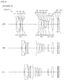
- Example 1 is described using Figs. 1(W), 1(M) and 1(T) and 2A to 2C , and Table 1.
- the zoom lens ZL (ZL1) according to Example 1 is composed of, in order from the object as shown in Fig.1(W), 1(M) and 1(T) , a first lens group G1 having a negative refractive power, a second lens group G2 having a positive refractive power, a third lens group G3 having a negative refractive power, and a fourth lens group G4 having a positive refractive power.
- the first lens group G1 is composed of, in order from an object, a meniscus-shaped negative lens L11 having a concave surface facing an image, a biconcave negative lens L12, and a meniscus-shaped positive lens L13 having a convex surface facing an object. Note that an image side surface of the negative lens L11 has an aspherical surface.
- the second lens group G2 is composed of, in order from an object, a biconvex positive lens L21, an aperture stop S aiming at adjusting a quantity of light, a cemented lens composed of a biconcave positive lens L22 and a biconcave negative lens L23, a biconvex positive lens L24, and a biconvex positive lens L25.
- both side surfaces of the positive lens L21 have an aspherical surface.
- an image side surface of the positive lens L24 has an aspherical surface.
- the third lens group G3 is composed of a meniscus-shaped negative lenses L31 having a concave surface facing the image.
- the fourth lens group G4 is composed of a meniscus-shaped positive lenses L41 having a convex surface facing the object. Note that an object side surface of the positive lens L41 has an aspherical surface.
- a filter group FL is disposed on the image side of the fourth lens group G4, and is composed of low pass filters, infrared cut filters, etc. for cutting spatial frequency more than marginal resolution of a solid-state image sensing device, such as CCDs disposed on the image surface I.
- the zoom lens ZL1 In the zoom lens ZL1 according to the present example, all the lens groups from the first lens group G1 to the fourth lens group G4 move upon zooming from a wide-angle end state (W) to a telephoto end state (T) so that distances between each lens group change.
- the first lens group G1 once moves to the image side in a manner of drawing a locus of a convex on the image side, afterwards moves to the object side.
- the second lens group G2 moves to the object side.
- the third lens group G3 moves to the object side.
- the fourth lens group G4 moves to the object side.
- a distance between the first lens group G1 and the second lens group G2 decreases, a distance between the second lens group G2 and the third lens group G3 decreases, and a distance between the third lens group G3 and the fourth lens group G4 increases.
- Table 1 Values of each data in Example 1 are shown in Table 1 below.
- the surface numbers 1 to 24 in Table 1 correspond to each optical surface of m1 to m24 indicated in Fig.1(W), 1(M) and 1(T) .
- Table 1 [General Data] Zoom ratio 2.77 Wide-angle end Intermediate focal point Telephoto end f 1.00 1.53 2.77 Fno 3.39 4.15 5.96 ⁇ 43.1 30.4 17.9 Y 0.89 0.89 0.89 BF 0.57 0.88 1.65 TL 5.44 5.03 5.53 [Lens Data] Surface number R D nd vd Object Surface ⁇ 1 2.7607 0.0859 1.80610 40.74 *2 0.7655 0.5706 3 -5.9880 0.0675 1.58913 61.22 4 7.5124 0.0123 5 1.7607 0.2147 1.80809 22.74 6 5.0958 D6(variable) *7 0.8712 0.1718 1.58913 61.20 *8 -7.6237 0.0123 9 ⁇ 0.1350 (stop S
- Conditional expression 1 D 3 W / D 3 T 0.367
- Conditional expression 2 M 3 / M 4 0.571
- Conditional expression 3 BFw / fw 2 + ft 2 1 / 2 0.192
- Conditional expression 4 ⁇ dw / ⁇ dt 1.256
- Conditional expression 5 f 4 / fw 7.834
- Conditional expression 6 ⁇ f 1 / f 2 1.177
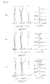
- Fig.2(a) to 2(c) illustrate graphs showing various aberrations (spherical aberration, astigmatism, distortion aberration, coma aberration, and lateral chromatic aberration) of zoom lens ZL1 according to Example 1.
- Fig. 2 (a) illustrates graphs showing various aberrations upon focusing on infinity in the wide-angle end state of Example 1
- Fig.2(b) illustrates graphs showing various aberrations upon focusing on infinity in the intermediate focal length state of Example 1
- Fig.2(c) illustrates graphs showing various aberrations upon focusing on infinity in the telephoto end state of Example 1.
- FNO means a F number
- A means a half angle of view against each image height (unit: degree)
- d means d-line
- g means g-line
- C means C-line
- F means aberration in F-line.
- what is not described means aberration according to d-line.
- a solid line indicates a sagittal image plane and a dashed line indicates a meridional image plane. Note that also in graphs showing aberration of each example described below, the same signs are used as those in the present example.
- Example 2 is explained using Fig.3(W), 3(M) and 3 ( T ) and 4A, 4B and 4C, and Table 2.
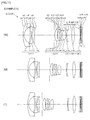
- the zoom lens ZL (ZL2) according to Example 2 is composed of, in order from an object as shown in Fig. 3 , a first lens group G1 having a negative refractive power, a second lens group G2 having a positive refractive power, a third lens group G3 having a negative refractive power, and a fourth lens group G4 having a positive refractive power.
- the first lens group G1 is composed of, in order from the object, a meniscus-shaped negative lens L11 having a concave surface facing the image, a biconcave negative lens L12, and a meniscus-shaped positive lens L13 having a convex surface facing the object. Note that an image side surface of the negative lens L11 has an aspherical surface.
- the second lens group G2 is composed of, in order from the object, an aperture stop S aiming at adjusting a quantity of light, a biconvex positive lens L21, and a cemented lens of a biconvex positive lens L22 and a biconcave negative lens L23, and a biconvex positive lens L24. Note that both side surfaces of the positive lens L21 have an aspherical surface.
- the third lens group G3 is composed of a biconcave negative lenses L31.
- the fourth lens group G4 is composed of a meniscus-shaped positive lenses L41 having a convex surface facing the object. Note that an object side surface of the positive lens L41 has an aspherical surface.
- the filter group FL is arranged on the image side of the fourth lens group G4, and is composed of a low pass filter, an infrared cut filter, etc. for cutting a spatial frequency more than marginal resolution of a solid-state image sensing device such as a CCD disposed on the image surface I.
- the zoom lens ZL2 In the zoom lens ZL2 according to the present example, all the lens groups from the first lens group G1 to the fourth lens group G4 move upon zooming from the wide-angle end state (W) to the telephoto end state (T) so that distances between each lens group change.
- the first lens group G1 once moves to the image side in a manner of drawing a locus of a convex on the image side, afterwards, moves to the object side.
- the second lens group G2 moves to the object side.
- the third lens group G3 moves to the object side.
- the fourth lens group G4 moves to the object side.
- a distance between the first lens group G1 and the second lens group G2 decreases, a distance between the second lens group G2 and the third lens group G3 decreases, and a distance between the third lens group G3 and the fourth lens group G4 increases.
- Conditional expression 1 D 3 W / D 3 T 0.868
- Conditional expression 2 M 3 / M 4 0.910
- Conditional expression 3 BFw / fw 2 + ft 2 1 / 2 0.335
- Conditional expression 4 ⁇ dw / ⁇ dt 1.546
- Conditional expression 5 f 4 / fw 7.971
- Conditional expression 6 ⁇ f 1 / f 2 1.033
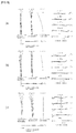
- Fig. 4 (a), 4(b) and 4(c) illustrate graphs showing various aberrations (spherical aberration, astigmatism, distortion aberration, coma aberration, and lateral chromatic aberration) of zoom lens ZL2 according to Example 2.
- Fig. 4 (a) illustrates graphs showing various aberrations upon focusing on infinity in the wide-angle end state of Example 2
- Fig.4(b) illustrates graphs showing various aberrations upon focusing on infinity in the intermediate focal length state of Example 2
- Fig.4(c) illustrates graphs showing various aberrations upon focusing on infinity in the telephoto end state of Example 2.
- Example 3 is explained using Fig.5(W), 5(M) and 5(T) and 6A to 6C, and Table 3.
- the zoom lens ZL (ZL3) according to Example 3 is composed of, in order from the object as shown in Fig.5(W), 5(M) and 5(T) , a first lens group G1 having a negative refractive power, a second lens group G2 having a positive refractive power, a third lens group G3 having a negative refractive power, and a fourth lens group G4 having a positive refractive power.
- the first lens group G1 is composed of, in order from the object, a meniscus-shaped negative lens L11 having a concave surface facing an image side, a biconcave negative lens L12, and a meniscus-shaped positive lens L13 having a concave surface facing the object. Note that an image side surface of the negative lens L11 has an aspherical surface.
- the second lens group G2 is composed of, in order from the object, a biconvex positive lens L21, an aperture stop S aiming at adjusting a quantity of light, a cemented lens composed of a biconvex positive lens L22 and a biconcave negative lens L23, a biconvex positive lens L24, and a biconvex positive lens L25. Note that both side surfaces of the positive lens L21 have an aspherical surface.
- the third lens group G3 is composed of a biconcave negative lenses L31.
- the fourth lens group G4 is composed of a meniscus-shaped positive lenses L41 having a convex surface facing the object side. Note that an object side surface of the positive lens L41 has an aspherical surface.
- the filter group FL is arranged on the image side of the fourth lens group G4, and is composed of a low pass filter, an infrared cut filter, etc. for cutting a spatial frequency more than marginal resolution of a solid-state image sensing device, such as a CCD disposed on the image surface I.
- the zoom lens ZL3 In the zoom lens ZL3 according to the present example, all the lens groups from the first lens group G1 to the fourth lens group G4 move upon zooming from the wide-angle end state to the telephoto end state so that distances between each lens group change.
- the first lens group G1 once moves to the image side in a manner of drawing a locus of a convex, afterwards moves to the object side.
- the second lens group G2 moves to the object side.
- the third lens group G3 moves to the object side.
- the fourth lens group G4 moves to the object side. At this point, a distance between the first lens group G1 and the second lens group G2 decreases, and a distance between the second lens group G2 and the third lens group G3 increases.
- Fig.6(a) to 6(c) illustrate graphs showing various aberrations (spherical aberration, astigmatism, distortion aberration, coma aberration, and lateral chromatic aberration) of zoom lens ZL3 according to Example 3.
- Fig. 6 (a) illustrates graphs showing various aberrations upon focusing on infinity in the wide-angle end state of Example 3
- Fig.6(b) illustrates graphs showing various aberrations upon focusing on infinity in the intermediate focal length state of Example 3
- Fig.6(c) illustrates graphs showing various aberrations upon focusing on infinity in the telephoto end state of Example 3.
- it is understandable that various aberrations are properly corrected, and this has outstanding optical performance.
- Example 4 is explained using Fig.7(W), 7(M) and 7(T) , Fig. 8 (a) to 8(c) , and Table 4.
- the zoom lens ZL (ZL4) according to Example 4 is composed of, in order from an object as shown in Fig. 7(W), 7(M) and 7(T) , a first lens group G1 having a negative refractive power, a second lens group G2 having a positive refractive power, a third lens group G3 having a negative refractive power, a fourth lens group G4 having a positive refractive power, and a fifth lens group G5 having a negative refractive power.
- the first lens group G1 is composed of, in order from the object, a meniscus-shaped negative lens L11 having a concave surface facing the image, a biconcave negative lens L12, and a meniscus-shaped positive lens L13 having a convex facing the object.
- a meniscus-shaped negative lens L11 having a concave surface facing the image
- a biconcave negative lens L12 having a convex facing the object.
- an object side surface of the negative lens L11 has an aspherical surface.
- an image side surface of the positive lens L12 has an aspherical surface.
- the second lens group G2 is composed of, in order from the object, an aperture stop S aiming at adjusting a quantity of light, a biconvex positive lens L21, a cemented lens composed of a meniscus-shaped positive lens L22 having a convex surface facing the object and a meniscus-shaped negative lens L23 having a concave surface facing the image, a cemented lens composed of a meniscus-shaped negative-lens lens L24 having a concave surface facing the image and a biconvex positive lens L25. Note that both side surfaces of the positive lens L21 have an aspherical surface.
- the third lens group G3 is composed of a biconcave negative lenses L31. Note that an image side surface of the negative lens L31 has an aspherical surface.
- the fourth lens group G4 is composed of a biconvex positive lenses L41.
- the fifth lens group G5 is composed of a meniscus-shaped negative lenses L51 having a concave surface facing the object.
- the filter group FL is arranged on the image side of the fifth lens group G5, and is composed of a low pass filter, an infrared cut filter, etc. for cutting spatial frequency more than marginal resolution of a solid-state image sensing device such as a CCD disposed on the image surface I.
- the zoom lens ZL4 upon zooming from the wide-angle end state (W) to the telephoto end state (T), the first lens group G1 to the fourth lens group G4 move so that distances between each lens group change. Specifically speaking, the first lens group G1 once moves to the image side in a manner of drawing a locus of a convex, and moves to the image side. The second lens group G2 moves to the object side. The third lens group G3 moves to the image side. The fourth lens group G4 moves to the image side. The fifth lens group G5 is fixed.
- a distance between the first lens group G1 and the second lens group G2 decreases, a distance between the second lens group G2 and the third lens group G3 increases, a distance between the third lens group G3 and the fourth lens group G4 once increases and afterwards decreases, and a distance between the fourth lens group G4 and the fifth lens group G5 decreases.
- Fig.8(a) to 8(c) illustrate graphs showing various aberrations (spherical aberration, astigmatism, distortion aberration, coma aberration, and lateral chromatic aberration) of zoom lens ZL4 according to Example 4.
- Fig.8(a) illustrates graphs showing various aberrations upon focusing on infinity in the wide-angle end state of Example 4
- Fig.8(b) illustrates graphs showing various aberrations upon focusing on infinity in the intermediate focal length state of Example 4
- Fig.8(c) illustrates graphs showing various aberrations upon focusing on infinity in the telephoto end state of Example 4.
- the zoom lens ZL4 according to Example 4 is properly corrected with various aberrations, and has outstanding optical performance.
- Example 5 is explained using Fig.9(W), 9(M) and 9(T) , Fig.10(a) to 10(c) , and Table 5.
- the zoom lens ZL (ZL5) according to Example 5 is composed of, in order from an object as shown in Fig.9(W), 9(M) and 9(T) , a first lens group G1 having a negative refractive power, a second lens group G2 having a positive refractive power, a third lens group G3 having a negative refractive power, and a fourth lens group G4 having a positive refractive power.
- the first lens group G1 is composed of, in order from the object, a meniscus-shaped negative lens L11 having a concave surface facing an image, a biconcave negative lens L12, a cemented lenses composed of a meniscus-shaped positive lens L13 having a convex surface facing the object and a meniscus-shaped negative lens L14 having a concave surface facing the image.
- both side surfaces of the negative lens L11 have an aspherical surface.
- both side surfaces of the negative lens L12 have an aspherical surface.
- the second lens group G2 is composed of, in order from the object, an aperture stop S aiming at adjusting the quantity of light, a biconvex positive lens L21, a cemented lens composed of a biconvex positive lens L22 and a biconcave negative lens L23, and a biconvex positive lens L24. Note that both side surfaces of the positive lens L21 have an aspherical surface.
- the third lens group G3 is composed of a meniscus-shaped negative lenses L31 having a concave surface facing the image. Note that an image side surface of the positive lens L31 has an aspherical surface.
- the fourth lens group G4 is composed of a biconvex positive lenses L41. Note that an object side surface of the positive lens L41 has an aspherical surface.
- the filter group FL is arranged on the image side of the fourth lens group G4, and is composed of a low pass filter, an infrared cut filter, etc. for cutting spatial frequency more than marginal resolutions of a solid-state image sensing device, such as a CCD disposed on the image surface I.
- the lens groups from the first lens group G1 to the fourth lens group G4 move so that distances between each lens group change.
- the first lens group G1 moves to the image side.
- the second lens group G2 moves to the object side.
- the third lens group G3 moves to the object side.
- the fourth lens group G4 moves to the object side.
- a distance between the first lens group G1 and the second lens group G2 decreases, a distance between the second lens group G2 and the third lens group G3 increases, and a distance between the third lens group G3 and the fourth lens group G4 increases.
- Fig.10(a) to 10(c) illustrate graphs showing various aberrations (spherical aberration, astigmatism, distortion aberration, coma aberration, and lateral chromatic aberration) of zoom lens ZL5 according to Example 5.
- Fig. 10 (a) illustrates graphs showing various aberrations upon focusing on infinity in the wide-angle end state of Example 5
- Fig.10(b) illustrates graphs showing various aberrations upon focusing on infinity in the intermediate focal length state of Example 5
- Fig.10(c) illustrates graphs showing various aberrations upon focusing on infinity in the telephoto end state of Example 5.
- it is understandable that various aberrations are properly corrected, and this has outstanding optical performance.
- Example 6 is described using Fig. 11(W), 11(M) and 11(T) , Fig.12(a) to 12(c) , and Table 6.
- the zoom lens ZL (ZL6) according to Example 6 is composed of, in order from the object as shown in Fig. 11(W), 11(M) and 11(T) , a first lens group G1 having a negative refractive power, a second lens group G2 having a positive refractive power, a third lens group G3 having a negative refractive power, a fourth lens group G4 having a positive refractive power, a the fifth lens group G5 having a negative refractive power.
- the first lens group G1 is composed of, in order from the object, a meniscus-shaped negative lens L11 having a concave surface facing the image, a cemented lens composed of a meniscus-shaped positive lens L12 having a convex surface facing the image and a biconcave negative lens L13, and a meniscus-shaped positive lens L14 having a convex surface facing the object.
- an image side surface of the negative lens L11 has an aspherical surface.
- the second lens group G2 is composed of, in order from the object, an aperture stop S aiming at adjusting a quantity of light, a biconvex positive lens L21, a cemented lens composed of a meniscus-shaped positive lens L22 having a convex surface facing the object and a meniscus-shaped negative lens L23 having a concave surface facing the image, a cemented lens composed of a meniscus-shaped negative lens L24 having a concave surface facing the image and a biconvex positive lens L25.Note that both side surfaces of the positive lens L21 have an aspherical surface.
- the third lens group G3 is composed of a meniscus-shaped negative lenses L31 having a concave surface facing the image. Note that an image side surface of the negative lens L31 has an aspherical surface.
- the fourth lens group G4 is composed of a biconvex positive lenses L41.
- the fifth lens group G5 is composed of the meniscus-shaped negative lenses L51 having a concave surface facing the object.
- the filter group FL is arranged on the image side of the fifth lens group G5, and is composed of a low pass filter, an infrared cut filter, etc. for cutting spatial frequency more than marginal resolution of a solid-state image sensing device, such as a CCD disposed on the image surface I.
- the lens groups from the first lens group G1 to the fourth lens group G4 move so that distances between each lens group change.
- the first lens group G1 once moves to the image side in a manner of drawing a locus of a convex on the image side, and afterwards moves to the object side.
- the second lens group G2 moves to the object side.
- the third lens group G3 moves to the image side.
- the fourth lens group G4 moves to the image side.
- the fifth lens group G5 is fixed.
- a distance between the first lens group G1 and the second lens group G2 decreases, a distance between the second lens group G2 and the third lens group G3 increases, a distance between the third lens group G3 and the fourth lens group G4 once increases and afterwards decreases, and a distance between the fourth lens group G4 and the fifth lens group G5 decreases.
- Fig.12(a) to 12(c) illustrate graphs showing various aberrations (spherical aberration, astigmatism, distortion aberration, coma aberration, and lateral chromatic aberration) of the zoom lens ZL6 according to Example 6.
- Fig.12(a) illustrates graphs showing various aberrations upon focusing on infinity in the wide-angle end state of Example 6
- Fig.12(b) illustrates graphs showing various aberrations upon focusing on infinity in the intermediate focal length state of Example 6
- Fig.12(c) illustrates graphs showing various aberrations upon focusing on infinity in the telephoto end state of Example 6.
- each graph showing aberrations in the zoom lens ZL6 according to Example 6, it is understandable that various aberrations are properly corrected, and this has outstanding optical performance.
- Example 7 is described using Fig. 13(W), 13(M) and 13(T) , Fig.14 (a) to 14 (c) , and Table 7.
- the zoom lens ZL (ZL7) according to Example 7 is composed of, in order from the object as shown in Fig. 13(W), 13(M) and 13(T) , a first lens group G1 having a negative refractive power, a second lens group G2 having a positive refractive power, a third lens group G3 having a negative refractive power, and a fourth lens group G4 having a positive refractive power.
- the first lens group G1 is composed of, in order from the object, a meniscus-shaped negative lens L11 having a concave surface facing the image, a biconcave negative lens L12, and a meniscus-shaped positive lens L13 having a convex surface facing the object.
- both side surfaces of the negative lens L11 have an aspherical surface.
- both side surfaces of the negative lens L12 have an aspherical surface.
- the second lens group G2 is composed of, in order from the object, an aperture stop S aiming at adjusting a quantity of light, a biconvex positive lens L21, a cemented lens composed of a biconvex positive lens L22 and a biconcave negative lens L23, and a biconvex positive lens L24. Note that both side surfaces of the positive lens L21 have an aspherical surface.
- the third lens group G3 is composed of, in order from the object, a cemented lenses composed of a meniscus-shaped positive lens L31 having a convex surface facing the object and a meniscus-shaped negative lens L32 having a concave surface facing the image. Note that an image side surface of the negative lens L32 has an aspherical surface.
- the fourth lens group G4 is composed of an biconvex positive lenses L41. Note that an object side surface of the positive lens L41 has an aspherical surface.
- the filter group FL is arranged on the image side of the fourth lens group G4, and is composed of a low pass filter, an infrared cut filter, etc. for cutting spatial frequency more than marginal resolution of a solid-state image sensing device, such as a CCD disposed on the image surface I.
- the zoom lens ZL7 upon zooming from the wide-angle end state (W) to the telephoto end state (T), all lens groups from the first lens group G1 to the fourth lens group G4 move so that distances between each lens group change. Specifically speaking, the first lens group G1 moves to the image side. The second lens group G2 moves to the object side. The third lens group G3 moves to the object side. The fourth lens group G4 once moves to the image side in a manner of drawing a locus of a convex, and afterwards moves to the object side. At this point, a distance between the first lens group G1 and the second lens group G2 decreases, a distance between the second lens group G2 and the third lens group G3 increases, and a distance between the third lens group G3 and the fourth lens group G4 increases.
- Fig.14(a) to 14(c) illustrate graphs showing various aberrations (spherical aberration, astigmatism, distortion aberration, coma aberration, and lateral chromatic aberration) of zoom lens ZL7 according to Example 7.
- Fig. 14 (a) illustrates graphs showing various aberrations upon focusing on infinity in the wide-angle end state of Example 7
- Fig.14(b) illustrates graphs showing various aberrations upon focusing on infinity in the intermediate focal length state of Example 7
- Fig.14(c) illustrates graphs showing various aberrations upon focusing on infinity in the telephoto end state of Example 7.
- each graph showing aberrations in the zoom lens ZL7 according to Example 7, it is understandable that various aberrations are properly corrected, and this has outstanding optical performance.
- an angle of view in the wide-angle end state is approximately 84 degrees, thus it is possible to provide a zoom lens having outstanding optical performance.
- a lens group means a part that has at least one lens separated at an air interval which changes at the time of focusing or zooming.
- a focusing lens group is configured to focus on a short distance object from an infinity object by moving a single or a plurality of lens group(s), or a partial lens group in an optical axis direction.
- This focusing lens group is also applicable to autofocus, and is also suitable for motor drive for autofocus (using an ultrasonic motor, etc.) .
- the third lens group G3 or the fourth lens group G4 is used as a focusing lens group.
- a vibration control lens group is configured to move a lens group or a partial lens group in manner of having a component in a direction perpendicular to the axis direction, or rotate and move (swing) it in a direction within a surface including the axis direction so that image blur due to camera shake is corrected.
- the second lens group G2 or the third lens group G3 is used as a vibration control lens group.
- a lens surface is formed with a spherical surface or a plane, or formed in an aspherical surface.
- a lens surface has a spherical surface or a plane, it is possible to easily have lens processing and an assembly adjustment, and to prevent degradation of optical performance due to errors of the processing and the assembly adjustment, and it is preferable.
- a lens surface has an aspherical surface
- the aspherical surface is formed as any one of an aspherical surface which is formed through grinding processing, a glass mold aspherical surface which glass is formed into a aspherical surface configuration using a mold, and a complexed aspherical surface which a resin is formed on a surface of glass and formed in a aspherical surface configuration.
- a lens surface is formed as a diffractive surface, additionally a lens is formed as a graded-index lens (GRIN lens) or a plastic lens.
- GRIN lens graded-index lens
- the aperture stop S is preferable to be disposed near the second lens group G2, however this is substituted using a frame of a lens instead of providing a member as an aperture stop.
- a reflection reducing film having high transmissivity in a wide wavelength band is formed on each lens surface in order to reduce flare and ghosting and attain high optical performance with high contrast.
Landscapes
- Physics & Mathematics (AREA)
- General Physics & Mathematics (AREA)
- Optics & Photonics (AREA)
- Nonlinear Science (AREA)
- Lenses (AREA)
Abstract

Description
- The present invention relates to a zoom lens, optical apparatus, and a manufacturing method of the zoom lens.
- Conventionally, small zoom lenses are proposed (for example, refer to Patent Document 1).
- Patent Document 1: Japanese Laid-Open Patent Publication No.
2012-027283A - In recent years, regarding zoom lenses, an angle of view in a wide-angle end state is further expected to be widen while achieving downsizing.
- The present invention is derived in view of such a problem, and aims to provide a zoom lens, an optical apparatus, and a manufacturing method of the zoom lens which is small, however has a wide-angle of view in a wide-angle end state with outstanding optical performance.
- In order to solve such a purpose, a zoom lens according to the present invention, comprises, in order from an object, a first lens group having a negative refractive power, a second lens group having a positive refractive power, a third lens group having a negative refractive power, and a fourth lens group having a positive refractive power, wherein the first lens group, the second lens group, the third lens group, and the fourth lens group move on an optical axis so that zooming is performed by changing distances between each lens group, wherein the first lens group comprises a negative lens disposed closest to the object, a negative lens, and a positive lens, wherein the following conditional expressions is satisfied:

- where D3W denotes an air interval between the third lens group and the fourth lens group in a wide-angle end state, and
- D3T denotes an air interval between the third lens group and the fourth lens group in a telephoto end state.
- In the zoom lens according to the present invention, it is preferable that the following conditional expression is satisfied:

- where M3 denotes an amount of movement on the optical axis of the third lens group upon zooming from the wide-angle end state to the telephoto end state, and
- M4 denotes an amount of movement on the optical axis of the fourth lens group upon zooming from the wide-angle end state to the telephoto end state.
- In the zoom lens according to the present invention, it is preferable that the following conditional expression is satisfied:

- where BFw denotes an air equivalent distance from a lens rear end surface of the zoom lens in the wide-angle end state to an image surface thereof,
- fw denotes a focal length of the zoom lens in the wide-angle end state, and
- ft denotes a focal length of the zoom lens in the telephoto end state.
- In the zoom lens according to the present invention, it is preferable that the following conditional expression is satisfied:

- where Edw denotes a distance from a lens front end surface to the lens rear end surface of the zoom lens in the wide-angle end state, and
- Edt denotes a distance from the lens front end surface to the lens rear end surface of the zoom lens in the telephoto end state.
- In the zoom lens according to the present invention, it is preferable that the first lens group is composed of, in order from the object, a meniscus-shaped negative lens having a concave surface facing an image, a biconcave negative lens, and a meniscus-shaped positive lens having a convex surface facing the object.
- In the zoom lens according to the present invention, it is preferable that the fourth lens group is composed of one lens, wherein the following conditional expression is satisfied:

- where f4 denotes a focal length of the fourth lens group, and
- fw denotes a focal length of the zoom lens in the wide-angle end state.
- In the zoom lens according to the present invention, it is preferable that the following conditional expression is satisfied:

- where f1 denotes a focal length of the first lens group, and
- f2 denotes a focal length of the second lens group.
- In the zoom lens according to the present invention, it is preferable that the third lens group is composed of a cemented lens having a negative refractive power.
- In the zoom lens according to the present invention, it is preferable that the third lens group is composed of one negative lens.
- In the zoom lens according to the present invention, it is preferable that the second lens group comprises a positive lens closest to the object.
- In the zoom lens according to the present invention, it is preferable that the second lens group comprises, in order from the object, a positive lens, a cemented lens which is composed of a positive lens and a negative lens.
- In the zoom lens according to the present invention, it is preferable that the second lens group comprises a positive lens closest to the object, wherein the positive lens has an aspherical surface.
- The optical apparatus according to the present invention is equipped with any one of the above mentioned zoom lenses.
- A manufacturing method of a zoom lens according to the present invention is a manufacturing method of a zoom lens comprising, in order from an object, a first lens group having a negative refractive power, a second lens group having a positive refractive power, a third lens group having a negative refractive power, and a fourth lens group having a positive refractive power, wherein the first lens group, the second lens group, the third lens group, and the fourth lens group move on an optical axis so that zooming is performed by changing distances between each lens group thereof, wherein the first lens group comprises a negative lens disposed closest to the object, a negative lens, and a positive lens, wherein each lens is arranged so that the following conditional expression is satisfied:

- where D3W denotes an air interval between the third lens group and the fourth lens group in the wide-angle end state, and
- D3T denotes an air interval between the third lens group and the fourth lens group in the telephoto end state.
- In the manufacturing method of the zoom lens according to the present invention, it is preferable that each lens is disposed in a lens-barrel so that the following conditional expression is satisfied:

- where M3 denotes an amount of movement on the optical axis of the third lens group upon zooming from the wide-angle end state to the telephoto end state, and
- M4 denotes an amount of movement on the optical axis of the fourth lens group upon zooming from the wide-angle end state to the telephoto end state.
- In the manufacturing method of the zoom lens according to the present invention, it is preferable that each lens is arranged in the lens-barrel so that the following conditional expression is satisfied:

- where BFw denotes an air equivalent distance from the lens rear end surface of the zoom lens in the wide-angle end state to an image surface thereof,
- fw denotes a focal length of the zoom lens in the wide-angle end state, and
- ft denotes a focal length of the zoom lens in the telephoto end state.
- In the manufacturing method of the zoom lens according to the present invention, it is preferable that each lens is arranged in the lens-barrel so that the following conditional expression is satisfied:

- where Edw denotes a distance from the lens front end surface to the lens rear end surface of the zoom lens in the wide-angle end state thereof, and
- Edt denotes a distance from the lens front end surface to the lens rear end surface of the zoom lens in the telephoto end state thereof.
- According to the present invention, it is possible to provide a zoom lens, an optical apparatus, and a manufacturing method of the zoom lens which is small, however has a wide-angle of view in the wide-angle end state, and outstanding optical performance.
-
-
Fig.1(W), 1(M) and 1(T) are sectional views illustrating a configuration of a zoom lens according to Example 1, whereFig.1(W) depicts a position of each lens group in a wide-angle end state,Fig.1(M) depicts that in an intermediate focal length state, andFig.1(T) depicts that in a telephoto end state. -
Fig. 2(a) to 2(c) illustrate graphs showing various aberrations of the zoom lens according to Example 1, whereFig. 2 (a) depicts graphs showing various aberrations upon focusing infinity in the wide-angle end state,Fig.2(b) depicts those in the intermediate focal length state, andFig. 2 (c) illustrates those in the telephoto end state. -
Fig.3(W), 3(M) and 3(T) are sectional views illustrating a configuration of a zoom lens according to Example 2, whereFig. 3(W) depicts a position of each lens group in a wide-angle end state,Fig.3(M) depicts that in an intermediate focal length state, andFig.3(T) depicts that in a telephoto end state. -
Fig.4(a) to 4(c) illustrate graphs showing various aberrations of the zoom lens according to Example 2, whereFig.4 (a) depicts graphs showing various aberrations upon focusing infinity in the wide-angle end state,Fig.4(b) depicts those in the intermediate focal length state, andFig. 4 (c) depicts those in the telephoto end state. -
Fig.5(W), 5(M) and 5(T) are sectional views illustrating a configuration of a zoom lens according to Example 3, whereFig. 5(W) depicts a position of each lens group in a wide-angle end state,Fig.5(M) depicts that in an intermediate focal length state, andFig.5(T) depicts that in a telephoto end state. -
Fig.6(a) to 6(c) illustrate graphs showing various aberrations of the zoom lens according to Example 3, whereFig. 6 (a) depicts graphs showing various aberrations upon focusing infinity in the wide-angle end state,Fig.6(b) depicts ones in the intermediate focal length state, andFig. 6 (c) depicts those in the telephoto end state. -
Fig. 7(W), 7(M) and 7(T) are sectional views illustrating a configuration of a zoom lens according to Example 4 , whereFig. 7(W) depicts a position of each lens group in a wide-angle end state,Fig.7(M) depicts that in an intermediate focal length state, andFig.7(T) depicts that in a telephoto end state. -
Fig.8(a) to 8(c) illustrate graphs showing various aberrations of the zoom lens according to Example 4, whereFig. 8 (a) depicts graphs showing various aberrations upon focusing infinity in the wide-angle end state,Fig.8(b) depicts those in the intermediate focal length state, andFig. 8 (c) depicts those in the telephoto end state. -
Fig.9(W), 9(M) and 9(T) are sectional views illustrating a configuration of a zoom lens according to Example 5, whereFig. 9(W) depicts a position of each lens group in a wide-angle end state,Fig.9(M) depicts that in an intermediate focal length state, andFig.9(T) depicts that in a telephoto end state. -
Fig.10(a) to 10(c) illustrate graphs showing various aberrations of the zoom lens according to Example 5, whereFig. 10 (a) depicts graphs showing various aberrations upon focusing infinity in the wide-angle end state,Fig.10(b) depicts those in the intermediate focal length state, andFig.10 (c) depicts those in the telephoto end state. -
Fig.11(W), 11(M) and 11(T) are sectional views illustrating a configuration of a zoom lens according to Example 6, whereFig.11(W) depicts a position of each lens group in a wide-angle end state,Fig.11(M) depicts that in an intermediate focal length state, andFig. 11(T) depicts that in a telephoto end state. -
Fig.12(a), 12(b) and 12(c) illustrate graphs showing various aberrations of the zoom lens according to Example 6, whereFig. 12 (a) depicts graphs showing various aberrations upon focusing infinity in the wide-angle end state,Fig.12(b) depicts those in the intermediate focal length state, andFig.12(c) depicts those in the telephoto end state. -
Fig.13(W), 13(M) and 13(T) are sectional views illustrating a configuration of a zoom lens according to Example 7, whereFig.13(W) depicts a position of each lens group in a wide-angle end state,Fig.13(M) depicts that in an intermediate focal length state, andFig.13(T) depicts that in a telephoto end state. -
Fig.14(a) to 14(c) illustrate graphs showing various aberrations of the zoom lens according to Example 7, whereFig. 14 (a) depicts graphs showing various aberrations upon focusing infinity in the wide-angle end state, 14 (b) depicts those in the intermediate focal length state, andFig.14(c) depicts those in the telephoto end state. -
Fig.15(a) is a front elevation view of a digital still camera, andFig.15(b) is a rear view of the digital still camera. -
Fig.16 is a sectional view along an arrow A-A' inFig.15(a) . -
Fig. 17 is a flowchart illustrating a manufacturing method of the zoom lens. - An embodiment will now be explained with reference to the drawings. A zoom lens ZL according to the present embodiment comprises, in order from an object as illustrated in
Fig. 1(W), 1(M) and 1(T) , a first lens group G1 having a negative refractive power, a second lens group G2 having a positive refractive power, a third lens group G3 having a negative refractive power, and a fourth lens group G4 having a positive refractive power, wherein the first lens group G1, the second lens group G2, the third lens group G3, and the fourth lens group G4 move on an optical axis so that zooming is performed by changing distances between each lens group, wherein the first lens group G1 comprises a negative lens L11 disposed closest to the object, a negative lens, and a positive lens (corresponding to the lens L12 and the lens L13 inFig.1 ), wherein the following conditional expression (1) is satisfied. - Generally, in designing an imaging optical system such as a photographic lens, etc., it is difficult to attain downsizing synchronously while enlarging an angle of view, in view of correcting various aberrations. However, according to the zoom lens ZL of the present embodiment, it is possible to achieve downsizing while enlarging an angle of view, and to appropriately correct various aberrations such as spherical aberration and coma aberration, etc.

- D3W denotes an air interval between the third lens group G3 and the fourth lens group G4 in the wide-angle end state, and
- D3T denotes an air interval between the third lens group G3 and the fourth lens group G4 in the telephoto end state.
- The conditional expression (1) is a conditional expression which defines an air interval between the third lens group G3 and the fourth lens group G4 in the wide-angle end state and the telephoto end state (a distance on the optical axis from a lens surface closest to the image of the third lens group G3 in the wide-angle end state, to a lens surface closest to the object of the lens group G4) . By satisfying with the conditional expression (1), it is possible to properly correct coma aberration, astigmatism, and lateral chromatic aberration while suppressing a change of an incident angle to the imaging surface by zooming. When deceeding the lower limit of the conditional expression (1), this is an advantageous in favor of correcting coma aberration, astigmatism and lateral chromatic aberration, however, since air intervals between the third lens group G3 and the fourth lens group G4 greatly change in a wide-angle end state and in a telephoto end state, the change of the incident angle to the imaging surface upon zooming becomes great, thus it is not appreciated. When exceeding the upper limit of the conditional expression (1), since it becomes difficult to correct coma aberration, astigmatism, and lateral chromatic aberration while attaining downsizing, thus it is not appreciated.
- In order to ensure the advantageous effect of the present embodiment, it is preferable to set the lower limit of the conditional expression (1) to 0.33. In order to ensure the advantageous effect of the present embodiment, it is preferable to set the lower limit of the conditional expression (1) to 0.36.
- In order to ensure the advantageous effect of the present embodiment, it is preferable to set the upper limit of the conditional expression (1) to 1.05. In order to ensure the advantageous effect of the present embodiment, it is preferable to set the upper limit of the conditional expression (1) to 1.01.
- Regarding the zoom lens ZL according to the present embodiment, it is preferable that the following conditional expression (2) is satisfied:

- where M3 denotes an amount of movement on the optical axis of the third lens group G3 upon zooming from a wide-angle end state to a telephoto end state, and
- M4 denotes an amount of movement on the optical axis of the fourth lens group G4 upon zooming from the wide-angle end state to the telephoto end state.
- A conditional expression (2) is a conditional expression which defines a ratio of an amount of movement of the third lens group G3 and the fourth lens group G4 upon zooming from the wide-angle end state to the telephoto end state. By satisfying the conditional expression (2), it is possible to properly correct coma aberration, astigmatism and lateral chromatic aberration, while suppressing the change of the incident angle to the imaging surface. When deceeding the lower limit of the conditional expression (2), the third lens group G3 and the fourth lens group G4 are placed away from each other in the wide-angle end state, it is difficult to correct astigmatism and lateral chromatic aberration, thus this is not appreciated. When exceeding the upper limit of the conditional expression (2), this is advantageous for correcting chromatic aberration, etc. , however, when performing a focus for downsizing by the third lens group G3 or the forth lens group G4, the refractive power of a focal group must be improved, it is difficult to correct astigmatism and coma aberration, and it is not appreciated.
- In order to ensure the advantageous effect of the present embodiment, it is preferable to set the upper limit of the conditional expression (2) to 0.996.
- In the zoom lens ZL according to the present embodiment, it is preferable that the following conditional expression (3) is satisfied:

- where BFw denotes an air equivalent distance from an lens rear end surface of the zoom lens in the wide-angle end state ZL to an image surface thereof,
- fw denotes a focal length of the zoom lens ZL in the wide-angle end state, and
- ft denotes a focal length of the zoom lens ZL in the telephoto end state.
- A conditional expression (3) is a conditional expression which defines an optical back focus for downsizing and an aberration correction in the zoom lens ZL of the present embodiment. When deceeding the lower limit of the conditional expression (3), it is advantageous for downsizing, however, since there is less distance in which a filter, etc. is disposed between the lens rear end surface and the imaging surface, thus it is not appreciated. Moreover, astigmatism and coma aberration become worse. When exceeding the upper limit of the conditional expression (3), it is advantageous for disposing a filter, etc. , however, it is not appreciated in view of downsizing. Moreover, astigmatism and coma aberration become worse.
- In order to ensure the advantageous effect of the present embodiment, it is preferable to set the lower limit of the conditional expression (3) to 0.08. In order to ensure the advantageous effect of the present embodiment, it is preferable to set the upper limit of the conditional expression (3) to 0.46.
- Regarding the zoom lens ZL according to the present embodiment, it is preferable that the following conditional expression (4) is satisfied:

- where Edw denotes a distance from an lens front end surface to the lens rear end surface of the zoom lens ZL in the wide-angle end state, and
- Edt denotes a distance from the lens front end surface to the lens rear end surface of the zoom lens ZL in the telephoto end state.
- The conditional expression (4) is a conditional expression which defines a change of the incident angle to the imaging surface upon zooming, and a change of a lens thickness appropriate to correct various aberrations. When deceeding the lower limit of the conditional expression (4), it becomes advantageous for downsizing, however since the change of the incident angle to the imaging surface becomes large too much, thus it is not appreciated. Moreover, spherical aberration and coma aberration become worse. When exceeding the upper limit of the conditional expression (4), an incident angle to the imaging surface becomes small, however it is difficult to correct coma aberration and astigmatism, thus this is not appreciated.
- In order to ensure the advantageous effect of the present embodiment, it is preferable to set the lower limit of the conditional expression (4) to 1.03. In order to ensure the advantageous effect of the present embodiment, it is preferable to set the upper limit of the conditional expression (4) to 1.55.
- In the zoom lens ZL according to the present embodiment, it is preferable that the first lens group is composed of, in order from the object, a meniscus-shaped negative lens L11 having a concave surface facing the image, a biconcave negative lens L12, and a meniscus-shape positive lens L13 having a convex surface facing the object.
- With this arrangement, it is possible to properly correct imaging surface curvature, astigmatism, and lateral chromatic aberration in a lens whole system with an angle of view enlarged.
- In the zoom lens ZL according to the present embodiment, it is preferable that the fourth lens group G4 is composed of one lens, and the following conditional expression (5) is satisfied:

- where f4 denotes a focal length of the fourth lens group G4, and
- fw denotes a focal length of the zoom lens ZL in a wide-angle end state.
- The conditional expression (5) is a conditional expression which defines an optimal focal length of the fourth lens group G4 most appropriated for downsizing of the lens and correcting various aberrations. When deceeding the lower limit of the conditional expression (5), since the focal length of the fourth lens group G4 is too short and it is disadvantageous for downsizing the lens, thus it is not appreciated. Moreover, coma aberration and imaging surface curvature become worse. When exceeding the upper limit of the conditional expression (5), it is advantageous for downsizing, however, the incident angle to the imaging surface becomes large, it is not appreciated. Moreover, coma aberration and imaging surface curvature become worse.
- In order to ensure the advantageous effect of the present embodiment, it is appreciated to set the lower limit of the conditional expression (5) to 2.50. In order to ensure the advantageous effect of the present embodiment, it is preferable to set the upper limit of the conditional expression (5) to 8.00.
- In the zoom lens ZL according to the present embodiment, it is preferable that the following conditional expression (6) is satisfied:

- where f1 denotes a focal length of the first lens group G1, and
- f2 denotes a focal length of the second lens group G2.
- The conditional expression (6) is a conditional expression which defines a suitable focal length regarding the first lens group G1 and the second lens group G2 in order to balance downsizing of the lens and correcting aberration. When deceeding the lower limit of the conditional expression (6), the focal length of the first lens group G1 is short in comparison with the focal length of the second lens group G2, thus, it is difficult to correct spherical aberration, and coma aberration, etc. which occurred in the first lens group G1, thus it is not appreciated. When exceeding the upper limit of the conditional expression (6), it is disadvantageous for downsizing, thus it is not appreciated. Moreover, spherical aberration becomes worse.
- In order to ensure the advantageous effect of the present embodiment, it is preferable to set the lower limit of the conditional expression (6) to 1.10. In order to ensure the advantageous effect of the present embodiment, it is appreciated to set the upper limit of the conditional expression (6) to 1.20.
- In the zoom lens ZL according to the present embodiment, it is preferable that the third lens group G3 is composed of a cemented lens having a negative refractive power.
- With this arrangement, it is possible to minimize a coma aberration fluctuation and an imaging surface fluctuation when zooming, while downsizing a lens, and properly correct axial chromatic aberration and a lateral chromatic aberration in a lens whole system.
- In the zoom lens ZL according to the present embodiment, it is preferable that the third lens group G3 is composed of one negative lens.
- With this arrangement, it is possible to correct a coma aberration fluctuation and imaging surface curvature fluctuation when zooming, while downsizing the lens.
- In the zoom lens ZL according to the present embodiment, it is preferable that the second lens group G2 has a positive lens L21 closest to the object.
- With this arrangement, it is possible to properly correct spherical aberration and coma aberration which occurred in the first lens group G1.
- In the zoom lens ZL according to the present embodiment, it is appreciated that the second lens group G2 has, in order from the object, a positive lens L21, and a cemented lens composed of a positive lens L22 and a negative lens L23.
- With this arrangement, it is possible to correct spherical aberration, astigmatism, coma aberration, and chromatic aberration while downsizing the lens.
- In the zoom lens ZL according to the present embodiment, it is preferable that the positive lens L21 arranged closest to the object within the second lens group G2 has an aspherical surface.
- With this arrangement, it is possible to properly correct spherical aberration, astigmatism, and coma aberration while downsizing a lens.
- According to the zoom lens ZL of the present embodiment equipped with the above configurations, although this is small, however it is possible to realize a zoom lens with an angle of view enlarged in the wide-angle end state, and have outstanding optical performance.
-
Fig. 15 (a) and 15 (b) andFig. 16 illustrate configurations of a digital still camera CAM (optical apparatus) as an optical apparatus equipped with the zoom lens ZL. In this digital still camera CAM, when a power button is pressed, a not illustrated shutter of a photographing lens (zoom lens ZL) opens, light from a photographic subject (object) are collected with the zoom lens ZL, and this is imaged by an image element C(for instance, a CCD or a CMOS, etc.) disposed on an image surface I (refer toFig.1 ). The photographic subject image imaged by the image element C is displayed on a liquid crystal display monitor M provided behind the digital still camera CAM. A photographer photos, after deciding a composition of a photographic subject image while looking at the liquid crystal display monitor M, the photographic subject by the image element C by pressing a shutter release button B1, and records and stores it in a not illustrated memory. - The camera CAM is provided with a fill light flushing unit EF which emits fill light when a photographic subject is dark, and a function button B2, etc. used for setting various conditions, etc. of the digital still camera CAM. Although a compact type camera in which a camera CAM and a zoom lens ZL are fabricated together is exampled herewith, it is applicable to a single-lens reflex camera, as an optical apparatus, in which a lens-barrel having the zoom lens ZL is attachable and detachable with a camera body.
- According to the camera CAM of the present embodiment equipped with the above configurations, by having the zoom lens ZL described above as a photographing lens, although this is small, however it is possible to realize a camera with an angle of view in the wide-angle end state enlarged, and having outstanding optical performance.
- Next, referring to
Fig. 17 , a manufacturing method of the zoom lens ZL described above will be outlined. Firstly, each lens is disposed so that the first lens group G1 having a negative refractive power, the second lens group G2 having a positive refractive power, the third lens group G3 having a negative refractive power, and the fourth lens G4 having a positive refractive power are arranged in order from the object in a lens-barrel (Step ST10) . Here, each lens is arranged so that zooming is performed by changing distances between each lens group by moving the first lens group G1, the second lens group G2, the third lens group G3, and the fourth lens group G4 on the optical-axis (Step ST20) . The first lens group G1 is arranged so that this has a negative lens L11 arranged closest to the object, a negative lens, and a positive lens (Step ST30). Each lens is arranged so that the following conditional expression (1) is satisfied (Step ST40):
- where D3W denotes an air interval between the third lens group G3 and the fourth lens group G4 in the wide-angle end state, and
- D3T denotes an air interval between the third lens group G3 and the fourth lens group G4 in the telephoto end state.
- In the manufacturing method of the zoom lens ZL according to the present embodiment, it is preferable to arrange each lens in the lens-barrel so that the above-mentioned conditional expression (2) is satisfied.
- In the manufacturing method of the zoom lens ZL according to the present embodiment, it is preferable to arrange each lens in the lens-barrel so that the above-mentioned conditional expression (3) is satisfied.
- In the manufacturing method of the zoom lens ZL according to the present embodiment, it is preferable to arrange each lens in the lens-barrel so that the above-mentioned conditional expression (4) is satisfied.
- Specifically speaking, in the present embodiment, for example in order from the object as illustrated in
Fig.1(W), 1(M) and 1(T) , the first lens group G1 is composed of the meniscus-shaped negative lens L11 having a concave surface facing the image, the biconcave negative lens L12, the meniscus-shaped positive lens L13 having a concave surface facing the object, the second lens group G2 is composed of the biconvex positive lens L21, an aperture stop S aiming at adjusting a quantity of light, the cemented lens composed of the biconvex positive lens L22 and the biconcave negative lens L23, the biconvex positive lens L24, and the biconvex positive lens L25, the third lens group G3 is composed of the meniscus-shaped negative lens L31 having a concave surface facing the image, and the forth lens group G4 is composed of the meniscus-shaped positive lens L41 having a convex surface facing the object. Each lens is disposed as mentioned above, the zoom lens ZL is manufactured. - According to the manufacturing method of the zoom lens ZL, although this is small, however it is possible to realize a zoom lens with an angle of view in the wide-angle end state enlarged, and having outstanding optical performance.
- Next, each example according to the present embodiment is described referring to the drawings. Tables 1 to 7 are illustrated below, and these show tables of each data in Examples 1 to 7.
- Note that each reference sign to
Fig. 1(W), 1(M) and 1(T) according to Example 1 is independently used for each example in order to avoid the complicated explanation due to increasing the digit number of reference signs. Therefore, even if referred to the same reference sings shared with other drawings according to other examples, this does not necessarily mean they are the same configurations of the other examples. - In each example, as calculation targets of aberration characteristics, C-line (wave length of 656.2730 nm), d-line (wave length of 587.5620 nm), F-line (wave length of 486.1330 nm), and g-line (wave length of 435.8350 nm) are selected.
- In [General Data] in tables, f means a focal length of the lens whole system, Fno means a F number, ω means a half angle of view (maximum incident angle, unit: degree), Y means an image height, BF means a back focus (what is carried out by performing air equivalent of a distance from a lens rear end surface to a paraxial image surface on the optical axis), and TL means a total lens length (what is added with BF to a distance from a lens front end surface to a lens rear end surface on the optical axis).
- In [Lens Data] in tables, a surface number means an order of an optical surface from the object side along a direction in which a ray travels, R means a radius of curvature of each optical surface, D means a distance to the next lens surface, which is a distance on the optical axis from each optical surface to the next optical surface (or an image surface), nd means a refractive index to d-line of material of an optical member, and vd means an Abbe number on the basis of the d-line of material of the optical member. An object surface means a surface of an object, (variable) means a variable distance to the next lens surface, "∞" means a plane or an aperture, (stop S) means an aperture stop S, and an image surface means an image surface I. The refractive index of an air "1.00000" is omitted. In case that an optical surface has an aspherical surface, an "*" sign is given to the surface number, and a paraxial radius of curvature is illustrated in columns of the radius of curvature R.
- In [aspherical surface data] in tables, regarding the aspherical surface shown in [Lens Data], its configuration is indicated with the following expression (a) . X(y) means a distance along the optical axis from a tangent plane in a vertex of an aspherical surface to a location on the aspherical surface in height y, R means a radius of curvature (paraxial radius of curvature) of a standard spherical surface, κ means a cone constant, and Ai means an i-th aspherical surface coefficient. "E-n" means "x10-n." For instance, 1.234E-05 is equal to 1.234x10⁻⁵.

- [variable distance data] in tables show values Di of a valuable distance in each state such as a wide-angle end, an intermediate focal length, or a telephoto end. Note that Di indicates a variable distance between the i-th surface and the (i+1)-th surface.
- In [Lens Group Data] in tables, G means a group number, a group first surface means a surface number closest to an object of each group, a group focal length means a focal length of each group, and a lens configuration length means a distance on the optical axis from a lens surface closest to the object in each group to a lens surface closest to the image.
- [Conditional Expression] in tables shows values corresponding to the conditional expressions (1) to (6).
- Hereinafter, in all general data values, regarding the focal length f shown, a radius of curvature R, a distance to the next lens surface D, and other lengths, etc. "mm" is generally used except a specific request, however a zoom lens is not limited to the above, since equivalent optical performance can be obtained even if the zoom lens is proportionally enlarged or proportionally shrunk. Moreover, the unit is not limited to "mm, "can be used with another appropriate unit.
- The explanations concerning the tables are common among all the examples, thus hereinafter the explanations are omitted.
- Example 1 is described using
Figs. 1(W), 1(M) and 1(T) and2A to 2C , and Table 1. The zoom lens ZL (ZL1) according to Example 1 is composed of, in order from the object as shown inFig.1(W), 1(M) and 1(T) , a first lens group G1 having a negative refractive power, a second lens group G2 having a positive refractive power, a third lens group G3 having a negative refractive power, and a fourth lens group G4 having a positive refractive power. - The first lens group G1 is composed of, in order from an object, a meniscus-shaped negative lens L11 having a concave surface facing an image, a biconcave negative lens L12, and a meniscus-shaped positive lens L13 having a convex surface facing an object. Note that an image side surface of the negative lens L11 has an aspherical surface.
- The second lens group G2 is composed of, in order from an object, a biconvex positive lens L21, an aperture stop S aiming at adjusting a quantity of light, a cemented lens composed of a biconcave positive lens L22 and a biconcave negative lens L23, a biconvex positive lens L24, and a biconvex positive lens L25. Note that both side surfaces of the positive lens L21 have an aspherical surface. Moreover, an image side surface of the positive lens L24 has an aspherical surface.
- The third lens group G3 is composed of a meniscus-shaped negative lenses L31 having a concave surface facing the image.
- The fourth lens group G4 is composed of a meniscus-shaped positive lenses L41 having a convex surface facing the object. Note that an object side surface of the positive lens L41 has an aspherical surface.
- A filter group FL is disposed on the image side of the fourth lens group G4, and is composed of low pass filters, infrared cut filters, etc. for cutting spatial frequency more than marginal resolution of a solid-state image sensing device, such as CCDs disposed on the image surface I.
- In the zoom lens ZL1 according to the present example, all the lens groups from the first lens group G1 to the fourth lens group G4 move upon zooming from a wide-angle end state (W) to a telephoto end state (T) so that distances between each lens group change. Specifically speaking, the first lens group G1 once moves to the image side in a manner of drawing a locus of a convex on the image side, afterwards moves to the object side. The second lens group G2 moves to the object side. The third lens group G3 moves to the object side. The fourth lens group G4 moves to the object side. At this point, a distance between the first lens group G1 and the second lens group G2 decreases, a distance between the second lens group G2 and the third lens group G3 decreases, and a distance between the third lens group G3 and the fourth lens group G4 increases.
- Values of each data in Example 1 are shown in Table 1 below. The
surface numbers 1 to 24 in Table 1 correspond to each optical surface of m1 to m24 indicated inFig.1(W), 1(M) and 1(T) .(Table 1) [General Data] Zoom ratio 2.77 Wide-angle end Intermediate focal point Telephoto end f 1.00 1.53 2.77 Fno 3.39 4.15 5.96 ω 43.1 30.4 17.9 Y 0.89 0.89 0.89 BF 0.57 0.88 1.65 TL 5.44 5.03 5.53 [Lens Data] Surface number R D nd vd Object Surface ∞ 1 2.7607 0.0859 1.80610 40.74 *2 0.7655 0.5706 3 -5.9880 0.0675 1.58913 61.22 4 7.5124 0.0123 5 1.7607 0.2147 1.80809 22.74 6 5.0958 D6(variable) *7 0.8712 0.1718 1.58913 61.20 *8 -7.6237 0.0123 9 ∞ 0.1350 (stop S) 10 0.8747 0.2270 1.52249 59.21 11 -1.9759 0.0491 1.80100 34.92 12 0.6513 0.0982 13 4.9080 0.0920 1.58913 61.20 *14 -8.9252 0.0307 15 4.9080 0.1350 1.48749 70.31 16 -2.1650 D16(variable) 17 6.1350 0.0613 1.58913 61.22 18 2.1027 D18(variable) *19 3.0675 0.1595 1.58913 61.20 20 8.9701 D20(variable) 21 ∞ 0.0429 1.51680 64.20 22 ∞ 0.0920 23 ∞ 0.0429 1.51680 64.20 24 ∞ 0.0307 Image Surface ∞ [Aspherical surface data] Surface Number K A4 A6 A8 A10 2 0.5552 1.82699E-02 4.51869E-02 0.00000E.00 0.00000E.00 7 0.2252 4.23003E-02 3.15591E-02 0.00000E.00 0.00000E.00 8 1.0000 -7.49496E-03 0.00000E.00 0.00000E.00 0.00000E.00 14 1.0000 7.27866E-02 0.00000E.00 0.00000E.00 0.00000E.00 19 1.0000 -1.58968E-03 1.35218E-02 0.00000E.00 0.00000E.00 [Zooming Data] Variable distance Wide-angle end Intermediate focal point Telephoto end D6 1.85061 0.91855 0.13347 D16 0.4329 0.40719 0.34254 D18 0.47104 0.70238 1.28929 D20 0.38777 0.69622 1.47210 [Lens group data] Group number Group first surface Group focal length Lens configuration length G1 1 -1.76643 0.9510 G2 7 1.50036 0.9511 G3 17 -5.46114 0.0613 G4 19 7.83422 0.1595 -


- As shown in Table 1, it is understandable that the conditional expressions (1) to (6) are satisfied regarding the zoom lens ZL1 according to the present example.
-
Fig.2(a) to 2(c) illustrate graphs showing various aberrations (spherical aberration, astigmatism, distortion aberration, coma aberration, and lateral chromatic aberration) of zoom lens ZL1 according to Example 1.Fig. 2 (a) illustrates graphs showing various aberrations upon focusing on infinity in the wide-angle end state of Example 1,Fig.2(b) illustrates graphs showing various aberrations upon focusing on infinity in the intermediate focal length state of Example 1, andFig.2(c) illustrates graphs showing various aberrations upon focusing on infinity in the telephoto end state of Example 1. - In each graph showing aberration, FNO means a F number, and A means a half angle of view against each image height (unit: degree) . d means d-line, g means g-line, C means C-line, and F means aberration in F-line. Moreover, what is not described means aberration according to d-line. In graphs showing astigmatism, a solid line indicates a sagittal image plane and a dashed line indicates a meridional image plane. Note that also in graphs showing aberration of each example described below, the same signs are used as those in the present example.
- As is obvious in each graph showing aberration, in the zoom lens ZL1 according to Example 1, it is understandable that various aberrations are properly corrected, and this has outstanding optical performance.
- Example 2 is explained using
Fig.3(W), 3(M) and 3 (T) and 4A, 4B and 4C, and Table 2. The zoom lens ZL (ZL2) according to Example 2 is composed of, in order from an object as shown inFig. 3 , a first lens group G1 having a negative refractive power, a second lens group G2 having a positive refractive power, a third lens group G3 having a negative refractive power, and a fourth lens group G4 having a positive refractive power. - The first lens group G1 is composed of, in order from the object, a meniscus-shaped negative lens L11 having a concave surface facing the image, a biconcave negative lens L12, and a meniscus-shaped positive lens L13 having a convex surface facing the object. Note that an image side surface of the negative lens L11 has an aspherical surface.
- The second lens group G2 is composed of, in order from the object, an aperture stop S aiming at adjusting a quantity of light, a biconvex positive lens L21, and a cemented lens of a biconvex positive lens L22 and a biconcave negative lens L23, and a biconvex positive lens L24. Note that both side surfaces of the positive lens L21 have an aspherical surface.
- The third lens group G3 is composed of a biconcave negative lenses L31.
- The fourth lens group G4 is composed of a meniscus-shaped positive lenses L41 having a convex surface facing the object. Note that an object side surface of the positive lens L41 has an aspherical surface.
- The filter group FL is arranged on the image side of the fourth lens group G4, and is composed of a low pass filter, an infrared cut filter, etc. for cutting a spatial frequency more than marginal resolution of a solid-state image sensing device such as a CCD disposed on the image surface I.
- In the zoom lens ZL2 according to the present example, all the lens groups from the first lens group G1 to the fourth lens group G4 move upon zooming from the wide-angle end state (W) to the telephoto end state (T) so that distances between each lens group change. Specifically speaking, the first lens group G1 once moves to the image side in a manner of drawing a locus of a convex on the image side, afterwards, moves to the object side. The second lens group G2 moves to the object side. The third lens group G3 moves to the object side. The fourth lens group G4 moves to the object side. At this point, a distance between the first lens group G1 and the second lens group G2 decreases, a distance between the second lens group G2 and the third lens group G3 decreases, and a distance between the third lens group G3 and the fourth lens group G4 increases.
- Values of each data in Example 2 are shown in Table 2 below. The
surface numbers 1 to 22 in Table 2 correspond to each optical surface of m1 to m22 which are illustrated inFig.3(W), 3(M) and 3(T) .(Table 2) [General Data] Zoom ratio 2.94 Wide-angle end Intermediate focal point Telephoto end f 1.00 1.53 2.94 Fno 3.03 3.99 6.03 ω 43.2 30.7 16.9 Y 0.89 0.89 0.89 BF 1.04 1.63 3.29 TL 5.97 5.65 6.48 [Lens Data] Surface number R D nd vd Object surface ∞ 1 2.2883 0.0920 1.80610 40.74 *2 0.7373 0.6564 3 -9.1361 0.0675 1.72916 54.61 4 3.9033 0.0123 5 1.7362 0.2331 1.80809 22.74 6 6.0369 D6(variable) 7 ∞ 0.0307 (stop S) *8 0.8589 0.2822 1.58913 61.20 *9 -7.2780 0.0491 10 1.6834 0.2331 1.58267 46.48 11 -1.8084 0.0675 1.80100 34.92 12 0.7855 0.0859 13 2.5700 0.2025 1.48749 70.31 14 -1.2299 D14(variable) 15 -7.9755 0.0736 1.67300 38.15 16 5.2416 D16(variable) *17 2.8221 0.1411 1.58913 61.22 18 6.9412 D18(variable) 19 ∞ 0.0429 1.51680 64.20 20 ∞ 0.0920 21 ∞ 0.0429 1.51680 64.20 22 ∞ 0.0307 Image surface ∞ [Aspherical surface data] Surface number K A4 A6 A8 A10 2 0.5876 1.48400E-02 2.93833E-02 0.00000E.00 0.00000E.00 8 0.5920 -1.48182E-02 0.00000E.00 1.22878E-01 3.62602E-02 9 1.0000 9.86346E-02 0.00000E.00 0.00000E.00 0.00000E.00 17 1.0000 -1.85798E-02 6.87964E-03 0.00000E.00 0.00000E.00 [Zooming data] Variable distance Wide-angle end Intermediate focal point Telephoto end D6 1.90212 0.98604 0.16214 D14 0.41369 0.35509 0.19202 D16 0.38614 0.44474 0.60782 D18 0.86120 1.45446 3.10802 [Lens group data] Group number Group first surface Group focal length Lens configuration length G1 1 -1.60069 1.0613 G2 7 1.54986 0.9510 G3 15 -4.68917 0.0736 G4 17 7.97097 0.1411 -





- Based on Table 2, the conditional expressions (1) to (6) are satisfied regarding the zoom lens ZL2 according to the present example.
-
Fig. 4 (a), 4(b) and 4(c) illustrate graphs showing various aberrations (spherical aberration, astigmatism, distortion aberration, coma aberration, and lateral chromatic aberration) of zoom lens ZL2 according to Example 2.Fig. 4 (a) illustrates graphs showing various aberrations upon focusing on infinity in the wide-angle end state of Example 2,Fig.4(b) illustrates graphs showing various aberrations upon focusing on infinity in the intermediate focal length state of Example 2, andFig.4(c) illustrates graphs showing various aberrations upon focusing on infinity in the telephoto end state of Example 2. As is obvious in each graph showing aberration, in the zoom lens ZL2 according to Example 2, it is understandable that various aberrations are properly corrected, and this has outstanding optical performance. - Example 3 is explained using
Fig.5(W), 5(M) and 5(T) and 6A to 6C, and Table 3. The zoom lens ZL (ZL3) according to Example 3 is composed of, in order from the object as shown inFig.5(W), 5(M) and 5(T) , a first lens group G1 having a negative refractive power, a second lens group G2 having a positive refractive power, a third lens group G3 having a negative refractive power, and a fourth lens group G4 having a positive refractive power. - The first lens group G1 is composed of, in order from the object, a meniscus-shaped negative lens L11 having a concave surface facing an image side, a biconcave negative lens L12, and a meniscus-shaped positive lens L13 having a concave surface facing the object. Note that an image side surface of the negative lens L11 has an aspherical surface.
- The second lens group G2 is composed of, in order from the object, a biconvex positive lens L21, an aperture stop S aiming at adjusting a quantity of light, a cemented lens composed of a biconvex positive lens L22 and a biconcave negative lens L23, a biconvex positive lens L24, and a biconvex positive lens L25. Note that both side surfaces of the positive lens L21 have an aspherical surface.
- The third lens group G3 is composed of a biconcave negative lenses L31.
- The fourth lens group G4 is composed of a meniscus-shaped positive lenses L41 having a convex surface facing the object side. Note that an object side surface of the positive lens L41 has an aspherical surface.
- The filter group FL is arranged on the image side of the fourth lens group G4, and is composed of a low pass filter, an infrared cut filter, etc. for cutting a spatial frequency more than marginal resolution of a solid-state image sensing device, such as a CCD disposed on the image surface I.
- In the zoom lens ZL3 according to the present example, all the lens groups from the first lens group G1 to the fourth lens group G4 move upon zooming from the wide-angle end state to the telephoto end state so that distances between each lens group change. Specifically speaking, the first lens group G1 once moves to the image side in a manner of drawing a locus of a convex, afterwards moves to the object side. The second lens group G2 moves to the object side. The third lens group G3 moves to the object side. The fourth lens group G4 moves to the object side. At this point, a distance between the first lens group G1 and the second lens group G2 decreases, and a distance between the second lens group G2 and the third lens group G3 increases.
- Values of each data in Example 3 are shown in Table 3 below. The
surface numbers 1 to 24 in Table 3 correspond to each optical surface of m1 to m24 which are shown inFig.5(W), 5(M) and 5(T) .(Table 3) [General Data] Zoom ratio 3.37 Wide-angle end Intermediate focal point Telephoto end f 1.00 1.53 3.37 Fno 2.89 3.57 5.87 ω 44.0 30.8 14.8 Y 0.81 0.85 0.89 BF 1.29 1.62 2.88 TL 5.51 5.15 5.72 [Lens Data] Surface number R D nd vd Object surface ∞ 1 3.0676 0.0736 1.80610 40.77 *2 0.8660 0.5399 3 -3.5156 0.0614 1.72916 54.61 4 7.1326 0.0123 5 2.0247 0.1902 1.80809 22.74 6 13.1350 D6(variable) *7 0.9075 0.2209 1.59201 67.05 *8 -9.6052 0.1411 9 ∞ 0.0123 (stop S) 10 0.9301 0.1902 1.62299 58.12 11 -4.1799 0.0491 1.80100 34.92 12 0.6440 0.0982 13 4.9082 0.0859 1.58913 61.22 14 -4.9775 0.0307 15 3.0676 0.0920 1.58913 61.22 16 -10.3052 D16(variable) 17 -6.1353 0.0491 1.58913 61.22 18 3.4411 D18(variable) *19 2.4541 0.1104 1.62263 58.19 20 5.4478 D20(variable) 21 ∞ 0.0430 1.51680 64.20 22 ∞ 0.0920 23 ∞ 0.0430 1.51680 64.20 24 ∞ 0.0307 Image surface ∞ [Aspherical surface data] Surface number K A4 A6 A8 A10 2 0.8145 6.24280E-03 2.17041E-02 0.00000E.00 0.00000E.00 7 1.0000 -1.15156E-01 -6.71093E-02 -1.33516E-01 0.00000E.00 8 1.0000 4.43207E-03 0.00000E.00 0.00000E.00 0.00000E.00 19 1.0000 -2.42479E-02 2.00563E-02 9.42333E-02 0.00000E.00 [Zooming data] Variable distance Wide-angle end Intermediate focal point Telephoto end D6 1.90947 1.03034 0.04886 D16 0.07479 0.13747 0.49243 D18 0.27637 0.40612 0.33772 D20 1.11507 1.43886 2.70424 [Lens group data] Group number Group first surface Group focal length Lens configuration length G1 1 -1.63500 0.8773 G2 7 1.41112 0.9203 G3 17 -3.73503 0.0491 G4 19 7.07257 0.1104 -


- Based on Table 3, regarding zoom lens ZL3 according to the present example the conditional expressions (1) to (6) are satisfied.
-
Fig.6(a) to 6(c) illustrate graphs showing various aberrations (spherical aberration, astigmatism, distortion aberration, coma aberration, and lateral chromatic aberration) of zoom lens ZL3 according to Example 3.Fig. 6 (a) illustrates graphs showing various aberrations upon focusing on infinity in the wide-angle end state of Example 3,Fig.6(b) illustrates graphs showing various aberrations upon focusing on infinity in the intermediate focal length state of Example 3, andFig.6(c) illustrates graphs showing various aberrations upon focusing on infinity in the telephoto end state of Example 3. As is obvious in each graphs showing aberration, in the zoom lens ZL3 according to Example 3, it is understandable that various aberrations are properly corrected, and this has outstanding optical performance. - Example 4 is explained using
Fig.7(W), 7(M) and 7(T) ,Fig. 8 (a) to 8(c) , and Table 4. The zoom lens ZL (ZL4) according to Example 4 is composed of, in order from an object as shown inFig. 7(W), 7(M) and 7(T) , a first lens group G1 having a negative refractive power, a second lens group G2 having a positive refractive power, a third lens group G3 having a negative refractive power, a fourth lens group G4 having a positive refractive power, and a fifth lens group G5 having a negative refractive power. - The first lens group G1 is composed of, in order from the object, a meniscus-shaped negative lens L11 having a concave surface facing the image, a biconcave negative lens L12, and a meniscus-shaped positive lens L13 having a convex facing the object. Note that an object side surface of the negative lens L11 has an aspherical surface. Moreover, an image side surface of the positive lens L12 has an aspherical surface.
- The second lens group G2 is composed of, in order from the object, an aperture stop S aiming at adjusting a quantity of light, a biconvex positive lens L21, a cemented lens composed of a meniscus-shaped positive lens L22 having a convex surface facing the object and a meniscus-shaped negative lens L23 having a concave surface facing the image, a cemented lens composed of a meniscus-shaped negative-lens lens L24 having a concave surface facing the image and a biconvex positive lens L25. Note that both side surfaces of the positive lens L21 have an aspherical surface.
- The third lens group G3 is composed of a biconcave negative lenses L31. Note that an image side surface of the negative lens L31 has an aspherical surface.
- The fourth lens group G4 is composed of a biconvex positive lenses L41.
- The fifth lens group G5 is composed of a meniscus-shaped negative lenses L51 having a concave surface facing the object.
- The filter group FL is arranged on the image side of the fifth lens group G5, and is composed of a low pass filter, an infrared cut filter, etc. for cutting spatial frequency more than marginal resolution of a solid-state image sensing device such as a CCD disposed on the image surface I.
- Regarding the zoom lens ZL4 according to the present example, upon zooming from the wide-angle end state (W) to the telephoto end state (T), the first lens group G1 to the fourth lens group G4 move so that distances between each lens group change. Specifically speaking, the first lens group G1 once moves to the image side in a manner of drawing a locus of a convex, and moves to the image side. The second lens group G2 moves to the object side. The third lens group G3 moves to the image side. The fourth lens group G4 moves to the image side. The fifth lens group G5 is fixed. At this point, a distance between the first lens group G1 and the second lens group G2 decreases, a distance between the second lens group G2 and the third lens group G3 increases, a distance between the third lens group G3 and the fourth lens group G4 once increases and afterwards decreases, and a distance between the fourth lens group G4 and the fifth lens group G5 decreases.
- Values of each data in Example 4 are shown in Table 4 below. The
surface numbers 1 to 25 in Table 4 correspond to each optical surface of m1 to m25 which are indicated inFig. 7(W), 7(M) and 7(T) .(Table 4) [General Data] Zoom ratio 2.61 Wide-angle end Intermediate focal point Telephoto end f 1.00 1.58 2.61 Fno 1.88 2.36 2.88 ω 51.5 38.6 24.0 Y 1.044 1.187 1.187 BF 0.38 0.38 0.38 TL 9.67 9.08 9.33 [Lens Data] Surface number R D nd νd Object surface ∞ *1 8.64261 0.21739 1.69680 55.52 2 1.44928 1.05797 3 -5.58998 0.11594 1.59201 67.02 *4 4.19179 0.30379 5 4.84283 0.30436 1.84666 23.80 6 -67.97868 D6(variable) 7 ∞ 0.07246 (stop S) *8 1.86965 0.44802 1.72903 54.04 *9 -7.50935 0.02898 10 3.22848 0.23509 1.49700 81.73 11 9.75758 0.08695 1.64769 33.72 12 1.73854 0.38272 13 23.07107 0.08696 1.74950 35.25 14 1.45638 0.55736 1.49700 81.73 15 -2.17480 D15(variable) 16 -167.23232 0.11594 1.71300 53.94 *17 17.28659 D17(variable) 18 13.39219 0.51738 1.72916 54.61 19 -2.76740 D19(variable) 20 -2.76850 0.11594 1.48749 70.32 21 -20.23344 0.02899 22 ∞ 0.06812 1.51680 64.20 23 ∞ 0.02174 24 ∞ 0.10145 1.51680 64.20 25 ∞ 0.21740 Image surface ∞ [Aspherical surface data] Surface number K A4 A6 A8 A10 1 1.0000 1.26979E-02 -1.33695E-03 5.16445E-05 0.00000E.00 4 1.0000 -3.36717E-03 -1.25425E-03 -1.81979E-03 0.00000E.00 8 1.0000 -1.52678E-02 7.22094E-04 -4.02217E-04 0.00000E.00 9 1.0000 2.01074E-02 0.00000E.00 0.00000E.00 0.00000E.00 17 1.0000 2.34398E-02 4.67999E-04 7.54536E-04 0.00000E.00 [Zooming data] Variable distance Wide-angle end Intermediate focal point Telephoto end D6 2.91460 1.45214 0.47826 D15 0.14493 1.16020 2.80044 D17 0.81390 0.85831 0.81112 D19 0.74153 0.58058 0.21655 [Lens group data] Group number Group first surface Group focal length Lens configuration length G1 1 -2.30358 1.99945 G2 8 2.66160 1.89854 G3 16 -21.96771 0.11594 G4 18 3.18841 0.51738 G5 20 -6.59368 0.11594 -



- According to Table 4, it is understandable that the zoom lens ZL4 according to the present example is satisfied with the conditional expressions (1) to (6).
-
Fig.8(a) to 8(c) illustrate graphs showing various aberrations (spherical aberration, astigmatism, distortion aberration, coma aberration, and lateral chromatic aberration) of zoom lens ZL4 according to Example 4.Fig.8(a) illustrates graphs showing various aberrations upon focusing on infinity in the wide-angle end state of Example 4,Fig.8(b) illustrates graphs showing various aberrations upon focusing on infinity in the intermediate focal length state of Example 4, andFig.8(c) illustrates graphs showing various aberrations upon focusing on infinity in the telephoto end state of Example 4. - As is obvious in each graph of the various aberrations, it is understandable that the zoom lens ZL4 according to Example 4 is properly corrected with various aberrations, and has outstanding optical performance.
- Example 5 is explained using
Fig.9(W), 9(M) and 9(T) ,Fig.10(a) to 10(c) , and Table 5. The zoom lens ZL (ZL5) according to Example 5 is composed of, in order from an object as shown inFig.9(W), 9(M) and 9(T) , a first lens group G1 having a negative refractive power, a second lens group G2 having a positive refractive power, a third lens group G3 having a negative refractive power, and a fourth lens group G4 having a positive refractive power. - The first lens group G1 is composed of, in order from the object, a meniscus-shaped negative lens L11 having a concave surface facing an image, a biconcave negative lens L12, a cemented lenses composed of a meniscus-shaped positive lens L13 having a convex surface facing the object and a meniscus-shaped negative lens L14 having a concave surface facing the image. Note that both side surfaces of the negative lens L11 have an aspherical surface. Moreover, both side surfaces of the negative lens L12 have an aspherical surface.
- The second lens group G2 is composed of, in order from the object, an aperture stop S aiming at adjusting the quantity of light, a biconvex positive lens L21, a cemented lens composed of a biconvex positive lens L22 and a biconcave negative lens L23, and a biconvex positive lens L24. Note that both side surfaces of the positive lens L21 have an aspherical surface.
- The third lens group G3 is composed of a meniscus-shaped negative lenses L31 having a concave surface facing the image. Note that an image side surface of the positive lens L31 has an aspherical surface.
- The fourth lens group G4 is composed of a biconvex positive lenses L41. Note that an object side surface of the positive lens L41 has an aspherical surface.
- The filter group FL is arranged on the image side of the fourth lens group G4, and is composed of a low pass filter, an infrared cut filter, etc. for cutting spatial frequency more than marginal resolutions of a solid-state image sensing device, such as a CCD disposed on the image surface I.
- Regarding the zoom lens ZL5 according to the present example, upon zooming from the wide-angle end state (W) to the telephoto end state (T), the lens groups from the first lens group G1 to the fourth lens group G4 move so that distances between each lens group change. Specifically speaking, the first lens group G1 moves to the image side. The second lens group G2 moves to the object side. The third lens group G3 moves to the object side. The fourth lens group G4 moves to the object side. At this point, a distance between the first lens group G1 and the second lens group G2 decreases, a distance between the second lens group G2 and the third lens group G3 increases, and a distance between the third lens group G3 and the fourth lens group G4 increases.
- Value of each example in Example 5 is shown in Table 5 below. The
surface numbers 1 to 23 in Table 5 correspond to each optical surface of m1 to m23 shown inFig.9(W), 9(M) and 9(T) .(Table 5) [General Data] Zoom ratio 2.29 Wide-angle end Intermediate focal point Telephoto end f 1.00 1.44 2.29 Fno 1.86 2.38 2.88 ω 42.1 34.0 21.4 Y 0.766 0.909 0.909 BF 0.98 0.95 0.99 TL 7.55 6.61 6.14 [Lens Data] Surface number R D nd vd Object surface ∞ *1 4.4948 0.0888 1.69680 55.46 *2 1.0157 0.6109 *3 -5.3145 0.0888 1.59201 67.02 *4 12.6805 0.0222 5 2.3141 0.2325 2.00069 25.46 6 5.0164 0.0666 1.69680 55.52 7 3.8665 D7(variable) 8 ∞ 0.0555 (stop S) *9 1.5142 0.4439 1.77250 49.50 *10 -8.8479 0.0927 11 1.9770 0.3094 1.49782 82.57 12 -6.1276 0.0666 1.72825 28.38 13 1.0685 0.1659 14 2.3462 0.3476 1.49782 82.57 15 -2.1151 D15(variable) 16 14.1546 0.0666 1.58313 59.46 *17 1.3113 D17(variable) *18 3.2472 0.3554 1.82080 42.71 19 -5.3219 D19(variable) 20 ∞ 0.0522 1.51680 63.88 21 ∞ 0.0166 22 ∞ 0.0777 1.51680 63.88 23 ∞ 0.1554 Image surface ∞ [Aspherical surface data] Surface number K A4 A6 A8 A10 1 1.0000 -1.22649E-01 8.65627E-02 -2.08158E-02 0.00000E.00 2 0.7707 -1.57629E-01 -6.18620E-02 5.29153E-02 -3.20432E-02 3 1.0000 -1.30119E-01 3.68681E-03 6.26482E-02 0.00000E.00 4 1.0000 -1.21439E-01 7.03803E-02 6.32759E-02 -2.89227E-02 9 1.0000 -2.35433E-02 1.06100E-02 -1.16401E-03 3.51134E-03 10 1.0000 3.59908E-02 1.28530E-02 0.00000E.00 0.00000E.00 17 1.0000 3.02388E-02 -1.48125E-03 -8.28950E-02 0.00000E.00 18 1.0000 9.62528E-03 1.36070E-02 -6.11018E-03 0.00000E.00 [Zooming data] Variable distance Wide-angle end Intermediate focal point Telephoto end D7 2.77786 1.51290 0.41986 D15 0.21956 0.55211 1.15116 D17 0.55801 0.58243 0.56742 D19 0.72522 0.69600 0.73466 [Lens group data] Group number Group first surface Group focal length Lens configuration length G1 1 -2.08993 1.1098 G2 9 1.75174 1.4816 G3 16 -2.48305 0.0666 G4 18 2.50378 0.3554 -


- Based on Table 5, it is understandable that regarding the zoom lens ZL5 according to the present example the conditional expressions (1) to (6) are satisfied.
-
Fig.10(a) to 10(c) illustrate graphs showing various aberrations (spherical aberration, astigmatism, distortion aberration, coma aberration, and lateral chromatic aberration) of zoom lens ZL5 according to Example 5.Fig. 10 (a) illustrates graphs showing various aberrations upon focusing on infinity in the wide-angle end state of Example 5,Fig.10(b) illustrates graphs showing various aberrations upon focusing on infinity in the intermediate focal length state of Example 5, andFig.10(c) illustrates graphs showing various aberrations upon focusing on infinity in the telephoto end state of Example 5. As obvious in each graph showing aberrations, in the zoom lens ZL5 according to Example 5, it is understandable that various aberrations are properly corrected, and this has outstanding optical performance. - Example 6 is described using
Fig. 11(W), 11(M) and 11(T) ,Fig.12(a) to 12(c) , and Table 6. The zoom lens ZL (ZL6) according to Example 6 is composed of, in order from the object as shown inFig. 11(W), 11(M) and 11(T) , a first lens group G1 having a negative refractive power, a second lens group G2 having a positive refractive power, a third lens group G3 having a negative refractive power, a fourth lens group G4 having a positive refractive power, a the fifth lens group G5 having a negative refractive power. - The first lens group G1 is composed of, in order from the object, a meniscus-shaped negative lens L11 having a concave surface facing the image, a cemented lens composed of a meniscus-shaped positive lens L12 having a convex surface facing the image and a biconcave negative lens L13, and a meniscus-shaped positive lens L14 having a convex surface facing the object. Note that an image side surface of the negative lens L11 has an aspherical surface.
- The second lens group G2 is composed of, in order from the object, an aperture stop S aiming at adjusting a quantity of light, a biconvex positive lens L21, a cemented lens composed of a meniscus-shaped positive lens L22 having a convex surface facing the object and a meniscus-shaped negative lens L23 having a concave surface facing the image, a cemented lens composed of a meniscus-shaped negative lens L24 having a concave surface facing the image and a biconvex positive lens L25.Note that both side surfaces of the positive lens L21 have an aspherical surface.
- The third lens group G3 is composed of a meniscus-shaped negative lenses L31 having a concave surface facing the image. Note that an image side surface of the negative lens L31 has an aspherical surface.
- The fourth lens group G4 is composed of a biconvex positive lenses L41.
- The fifth lens group G5 is composed of the meniscus-shaped negative lenses L51 having a concave surface facing the object.
- The filter group FL is arranged on the image side of the fifth lens group G5, and is composed of a low pass filter, an infrared cut filter, etc. for cutting spatial frequency more than marginal resolution of a solid-state image sensing device, such as a CCD disposed on the image surface I.
- Regarding the zoom lens ZL6 according to the present example, upon zooming from the wide-angle end state (W) to the telephoto end state (T), the lens groups from the first lens group G1 to the fourth lens group G4 move so that distances between each lens group change. Specifically speaking, the first lens group G1 once moves to the image side in a manner of drawing a locus of a convex on the image side, and afterwards moves to the object side. The second lens group G2 moves to the object side. The third lens group G3 moves to the image side. The fourth lens group G4 moves to the image side. The fifth lens group G5 is fixed. At this point, a distance between the first lens group G1 and the second lens group G2 decreases, a distance between the second lens group G2 and the third lens group G3 increases, a distance between the third lens group G3 and the fourth lens group G4 once increases and afterwards decreases, and a distance between the fourth lens group G4 and the fifth lens group G5 decreases.
- Values of each data in Example 6 is shown in Table 6 below. The
surface numbers 1 to 26 in Table 6 correspond to each optical surface of m1 to m26 shown inFig.11(W), 11(M) and 11(T) .(Table 6) [General Data] Zoom ratio 2.61 Wide-angle end Intermediate focal point Telephoto end f 1.00 1.58 2.61 Fno 1.82 2.24 2.88 ω 50.1 38.3 23.7 Y 1.000 1.187 1.187 BF 0.27 0.27 0.27 TL 9.65 8.88 8.87 [Lens Data] Surface number R D nd vd Object surface ∞ 1 4.8166 0.17391 1.69680 55.46 *2 1.3044 0.98551 3 -4.6742 0.18814 1.58144 40.98 4 -3.7134 0.08696 1.58913 61.22 5 4.1774 0.15296 6 3.6921 0.29658 2.00069 25.46 7 13.6501 D7(variable) 8 ∞ 0.07246 (stop S) *9 1.7540 0.46931 1.72903 54.04 *10 -9.9607 0.02899 11 2.6626 0.24556 1.79500 45.31 12 7.1836 0.08696 1.67270 32.18 13 1.4987 0.22986 14 11.1067 0.16250 1.74950 35.25 15 1.2083 0.57971 1.49782 82.57 16 -2.3874 D16(variable) 17 8.7426 0.08696 1.58913 61.25 *18 3.0535 D18(variable) 19 5.7488 0.48976 1.72916 54.61 20 -4.0596 D20(variable) 21 -6.5217 0.08696 1.48749 70.32 22 -28.3863 0.02899 23 ∞ 0.06834 1.51680 63.88 24 ∞ 0.02181 25 ∞ 0.10178 1.51680 63.88 26 ∞ 0.04657 Image surface ∞ [Aspherical surface data] Surface number κ A4 A6 A8 A10 2 0.6272 -2.52625E-03 3.72198E-03 -2.73998E-03 1.00790E-03 9 1.0000 -1.83548E-02 -1.20683E-04 -5.71472E-04 0.00000E+00 10 1.0000 1.92507E-02 2.52728E-04 0.00000E+00 0.00000E+00 18 1.0000 2.44010E-02 -1.99545E-03 -2.01356E-04 0.00000E+00 [Zooming data] Variable distance Wide-angle end Intermediate focal point Telephoto end D7 3.19934 1.67813 0.47826 D16 0.10145 0.86729 2.25232 D18 0.79242 0.93415 0.79035 D20 0.86838 0.71292 0.66119 [Lens group data] Group number Group first surface Group focal length Lens configuration length G1 1 -2.21265 1.88406 G2 9 2.40024 1.87535 G3 17 -8.01041 0.08696 G4 19 3.33333 0.48976 G5 21 -17.39131 0.08696 -



- Based on Table 6, it is understandable that in the zoom lens ZL6 according to the present example the conditional expressions (1) to (6) are satisfied.
-
Fig.12(a) to 12(c) illustrate graphs showing various aberrations (spherical aberration, astigmatism, distortion aberration, coma aberration, and lateral chromatic aberration) of the zoom lens ZL6 according to Example 6.Fig.12(a) illustrates graphs showing various aberrations upon focusing on infinity in the wide-angle end state of Example 6,Fig.12(b) illustrates graphs showing various aberrations upon focusing on infinity in the intermediate focal length state of Example 6, andFig.12(c) illustrates graphs showing various aberrations upon focusing on infinity in the telephoto end state of Example 6. As is obvious in each graph showing aberrations, in the zoom lens ZL6 according to Example 6, it is understandable that various aberrations are properly corrected, and this has outstanding optical performance. - Example 7 is described using
Fig. 13(W), 13(M) and 13(T) ,Fig.14 (a) to 14 (c) , and Table 7. The zoom lens ZL (ZL7) according to Example 7 is composed of, in order from the object as shown inFig. 13(W), 13(M) and 13(T) , a first lens group G1 having a negative refractive power, a second lens group G2 having a positive refractive power, a third lens group G3 having a negative refractive power, and a fourth lens group G4 having a positive refractive power. - The first lens group G1 is composed of, in order from the object, a meniscus-shaped negative lens L11 having a concave surface facing the image, a biconcave negative lens L12, and a meniscus-shaped positive lens L13 having a convex surface facing the object. Note that both side surfaces of the negative lens L11 have an aspherical surface. Moreover, both side surfaces of the negative lens L12 have an aspherical surface.
- The second lens group G2 is composed of, in order from the object, an aperture stop S aiming at adjusting a quantity of light, a biconvex positive lens L21, a cemented lens composed of a biconvex positive lens L22 and a biconcave negative lens L23, and a biconvex positive lens L24. Note that both side surfaces of the positive lens L21 have an aspherical surface.
- The third lens group G3 is composed of, in order from the object, a cemented lenses composed of a meniscus-shaped positive lens L31 having a convex surface facing the object and a meniscus-shaped negative lens L32 having a concave surface facing the image. Note that an image side surface of the negative lens L32 has an aspherical surface.
- The fourth lens group G4 is composed of an biconvex positive lenses L41. Note that an object side surface of the positive lens L41 has an aspherical surface.
- The filter group FL is arranged on the image side of the fourth lens group G4, and is composed of a low pass filter, an infrared cut filter, etc. for cutting spatial frequency more than marginal resolution of a solid-state image sensing device, such as a CCD disposed on the image surface I.
- Regarding the zoom lens ZL7 according to the present example, upon zooming from the wide-angle end state (W) to the telephoto end state (T), all lens groups from the first lens group G1 to the fourth lens group G4 move so that distances between each lens group change. Specifically speaking, the first lens group G1 moves to the image side. The second lens group G2 moves to the object side. The third lens group G3 moves to the object side. The fourth lens group G4 once moves to the image side in a manner of drawing a locus of a convex, and afterwards moves to the object side. At this point, a distance between the first lens group G1 and the second lens group G2 decreases, a distance between the second lens group G2 and the third lens group G3 increases, and a distance between the third lens group G3 and the fourth lens group G4 increases.
- Values of each data in Example 7 is shown in Table 7 below. The
surface numbers 1 to 23 in Table 7 correspond to each optical surface of m1 to m23 indicated inFig.13(W), 13(M) and 13(T) .(Table 7) [General Data] Zoom ratio 2.23 Wide-angle end Intermediate focal point Telephoto end f 1.00 1.46 2.23 Fno 1.85 2.40 2.81 co 41.6 33.7 22.1 Y 0.772 0.917 0.917 BF 1.10 1.04 1.11 TL 7.53 6.67 6.23 [Lens Data] Surface number R D nd vd Object surface ∞ *1 2.0842 0.0895 1.69680 55.46 *2 0.8578 0.6965 *3 -3.2981 0.0895 1.59201 67.02 *4 67.1703 0.0253 5 2.3534 0.2184 1.92286 20.88 6 3.8951 D6(variable) 7 ∞ 0.0560 (stop S) *8 1.4438 0.4477 1.77250 49.50 *9 -6.4742 0.0728 10 2.2805 0.2630 1.49782 82.57 11 -8.3399 0.0672 1.72825 28.38 12 1.0551 0.2864 13 2.6228 0.3685 1.49782 82.57 14 -1.9670 D14(variable) 15 5.1461 0.1254 1.83481 42.73 16 7.0228 0.0672 1.74330 49.32 *17 1.3713 D17(variable) *18 3.5373 0.2988 1.82080 42.71 19 -7.3787 D19(variable) 20 ∞ 0.0526 1.51680 63.88 21 ∞ 0.0168 22 ∞ 0.0784 1.51680 63.88 23 ∞ 0.1567 Image surface ∞ [Aspherical surface data] Surface number K A4 A6 A8 A10 1 1.0000 -1.38024E-01 6.05393E-02 -1.61893E-02 0.00000E+00 2 0.4953 -1.16727E-01 -2.94793E-02 1.54379E-02 -2.27592E-02 3 1.0000 -9.06410E-03 -6.32774E-02 7.07144E-02 0.00000E+00 4 1.0000 -2.60980E-02 -4.23139E-02 8.78300E-02 -2.67685E-02 8 1.0000 -3.18339E-02 3.08040E-03 5.07463E-03 -3.24715E-03 9 1.0000 4.26824E-02 5.47004E-03 0.00000E+00 0.00000E+00 17 1.0000 2.83947E-02 2.97098E-02 -8.57895E-02 0.00000E+00 18 1.0000 1.50043E-02 2.20033E-02 -9.59971E-03 0.00000E+00 [Zooming data] Variable distance Wide-angle end Intermediate focal point Telephoto end D6 2.70737 1.47742 0.46339 D14 0.08955 0.44531 1.01706 D17 0.46196 0.53835 0.47206 D19 0.83986 0.77842 0.84998 [Lens group data] Group number Group first surface Group focal length Lens configuration length G1 1 -1.98768 1.1192 G2 8 1.76777 1.5616 G3 15 -2.60713 0.1926 G4 18 2.94947 0.2988 -


- Based on
Fig. 7 , it is understandable that regarding the zoom lens ZL7 according to the present example, the conditional expressions (1) to (6) are satisfied. -
Fig.14(a) to 14(c) illustrate graphs showing various aberrations (spherical aberration, astigmatism, distortion aberration, coma aberration, and lateral chromatic aberration) of zoom lens ZL7 according to Example 7.Fig. 14 (a) illustrates graphs showing various aberrations upon focusing on infinity in the wide-angle end state of Example 7,Fig.14(b) illustrates graphs showing various aberrations upon focusing on infinity in the intermediate focal length state of Example 7, andFig.14(c) illustrates graphs showing various aberrations upon focusing on infinity in the telephoto end state of Example 7. As is obvious in each graph showing aberrations, in the zoom lens ZL7 according to Example 7, it is understandable that various aberrations are properly corrected, and this has outstanding optical performance. - According to each example above, although it is small, an angle of view in the wide-angle end state is approximately 84 degrees, thus it is possible to provide a zoom lens having outstanding optical performance.
- In order to have the present invention understandable, elements of the embodiment were attached and explained, however the present invention is not limited to the above.
- For instance, in the examples above four groups and five group configurations are exampled, however, this is applicable to another group. Moreover, this is applicable to a configuration in which a lens or a lens group is added closest to the object, or a configuration in which a lens or a lens group is added closest to the image. Moreover, a lens group means a part that has at least one lens separated at an air interval which changes at the time of focusing or zooming.
- Moreover, it is appreciated that a focusing lens group is configured to focus on a short distance object from an infinity object by moving a single or a plurality of lens group(s), or a partial lens group in an optical axis direction. This focusing lens group is also applicable to autofocus, and is also suitable for motor drive for autofocus (using an ultrasonic motor, etc.) . In particular, it is preferable that the third lens group G3 or the fourth lens group G4 is used as a focusing lens group. Or, it is also possible to perform focusing by synchronously moving the third lens group G3 and the fourth lens group G4.
- Moreover, it is appreciated a vibration control lens group is configured to move a lens group or a partial lens group in manner of having a component in a direction perpendicular to the axis direction, or rotate and move (swing) it in a direction within a surface including the axis direction so that image blur due to camera shake is corrected. In particular, it is preferable that the second lens group G2 or the third lens group G3 is used as a vibration control lens group.
- Moreover, it is also appreciated that a lens surface is formed with a spherical surface or a plane, or formed in an aspherical surface. In case a lens surface has a spherical surface or a plane, it is possible to easily have lens processing and an assembly adjustment, and to prevent degradation of optical performance due to errors of the processing and the assembly adjustment, and it is preferable. Moreover, it is preferable because there is less degradation of the depiction performance when an image surface is shifted. In case a lens surface has an aspherical surface, it is appreciated that the aspherical surface is formed as any one of an aspherical surface which is formed through grinding processing, a glass mold aspherical surface which glass is formed into a aspherical surface configuration using a mold, and a complexed aspherical surface which a resin is formed on a surface of glass and formed in a aspherical surface configuration. Moreover, it is appreciated that a lens surface is formed as a diffractive surface, additionally a lens is formed as a graded-index lens (GRIN lens) or a plastic lens.
- The aperture stop S is preferable to be disposed near the second lens group G2, however this is substituted using a frame of a lens instead of providing a member as an aperture stop.
- It is appreciated a reflection reducing film having high transmissivity in a wide wavelength band is formed on each lens surface in order to reduce flare and ghosting and attain high optical performance with high contrast.
-
- ZL (ZL1 to ZL7)
- Zoom lens
- G1
- First lens group
- G2
- Second lens group
- G3
- Third lens group
- G4
- Fourth lens group
- G5
- Fifth lens group
- S
- Aperture stop
- FL
- Filter group
- I
- Image surface
- CAM
- Digital still camera (optical apparatus)
Claims (17)
- A zoom lens comprising, in order from an object, a first lens group having a negative refractive power, a second lens group having a positive refractive power, a third lens group having a negative refractive power, and a fourth lens group having a positive refractive power, and
the first lens group, the second lens group, the third lens group, and the fourth lens group moving on an optical axis so that zooming is performed by changing distances between each lens group, and
the first lens group comprising a negative lens disposed closest to the object, a negative lens, and a positive lens, and
the following conditional expression is satisfied: where D3W denotes an air interval between the third lens group and the fourth lens group in a wide-angle end state, andD3T denotes an air interval between the third lens group and the fourth lens group in a telephoto end state.
 - A zoom lens according to claim 1, wherein the following conditional expression is satisfied:
 where M3 denotes the amount of movement on the optical axis of the third lens group upon zooming from a wide-angle end state to a telephoto end state, andM4 denotes the amount of movement on the optical axis of the fourth lens group upon zooming from a wide-angle end state to a telephoto end state.
 - A zoom lens according to claim 1, wherein the following conditional expression is satisfied:
 where BFw denotes an air equivalent distance from the lens rear end surface of the zoom lens in the wide-angle end state to an image surface,fw denotes a focal length of the zoom lens in the wide-angle end state, andft denotes a focal length of the zoom lens in the telephoto end state.
 - A zoom lens according to claim 1, wherein the following conditional expression is satisfied:
 where Edw denotes a distance from the lens front end surface to the lens rear end surface of the zoom lens in the wide-angle end state, andEdt denotes a distance from the lens front end surface to the lens rear end surface of the zoom lens in the telephoto end state.
 - A zoom lens according to claim 1, wherein the first lens group is composed of, in order from the object, a meniscus-shaped negative lens having a concave surface facing the image, a biconcave negative lens, and a meniscus-shaped positive lens having a convex surface facing the object.
- A zoom lens according to claim 1, wherein the fourth lens group is composed of one lens, wherein the following conditional expression is satisfied:
 where f4 denotes a focal length of the fourth lens group, andfw denotes a focal length of the zoom lens in the wide-angle end state.
 - A zoom lens according to claim 1, wherein the following conditional expression is satisfied:
 where f1 denotes a focal length of the first lens group, andf2 denotes a focal length of the second lens group.
 - A zoom lens according to claim 1, wherein the third lens group is composed of a cemented lens having a negative refractive power.
- A zoom lens according to claim 1, wherein the third lens group is composed of one negative lens.
- A zoom lens according to claim 1, wherein the second lens group comprises a positive lens closest to the object.
- A zoom lens according to claim 1, wherein the second lens group comprises, in order from the object, a positive lens, and a cemented lens composed of a positive lens and a negative lens.
- A zoom lens according to claim 1, wherein the second lens group comprises a positive lens closest to the object, wherein the positive lens includes an aspherical surface.
- An optical apparatus including the zoom lens according to claim 1.
- A manufacturing method of a zoom lens comprising, in order from the object, a first lens group having a negative refractive power, a second lens group having a positive refractive power, a third lens group having a negative refractive power, and a fourth lens group having a positive refractive power, the manufacturing method characterized in that:the first lens group, the second lens group, the third lens group, and the fourth lens group move on an optical axis so that zooming is performed by changing distances between each lens group, andthe first lens group comprises a negative lens disposed closest to the object, a negative lens, and a positive lens, andeach lens is disposed in a lens-barrel so that the following conditional expressions is satisfied:
 where D3W denotes an air interval between the third lens group and the fourth lens group in a wide-angle end state, andD3T denotes an air interval between the third lens group and the fourth lens group in a telephoto end state.
 - A manufacturing method of the zoom lens according to claim 14, wherein each lens is arranged in the lens-barrel so that the following conditional expression is satisfied:
 where M3 denotes an amount of movement on the optical axis of the third lens group upon zooming from the wide-angle end state to the telephoto end state, andM4 denotes an amount of movement on the optical axis of the fourth lens group upon zooming from the wide-angle end state to the telephoto end state.
 - A manufacturing method of a zoom lens according to claim 14, wherein each lens is arranged in the lens-barrel so that the following conditional expression is satisfied:
 where BFw denotes an air equivalent distance from a lens rear end surface of the zoom lens in the wide-angle end state to an image surface,fw denotes a focal length of the zoom lens in the wide-angle end state, andft denotes a focal length of the zoom lens in the telephoto end state.
 - A manufacturing method of the zoom lens according to claim 14, wherein each lens is disposed in the lens-barrel so that the following conditional expression is satisfied:
 where Edw denotes a distance from the lens front end surface to the lens rear end surface of the zoom lens in the wide-angle end state, andEdt denotes a distance from the lens front end surface to the lens rear end surface of the zoom lens in the telephoto end state.
Applications Claiming Priority (3)
| Application Number | Priority Date | Filing Date | Title |
|---|---|---|---|
| JP2013240958 | 2013-11-21 | ||
| JP2014174637A JP2015121768A (en) | 2013-11-21 | 2014-08-28 | Zoom lens, optical apparatus and method for manufacturing the zoom lens |
| PCT/JP2014/005687 WO2015075905A1 (en) | 2013-11-21 | 2014-11-12 | Zoom lens, optical device, and method for manufacturing zoom lens |
Publications (2)
| Publication Number | Publication Date |
|---|---|
| EP3073306A1 true EP3073306A1 (en) | 2016-09-28 |
| EP3073306A4 EP3073306A4 (en) | 2017-06-28 |
Family
ID=53179192
Family Applications (1)
| Application Number | Title | Priority Date | Filing Date |
|---|---|---|---|
| EP14863526.1A Withdrawn EP3073306A4 (en) | 2013-11-21 | 2014-11-12 | Zoom lens, optical device, and method for manufacturing zoom lens |
Country Status (5)
| Country | Link |
|---|---|
| US (5) | US10551601B2 (en) |
| EP (1) | EP3073306A4 (en) |
| JP (1) | JP2015121768A (en) |
| CN (1) | CN105765435B (en) |
| WO (1) | WO2015075905A1 (en) |
Families Citing this family (16)
| Publication number | Priority date | Publication date | Assignee | Title |
|---|---|---|---|---|
| JP6608145B2 (en) * | 2015-02-04 | 2019-11-20 | キヤノン株式会社 | Zoom lens and imaging apparatus having the same |
| US11002948B2 (en) | 2015-12-09 | 2021-05-11 | Nikon Corporation | Zoom lens, optical apparatus and method for manufacturing the zoom lens |
| CN107065406A (en) * | 2017-03-21 | 2017-08-18 | 北京和光科技有限公司 | A kind of universal short focus projection optical system |
| US11143851B2 (en) | 2017-04-05 | 2021-10-12 | Nikon Corporation | Variable magnification optical system, optical apparatus, and method for producing variable magnification optical system |
| JP6806239B2 (en) * | 2017-04-05 | 2021-01-06 | 株式会社ニコン | Magnification optics, optics, and methods of manufacturing variable magnification optics |
| JPWO2018185868A1 (en) * | 2017-04-05 | 2020-02-06 | 株式会社ニコン | Magnification optical system, optical device, and method of manufacturing magnification optical system |
| WO2018185870A1 (en) * | 2017-04-05 | 2018-10-11 | 株式会社ニコン | Variable magnification optical system, optical device, and production method for variable magnification optical system |
| JP6946774B2 (en) | 2017-06-21 | 2021-10-06 | 株式会社ニコン | Variable magnification optics and optics |
| JP6797768B2 (en) | 2017-08-24 | 2020-12-09 | 富士フイルム株式会社 | Zoom lens and imaging device |
| JP7146436B2 (en) | 2018-04-23 | 2022-10-04 | キヤノン株式会社 | ZOOM LENS AND IMAGING DEVICE HAVING THE SAME |
| JP7265075B2 (en) * | 2020-11-18 | 2023-04-25 | 富士フイルム株式会社 | Zoom lens and imaging device |
| JP7105852B2 (en) * | 2020-11-18 | 2022-07-25 | 富士フイルム株式会社 | Zoom lens and imaging device |
| CN112748557B (en) * | 2021-01-15 | 2022-07-05 | 浙江舜宇光学有限公司 | Zoom lens |
| JP7809520B2 (en) * | 2022-01-01 | 2026-02-02 | キヤノン株式会社 | Zoom lens and imaging device having the same |
| JP7799506B2 (en) * | 2022-02-18 | 2026-01-15 | キヤノン株式会社 | Zoom lens and imaging device |
| JP2025003146A (en) * | 2023-06-23 | 2025-01-09 | キヤノン株式会社 | Zoom lens, and imaging device and imaging system having the same |
Family Cites Families (47)
| Publication number | Priority date | Publication date | Assignee | Title |
|---|---|---|---|---|
| JP2836691B2 (en) * | 1988-09-16 | 1998-12-14 | オリンパス光学工業株式会社 | Zoom lens |
| JP2899005B2 (en) | 1989-01-30 | 1999-06-02 | キヤノン株式会社 | Zoom lens with built-in focus lens |
| US5000550A (en) | 1989-01-30 | 1991-03-19 | Canon Kabushiki Kaisha | Wide-angle type zoom lens having inner-focus lens |
| JPH0429110A (en) | 1990-05-24 | 1992-01-31 | Canon Inc | zoom lens |
| JPH0429109A (en) | 1990-05-24 | 1992-01-31 | Canon Inc | Large aperture wide-angle zoom lens |
| JP3018723B2 (en) | 1992-02-28 | 2000-03-13 | キヤノン株式会社 | Zoom lens |
| US5576890A (en) | 1992-02-28 | 1996-11-19 | Canon Kabushiki Kaisha | Zoom lens |
| JPH1020190A (en) * | 1996-07-09 | 1998-01-23 | Nikon Corp | Wide-angle zoom lens |
| JPH11174329A (en) | 1997-12-15 | 1999-07-02 | Canon Inc | Variable power optical system with anti-vibration function |
| JPH11174328A (en) | 1997-12-15 | 1999-07-02 | Canon Inc | Zoom lens |
| JP4392901B2 (en) | 1999-05-26 | 2010-01-06 | キヤノン株式会社 | Zoom lens |
| JP2001116992A (en) * | 1999-10-18 | 2001-04-27 | Canon Inc | Zoom lens |
| JP3752174B2 (en) | 2001-10-29 | 2006-03-08 | ペンタックス株式会社 | Zoom lens system |
| JP2004117828A (en) * | 2002-09-26 | 2004-04-15 | Minolta Co Ltd | Image pickup device |
| JP4325209B2 (en) * | 2003-02-13 | 2009-09-02 | 株式会社ニコン | Variable focal length lens system |
| JP4324508B2 (en) | 2003-05-06 | 2009-09-02 | Hoya株式会社 | Wide-angle zoom lens system |
| US7106520B2 (en) | 2003-05-06 | 2006-09-12 | Pentax Corporation | Wide-angle zoom lens system |
| JP2005215389A (en) | 2004-01-30 | 2005-08-11 | Canon Inc | Optical system and imaging apparatus having the same |
| JP2005266181A (en) * | 2004-03-17 | 2005-09-29 | Ricoh Co Ltd | Zoom lens, lens unit, camera, and portable information terminal device |
| JP2005283648A (en) * | 2004-03-26 | 2005-10-13 | Ricoh Co Ltd | Zoom optical system, image input device, and portable information terminal device |
| JP2005352428A (en) * | 2004-06-14 | 2005-12-22 | Ricoh Co Ltd | Zoom lens, camera, and portable information terminal device |
| JP5040340B2 (en) | 2006-03-24 | 2012-10-03 | 株式会社ニコン | Zoom lens, imaging device, zooming method |
| JP5017899B2 (en) | 2006-03-24 | 2012-09-05 | 株式会社ニコン | Zoom lens, imaging device, zooming method |
| US7333273B2 (en) | 2006-03-24 | 2008-02-19 | Nikon Corporation | Zoom lens system, imaging apparatus and method for varying focal length |
| JP5056184B2 (en) | 2006-06-22 | 2012-10-24 | 株式会社ニコン | Zoom lens, imaging device, zoom lens zooming method |
| JP5358902B2 (en) | 2006-12-19 | 2013-12-04 | 株式会社ニコン | Variable-magnification optical system and image pickup device with anti-vibration function |
| JP5130806B2 (en) | 2006-07-21 | 2013-01-30 | 株式会社ニコン | Magnification optical system, image pickup device, and magnifying optical system magnifying method |
| CN101490594B (en) | 2006-07-21 | 2012-05-16 | 株式会社尼康 | Zoom lens system, imaging device and zooming method of zoom lens system |
| JP5082431B2 (en) | 2006-12-25 | 2012-11-28 | 株式会社ニコン | Magnification optical system having image stabilization function, imaging device, and magnifying method |
| JP2008129459A (en) * | 2006-11-22 | 2008-06-05 | Olympus Imaging Corp | Zoom optical system and electronic imaging apparatus having the same |
| JP4885756B2 (en) * | 2007-02-08 | 2012-02-29 | 株式会社リコー | Zoom lens, camera device, and portable information terminal device |
| JP5458477B2 (en) * | 2007-06-29 | 2014-04-02 | 株式会社ニコン | Variable magnification optical system, optical apparatus, and variable magnification optical system magnification method |
| DE102009037921B4 (en) * | 2009-08-19 | 2014-02-13 | Carl Zeiss Meditec Ag | Tube for surgical microscope |
| JP5282314B2 (en) * | 2010-05-19 | 2013-09-04 | コニカミノルタ株式会社 | Zoom lens and imaging device |
| JP2012027261A (en) * | 2010-07-23 | 2012-02-09 | Olympus Imaging Corp | Zoom lens and imaging apparatus with the same |
| JP2012027262A (en) * | 2010-07-23 | 2012-02-09 | Olympus Imaging Corp | Zoom lens and imaging device having the same |
| JP5606201B2 (en) | 2010-07-24 | 2014-10-15 | キヤノン株式会社 | Zoom lens and imaging apparatus having the same |
| JP5726464B2 (en) * | 2010-09-07 | 2015-06-03 | オリンパス株式会社 | Imaging optical system and electronic imaging apparatus having the same |
| JP5891448B2 (en) * | 2010-12-22 | 2016-03-23 | パナソニックIpマネジメント株式会社 | Zoom lens system, interchangeable lens device and camera system |
| JP5891447B2 (en) * | 2010-12-22 | 2016-03-23 | パナソニックIpマネジメント株式会社 | Zoom lens system, interchangeable lens device and camera system |
| JP5631856B2 (en) * | 2011-12-21 | 2014-11-26 | オリンパスイメージング株式会社 | Inner focus lens system and image pickup apparatus including the same |
| JP5930848B2 (en) * | 2012-05-30 | 2016-06-08 | キヤノン株式会社 | Zoom lens and imaging apparatus having the same |
| CN103929050B (en) * | 2012-09-14 | 2016-06-01 | 矽力杰半导体技术(杭州)有限公司 | A kind of bias-voltage generating circuit and apply its switch power supply |
| JP6053441B2 (en) * | 2012-10-10 | 2016-12-27 | キヤノン株式会社 | Zoom lens and imaging apparatus having the same |
| JP2014095781A (en) * | 2012-11-08 | 2014-05-22 | Olympus Imaging Corp | Zoom lens and image capturing device having the same |
| JP5860565B2 (en) | 2013-03-14 | 2016-02-16 | 富士フイルム株式会社 | Zoom lens and imaging device |
| JP6271860B2 (en) | 2013-04-26 | 2018-01-31 | キヤノン株式会社 | Zoom lens and imaging apparatus having the same |
-
2014
- 2014-08-28 JP JP2014174637A patent/JP2015121768A/en active Pending
- 2014-11-12 EP EP14863526.1A patent/EP3073306A4/en not_active Withdrawn
- 2014-11-12 WO PCT/JP2014/005687 patent/WO2015075905A1/en not_active Ceased
- 2014-11-12 CN CN201480063620.8A patent/CN105765435B/en active Active
-
2016
- 2016-05-21 US US15/161,235 patent/US10551601B2/en active Active
-
2019
- 2019-10-29 US US16/666,896 patent/US11079574B2/en active Active
-
2021
- 2021-07-01 US US17/365,155 patent/US11822063B2/en active Active
-
2023
- 2023-10-30 US US18/385,337 patent/US20240061222A1/en not_active Abandoned
-
2024
- 2024-11-07 US US18/940,650 patent/US20250060571A1/en active Pending
Also Published As
| Publication number | Publication date |
|---|---|
| JP2015121768A (en) | 2015-07-02 |
| US20250060571A1 (en) | 2025-02-20 |
| US11822063B2 (en) | 2023-11-21 |
| US10551601B2 (en) | 2020-02-04 |
| EP3073306A4 (en) | 2017-06-28 |
| CN105765435A (en) | 2016-07-13 |
| US20210325645A1 (en) | 2021-10-21 |
| CN105765435B (en) | 2019-01-15 |
| WO2015075905A1 (en) | 2015-05-28 |
| US20160341939A1 (en) | 2016-11-24 |
| US20200064605A1 (en) | 2020-02-27 |
| US20240061222A1 (en) | 2024-02-22 |
| US11079574B2 (en) | 2021-08-03 |
Similar Documents
| Publication | Publication Date | Title |
|---|---|---|
| US20250060571A1 (en) | Zoom lens, optical apparatus, and a manufacturing method of the zoom lens | |
| EP2360504B1 (en) | Zoom lens system, optical apparatus and method for manufacturing zoom lens system | |
| EP2620796B1 (en) | Optical system and imaging apparatus | |
| EP2362259B1 (en) | Macro lens of the telephoto type having three lens groups and front focusing, method for its manufacture | |
| EP1998204B1 (en) | Zoom lens of the telephoto type having four groups, rear focusing and an image shake correction function | |
| EP2009478A2 (en) | Negative-lead zoom lens having four lens groups | |
| EP2009477A2 (en) | Negative-lead zoom lens having four lens groups | |
| EP3176625A1 (en) | Variable power optical system, optical device, and manufacturing method for variable power optical system | |
| EP3252519B1 (en) | Zoom lens, optical apparatus, and zoom lens production method | |
| US10502936B2 (en) | Zoom lens, an optical apparatus, and a manufacturing method of the zoom lens | |
| CN109031630B (en) | Variable magnification optical system and imaging device | |
| EP3232243A2 (en) | Zoom lens and image pickup apparatus using the same | |
| EP3125012A1 (en) | Zoom lens, imaging device, and zoom lens production method | |
| US20160341940A1 (en) | Zoom lens, optical device, and method for manufacturing zoom lens | |
| EP2383598B1 (en) | Zoom lens, optical apparatus, and method for manufacturing zoom lens | |
| US10101568B2 (en) | Zoom lens, optical device, and method for manufacturing the zoom lens | |
| EP3125011B1 (en) | Variable power optical system, imaging device, and variable power optical system production method | |
| EP2098899B1 (en) | Zoom lense and optical apparatus equipped with this zoom lens | |
| EP2020613A2 (en) | Optical system | |
| EP2325681B1 (en) | Zoom Lens, Optical Apparatus And Method For Manufacturing Zoom Lens | |
| EP3032309A1 (en) | Zoom lens, optical apparatus and zoom lens manufacturing method | |
| US7911708B2 (en) | Zoom lens and optical apparatus and method for manufacturing thereof | |
| EP2916156A1 (en) | Variable magnification optical system, optical device, and production method for variable magnification optical system | |
| EP3125010A1 (en) | Zoom lens, imaging device, and zoom lens production method | |
| CN107250871B (en) | Zoom lens and optical apparatus |
Legal Events
| Date | Code | Title | Description |
|---|---|---|---|
| PUAI | Public reference made under article 153(3) epc to a published international application that has entered the european phase |
Free format text: ORIGINAL CODE: 0009012 |
|
| 17P | Request for examination filed |
Effective date: 20160620 |
|
| AK | Designated contracting states |
Kind code of ref document: A1 Designated state(s): AL AT BE BG CH CY CZ DE DK EE ES FI FR GB GR HR HU IE IS IT LI LT LU LV MC MK MT NL NO PL PT RO RS SE SI SK SM TR |
|
| AX | Request for extension of the european patent |
Extension state: BA ME |
|
| DAX | Request for extension of the european patent (deleted) | ||
| A4 | Supplementary search report drawn up and despatched |
Effective date: 20170530 |
|
| RIC1 | Information provided on ipc code assigned before grant |
Ipc: G02B 15/177 20060101ALI20170523BHEP Ipc: G02B 15/20 20060101AFI20170523BHEP Ipc: G02B 27/64 20060101ALI20170523BHEP Ipc: G02B 13/18 20060101ALI20170523BHEP |
|
| STAA | Information on the status of an ep patent application or granted ep patent |
Free format text: STATUS: REQUEST FOR EXAMINATION WAS MADE |
|
| STAA | Information on the status of an ep patent application or granted ep patent |
Free format text: STATUS: EXAMINATION IS IN PROGRESS |
|
| 17Q | First examination report despatched |
Effective date: 20200722 |
|
| STAA | Information on the status of an ep patent application or granted ep patent |
Free format text: STATUS: THE APPLICATION HAS BEEN WITHDRAWN |
|
| 18W | Application withdrawn |
Effective date: 20201028 |