EP3073300B1 - A photonic crystal fibre for transferring radially polarised light beam and a method of manufacturing such a fibre - Google Patents
A photonic crystal fibre for transferring radially polarised light beam and a method of manufacturing such a fibre Download PDFInfo
- Publication number
- EP3073300B1 EP3073300B1 EP15180047.1A EP15180047A EP3073300B1 EP 3073300 B1 EP3073300 B1 EP 3073300B1 EP 15180047 A EP15180047 A EP 15180047A EP 3073300 B1 EP3073300 B1 EP 3073300B1
- Authority
- EP
- European Patent Office
- Prior art keywords
- core
- dielectric
- refractive index
- inclusion
- fibre
- Prior art date
- Legal status (The legal status is an assumption and is not a legal conclusion. Google has not performed a legal analysis and makes no representation as to the accuracy of the status listed.)
- Active
Links
Images





Classifications
-
- G—PHYSICS
- G02—OPTICS
- G02B—OPTICAL ELEMENTS, SYSTEMS OR APPARATUS
- G02B6/00—Light guides; Structural details of arrangements comprising light guides and other optical elements, e.g. couplings
- G02B6/02—Optical fibres with cladding with or without a coating
- G02B6/02295—Microstructured optical fibre
- G02B6/02314—Plurality of longitudinal structures extending along optical fibre axis, e.g. holes
- G02B6/02319—Plurality of longitudinal structures extending along optical fibre axis, e.g. holes characterised by core or core-cladding interface features
- G02B6/02338—Structured core, e.g. core contains more than one material, non-constant refractive index distribution in core, asymmetric or non-circular elements in core unit, multiple cores, insertions between core and clad
-
- G—PHYSICS
- G02—OPTICS
- G02B—OPTICAL ELEMENTS, SYSTEMS OR APPARATUS
- G02B6/00—Light guides; Structural details of arrangements comprising light guides and other optical elements, e.g. couplings
- G02B6/02—Optical fibres with cladding with or without a coating
- G02B6/024—Optical fibres with cladding with or without a coating with polarisation maintaining properties
-
- G—PHYSICS
- G02—OPTICS
- G02B—OPTICAL ELEMENTS, SYSTEMS OR APPARATUS
- G02B6/00—Light guides; Structural details of arrangements comprising light guides and other optical elements, e.g. couplings
- G02B6/02—Optical fibres with cladding with or without a coating
- G02B6/02295—Microstructured optical fibre
- G02B6/02314—Plurality of longitudinal structures extending along optical fibre axis, e.g. holes
- G02B6/02342—Plurality of longitudinal structures extending along optical fibre axis, e.g. holes characterised by cladding features, i.e. light confining region
- G02B6/02347—Longitudinal structures arranged to form a regular periodic lattice, e.g. triangular, square, honeycomb unit cell repeated throughout cladding
Definitions
- the present invention relates to a photonic crystal fibre for transferring radially polarised light beam used in telecommunications, subwavelength imaging, measuring interferometry and optical fibre sensors, and a method of manufacturing such a fibre.
- Radial polarisation refers to such electromagnetic wave oscillations, for which the electric field vector at each point of the beam is directed towards the centre.
- the optical properties of radially polarised beams have been the subject of intense research in recent years. However, although several methods of forming such beams have already been proposed, there are only a few solutions allowing to maintain unchanged polarisation of the beam during propagation inside the fibre. This is due to several factors.
- the inventors of the present invention have surprisingly found out that, by embedding the inclusion with a suitably selected geometry and of appropriately selected materials in the optical fibre core, an optical fibre effectively transfering the radial polarisation is achieved.
- the object of the present invention is a photonic crystal fibre for transferring radially polarised light beam, having a core, preferably centrally located and a photonic cladding surrounding the core, wherein the photonic cladding comprises nanoholes filled with air or nanorods, said fibre having the refractive index n CORE of the core higher than the effective refractive index n eff of the photonic cladding and higher than the refractive index of the nanoholes or rods, and within the core, preferably at its geometrical centre, a nano-inclusion is arranged, characterized in that the nano-inclusion in the form of a metal rod arranged in a nanotube made of a dielectric or surrounded by set of rods made of dielectric, wherein said dielectric has the refractive index n INC different from the refractive index n CORE of the core, and the said dielectric is glass, and preferably the material of the rod is selected from a group of metals comprising silver, gold, aluminium, copper, zinc, chromium
- the dielectric is a D2 dielectric having a refractive index n D2 lower than the refractive index n CORE of the core.
- the dielectric D1 or dielectric D2 are selected from the group of exemplary glass: SF6, SF57, PBG-08, PBG-89, F2, FK5, NC21A, NC32, NC34, NC41, LLF1, PBS-57A, KB-03.
- the nano-inclusion dielectric is also made of glass, whose thermal properties are matched to the thermal properties of the optical fibre core, so that they allow the technical draw of the optical fibre using the stack-and-draw method. This condition is not met by just any set of glass.
- the nano-inclusion is in the form of a metal rod arranged in a nanotube made of a dielectric or in the form of a set of rods made of dielectric surrounding the metal rod, and preferably the material of the rod is selected from a group of metals comprising silver, gold, aluminium, copper, zinc, chromium, tin or forming alloy of these metals. Also other metal that is low-loss in the infrared range may be used as the metal rod material.
- the nanotube may be made of the dielectric D1 or D2. Depending on the selected dielectric the following condition is met:
- the core is made of glass, for example NC21A glass.
- the diameter of the core may be in the range of from 300 nm to 5000 nm, for example, it is 2400 nm.
- the photonic cladding is made of glass, for example NC21A glass.
- the diameter of the cladding may be in the range of from 1 nm to 30 000 nm, for example, it is 16 200 nm.
- the nanorods of the photonic cladding are made of glass with the refractive index lower than the refractive index n CORE of the core (1), preferably selected from the group of exemplary glass: SF6, SF57, PBG-08, PBG-89, F2, FK5, NC21A, NC32, NC34, NC41, LLF1, PBS-57A, KB-03.
- the diameter of the nano-inclusion d INC 2 may be from 5 nm to 1500 nm.
- the photonic cladding includes the inner ring of nanorods or nanoholes directly adjacent to the core, having a diameter d 2 and the outer ring of nanorods or nanoholes having a diameter d 1 , wherein preferably the diameter d 2 is smaller than the diameter d 1 .
- the diameter d 2 is 600 nm and the diameter d 1 is 1200 nm.
- Both the diameter d 2 and the diameter d 1 do not exceed 3000 nm.
- the nanorods or nanoholes of the photonic cladding are arranged in the photonic cladding in a hexagonal structure.
- the fibre according to the present invention transfers radial polarisation across the entire cross-section of the beam.
- the core is located at the geometrical centre of the optical fibre.
- the object of the present invention is also a method of manufacturing the fibre using the stack-and-draw technique comprising the steps of:
- a dielectric being the D1 dielectric is used, having the refractive index n D1 higher than the refractive index n CORE of the core.
- a dielectric being the D2 dielectric having the refractive index n D1 lower than the refractive index n CORE of the core.
- the dielectric D1 or the dielectric D2 are selected from a group of exemplary glass: SF6, SF57, PBG-08, PBG-89, F2, FK5, NC21A, NC32, NC34, NC41, LLF1, PBS-57A, KB-03.
- a nano-inclusion dielectric is also made of glass whose thermal properties are matched to the thermal properties of the optical fibre core, so that they allow the technical draw of the optical fibre using the stack-and-draw technique. This condition is not met by just any set of glass.
- the material used for the nano-inclusion contains a metal or a metal alloy surrounded by the D2 dielectric having the refractive index n D2 or the D1 dielectric having the refractive index n D1 .
- the nano-inclusion comprises a metal or metal alloy surrounded by the D2 dielectric
- a metal selected from a group of metals comprising silver, gold, aluminium, copper, zinc, chromium, tin, or alloy of these metals.
- the values of the refractive indexes are dependent on the radiation wavelength.
- the radiation wavelength for which the invention is intended is 300 nm - 10 ⁇ m.
- the optical fibre according to the invention has a specific structure, in particular the size of the nanostructure (nano-inclusion) in its core, predetermined diameter of the core, the lattice constant and the filling factor of the photonic cladding, and optical and thermal properties of the glass needed to produce the structure.
- optical fibres are merely illustrative and not limiting, without affecting the scope of the invention.
- the selection of a particular dielectric in the embodiments is merely exemplary and not limiting.
- the criterion for the selection of a particular glass is the difference in refractive index of the nano-inclusion dielectric and the optical fibre core and the thermal properties of such glass should be matched to the thermal properties of the optical fibre core, allowing for technical drawing of the optical fibre using the stack-and-draw technique. This condition is not met by just any set of glass.
- An optical fibre of a comparative example not covered by the appended claims, shown in fig. 3 and fig. 4a , of a regular hexagonal structure has the photonic cladding 2 surrounding the core 1 arranged centrally in the optical fibre.
- Both the core 1 and the photonic cladding 2 are made of NC21A glass, being the basic glass.
- the properties of the optical fibre were examined using a radiation wavelength ⁇ of 1.55 ⁇ m.
- the photonic cladding 2 is provided with nanorods with the diameters d 1 and d 2 , made of FK5 glass. Therefore, the effective refractive index n eff of the photonic cladding 2, being an average refractive index of the NC21A basic glass and the FK5 glass is lower than the refractive index n CORE of the core 1.
- the nanorods 3 of the photonic cladding 2 having a diameter d 2 of 600 nm form the inner ring directly adjacent to the core 1, and the nanorods 3 having a diameter d 1 of 1200 nm form the outer ring of the photonic cladding 2, which is adjacent to the inner ring formed of the capillaries d 2 .
- the diameter of the photonic cladding 2 is 16 200 nm and the diameter d CORE of the core 1 is 2400 nm.
- the nano-inclusion 4 in the form of a single rod (type of nano-inclusion 4a presented in Fig. 3 ) is arranged inside the core 1, in its geometrical centre.
- the rod is made only of the D1 electric, having the refractive index n D1 higher than the refractive index of the basic glass, i.e. the refractive index n CORE of the core 1.
- the D1 dielectric is SF6 glass.
- the diameter D INC 2 of the nano-inclusion 4 is 150 nm.
- the nano-inclusion 4 is a set of rods arranged symmetrically relative to the core 1 made of NC21A glass, (type of nano-inclusion 4c shown in Fig. 3 ) constructed entirely of the D1 dielectric of SF6 glass.
- the refractive index of the D1 dielectric is higher than the refractive index n RDZ of the core 1 and the SF6 glass is thermally matched to the material of the core 1.
- the presented optical fibre transfers radial polarisation.
- the fundamental mode is partially discriminated ( Fig. 7 ).
- the modal field area of higher-order modes of cylindrical symmetry is comparable to the modal field area of the fundamental mode of conventional single-mode optical fibres.
- the optical fibre of a regular hexagonal structure is constructed analogously to Example 1 of photonic cladding 2 and core 1 having a cross-section as shown in Fig. 3 and Fig. 4a .
- the properties of the optical fibre were examined using a radiation wavelength ⁇ of 1.55 ⁇ m.
- Core 1 and photonic cladding 2 are made of basic glass - NC21A.
- the photonic cladding 2 is provided with the nanoholes 3 filled with air, with the diameters d 1 and d 2 , and the effective refractive index n eff of the photonic index 2 is lower than the refractive index n CORE of the core 1.
- the diameter of the photonic cladding 2 is 16 200 nm and the diameter of the core 1 is 2400 nm.
- the nano-inclusion 4 in the form of a rod of metal alloy: Ag(56%), Cu(22%), Zn(17%), Sn(5%) (type of nano-inclusion 4b in Fig. 3 ), arranged in a ring-shaped D2 dielectric having a diameter d INC 2 .
- the D2 dielectric is a material thermally matching the material of the core 1 and its refractive index n D2 is lower than the refractive index n CORE of the core 1.
- the D2 dielectric is FK5 glass.
- the diameter d INC 1 of the nano-inclusion 4 metal rod is 50 nm, and the diameter d INC 2 of the nano-inclusion 4 is 150 nm.
- the refractive index, with the radiation wavelength of 1.55 ⁇ m and for the applied dimensions of the optical fibre elements - for the glass NC21A, FK5 is:
- the nano-inclusion 4 is a rod made of metal alloy: Ag(56%), Cu(22%), Zn(17%), Sn(5%) arranged in the ring-shaped D1 dielectric of SF6 glass.
- the material of the core 1 is NC21A glass.
- Material of the D1 dielectric is thermally matched to the material of the core 1.
- optical fibre presented in the present embodiment transfers radial polarisation in all contemplated configurations.
- fundamental mode is strongly discriminated due to the attenuation of metals ( Fig. 10 and Fig. 8 ).
- Example 3 comparison of the impact of embedding inside the optical fibre core the nano-inclusion and its types: only dielectric nano-inclusion D1 or air nano-inclusion - on the optical properties of the optical fibre according to the invention.
- an air nano-inclusion in the form of an air nanohole is used in the optical fibre core.
- Fig. 2 shows numerically calculated parameters for this optical fibre: the effective refractive index n eff for individual modes ( Fig. 2a ) and the area of the modal field ( Fig. 2b ) as a function of a diameter of the nano-inclusion.
- Air nano-inclusion is characterized by a lower refractive index than the core.
- Example 1 For the optical fibre according to Example 1 ( fig. 3 - type of nano-inclusion 4a and c) comprising the nano-inclusion 4, filled only with the D1 dielectric made of SF6 glass and with the photonic cladding 2 and core 1 made of NC21A basic glass, and where there is a relationship that n D1 > n CORE - graphically presented in Fig. 6a and b, calculated: effective refractive index ( fig. 6a ) and the area of the modal field ( fig. 6b ), as a function of the diameter d INC 2 of the nano-inclusion 4.
- the increase of the diameter d INC 2 of the nano-inclusion 4 filled only with SF6 glass causes birefringence, as high as in the case of air nano-inclusion of publication [1], however, the following relationship has unexpectedly been found in the case of using the nano-inclusion 4 made of SF6 glass: the increase of the diameter d INC 2 of the nano-inclusion 4 causes strong narrowing of the modal field area of the fundamental modes. It is a highly desirable effect because the narrowing of the modal field area significantly impedes the excitation of the fundamental mode.
- the operation of such optical fibre, with the nano-inclusion 4 filled with SF6 glass with the nano-inclusion diameter d INC 2 of 150 nm is also confirmed by calculated mode field distributions shown in Fig. 7 : of the fundamental mode ( Fig. 7a ) and the radial mode ( Fig. 7b ), respectively.
- the optical fibre with a structure presented in Fig. 3 (type of nano-inclusion 4 a and c), discussed in Example 1, is more suitable for the propagation of radially polarised light beam than conventional optical fibres without the inclusion or whose inclusion is a hollow air nanohole in the photonic cladding 2. Birefringence higher than in conventional optical fibres prevents random transfer of power between the modes and due to partial discrimination of the fundamental mode it is easier to couple radial polarised light with it.
- Example 4 analysis of the impact of embedding a metallic-dielectric nano-inclusion 4 inside the core 1 on the optical properties of the optical fibre according to the invention.
- the core comprises a silver nano-inclusion having a diameter of 50 nm: fundamental horizontal fundamental vertical hybrid 1 hybrid 2 azimuthal radial n eff 1.46855 1.46854 - 1.41234 1.41035 1.41031 attenuation [dB/m] 915 915 - 87 1.21 1.74
- Fig. 8 presents a situation when a rod of the D1 dielectric is made of SF6 glass, with a higher refractive index than the refractive index n CORE of the core
- Fig. 10 presents a situation when the rod of the D2 dielectric is made of FK5 glass, with a lower refractive index n D2 than the refractive index n CORE of core 1. In both cases, individual modes are separated from each other.
- Fig. 10 presents a situation when the rod of the D2 dielectric is made of FK5 glass, with a lower refractive index n D2 than the refractive index n CORE of core 1.
- Fig. 7 for the inclusion with the refractive index higher than the refractive index of the core
- Fig. 9 for the inclusion with the refractive index lower than the refractive index of the core.
- They refer to: the fundamental mode ( Fig. 7a and Fig. 9a ) and the radial mode ( Fig. 7b and Fig. 9b ), respectively.
- Modes with radial polarisation are identical with the mode of the original optical fibre without the inclusion of Fig. 1f , however, the fundamental mode is strongly narrowed and attenuated.
- Example 5 application of the optical fibre according to the invention in the scheme of an experimental setup used to measure the polarisation properties.
- Fig. 5 Radial polarisation beam is coupled to a photonic crystal fibre.
- the output beam is analysed by a rotating linear polariser.
- the intensity is recorded with a CCD camera.
- Fig. 11 The experimental results are shown in Fig. 11 . Both the image following the rotating polariser and its distinctive two-half-shape confirm maintaining the radial polarisation in the optical fibre.
- Example 6 - a method of manufacturing the optical fibre
- the optical fibre of Example 1 was manufactured using the stack-and-draw technique.
- the structural preform was stacked, so that the material of NC21A glass, intended eventually for the core 1, was centrally located, surrounded with the material intended for the photonic cladding 2, i.e. with NC21A glass with dielectric inclusions (nanorodes 3) made of FK5 glass.
- the material of SF6 glass intended for the nano-inclusion 4 was placed inside the core 1, in its geometrical centre.
- the process of drawing was controlled by adjusting the temperature and the feeding speed of the preform and drawing of the fibre from the furnace.
Landscapes
- Physics & Mathematics (AREA)
- General Physics & Mathematics (AREA)
- Optics & Photonics (AREA)
- Optical Fibers, Optical Fiber Cores, And Optical Fiber Bundles (AREA)
- Optical Modulation, Optical Deflection, Nonlinear Optics, Optical Demodulation, Optical Logic Elements (AREA)
Description
- The present invention relates to a photonic crystal fibre for transferring radially polarised light beam used in telecommunications, subwavelength imaging, measuring interferometry and optical fibre sensors, and a method of manufacturing such a fibre.
- Radial polarisation refers to such electromagnetic wave oscillations, for which the electric field vector at each point of the beam is directed towards the centre. The optical properties of radially polarised beams have been the subject of intense research in recent years. However, although several methods of forming such beams have already been proposed, there are only a few solutions allowing to maintain unchanged polarisation of the beam during propagation inside the fibre. This is due to several factors.
- First of all, in conventional optical fibres effective refractive indices for individual modes of cylindrical symmetry differ only by a 1e-7 factor, which leads to the decoupling of modes and random power transfer between the modes. Second of all, linearly polarised fundamental modes with Gaussian intensity profile (LP01-HE11) are favoured over higher-order modes (LP11-TE01, TM01, HE21), because they are characterized by a lower attenuation and it is easier to couple light to them.
- So far, only a few solutions allowing to transfer or generate radial polarisation in the optical fibres have been suggested in the literature. The earliest, mechanical methods consisted in using the resulting birefringence induced as a result of the stresses in the optical fibre. Providing a difference in propagation velocity of individual modes prevented energy transfer between them. Solutions based on this idea can be found in patent applications
WO 2010005579 A1 andUS 2010303402 A1 . InWO 2010005579 A1 pure radial or azimuthal polarisation was achieved by step-index optical fibre, repeatedly twisted around an axis and quarter- and a half-wave plates located at the outlet of the setup. InUS 2010303402 A1 , the compression method using a micro-grating was applied to achieve birefringence. In addition, the optical fibre core was redesigned by embedding around it a glass ring having a different refractive index than the optical fibre core and the cladding. By adjusting the dimensions of the ring to the wavelength of the radiation used and the dimensions of the desired, cylindrically symmetric mode, discrimination of unwanted higher-order modes is possible. Both publications are based on mechanical solutions. This necessitates time-consuming adjusting of the setup before the desired output polarisation is achieved. - Partially similar concept is used in the Chinese patent application
CN 101938080 A , which proposed an air-glass structure surrounding the rare-earth-doped core. However, this publication lacked an analysis of performance of the fibres, as well as the confirmation of the effectiveness of the solution. The solution inCN 101938080 A is also difficult to implement in terms of technology because it implies the use of rectangular air holes. - A different method of generating radial polarisation is shown in the patent application
US 2013177273 A1 , which proposed a multi-core optical fibre capable of generating and maintaining radial polarisation. The principle of the proposed optical fibre is based on the use of birefringent materials, in each of the elliptical cores, having differently oriented optical axes. Although due to generating such a spatially-dependent birefringence it is possible to generate radial polarisation from linear polarisation, it is only possible within the elliptical cores, and not the entire cross-section of the beam. Furthermore, the confirmation of efficiency of such solution was not presented. - There are also two scientific papers describing the optical fibres capable of maintaining radial polarisation. First of them, [1] (Birefringence and dispersion of cylindrically polarized modes in nanobore photonic crystal fiber T. G. Euser, M. A. Schmidt, N. Y. Joly, C. Gabriel, C. Marquardt, L. Y. Zang, M. Förtsch, P. Banzer, A. Brenn, D. Elser, M. Scharrer, G. Leuchs, and P. St.J. Russell, J. Opt. Soc. Am. B 28, 193-198 (2011)), relates to the impact of embedding air nano-inclusion in the core of the photonic crystal fibre on the effective refractive indices for individual modes of cylindrical symmetry. In the second paper, [2], An azimuthally polarizing photonic crystal fibre with a central gold nanowire P. Uebel, M. A. Schmidt, M. Scharrer and P. St. J. Russell, New J. Phys. 13 063016 (2011), the ability of maintaining the azimuthal polarisation in the optical fibre with the core comprising the nano-inclusion made of a metal rod is considered.
- The solutions presented in patent applications
CN 101938080 A andUS 2013177273 A1 as well as in paper [1] do not discriminate linearly polarised fundamental mode of Gaussian intensity profile in any way. On the other hand, the solution described in paper [2] allows only to maintain azimuthal polarisation rather than the radial one. Moreover, in this case, very high attenuation disqualifies this type of optical fibre in real applications. A photonic crystal fibre according to the preamble ofclaim 1 is disclosed in J PNIEWSKI ET AL: "Supercontinuum generation in all-solid photonic crystal fibers with a low index subwavelength inclusion in the core", LASER PHYSICS, vol. 23, no. 8, 17 June 2013, page 085104, DOI: 10.1088/1054-660X/23/8/085104, as well as in Ryszard Buczynski ET AL: "Dispersion management in nonlinear photonic crystal fibres with nanostructured core", Journal of the European Optical Society - Rapid Publications, 31 July 2011, page 11038, DOI: 10.2971/ jeos.2011.11038], URL: https://www.jeos.org/index.php/jeos_rp/article/view/11038. Thus, there is a need to design such an optical fibre that would be free of the above drawbacks. Another object is to provide a method of manufacturing such an optical fibre. - The inventors of the present invention have surprisingly found out that, by embedding the inclusion with a suitably selected geometry and of appropriately selected materials in the optical fibre core, an optical fibre effectively transfering the radial polarisation is achieved.
- The object of the present invention is a photonic crystal fibre for transferring radially polarised light beam, having a core, preferably centrally located and a photonic cladding surrounding the core, wherein the photonic cladding comprises nanoholes filled with air or nanorods, said fibre having the refractive index nCORE of the core higher than the effective refractive index neff of the photonic cladding and higher than the refractive index of the nanoholes or rods, and within the core, preferably at its geometrical centre, a nano-inclusion is arranged, characterized in that the nano-inclusion in the form of a metal rod arranged in a nanotube made of a dielectric or surrounded by set of rods made of dielectric, wherein said dielectric has the refractive index nINC different from the refractive index nCORE of the core, and the said dielectric is glass, and preferably the material of the rod is selected from a group of metals comprising silver, gold, aluminium, copper, zinc, chromium, tin or forming alloy of these metals, and wherein the nano-inclusion introduces birefringence between the azimuthal and radial polarization modes and discriminates all the optical fibre modes except the radial polarisation mode. Preferably, the dielectric is a D1 dielectric having a refractive index nD1 higher than the refractive index nCORE of the core.
- Alternatively preferably, the dielectric is a D2 dielectric having a refractive index nD2 lower than the refractive index nCORE of the core.
- According to a preferred embodiment of the invention the dielectric D1 or dielectric D2 are selected from the group of exemplary glass: SF6, SF57, PBG-08, PBG-89, F2, FK5, NC21A, NC32, NC34, NC41, LLF1, PBS-57A, KB-03. The nano-inclusion dielectric is also made of glass, whose thermal properties are matched to the thermal properties of the optical fibre core, so that they allow the technical draw of the optical fibre using the stack-and-draw method. This condition is not met by just any set of glass. In an optical fibre according to the present invention, the nano-inclusion is in the form of a metal rod arranged in a nanotube made of a dielectric or in the form of a set of rods made of dielectric surrounding the metal rod, and preferably the material of the rod is selected from a group of metals comprising silver, gold, aluminium, copper, zinc, chromium, tin or forming alloy of these metals. Also other metal that is low-loss in the infrared range may be used as the metal rod material.
- The nanotube may be made of the dielectric D1 or D2. Depending on the selected dielectric the following condition is met:
- nD1 (the refractive index of the dielectric D1)> nCORE (the refractive index of the core)> neff (the effective refractive index of the photonic cladding)
- or: nD2 (the refractive index of the dielectric D2) < nCORE (the refractive index of the core)
- In the preferred embodiment, the core is made of glass, for example NC21A glass. The diameter of the core may be in the range of from 300 nm to 5000 nm, for example, it is 2400 nm.
- Preferably, the photonic cladding is made of glass, for example NC21A glass. The diameter of the cladding may be in the range of from 1 nm to 30 000 nm, for example, it is 16 200 nm.
- Preferably, the nanorods of the photonic cladding are made of glass with the refractive index lower than the refractive index nCORE of the core (1), preferably selected from the group of exemplary glass: SF6, SF57, PBG-08, PBG-89, F2, FK5, NC21A, NC32, NC34, NC41, LLF1, PBS-57A, KB-03.
- The diameter of the nano-inclusion dINC 2 may be from 5 nm to 1500 nm.
- Preferably, the photonic cladding includes the inner ring of nanorods or nanoholes directly adjacent to the core, having a diameter d2 and the outer ring of nanorods or nanoholes having a diameter d1, wherein preferably the diameter d2 is smaller than the diameter d1.
- Preferably, the diameter d2 is 600 nm and the diameter d1 is 1200 nm.
- Both the diameter d2 and the diameter d1 do not exceed 3000 nm.
- Preferably, the nanorods or nanoholes of the photonic cladding are arranged in the photonic cladding in a hexagonal structure.
- Preferably, the fibre according to the present invention transfers radial polarisation across the entire cross-section of the beam.
- Preferably, the core is located at the geometrical centre of the optical fibre.
- The object of the present invention is also a method of manufacturing the fibre using the stack-and-draw technique comprising the steps of:
- placing the materials for the optical fibre in the structural preform, so that the centrally located material for the core is surrounded by the material for the photonic cladding, whereas in the material for the core and preferably in its geometrical centre there is a material for the nano-inclusion, wherein the material for the nano-inclusion contains a metal alloy surrounded by the dielectric whose refractive index nINC differs from the refractive index a nCORE of the core, and the said dielectric is made of glass wherein it is preferred to use a metal selected from a group of metals comprising silver, gold, aluminium, copper, zinc, chromium, tin, or an alloy of these metals,
- thinning the preform into the form of an optical fibre at the tower for drawing optical fibre cables.
- Preferably, a dielectric being the D1 dielectric is used, having the refractive index nD1 higher than the refractive index nCORE of the core.
- Alternatively, preferably a dielectric being the D2 dielectric is used, having the refractive index nD1 lower than the refractive index nCORE of the core.
- According to a preferred embodiment of the invention, the dielectric D1 or the dielectric D2 are selected from a group of exemplary glass: SF6, SF57, PBG-08, PBG-89, F2, FK5, NC21A, NC32, NC34, NC41, LLF1, PBS-57A, KB-03. A nano-inclusion dielectric is also made of glass whose thermal properties are matched to the thermal properties of the optical fibre core, so that they allow the technical draw of the optical fibre using the stack-and-draw technique. This condition is not met by just any set of glass. The material used for the nano-inclusion contains a metal or a metal alloy surrounded by the D2 dielectric having the refractive index nD2 or the D1 dielectric having the refractive index nD1.
- If the nano-inclusion comprises a metal or metal alloy surrounded by the D2 dielectric, then it is preferred to use a metal selected from a group of metals comprising silver, gold, aluminium, copper, zinc, chromium, tin, or alloy of these metals.
- The values of the refractive indexes are dependent on the radiation wavelength. The radiation wavelength for which the invention is intended is 300 nm - 10 µm.
- The optical fibre according to the invention has a specific structure, in particular the size of the nanostructure (nano-inclusion) in its core, predetermined diameter of the core, the lattice constant and the filling factor of the photonic cladding, and optical and thermal properties of the glass needed to produce the structure.
- The invention will now be further described with reference to the accompanying drawings, in which:
- Fig. 1
- shows numerically calculated modes of a known optical fibre for low-loss transfer of the radial polarisation with the
core 1, without the inclusion: a) linearly polarised (horizontally) fundamental mode with Gaussian intensity profile LP01(HE11) b) linearly polarised (vertically) fundamental mode with Gaussian intensity profile LP01(HE11), c) odd hybrid mode-1 LP11(HE21), d) even hybrid mode-2 LP11(HE21), e) azimuthal mode LP11(TE01), f) radial mode LP11(TM01), - Fig. 2
- shows numerically calculated parameters: a) the effective refractive index neff for individual modes and b) modal field area for individual modes, as a function of a diameter of the air nano-inclusion (nano-inclusion being an air nanohole in the core) of the optical fibre in the publication [1] (see Example 3). The nano-inclusion is characterized by a lower refractive index than the core,
- Fig. 3
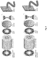
- shows a schematic diagram of optical fibres of comparative examples as well as optical fibres according to the invention. The nano-
inclusion 4 is in the form of: 4a) a rod made of the D1 dielectric having the refractive index higher than thecore 1, 4b) a metal rod arranged in the nanotube made of a dielectric with a different refractive index than the core, as per the invention; 4c) set of rods symmetrically arranged relative to thecore 1 of the optical fibre, made of a dielectric having the refractive index higher than thecore 1, or 4d) a set of rods made of a dielectric with a different refractive index than thecore 1, surrounding the metal rod, as per the invention; - Fig. 4
- shows a photograph of an optical fibre according to the invention taken with an electron microscope in which: a) diameters d2 of the nanorods of the inner ring are smaller than the diameters d1 of the
nanorods 3 of the outer ring of thephotonic cladding 2, b) diameters d2 of thenanorods 3 of the inner ring are bigger than the diameters d1 of the nanorods of the outer ring of thephotonic cladding 2, - Fig. 5
- shows an optical fibre according to the invention used in the scheme of the experimental setup used to measure its polarization properties,
- Fig. 6
- shows numerically calculated values for an optical fibre of a comparative example, as a function of the diameter dINC 2 of the nano-
inclusion 4 filled only with the D1 dielectric having the refractive index higher than the core 1 (using SF6 glass): a) the effective refractive index neff for individual modes and b) modal field area for individual modes, - Fig. 7
- shows numerically calculated modes of an optical fibre of a comparative example, with the nano-
inclusion 4 filling thecore 1, filled only with the D1 dielectric having the refractive index higher than the core 1 (using SF6 glass), having a diameter dINC 2 of 150 nm (see Example 1): a) strongly narrowed linearly polarised (vertically) fundamental mode with Gaussian intensity profile LP01(HE11), b) radial mode LP11(TM01), - Fig. 8
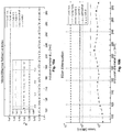
- shows numerically calculated parameters for an optical fibre according to the invention: a) the effective refractive index neff for individual modes and b) attenuation for individual modes, as a function of a diameter dINC 2 of the nano-
inclusion 4, comprising a silver rod in its central part, arranged in the D1 dielectric (SF6 glass), having the refractive index higher than the refractive index nCORE of thecore 1, - Fig. 9
- shows numerically calculated modes of an optical fibre according to the invention with the nano-
inclusion 4 filling thecore 1, comprising a silver rod having a diameter of DINC 1 50 nm arranged in the D1 dielectric (SF6 glass), having the refractive index higher than the refractive index nCORE of thecore 1 and a diameter dINC 2 of 150 nm: a) strongly suppressed linearly polarised (vertically) fundamental mode with Gaussian intensity profile LP01(HE11), b) radial mode LP11(TM01), - Fig. 10
- shows numerically calculated parameters for an optical fibre according to the invention: a) the effective refractive index for individual modes and b) attenuation for individual modes, as a diameter dINC 2 of the outer ring of the nano-
inclusion 4 made of the D2 dielectric (FK5 glass) having the refractive index lower than the refractive index nCORE of thecore 1, surrounding the central part of the nano-inclusion 4 comprising a silver rod, and - Fig. 11
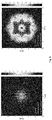
- shows an image of the mode captured by a CCD camera, having a radial polarisation with differently oriented linear polariser, for the radiation wavelength of 1550 nm for the optical fibre according to the invention.
- Dimensions of the optical fibres given in Examples 1-4 are merely illustrative and not limiting, without affecting the scope of the invention. The selection of a particular dielectric in the embodiments is merely exemplary and not limiting.
- The criterion for the selection of a particular glass is the difference in refractive index of the nano-inclusion dielectric and the optical fibre core and the thermal properties of such glass should be matched to the thermal properties of the optical fibre core, allowing for technical drawing of the optical fibre using the stack-and-draw technique. This condition is not met by just any set of glass.
- An optical fibre of a comparative example not covered by the appended claims, shown in
fig. 3 andfig. 4a , of a regular hexagonal structure has thephotonic cladding 2 surrounding thecore 1 arranged centrally in the optical fibre. Both thecore 1 and thephotonic cladding 2 are made of NC21A glass, being the basic glass. The properties of the optical fibre were examined using a radiation wavelength λ of 1.55 µm. Thephotonic cladding 2 is provided with nanorods with the diameters d1 and d2, made of FK5 glass. Therefore, the effective refractive index neff of thephotonic cladding 2, being an average refractive index of the NC21A basic glass and the FK5 glass is lower than the refractive index nCORE of thecore 1. - Alternatively, there are hollow nanoholes filled with air in the
photonic cladding 2, with the diameters d1 and d2, respectively. - Referring to
Fig. 4a , thenanorods 3 of thephotonic cladding 2 having a diameter d2 of 600 nm form the inner ring directly adjacent to thecore 1, and thenanorods 3 having a diameter d1 of 1200 nm form the outer ring of thephotonic cladding 2, which is adjacent to the inner ring formed of the capillaries d2. The diameter of thephotonic cladding 2 is 16 200 nm and the diameter dCORE of thecore 1 is 2400 nm. - The nano-
inclusion 4, in the form of a single rod (type of nano-inclusion 4a presented inFig. 3 ) is arranged inside thecore 1, in its geometrical centre. The rod is made only of the D1 electric, having the refractive index nD1 higher than the refractive index of the basic glass, i.e. the refractive index nCORE of thecore 1. The D1 dielectric is SF6 glass. The diameter DINC 2 of the nano-inclusion 4 is 150 nm. - The refractive index, with the radiation wavelength of 1.55 µm and for the applied dimensions of the optical fibre elements - for NC21A, FK5 and SF6 glass is: nNC21A = 1.5273; nFK5= 1.47293; nSF6 = 1.80518, respectively. The following condition is met: n01> nCORE>neff
- Alternatively, the nano-
inclusion 4 is a set of rods arranged symmetrically relative to thecore 1 made of NC21A glass, (type of nano-inclusion 4c shown inFig. 3 ) constructed entirely of the D1 dielectric of SF6 glass. The refractive index of the D1 dielectric is higher than the refractive index nRDZ of thecore 1 and the SF6 glass is thermally matched to the material of thecore 1. - The presented optical fibre transfers radial polarisation. At the same time the fundamental mode is partially discriminated (
Fig. 7 ). For this optical fibre, the modal field area of higher-order modes of cylindrical symmetry is comparable to the modal field area of the fundamental mode of conventional single-mode optical fibres. At the same time it is possible to obtain a lower attenuation for higher-order modes and higher birefringence than in conventional optical fibres. - The optical fibre of a regular hexagonal structure is constructed analogously to Example 1 of
photonic cladding 2 andcore 1 having a cross-section as shown inFig. 3 andFig. 4a . The properties of the optical fibre were examined using a radiation wavelength λ of 1.55 µm.Core 1 andphotonic cladding 2 are made of basic glass - NC21A. Thephotonic cladding 2 is provided with thenanoholes 3 filled with air, with the diameters d1 and d2, and the effective refractive index neff of thephotonic index 2 is lower than the refractive index nCORE of thecore 1. - The
nanorods 3 of thephotonic cladding 2 having a diameter d2 of 600 nm, form the inner ring directly adjacent to thecore 1, and thenanorods 3 having a diameter d1 of 1200 nm form the outer ring of thephotonic cladding 2, which is adjacent to the inner ring formed of the capillaries d2. The diameter of thephotonic cladding 2 is 16 200 nm and the diameter of thecore 1 is 2400 nm. - Inside the
core 1, in its geometrical centre, there is the nano-inclusion 4 in the form of a rod of metal alloy: Ag(56%), Cu(22%), Zn(17%), Sn(5%) (type of nano-inclusion 4b inFig. 3 ), arranged in a ring-shaped D2 dielectric having a diameter dINC 2. The D2 dielectric is a material thermally matching the material of thecore 1 and its refractive index nD2 is lower than the refractive index nCORE of thecore 1. The D2 dielectric is FK5 glass. The diameter dINC 1 of the nano-inclusion 4 metal rod is 50 nm, and the diameter dINC 2 of the nano-inclusion 4 is 150 nm. - The refractive index, with the radiation wavelength of 1.55 µm and for the applied dimensions of the optical fibre elements - for the glass NC21A, FK5 is:
- nNC21A = 1.5273 ; nFK5= 1.47293, respectively. The following condition is met: nD2< nCORE
- Alternatively, the nano-
inclusion 4 is a rod made of metal alloy: Ag(56%), Cu(22%), Zn(17%), Sn(5%) arranged in the ring-shaped D1 dielectric of SF6 glass. The material of thecore 1 is NC21A glass. The refractive index of the D1 dielectric, nSF6 = 1.80518 is higher than the refractive index of thecore 1. Material of the D1 dielectric is thermally matched to the material of thecore 1. - The optical fibre presented in the present embodiment transfers radial polarisation in all contemplated configurations. At the same time the fundamental mode is strongly discriminated due to the attenuation of metals (
Fig. 10 andFig. 8 ). - The impact of embedding inside the
core 1 the nano-inclusion 4, filled with the D1 dielectric having the structure shown inFig. 3 (type of nano-inclusion 4a and c) and discussed in Example 1, on the optical properties of the optical fibre according to the invention was compared with the existing solutions: - from the publication [1]: Birefringence and dispersion of cylindrically polarized modes in nanobore photonic crystal fiber T. G. Euser, M. A. Schmidt, N. Y. Joly, C. Gabriel, C. Marquardt, L. Y. Zang, M. Förtsch, P. Banzer, A. Brenn, D. Elser, M. Scharrer, G. Leuchs, and P. St.J. Russell, J. Opt. Soc. Am. B 28, 193-198 (2011)], wherein the nano-inclusion in the form of an air nanohole (air nano-inclusion) is arranged inside the optical fibre core and with an option of no nano-inclusion in the optical fibre core.
- In the solution from the publication [1] an air nano-inclusion in the form of an air nanohole is used in the optical fibre core.
Fig. 2 shows numerically calculated parameters for this optical fibre: the effective refractive index neff for individual modes (Fig. 2a ) and the area of the modal field (Fig. 2b ) as a function of a diameter of the nano-inclusion. Air nano-inclusion is characterized by a lower refractive index than the core. Although embedding the air nanohole inside the core causes the separation of individual modes, which increases with the diameter of the hole, increasing the diameter of the air nano-inclusion causes widening of the modal field area , especially of the fundamental modes, which is a negative phenomenon. - For the optical fibre according to Example 1 (
fig. 3 - type of nano-inclusion 4a and c) comprising the nano-inclusion 4, filled only with the D1 dielectric made of SF6 glass and with thephotonic cladding 2 andcore 1 made of NC21A basic glass, and where there is a relationship that nD1 > nCORE - graphically presented inFig. 6a and b, calculated: effective refractive index (fig. 6a ) and the area of the modal field (fig. 6b ), as a function of the diameter dINC 2 of the nano-inclusion 4. It turned out that the increase of the diameter dINC 2 of the nano-inclusion 4 filled only with SF6 glass causes birefringence, as high as in the case of air nano-inclusion of publication [1], however, the following relationship has unexpectedly been found in the case of using the nano-inclusion 4 made of SF6 glass: the increase of the diameter dINC 2 of the nano-inclusion 4 causes strong narrowing of the modal field area of the fundamental modes. It is a highly desirable effect because the narrowing of the modal field area significantly impedes the excitation of the fundamental mode. The operation of such optical fibre, with the nano-inclusion 4 filled with SF6 glass with the nano-inclusion diameter dINC 2 of 150 nm, is also confirmed by calculated mode field distributions shown inFig. 7 : of the fundamental mode (Fig. 7a ) and the radial mode (Fig. 7b ), respectively. - In the case of the photonic crystal fibre with a core without the inclusion, distributions of electric fields for individual modes are numerically calculated and are shown in
fig. 1 . All the modes of such an optical fibre are characterized by low attenuation. Comparing the optical fibre according to the invention with the photonic crystal fibre having a core without the inclusion, the modal field area of the fundamental mode HE11 of a new optical fibre is 2.5 times more narrow, while the modal field area of the radial mode is virtually unchanged. - The optical fibre with a structure presented in
Fig. 3 (type of nano-inclusion 4 a and c), discussed in Example 1, is more suitable for the propagation of radially polarised light beam than conventional optical fibres without the inclusion or whose inclusion is a hollow air nanohole in thephotonic cladding 2. Birefringence higher than in conventional optical fibres prevents random transfer of power between the modes and due to partial discrimination of the fundamental mode it is easier to couple radial polarised light with it. - The impact of embedding a dielectric nano-
inclusion 4 inside thecore 1, with a structure shown inFig. 3 (type of nano-inclusion 4 b and d), comprising a rod of metal alloy and discussed in Example 2 - on the optical properties of the optical fibre according to the invention was analysed, compared with the results obtained when embedding the nano-inclusion in the form of a silver rod having a diameter of 50 nm inside the core of the optical fibre, based on the disclosure of the optical fibre of publication [2]: An azimuthally polarizing photonic crystal fibre with a central gold nanowire P. Uebel, M. A. Schmidt, M. Scharrer and P. St. J. Russell, New J. Phys . 13 063016 (2011), which uses an analogous metal rod, but made of gold. According to the publication [2] a nano-inclusion in the form of a golden rod is used to discriminate the fundamental mode. - The results of the analysis of the optical fibre with a core comprising a nano-inclusion in the form of a silver rod, shown in Table 1 indicate that due to such nano-inclusion birefringence between the azimuthal and radial modes was achieved. Due to the attenuation, also the fundamental modes HE11 and hybrid modes HE21 were discriminated. Unfortunately, this solution also results in a significant increase in attenuation for radial and azimuthal modes, which disqualifies this solution in practical applications.
Table 1 shows a numerically calculated effective refractive index and attenuation for individual modes of a well-known optical fibre with a metallic nano-inclusion suggested in publication [2]. In the discussed option, the core comprises a silver nano-inclusion having a diameter of 50 nm: fundamental horizontal fundamental vertical hybrid 1 hybrid 2azimuthal radial neff 1.46855 1.46854 - 1.41234 1.41035 1.41031 attenuation [dB/m] 915 915 - 87 1.21 1.74 - In the case of the optical fibre according to the invention, discussed in Example 2 and with a structure shown in
Fig. 3b and d , two configurations are allowed: the first one, when the material D1 of a dielectric nanotube is characterized by the refractive index nD1 higher than the refractive index nCORE of thecore 1, and the second one, when the refractive index of the D2 dielectric material is lower than the refractive index nCORE of thecore 1. In the case of the results presented in the graphs ofFig. 8 andFig. 10 , which present the dependence of effective refractive index and attenuation for individual modes on the diameter dINC 2 of a dielectric nanotube surrounding a silver rod, the following materials are used:Fig. 8 presents a situation when a rod of the D1 dielectric is made of SF6 glass, with a higher refractive index than the refractive index nCORE of the core, andFig. 10 presents a situation when the rod of the D2 dielectric is made of FK5 glass, with a lower refractive index nD2 than the refractive index nCORE ofcore 1. In both cases, individual modes are separated from each other. Detailed figures regarding the effective refractive index and attenuation for the structure of the optical fibre according to the invention shown inFig. 3b and d described in Example 3 comprising the nano-inclusion 4 in the form of a silver rod having a diameter of dINC 1 = 50 nm in thecore 1, surrounded by a nanotube made of SF6 glass (D1 dielectric, keeping the relationship: nD1 > nCORE) or of FK5 glass (D2 dielectric, keeping the relationship: nD2 < nCORE) having a diameter dINC 2 of 150 nm - are shown in Table 2:fundamental horizontal fundamental vertical hybrid 1 hybrid 2azimuthal radial Ag rod dINC 1 = 50nm surrounded by a SF6 tube with a dINC 2 = 150nm; nD1 > nCORE neff 1.47062 1.47061 1.40972 1.41227 1.41030 1.41029 attenuation [dB/m] 347 347 1946 14 6.34 0.08 Ag rod dINC 1= 50nm surrounded by a FK tube dINC 2=150nm ; nD2 < nCORE neff 1.46830 1.46829 1.40907 1.41226 1.41029 1.41028 attenuation [dB/m] 202 202 2453 11 1.8 0.05 Fig. 7 for the inclusion with the refractive index higher than the refractive index of the core andFig. 9 for the inclusion with the refractive index lower than the refractive index of the core. They refer to: the fundamental mode (Fig. 7a andFig. 9a ) and the radial mode (Fig. 7b andFig. 9b ), respectively. Modes with radial polarisation are identical with the mode of the original optical fibre without the inclusion ofFig. 1f , however, the fundamental mode is strongly narrowed and attenuated. - The application of a dielectric-
metallic inclusion 4 in the optical fibre according to the invention, in contrast to purely metallic inclusion known from the publication [2] allowed to reduce the attenuation for the radial mode by two orders of magnitude. In other words, the proposed metallic-dielectric inclusions, in both options, made it possible to design the optical fibre that allows to transfer only radial polarisation (single-mode optical fibre). - The scheme of the experimental setup used for the characterisation of the optical properties of the optical fibre according to the invention is shown in
Fig. 5 . Radial polarisation beam is coupled to a photonic crystal fibre. The output beam is analysed by a rotating linear polariser. The intensity is recorded with a CCD camera. The experimental results are shown inFig. 11 . Both the image following the rotating polariser and its distinctive two-half-shape confirm maintaining the radial polarisation in the optical fibre. - The optical fibre of Example 1 was manufactured using the stack-and-draw technique. First, the structural preform was stacked, so that the material of NC21A glass, intended eventually for the
core 1, was centrally located, surrounded with the material intended for thephotonic cladding 2, i.e. with NC21A glass with dielectric inclusions (nanorodes 3) made of FK5 glass. The material of SF6 glass intended for the nano-inclusion 4 was placed inside thecore 1, in its geometrical centre. Thus prepared preform was repeatedly thinned at the tower for drawing optical fibres. The process of drawing was controlled by adjusting the temperature and the feeding speed of the preform and drawing of the fibre from the furnace.
Claims (12)
- A photonic crystal fibre for transferring a radially polarised light beam, having a core (1), preferably centrally located, and a photonic cladding (2) surrounding the core (1), wherein the photonic cladding (2) comprises nanoholes filled with air or nanorods (3), said fibre having the refractive index nCORE of the core (1) higher than the effective refractive index neff of the photonic cladding (2) and higher than the refractive index of the nanoholes or rods (3), and within the core (1), preferably at its geometrical centre, a nano-inclusion (4) is arranged, characterized in that the nano-inclusion (4) in the form of a metal rod arranged in a nanotube made of a dielectric or surrounded by a set of rods made of dielectric, wherein said dielectric has the refractive index nINC different from the refractive index nCORE of the core (1), and the said dielectric is glass, and preferably the material of the rod is selected from a group of metals comprising silver, gold, aluminium, copper, zinc, chromium, tin or an alloy of these metals, and wherein the nano-inclusion (4) introduces birefringence between the azimuthal and radial polarization modes and discriminates all the optical fibre modes except the radial polarisation mode.
- The fibre according to claim 1, wherein the dielectric is a D1 dielectric having the refractive index nD1 higher than the refractive index nCORE of the core (1).
- The fibre according to claim 1, wherein the dielectric is a D2 dielectric having the refractive index nD2 lower than the refractive index nCORE of the core (1).
- The fibre according to any one of the preceding claims 1 to 3, wherein the dielectric D1 or the dielectric D2 are selected from a group of exemplary glass: SF6, SF57, PBG-08, PBG-89, F2, FK5, NC21A, NC32, NC34, NC41, LLF1, PBS-57A, KB-03.
- The fibre according to any one of the preceding claims 1 to 4, wherein the core (1) is made of glass, for example NC21Aglass, or the photonic cladding (2) is made of glass, for example NC21A glass, or nanorods (3) are made of glass with the refractive index lower than the refractive index nCORE of the core (1), preferably selected from a group of exemplary glass: SF6, SF57, PBG-08, PBG-89, F2, FK5, NC21A, NC32, NC34, NC41, LLF1, PBS-57A, KB-03.
- The fibre according to any one of the preceding claims 1 to 5, wherein the photonic cladding (2) includes an inner ring of the nanorods or nanoholes (3) directly adjacent to the core (1) and having a diameter d2 and an outer ring of the nanorods or nanoholes (3) having a diameter d1, wherein preferably the diameter d2 is smaller than the diameter d1, wherein preferably, the diameter d2 is 600 nm and the diameter d1 is 1200 nm.
- The fibre according to any one of the preceding claims 1 to 6, wherein the nanorods or nanoholes (3) are arranged in the photonic cladding (2) in a hexagonal structure.
- The fibre according to any one of the preceding claims 1 to 7, wherein the fibre transfers radial polarisation across the entire cross-section of the beam.
- The fibre according to any one of the preceding claims 1 to 8, wherein the core (1) is located at the geometrical centre of the optical fibre.
- A method of manufacturing the fibre according to any one of the preceding claims 1 to 9, using the stack-and-draw technique comprising the steps of:- stacking materials for the fibre in structural preforms, so that the centrally located material for the core (1) is surrounded by a material for the photonic cladding (2), whereas in the material for the core (1) and preferably in its geometrical centre there is a material for the nano-inclusion (4), wherein the material for the nano-inclusion (4) contains a metal or a metal alloy surrounded by the dielectric having the refractive index nINC different from the refractive index nCORE of the core (1), and the said dielectric is made of glass, wherein it is preferred to use a metal selected from a group of metals comprising silver, gold, aluminium, copper, zinc, chromium, tin, or alloy of these metals,- thinning the preform into the form of an optical fibre at the tower for drawing optical fibres.
- The method according to claim 10 wherein a dielectric being the D1 dielectric is used, having the refractive index nD1 higher than the refractive index nCORE of the core (1) or a dielectric being the D2 dielectric is used, having the refractive index nD1 lower than the refractive index nCORE of the core (1).
- The method according to claim 10 or 11 wherein the dielectric D1 or the dielectric D2 are selected from the group of exemplary glass: SF6, SF57, PBG-08, PBG-89, F2, FK5, NC21A, NC32, NC34, NC41, LLF1, PBS-57A, KB-03.
Applications Claiming Priority (1)
| Application Number | Priority Date | Filing Date | Title |
|---|---|---|---|
| PL411696A PL226041B1 (en) | 2015-03-25 | 2015-03-25 | Photonic optical waveguide for transmitting radially polarized light beam and method for manufacturing such an optical waveguide |
Publications (2)
| Publication Number | Publication Date |
|---|---|
| EP3073300A1 EP3073300A1 (en) | 2016-09-28 |
| EP3073300B1 true EP3073300B1 (en) | 2018-05-02 |
Family
ID=54251918
Family Applications (1)
| Application Number | Title | Priority Date | Filing Date |
|---|---|---|---|
| EP15180047.1A Active EP3073300B1 (en) | 2015-03-25 | 2015-08-06 | A photonic crystal fibre for transferring radially polarised light beam and a method of manufacturing such a fibre |
Country Status (2)
| Country | Link |
|---|---|
| EP (1) | EP3073300B1 (en) |
| PL (1) | PL226041B1 (en) |
Families Citing this family (1)
| Publication number | Priority date | Publication date | Assignee | Title |
|---|---|---|---|---|
| CN110501776B (en) * | 2019-08-26 | 2021-03-12 | 燕山大学 | Single-mode single-polarization microstructure optical fiber |
Family Cites Families (4)
| Publication number | Priority date | Publication date | Assignee | Title |
|---|---|---|---|---|
| US7778498B2 (en) | 2008-02-12 | 2010-08-17 | Ofs Fitel Llc | Systems and techniques for generating cylindrical vector beams |
| US8111957B2 (en) | 2008-07-10 | 2012-02-07 | Corning Incorporated | +cylindrical polarization beams |
| CN101938080B (en) | 2010-06-25 | 2011-11-30 | 北京交通大学 | An active optical fiber with single-mode output TM01 mode characteristics |
| US20130177273A1 (en) | 2010-07-12 | 2013-07-11 | Research Foundation of CUNY on behalf of City College | Cylindrical Vector Beam Generation From A Multicore Optical Fiber |
-
2015
- 2015-03-25 PL PL411696A patent/PL226041B1/en unknown
- 2015-08-06 EP EP15180047.1A patent/EP3073300B1/en active Active
Non-Patent Citations (1)
| Title |
|---|
| None * |
Also Published As
| Publication number | Publication date |
|---|---|
| PL226041B1 (en) | 2017-06-30 |
| PL411696A1 (en) | 2016-09-26 |
| EP3073300A1 (en) | 2016-09-28 |
Similar Documents
| Publication | Publication Date | Title |
|---|---|---|
| US7155099B2 (en) | Holey optical fibres of non-silica based glass | |
| Mangan et al. | Experimental study of dual-core photonic crystal fibre | |
| US6968107B2 (en) | Holey optical fibres | |
| Pysz et al. | Stack and draw fabrication of soft glass microstructured fiber optics | |
| DE60217684T2 (en) | OPTICAL FIBERS WITH HIGH NUMERICAL APERTURE | |
| JP6121426B2 (en) | Microstructured optical fiber having a large core and a smoothed fundamental mode, its manufacturing method and its use in laser micromachining | |
| Zhang et al. | Design of large mode area all-solid anti-resonant fiber for high-power lasers | |
| TWI477833B (en) | Double fiber crystal fiber and its making method | |
| Fang et al. | Fabrication and characterization of glass‐ceramic fiber‐containing Cr3+‐doped ZnAl2O4 nanocrystals | |
| JP2017503189A (en) | Polarization and polarization maintaining leaky channel fiber | |
| WO2020210208A1 (en) | Infrared-transmitting, polarization-maintaining optical fiber and method for making | |
| CN104865635B (en) | A kind of ellipse covering polarization-maintaining large mode field gain fibre | |
| CN103880279B (en) | The preparation method of all solid state band gap-photonic crystal fiber of multicomponent glass | |
| Li et al. | Research on dual-wavelength single polarizing filter based on photonic crystal fiber | |
| Kristiansen et al. | Microstructured fibers and their applications | |
| EP3073300A1 (en) | A photonic crystal fibre for transferring radially polarised light beam and a method of manufacturing such a fibre | |
| Liu et al. | Tunable ultra-broadband polarization filter based on three-core resonance of the fluid-infiltrated and gold-coated photonic crystal fiber | |
| WO2018118807A1 (en) | Wavelength selective transfer of optical energy | |
| EP2165237B1 (en) | Photonic crystal electrooptic fiber and method for manufacturing such a fiber | |
| Zhang et al. | Highly efficient waveguided laser performance of diode pumped unclad Yb: YAG crystalline fibre | |
| Stepien et al. | Characterization of a large core photonic crystal fiber made of lead–bismuth–gallium oxide glass for broadband infrared transmission | |
| Pysz et al. | Multicomponent glass fiber optic integrated structures | |
| US6775450B2 (en) | Micro-structured optical fibers | |
| WO2004019092A1 (en) | Photonic crystal fibre | |
| EP1309890B1 (en) | Holey optical fibres, preforms and manufacturing methods |
Legal Events
| Date | Code | Title | Description |
|---|---|---|---|
| PUAI | Public reference made under article 153(3) epc to a published international application that has entered the european phase |
Free format text: ORIGINAL CODE: 0009012 |
|
| AK | Designated contracting states |
Kind code of ref document: A1 Designated state(s): AL AT BE BG CH CY CZ DE DK EE ES FI FR GB GR HR HU IE IS IT LI LT LU LV MC MK MT NL NO PL PT RO RS SE SI SK SM TR |
|
| AX | Request for extension of the european patent |
Extension state: BA ME |
|
| STAA | Information on the status of an ep patent application or granted ep patent |
Free format text: STATUS: REQUEST FOR EXAMINATION WAS MADE |
|
| RBV | Designated contracting states (corrected) |
Designated state(s): AL AT BE BG CH CY CZ DE DK EE ES FI FR GB GR HR HU IE IS IT LI LT LU LV MC MK MT NL NO PL PT RO RS SE SI SK SM TR |
|
| 17P | Request for examination filed |
Effective date: 20170327 |
|
| GRAP | Despatch of communication of intention to grant a patent |
Free format text: ORIGINAL CODE: EPIDOSNIGR1 |
|
| STAA | Information on the status of an ep patent application or granted ep patent |
Free format text: STATUS: GRANT OF PATENT IS INTENDED |
|
| INTG | Intention to grant announced |
Effective date: 20180208 |
|
| GRAS | Grant fee paid |
Free format text: ORIGINAL CODE: EPIDOSNIGR3 |
|
| GRAA | (expected) grant |
Free format text: ORIGINAL CODE: 0009210 |
|
| STAA | Information on the status of an ep patent application or granted ep patent |
Free format text: STATUS: THE PATENT HAS BEEN GRANTED |
|
| AK | Designated contracting states |
Kind code of ref document: B1 Designated state(s): AL AT BE BG CH CY CZ DE DK EE ES FI FR GB GR HR HU IE IS IT LI LT LU LV MC MK MT NL NO PL PT RO RS SE SI SK SM TR |
|
| REG | Reference to a national code |
Ref country code: GB Ref legal event code: FG4D |
|
| REG | Reference to a national code |
Ref country code: CH Ref legal event code: EP Ref country code: AT Ref legal event code: REF Ref document number: 995854 Country of ref document: AT Kind code of ref document: T Effective date: 20180515 |
|
| REG | Reference to a national code |
Ref country code: FR Ref legal event code: PLFP Year of fee payment: 4 |
|
| REG | Reference to a national code |
Ref country code: DE Ref legal event code: R096 Ref document number: 602015010608 Country of ref document: DE Ref country code: IE Ref legal event code: FG4D |
|
| REG | Reference to a national code |
Ref country code: NL Ref legal event code: MP Effective date: 20180502 |
|
| REG | Reference to a national code |
Ref country code: LT Ref legal event code: MG4D |
|
| PG25 | Lapsed in a contracting state [announced via postgrant information from national office to epo] |
Ref country code: BG Free format text: LAPSE BECAUSE OF FAILURE TO SUBMIT A TRANSLATION OF THE DESCRIPTION OR TO PAY THE FEE WITHIN THE PRESCRIBED TIME-LIMIT Effective date: 20180802 Ref country code: FI Free format text: LAPSE BECAUSE OF FAILURE TO SUBMIT A TRANSLATION OF THE DESCRIPTION OR TO PAY THE FEE WITHIN THE PRESCRIBED TIME-LIMIT Effective date: 20180502 Ref country code: NO Free format text: LAPSE BECAUSE OF FAILURE TO SUBMIT A TRANSLATION OF THE DESCRIPTION OR TO PAY THE FEE WITHIN THE PRESCRIBED TIME-LIMIT Effective date: 20180802 Ref country code: LT Free format text: LAPSE BECAUSE OF FAILURE TO SUBMIT A TRANSLATION OF THE DESCRIPTION OR TO PAY THE FEE WITHIN THE PRESCRIBED TIME-LIMIT Effective date: 20180502 Ref country code: SE Free format text: LAPSE BECAUSE OF FAILURE TO SUBMIT A TRANSLATION OF THE DESCRIPTION OR TO PAY THE FEE WITHIN THE PRESCRIBED TIME-LIMIT Effective date: 20180502 Ref country code: ES Free format text: LAPSE BECAUSE OF FAILURE TO SUBMIT A TRANSLATION OF THE DESCRIPTION OR TO PAY THE FEE WITHIN THE PRESCRIBED TIME-LIMIT Effective date: 20180502 |
|
| PG25 | Lapsed in a contracting state [announced via postgrant information from national office to epo] |
Ref country code: NL Free format text: LAPSE BECAUSE OF FAILURE TO SUBMIT A TRANSLATION OF THE DESCRIPTION OR TO PAY THE FEE WITHIN THE PRESCRIBED TIME-LIMIT Effective date: 20180502 Ref country code: RS Free format text: LAPSE BECAUSE OF FAILURE TO SUBMIT A TRANSLATION OF THE DESCRIPTION OR TO PAY THE FEE WITHIN THE PRESCRIBED TIME-LIMIT Effective date: 20180502 Ref country code: LV Free format text: LAPSE BECAUSE OF FAILURE TO SUBMIT A TRANSLATION OF THE DESCRIPTION OR TO PAY THE FEE WITHIN THE PRESCRIBED TIME-LIMIT Effective date: 20180502 Ref country code: GR Free format text: LAPSE BECAUSE OF FAILURE TO SUBMIT A TRANSLATION OF THE DESCRIPTION OR TO PAY THE FEE WITHIN THE PRESCRIBED TIME-LIMIT Effective date: 20180803 Ref country code: HR Free format text: LAPSE BECAUSE OF FAILURE TO SUBMIT A TRANSLATION OF THE DESCRIPTION OR TO PAY THE FEE WITHIN THE PRESCRIBED TIME-LIMIT Effective date: 20180502 |
|
| REG | Reference to a national code |
Ref country code: AT Ref legal event code: MK05 Ref document number: 995854 Country of ref document: AT Kind code of ref document: T Effective date: 20180502 |
|
| PG25 | Lapsed in a contracting state [announced via postgrant information from national office to epo] |
Ref country code: PL Free format text: LAPSE BECAUSE OF FAILURE TO SUBMIT A TRANSLATION OF THE DESCRIPTION OR TO PAY THE FEE WITHIN THE PRESCRIBED TIME-LIMIT Effective date: 20180502 Ref country code: EE Free format text: LAPSE BECAUSE OF FAILURE TO SUBMIT A TRANSLATION OF THE DESCRIPTION OR TO PAY THE FEE WITHIN THE PRESCRIBED TIME-LIMIT Effective date: 20180502 Ref country code: AT Free format text: LAPSE BECAUSE OF FAILURE TO SUBMIT A TRANSLATION OF THE DESCRIPTION OR TO PAY THE FEE WITHIN THE PRESCRIBED TIME-LIMIT Effective date: 20180502 Ref country code: DK Free format text: LAPSE BECAUSE OF FAILURE TO SUBMIT A TRANSLATION OF THE DESCRIPTION OR TO PAY THE FEE WITHIN THE PRESCRIBED TIME-LIMIT Effective date: 20180502 Ref country code: SK Free format text: LAPSE BECAUSE OF FAILURE TO SUBMIT A TRANSLATION OF THE DESCRIPTION OR TO PAY THE FEE WITHIN THE PRESCRIBED TIME-LIMIT Effective date: 20180502 Ref country code: RO Free format text: LAPSE BECAUSE OF FAILURE TO SUBMIT A TRANSLATION OF THE DESCRIPTION OR TO PAY THE FEE WITHIN THE PRESCRIBED TIME-LIMIT Effective date: 20180502 Ref country code: CZ Free format text: LAPSE BECAUSE OF FAILURE TO SUBMIT A TRANSLATION OF THE DESCRIPTION OR TO PAY THE FEE WITHIN THE PRESCRIBED TIME-LIMIT Effective date: 20180502 |
|
| REG | Reference to a national code |
Ref country code: DE Ref legal event code: R097 Ref document number: 602015010608 Country of ref document: DE |
|
| PG25 | Lapsed in a contracting state [announced via postgrant information from national office to epo] |
Ref country code: SM Free format text: LAPSE BECAUSE OF FAILURE TO SUBMIT A TRANSLATION OF THE DESCRIPTION OR TO PAY THE FEE WITHIN THE PRESCRIBED TIME-LIMIT Effective date: 20180502 Ref country code: IT Free format text: LAPSE BECAUSE OF FAILURE TO SUBMIT A TRANSLATION OF THE DESCRIPTION OR TO PAY THE FEE WITHIN THE PRESCRIBED TIME-LIMIT Effective date: 20180502 |
|
| PLBE | No opposition filed within time limit |
Free format text: ORIGINAL CODE: 0009261 |
|
| STAA | Information on the status of an ep patent application or granted ep patent |
Free format text: STATUS: NO OPPOSITION FILED WITHIN TIME LIMIT |
|
| PG25 | Lapsed in a contracting state [announced via postgrant information from national office to epo] |
Ref country code: MC Free format text: LAPSE BECAUSE OF FAILURE TO SUBMIT A TRANSLATION OF THE DESCRIPTION OR TO PAY THE FEE WITHIN THE PRESCRIBED TIME-LIMIT Effective date: 20180502 |
|
| REG | Reference to a national code |
Ref country code: CH Ref legal event code: PL |
|
| 26N | No opposition filed |
Effective date: 20190205 |
|
| PG25 | Lapsed in a contracting state [announced via postgrant information from national office to epo] |
Ref country code: CH Free format text: LAPSE BECAUSE OF NON-PAYMENT OF DUE FEES Effective date: 20180831 Ref country code: LU Free format text: LAPSE BECAUSE OF NON-PAYMENT OF DUE FEES Effective date: 20180806 Ref country code: LI Free format text: LAPSE BECAUSE OF NON-PAYMENT OF DUE FEES Effective date: 20180831 |
|
| REG | Reference to a national code |
Ref country code: BE Ref legal event code: MM Effective date: 20180831 |
|
| REG | Reference to a national code |
Ref country code: IE Ref legal event code: MM4A |
|
| PG25 | Lapsed in a contracting state [announced via postgrant information from national office to epo] |
Ref country code: SI Free format text: LAPSE BECAUSE OF FAILURE TO SUBMIT A TRANSLATION OF THE DESCRIPTION OR TO PAY THE FEE WITHIN THE PRESCRIBED TIME-LIMIT Effective date: 20180502 |
|
| PG25 | Lapsed in a contracting state [announced via postgrant information from national office to epo] |
Ref country code: IE Free format text: LAPSE BECAUSE OF NON-PAYMENT OF DUE FEES Effective date: 20180806 |
|
| PG25 | Lapsed in a contracting state [announced via postgrant information from national office to epo] |
Ref country code: BE Free format text: LAPSE BECAUSE OF NON-PAYMENT OF DUE FEES Effective date: 20180831 |
|
| PG25 | Lapsed in a contracting state [announced via postgrant information from national office to epo] |
Ref country code: AL Free format text: LAPSE BECAUSE OF FAILURE TO SUBMIT A TRANSLATION OF THE DESCRIPTION OR TO PAY THE FEE WITHIN THE PRESCRIBED TIME-LIMIT Effective date: 20180502 |
|
| PG25 | Lapsed in a contracting state [announced via postgrant information from national office to epo] |
Ref country code: MT Free format text: LAPSE BECAUSE OF NON-PAYMENT OF DUE FEES Effective date: 20180806 |
|
| PG25 | Lapsed in a contracting state [announced via postgrant information from national office to epo] |
Ref country code: TR Free format text: LAPSE BECAUSE OF FAILURE TO SUBMIT A TRANSLATION OF THE DESCRIPTION OR TO PAY THE FEE WITHIN THE PRESCRIBED TIME-LIMIT Effective date: 20180502 |
|
| PG25 | Lapsed in a contracting state [announced via postgrant information from national office to epo] |
Ref country code: PT Free format text: LAPSE BECAUSE OF FAILURE TO SUBMIT A TRANSLATION OF THE DESCRIPTION OR TO PAY THE FEE WITHIN THE PRESCRIBED TIME-LIMIT Effective date: 20180502 |
|
| PG25 | Lapsed in a contracting state [announced via postgrant information from national office to epo] |
Ref country code: HU Free format text: LAPSE BECAUSE OF FAILURE TO SUBMIT A TRANSLATION OF THE DESCRIPTION OR TO PAY THE FEE WITHIN THE PRESCRIBED TIME-LIMIT; INVALID AB INITIO Effective date: 20150806 Ref country code: CY Free format text: LAPSE BECAUSE OF FAILURE TO SUBMIT A TRANSLATION OF THE DESCRIPTION OR TO PAY THE FEE WITHIN THE PRESCRIBED TIME-LIMIT Effective date: 20180502 Ref country code: MK Free format text: LAPSE BECAUSE OF NON-PAYMENT OF DUE FEES Effective date: 20180502 |
|
| PG25 | Lapsed in a contracting state [announced via postgrant information from national office to epo] |
Ref country code: IS Free format text: LAPSE BECAUSE OF FAILURE TO SUBMIT A TRANSLATION OF THE DESCRIPTION OR TO PAY THE FEE WITHIN THE PRESCRIBED TIME-LIMIT Effective date: 20180902 |
|
| PGFP | Annual fee paid to national office [announced via postgrant information from national office to epo] |
Ref country code: DE Payment date: 20250828 Year of fee payment: 11 |
|
| PGFP | Annual fee paid to national office [announced via postgrant information from national office to epo] |
Ref country code: GB Payment date: 20250828 Year of fee payment: 11 |
|
| PGFP | Annual fee paid to national office [announced via postgrant information from national office to epo] |
Ref country code: FR Payment date: 20250828 Year of fee payment: 11 |