EP3073241A1 - Analyse de la couche limite d'une pale de rotor - Google Patents
Analyse de la couche limite d'une pale de rotor Download PDFInfo
- Publication number
- EP3073241A1 EP3073241A1 EP14195427.1A EP14195427A EP3073241A1 EP 3073241 A1 EP3073241 A1 EP 3073241A1 EP 14195427 A EP14195427 A EP 14195427A EP 3073241 A1 EP3073241 A1 EP 3073241A1
- Authority
- EP
- European Patent Office
- Prior art keywords
- rotor blade
- pressure sensing
- sensing unit
- pressure
- boundary layer
- Prior art date
- Legal status (The legal status is an assumption and is not a legal conclusion. Google has not performed a legal analysis and makes no representation as to the accuracy of the status listed.)
- Withdrawn
Links
Images


Classifications
-
- G—PHYSICS
- G01—MEASURING; TESTING
- G01M—TESTING STATIC OR DYNAMIC BALANCE OF MACHINES OR STRUCTURES; TESTING OF STRUCTURES OR APPARATUS, NOT OTHERWISE PROVIDED FOR
- G01M9/00—Aerodynamic testing; Arrangements in or on wind tunnels
- G01M9/06—Measuring arrangements specially adapted for aerodynamic testing
-
- F—MECHANICAL ENGINEERING; LIGHTING; HEATING; WEAPONS; BLASTING
- F03—MACHINES OR ENGINES FOR LIQUIDS; WIND, SPRING, OR WEIGHT MOTORS; PRODUCING MECHANICAL POWER OR A REACTIVE PROPULSIVE THRUST, NOT OTHERWISE PROVIDED FOR
- F03D—WIND MOTORS
- F03D13/00—Assembly, mounting or commissioning of wind motors; Arrangements specially adapted for transporting wind motor components
- F03D13/30—Commissioning, e.g. inspection, testing or final adjustment before releasing for production
-
- F—MECHANICAL ENGINEERING; LIGHTING; HEATING; WEAPONS; BLASTING
- F03—MACHINES OR ENGINES FOR LIQUIDS; WIND, SPRING, OR WEIGHT MOTORS; PRODUCING MECHANICAL POWER OR A REACTIVE PROPULSIVE THRUST, NOT OTHERWISE PROVIDED FOR
- F03D—WIND MOTORS
- F03D17/00—Monitoring or testing of wind motors, e.g. diagnostics
-
- G—PHYSICS
- G01—MEASURING; TESTING
- G01M—TESTING STATIC OR DYNAMIC BALANCE OF MACHINES OR STRUCTURES; TESTING OF STRUCTURES OR APPARATUS, NOT OTHERWISE PROVIDED FOR
- G01M5/00—Investigating the elasticity of structures, e.g. deflection of bridges or air-craft wings
- G01M5/0016—Investigating the elasticity of structures, e.g. deflection of bridges or air-craft wings of aircraft wings or blades
-
- F—MECHANICAL ENGINEERING; LIGHTING; HEATING; WEAPONS; BLASTING
- F05—INDEXING SCHEMES RELATING TO ENGINES OR PUMPS IN VARIOUS SUBCLASSES OF CLASSES F01-F04
- F05B—INDEXING SCHEME RELATING TO WIND, SPRING, WEIGHT, INERTIA OR LIKE MOTORS, TO MACHINES OR ENGINES FOR LIQUIDS COVERED BY SUBCLASSES F03B, F03D AND F03G
- F05B2270/00—Control
- F05B2270/30—Control parameters, e.g. input parameters
- F05B2270/301—Pressure
- F05B2270/3015—Pressure differential
-
- F—MECHANICAL ENGINEERING; LIGHTING; HEATING; WEAPONS; BLASTING
- F05—INDEXING SCHEMES RELATING TO ENGINES OR PUMPS IN VARIOUS SUBCLASSES OF CLASSES F01-F04
- F05B—INDEXING SCHEME RELATING TO WIND, SPRING, WEIGHT, INERTIA OR LIKE MOTORS, TO MACHINES OR ENGINES FOR LIQUIDS COVERED BY SUBCLASSES F03B, F03D AND F03G
- F05B2270/00—Control
- F05B2270/30—Control parameters, e.g. input parameters
- F05B2270/324—Air pressure
-
- Y—GENERAL TAGGING OF NEW TECHNOLOGICAL DEVELOPMENTS; GENERAL TAGGING OF CROSS-SECTIONAL TECHNOLOGIES SPANNING OVER SEVERAL SECTIONS OF THE IPC; TECHNICAL SUBJECTS COVERED BY FORMER USPC CROSS-REFERENCE ART COLLECTIONS [XRACs] AND DIGESTS
- Y02—TECHNOLOGIES OR APPLICATIONS FOR MITIGATION OR ADAPTATION AGAINST CLIMATE CHANGE
- Y02E—REDUCTION OF GREENHOUSE GAS [GHG] EMISSIONS, RELATED TO ENERGY GENERATION, TRANSMISSION OR DISTRIBUTION
- Y02E10/00—Energy generation through renewable energy sources
- Y02E10/70—Wind energy
- Y02E10/72—Wind turbines with rotation axis in wind direction
Definitions
- the present invention relates to an arrangement for analyzing the boundary layer of a rotor blade for a wind turbine.
- the invention is furthermore related to a method of analyzing the boundary layer of a rotor blade for a wind turbine and to the use of such a method for determining whether the boundary layer of the rotor blade is separated at a predetermined chordwise position of the rotor blade.
- the object of the present invention is to provide means for characterizing the boundary layer of a rotor blade for a wind turbine.
- an arrangement for analyzing the boundary layer of a rotor blade for a wind turbine comprising a first pressure sensing unit located at a trailing edge section of the rotor blade, a second pressure sensing unit located upstream of the first pressure sensing unit, and a device for determining the differential pressure between the first pressure sensing unit and the second pressure sensing unit.
- the arrangement comprises an evaluation unit, which is connected with the device, and which is arranged and prepared for comparing the determined differential pressure with a reference differential pressure, such that the boundary layer of the rotor blade is characterized by the evaluation unit.
- Such an arrangement has numerous advantages for the operation of a wind turbine. In principle, avoiding boundary layer separation leads to a better performance of the wind turbine and may consequently also lead to a better performance of the wind farm comprising the wind turbine.
- a first advantage is that routine detection of stall events, i.e. detection of a flow separation of the boundary layer, could be used by a controller to correct or report the issue.
- the operation of the wind turbine could adaptively be curtailed if low noise operation is desired.
- Another advantage of the described arrangement is that blade soiling could be detected since separation of the boundary layer is commonly more frequent when rotor blades are soiled compared to clean rotor blades.
- Yet another advantage is the possibility of detection of extreme wind shear or yaw error.
- wind turbine can be adaptively operated more aggressively in order to increase the energy production of the wind turbine.
- wind turbines are commonly controlled in a conservative manner in order to ensure that the rotor blades are unlikely to encounter boundary layer separation under normal operating conditions.
- a wind turbine with the described arrangement has, for instance, the advantage that the pitch angle can be chosen differently such that the rotor blade can be operated more aggressively.
- the differential pressure can be determined by measuring a first pressure by the first pressure sensing unit, measuring the second pressure by the second pressure sensing unit and subtracting the first pressure by the second pressure or vice versa. In other words, an absolute value for the first pressure is determined, an absolute value for the second pressure is determined, and subsequently both measured pressures are used to calculate the difference.
- the differential pressure between the first pressure sensing unit and the second pressure sensing unit may directly be measured. This has the advantage that the accuracy, i.e. the measurement error, is reduced.
- the pressure sensing units comprise so called pressure taps, i.e. holes through the surface of the rotor blade and exposed to the outside air.
- Pressure taps are inexpensive and have exemplarily a diameter in the range of one millimeter.
- the device for determining the differential pressure between the two pressure sensing units i.e. the pressure taps, may be a simple, small and low-cost device which is referred to as a differential pressure transducer.
- the pressure transducer and/or the pressure sensing units may require protection against overpressure damage. Such damage may occur if pneumatic purging is applied to the pressure transducer and/or the pressure sensing units in order to clear pressure line blockages. Such blockages may occur if dirt, water or other small particles block any portion of the pressure transducer and/or the pressure sensing units.
- a key advantage of the present invention is that noise can be detected and prevented at an early stage by a simple and reliable manner. This relates to the fact that elevated noise levels are often related to boundary layer flow separation. Another consequence of boundary layer separation is commonly a reduction of the power production by the wind turbine. Thus, additionally, the electrical performance can be enhanced by the inventive arrangement.
- the first pressure sensing unit is located at a chordwise position between 90 per cent of the chord length and 100 per cent of the chord length, as measured from the leading edge of the rotor blade.
- the section of the rotor blade between 90 per cent of the chord length and 100 per cent of the chord length is referred to as the trailing edge section of the rotor blade.
- the difficulty with installing the first pressure unit close to the trailing edge is due to the fact that possibly the cavity inside the shell that surrounds the rotor blade is small or even non-existent at chordwise positions aft of 90 per cent.
- a placement of the first pressure sensing unit right at the trailing edge i.e. at a chordwise position of 100 per cent as measured from the leading edge of the rotor blade, might be realized by integrating the first pressure sensing unit directly into the trailing edge.
- the second pressure sensing unit is located separately from the first pressure sensing unit upstream of the first pressure sensing unit by a chordwise distance between 5 per cent of the chord length and 50 per cent of the chord length.
- the second pressure sensing unit is located upstream of the first pressure sensing unit by a chordwise distance between 20 per cent of the chord length and 40 per cent of the chord length.
- chordwise positions for both pressure sensing units are advantageously chosen such that a meaningful and reliable differential pressure between the two pressure sensing units can be determined.
- a placement of the first pressure sensing unit at 90 per cent of the chord length and a placement of the second pressure sensing unit at 70 per cent of the chord length has been proven to be well-suited for many of the typical industrial rotor blade shapes.
- the optimum position depends on the airfoil shape of the rotor blade and other factors such as the typical operating conditions of the rotor blade.
- first pressure sensing unit and/or the second pressure sensing unit are located on the suction side of the rotor blade.
- both an arrangement located at the pressure side of the rotor blade and an arrangement located at the suction side of the rotor blade could be advantageous.
- the airfoil has a symmetric shape - in other words, the pressure side has an identical curvature from the leading edge to the trailing edge as the suction side - a placement of the arrangement on either side or even on both sides seems possible.
- most rotor blades are particularly sensitive regarding flow separation of the boundary layer at the suction side.
- first pressure sensing unit and/or the second pressure sensing unit are integrated in the shell of the rotor blade.
- Integrating the pressure sensing units into the shell of the rotor blades comprises manufacturing a through hole through the entire shell.
- pressure sensing units with a small diameter of a few millimeters or even less than one millimeter can be chosen, these through holes have a minor impact on the structure and the aerodynamics of the rotor blade.
- the through holes for integration of the pressure sensing units into the shell may be milled into the shell after manufacturing of the rotor blade.
- the device for measuring the differential pressure between the first pressure sensing unit and the second pressure sensing unit is located inside the cavity which is delimited by the shells of the rotor blade.
- the cavity has to be understood as a hollow space inside the rotor blade surrounded by the blade shells. Due to reasons of aerodynamics and structure, the device for measuring the differential pressure is advantageously inside the cavity and attached to the inner shell of the rotor blade. Attachment may be carried out by an adhesive or by bolts or by screws or other suitable means.
- a plurality of first pressure sensing units and second pressure sensing units are arranged in the spanwise direction of the rotor blade.
- the invention is also directed towards a method of analyzing the boundary layer of a rotor blade for a wind turbine comprising the following steps:
- the method further comprises optimizing the adjustment of the pitch angle of the rotor blade such that the performance of the rotor blade is optimized.
- the rotor blade and the wind turbine as a whole can be operated more aggressively, thus the annual energy production is increased. This increase is possible due to a more detailed and more comprehensive understanding of flow separation along the rotor blade.
- the method further comprises the step of determining a measured pressure gradient based on a determined differential pressure and comparing the determined pressure gradient with a reference pressure gradient.
- the invention is also related to the use of a method for determining whether the boundary layer of the rotor blade is separated at a predetermined chordwise position of the rotor blade. This is achieved by comparison of the determined differential pressure with a reference differential pressure by means of an evaluation unit.
- the described arrangement, method and/or use is advantageous. This is due to the fact that for industrial applications characterization of the boundary layer at airfoil test samples is not sufficient. It is advantageous that the boundary layer is characterized and evaluated continuously such that operation of the wind turbine can frequently be changed or modified. Thus, having a plurality of pressure sensing units placed or distributed across the surface of the rotor blade is a significant advantage compared to state of the art rotor blades.
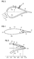
- a wind turbine 10 is shown.
- the wind turbine 10 comprises a nacelle 12 and a tower 11.
- the nacelle 12 is mounted at the top of the tower 11.
- the nacelle 12 is mounted rotatable with regard to the tower 11 by means of a yaw bearing.
- the axis of rotation of the nacelle 12 with regard to the tower 11 is referred to as the yaw axis.
- the wind turbine 10 also comprises a hub 13 with three rotor blades 20 (of which two rotor blades 20 are depicted in Figure 1 ).
- the hub 13 is mounted rotatable with regard to the nacelle 12 by means of a main bearing.
- the hub 13 is mounted rotatable about a rotor axis of rotation 14.
- the wind turbine 10 furthermore comprises a main shaft, which connects the hub 13 with a rotor of a generator 15.
- the hub 13 is connected directly to the rotor, thus the wind turbine 10 is referred to as a gearless, direct driven wind turbine.
- the hub 13 may also be connected to the rotor via a gearbox. This type of wind turbine is referred to as a geared wind turbine.
- the generator 15 is accommodated within the nacelle 12. It comprises the rotor and a stator. The generator 15 is arranged and prepared for converting the rotational energy from the rotor into electrical energy.
- the rotor blade 20 comprises a pitch axis 16 about which the rotor blade 20 can be rotated.
- FIG. 2 shows a rotor blade 20 of a wind turbine.
- the rotor blade 20 comprises a root section 21 with a root 211 and a tip section 22 with a tip 221.
- the root 211 and the tip 221 are virtually connected by the span 26 which follows the shape of the rotor blade 20. If the rotor blade were a rectangular shaped object, the span 26 would be a straight line. However, as the rotor blade 20 features a varying thickness, the span 26 is slightly curved or bent as well. Note that if the rotor blade 20 was bent itself, then the span 26 would be bent, too.
- the rotor blade 20 furthermore comprises a leading edge section 24 with a leading edge 241 and a trailing edge section 23 with a trailing edge 231.
- the trailing edge section 23 surrounds the trailing edge 231.
- the leading edge section 24 surrounds the leading edge 241.
- chord line 27 which connects the leading edge 241 with the trailing edge 231 can be defined. Note that the chord line 27 is perpendicular to the span 26.
- the shoulder 28 is defined in the region where the chord line comprises a maximum chord length.
- the rotor blade 20 can be divided into an inboard section which comprises the half of the rotor blade 20 adjacent to the root section 21 and an outboard section which comprises the half of the rotor blade 20 which is adjacent to the tip section 22.
- Figure 3 visualizes the boundary layer 30 of the rotor blade.
- the chord line 27 is a straight line connecting the leading edge 241 and the trailing edge 231. It also divides the surface of the rotor blade 20 into an upper section which is referred to as the suction side 251 and a lower section which is referred to as the pressure side 252.
- An airflow 32 impinges on the rotor blade 20 at the leading edge section 24 of the rotor blade 20.
- the chord line 27 and the direction of the airflow 32 may comprise an angle, which is commonly referred to as the angle of attack and which typically comprises a few degrees up to twenty or thirty degrees.
- the velocity of the airflow 32 approaches zero if measured directly in close proximity to the surface. In a direction perpendicular to the surface the velocity of the airflow increases. If the velocity of the airflow reaches a value of exemplarily 95 per cent of the free stream velocity, the socalled limit of the boundary layer 30 is reached.
- the thickness of the boundary layer 31 is defined by the distance away of the surface of the rotor blade at which 99 per cent of the free stream velocity is reached.
- the thickness of the boundary layer 31 is in a range between a few millimeters and a few centimeters, for example up to 5 centimeters.
- the thickness of the boundary layer 31 is not equal along the entire cross section of the rotor blade.
- the boundary layer 30 is attached at the entire rotor blade from the leading edge 241 to the trailing edge 231. Under different conditions the boundary layer is detached at a certain chordwise position of, for instance, eighty per cent as measured from the leading edge 241.
- Figure 4 shows an arrangement for analyzing the boundary layer.
- the arrangement comprises a first pressure sensing unit 41 and a second pressure sensing unit 42. These two pressure sensing units 41, 42 are connected to a device 43 which is arranged and prepared for determining the differential pressure at the given chordwise positions.
- the first pressure sensing unit 41 is located at the trailing edge, in other words at one hundred per cent chordwise position as measured from the leading edge 24.
- the second pressure sensing unit 42 is located upstream of the first pressure sensing unit 41. In other words, the second pressure sensing unit 42 is located at a different chordwise position compared to the first pressure sensing unit 41.
- the spanwise position of both pressure sensing units 41, 42 is substantially equal.
- Figure 5 shows a detailed view of the trailing edge section of the rotor blade.
- the blade shell 29 can be seen.
- two through holes through the shell 29 are provided.
- the first pressure sensing unit 41 is integrated in the first through hole while the second pressure sensing unit 42 is integrated in the second through hole.
- the spanwise position of both pressure sensing units 41, 42 is substantially equal.
- the chordwise position of the first pressure sensing unit 41 is approximately ninety-two per cent.
- the chordwise position of the second pressure sensing unit 42 is approximately sixty-six per cent.
- Both pressure sensing units 41, 42 are connected by a device 43 for determining the differential pressure.
- the device 43 is attached to the inner surface of the shell 29.
- the device 43 is furthermore connected with an evaluation unit 44.
- the evaluation unit 44 is capable to compare the determined differential pressure with a reference differential pressure.
- the boundary layer 30 of the rotor blade 20 can be characterized.
- p ⁇ signifies the ambient air pressure
- T ⁇ signifies the ambient air temperature
- R air signifies the universal gas constant for air
- ⁇ rotor signifies the rotational rate of the rotor
- r port signifies the radial distance from the rotor center to the pressure sensing unit
- r tip signifies the rotor radius
- ⁇ signifies the tip speed ratio.
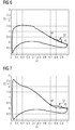
- FIGS. 6 and 7 each illustrate the normalized pressure differential 52 in dependence of the chordwise position 51.
- Figure 6 shows the normalized pressure differential 52 for a rotor blade with an attached boundary layer.
- the normalized pressure as measured by the second pressure sensing unit 42 is considerably lower than the pressure measured by the first pressure sensing unit 41.
- the pressure gradient 53 that is determined is relatively large.
- Figure 7 shows the same airfoil as in Figure 6 .
- boundary layer separation occurs such that the pressure gradient 53 which is determined by comparison of the normalized pressure at the second pressure sensing unit 42 and the first pressure sensing unit 41 is small.
Priority Applications (1)
| Application Number | Priority Date | Filing Date | Title |
|---|---|---|---|
| EP14195427.1A EP3073241A1 (fr) | 2014-11-28 | 2014-11-28 | Analyse de la couche limite d'une pale de rotor |
Applications Claiming Priority (1)
| Application Number | Priority Date | Filing Date | Title |
|---|---|---|---|
| EP14195427.1A EP3073241A1 (fr) | 2014-11-28 | 2014-11-28 | Analyse de la couche limite d'une pale de rotor |
Publications (1)
| Publication Number | Publication Date |
|---|---|
| EP3073241A1 true EP3073241A1 (fr) | 2016-09-28 |
Family
ID=51987071
Family Applications (1)
| Application Number | Title | Priority Date | Filing Date |
|---|---|---|---|
| EP14195427.1A Withdrawn EP3073241A1 (fr) | 2014-11-28 | 2014-11-28 | Analyse de la couche limite d'une pale de rotor |
Country Status (1)
| Country | Link |
|---|---|
| EP (1) | EP3073241A1 (fr) |
Cited By (1)
| Publication number | Priority date | Publication date | Assignee | Title |
|---|---|---|---|---|
| WO2018149533A1 (fr) * | 2017-02-20 | 2018-08-23 | Siemens Wind Power A/S | Système et procédé pour déterminer l'état de salissure d'une pale de rotor d'éolienne |
Citations (8)
| Publication number | Priority date | Publication date | Assignee | Title |
|---|---|---|---|---|
| DE3106624A1 (de) * | 1981-02-23 | 1982-09-16 | Dietrich, Reinhard, 8037 Olching | Regelungsverfahren fuer windenergieanlagen mit direkt aus der umstroemung des aerodynamisch wirksamen und auftrieberzeugenden profiles gewonnenen eingangssignalen |
| EP2133562A2 (fr) * | 2008-06-13 | 2009-12-16 | General Electric Company | Procédé et appareil de mesure de la condition de débit d'air sur la pale d'une éolienne |
| US20100076614A1 (en) * | 2009-11-05 | 2010-03-25 | Jacob Johannes Nies | Systems and method for operating a wind turbine having active flow control |
| US20100101328A1 (en) * | 2008-10-23 | 2010-04-29 | Peder Bay Enevoldsen | Stall detection by use of pressure sensors |
| US20100266405A1 (en) * | 2009-04-16 | 2010-10-21 | Frontier Wind, Llc | Pressure Based Load Measurement |
| US20110206507A1 (en) * | 2011-01-04 | 2011-08-25 | Shailesh Singh Bhaisora | System and method of manipulating a boundary layer across a rotor blade of a wind turbine |
| US20120024071A1 (en) * | 2011-05-03 | 2012-02-02 | Herrig Andreas | Device and method for measuring pressure on wind turbine components |
| WO2012122669A1 (fr) * | 2011-03-14 | 2012-09-20 | General Electric Company | Pales de turbine éolienne ayant des capteurs de pression d'air |
-
2014
- 2014-11-28 EP EP14195427.1A patent/EP3073241A1/fr not_active Withdrawn
Patent Citations (8)
| Publication number | Priority date | Publication date | Assignee | Title |
|---|---|---|---|---|
| DE3106624A1 (de) * | 1981-02-23 | 1982-09-16 | Dietrich, Reinhard, 8037 Olching | Regelungsverfahren fuer windenergieanlagen mit direkt aus der umstroemung des aerodynamisch wirksamen und auftrieberzeugenden profiles gewonnenen eingangssignalen |
| EP2133562A2 (fr) * | 2008-06-13 | 2009-12-16 | General Electric Company | Procédé et appareil de mesure de la condition de débit d'air sur la pale d'une éolienne |
| US20100101328A1 (en) * | 2008-10-23 | 2010-04-29 | Peder Bay Enevoldsen | Stall detection by use of pressure sensors |
| US20100266405A1 (en) * | 2009-04-16 | 2010-10-21 | Frontier Wind, Llc | Pressure Based Load Measurement |
| US20100076614A1 (en) * | 2009-11-05 | 2010-03-25 | Jacob Johannes Nies | Systems and method for operating a wind turbine having active flow control |
| US20110206507A1 (en) * | 2011-01-04 | 2011-08-25 | Shailesh Singh Bhaisora | System and method of manipulating a boundary layer across a rotor blade of a wind turbine |
| WO2012122669A1 (fr) * | 2011-03-14 | 2012-09-20 | General Electric Company | Pales de turbine éolienne ayant des capteurs de pression d'air |
| US20120024071A1 (en) * | 2011-05-03 | 2012-02-02 | Herrig Andreas | Device and method for measuring pressure on wind turbine components |
Cited By (3)
| Publication number | Priority date | Publication date | Assignee | Title |
|---|---|---|---|---|
| WO2018149533A1 (fr) * | 2017-02-20 | 2018-08-23 | Siemens Wind Power A/S | Système et procédé pour déterminer l'état de salissure d'une pale de rotor d'éolienne |
| CN110537019A (zh) * | 2017-02-20 | 2019-12-03 | 西门子歌美飒可再生能源公司 | 用于确定风力涡轮机转子叶片的污染状态的系统和方法 |
| US11125215B2 (en) | 2017-02-20 | 2021-09-21 | Siemens Gamesa Renewable Energy A/S | System and method for determining soiling state of a wind turbine rotor blade |
Similar Documents
| Publication | Publication Date | Title |
|---|---|---|
| US8408871B2 (en) | Method and apparatus for measuring air flow condition at a wind turbine blade | |
| US8137066B2 (en) | Pressure based load measurement | |
| KR101047744B1 (ko) | 풍력 발전 장치 | |
| EP3218600B1 (fr) | Système et procédé d'estimation de charges de pale de rotor d'une éolienne | |
| US9388792B2 (en) | Distributed control system | |
| US8794919B2 (en) | Wind turbine blade with variable trailing edge | |
| CN101672247A (zh) | 调整风力涡轮机叶片的桨距的方法和装置 | |
| EP2778405A2 (fr) | Estimation de répartition de charge pour pale d'éolienne | |
| EP2818694A2 (fr) | Détermination des charges utilisant différents emplacements de capteurs | |
| EP2778402A2 (fr) | Équilibrage dynamique pour pale d'éolienne | |
| US20170292501A1 (en) | System and Method for Auto-Calibrating a Load Sensor System of a Wind Turbine | |
| EP3642481B1 (fr) | Procédé de détermination de récurrence de charge dans le sens de la traînée de pale d'éolienne | |
| CN114222905A (zh) | 翼片性能监测器 | |
| US9920744B2 (en) | System and method for detecting rotor asymmetry | |
| EP3073241A1 (fr) | Analyse de la couche limite d'une pale de rotor | |
| Maeda et al. | Surface pressure measurement on a rotating blade of field horizontal axis wind turbine in yawed condition | |
| EP2927483A1 (fr) | Régulation du bruit dans des éoliennes | |
| Soto-Valle et al. | On the Influence of trip strips on Rotor Blade Measurements | |
| EP4001641A1 (fr) | Méthode et module de capteur pour déterminer la direction d'un flux de vent au-dessus d'une pale d'éolienne | |
| Maeda et al. | Measurement of Unsteady Aerodynamics Load on the Blade of Field Horizontal Axis Wind Turbine | |
| CN115467790A (zh) | 一种风电机组叶片气动攻角的测试方法 | |
| CN116018459A (zh) | 风力涡轮机中的叶片的监测 |
Legal Events
| Date | Code | Title | Description |
|---|---|---|---|
| PUAI | Public reference made under article 153(3) epc to a published international application that has entered the european phase |
Free format text: ORIGINAL CODE: 0009012 |
|
| AK | Designated contracting states |
Kind code of ref document: A1 Designated state(s): AL AT BE BG CH CY CZ DE DK EE ES FI FR GB GR HR HU IE IS IT LI LT LU LV MC MK MT NL NO PL PT RO RS SE SI SK SM TR |
|
| AX | Request for extension of the european patent |
Extension state: BA ME |
|
| RAP1 | Party data changed (applicant data changed or rights of an application transferred) |
Owner name: SIEMENS AKTIENGESELLSCHAFT |
|
| STAA | Information on the status of an ep patent application or granted ep patent |
Free format text: STATUS: THE APPLICATION IS DEEMED TO BE WITHDRAWN |
|
| 18D | Application deemed to be withdrawn |
Effective date: 20170329 |