EP3073128A1 - Fastening structure - Google Patents
Fastening structure Download PDFInfo
- Publication number
- EP3073128A1 EP3073128A1 EP14864873.6A EP14864873A EP3073128A1 EP 3073128 A1 EP3073128 A1 EP 3073128A1 EP 14864873 A EP14864873 A EP 14864873A EP 3073128 A1 EP3073128 A1 EP 3073128A1
- Authority
- EP
- European Patent Office
- Prior art keywords
- resin member
- collar
- hole
- fastener
- press
- Prior art date
- Legal status (The legal status is an assumption and is not a legal conclusion. Google has not performed a legal analysis and makes no representation as to the accuracy of the status listed.)
- Granted
Links
- 239000011347 resin Substances 0.000 claims abstract description 163
- 229920005989 resin Polymers 0.000 claims abstract description 163
- 238000009751 slip forming Methods 0.000 claims abstract description 17
- 239000002184 metal Substances 0.000 claims description 74
- 238000007789 sealing Methods 0.000 abstract description 68
- 230000002093 peripheral effect Effects 0.000 abstract description 14
- 230000000694 effects Effects 0.000 description 16
- 229920002430 Fibre-reinforced plastic Polymers 0.000 description 14
- 239000011151 fibre-reinforced plastic Substances 0.000 description 14
- 239000000853 adhesive Substances 0.000 description 10
- 230000001070 adhesive effect Effects 0.000 description 10
- 238000005260 corrosion Methods 0.000 description 8
- 230000007797 corrosion Effects 0.000 description 8
- 239000000428 dust Substances 0.000 description 7
- XLYOFNOQVPJJNP-UHFFFAOYSA-N water Substances O XLYOFNOQVPJJNP-UHFFFAOYSA-N 0.000 description 7
- 239000011248 coating agent Substances 0.000 description 5
- 238000000576 coating method Methods 0.000 description 5
- 230000000994 depressogenic effect Effects 0.000 description 4
- 239000000463 material Substances 0.000 description 4
- 238000009825 accumulation Methods 0.000 description 3
- 230000005489 elastic deformation Effects 0.000 description 3
- 238000004070 electrodeposition Methods 0.000 description 3
- 238000004519 manufacturing process Methods 0.000 description 3
- OKTJSMMVPCPJKN-UHFFFAOYSA-N Carbon Chemical compound [C] OKTJSMMVPCPJKN-UHFFFAOYSA-N 0.000 description 2
- 229910052799 carbon Inorganic materials 0.000 description 2
- 230000003247 decreasing effect Effects 0.000 description 2
- 238000000465 moulding Methods 0.000 description 2
- 230000000052 comparative effect Effects 0.000 description 1
- 230000008878 coupling Effects 0.000 description 1
- 238000010168 coupling process Methods 0.000 description 1
- 238000005859 coupling reaction Methods 0.000 description 1
- 238000005516 engineering process Methods 0.000 description 1
- 238000000034 method Methods 0.000 description 1
- 238000012986 modification Methods 0.000 description 1
- 230000004048 modification Effects 0.000 description 1
- 238000003825 pressing Methods 0.000 description 1
Images


Classifications
-
- F—MECHANICAL ENGINEERING; LIGHTING; HEATING; WEAPONS; BLASTING
- F16—ENGINEERING ELEMENTS AND UNITS; GENERAL MEASURES FOR PRODUCING AND MAINTAINING EFFECTIVE FUNCTIONING OF MACHINES OR INSTALLATIONS; THERMAL INSULATION IN GENERAL
- F16B—DEVICES FOR FASTENING OR SECURING CONSTRUCTIONAL ELEMENTS OR MACHINE PARTS TOGETHER, e.g. NAILS, BOLTS, CIRCLIPS, CLAMPS, CLIPS OR WEDGES; JOINTS OR JOINTING
- F16B43/00—Washers or equivalent devices; Other devices for supporting bolt-heads or nuts
- F16B43/001—Washers or equivalent devices; Other devices for supporting bolt-heads or nuts for sealing or insulation
-
- F—MECHANICAL ENGINEERING; LIGHTING; HEATING; WEAPONS; BLASTING
- F16—ENGINEERING ELEMENTS AND UNITS; GENERAL MEASURES FOR PRODUCING AND MAINTAINING EFFECTIVE FUNCTIONING OF MACHINES OR INSTALLATIONS; THERMAL INSULATION IN GENERAL
- F16B—DEVICES FOR FASTENING OR SECURING CONSTRUCTIONAL ELEMENTS OR MACHINE PARTS TOGETHER, e.g. NAILS, BOLTS, CIRCLIPS, CLAMPS, CLIPS OR WEDGES; JOINTS OR JOINTING
- F16B5/00—Joining sheets or plates, e.g. panels, to one another or to strips or bars parallel to them
- F16B5/02—Joining sheets or plates, e.g. panels, to one another or to strips or bars parallel to them by means of fastening members using screw-thread
Definitions
- the present invention relates to a fastening structure for fastening and fixing a resin member to a metal member.
- a circular tube-shaped collar member is attached inside a through-hole of an inner panel.
- a ring-shaped projection portion projects from an inner edge portion of the inner panel.
- a circular-shaped flange portion is coaxially provided at a bolt made of metal, and the flange portion is capable of abutting the ring-shaped projection portion.
- the ring-shaped projection portion comes into close contact with a lower face of the flange portion when the bolt is fastened.
- JP-ANos. 2007-263300 and 2008-304023 also describe technology relating to a fastening structure of a metal member and a resin member.
- an object of the present invention is to obtain a fastening structure capable of improving sealing performance between a metal member and a resin member.
- a first aspect of the present invention provides a fastening structure including: a plate-shaped metal member that is formed with a first through-hole through which a fastener is inserted; a plate-shaped resin member that overlaps the metal member, that is formed with a second through-hole with a larger diameter than the first through-hole, and that is fastened to a metal member by the fastener; a collar that is made of metal and is includes a tube portion inserted into the second through-hole and formed with a third through-hole through which the fastener is inserted, and a flange portion disposed facing the resin member in a state in which the tube portion has been inserted into the second through-hole; and an elastic member that is integrally provided at the collar, that is disposed between the flange portion and the resin member, and that covers an outside face of the flange portion and a face of the flange portion facing the resin member.
- the plate-shaped resin member overlaps the plate-shaped metal member and they are fastened together by the fastener.
- the first through-hole through which the fastener is inserted is formed in the metal member, and the second through-hole that has a larger diameter than the first through-hole is formed in the resin member.
- the tube portion that configures part of the collar made of metal is capable of being inserted into the second through-hole, and the flange portion is disposed facing the resin member in the state in which the tube portion has been inserted into the second through-hole.
- the elastic member is integrally provided at the collar.
- the elastic member is disposed between the flange portion of the collar and the resin member, and covers the outside face (that has a round shape, an angular shape, a wave shape, or the like) of the flange portion and a face of the flange portion facing the resin member. This enables water, dust, and the like to be suppressed or prevented from entering between the metal member and the resin member.
- integrally includes, as well as cases in which the collar and the elastic member have been integrally formed by molding as an integral unit, cases in which the collar and the elastic member have been integrated together by press-fitting, adhesive, or the like.
- a second aspect of the present invention is the first aspect of the present invention, wherein the resin member may include a protruding portion that digs into the elastic member in a state in which the resin member has been fastened to the metal member by the fastener.
- the protruding portion that digs into the elastic member in the state in which the resin member has been fastened to the metal member by the fastener is formed on the resin member. This enables relative movement between the resin member and the elastic member to be restricted in a shear direction (a direction orthogonal to a fastening direction of the fastener) by the protruding portion. Since the elastic member is integrally provided to the collar, relative movement between the collar and the resin member can be restricted in the shear direction as a result.
- a third aspect of the present invention is the second aspect of the present invention, wherein the protruding portion may be continuously formed around the second through-hole.
- the protruding portion is continuously formed around the second through-hole, thereby enabling sealing performance between the metal member and the resin member to be further improved by the protruding portion.
- a fourth aspect of the present invention is the second aspect of the present invention, wherein the protruding portion is intermittently formed around the second through-hole.
- the protruding portion is intermittently formed around the second through-hole, thereby enabling relative movement between the collar and the resin member, in the shear direction orthogonal to the fastening direction by the fastener, to be restricted.
- a fifth aspect of the present invention is any one of the first aspect to the fourth aspect of the present invention, wherein, on the elastic member, a press-contact portion may be provided that is press-contacted against the resin member in a state in which the resin member has been fastened to the metal member by the fastener.
- the press-contact portion that is press-contacted against the resin member in the state in which the resin member has been fastened to the metal member by the fastener is formed on the elastic member, thereby enabling sealing performance between the collar and the resin member to be improved by the press-contact portion.
- a sixth aspect of the present invention is any one of the first aspect to the fifth aspect of the present invention, wherein, on the collar, a projection portion is formed that projects toward a side of the resin member at a position of the flange portion facing the resin member.
- the projection portion is formed projecting toward a side of the resin member at a position facing the resin member, thereby enabling the elastic member to be pressed by the projection portion against the resin member. This enables sealing performance between the collar and the resin member to be further improved.
- a seventh aspect of the present invention is the sixth aspect of the present invention, wherein on the elastic member, a press-contact portion that is press-contacted against the resin member in a state in which the resin member has been fastened to the metal member by the fastener, and the projection portion, are provided in positions that overlap with each other as viewed from a direction in which fastening force due to the fastener acts.
- the press-contact portion formed at the elastic member side of the collar, and the projection portion formed at the flange portion side of the collar, are provided in positions that overlap with each other as viewed from the direction in which fastening force due to the fastener acts.
- a pressing force acts on the elastic member due to the projection portion of the collar.
- Press-contact force against the resin member due to the press-contact portion thereby increases, thereby enabling sealing performance between the collar and the resin member to be further increased compared to, for example, cases in which the press-contact portion and the projection portion are provided in positions that are offset from each other viewed from the direction in which fastening force due to the fastener acts.
- An eighth aspect of the present invention is any one of the fifth aspect to the seventh aspect of the present invention, wherein on the elastic member, a press-contact portion that is press-contacted against the resin member in a state in which the resin member has been fastened to the metal member by the fastener is continuously formed around the second through-hole.
- the press-contact portion formed at the elastic member side of the collar is continuously formed around the second through-hole formed in the resin member, thereby enabling sealing performance between the collar and the resin member to be further improved by the press-contact portion.
- a ninth aspect of the present invention is any one of the fifth aspect to the seventh aspect of the present invention, wherein on the elastic member, a press-contact portion that is press-contacted against the resin member in a state in which the resin member has been fastened to the metal member by the fastener is intermittently formed around the second through-hole.
- the press-contact portion formed at the elastic member of the collar is intermittently formed around the second through-hole formed in the resin member, thereby enabling relative movement between the collar and the resin member, in the shear direction orthogonal to the fastening direction by the fastener, to be restricted.
- a tenth aspect of the present invention is any one of the sixth aspect to the ninth aspect of the present invention, wherein on the collar, a projection portion that projects toward the resin member side at a position of the flange portion facing the resin member, is continuously formed around the second through-hole.
- the projection portion formed on the flange portion of the collar is continuously formed around the second through-hole formed in the resin member, thereby enabling sealing performance between the collar and the resin member to be further improved by the projection portion.
- An eleventh aspect of the present invention is any one of the sixth aspect to the ninth aspect of the present invention, wherein on the collar, a projection portion that projects toward the resin member side at a position of the flange portion facing the resin member is intermittently formed around the second through-hole.
- the projection portion formed on the flange portion of the collar is intermittently formed around the second through-hole formed in the resin member, thereby enabling relative movement between the collar and the resin member, in the shear direction orthogonal to the fastening direction by the fastener, to be restricted.
- a twelfth aspect of the present invention is any one of the first aspect to the eleventh aspect of the present invention, wherein the elastic member wraps around the outside face of the flange portion and extends as far as a region contacting the fastener.
- the elastic member extends from the outside face of the flange portion of the collar as far as a region contacting the fastener, such that the elastic member is also provided between the flange portion and the fastener. This enables water, dust, and the like to be suppressed or prevented from entering between the collar and the fastener.
- a thirteenth aspect of the present invention is any one of the first aspect to the twelfth aspect of the present invention, wherein the elastic member is integrally molded to the collar.
- the elastic member is integrally molded to the collar, thereby reducing manufacturing costs compared to, for example, cases in which the elastic member is press-fitted to the collar.
- the first aspect of the present invention has an excellent advantageous effect of enabling the sealing performance between the metal member and the resin member to be improved.
- the second aspect of the present invention has an excellent advantageous effect of enabling relative movement between the collar and the resin member, in the shear direction orthogonal to the fastening direction by the fastener, to be restricted by the protruding portion formed on the resin member.
- the third aspect of the present invention has an excellent advantageous effect of enabling the sealing performance between the metal member and the resin member to be further improved by the protruding portion formed on the resin member.
- the fourth aspect of the present invention has an excellent advantageous effect of enabling relative movement between the collar and the resin member, in the shear direction orthogonal to the fastening direction by the fastener, to be restricted by the protruding portion formed on the elastic member of the collar.
- the fifth aspect of the present invention has an excellent advantageous effect of enabling relative movement between the collar and the resin member, in the shear direction orthogonal to the fastening direction by the fastener, to be restricted by the press-contact portion formed on the elastic member of the collar.
- the sixth aspect of the present invention has an excellent advantageous effect of enabling relative movement between the collar and the resin member, relative movement between the collar and the resin member, in the shear direction orthogonal to the fastening direction by the fastener, to be restricted by the projection portion formed on the flange portion of the collar.
- the seventh aspect of the present invention enables relative movement between the collar and the resin member in the shear direction to be further restricted by the projection portion formed on the flange portion of the collar and the press-contact portion formed on the elastic member.
- the eighth aspect of the present invention has an excellent advantageous effect of enabling the sealing performance between the collar and the resin member to be further improved by the press-contact portion formed on the elastic member of the collar.
- the ninth aspect of the present invention has an excellent advantageous effect of enabling relative movement between the collar and the resin member, in the shear direction orthogonal to the fastening direction by the fastener, to be restricted by the press-contact portion formed on the elastic member of the collar.
- the tenth aspect of the present invention has an excellent advantageous effect of enabling the sealing performance between the collar and the resin member to be further improved by the projection portion formed on the flange portion of the collar, and the elastic member.
- the eleventh aspect of the present invention has an excellent advantageous effect of enabling relative movement between the collar and the resin member, in the shear direction orthogonal to the fastening direction by the fastener, to be restricted by the projection portion formed on the flange portion of the collar and the elastic member.
- the twelfth aspect of the present invention has an excellent advantageous effect of enabling water, dust, and the like to be suppressed or prevented from entering between the collar and the fastener, by the elastic member of the collar.
- the thirteenth aspect of the present invention has an excellent advantageous effect of enabling a reduction in cost to be achieved.
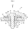
- Fig. 1 is a cross-section illustrating a fastening structure 10 according to the first exemplary embodiment.
- the fastening structure 10 includes a metal member 12 with a plate shape, and a plate-shaped resin member 14 that overlaps the metal member 12.
- a circular-shaped through-hole 12A, serving as a first through-hole, is formed in the metal member 12, and a shaft portion 22A of a flange bolt 22, serving as a fastener, is inserted inside the through-hole 12A.
- a circular-shaped through-hole 14A serving as a second through-hole and set with a larger diameter than the through-hole 12A, is formed in the resin member 14.
- a circular plate-shaped flange portion 20 juts out toward the outside of the tube portion 18 from an upper end portion of the tube portion 18.
- the flange portion 20 is disposed facing an upper face 14B of the resin member 14.
- a lower face 22B of a flange portion 22B of the flange bolt 22 is capable of abutting an upper face 20A of the flange portion 20.
- Sealing rubber 24 (described later), serving as a bottomed, tube-shaped elastic member with one open end, is integrally molded to the collar 16 so as to cover an outer peripheral face 20B serving as an outside face of the flange portion 20, and a lower face 20C serving as a face facing the resin member 14.
- a weld nut 26 is provided coaxially to the through-hole 12A at a lower face 12B of the metal member 12, and is capable of being screwed together with the shaft portion 22A of the flange bolt 22 that has passed through the through-hole 18A of the collar 16 and the through-hole 12A of the metal member 12.
- a protruding portion 28 is continuously formed along the circumferential direction around the through-hole 14A in the upper face 14B (the face at the opposite side to the metal member 12) of the resin member 14, at the through-hole 14A side positioned below the flange portion 22B of the flange bolt 22.
- a cross-section profile of the protruding portion 28 sectioned along the up-down direction forms a triangular shape.
- the sealing rubber 24 is integrally molded to the outer peripheral face 20B and the lower face 20C of the flange portion 20 of the collar 16 in the present exemplary embodiment.
- the protruding portion 28 is continuously formed along the circumferential direction around the through-hole 14A in the upper face 14B of the resin member 14, at the through-hole 14A side positioned below the flange portion 22B of the flange bolt 22.
- the metal member 12 and the resin member 14 overlap each other.
- the collar 16 is disposed inside the through-hole 14A of the resin member 14 so that the through-hole 18A of the tube portion 18 and the through-hole 12A of the metal member 12 are also disposed substantially coaxially to each other.
- the flange bolt 22 is screwed together with the weld nut 26 provided at the lower face 12B of the metal member 12 in this state.
- the sealing rubber 24 provided to the collar 16 is press-contacted against the resin member 14, and the protruding portion 28 of the resin member 14 digs into the sealing rubber 24, due to the fastening force of the flange bolt 22. Sealing performance between the metal member 12 and the resin member 14 is improved by the press-contact force of the sealing rubber 24 in this manner.
- the protruding portion 28 of the resin member 14 digs into the sealing rubber 24 provided to the collar 16, such that the above-described issue does not arise.
- the configuration of the present exemplary embodiment is effective in cases in which a fiber reinforced plastic is employed as the material of the resin member 14.
- the outer peripheral face 20B and the lower face 20C of the flange portion 20 of the collar 16 are covered by the sealing rubber 24.
- the outer peripheral face 20B of the flange portion 20 is covered in a state in which the sealing rubber 24 wraps around an edge portion 20C1 of the lower face 20C of the flange portion 20.
- the fastening structure 10 of the present exemplary embodiment thereby enables water, dust, and the like to be suppressed or prevented from entering between the metal member 12 and the resin member 14, compared to, for example, a case in which only a lower face of a flange portion is covered by sealing rubber, not illustrated in the drawings.
- the protruding portion 28 of the resin member 14 is set so as to dig into the sealing rubber 24 in the state in which the resin member 14 has been fastened to the metal member 12 by the flange bolt 22 and the weld nut 26. This enables rattling about between the resin member 14 and the collar 16 to be suppressed or prevented, even when the plate thickness of the resin member 14 has decreased due to creep deformation.
- the protruding portion 28 formed on the resin member 14 digs into the sealing rubber 24.
- This enables relative movement between the resin member 14 and the sealing rubber 24 to be restricted in the shear direction (a direction orthogonal to the fastening direction of the flange bolt 22) by the protruding portion 28.
- the sealing rubber 24 is integrally provided to the collar 16, thereby enabling relative movement between the collar 16 and the resin member 14 to be restricted in the shear direction as a result.
- the protruding portion 28 is continuously formed along the circumferential direction around the through-hole 14A, thereby enabling the sealing performance between the metal member 12 and the resin member 14 to be further improved by the protruding portion 28.
- the cross-section profile of the protruding portion 28 sectioned along the up-down direction forms a triangular shape. This enables good dig-in performance with respect to the sealing rubber 24.
- the sealing rubber is press-fitted to the collar.
- a press-fitting device is required, and the equipment cost increases.
- an adhesion process is required in addition to the cost of adhesive, such that the equipment cost increases.
- the sealing rubber 24 is integrally molded to the collar 16 by insert molding or the like, such that the above-described issues do not arise. This enables mass production at a low cost.
- the shape of the flange portion 20 formed on the collar 16 illustrated in Fig. 1 is a circular plate shape; however, there is no particular limitation to a circular plate shape, and the flange portion 20 may jut out an angular shape, or a waveform shape.
- the outer profile of the sealing rubber 24 is then formed to match the shape of the flange portion 20.
- the sealing rubber 24 is integrally molded to the collar 16, thereby obtaining an advantageous effect of enabling mass production at a low cost.
- sealing rubber may be integrally provided to the collar by press-fitting or adhering the sealing rubber to the collar.
- the outer peripheral face 20B and the lower face 20C of the flange portion 20 of the collar 16 are covered by the sealing rubber 24; however, the sealing rubber 24 is not necessarily formed across the entire outer peripheral face 20B and the entire lower face 20C of the flange portion 20.
- configuration may be such that part of the outer peripheral face 20B and part of the lower face 20C, including at least the edge portion 20C1 of the lower face 20C of the flange portion 20, are covered by the sealing rubber 24.
- the protruding portion 28 is continuously formed along the circumferential direction around the through-hole 14A. Namely, a single-protrusion protruding portion 28 is formed; however, a double-protrusion or a triple-protrusion protruding portion 28 may be formed. In the present invention, it is sufficient as long as sealing performance between the resin member 14 and the sealing rubber 24 can be secured. There is accordingly no limitation to the protruding portion 28, and for example, a configuration may be applied in which a groove portion is provided to the resin member 14, and a projection portion which fits into the groove portion is formed on the sealing rubber 24, not illustrated in the drawings.
- the protruding portion 28 of the present exemplary embodiment has a cross-section profile sectioned along the up-down direction formed in a triangular shape, thereby improving dig-in performance with respect to the sealing rubber 24.
- the cross-section profile of the protruding portion 28 is not limited to a triangular shape.
- a trapezoidal shape, for example, may be formed.
- the protruding portion 28 is continuously formed along the circumferential direction around the through-hole 14A; however the protruding portion 28 may be intermittently formed. Forming the protruding portion 28 intermittently enables relative movement between the collar 16 and the resin member 14 to be restricted by the flange bolt 22 in the shear direction orthogonal to the fastening direction.
- the protruding portion 28 is provided below the flange portion 22B of the flange bolt 22; however, the fastening force due to the flange bolt 22 is transmitted through the collar 16, and so it is sufficient as long as the protruding portion 28 is provided below the collar 16 at least.
- the flange bolt 22 has been explained as an example of a fastener; however, the fastener is not necessarily the flange bolt 22, and may be a hexagonal bolt. In cases in which the hexagonal bolt is employed, a metal washer or other washer may be employed.
- the weld nut 26 is provided to the lower face 12B of the metal member 12; however, this member does not necessarily have to be the weld nut 26.
- FIG. 2 is a cross-section illustrating a fastening structure 30 according to the second exemplary embodiment. Note that members with substantially the same operation as the first exemplary embodiment are appended with the same reference numerals, and detailed explanation (including operation) thereof is omitted.
- a plate-shaped resin member 32 overlaps the plate-shaped metal member 12.
- a circular-shaped through-hole 32A serving as a second through-hole and set with a larger diameter than the through-hole 12A formed in the metal member 12, is formed in the resin member 32.
- a tube portion 36 provided to a collar 34 made of metal, is capable of being inserted inside the through-hole 32A.
- a through-hole 36A serving as a third through-hole, is formed in the tube portion 36.
- a shaft portion 40A of a flange bolt 40 serving as a fastener, is inserted through the through-hole 36A.
- a circular plate-shaped flange portion 38 juts out toward the outside of the tube portion 36 from an upper end portion of the tube portion 36.
- the flange portion 38 is disposed facing an upper face 32B of the resin member 32.
- a lower face 40B1 of a head portion 40B of the flange bolt 40 is capable of abutting an upper face 38A of the flange portion 38.
- a depressed portion 42 is provided to the upper face 38A of the flange portion 38, further to the outside than an outer peripheral face 36B of the tube portion 36, and is formed a step lower than the upper face 38A of the flange portion 38.
- a projection portion 44 that projects out toward the resin member 32 side at an outer edge portion of the flange portion 38 is continuously formed along the circumferential direction around the through-hole 32A of the resin member 32 at a lower face 38C of the flange portion 38.
- a leading end side of the projection portion 44 forms a shape projecting toward the resin member 32 side, and a leading end portion of the projection portion 44 is curved.
- a cross-section profile of the projection portion 44 sectioned along the up-down direction may be formed in a semicircular shape, a triangular shape, a trapezoidal shape, or the like.
- Substantially tube-shaped sealing rubber 46 serving as an elastic member, is integrally molded to the collar 34 so as to cover the depressed portion 42 of the flange portion 38, an outer peripheral face 38B serving as an outside face of the flange portion 38, and the lower face 38C of the flange portion 38.
- the sealing rubber 46 extends from the outer peripheral face 38B of the flange portion 38 of the collar 34 as far as a region facing (contacting) the head portion 40B of the flange bolt 40.
- an upper face 46A of the sealing rubber 46 is set so as not to be lower than the upper face 38A of the flange portion 38. Namely, the upper face 46A of the sealing rubber 46 is set so as to reliably abut the lower face 40B1 of the head portion 40B of the flange bolt 40.
- a press-contact portion 48 that projects out toward the resin member 32 side is continuously formed along the circumferential direction around the through-hole 32A of the resin member 32 at an outer edge portion of the sealing rubber 46.
- the press-contact portion 48 is formed in a position overlapping the projection portion 44 formed on the flange portion 38 of the collar 34, as viewed from the direction in which the fastening force of the flange bolt 40 and the weld nut 26 acts.
- a leading end side of the press-contact portion 48 forms a bulge-shape bulging toward the resin member 32 side, and a leading end portion of the press-contact portion 48 is curved.
- a cross-section profile of the press-contact portion 48 sectioned along the up-down direction may be formed in a semicircular shape, a triangular shape, a trapezoidal shape, or the like, and the shape of the press-contact portion 48 is not necessarily the same as the shape of the projection portion 44.
- a portion of the press-contact portion 48 is pressed against the upper face 32B of the resin member 32 by the fastening force of the flange bolt 40 and the weld nut 26, and undergoes elastic deformation. Namely, the press-contact portion 48 undergoes elastic deformation in a state in which the resin member 32 has been fastened to the metal member 12 by the flange bolt 40 and the weld nut 26, and is elastically press-contacted against the resin member 32.
- the sealing rubber 46 provided to the collar 34 is thereby press-contacted against the resin member 32, and the press-contact portion 48 of the sealing rubber 46 is elastically press-contacted against the resin member 32, by the fastening force due to the flange bolt 40 and the weld nut 26.
- the sealing performance between the metal member 12 and the resin member 32 is improved by the press-contact force of the sealing rubber 24 in this manner.
- the press-contact portion 48 of the sealing rubber 46 is elastically press-contacted against the resin member 32, thereby enabling relative movement between the collar 34 and the resin member 32 to be restricted by the flange bolt 40 and the weld nut 26 in the shear direction orthogonal to the fastening direction.
- the depressed portion 42 of the flange portion 38 of the collar 34, the outer peripheral face 38B serving as the outside face of the flange portion 38, and the lower face 38C of the flange portion 38 are covered by the sealing rubber 24.
- the outer peripheral face 38B of the flange portion 38 is covered in a state in which the sealing rubber 24 wraps around an edge portion 38C1 of the lower face 38C of the flange portion 38.
- the fastening structure 30 of the present exemplary embodiment thereby enables water, dust, and the like to be suppressed or prevented from entering between the collar 34 and the resin member 32, compared to, for example, a case in which only a lower face of a flange portion is covered by sealing rubber, not illustrated in the drawings.
- the sealing rubber 46 extends from the outer peripheral face 38B of the flange portion 38 of the collar 34 as far as a region facing the head portion 40B of the flange bolt 40, such that the sealing rubber 46 is also provided between the flange portion 38 and the head portion 40B of the flange bolt 40. This enables water, dust, and the like to also be suppressed or prevented from entering between the collar 34 and the flange bolt 40.
- the press-contact portion 48 of the sealing rubber 46 is set so as to be elastically press-contacted against the resin member 32. This enables rattling about between the resin member 32 and the collar 34 to be suppressed or prevented, even when the plate thickness of the resin member 32 has decreased due to creep deformation.
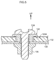
- a protruding portion 100A that abuts a fiber reinforced plastic 102 is provided to a collar 100 made of metal.
- the protruding portion 100A is made to dig into the fiber reinforced plastic 102 by fastening force due to a flange bolt 104 and a weld nut 106, since the fiber reinforced plastic 102 has a high strength, the protruding portion 100A sometimes does not dig into the fiber reinforced plastic 102.
- Electro-deposition (ED) coating (electrolytic corrosion coating) is applied in advance to the surfaces of the collar 100 and a metal member 108 in order to prevent corrosion; however, there is a possibility of this ED coating flaking off when attempting to make the protruding portion 100A dig into the fiber reinforced plastic 102 with undue force. In such cases, there is a possibility of galvanic corrosion (electrolytic corrosion) occurring due to the contact between the fiber reinforced plastic 102 and the collar 100.
- ED Electro-deposition
- the sealing rubber 46 is provided between the collar 34 made of metal and the resin member 32, such that there is no direct contact between the collar 34 and the resin member 32.
- the issue of electrolytic corrosion does not arise in the present exemplary embodiment.
- the projection portion 44 formed on the flange portion 38 of the collar 34 and the press-contact portion 48 formed on the sealing rubber 46 are formed in positions overlapping each other, as viewed from the direction in which the fastening force due to the flange bolt 40 and the weld nut 26 acts. This enables the sealing rubber 46 to be pressed against the resin member 32 by the projection portion 44 of the collar 34. The press-contact force against the resin member 32 by the press-contact portion 48 formed on the sealing rubber 46 is thereby increased.
- the adhesive 58 can be used to temporarily hold the resin member 54 and the metal member 56 together prior to fastening using the flange bolt 60 and the weld nut 26.
- An accumulation portion 62 that has a recessed shape with respect to a coating face 56A of the adhesive 58 may be provided in close proximity to a coating region of the adhesive 58. Excess adhesive 58 thereby flows into the accumulation portion 62; however, this accumulation portion 62 is not necessarily required.
Landscapes
- Engineering & Computer Science (AREA)
- General Engineering & Computer Science (AREA)
- Mechanical Engineering (AREA)
- Bolts, Nuts, And Washers (AREA)
- Connection Of Plates (AREA)
- Gasket Seals (AREA)
Abstract
Description
- The present invention relates to a fastening structure for fastening and fixing a resin member to a metal member.
- In a component fastening structure described in Japanese Patent Application Laid-Open (
JP-A) No. 2012-251583 JP-ANos. 2007-263300 2008-304023 - In consideration of the above circumstances, an object of the present invention is to obtain a fastening structure capable of improving sealing performance between a metal member and a resin member.
- A first aspect of the present invention provides a fastening structure including: a plate-shaped metal member that is formed with a first through-hole through which a fastener is inserted; a plate-shaped resin member that overlaps the metal member, that is formed with a second through-hole with a larger diameter than the first through-hole, and that is fastened to a metal member by the fastener; a collar that is made of metal and is includes a tube portion inserted into the second through-hole and formed with a third through-hole through which the fastener is inserted, and a flange portion disposed facing the resin member in a state in which the tube portion has been inserted into the second through-hole; and an elastic member that is integrally provided at the collar, that is disposed between the flange portion and the resin member, and that covers an outside face of the flange portion and a face of the flange portion facing the resin member.
- In the above configuration, the plate-shaped resin member overlaps the plate-shaped metal member and they are fastened together by the fastener. The first through-hole through which the fastener is inserted is formed in the metal member, and the second through-hole that has a larger diameter than the first through-hole is formed in the resin member. The tube portion that configures part of the collar made of metal is capable of being inserted into the second through-hole, and the flange portion is disposed facing the resin member in the state in which the tube portion has been inserted into the second through-hole.
- The elastic member is integrally provided at the collar. The elastic member is disposed between the flange portion of the collar and the resin member, and covers the outside face (that has a round shape, an angular shape, a wave shape, or the like) of the flange portion and a face of the flange portion facing the resin member. This enables water, dust, and the like to be suppressed or prevented from entering between the metal member and the resin member. Note that "integrally" referred to herein includes, as well as cases in which the collar and the elastic member have been integrally formed by molding as an integral unit, cases in which the collar and the elastic member have been integrated together by press-fitting, adhesive, or the like.
- A second aspect of the present invention is the first aspect of the present invention, wherein the resin member may include a protruding portion that digs into the elastic member in a state in which the resin member has been fastened to the metal member by the fastener.
- In the above configuration, the protruding portion that digs into the elastic member in the state in which the resin member has been fastened to the metal member by the fastener is formed on the resin member. This enables relative movement between the resin member and the elastic member to be restricted in a shear direction (a direction orthogonal to a fastening direction of the fastener) by the protruding portion. Since the elastic member is integrally provided to the collar, relative movement between the collar and the resin member can be restricted in the shear direction as a result.
- A third aspect of the present invention is the second aspect of the present invention, wherein the protruding portion may be continuously formed around the second through-hole.
- In the above configuration, the protruding portion is continuously formed around the second through-hole, thereby enabling sealing performance between the metal member and the resin member to be further improved by the protruding portion.
- A fourth aspect of the present invention is the second aspect of the present invention, wherein the protruding portion is intermittently formed around the second through-hole.
- In the above configuration, the protruding portion is intermittently formed around the second through-hole, thereby enabling relative movement between the collar and the resin member, in the shear direction orthogonal to the fastening direction by the fastener, to be restricted.
- A fifth aspect of the present invention is any one of the first aspect to the fourth aspect of the present invention, wherein, on the elastic member, a press-contact portion may be provided that is press-contacted against the resin member in a state in which the resin member has been fastened to the metal member by the fastener.
- In the above configuration, the press-contact portion that is press-contacted against the resin member in the state in which the resin member has been fastened to the metal member by the fastener is formed on the elastic member, thereby enabling sealing performance between the collar and the resin member to be improved by the press-contact portion.
- A sixth aspect of the present invention is any one of the first aspect to the fifth aspect of the present invention, wherein, on the collar, a projection portion is formed that projects toward a side of the resin member at a position of the flange portion facing the resin member.
- In the above configuration, on the flange portion of the collar, the projection portion is formed projecting toward a side of the resin member at a position facing the resin member, thereby enabling the elastic member to be pressed by the projection portion against the resin member. This enables sealing performance between the collar and the resin member to be further improved.
- A seventh aspect of the present invention is the sixth aspect of the present invention, wherein on the elastic member, a press-contact portion that is press-contacted against the resin member in a state in which the resin member has been fastened to the metal member by the fastener, and the projection portion, are provided in positions that overlap with each other as viewed from a direction in which fastening force due to the fastener acts.
- In the above configuration, the press-contact portion formed at the elastic member side of the collar, and the projection portion formed at the flange portion side of the collar, are provided in positions that overlap with each other as viewed from the direction in which fastening force due to the fastener acts. Thus, in the state in which the resin member has been fastened to the metal member by the fastener, a pressing force acts on the elastic member due to the projection portion of the collar.
- Press-contact force against the resin member due to the press-contact portion thereby increases, thereby enabling sealing performance between the collar and the resin member to be further increased compared to, for example, cases in which the press-contact portion and the projection portion are provided in positions that are offset from each other viewed from the direction in which fastening force due to the fastener acts.
- An eighth aspect of the present invention is any one of the fifth aspect to the seventh aspect of the present invention, wherein on the elastic member, a press-contact portion that is press-contacted against the resin member in a state in which the resin member has been fastened to the metal member by the fastener is continuously formed around the second through-hole.
- In the above configuration, the press-contact portion formed at the elastic member side of the collar is continuously formed around the second through-hole formed in the resin member, thereby enabling sealing performance between the collar and the resin member to be further improved by the press-contact portion.
- A ninth aspect of the present invention is any one of the fifth aspect to the seventh aspect of the present invention, wherein on the elastic member, a press-contact portion that is press-contacted against the resin member in a state in which the resin member has been fastened to the metal member by the fastener is intermittently formed around the second through-hole.
- In the above configuration, the press-contact portion formed at the elastic member of the collar is intermittently formed around the second through-hole formed in the resin member, thereby enabling relative movement between the collar and the resin member, in the shear direction orthogonal to the fastening direction by the fastener, to be restricted.
- A tenth aspect of the present invention is any one of the sixth aspect to the ninth aspect of the present invention, wherein on the collar, a projection portion that projects toward the resin member side at a position of the flange portion facing the resin member, is continuously formed around the second through-hole.
- In the above configuration, the projection portion formed on the flange portion of the collar is continuously formed around the second through-hole formed in the resin member, thereby enabling sealing performance between the collar and the resin member to be further improved by the projection portion.
- An eleventh aspect of the present invention is any one of the sixth aspect to the ninth aspect of the present invention, wherein on the collar, a projection portion that projects toward the resin member side at a position of the flange portion facing the resin member is intermittently formed around the second through-hole.
- In the above configuration, the projection portion formed on the flange portion of the collar is intermittently formed around the second through-hole formed in the resin member, thereby enabling relative movement between the collar and the resin member, in the shear direction orthogonal to the fastening direction by the fastener, to be restricted.
- A twelfth aspect of the present invention is any one of the first aspect to the eleventh aspect of the present invention, wherein the elastic member wraps around the outside face of the flange portion and extends as far as a region contacting the fastener.
- In the above configuration, the elastic member extends from the outside face of the flange portion of the collar as far as a region contacting the fastener, such that the elastic member is also provided between the flange portion and the fastener. This enables water, dust, and the like to be suppressed or prevented from entering between the collar and the fastener.
- A thirteenth aspect of the present invention is any one of the first aspect to the twelfth aspect of the present invention, wherein the elastic member is integrally molded to the collar.
- In the above configuration, the elastic member is integrally molded to the collar, thereby reducing manufacturing costs compared to, for example, cases in which the elastic member is press-fitted to the collar.
- The first aspect of the present invention has an excellent advantageous effect of enabling the sealing performance between the metal member and the resin member to be improved.
- The second aspect of the present invention has an excellent advantageous effect of enabling relative movement between the collar and the resin member, in the shear direction orthogonal to the fastening direction by the fastener, to be restricted by the protruding portion formed on the resin member.
- The third aspect of the present invention has an excellent advantageous effect of enabling the sealing performance between the metal member and the resin member to be further improved by the protruding portion formed on the resin member.
- The fourth aspect of the present invention has an excellent advantageous effect of enabling relative movement between the collar and the resin member, in the shear direction orthogonal to the fastening direction by the fastener, to be restricted by the protruding portion formed on the elastic member of the collar.
- The fifth aspect of the present invention has an excellent advantageous effect of enabling relative movement between the collar and the resin member, in the shear direction orthogonal to the fastening direction by the fastener, to be restricted by the press-contact portion formed on the elastic member of the collar.
- The sixth aspect of the present invention has an excellent advantageous effect of enabling relative movement between the collar and the resin member, relative movement between the collar and the resin member, in the shear direction orthogonal to the fastening direction by the fastener, to be restricted by the projection portion formed on the flange portion of the collar.
- The seventh aspect of the present invention enables relative movement between the collar and the resin member in the shear direction to be further restricted by the projection portion formed on the flange portion of the collar and the press-contact portion formed on the elastic member.
- The eighth aspect of the present invention has an excellent advantageous effect of enabling the sealing performance between the collar and the resin member to be further improved by the press-contact portion formed on the elastic member of the collar.
- The ninth aspect of the present invention has an excellent advantageous effect of enabling relative movement between the collar and the resin member, in the shear direction orthogonal to the fastening direction by the fastener, to be restricted by the press-contact portion formed on the elastic member of the collar.
- The tenth aspect of the present invention has an excellent advantageous effect of enabling the sealing performance between the collar and the resin member to be further improved by the projection portion formed on the flange portion of the collar, and the elastic member.
- The eleventh aspect of the present invention has an excellent advantageous effect of enabling relative movement between the collar and the resin member, in the shear direction orthogonal to the fastening direction by the fastener, to be restricted by the projection portion formed on the flange portion of the collar and the elastic member.
- The twelfth aspect of the present invention has an excellent advantageous effect of enabling water, dust, and the like to be suppressed or prevented from entering between the collar and the fastener, by the elastic member of the collar.
- The thirteenth aspect of the present invention has an excellent advantageous effect of enabling a reduction in cost to be achieved.
-
-
Fig. 1 is a cross-section illustrating a fastening structure according to a first exemplary embodiment. -
Fig. 2 is a cross-section illustrating a fastening structure according to a second exemplary embodiment. -
Fig. 3 is a cross-section illustrating a modified example (1) of a fastening structure according to the second exemplary embodiment. -
Fig. 4 is a cross-section illustrating a modified example (2) of a fastening structure according to the second exemplary embodiment. -
Fig. 5 is a cross-section corresponding toFig. 2 , illustrating a comparative example. - Explanation follows regarding exemplary embodiments of a fastening structure according to the present invention, with reference to the drawings. Note that for ease of explanation, the arrow UP indicates the up-down direction in the respective drawings, and "up" and "down" are sometimes added to the explanation based on this; however, the direction of the respective portions is not limited by adding "up" and "down" to the explanation.
- Explanation first follows regarding a fastening structure according to a first exemplary embodiment.
Fig. 1 is a cross-section illustrating afastening structure 10 according to the first exemplary embodiment. As illustrated inFig. 1 , thefastening structure 10 includes ametal member 12 with a plate shape, and a plate-shapedresin member 14 that overlaps themetal member 12. A circular-shaped through-hole 12A, serving as a first through-hole, is formed in themetal member 12, and ashaft portion 22A of aflange bolt 22, serving as a fastener, is inserted inside the through-hole 12A. - A circular-shaped through-
hole 14A, serving as a second through-hole and set with a larger diameter than the through-hole 12A, is formed in theresin member 14. Atube portion 18, provided to acollar 16 made of metal, is capable of being inserted inside the through-hole 14A. A through-hole 18A, serving as a third through-hole through which theshaft portion 22A of theflange bolt 22, serving as the fastener, is inserted, is formed in thetube portion 18. - A circular plate-shaped
flange portion 20 juts out toward the outside of thetube portion 18 from an upper end portion of thetube portion 18. Theflange portion 20 is disposed facing anupper face 14B of theresin member 14. Alower face 22B of aflange portion 22B of theflange bolt 22 is capable of abutting anupper face 20A of theflange portion 20. Sealing rubber 24 (described later), serving as a bottomed, tube-shaped elastic member with one open end, is integrally molded to thecollar 16 so as to cover an outerperipheral face 20B serving as an outside face of theflange portion 20, and alower face 20C serving as a face facing theresin member 14. - A
weld nut 26 is provided coaxially to the through-hole 12A at alower face 12B of themetal member 12, and is capable of being screwed together with theshaft portion 22A of theflange bolt 22 that has passed through the through-hole 18A of thecollar 16 and the through-hole 12A of themetal member 12. - Note that a protruding
portion 28 is continuously formed along the circumferential direction around the through-hole 14A in theupper face 14B (the face at the opposite side to the metal member 12) of theresin member 14, at the through-hole 14A side positioned below theflange portion 22B of theflange bolt 22. A cross-section profile of the protrudingportion 28 sectioned along the up-down direction forms a triangular shape. - As illustrated in
Fig. 1 and as described above, the sealingrubber 24 is integrally molded to the outerperipheral face 20B and thelower face 20C of theflange portion 20 of thecollar 16 in the present exemplary embodiment. The protrudingportion 28 is continuously formed along the circumferential direction around the through-hole 14A in theupper face 14B of theresin member 14, at the through-hole 14A side positioned below theflange portion 22B of theflange bolt 22. - In a state in which the through-
hole 12A of themetal member 12 and the through-hole 14A of theresin member 14 are disposed substantially coaxially to each other, themetal member 12 and theresin member 14 overlap each other. Thecollar 16 is disposed inside the through-hole 14A of theresin member 14 so that the through-hole 18A of thetube portion 18 and the through-hole 12A of themetal member 12 are also disposed substantially coaxially to each other. - The
flange bolt 22 is screwed together with theweld nut 26 provided at thelower face 12B of themetal member 12 in this state. In a state in which theresin member 14 has been fastened to themetal member 12 by theflange bolt 22 and theweld nut 26, the sealingrubber 24 provided to thecollar 16 is press-contacted against theresin member 14, and the protrudingportion 28 of theresin member 14 digs into the sealingrubber 24, due to the fastening force of theflange bolt 22. Sealing performance between themetal member 12 and theresin member 14 is improved by the press-contact force of the sealingrubber 24 in this manner. - In particular, in cases in which a fiber reinforced plastic is employed as the material of the
resin member 14, even when, for example, a protruding portion abutting the fiber reinforced plastic is provided to a collar made of metal, not illustrated in the drawings, since the fiber reinforced plastic has a high strength, sometimes the protruding portion does not dig into the fiber reinforced plastic. It is difficult to secure sealing performance between the metal member and the resin member in such cases. - However, in the present exemplary embodiment, the protruding
portion 28 of theresin member 14 digs into the sealingrubber 24 provided to thecollar 16, such that the above-described issue does not arise. Thus the configuration of the present exemplary embodiment is effective in cases in which a fiber reinforced plastic is employed as the material of theresin member 14. - The outer
peripheral face 20B and thelower face 20C of theflange portion 20 of thecollar 16 are covered by the sealingrubber 24. Namely, in the present exemplary embodiment, the outerperipheral face 20B of theflange portion 20 is covered in a state in which the sealingrubber 24 wraps around an edge portion 20C1 of thelower face 20C of theflange portion 20. Thefastening structure 10 of the present exemplary embodiment thereby enables water, dust, and the like to be suppressed or prevented from entering between themetal member 12 and theresin member 14, compared to, for example, a case in which only a lower face of a flange portion is covered by sealing rubber, not illustrated in the drawings. - As described above, in the present exemplary embodiment, the protruding
portion 28 of theresin member 14 is set so as to dig into the sealingrubber 24 in the state in which theresin member 14 has been fastened to themetal member 12 by theflange bolt 22 and theweld nut 26. This enables rattling about between theresin member 14 and thecollar 16 to be suppressed or prevented, even when the plate thickness of theresin member 14 has decreased due to creep deformation. - In cases in which a fiber reinforced plastic containing carbon is employed as the material of the
resin member 14, for example, there is possibility of electrolytic corrosion occurring if theresin member 14 contacts metal. However, in the present exemplary embodiment, thecollar 16 made of metal and theresin member 14 do not contact each other directly, and so the issue of electrolytic corrosion does not arise. - In the present exemplary embodiment, in the state in which the
resin member 14 has been fastened to themetal member 12 by theflange bolt 22 and theweld nut 26, the protrudingportion 28 formed on theresin member 14 digs into the sealingrubber 24. This enables relative movement between theresin member 14 and the sealingrubber 24 to be restricted in the shear direction (a direction orthogonal to the fastening direction of the flange bolt 22) by the protrudingportion 28. Note that the sealingrubber 24 is integrally provided to thecollar 16, thereby enabling relative movement between thecollar 16 and theresin member 14 to be restricted in the shear direction as a result. - In the present exemplary embodiment, the protruding
portion 28 is continuously formed along the circumferential direction around the through-hole 14A, thereby enabling the sealing performance between themetal member 12 and theresin member 14 to be further improved by the protrudingportion 28. - The cross-section profile of the protruding
portion 28 sectioned along the up-down direction forms a triangular shape. This enables good dig-in performance with respect to the sealingrubber 24. - In cases in which a collar is formed with sealing rubber as an integral unit, for example, the sealing rubber is press-fitted to the collar. In such cases, a press-fitting device is required, and the equipment cost increases. In cases in which sealing rubber is adhered to a collar, an adhesion process is required in addition to the cost of adhesive, such that the equipment cost increases. In contrast thereto, in the present exemplary embodiment, the sealing
rubber 24 is integrally molded to thecollar 16 by insert molding or the like, such that the above-described issues do not arise. This enables mass production at a low cost. - In the present exemplary embodiment, the shape of the
flange portion 20 formed on thecollar 16 illustrated inFig. 1 is a circular plate shape; however, there is no particular limitation to a circular plate shape, and theflange portion 20 may jut out an angular shape, or a waveform shape. The outer profile of the sealingrubber 24 is then formed to match the shape of theflange portion 20. - In the present exemplary embodiment, the sealing
rubber 24 is integrally molded to thecollar 16, thereby obtaining an advantageous effect of enabling mass production at a low cost. However, it is sufficient as long as the sealingrubber 24 is integrally provided to thecollar 16 in the present invention. Thus it goes without saying that, from the perspective of using an existing collar, sealing rubber may be integrally provided to the collar by press-fitting or adhering the sealing rubber to the collar. - In the present exemplary embodiment, the outer
peripheral face 20B and thelower face 20C of theflange portion 20 of thecollar 16 are covered by the sealingrubber 24; however, the sealingrubber 24 is not necessarily formed across the entire outerperipheral face 20B and the entirelower face 20C of theflange portion 20. For example, configuration may be such that part of the outerperipheral face 20B and part of thelower face 20C, including at least the edge portion 20C1 of thelower face 20C of theflange portion 20, are covered by the sealingrubber 24. - In the present exemplary embodiment, the protruding
portion 28 is continuously formed along the circumferential direction around the through-hole 14A. Namely, a single-protrusion protruding portion 28 is formed; however, a double-protrusion or a triple-protrusion protruding portion 28 may be formed. In the present invention, it is sufficient as long as sealing performance between theresin member 14 and the sealingrubber 24 can be secured. There is accordingly no limitation to the protrudingportion 28, and for example, a configuration may be applied in which a groove portion is provided to theresin member 14, and a projection portion which fits into the groove portion is formed on the sealingrubber 24, not illustrated in the drawings. - The protruding
portion 28 of the present exemplary embodiment has a cross-section profile sectioned along the up-down direction formed in a triangular shape, thereby improving dig-in performance with respect to the sealingrubber 24. However, the cross-section profile of the protrudingportion 28 is not limited to a triangular shape. A trapezoidal shape, for example, may be formed. - In the present exemplary embodiment, the protruding
portion 28 is continuously formed along the circumferential direction around the through-hole 14A; however the protrudingportion 28 may be intermittently formed. Forming the protrudingportion 28 intermittently enables relative movement between thecollar 16 and theresin member 14 to be restricted by theflange bolt 22 in the shear direction orthogonal to the fastening direction. - The protruding
portion 28 is provided below theflange portion 22B of theflange bolt 22; however, the fastening force due to theflange bolt 22 is transmitted through thecollar 16, and so it is sufficient as long as the protrudingportion 28 is provided below thecollar 16 at least. - In the present exemplary embodiment, the
flange bolt 22 has been explained as an example of a fastener; however, the fastener is not necessarily theflange bolt 22, and may be a hexagonal bolt. In cases in which the hexagonal bolt is employed, a metal washer or other washer may be employed. - In the present exemplary embodiment, the
weld nut 26 is provided to thelower face 12B of themetal member 12; however, this member does not necessarily have to be theweld nut 26. - Explanation follows regarding a fastening structure according to a second exemplary embodiment.
Fig. 2 is a cross-section illustrating afastening structure 30 according to the second exemplary embodiment. Note that members with substantially the same operation as the first exemplary embodiment are appended with the same reference numerals, and detailed explanation (including operation) thereof is omitted. - As illustrated in
Fig. 2 , similarly to in the first exemplary embodiment, in thefastening structure 30, a plate-shapedresin member 32 overlaps the plate-shapedmetal member 12. A circular-shaped through-hole 32A, serving as a second through-hole and set with a larger diameter than the through-hole 12A formed in themetal member 12, is formed in theresin member 32. Atube portion 36, provided to acollar 34 made of metal, is capable of being inserted inside the through-hole 32A. A through-hole 36A, serving as a third through-hole, is formed in thetube portion 36. Ashaft portion 40A of aflange bolt 40, serving as a fastener, is inserted through the through-hole 36A. - A circular plate-shaped
flange portion 38 juts out toward the outside of thetube portion 36 from an upper end portion of thetube portion 36. Theflange portion 38 is disposed facing anupper face 32B of theresin member 32. A lower face 40B1 of ahead portion 40B of theflange bolt 40 is capable of abutting anupper face 38A of theflange portion 38. - A
depressed portion 42 is provided to theupper face 38A of theflange portion 38, further to the outside than an outerperipheral face 36B of thetube portion 36, and is formed a step lower than theupper face 38A of theflange portion 38. Aprojection portion 44 that projects out toward theresin member 32 side at an outer edge portion of theflange portion 38 is continuously formed along the circumferential direction around the through-hole 32A of theresin member 32 at alower face 38C of theflange portion 38. A leading end side of theprojection portion 44 forms a shape projecting toward theresin member 32 side, and a leading end portion of theprojection portion 44 is curved. Note that a cross-section profile of theprojection portion 44 sectioned along the up-down direction may be formed in a semicircular shape, a triangular shape, a trapezoidal shape, or the like. - Substantially tube-shaped sealing
rubber 46, serving as an elastic member, is integrally molded to thecollar 34 so as to cover thedepressed portion 42 of theflange portion 38, an outerperipheral face 38B serving as an outside face of theflange portion 38, and thelower face 38C of theflange portion 38. Namely, in the present exemplary embodiment, the sealingrubber 46 extends from the outerperipheral face 38B of theflange portion 38 of thecollar 34 as far as a region facing (contacting) thehead portion 40B of theflange bolt 40. - In a state in which the sealing
rubber 46 has covered thedepressed portion 42 of theflange portion 38, anupper face 46A of the sealingrubber 46 is set so as not to be lower than theupper face 38A of theflange portion 38. Namely, theupper face 46A of the sealingrubber 46 is set so as to reliably abut the lower face 40B1 of thehead portion 40B of theflange bolt 40. - A press-
contact portion 48 that projects out toward theresin member 32 side is continuously formed along the circumferential direction around the through-hole 32A of theresin member 32 at an outer edge portion of the sealingrubber 46. The press-contact portion 48 is formed in a position overlapping theprojection portion 44 formed on theflange portion 38 of thecollar 34, as viewed from the direction in which the fastening force of theflange bolt 40 and theweld nut 26 acts. A leading end side of the press-contact portion 48 forms a bulge-shape bulging toward theresin member 32 side, and a leading end portion of the press-contact portion 48 is curved. Note that a cross-section profile of the press-contact portion 48 sectioned along the up-down direction may be formed in a semicircular shape, a triangular shape, a trapezoidal shape, or the like, and the shape of the press-contact portion 48 is not necessarily the same as the shape of theprojection portion 44. - Note that a portion of the press-
contact portion 48, indicated by a phantom line, is pressed against theupper face 32B of theresin member 32 by the fastening force of theflange bolt 40 and theweld nut 26, and undergoes elastic deformation. Namely, the press-contact portion 48 undergoes elastic deformation in a state in which theresin member 32 has been fastened to themetal member 12 by theflange bolt 40 and theweld nut 26, and is elastically press-contacted against theresin member 32. - As illustrated in
Fig. 2 , in the state in which theresin member 32 has been fastened to themetal member 12 by theflange bolt 40 and theweld nut 26, the press-contact portion 48 formed in the sealingrubber 46 provided to thecollar 34 is pressed against theresin member 32, and undergoes elastic deformation. - The sealing
rubber 46 provided to thecollar 34 is thereby press-contacted against theresin member 32, and the press-contact portion 48 of the sealingrubber 46 is elastically press-contacted against theresin member 32, by the fastening force due to theflange bolt 40 and theweld nut 26. The sealing performance between themetal member 12 and theresin member 32 is improved by the press-contact force of the sealingrubber 24 in this manner. - The press-
contact portion 48 of the sealingrubber 46 is elastically press-contacted against theresin member 32, thereby enabling relative movement between thecollar 34 and theresin member 32 to be restricted by theflange bolt 40 and theweld nut 26 in the shear direction orthogonal to the fastening direction. - In the present exemplary embodiment, the
depressed portion 42 of theflange portion 38 of thecollar 34, the outerperipheral face 38B serving as the outside face of theflange portion 38, and thelower face 38C of theflange portion 38 are covered by the sealingrubber 24. - Namely, in the present exemplary embodiment, the outer
peripheral face 38B of theflange portion 38 is covered in a state in which the sealingrubber 24 wraps around an edge portion 38C1 of thelower face 38C of theflange portion 38. Thefastening structure 30 of the present exemplary embodiment thereby enables water, dust, and the like to be suppressed or prevented from entering between thecollar 34 and theresin member 32, compared to, for example, a case in which only a lower face of a flange portion is covered by sealing rubber, not illustrated in the drawings. - In the present exemplary embodiment, the sealing
rubber 46 extends from the outerperipheral face 38B of theflange portion 38 of thecollar 34 as far as a region facing thehead portion 40B of theflange bolt 40, such that the sealingrubber 46 is also provided between theflange portion 38 and thehead portion 40B of theflange bolt 40. This enables water, dust, and the like to also be suppressed or prevented from entering between thecollar 34 and theflange bolt 40. - As described above, in the present exemplary embodiment, in the state in which the
resin member 14 has been fastened to themetal member 12 by theflange bolt 40 and theweld nut 26, the press-contact portion 48 of the sealingrubber 46 is set so as to be elastically press-contacted against theresin member 32. This enables rattling about between theresin member 32 and thecollar 34 to be suppressed or prevented, even when the plate thickness of theresin member 32 has decreased due to creep deformation. - As explained in the first exemplary embodiment, in cases in which a fiber reinforced plastic containing carbon is employed as the material of the
resin member 32, there is a possibility of electrolytic corrosion occurring if the fiber reinforced plastic contacts metal. Specifically, as illustrated inFig. 5 , for example, a protrudingportion 100A that abuts a fiber reinforcedplastic 102 is provided to acollar 100 made of metal. When the protrudingportion 100A is made to dig into the fiber reinforcedplastic 102 by fastening force due to aflange bolt 104 and aweld nut 106, since the fiber reinforcedplastic 102 has a high strength, the protrudingportion 100A sometimes does not dig into the fiber reinforcedplastic 102. - Electro-deposition (ED) coating (electrolytic corrosion coating) is applied in advance to the surfaces of the
collar 100 and ametal member 108 in order to prevent corrosion; however, there is a possibility of this ED coating flaking off when attempting to make the protrudingportion 100A dig into the fiber reinforcedplastic 102 with undue force. In such cases, there is a possibility of galvanic corrosion (electrolytic corrosion) occurring due to the contact between the fiber reinforcedplastic 102 and thecollar 100. - However, in the present exemplary embodiment, as illustrated in
Fig. 2 , the sealingrubber 46 is provided between thecollar 34 made of metal and theresin member 32, such that there is no direct contact between thecollar 34 and theresin member 32. Thus, the issue of electrolytic corrosion does not arise in the present exemplary embodiment. - In the present exemplary embodiment, the
projection portion 44 formed on theflange portion 38 of thecollar 34 and the press-contact portion 48 formed on the sealingrubber 46 are formed in positions overlapping each other, as viewed from the direction in which the fastening force due to theflange bolt 40 and theweld nut 26 acts. This enables the sealingrubber 46 to be pressed against theresin member 32 by theprojection portion 44 of thecollar 34. The press-contact force against theresin member 32 by the press-contact portion 48 formed on the sealingrubber 46 is thereby increased. - This enables the sealing performance between the
collar 34 and theresin member 32 to be further improved compared to, for example, cases in which the press-contact portion 48 and theprojection portion 44 are provided in positions offset from each other viewed from the direction in which the fastening force due to theflange bolt 40 and theweld nut 26 acts.
This also enables relative movement between thecollar 34 and theresin member 32 to be further restricted in the shear direction. Note that it goes without saying that the press-contact portion 48 and theprojection portion 44 may be provided in positions offset from each other viewed from the direction in which the fastening force due to theflange bolt 40 and theweld nut 26 acts. - In the above exemplary embodiments, explanation has mainly been regarding a fastening structure of non-movable members; however, in a fastening structure of members including a movable member, adhesive is sometimes applied between a resin member and a metal member, in addition to the above exemplary embodiments.
- (1) As illustrated in
Fig. 3 , for example, in a hinge section of a vehicle back door or the like, not illustrated in the drawings, in afastening structure 50 applied at a movable side, acollar 34 is provided between aresin member 52 provided at acabin exterior 51 side, and aresin member 54 provided at a back door interior 53 side, to suppress or prevent water, dust, or the like from entering the back door interior 53 side. Ametal member 56 is fastened to theresin member 52, thecollar 34, and theresin member 54 by aflange bolt 60 and theweld nut 26, serving as a fastener, these become an integral unit, and are moved by pivoting in the arrow direction about a pivot axis P of the door. In the present exemplary embodiment, adhesive 58 is provided between theresin member 54 and themetal member 56. - Note that, since the
resin member 54 and themetal member 56 need to be firmly fixed together, relative movement of both members with respect to shear force occurring between theresin member 54 and themetal member 56 is suppressed or prevented, not only by the fastening force due to theflange bolt 60 and theweld nut 26, but also by the adhesive 58. - Note that the adhesive 58 can be used to temporarily hold the
resin member 54 and themetal member 56 together prior to fastening using theflange bolt 60 and theweld nut 26. Anaccumulation portion 62 that has a recessed shape with respect to a coating face 56A of the adhesive 58 may be provided in close proximity to a coating region of the adhesive 58. Excess adhesive 58 thereby flows into theaccumulation portion 62; however, thisaccumulation portion 62 is not necessarily required. - (2) Other than the above exemplary embodiments, as illustrated in
Fig. 4 , application may be made to afastening bolt 70, serving as a fastener coupled to adamper section 66 of a vehicle back door, not illustrated in the drawings. In afastening structure 72 including thefastening bolt 70, apiston 68 configuring part of thedamper section 66 moves in a straight line along its axial direction (the arrow direction), such that moment acts on thefastening bolt 70 about acoupling portion 74 with thepiston 68. There is accordingly a possibility that shear force arises between thefastening bolt 70 and thecollar 34.Adhesive 80 is thereby provided between aresin member 76 and ametal member 78, and relative movement of both members is suppressed or prevented, with respect to shear force occurring between theresin member 76 and themetal member 78, by thecollar 34. - Exemplary embodiments of the present invention have been explained above; however, the present invention is not limited to the above description and obviously various other modifications may be implemented with a range not departing from the spirit of the present invention.
Claims (13)
- A fastening structure, comprising:a plate-shaped metal member that is formed with a first through-hole through which a fastener is inserted;a plate-shaped resin member that overlaps the metal member, that is formed with a second through-hole with a larger diameter than the first through-hole, and that is fastened to a metal member by the fastener;a collar that is made of metal and is includes a tube portion inserted into the second through-hole and formed with a third through-hole through which the fastener is inserted, and a flange portion disposed facing the resin member in a state in which the tube portion has been inserted into the second through-hole; andan elastic member that is integrally provided at the collar, that is disposed between the flange portion and the resin member, and that covers an outside face of the flange portion and a face of the flange portion facing the resin member.
- The fastening structure of claim 1, wherein the resin member includes a protruding portion that digs into the elastic member in a state in which the resin member has been fastened to the metal member by the fastener.
- The fastening structure of claim 2, wherein the protruding portion is continuously formed around the second through-hole.
- The fastening structure of claim 2, wherein the protruding portion is intermittently formed around the second through-hole.
- The fastening structure of any one of claim 1 to claim 4, wherein, on the elastic member, a press-contact portion is provided that is press-contacted against the resin member in a state in which the resin member has been fastened to the metal member by the fastener.
- The fastening structure of any one of claim 1 to claim 5, wherein, on the collar, a projection portion is formed that projects toward a side of the resin member at a position of the flange portion facing the resin member.
- The fastening structure of claim 6, wherein, on the elastic member, a press-contact portion that is press-contacted against the resin member in a state in which the resin member has been fastened to the metal member by the fastener, and the projection portion, are provided in positions that overlap with each other as viewed from a direction in which fastening force due to the fastener acts.
- The fastening structure of any one of claim 5 to claim 7, wherein, on the elastic member, a press-contact portion that is press-contacted against the resin member in a state in which the resin member has been fastened to the metal member by the fastener, is continuously formed around the second through-hole.
- The fastening structure of any one of claim 5 to claim 7, wherein, on the elastic member, a press-contact portion that is press-contacted against the resin member in a state in which the resin member has been fastened to the metal member by the fastener, is intermittently formed around the second through-hole.
- The fastening structure of any one of claim 6 to claim 9, wherein, on the collar, a projection portion that projects toward the resin member side at a position of the flange portion facing the resin member, is continuously formed around the second through-hole.
- The fastening structure of any one of claim 6 to claim 9, wherein, on the collar, a projection portion that projects toward the resin member side at a position of the flange portion facing the resin member, is intermittently formed around the second through-hole.
- The fastening structure of any one of claim 1 to claim 11, wherein the elastic member wraps around the outside face of the flange portion and extends as far as a region contacting the fastener.
- The fastening structure of any one of claim 1 to claim 12, wherein the elastic member is integrally molded to the collar.
Applications Claiming Priority (3)
| Application Number | Priority Date | Filing Date | Title |
|---|---|---|---|
| JP2013242238 | 2013-11-22 | ||
| JP2014181424A JP6156294B2 (en) | 2013-11-22 | 2014-09-05 | Fastening structure |
| PCT/JP2014/080536 WO2015076270A1 (en) | 2013-11-22 | 2014-11-18 | Fastening structure |
Publications (3)
| Publication Number | Publication Date |
|---|---|
| EP3073128A1 true EP3073128A1 (en) | 2016-09-28 |
| EP3073128A4 EP3073128A4 (en) | 2016-12-07 |
| EP3073128B1 EP3073128B1 (en) | 2019-04-10 |
Family
ID=53179531
Family Applications (1)
| Application Number | Title | Priority Date | Filing Date |
|---|---|---|---|
| EP14864873.6A Not-in-force EP3073128B1 (en) | 2013-11-22 | 2014-11-18 | Fastening structure |
Country Status (5)
| Country | Link |
|---|---|
| US (1) | US9746021B2 (en) |
| EP (1) | EP3073128B1 (en) |
| JP (1) | JP6156294B2 (en) |
| CN (1) | CN105765238B (en) |
| WO (1) | WO2015076270A1 (en) |
Cited By (2)
| Publication number | Priority date | Publication date | Assignee | Title |
|---|---|---|---|---|
| US10003113B1 (en) | 2016-12-19 | 2018-06-19 | Ford Global Technologies, Llc | Fastening assembly and method |
| DE102020207094A1 (en) | 2020-06-05 | 2021-12-09 | Volkswagen Aktiengesellschaft | Arrangement of two sealing partners |
Families Citing this family (22)
| Publication number | Priority date | Publication date | Assignee | Title |
|---|---|---|---|---|
| JP6884497B2 (en) * | 2014-11-13 | 2021-06-09 | 三菱重工サーマルシステムズ株式会社 | Motor rotors, motors using them, and electric compressors |
| JP6508962B2 (en) * | 2015-02-13 | 2019-05-08 | 株式会社青山製作所 | Fastening structure of bolt to resin plate |
| EP3211720A1 (en) * | 2016-02-29 | 2017-08-30 | Dubuis et Cie | Earthing bond seal |
| US10184503B2 (en) * | 2016-03-18 | 2019-01-22 | Toyota Jidosha Kabushiki Kaisha | Fastening structure |
| JP6818425B2 (en) * | 2016-04-19 | 2021-01-20 | 日産自動車株式会社 | Fastened structure of fiber reinforced plastic material |
| JP6776635B2 (en) * | 2016-06-07 | 2020-10-28 | トヨタ自動車株式会社 | Fastening member fixing structure of resin member |
| DE102016110754A1 (en) * | 2016-06-10 | 2017-12-14 | Huf Hülsbeck & Fürst Gmbh & Co. Kg | Fastening device for fastening a first component to a second component |
| KR102633072B1 (en) * | 2016-09-20 | 2024-02-02 | 한국단자공업 주식회사 | Bush for connector |
| JP6870345B2 (en) * | 2017-01-30 | 2021-05-12 | 株式会社アイシン | Intake device mounting structure, intake device mounting method and resin member fastening structure |
| JP6820239B2 (en) * | 2017-06-22 | 2021-01-27 | 株式会社ブリヂストン | Bracket for anti-vibration device |
| JP7132564B2 (en) * | 2018-04-10 | 2022-09-07 | 株式会社板野紙工 | cardboard mannequin |
| JP6973271B2 (en) | 2018-04-26 | 2021-11-24 | トヨタ自動車株式会社 | Protector and protector manufacturing method |
| US11339823B2 (en) * | 2018-08-09 | 2022-05-24 | J.S.T. Corporation | System and method for sealing a metal fastener from electrolyte in an area of dissimilar metals |
| JP7093701B2 (en) * | 2018-08-31 | 2022-06-30 | 本田技研工業株式会社 | Fiber reinforced plastic molded product |
| WO2020049961A1 (en) * | 2018-09-05 | 2020-03-12 | Nok株式会社 | Linking device and sealing device |
| US10923863B2 (en) | 2018-12-04 | 2021-02-16 | J.S.T. Corporation | High voltage connector and method for assembling thereof |
| US11476530B2 (en) | 2020-03-10 | 2022-10-18 | Karma Automotive Llc | Vehicle battery assembly |
| JP6797323B1 (en) * | 2020-03-31 | 2020-12-09 | 株式会社トープラ | Screw fastener |
| JP7072698B1 (en) * | 2021-03-26 | 2022-05-20 | 三菱電機株式会社 | Buck converter |
| JP2023141256A (en) * | 2022-03-23 | 2023-10-05 | いすゞ自動車株式会社 | Mounting structure of resin parts |
| JP7831380B2 (en) * | 2023-04-17 | 2026-03-17 | トヨタ自動車株式会社 | Component fastening structure |
| KR20250024300A (en) * | 2023-08-11 | 2025-02-18 | 현대자동차주식회사 | Assembling structure and method for different kind metal panels |
Family Cites Families (35)
| Publication number | Priority date | Publication date | Assignee | Title |
|---|---|---|---|---|
| US2132636A (en) * | 1937-03-30 | 1938-10-11 | Johns Manville | Pipe assembly |
| US2982573A (en) * | 1958-12-12 | 1961-05-02 | Jr John R Mckee | Composite sealing washer |
| US3286577A (en) * | 1964-05-13 | 1966-11-22 | Atlas Bolt And Screw Company | Shouldered washer and fastening element |
| US3500712A (en) * | 1968-07-11 | 1970-03-17 | Illinois Tool Works | Sealing washer unit |
| US3661046A (en) * | 1970-11-09 | 1972-05-09 | Illinois Tool Works | Combination screw |
| US3783734A (en) * | 1972-08-28 | 1974-01-08 | Federal Screw Works | Clamp load indicating and sealing fastener assembly |
| US4175756A (en) * | 1977-02-14 | 1979-11-27 | Garlock Inc. | Combination thrust washer and seal article, apparatus |
| US4238165A (en) * | 1979-01-25 | 1980-12-09 | Illinois Tool Works Inc. | Fastener unit for clamping plastic workpieces |
| JPS6089402U (en) | 1983-11-28 | 1985-06-19 | スズキ株式会社 | Floating fastening device for parts |
| US4732519A (en) * | 1986-12-24 | 1988-03-22 | Illinois Tool Works Inc. | Fastener assembly with axial play |
| US4863329A (en) * | 1988-01-29 | 1989-09-05 | United Technologies Corporation | Resiliently clamped support |
| JPH0240106U (en) * | 1988-09-12 | 1990-03-19 | ||
| JPH07729Y2 (en) * | 1990-04-23 | 1995-01-11 | 矢崎総業株式会社 | Waterproof ring for screw tightened connector housing |
| US5244325A (en) * | 1992-09-28 | 1993-09-14 | Elco Industries, Inc. | Fastener assembly with axially slidable sleeve |
| US6044536A (en) * | 1995-12-23 | 2000-04-04 | Richard Bergner Gmbh & Co. | Method for making an assembly unit |
| US6059503A (en) * | 1998-10-27 | 2000-05-09 | Johnson; H. Thad | Captivated fastener assembly |
| JP3490927B2 (en) * | 1999-05-19 | 2004-01-26 | ニチアス株式会社 | How to attach a vibrating floating washer to the heat shield |
| JP4056209B2 (en) * | 2000-02-29 | 2008-03-05 | 株式会社カナイ | Hardware for wood thinning and hardware for wood thinning |
| JP2001263314A (en) * | 2000-03-17 | 2001-09-26 | Honda Motor Co Ltd | Bolt fastening structure of magnesium alloy member |
| DE20008684U1 (en) * | 2000-05-13 | 2001-09-20 | fischerwerke Artur Fischer GmbH & Co. KG, 72178 Waldachtal | Fastening element for a multi-pane glass and arrangement in the fastening element anchored in a plate-shaped multi-layer body |
| DE10104672B4 (en) * | 2001-02-02 | 2004-04-15 | Kamax-Werke Rudolf Kellermann Gmbh & Co. Kg | Assembly unit consisting of one component and at least one screw |
| US7086688B2 (en) * | 2003-09-16 | 2006-08-08 | Honda Motor Company, Ltd. | Fastening system with bearing member |
| ITTO20040147A1 (en) * | 2004-03-09 | 2004-06-09 | Cnh Italia Spa | FIXING DEVICE WITH NOISE SUPPRESSION IN PARTICULAR TO FIX TWO COMPONENTS SUBJECT TO VIBRATIONS |
| NZ537537A (en) * | 2004-12-24 | 2008-03-28 | Dale Michael Mcintyre | Sanitary washer having peripheral annular rebate on upper and lower faces filled with flexible medium |
| JP2007263300A (en) | 2006-03-29 | 2007-10-11 | Toyota Motor Corp | Resin member fastening structure and resin member manufacturing method |
| US20100251661A1 (en) * | 2007-06-04 | 2010-10-07 | Societa' Bulloneria Europea S.B.E.S.P.A. | Structural fixing system with high clamping force and tightening precision with high corrosion resistance |
| JP2008304023A (en) | 2007-06-11 | 2008-12-18 | Yazaki Corp | Mounting structure for plastic parts |
| JP4895046B2 (en) * | 2007-10-02 | 2012-03-14 | 公益財団法人鉄道総合技術研究所 | Cell structure Porous metal material installation structure |
| US8454290B2 (en) * | 2009-03-04 | 2013-06-04 | Illinois Tool Works Inc. | Bushing assembly |
| JP5625260B2 (en) | 2009-04-21 | 2014-11-19 | 株式会社豊田自動織機 | Fiber reinforced composite material and fastening structure of fiber reinforced composite material |
| US9709171B2 (en) * | 2010-10-04 | 2017-07-18 | Bridgeport Fittings, Inc. | Sealing reducing washer |
| JP5647888B2 (en) * | 2010-12-27 | 2015-01-07 | 東レ株式会社 | Resin member fastening structure |
| DE102011001052A1 (en) * | 2011-03-03 | 2012-09-06 | Böllhoff Verbindungstechnik GmbH | Fastening device with tolerance compensation |
| JP2012251583A (en) * | 2011-06-01 | 2012-12-20 | Toyota Motor Corp | Part fastening structure |
| JP5885248B2 (en) | 2012-04-18 | 2016-03-15 | トヨタ自動車株式会社 | Resin member fastening structure |
-
2014
- 2014-09-05 JP JP2014181424A patent/JP6156294B2/en not_active Expired - Fee Related
- 2014-11-18 WO PCT/JP2014/080536 patent/WO2015076270A1/en not_active Ceased
- 2014-11-18 CN CN201480063417.0A patent/CN105765238B/en not_active Expired - Fee Related
- 2014-11-18 US US15/037,134 patent/US9746021B2/en not_active Expired - Fee Related
- 2014-11-18 EP EP14864873.6A patent/EP3073128B1/en not_active Not-in-force
Cited By (3)
| Publication number | Priority date | Publication date | Assignee | Title |
|---|---|---|---|---|
| US10003113B1 (en) | 2016-12-19 | 2018-06-19 | Ford Global Technologies, Llc | Fastening assembly and method |
| DE102017130260B4 (en) * | 2016-12-19 | 2025-04-30 | Ford Global Technologies, Llc | ARRANGEMENT AND METHOD FOR FASTENING |
| DE102020207094A1 (en) | 2020-06-05 | 2021-12-09 | Volkswagen Aktiengesellschaft | Arrangement of two sealing partners |
Also Published As
| Publication number | Publication date |
|---|---|
| WO2015076270A1 (en) | 2015-05-28 |
| JP2015121316A (en) | 2015-07-02 |
| CN105765238A (en) | 2016-07-13 |
| US20160305466A1 (en) | 2016-10-20 |
| US9746021B2 (en) | 2017-08-29 |
| EP3073128A4 (en) | 2016-12-07 |
| JP6156294B2 (en) | 2017-07-05 |
| CN105765238B (en) | 2018-02-27 |
| EP3073128B1 (en) | 2019-04-10 |
Similar Documents
| Publication | Publication Date | Title |
|---|---|---|
| EP3073128B1 (en) | Fastening structure | |
| CN104541423B (en) | Grommet | |
| CN104487718B (en) | Fixed system | |
| US9694659B2 (en) | Sealing arrangement for a fixed vehicle window pane | |
| EP2555363A1 (en) | Grommet for wire harness | |
| US20130061532A1 (en) | Weatherstrip cinch clip | |
| US10946735B2 (en) | Belt assembly for vehicle having hook and swing attachment and associated method | |
| JP2014210440A (en) | Vehicle weather strip | |
| US20160139168A1 (en) | Fastening Device for an Electronic Component, in Particular an Acceleration Sensor for Airbag Systems | |
| US9956938B2 (en) | Vehicular pop-up hood device | |
| JP5899963B2 (en) | Vehicle door covering member | |
| JP2011172386A (en) | Door grommet | |
| CN105790176B (en) | Automotive wire bundle buckle switching device and automobile | |
| JP5742573B2 (en) | Grommet | |
| JP2013038978A (en) | Grommet | |
| JP2013112203A (en) | Mirror base | |
| EP4300519A1 (en) | Grommet | |
| JP2009051258A (en) | Windshield glass positioning structure | |
| US11680594B2 (en) | Hollow chamber blocking tool | |
| JP5152764B2 (en) | Mounting structure for automotive weather strip | |
| CN111663875A (en) | Vehicle front cover assembly and vehicle | |
| JP5724740B2 (en) | Grommet | |
| JP2007290445A (en) | Waterproof grommet and vehicular rear wiper device | |
| CN209956076U (en) | Vehicle front cover assembly and vehicle | |
| JP5024091B2 (en) | Grommet mounting structure |
Legal Events
| Date | Code | Title | Description |
|---|---|---|---|
| PUAI | Public reference made under article 153(3) epc to a published international application that has entered the european phase |
Free format text: ORIGINAL CODE: 0009012 |
|
| 17P | Request for examination filed |
Effective date: 20160520 |
|
| AK | Designated contracting states |
Kind code of ref document: A1 Designated state(s): AL AT BE BG CH CY CZ DE DK EE ES FI FR GB GR HR HU IE IS IT LI LT LU LV MC MK MT NL NO PL PT RO RS SE SI SK SM TR |
|
| AX | Request for extension of the european patent |
Extension state: BA ME |
|
| A4 | Supplementary search report drawn up and despatched |
Effective date: 20161108 |
|
| RIC1 | Information provided on ipc code assigned before grant |
Ipc: F16B 5/02 20060101AFI20161102BHEP Ipc: F16J 15/12 20060101ALI20161102BHEP Ipc: F16J 15/10 20060101ALI20161102BHEP Ipc: F16B 43/00 20060101ALI20161102BHEP |
|
| DAX | Request for extension of the european patent (deleted) | ||
| GRAP | Despatch of communication of intention to grant a patent |
Free format text: ORIGINAL CODE: EPIDOSNIGR1 |
|
| STAA | Information on the status of an ep patent application or granted ep patent |
Free format text: STATUS: GRANT OF PATENT IS INTENDED |
|
| INTG | Intention to grant announced |
Effective date: 20181012 |
|
| GRAS | Grant fee paid |
Free format text: ORIGINAL CODE: EPIDOSNIGR3 |
|
| GRAA | (expected) grant |
Free format text: ORIGINAL CODE: 0009210 |
|
| STAA | Information on the status of an ep patent application or granted ep patent |
Free format text: STATUS: THE PATENT HAS BEEN GRANTED |
|
| RAP1 | Party data changed (applicant data changed or rights of an application transferred) |
Owner name: TOYOTA JIDOSHA KABUSHIKI KAISHA |
|
| RIN1 | Information on inventor provided before grant (corrected) |
Inventor name: KAMIMURA, SHINYA Inventor name: KAWASHIMA, MUTSUMI Inventor name: MIZUKOSHI, MIHO Inventor name: IKEDA, KOKI Inventor name: HAYASHI, HIDETOSHI |
|
| AK | Designated contracting states |
Kind code of ref document: B1 Designated state(s): AL AT BE BG CH CY CZ DE DK EE ES FI FR GB GR HR HU IE IS IT LI LT LU LV MC MK MT NL NO PL PT RO RS SE SI SK SM TR |
|
| REG | Reference to a national code |
Ref country code: GB Ref legal event code: FG4D |
|
| REG | Reference to a national code |
Ref country code: CH Ref legal event code: EP Ref country code: AT Ref legal event code: REF Ref document number: 1119052 Country of ref document: AT Kind code of ref document: T Effective date: 20190415 |
|
| REG | Reference to a national code |
Ref country code: IE Ref legal event code: FG4D |
|
| REG | Reference to a national code |
Ref country code: DE Ref legal event code: R096 Ref document number: 602014044659 Country of ref document: DE |
|
| REG | Reference to a national code |
Ref country code: DE Ref legal event code: R084 Ref document number: 602014044659 Country of ref document: DE |
|
| REG | Reference to a national code |
Ref country code: NL Ref legal event code: MP Effective date: 20190410 |
|
| REG | Reference to a national code |
Ref country code: LT Ref legal event code: MG4D |
|
| REG | Reference to a national code |
Ref country code: AT Ref legal event code: MK05 Ref document number: 1119052 Country of ref document: AT Kind code of ref document: T Effective date: 20190410 |
|
| PG25 | Lapsed in a contracting state [announced via postgrant information from national office to epo] |
Ref country code: NL Free format text: LAPSE BECAUSE OF FAILURE TO SUBMIT A TRANSLATION OF THE DESCRIPTION OR TO PAY THE FEE WITHIN THE PRESCRIBED TIME-LIMIT Effective date: 20190410 |
|
| PG25 | Lapsed in a contracting state [announced via postgrant information from national office to epo] |
Ref country code: SE Free format text: LAPSE BECAUSE OF FAILURE TO SUBMIT A TRANSLATION OF THE DESCRIPTION OR TO PAY THE FEE WITHIN THE PRESCRIBED TIME-LIMIT Effective date: 20190410 Ref country code: HR Free format text: LAPSE BECAUSE OF FAILURE TO SUBMIT A TRANSLATION OF THE DESCRIPTION OR TO PAY THE FEE WITHIN THE PRESCRIBED TIME-LIMIT Effective date: 20190410 Ref country code: PT Free format text: LAPSE BECAUSE OF FAILURE TO SUBMIT A TRANSLATION OF THE DESCRIPTION OR TO PAY THE FEE WITHIN THE PRESCRIBED TIME-LIMIT Effective date: 20190910 Ref country code: ES Free format text: LAPSE BECAUSE OF FAILURE TO SUBMIT A TRANSLATION OF THE DESCRIPTION OR TO PAY THE FEE WITHIN THE PRESCRIBED TIME-LIMIT Effective date: 20190410 Ref country code: LT Free format text: LAPSE BECAUSE OF FAILURE TO SUBMIT A TRANSLATION OF THE DESCRIPTION OR TO PAY THE FEE WITHIN THE PRESCRIBED TIME-LIMIT Effective date: 20190410 Ref country code: NO Free format text: LAPSE BECAUSE OF FAILURE TO SUBMIT A TRANSLATION OF THE DESCRIPTION OR TO PAY THE FEE WITHIN THE PRESCRIBED TIME-LIMIT Effective date: 20190710 Ref country code: AL Free format text: LAPSE BECAUSE OF FAILURE TO SUBMIT A TRANSLATION OF THE DESCRIPTION OR TO PAY THE FEE WITHIN THE PRESCRIBED TIME-LIMIT Effective date: 20190410 Ref country code: FI Free format text: LAPSE BECAUSE OF FAILURE TO SUBMIT A TRANSLATION OF THE DESCRIPTION OR TO PAY THE FEE WITHIN THE PRESCRIBED TIME-LIMIT Effective date: 20190410 |
|
| PG25 | Lapsed in a contracting state [announced via postgrant information from national office to epo] |
Ref country code: GR Free format text: LAPSE BECAUSE OF FAILURE TO SUBMIT A TRANSLATION OF THE DESCRIPTION OR TO PAY THE FEE WITHIN THE PRESCRIBED TIME-LIMIT Effective date: 20190711 Ref country code: PL Free format text: LAPSE BECAUSE OF FAILURE TO SUBMIT A TRANSLATION OF THE DESCRIPTION OR TO PAY THE FEE WITHIN THE PRESCRIBED TIME-LIMIT Effective date: 20190410 Ref country code: BG Free format text: LAPSE BECAUSE OF FAILURE TO SUBMIT A TRANSLATION OF THE DESCRIPTION OR TO PAY THE FEE WITHIN THE PRESCRIBED TIME-LIMIT Effective date: 20190710 Ref country code: RS Free format text: LAPSE BECAUSE OF FAILURE TO SUBMIT A TRANSLATION OF THE DESCRIPTION OR TO PAY THE FEE WITHIN THE PRESCRIBED TIME-LIMIT Effective date: 20190410 Ref country code: LV Free format text: LAPSE BECAUSE OF FAILURE TO SUBMIT A TRANSLATION OF THE DESCRIPTION OR TO PAY THE FEE WITHIN THE PRESCRIBED TIME-LIMIT Effective date: 20190410 |
|
| PG25 | Lapsed in a contracting state [announced via postgrant information from national office to epo] |
Ref country code: IS Free format text: LAPSE BECAUSE OF FAILURE TO SUBMIT A TRANSLATION OF THE DESCRIPTION OR TO PAY THE FEE WITHIN THE PRESCRIBED TIME-LIMIT Effective date: 20190810 Ref country code: AT Free format text: LAPSE BECAUSE OF FAILURE TO SUBMIT A TRANSLATION OF THE DESCRIPTION OR TO PAY THE FEE WITHIN THE PRESCRIBED TIME-LIMIT Effective date: 20190410 |
|
| REG | Reference to a national code |
Ref country code: DE Ref legal event code: R097 Ref document number: 602014044659 Country of ref document: DE |
|
| PG25 | Lapsed in a contracting state [announced via postgrant information from national office to epo] |
Ref country code: DK Free format text: LAPSE BECAUSE OF FAILURE TO SUBMIT A TRANSLATION OF THE DESCRIPTION OR TO PAY THE FEE WITHIN THE PRESCRIBED TIME-LIMIT Effective date: 20190410 Ref country code: SK Free format text: LAPSE BECAUSE OF FAILURE TO SUBMIT A TRANSLATION OF THE DESCRIPTION OR TO PAY THE FEE WITHIN THE PRESCRIBED TIME-LIMIT Effective date: 20190410 Ref country code: CZ Free format text: LAPSE BECAUSE OF FAILURE TO SUBMIT A TRANSLATION OF THE DESCRIPTION OR TO PAY THE FEE WITHIN THE PRESCRIBED TIME-LIMIT Effective date: 20190410 Ref country code: RO Free format text: LAPSE BECAUSE OF FAILURE TO SUBMIT A TRANSLATION OF THE DESCRIPTION OR TO PAY THE FEE WITHIN THE PRESCRIBED TIME-LIMIT Effective date: 20190410 Ref country code: EE Free format text: LAPSE BECAUSE OF FAILURE TO SUBMIT A TRANSLATION OF THE DESCRIPTION OR TO PAY THE FEE WITHIN THE PRESCRIBED TIME-LIMIT Effective date: 20190410 |
|
| PLBE | No opposition filed within time limit |
Free format text: ORIGINAL CODE: 0009261 |
|
| STAA | Information on the status of an ep patent application or granted ep patent |
Free format text: STATUS: NO OPPOSITION FILED WITHIN TIME LIMIT |
|
| PG25 | Lapsed in a contracting state [announced via postgrant information from national office to epo] |
Ref country code: IT Free format text: LAPSE BECAUSE OF FAILURE TO SUBMIT A TRANSLATION OF THE DESCRIPTION OR TO PAY THE FEE WITHIN THE PRESCRIBED TIME-LIMIT Effective date: 20190410 Ref country code: SM Free format text: LAPSE BECAUSE OF FAILURE TO SUBMIT A TRANSLATION OF THE DESCRIPTION OR TO PAY THE FEE WITHIN THE PRESCRIBED TIME-LIMIT Effective date: 20190410 |
|
| 26N | No opposition filed |
Effective date: 20200113 |
|
| PG25 | Lapsed in a contracting state [announced via postgrant information from national office to epo] |
Ref country code: TR Free format text: LAPSE BECAUSE OF FAILURE TO SUBMIT A TRANSLATION OF THE DESCRIPTION OR TO PAY THE FEE WITHIN THE PRESCRIBED TIME-LIMIT Effective date: 20190410 |
|
| PG25 | Lapsed in a contracting state [announced via postgrant information from national office to epo] |
Ref country code: SI Free format text: LAPSE BECAUSE OF FAILURE TO SUBMIT A TRANSLATION OF THE DESCRIPTION OR TO PAY THE FEE WITHIN THE PRESCRIBED TIME-LIMIT Effective date: 20190410 |
|
| REG | Reference to a national code |
Ref country code: CH Ref legal event code: PL |
|
| PG25 | Lapsed in a contracting state [announced via postgrant information from national office to epo] |
Ref country code: LI Free format text: LAPSE BECAUSE OF NON-PAYMENT OF DUE FEES Effective date: 20191130 Ref country code: MC Free format text: LAPSE BECAUSE OF FAILURE TO SUBMIT A TRANSLATION OF THE DESCRIPTION OR TO PAY THE FEE WITHIN THE PRESCRIBED TIME-LIMIT Effective date: 20190410 Ref country code: LU Free format text: LAPSE BECAUSE OF NON-PAYMENT OF DUE FEES Effective date: 20191118 Ref country code: CH Free format text: LAPSE BECAUSE OF NON-PAYMENT OF DUE FEES Effective date: 20191130 |
|
| REG | Reference to a national code |
Ref country code: BE Ref legal event code: MM Effective date: 20191130 |
|
| GBPC | Gb: european patent ceased through non-payment of renewal fee |
Effective date: 20191118 |
|
| PG25 | Lapsed in a contracting state [announced via postgrant information from national office to epo] |
Ref country code: GB Free format text: LAPSE BECAUSE OF NON-PAYMENT OF DUE FEES Effective date: 20191118 Ref country code: IE Free format text: LAPSE BECAUSE OF NON-PAYMENT OF DUE FEES Effective date: 20191118 |
|
| PG25 | Lapsed in a contracting state [announced via postgrant information from national office to epo] |
Ref country code: BE Free format text: LAPSE BECAUSE OF NON-PAYMENT OF DUE FEES Effective date: 20191130 |
|
| PG25 | Lapsed in a contracting state [announced via postgrant information from national office to epo] |
Ref country code: CY Free format text: LAPSE BECAUSE OF FAILURE TO SUBMIT A TRANSLATION OF THE DESCRIPTION OR TO PAY THE FEE WITHIN THE PRESCRIBED TIME-LIMIT Effective date: 20190410 |
|
| PG25 | Lapsed in a contracting state [announced via postgrant information from national office to epo] |
Ref country code: HU Free format text: LAPSE BECAUSE OF FAILURE TO SUBMIT A TRANSLATION OF THE DESCRIPTION OR TO PAY THE FEE WITHIN THE PRESCRIBED TIME-LIMIT; INVALID AB INITIO Effective date: 20141118 Ref country code: MT Free format text: LAPSE BECAUSE OF FAILURE TO SUBMIT A TRANSLATION OF THE DESCRIPTION OR TO PAY THE FEE WITHIN THE PRESCRIBED TIME-LIMIT Effective date: 20190410 |
|
| PGFP | Annual fee paid to national office [announced via postgrant information from national office to epo] |
Ref country code: DE Payment date: 20210929 Year of fee payment: 8 |
|
| PGFP | Annual fee paid to national office [announced via postgrant information from national office to epo] |
Ref country code: FR Payment date: 20211018 Year of fee payment: 8 |
|
| PG25 | Lapsed in a contracting state [announced via postgrant information from national office to epo] |
Ref country code: MK Free format text: LAPSE BECAUSE OF FAILURE TO SUBMIT A TRANSLATION OF THE DESCRIPTION OR TO PAY THE FEE WITHIN THE PRESCRIBED TIME-LIMIT Effective date: 20190410 |
|
| REG | Reference to a national code |
Ref country code: DE Ref legal event code: R119 Ref document number: 602014044659 Country of ref document: DE |
|
| PG25 | Lapsed in a contracting state [announced via postgrant information from national office to epo] |
Ref country code: DE Free format text: LAPSE BECAUSE OF NON-PAYMENT OF DUE FEES Effective date: 20230601 |
|
| PG25 | Lapsed in a contracting state [announced via postgrant information from national office to epo] |
Ref country code: FR Free format text: LAPSE BECAUSE OF NON-PAYMENT OF DUE FEES Effective date: 20221130 |