EP3073121A1 - Lagerkühlstrom und energierückgewinnungssysteme - Google Patents
Lagerkühlstrom und energierückgewinnungssysteme Download PDFInfo
- Publication number
- EP3073121A1 EP3073121A1 EP16161696.6A EP16161696A EP3073121A1 EP 3073121 A1 EP3073121 A1 EP 3073121A1 EP 16161696 A EP16161696 A EP 16161696A EP 3073121 A1 EP3073121 A1 EP 3073121A1
- Authority
- EP
- European Patent Office
- Prior art keywords
- aperture
- housing
- cycle machine
- air cycle
- air
- Prior art date
- Legal status (The legal status is an assumption and is not a legal conclusion. Google has not performed a legal analysis and makes no representation as to the accuracy of the status listed.)
- Granted
Links
- 238000001816 cooling Methods 0.000 title claims abstract description 29
- 238000011084 recovery Methods 0.000 title description 6
- 238000000034 method Methods 0.000 claims description 10
- 238000005553 drilling Methods 0.000 claims description 2
- 238000003754 machining Methods 0.000 claims description 2
- 238000004519 manufacturing process Methods 0.000 claims description 2
- 230000007613 environmental effect Effects 0.000 description 6
- 230000001143 conditioned effect Effects 0.000 description 3
- 230000000694 effects Effects 0.000 description 2
- 230000004075 alteration Effects 0.000 description 1
- 230000009286 beneficial effect Effects 0.000 description 1
- 238000005266 casting Methods 0.000 description 1
- 238000010276 construction Methods 0.000 description 1
- 239000012530 fluid Substances 0.000 description 1
- 239000011888 foil Substances 0.000 description 1
- 230000003116 impacting effect Effects 0.000 description 1
- 230000001050 lubricating effect Effects 0.000 description 1
- 238000005457 optimization Methods 0.000 description 1
- 238000006467 substitution reaction Methods 0.000 description 1
- 239000002699 waste material Substances 0.000 description 1
Images


Classifications
-
- F—MECHANICAL ENGINEERING; LIGHTING; HEATING; WEAPONS; BLASTING
- F04—POSITIVE - DISPLACEMENT MACHINES FOR LIQUIDS; PUMPS FOR LIQUIDS OR ELASTIC FLUIDS
- F04D—NON-POSITIVE-DISPLACEMENT PUMPS
- F04D17/00—Radial-flow pumps, e.g. centrifugal pumps; Helico-centrifugal pumps
- F04D17/08—Centrifugal pumps
- F04D17/16—Centrifugal pumps for displacing without appreciable compression
-
- F—MECHANICAL ENGINEERING; LIGHTING; HEATING; WEAPONS; BLASTING
- F04—POSITIVE - DISPLACEMENT MACHINES FOR LIQUIDS; PUMPS FOR LIQUIDS OR ELASTIC FLUIDS
- F04D—NON-POSITIVE-DISPLACEMENT PUMPS
- F04D25/00—Pumping installations or systems
- F04D25/02—Units comprising pumps and their driving means
- F04D25/024—Units comprising pumps and their driving means the driving means being assisted by a power recovery turbine
-
- F—MECHANICAL ENGINEERING; LIGHTING; HEATING; WEAPONS; BLASTING
- F04—POSITIVE - DISPLACEMENT MACHINES FOR LIQUIDS; PUMPS FOR LIQUIDS OR ELASTIC FLUIDS
- F04D—NON-POSITIVE-DISPLACEMENT PUMPS
- F04D29/00—Details, component parts, or accessories
- F04D29/58—Cooling; Heating; Diminishing heat transfer
- F04D29/5806—Cooling the drive system
-
- F—MECHANICAL ENGINEERING; LIGHTING; HEATING; WEAPONS; BLASTING
- F16—ENGINEERING ELEMENTS AND UNITS; GENERAL MEASURES FOR PRODUCING AND MAINTAINING EFFECTIVE FUNCTIONING OF MACHINES OR INSTALLATIONS; THERMAL INSULATION IN GENERAL
- F16C—SHAFTS; FLEXIBLE SHAFTS; ELEMENTS OR CRANKSHAFT MECHANISMS; ROTARY BODIES OTHER THAN GEARING ELEMENTS; BEARINGS
- F16C37/00—Cooling of bearings
-
- F—MECHANICAL ENGINEERING; LIGHTING; HEATING; WEAPONS; BLASTING
- F24—HEATING; RANGES; VENTILATING
- F24F—AIR-CONDITIONING; AIR-HUMIDIFICATION; VENTILATION; USE OF AIR CURRENTS FOR SCREENING
- F24F5/00—Air-conditioning systems or apparatus not covered by F24F1/00 or F24F3/00, e.g. using solar heat or combined with household units such as an oven or water heater
- F24F5/0085—Systems using a compressed air circuit
Definitions
- Embodiments of the invention are directed to environmental control system bearing cooling flows and more particularly to energy recovery and efficiency of bearing cooling flows in environmental control systems.
- air cycle machines also referred to as an air cycle cooling machine, for use in cooling and dehumidifying air for an aircraft cabin.
- air cycle machines may include two or more wheels disposed at axially spaced intervals along a common shaft.
- the wheels are part of, for example, a compressor rotor, a turbine rotor, a fan rotor, an additional turbine rotor, or an additional compressor rotor.
- the turbine or turbines drive both the compressor and the fan.
- the air to be conditioned in the air cycle machine is typically compressed air bled from one or more compressor stages of the turbine engine. In conventional systems, this bleed air passes through the air cycle machine compressor where it is further compressed. The compressed air is passed through a heat exchanger to cool the compressed air sufficiently to remove moisture and dehumidify the air. The dehumidified compressed air is expanded in the turbine of the air cycle machine to both extract energy from the compressed air so as to drive the shaft and also to cool the expanded turbine exhaust air before it is supplied to the aircraft cabin as conditioned cooling air.
- the air cycle machine may include one or more bearings. During operation, the bearings will heat up, and thus a cooling flow is passed through the air cycle machine that cools the bearings. This cooling air may be bleed air from one of the environmental control system heat exchangers. After passing through the air cycle machine, the bearing cooling air is passed or dumped into a RAM circuit that includes a fan.
- an air cycle machine includes a housing configured to enable airflow therethrough, a fan disposed within the housing and configured to rotate within the housing, and at least one aperture formed in the housing and configured to allow airflow through the at least one aperture from a cooling airflow path of an air cycle machine and into the housing.
- the at least one aperture is configured to optimally direct airflow passing therethrough toward the fan.
- a method of manufacturing an air cycle machine includes providing a housing configured house a fan; installing a fan within the housing, wherein the fan is configured to rotate within the housing; and forming at least one aperture in the housing, the formed at least one aperture configured to allow airflow through the at least one aperture from a cooling airflow path of an air cycle machine and into the housing.
- the at least one aperture is configured to optimally direct airflow passing therethrough toward the fan.
- embodiments of the invention include directing bearing cooling flow or exhaust flow through a plurality of apertures toward fan blades in an air cycle machine. Further, technical effects include providing optimized position, quantity, size, and angle of the apertures to augment air cycle machine rotation, thereby reducing the total energy required by the system. That is, embodiments of the invention provide energy recovery and improved efficiency of air cycle machines.
- FIG. 1 illustrates an air cycle machine 100 is part of an environmental control system that is configured to supply conditioned air, for example, to a cabin of an aircraft.
- the air cycle machine 100 of FIG. 1 is a four-wheel air cycle machine, with four rotors on a single shaft 104. The four rotors are fixed together and are supported by hydrodynamic bearing elements. There are, thus, four bearings configured within the air cycle machine 100 which are arranged along an airflow passage 106 that is represented by the path of arrows in FIG. 1 .
- the air flow passage 106 provides air as both a lubricating fluid for the hydrodynamic bearings and as a cooling air flow to remove heat generated by the bearings during operation.
- two of the four bearings are thrust bearings and two are journal bearings.
- the thrust bearings are located at the inlet side of the airflow passage 106 and the journal bearings are located further downstream in the airflow passage 106.
- a first thrust bearing 108 is configured as an outboard thrust bearing and a second thrust bearing 110 is configured as an inboard thrust bearing.
- a first journal bearing 112 is configured as a turbine journal bearing and then, toward the outlet of the airflow passage 106 through aperture 118, a second journal bearing 114 is configured as a fan journal bearing.
- the thrust bearings 108, 110 are configured to operate with axial loads
- the journal bearings 112, 114 are configured to operate with radial loads within the air cycle machine 100.
- each of the bearings 108, 110, 112, 114 will generate heat due to viscous shear of the hydrodynamically generated film of air between a bearing top foil and the rotating shaft.
- air flows through airflow passage 106 and passes over the bearings 108, 110, 112, 114 to provide a cooling factor through and/or over the bearings 108, 110, 112, 114.
- the supply of cooling air impacts the efficiency of the entire system, such as the power and efficiency of an aircraft.
- the cooling air in airflow passage 106 is supplied from a cooling air inlet 116.
- the cooling air inlet 116 may be fluidly connected to an air supply source, which may be a single, high pressure, cool temperature source (not shown).
- bearing cooling air may be bleed air from one of the environmental control system heat exchangers.
- the cooling air passes through the air cycle machine 100 through airflow passage 106 and exits the airflow passage 106 at one or more apertures 118.
- the apertures 118 may be apertures that are formed or pass through a housing 120 for a fan 122, such as a fan of a compressor.
- the housing 120 may define, in part by means of apertures 118, an airflow path for the fan 122.
- a larger volume of air enters the housing 120 at inlet 124.
- the air in the housing 120 that interacts with the fan 122 is thus supplied primarily by inlet 124 with a portion passing into the housing 120 through the apertures 118.
- the combined air then exits the housing 120 at outlet 126.
- the aperture air may comprise about three percent of the total combined air that interacts with the fan 122. However, harnessing the energy of this air can improve the efficiency of the system.
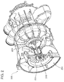
- Air cycle machine 200 in accordance with an exemplary embodiment of the invention shown.
- Air cycle machine 200 is substantially similar to air cycle machine 100 of FIG. 1 , and thus like features are labeled with the same reference numerals, except preceded by a "2" instead of a "1.”
- the air cycle machine 200 includes a fan 222 that is within a housing 220. Air enters the housing 220 at inlet 224 and apertures 218 and exits the housing 220, after passing the fan 222, at outlet 226.
- the apertures 218, as described above, provide or supply airflow that is used to cool bearings of the air cycle machine through the apertures 218 and into the housing 220 where the air will then pass the fan 222.
- the apertures are formed or machined either with an axis that is perpendicular to the surface of the housing (see, e.g., FIG. 4A , aperture 418a) or with an axis that is parallel to an axis of the air cycle machine (see, e.g., FIG. 1 , aperture 118).
- the apertures 218 are formed at an angle with respect to normal to the surface of the housing 220, and thus may be optimized for directing the airflow from the cooling process flow path (see airflow passage 106 in FIG. 1 ) toward the fan 222, and thus recover the energy from the bearing cooling process and increase system efficiency.
- the apertures 218 are formed within a portion of the housing, and particular, in the embodiment of FIG. 2 , within a ring 228.
- the ring 228 may form a nozzle that is configured to direct airflow by means of the apertures 218.
- the ring 228 may be installed into the housing 220.
- the ring 228 may be formed integrally with the housing 220, or in other alternative embodiments, the ring 228 may be omitted, and the apertures may be formed directly into and through the housing 220.
- the ring 228 is presented, as further described below with respect to FIGS. 5A-5C .
- the apertures may be formed by machining, drilling, casting, and/or by other means known in the art.
- Air cycle machine 300 is substantially similar to air cycle machines 100 and 200 of FIGS. 1 and 2 , respectively, and thus like features are labeled with the same reference numeral, except preceded by a "3" instead of a "1" or a "2.”
- the ring 328 is formed integral with the housing 320, as shown.
- the inlet 324 is shown along with a surface of the housing 320 and ring 328.
- the apertures 318 are formed as holes passing through a surface of the housing 320. As shown in FIG. 3 , there are five apertures 318. Those of skill in the art will appreciate that any number of apertures 318 may be formed in the housing 320 and/or ring 328, without departing from the scope of the invention.
- FIGS. 4A and 4B a comparison between a traditional configuration (4A) and an exemplary embodiment of the invention (4B) is shown.
- a wall of a housing 420a is shown.
- the housing 420a may be similar to the housing described above, wherein one or more apertures 418a may pass therethrough, allowing for air to pass from one side (bearing cooling side) to another side (fan side).
- An exemplary aperture 418a is shown with an aperture axis 432a defined by a central axis of the aperture 418a.
- a normal line 430a that is perpendicular or normal to the housing 420a. In this configuration, the aperture axis 432a is parallel with the normal line 430a.
- the aperture axis 432b of the aperture 418b is not parallel to the normal line 430b as it passes through the housing 420b.
- the aperture axis 432b is skew from the normal line 430b by an angle ⁇ .
- the air flow that passes through the aperture 418b may be optimized for impacting the fan that is inside the housing (such as shown in FIGS. 1-3 ).
- a plurality of apertures 418b may be formed at angle ⁇ , thus optimizing the amount of directed airflow that impacts the fan in the compressor.
- FIG. 5A is a top view of a ring 500 in accordance with an exemplary embodiment of the invention
- FIG. 5B is a cross-sectional view of the ring 500 along the line B-B of FIG. 5A
- FIG. 5C is a cross-sectional view of the ring 500 along the line C-C of FIG. 5A
- the ring 500 may be substantially similar to the ring 228 of FIG. 2 , and may form part of the housing, as described above.
- the ring 500 may be a sub-part, part of, or integrally formed with the housing.
- the ring is omitted and the apertures are formed directly in the housing (e.g., as shown in FIG. 1 ).
- a plurality of apertures 518 are formed through the ring 500.
- the apertures 518 are configured to optimize the airflow through the holes in a direction out of the page of FIG. 5 .
- the number of apertures 518 may be altered without departing from the scope of the invention.
- the cross-sectional view shows that the aperture 518 does not pass through the ring 500 normal to the surface of the ring, but rather at an angle, such that only a portion of the aperture 518 is shown in the cross-section of FIG. 5B .
- An axis 540 represents a central axis of the ring 500 and in some embodiments represents the axis of a machine in which the ring 500 is installed. As shown, a line 542 is parallel to the central axis 540. This is shown to indicate that the apertures 518 are not configured parallel to the axis of the machine, as is the case in some traditional configurations (e.g., as shown in FIG. 1 ). Similar to FIG. 4B , the apertures 518 are skew, and configured to optimize the airflow into the housing such that the airflow impacts a fan with a housing in an efficient manner.
- a partial cross-sectional view of the ring 500 is shown.
- angle ⁇ is the angle of skew of the aperture 518 with respect to a plane 544 defined by a portion of the ring 500.
- the plane 544 is a plane that is defined by a plurality of radii extending from the central axis 540. As will be understood by those of skill in the art, with respect to FIG. 5A , that the plane 544 is parallel to the page or paper of the figure.
- the aperture 518 may have a variable configuration.
- the aperture 518, of FIGS. 5A-5C has a first portion 550 and a second portion 552, wherein each portion 550, 552 defines a hollow cylinder through the ring 500.
- the portions 550, 552 run substantially parallel to the aperture axis 532 and are oriented at the angle ⁇ .
- the first portion 550 has a first diameter 551 and the second portion 552 has a second diameter 553.
- the change in diameter of the aperture 518 may be configured to further optimize the air flow as it passes through the aperture 518 and thus impact the fan most efficiently.
- the length of the two portions 550, 552 may be configured and/or optimized for the most efficient and directed airflow through the aperture 518.
- the aperture may have a constant diameter as it passes through the ring.
- the configuration may not be cylindrical about the aperture axis, but may be spiral, or any other configuration, that is designed to optimize the airflow out of the aperture and direct the flow toward the fan.
- embodiments of the invention provide an improved air cycle machine cooling flow path that enables energy recovery.
- Embodiments of the invention enable the recovery of waste stream energy, i.e., energy that is a result of air flow from a cooling airflow path in the air cycle machine.
- the airflow from the cooling flow of the air cycle machine may be about three percent of the total inflow that is directed toward a fan.
- energy recovery of this flow is enabled, thereby increasing the efficiency of the system as a whole.
- embodiments of the invention enable optimization of airflow as it is directed toward a fan of an air cycle machine, and thus augment the air already directed at the fan, thereby reducing the total energy required by the system.
- the various angles described herein may be any angles that are configured to optimally direct the flow of air as it passes through the apertures.
- the shape, size, dimensions, position, quantity, etc. of the apertures may be varied depending on the needs of the system, and to most appropriately optimize the air flow through the apertures and toward the fan.
Landscapes
- Engineering & Computer Science (AREA)
- General Engineering & Computer Science (AREA)
- Mechanical Engineering (AREA)
- Physics & Mathematics (AREA)
- Thermal Sciences (AREA)
- Life Sciences & Earth Sciences (AREA)
- Sustainable Development (AREA)
- Chemical & Material Sciences (AREA)
- Combustion & Propulsion (AREA)
- Structures Of Non-Positive Displacement Pumps (AREA)
Applications Claiming Priority (1)
| Application Number | Priority Date | Filing Date | Title |
|---|---|---|---|
| US14/668,016 US9897093B2 (en) | 2015-03-25 | 2015-03-25 | Bearing cooling flow and energy recovery systems |
Publications (2)
| Publication Number | Publication Date |
|---|---|
| EP3073121A1 true EP3073121A1 (de) | 2016-09-28 |
| EP3073121B1 EP3073121B1 (de) | 2020-01-01 |
Family
ID=55699383
Family Applications (1)
| Application Number | Title | Priority Date | Filing Date |
|---|---|---|---|
| EP16161696.6A Active EP3073121B1 (de) | 2015-03-25 | 2016-03-22 | Lagerkühlstrom und energierückgewinnungssysteme |
Country Status (2)
| Country | Link |
|---|---|
| US (1) | US9897093B2 (de) |
| EP (1) | EP3073121B1 (de) |
Cited By (4)
| Publication number | Priority date | Publication date | Assignee | Title |
|---|---|---|---|---|
| EP3508424A1 (de) * | 2018-01-05 | 2019-07-10 | Hamilton Sundstrand Corporation | Gebläse- und kompressorgehäuse für eine luftkreislaufmaschine |
| US10619650B2 (en) | 2016-05-06 | 2020-04-14 | Hamilton Sundstrand Corporation | Air cycle machine fan and compressor housing |
| US10661906B2 (en) | 2014-09-23 | 2020-05-26 | Hamilton Sundstrand Corporation | Fan and compressor housing for an air cycle machine |
| EP3708799A1 (de) * | 2019-03-15 | 2020-09-16 | Deere & Company | Lüfterhaube |
Families Citing this family (12)
| Publication number | Priority date | Publication date | Assignee | Title |
|---|---|---|---|---|
| WO2015130425A2 (en) * | 2014-02-03 | 2015-09-03 | United Technologies Corporation | Gas turbine engine cooling fluid composite tube |
| US9920708B2 (en) * | 2015-02-09 | 2018-03-20 | United Technologies Corporation | Nose cone assembly and method of circulating air in a gas turbine engine |
| US10060350B2 (en) * | 2015-04-13 | 2018-08-28 | United Technologies Corporation | Nose cone assembly and method of circulating air in a gas turbine engine |
| JP6546481B2 (ja) * | 2015-08-31 | 2019-07-17 | 川崎重工業株式会社 | 排気ディフューザ |
| US10215096B2 (en) * | 2015-11-04 | 2019-02-26 | United Technologies Corporation | Engine with nose cone heat exchanger and radially outer discharge |
| DE102016217320A1 (de) * | 2016-09-12 | 2018-03-15 | Siemens Aktiengesellschaft | Gasturbine mit getrennter Kühlung für Turbine und Abgasgehäuse |
| US10322621B2 (en) | 2017-02-15 | 2019-06-18 | Hamilton Sundstrand Corporation | Inertial particle separator for air cycle machine |
| US10668486B2 (en) | 2017-07-12 | 2020-06-02 | Hamilton Sundstrand Corporation | Water extractor |
| US10633099B2 (en) | 2018-03-12 | 2020-04-28 | Hamilton Sundstrand Corporation | Non-horizontal water extractor |
| JP6881645B1 (ja) * | 2020-03-31 | 2021-06-02 | ダイキン工業株式会社 | スラスト気体軸受、それを備える遠心型圧縮機、およびそれを備える冷凍装置 |
| US11655039B2 (en) | 2020-04-03 | 2023-05-23 | Hamilton Sundstrand Corporation | Turbine housing for a two wheel air cycle machine |
| US11761349B2 (en) | 2020-04-03 | 2023-09-19 | Hamilton Sundstrand Corporation | Bearing housing for a two-wheel air cycle machine |
Citations (3)
| Publication number | Priority date | Publication date | Assignee | Title |
|---|---|---|---|---|
| DE102009002416A1 (de) * | 2009-04-16 | 2010-10-21 | Robert Bosch Gmbh | Gebläsemodul |
| US20110229351A1 (en) * | 2010-03-22 | 2011-09-22 | Beers Craig M | Journal bearing with dual pass cooling for air machine |
| EP3020637A1 (de) * | 2014-11-13 | 2016-05-18 | Hamilton Sundstrand Corporation | Luftkreislaufmaschine mit lagerfehlererkennung |
Family Cites Families (2)
| Publication number | Priority date | Publication date | Assignee | Title |
|---|---|---|---|---|
| US5059093A (en) * | 1990-06-07 | 1991-10-22 | United Technologies Corporation | Compressor bleed port |
| US5309735A (en) * | 1991-09-11 | 1994-05-10 | United Technologies Corporation | Four wheel air cycle machine |
-
2015
- 2015-03-25 US US14/668,016 patent/US9897093B2/en active Active
-
2016
- 2016-03-22 EP EP16161696.6A patent/EP3073121B1/de active Active
Patent Citations (3)
| Publication number | Priority date | Publication date | Assignee | Title |
|---|---|---|---|---|
| DE102009002416A1 (de) * | 2009-04-16 | 2010-10-21 | Robert Bosch Gmbh | Gebläsemodul |
| US20110229351A1 (en) * | 2010-03-22 | 2011-09-22 | Beers Craig M | Journal bearing with dual pass cooling for air machine |
| EP3020637A1 (de) * | 2014-11-13 | 2016-05-18 | Hamilton Sundstrand Corporation | Luftkreislaufmaschine mit lagerfehlererkennung |
Cited By (7)
| Publication number | Priority date | Publication date | Assignee | Title |
|---|---|---|---|---|
| US10661906B2 (en) | 2014-09-23 | 2020-05-26 | Hamilton Sundstrand Corporation | Fan and compressor housing for an air cycle machine |
| US10619650B2 (en) | 2016-05-06 | 2020-04-14 | Hamilton Sundstrand Corporation | Air cycle machine fan and compressor housing |
| EP3508424A1 (de) * | 2018-01-05 | 2019-07-10 | Hamilton Sundstrand Corporation | Gebläse- und kompressorgehäuse für eine luftkreislaufmaschine |
| US10788046B2 (en) | 2018-01-05 | 2020-09-29 | Hamilton Sundstrand Corporation | Fan and compressor housing for an air cycle machine |
| EP3708799A1 (de) * | 2019-03-15 | 2020-09-16 | Deere & Company | Lüfterhaube |
| US10947991B2 (en) | 2019-03-15 | 2021-03-16 | Deere & Company | Fan shroud |
| EP4006320A1 (de) * | 2019-03-15 | 2022-06-01 | Deere & Company | Lüfterhaube |
Also Published As
| Publication number | Publication date |
|---|---|
| EP3073121B1 (de) | 2020-01-01 |
| US20160281721A1 (en) | 2016-09-29 |
| US9897093B2 (en) | 2018-02-20 |
Similar Documents
| Publication | Publication Date | Title |
|---|---|---|
| EP3073121B1 (de) | Lagerkühlstrom und energierückgewinnungssysteme | |
| US8459966B2 (en) | Ram air fan motor cooling | |
| US20130129488A1 (en) | Foil bearing supported motor-driven blower | |
| US9470234B2 (en) | Compressor housing bearing and seal | |
| US9989070B2 (en) | Air cycle machine strut plate assembly | |
| US10975887B2 (en) | Rotary machine heat sink | |
| CN106246241B (zh) | 涡轮机密封板 | |
| US9393652B2 (en) | Turbine housing | |
| US11359498B2 (en) | Turbine engine airfoil assembly | |
| US8376690B2 (en) | Three bearing flexible shaft for high speed turbomachinery | |
| US20150037138A1 (en) | Thrust shaft for ram air fan | |
| CN106837434B (zh) | 用于空气轴承冷却的涡轮机推力轴 | |
| US9651091B2 (en) | Thrust plate assembly | |
| EP2647801B1 (de) | Lagerkühlsystem für Turbomaschine mit flexibler Welle | |
| US20170102002A1 (en) | Fan shaft for air cycle machine | |
| EP3550149B1 (de) | Strukturell verbesserte stauluftgebläse-einlassabdeckung | |
| US20160186577A1 (en) | Cooling configurations for turbine blades | |
| US10787270B2 (en) | Propulsor |
Legal Events
| Date | Code | Title | Description |
|---|---|---|---|
| PUAI | Public reference made under article 153(3) epc to a published international application that has entered the european phase |
Free format text: ORIGINAL CODE: 0009012 |
|
| AK | Designated contracting states |
Kind code of ref document: A1 Designated state(s): AL AT BE BG CH CY CZ DE DK EE ES FI FR GB GR HR HU IE IS IT LI LT LU LV MC MK MT NL NO PL PT RO RS SE SI SK SM TR |
|
| AX | Request for extension of the european patent |
Extension state: BA ME |
|
| RIN1 | Information on inventor provided before grant (corrected) |
Inventor name: ARMY, DONALD E. Inventor name: MC AULIFFE, CHRISTOPHER Inventor name: HIPSKY, HAROLD W. |
|
| STAA | Information on the status of an ep patent application or granted ep patent |
Free format text: STATUS: REQUEST FOR EXAMINATION WAS MADE |
|
| 17P | Request for examination filed |
Effective date: 20170327 |
|
| RBV | Designated contracting states (corrected) |
Designated state(s): AL AT BE BG CH CY CZ DE DK EE ES FI FR GB GR HR HU IE IS IT LI LT LU LV MC MK MT NL NO PL PT RO RS SE SI SK SM TR |
|
| GRAP | Despatch of communication of intention to grant a patent |
Free format text: ORIGINAL CODE: EPIDOSNIGR1 |
|
| STAA | Information on the status of an ep patent application or granted ep patent |
Free format text: STATUS: GRANT OF PATENT IS INTENDED |
|
| INTG | Intention to grant announced |
Effective date: 20190719 |
|
| RAP1 | Party data changed (applicant data changed or rights of an application transferred) |
Owner name: HAMILTON SUNDSTRAND CORPORATION |
|
| GRAS | Grant fee paid |
Free format text: ORIGINAL CODE: EPIDOSNIGR3 |
|
| GRAA | (expected) grant |
Free format text: ORIGINAL CODE: 0009210 |
|
| STAA | Information on the status of an ep patent application or granted ep patent |
Free format text: STATUS: THE PATENT HAS BEEN GRANTED |
|
| AK | Designated contracting states |
Kind code of ref document: B1 Designated state(s): AL AT BE BG CH CY CZ DE DK EE ES FI FR GB GR HR HU IE IS IT LI LT LU LV MC MK MT NL NO PL PT RO RS SE SI SK SM TR |
|
| REG | Reference to a national code |
Ref country code: GB Ref legal event code: FG4D |
|
| REG | Reference to a national code |
Ref country code: CH Ref legal event code: EP Ref country code: AT Ref legal event code: REF Ref document number: 1220099 Country of ref document: AT Kind code of ref document: T Effective date: 20200115 |
|
| REG | Reference to a national code |
Ref country code: IE Ref legal event code: FG4D |
|
| REG | Reference to a national code |
Ref country code: DE Ref legal event code: R096 Ref document number: 602016027138 Country of ref document: DE |
|
| REG | Reference to a national code |
Ref country code: NL Ref legal event code: MP Effective date: 20200101 |
|
| REG | Reference to a national code |
Ref country code: LT Ref legal event code: MG4D |
|
| PG25 | Lapsed in a contracting state [announced via postgrant information from national office to epo] |
Ref country code: RS Free format text: LAPSE BECAUSE OF FAILURE TO SUBMIT A TRANSLATION OF THE DESCRIPTION OR TO PAY THE FEE WITHIN THE PRESCRIBED TIME-LIMIT Effective date: 20200101 Ref country code: FI Free format text: LAPSE BECAUSE OF FAILURE TO SUBMIT A TRANSLATION OF THE DESCRIPTION OR TO PAY THE FEE WITHIN THE PRESCRIBED TIME-LIMIT Effective date: 20200101 Ref country code: NO Free format text: LAPSE BECAUSE OF FAILURE TO SUBMIT A TRANSLATION OF THE DESCRIPTION OR TO PAY THE FEE WITHIN THE PRESCRIBED TIME-LIMIT Effective date: 20200401 Ref country code: LT Free format text: LAPSE BECAUSE OF FAILURE TO SUBMIT A TRANSLATION OF THE DESCRIPTION OR TO PAY THE FEE WITHIN THE PRESCRIBED TIME-LIMIT Effective date: 20200101 Ref country code: NL Free format text: LAPSE BECAUSE OF FAILURE TO SUBMIT A TRANSLATION OF THE DESCRIPTION OR TO PAY THE FEE WITHIN THE PRESCRIBED TIME-LIMIT Effective date: 20200101 Ref country code: PT Free format text: LAPSE BECAUSE OF FAILURE TO SUBMIT A TRANSLATION OF THE DESCRIPTION OR TO PAY THE FEE WITHIN THE PRESCRIBED TIME-LIMIT Effective date: 20200527 Ref country code: CZ Free format text: LAPSE BECAUSE OF FAILURE TO SUBMIT A TRANSLATION OF THE DESCRIPTION OR TO PAY THE FEE WITHIN THE PRESCRIBED TIME-LIMIT Effective date: 20200101 |
|
| PG25 | Lapsed in a contracting state [announced via postgrant information from national office to epo] |
Ref country code: IS Free format text: LAPSE BECAUSE OF FAILURE TO SUBMIT A TRANSLATION OF THE DESCRIPTION OR TO PAY THE FEE WITHIN THE PRESCRIBED TIME-LIMIT Effective date: 20200501 Ref country code: LV Free format text: LAPSE BECAUSE OF FAILURE TO SUBMIT A TRANSLATION OF THE DESCRIPTION OR TO PAY THE FEE WITHIN THE PRESCRIBED TIME-LIMIT Effective date: 20200101 Ref country code: SE Free format text: LAPSE BECAUSE OF FAILURE TO SUBMIT A TRANSLATION OF THE DESCRIPTION OR TO PAY THE FEE WITHIN THE PRESCRIBED TIME-LIMIT Effective date: 20200101 Ref country code: GR Free format text: LAPSE BECAUSE OF FAILURE TO SUBMIT A TRANSLATION OF THE DESCRIPTION OR TO PAY THE FEE WITHIN THE PRESCRIBED TIME-LIMIT Effective date: 20200402 Ref country code: BG Free format text: LAPSE BECAUSE OF FAILURE TO SUBMIT A TRANSLATION OF THE DESCRIPTION OR TO PAY THE FEE WITHIN THE PRESCRIBED TIME-LIMIT Effective date: 20200401 Ref country code: HR Free format text: LAPSE BECAUSE OF FAILURE TO SUBMIT A TRANSLATION OF THE DESCRIPTION OR TO PAY THE FEE WITHIN THE PRESCRIBED TIME-LIMIT Effective date: 20200101 |
|
| REG | Reference to a national code |
Ref country code: DE Ref legal event code: R119 Ref document number: 602016027138 Country of ref document: DE |
|
| PG25 | Lapsed in a contracting state [announced via postgrant information from national office to epo] |
Ref country code: SM Free format text: LAPSE BECAUSE OF FAILURE TO SUBMIT A TRANSLATION OF THE DESCRIPTION OR TO PAY THE FEE WITHIN THE PRESCRIBED TIME-LIMIT Effective date: 20200101 Ref country code: SK Free format text: LAPSE BECAUSE OF FAILURE TO SUBMIT A TRANSLATION OF THE DESCRIPTION OR TO PAY THE FEE WITHIN THE PRESCRIBED TIME-LIMIT Effective date: 20200101 Ref country code: MC Free format text: LAPSE BECAUSE OF FAILURE TO SUBMIT A TRANSLATION OF THE DESCRIPTION OR TO PAY THE FEE WITHIN THE PRESCRIBED TIME-LIMIT Effective date: 20200101 Ref country code: ES Free format text: LAPSE BECAUSE OF FAILURE TO SUBMIT A TRANSLATION OF THE DESCRIPTION OR TO PAY THE FEE WITHIN THE PRESCRIBED TIME-LIMIT Effective date: 20200101 Ref country code: RO Free format text: LAPSE BECAUSE OF FAILURE TO SUBMIT A TRANSLATION OF THE DESCRIPTION OR TO PAY THE FEE WITHIN THE PRESCRIBED TIME-LIMIT Effective date: 20200101 Ref country code: DK Free format text: LAPSE BECAUSE OF FAILURE TO SUBMIT A TRANSLATION OF THE DESCRIPTION OR TO PAY THE FEE WITHIN THE PRESCRIBED TIME-LIMIT Effective date: 20200101 Ref country code: EE Free format text: LAPSE BECAUSE OF FAILURE TO SUBMIT A TRANSLATION OF THE DESCRIPTION OR TO PAY THE FEE WITHIN THE PRESCRIBED TIME-LIMIT Effective date: 20200101 |
|
| REG | Reference to a national code |
Ref country code: CH Ref legal event code: PL |
|
| PLBE | No opposition filed within time limit |
Free format text: ORIGINAL CODE: 0009261 |
|
| STAA | Information on the status of an ep patent application or granted ep patent |
Free format text: STATUS: NO OPPOSITION FILED WITHIN TIME LIMIT |
|
| REG | Reference to a national code |
Ref country code: AT Ref legal event code: MK05 Ref document number: 1220099 Country of ref document: AT Kind code of ref document: T Effective date: 20200101 |
|
| 26N | No opposition filed |
Effective date: 20201002 |
|
| REG | Reference to a national code |
Ref country code: BE Ref legal event code: MM Effective date: 20200331 |
|
| PG25 | Lapsed in a contracting state [announced via postgrant information from national office to epo] |
Ref country code: LU Free format text: LAPSE BECAUSE OF NON-PAYMENT OF DUE FEES Effective date: 20200322 |
|
| PG25 | Lapsed in a contracting state [announced via postgrant information from national office to epo] |
Ref country code: CH Free format text: LAPSE BECAUSE OF NON-PAYMENT OF DUE FEES Effective date: 20200331 Ref country code: IE Free format text: LAPSE BECAUSE OF NON-PAYMENT OF DUE FEES Effective date: 20200322 Ref country code: LI Free format text: LAPSE BECAUSE OF NON-PAYMENT OF DUE FEES Effective date: 20200331 Ref country code: DE Free format text: LAPSE BECAUSE OF NON-PAYMENT OF DUE FEES Effective date: 20201001 Ref country code: AT Free format text: LAPSE BECAUSE OF FAILURE TO SUBMIT A TRANSLATION OF THE DESCRIPTION OR TO PAY THE FEE WITHIN THE PRESCRIBED TIME-LIMIT Effective date: 20200101 Ref country code: IT Free format text: LAPSE BECAUSE OF FAILURE TO SUBMIT A TRANSLATION OF THE DESCRIPTION OR TO PAY THE FEE WITHIN THE PRESCRIBED TIME-LIMIT Effective date: 20200101 |
|
| PG25 | Lapsed in a contracting state [announced via postgrant information from national office to epo] |
Ref country code: SI Free format text: LAPSE BECAUSE OF FAILURE TO SUBMIT A TRANSLATION OF THE DESCRIPTION OR TO PAY THE FEE WITHIN THE PRESCRIBED TIME-LIMIT Effective date: 20200101 Ref country code: PL Free format text: LAPSE BECAUSE OF FAILURE TO SUBMIT A TRANSLATION OF THE DESCRIPTION OR TO PAY THE FEE WITHIN THE PRESCRIBED TIME-LIMIT Effective date: 20200101 Ref country code: BE Free format text: LAPSE BECAUSE OF NON-PAYMENT OF DUE FEES Effective date: 20200331 |
|
| PG25 | Lapsed in a contracting state [announced via postgrant information from national office to epo] |
Ref country code: TR Free format text: LAPSE BECAUSE OF FAILURE TO SUBMIT A TRANSLATION OF THE DESCRIPTION OR TO PAY THE FEE WITHIN THE PRESCRIBED TIME-LIMIT Effective date: 20200101 Ref country code: MT Free format text: LAPSE BECAUSE OF FAILURE TO SUBMIT A TRANSLATION OF THE DESCRIPTION OR TO PAY THE FEE WITHIN THE PRESCRIBED TIME-LIMIT Effective date: 20200101 Ref country code: CY Free format text: LAPSE BECAUSE OF FAILURE TO SUBMIT A TRANSLATION OF THE DESCRIPTION OR TO PAY THE FEE WITHIN THE PRESCRIBED TIME-LIMIT Effective date: 20200101 |
|
| PG25 | Lapsed in a contracting state [announced via postgrant information from national office to epo] |
Ref country code: MK Free format text: LAPSE BECAUSE OF FAILURE TO SUBMIT A TRANSLATION OF THE DESCRIPTION OR TO PAY THE FEE WITHIN THE PRESCRIBED TIME-LIMIT Effective date: 20200101 Ref country code: AL Free format text: LAPSE BECAUSE OF FAILURE TO SUBMIT A TRANSLATION OF THE DESCRIPTION OR TO PAY THE FEE WITHIN THE PRESCRIBED TIME-LIMIT Effective date: 20200101 |
|
| PGFP | Annual fee paid to national office [announced via postgrant information from national office to epo] |
Ref country code: FR Payment date: 20230222 Year of fee payment: 8 |
|
| P01 | Opt-out of the competence of the unified patent court (upc) registered |
Effective date: 20230522 |
|
| PGFP | Annual fee paid to national office [announced via postgrant information from national office to epo] |
Ref country code: GB Payment date: 20240220 Year of fee payment: 9 |