EP3072789A1 - Machine tool with walking apparatus - Google Patents
Machine tool with walking apparatus Download PDFInfo
- Publication number
- EP3072789A1 EP3072789A1 EP16160582.9A EP16160582A EP3072789A1 EP 3072789 A1 EP3072789 A1 EP 3072789A1 EP 16160582 A EP16160582 A EP 16160582A EP 3072789 A1 EP3072789 A1 EP 3072789A1
- Authority
- EP
- European Patent Office
- Prior art keywords
- leg
- machine tool
- legs
- actuator
- actuators
- Prior art date
- Legal status (The legal status is an assumption and is not a legal conclusion. Google has not performed a legal analysis and makes no representation as to the accuracy of the status listed.)
- Granted
Links
Images


Classifications
-
- B—PERFORMING OPERATIONS; TRANSPORTING
- B23—MACHINE TOOLS; METAL-WORKING NOT OTHERWISE PROVIDED FOR
- B23Q—DETAILS, COMPONENTS, OR ACCESSORIES FOR MACHINE TOOLS, e.g. ARRANGEMENTS FOR COPYING OR CONTROLLING; MACHINE TOOLS IN GENERAL CHARACTERISED BY THE CONSTRUCTION OF PARTICULAR DETAILS OR COMPONENTS; COMBINATIONS OR ASSOCIATIONS OF METAL-WORKING MACHINES, NOT DIRECTED TO A PARTICULAR RESULT
- B23Q1/00—Members which are comprised in the general build-up of a form of machine, particularly relatively large fixed members
- B23Q1/25—Movable or adjustable work or tool supports
- B23Q1/44—Movable or adjustable work or tool supports using particular mechanisms
- B23Q1/48—Movable or adjustable work or tool supports using particular mechanisms with sliding pairs and rotating pairs
-
- B—PERFORMING OPERATIONS; TRANSPORTING
- B23—MACHINE TOOLS; METAL-WORKING NOT OTHERWISE PROVIDED FOR
- B23Q—DETAILS, COMPONENTS, OR ACCESSORIES FOR MACHINE TOOLS, e.g. ARRANGEMENTS FOR COPYING OR CONTROLLING; MACHINE TOOLS IN GENERAL CHARACTERISED BY THE CONSTRUCTION OF PARTICULAR DETAILS OR COMPONENTS; COMBINATIONS OR ASSOCIATIONS OF METAL-WORKING MACHINES, NOT DIRECTED TO A PARTICULAR RESULT
- B23Q1/00—Members which are comprised in the general build-up of a form of machine, particularly relatively large fixed members
- B23Q1/25—Movable or adjustable work or tool supports
- B23Q1/44—Movable or adjustable work or tool supports using particular mechanisms
- B23Q1/50—Movable or adjustable work or tool supports using particular mechanisms with rotating pairs only, the rotating pairs being the first two elements of the mechanism
- B23Q1/54—Movable or adjustable work or tool supports using particular mechanisms with rotating pairs only, the rotating pairs being the first two elements of the mechanism two rotating pairs only
- B23Q1/545—Movable or adjustable work or tool supports using particular mechanisms with rotating pairs only, the rotating pairs being the first two elements of the mechanism two rotating pairs only comprising spherical surfaces
- B23Q1/5462—Movable or adjustable work or tool supports using particular mechanisms with rotating pairs only, the rotating pairs being the first two elements of the mechanism two rotating pairs only comprising spherical surfaces with one supplementary sliding pair
-
- B—PERFORMING OPERATIONS; TRANSPORTING
- B23—MACHINE TOOLS; METAL-WORKING NOT OTHERWISE PROVIDED FOR
- B23Q—DETAILS, COMPONENTS, OR ACCESSORIES FOR MACHINE TOOLS, e.g. ARRANGEMENTS FOR COPYING OR CONTROLLING; MACHINE TOOLS IN GENERAL CHARACTERISED BY THE CONSTRUCTION OF PARTICULAR DETAILS OR COMPONENTS; COMBINATIONS OR ASSOCIATIONS OF METAL-WORKING MACHINES, NOT DIRECTED TO A PARTICULAR RESULT
- B23Q9/00—Arrangements for supporting or guiding portable metal-working machines or apparatus
- B23Q9/0007—Portable machines comprising means for their guidance or support directly on the workpiece
-
- B—PERFORMING OPERATIONS; TRANSPORTING
- B23—MACHINE TOOLS; METAL-WORKING NOT OTHERWISE PROVIDED FOR
- B23Q—DETAILS, COMPONENTS, OR ACCESSORIES FOR MACHINE TOOLS, e.g. ARRANGEMENTS FOR COPYING OR CONTROLLING; MACHINE TOOLS IN GENERAL CHARACTERISED BY THE CONSTRUCTION OF PARTICULAR DETAILS OR COMPONENTS; COMBINATIONS OR ASSOCIATIONS OF METAL-WORKING MACHINES, NOT DIRECTED TO A PARTICULAR RESULT
- B23Q9/00—Arrangements for supporting or guiding portable metal-working machines or apparatus
- B23Q9/0014—Portable machines provided with or cooperating with guide means supported directly by the workpiece during action
-
- B—PERFORMING OPERATIONS; TRANSPORTING
- B25—HAND TOOLS; PORTABLE POWER-DRIVEN TOOLS; MANIPULATORS
- B25H—WORKSHOP EQUIPMENT, e.g. FOR MARKING-OUT WORK; STORAGE MEANS FOR WORKSHOPS
- B25H1/00—Work benches; Portable stands or supports for positioning portable tools or work to be operated on thereby
- B25H1/0021—Stands, supports or guiding devices for positioning portable tools or for securing them to the work
- B25H1/0042—Stands
-
- B—PERFORMING OPERATIONS; TRANSPORTING
- B25—HAND TOOLS; PORTABLE POWER-DRIVEN TOOLS; MANIPULATORS
- B25J—MANIPULATORS; CHAMBERS PROVIDED WITH MANIPULATION DEVICES
- B25J9/00—Programme-controlled manipulators
- B25J9/003—Programme-controlled manipulators having parallel kinematics
- B25J9/0054—Programme-controlled manipulators having parallel kinematics with kinematics chains having a spherical joint at the base
- B25J9/0057—Programme-controlled manipulators having parallel kinematics with kinematics chains having a spherical joint at the base with kinematics chains of the type spherical-prismatic-spherical
-
- B—PERFORMING OPERATIONS; TRANSPORTING
- B62—LAND VEHICLES FOR TRAVELLING OTHERWISE THAN ON RAILS
- B62D—MOTOR VEHICLES; TRAILERS
- B62D57/00—Vehicles characterised by having other propulsion or other ground- engaging means than wheels or endless track, alone or in addition to wheels or endless track
- B62D57/02—Vehicles characterised by having other propulsion or other ground- engaging means than wheels or endless track, alone or in addition to wheels or endless track with ground-engaging propulsion means, e.g. walking members
- B62D57/032—Vehicles characterised by having other propulsion or other ground- engaging means than wheels or endless track, alone or in addition to wheels or endless track with ground-engaging propulsion means, e.g. walking members with alternately or sequentially lifted supporting base and legs; with alternately or sequentially lifted feet or skid
-
- G—PHYSICS
- G05—CONTROLLING; REGULATING
- G05B—CONTROL OR REGULATING SYSTEMS IN GENERAL; FUNCTIONAL ELEMENTS OF SUCH SYSTEMS; MONITORING OR TESTING ARRANGEMENTS FOR SUCH SYSTEMS OR ELEMENTS
- G05B19/00—Programme-control systems
- G05B19/02—Programme-control systems electric
- G05B19/18—Numerical control [NC], i.e. automatically operating machines, in particular machine tools, e.g. in a manufacturing environment, so as to execute positioning, movement or co-ordinated operations by means of programme data in numerical form
- G05B19/19—Numerical control [NC], i.e. automatically operating machines, in particular machine tools, e.g. in a manufacturing environment, so as to execute positioning, movement or co-ordinated operations by means of programme data in numerical form characterised by positioning or contouring control systems, e.g. to control position from one programmed point to another or to control movement along a programmed continuous path
-
- G—PHYSICS
- G05—CONTROLLING; REGULATING
- G05B—CONTROL OR REGULATING SYSTEMS IN GENERAL; FUNCTIONAL ELEMENTS OF SUCH SYSTEMS; MONITORING OR TESTING ARRANGEMENTS FOR SUCH SYSTEMS OR ELEMENTS
- G05B2219/00—Program-control systems
- G05B2219/30—Nc systems
- G05B2219/49—Nc machine tool, till multiple
- G05B2219/49361—Workpiece and tool have each own rotation speed
Definitions
- the present disclosure concerns machine tools, methods of controlling machine tools, and apparatus to control machine tools.
- Machine tools such as Stewart platforms, may be used to machine an object in an industrial environment.
- a machine tool may be used in many different systems, across a wide range of technologies, for example in nuclear engineering, aircraft, gas turbine engines, industrial plants, shipbuilding, buildings, roads and pipelines.
- the environment may be hazardous (such as in nuclear engineering) and/or include confined spaces (such as in a gas turbine engine). In such systems, it may be challenging and/or dangerous for a human operator to position a machining tool at a desired location to machine and/or inspect a desired object.
- a machine tool comprising: a first body; a first leg, a second leg, and a third leg coupled to the first body via first joints and configured to support at least the first body; a second body including a tool holder; a fourth leg, a fifth leg, and a sixth leg coupled to the second body via second joints and configured to support at least the second body; and a first actuator coupled to the first body and to the second body, the first actuator being configured to cause rotational motion between the first body and the second body to enable a change in walking direction of the machine tool and/or to enable a change in machining stiffness and a change in work volume of the machine tool.
- the first body may have a first axis and the second body may have a second axis.
- the first axis and the second axis may be offset relative to one another so that the first body and the second body are eccentric.
- the first body may have a first axis and the second body may have a second axis.
- the first axis and the second axis may define a common centre of the first body and the second body so that the first body and the second body are concentric.
- the first actuator may be configured to cause rotational motion between the first body and the second body while the first leg, the second leg, the third leg, the fourth leg, the fifth leg and the sixth leg contact a surface to change the machining stiffness of the machine tool.
- the first leg, the second leg, the third leg, the fourth leg, the fifth leg, and the sixth leg may each comprise: a second actuator and a prismatic joint, the second actuators may be configured to move the respective legs between an extended state and a retracted state at their respective prismatic joints.
- the fourth leg, the fifth leg, and the sixth leg may be configured to support the machine tool while in the extended state and while the first leg, the second leg and the third leg are in the retracted state, to enable the first actuator to cause rotational motion between the first body and the second body to enable a change in walking direction of the machine tool.
- the first leg, the second leg and the third leg may each comprise a third actuator.
- the third actuators may be configured to pivot the respective first, second and third legs about their respective first joints to enable the machine tool to walk.
- the second leg and the third leg may be configured to rotate relative to the first body.
- the machine tool may comprise a fourth actuator to rotate the second and third legs to change the state of the machine tool between a walking state and a machining state.
- the second body may include a first cylindrical protrusion and the first actuator may comprise a gear positioned adjacent to the first cylindrical protrusion.
- the first body may define a cavity therein for receiving the first cylindrical protrusion and the gear.
- the first body may include a plurality of teeth within the cavity for engaging the gear of the first actuator.
- the second body may include a second cylindrical protrusion positioned within the first cylindrical protrusion.
- the second cylindrical protrusion may be eccentric with the second axis of the second body and with the first cylindrical protrusion.
- the second cylindrical protrusion may be coupled to the tool holder.
- the tool holder may be eccentric with the second cylindrical protrusion.
- a method of controlling a machine tool as described in any of the preceding paragraphs, the method comprising: receiving a signal from a user input device and/or from a sensor; and controlling the first actuator, using the received signal, to cause rotational motion between the first body and the second body.
- the first leg, the second leg, the third leg, the fourth leg, the fifth leg, and the sixth leg may each comprise: a second actuator and a prismatic joint.
- the method may further comprise controlling the second actuators of the first, second, and third legs or the second actuators of the fourth, fifth, and sixth legs, to move the respective legs between an extended state and a retracted state at their respective prismatic joints.
- the first leg, the second leg and the third leg may each comprise a third actuator.
- the method may further comprise controlling the third actuators to pivot the respective first, second and third legs about their respective first joints to enable the machine tool to walk.
- the second leg and the third leg may be configured to rotate relative to the first body and the machine tool may further comprise a fourth actuator for rotating the second and third legs relative to the first body.
- the method may further comprise controlling the fourth actuator to rotate the second and third legs to change the state of the machine tool between a walking state and a machining state.
- a non-transitory computer readable storage medium comprising computer readable instructions that, when read by a computer, causes performance of the method as described in any of the preceding paragraphs.
- apparatus to control a machine tool comprising: a controller to perform the method as described in any of the preceding paragraphs.
- Fig. 1 illustrates a schematic diagram of a machine tool 10 including a first body 12, a second body 14 including a tool holder 16, a first leg 18, a second leg 20, a third leg 22, a plurality of first joints 24, a fourth leg 26, a fifth leg 28, a sixth leg 30, a plurality of second joints 32, and a first actuator 34.
- the first body 12 may have any suitable shape and dimensions and defines a first axis 36.
- the second body 14 may have any suitable shape and dimensions and defines a second axis 38.
- the first axis 36 and the second axis 38 define a common centre of the first body 12 and the second body 14 so that the first body 12 and the second body 14 are concentric.
- the first axis 36 and the second axis 38 are offset relative to one another so that the first body 12 and the second body 14 are eccentric.
- the first leg 18, the second leg 20, and the third leg 22 are coupled to the first body 12 via the plurality of first joints 24 and are configured to support at least the first body 12.
- the fourth leg 26, the fifth leg 28, and the sixth leg 30 are coupled to the second body 14 via second joints 32 and are configured to support at least the second body 14.
- the tool holder 16 is configured to receive one or more tools to enable the machine tool 10 to machine an object.
- the tool holder 16 may be configured to receive one or more of: a blending tool, a drill, a laser cutting tool, an imaging sensor (for example, a charge coupled device camera), a Raman spectrometer, a fluorescent penetrant applicator, and an ultraviolet (UV) inspection device and so on.
- a blending tool for example, a drill, a laser cutting tool, an imaging sensor (for example, a charge coupled device camera), a Raman spectrometer, a fluorescent penetrant applicator, and an ultraviolet (UV) inspection device and so on.
- a blending tool for example, a drill, a laser cutting tool, an imaging sensor (for example, a charge coupled device camera), a Raman spectrometer, a fluorescent penetrant applicator, and an ultraviolet (UV) inspection device and so on.
- an imaging sensor for example, a charge coupled device camera
- Raman spectrometer
- the first actuator 34 is coupled to the first body 12 and to the second body 14.
- the first actuator 34 is configured to cause rotational motion between the first body 12 and the second body 14 to enable a change in walking direction of the machine tool 10 and/or to enable a change in machining stiffness of the machine tool 10 and a change in the work volume of the machine tool 10 (that is, a change in the volume of space that the tool within the tool holder 16 may move through).
- the first actuator 34 may comprise any suitable apparatus or device for rotating the first body 12 and the second body 14 relative to one another.
- the first actuator 34 may comprise a servomotor (such as a pie motor), a pneumatic actuator, a hydraulic actuator, an electric linear motor.
- the first actuator 34 may be mounted eccentric to the first axis 36 and is arranged to provide rotational movement around its own axis.
- FIGs. 2A and 7 illustrate perspective views of a first part 40 of another machine tool 101 (as illustrated in Fig. 3 ).
- the machine tool 101 is similar to the machine tool 10 illustrated in Fig. 1 and where the features are similar, the same reference numerals are used.
- the first part 40 of the machine tool 101 includes the first body 12, the first leg 18, the second leg 20, and the third leg 22.
- the first part 40 may be module of the machine tool 101.
- the wording 'module' refers to a device or apparatus where one or more features are included at a later time, and possibly, by another manufacturer or by an end user.
- the machine tool 101 may be assembled by a different manufacturer to the manufacturer of the first part 40.
- the first body 12 (which may also be referred to as the first platform) has a triangular shape and defines a cavity 42 therein.
- the cavity 42 extends through the first body 12 and is positioned at the centre of the first body 12.
- the first body 12 includes a plurality of teeth 44 within the cavity 42.
- the first leg 18, the second leg 20 and the third leg 22 each comprise an upper part 46, a lower part 48, and a foot part 50.
- the upper part 46 and the lower part 48 are telescopically arranged and form a prismatic joint 52.
- the foot part 50 is coupled to the lower part 48 via a spherical joint 54 and may include apparatus for securing the foot part 50 to a surface (for example, the foot part 50 may include an air pump to enable the foot part 50 to form a vacuum with the surface to secure the machine tool 101 to the surface).
- the foot part 50 may include an electromagnet to enable the foot part to attach to the surface to secure the machine tool 101 to the surface.
- the first leg 18, the second leg 20 and the third leg 22 each comprise a second actuator 56 that is configured to move the respective leg between an extended state and a retracted state at their respective prismatic joints 52.
- the second actuator 56 may comprise a servomotor that is configured to control the telescopic movement of the lower part 48 and the upper part 46 to move the leg 18, 20, 22 between the extended state and the retracted state.
- the first leg 18, the second leg 20 and the third leg 22 each comprise a third actuator 58 that is configured to pivot the first, second and third legs 18, 20, 22 about their respective first joints 24 to enable the machine tool 101 to walk.
- the third actuator 58 includes a first servomotor 60, a second servomotor 62, a first screw 64 coupled to the first servomotor 60, a second screw 66 coupled to the second servomotor 62, a first cable anchor 68, a second cable anchor 69, a first pair of cables 70 coupled to the first cable anchor 68 and to the first body 12, and a second pair of cables 71 coupled to the second cable anchor 69 and to the first body 12.
- the first servomotor 60 is configured to rotate the first screw 64 to move the first cable anchor 68 up and down (as indicated by arrow 72) to provide and release tension in the first pair of cables 70.
- the second servomotor 62 is configured to rotate the second screw 66 to move the second cable anchor 69 up and down (as indicated by arrow 73) to provide and release tension in the second pair of cables 71.
- the leg pivots about the first joint 24 in the direction of arrow 74.
- the leg pivots about the first joint 24 in the direction of arrow 76. Consequently, the first joint 24 (which is a spherical joint on its own) and the third actuator 58 may form a revolute joint having a single degree of freedom. It should be appreciated that where the first pair and second pair of cables 70, 71 are slack, the first joint 24 forms a spherical joint having three degrees of freedom.
- the second leg 20 and the third leg 22 are configured to rotate relative to the first body 12 and the first part 40 comprises a fourth actuator 78 to rotate the second and third legs 20, 22 to change the state of the machine tool 101 between a walking state and a machining state.
- the fourth actuator 78 may include a motor and a gear system that meshes with gearing on the second and third legs 20, 22 to rotate the second and third legs 20, 22 in the directions of arrows 80 (that is, rotation about the longitudinal axes of the second and third legs 20, 22).
- Fig. 2B illustrates a perspective view of a second part 82 of the machine tool 101 (as illustrated in Fig. 3 ).
- the second part 82 of the machine tool 101 includes the second body 14, the fourth leg 26, the fifth leg 28, and the sixth leg 30.
- the second part 82 may be module of the machine tool 101.
- the machine tool 101 may be assembled by a different manufacturer to the manufacturer of the second part 82.
- the second body 14 (which may also be referred to as the second platform) has a triangular shape and includes a first cylindrical protrusion 84 and a second cylindrical protrusion 91 positioned within the first cylindrical protrusion 84.
- the first actuator 14 comprises a gear 86 that is positioned adjacent to the first cylindrical protrusion 84 and a servomotor 88 for rotating the gear 86.
- the first cylindrical protrusion 84 and the gear 86 may be received within the cavity 42 of the first body 12 so that the gear 86 engages the plurality of teeth 44 within the cavity 42.
- the second cylindrical protrusion 91 is coupled to the tool holder 16 and comprises a fifth actuator 89 for driving a tool held by the tool holder 16.
- Fig. 6 illustrates a plan view of the machine tool 101 and the eccentric arrangement of the first body 12 and the second body 14 according to an example.
- Fig. 6 illustrates that the second axis 38 of the second body 14 is offset from the centre axis 92 of the second cylindrical protrusion 91.
- Fig. 6 illustrates that the centre axis 94 of a tool in the tool holder 16 is offset from both the centre axis 92 of the second cylindrical protrusion 91 and the second axis 38 of the second body 14.
- the fourth leg 26, the fifth leg 28 and the sixth leg 30 each comprise an upper part 46, a lower part 48, and a foot part 50.
- the upper part 46 and the lower part 48 are telescopically arranged and form a prismatic joint 52.
- the foot part 50 is coupled to the lower part 48 via a spherical joint 54 and may include apparatus for securing the foot part 50 to a surface.
- the foot part 50 may include an air pump to enable the foot part 50 to form a vacuum with the surface to secure the machine tool 101 to the surface.
- the foot part 50 may include an electromagnet to enable the foot part to attach to the surface to secure the machine tool 101 to the surface.
- the fourth leg 26, the fifth leg 28 and sixth third leg 30 each comprise a second actuator 56 that is configured to move the leg between an extended state and a retracted state at their respective prismatic joints 52.
- the second actuator 56 may comprise a servomotor that is configured to control the telescopic movement of the lower part 48 and the upper part 46 to move the leg between the extended state and the retracted state.
- the fourth leg 26, the fifth leg 28 and the sixth leg 30 each comprise a third actuator 58 that is configured to prevent pivoting of the respective fourth, fifth and sixth legs 26, 28, 30 about their respective second joints 32 to enable the machine tool 101 to walk.
- the third actuator 58 includes a servomotor 96, a screw 98 coupled to the servomotor 96, a cable anchor 100, and a plurality of cables 102 coupled to the cable anchor 100 and to the second body 14.
- the servomotor 96 is configured to rotate the screw 98 to move the cable anchor 100 up and down (as indicated by arrow 104) to provide and release tension in the plurality of cables 102.
- the fourth, fifth and sixth legs 26, 28, 30 are prevented from pivoting about the second joints 32 (in other words, the legs 26, 28, 30 are locked in position relative to the second body 14).
- the second joints 32 of the fourth, fifth and sixth legs 26, 28, 30 form spherical joints having three degrees of freedom.
- Fig. 8 illustrates a schematic diagram of apparatus 106 for controlling the machine tool 10, 101 according to various examples.
- the apparatus 106 includes a controller 108, the machine tool 10, 101, a user input device 110 and an output device 112.
- the apparatus 106 may be a module.
- the apparatus 106 may only include the controller 108, and the remaining features (such as the machine tool 10, 101) may be added by another manufacturer, or by an end user.
- the controller 108, the machine tool 10, 101, the user input device 110, and the output device 112 may be coupled to one another via a wireless link and may consequently comprise transceiver circuitry and one or more antennas. Additionally or alternatively, the controller 108, the machine tool 10, 101, the user input device 110 and the output device 112 may be coupled to one another via a wired link and may consequently comprise interface circuitry (such as a Universal Serial Bus (USB) socket). It should be appreciated that the controller 108, the machine tool 10, 101, the user input device 110, and the output device 112 may be coupled to one another via any combination of wired and wireless links.
- USB Universal Serial Bus
- the controller 108 may comprise any suitable circuitry to cause performance of the methods described herein and as illustrated in Figs. 9 , 10 , 11 , and 12 .
- the controller 108 may comprise: at least one application specific integrated circuit (ASIC); and/or at least one field programmable gate array (FPGA); and/or single or multi-processor architectures; and/or sequential (Von Neumann)/parallel architectures; and/or at least one programmable logic controllers (PLCs); and/or at least one microprocessor; and/or at least one microcontroller, and/or a central processing unit (CPU) and/or a graphics processing unit (GPU), to perform the methods.
- ASIC application specific integrated circuit
- FPGA field programmable gate array
- PLCs programmable logic controllers
- microprocessor and/or at least one microcontroller, and/or a central processing unit (CPU) and/or a graphics processing unit (GPU), to perform the methods.
- CPU central processing unit
- GPU graphics
- the controller 108 may comprise at least one processor 114 and at least one memory 116.
- the memory 116 stores a computer program 118 comprising computer readable instructions that, when read by the processor 114, causes performance of the methods described herein, and as illustrated in Fig. 9 .
- the computer program 118 may be software or firmware, or may be a combination of software and firmware.
- the processor 114 may be located on the machine tool 10, 101, or may be located remote from the machine tool 10, 101, or may be distributed between the machine tool 10, 101 and a location remote from the machine tool 10, 101.
- the processor 114 may include at least one microprocessor and may comprise a single core processor, or may comprise multiple processor cores (such as a dual core processor or a quad core processor).
- the memory 116 may be located on the machine tool 10, 101 or may be located remote from the machine tool 10, 101, or may be distributed between the machine tool 10, 101 and a location remote from the machine tool 10, 101.
- the memory 116 may be any suitable non-transitory computer readable storage medium, data storage device or devices, and may comprise a hard disk and/or solid state memory (such as flash memory).
- the memory 116 may be permanent non-removable memory, or may be removable memory (such as a universal serial bus (USB) flash drive).
- the computer program 118 may be stored on a non-transitory computer readable storage medium 120.
- the computer program 118 may be transferred from the non-transitory computer readable storage medium 120 to the memory 116.
- the non-transitory computer readable storage medium 120 may be, for example, a USB flash drive, a compact disc (CD), a digital versatile disc (DVD) or a Blu-ray disc.
- the computer program 118 may be transferred to the memory 116 via a wireless signal 122 or via a wired signal 122.
- the user input device 110 may comprise any suitable device for enabling an operator to at least partially control the machine tool 10, 101.
- the user input device 110 may comprise one or more of a keyboard, a keypad, a touchpad, a touchscreen display, and a computer mouse.
- the controller 108 is configured to receive signals from the user input device 110.
- the output device 112 may comprise any suitable device for conveying information to a user.
- the output device 112 may be a display (such as a liquid crystal display, or a light emitting diode display, or an active matrix organic light emitting diode display, or a thin film transistor display, or a cathode ray tube display) and/or a loudspeaker.
- the controller 108 is configured to provide a signal to the output device 112 to cause the output device 112 to convey information to the user.
- the controller 108 is configured to control the operation of the machine tool 10, 101.
- the controller 108 is configured to control the first actuator 34, the second actuators 56, the third actuators 58, the fourth actuator 78 and the fifth actuator 89 to control movement of the machine tool 101.
- the machine tool 10, 101 may comprise one or more sensors 124 for sensing a parameter of the machine tool 10, 101 (such as orientation of the machine tool 10, 101) and/or for sensing a parameter external to the machine tool 10, 101 (for example, temperature of the atmosphere, radiation levels).
- the one or more sensors 124 may comprise at least one camera (such as a charge coupled device (CCD) camera or a complementary metal oxide sensor (CMOS) camera) for obtaining image data.
- the controller 108 is configured to receive data from the one or more sensors 124 of the machine tool 10, 101.
- Fig. 9 illustrates a flow diagram of a method of controlling the machine tool 10, 101 according to various examples.
- the method includes receiving a signal from the user input device 110 and/or from the sensor 124.
- the controller 108 may receive a signal from the user input device 110 that indicates the operator's desired motion of the machine tool 10, 101 (such forward motion, and change in direction of motion).
- the controller 108 may receive a signal from the one or more sensors 124 for the proximity of objects in the vicinity of the machine tool 10, 101.
- the method includes controlling the second actuators 56 to move the first, second and third legs 18, 20, 22, or the fourth, fifth and sixth legs 26, 28, 30 between the extended state and the retracted state at their respective prismatic joints 52.
- the controller 108 may convert a user input signal or a sensor signal received at block 126 into control signals for the second actuators 56 and then send the control signals to the second actuators 56 of the first, second and third legs 18, 20, 22, or the second actuators 56 of the fourth, fifth and sixth legs 26, 28, 30.
- Performance of block 128 may cause the first body 12 and the first, second, and third legs 18, 20, 22 to be supported by the fourth, fifth and sixth legs 26, 28, 30.
- Performance of block 128 may alternatively cause the second body 14 and the fourth, fifth, and sixth legs 26, 28, 30 to be supported by the first, second and third legs 18, 20, 22.
- the method includes controlling the third actuators 58 to pivot the first, second and third legs 18, 20, 22 about their respective first joints 24 to enable the machine tool 10, 101 to walk.
- the controller 108 may convert a user input signal or a sensor signal received at block 126 into control signals for the third actuators 58 and then send the control signals to the third actuators 58 of the first, second and third legs 18, 20, 22 to cause them to pivot about their first joints 24.
- the controller 108 may control the first servomotor 60 to provide tension to the cables 70 and control the second servomotor 62 to provide little or no tension to the cables 71 to cause the leg to pivot in the direction of arrow 74.
- the controller 108 may control the first servomotor 60 to provide little or no tension to the cables 70 and control the second servomotor 62 to provide tension to the cables 71 to cause the leg to pivot in the direction of the arrow 76.
- the method includes controlling the first actuator 34 to cause rotational motion between the first body 12 and the second body 14.
- the controller 108 may control the first actuator 34 to rotate the first body 12 relative to the second body 14 to cause a change in walking direction of the machine tool 10, 101.
- the controller 108 may cause a change in the walking direction of the machine tool 10, 101 in accordance with user instructions from the user input device 110 or due to data from the one or more sensors 124 (for example, in response to sensor data indicating that an obstacle in the current walking path of the machine tool 10, 101).
- the controller 108 may control the first actuator 34 to rotate the first body 12 and the second body 14 relative to one another to change the machining stiffness of the machine tool 10, 101.
- the method includes controlling the fourth actuator 78 to rotate the second and third legs 20, 22 to change the state of the machine tool 10, 101 between a walking state and a machining state.
- the controller 108 may control the fourth actuator 78 to rotate the second and third legs 20, 22 in accordance with user instructions from the user input device 110 that request a change between the walking state and the machining state.
- the controller 108 may control the fourth actuator 78 to rotate the second and third legs 20, 20 in accordance with sensor data from the one or more sensors 124 (for example, where the sensor data indicates that the machine tool 10, 101 has reached an object for machining).
- the method includes controlling the second actuators 56 of the first, second, third, fourth, fifth, and sixth legs 18, 20, 22, 26, 28, 30 to move the legs between their extended state and their retracted state to cause machining of an object.
- Block 136 may also include controlling the third actuators 58 of the first, second, third, fourth, fifth and sixth legs 18, 20, 22, 26, 28, 30 so that the cables 70, 71, 102 are slack and the legs may pivot about the first and second joints 24, 32 with three degrees of freedom.
- the controller 108 may control the second actuators 56 and the third actuators 58 so that the machine tool 10, 101 functions as a Stewart platform and machines an object using a tool coupled to the tool holder 16.
- the controller 108 controls the second actuators 56 of the second and third legs 20, 22 to retract (block 128) and then controls the third actuators 58 of the second and third legs 20, 22 to rotate the second and third legs 20, 22 forwards (block 130).
- the machine tool 101 is being supported by the fourth, fifth and sixth legs 26, 28, 30.
- the controller 108 controls the second actuators 56 of the second and third legs 20, 22 to extend until the feet 50 of the second and third legs 20, 22 contact the surface 138 (block 128).
- the controller 108 may additionally control electromagnets or an air pump to secure the feet 50 of the second and third legs 20, 22 to the surface 138.
- the controller 108 controls the second actuators 56 of the fourth, fifth and sixth legs 26, 28, 30 to retract the fourth, fifth and sixth legs 26, 28, 30 (block 128).
- the controller 108 then controls the third actuators 58 of the first, second and third legs 18, 20, 22 to rotate (block 130) to move the machine tool 101 forwards.
- the machine tool 101 is being supported by the first, second and third legs 18, 20, 22.
- the controller 108 controls the second actuators 56 of the fourth, fifth and sixth legs 26, 28, 30 to extend until the feet 50 of the fourth, fifth and sixth legs 26, 28, 30 contact the surface 138 (block 128).
- the controller 108 may additionally control electromagnets or an air pump to secure the feet 50 of the fourth, fifth and sixth legs 26, 28, 30 to the surface 138.
- the controller 108 controls the second actuators 56 of the first, second and third legs 18, 20, 22 to retract the first, second and third legs 18, 20, 22 (block 128).
- the controller 108 controls the third actuators 58 of the first, second and third legs 18, 20, 22 to rotate the first, second and third legs 18, 20, 22 forwards (block 130).
- the machine tool 101 is being supported by the fourth, fifth and sixth legs 26, 28 and 30.
- the controller 108 controls the second actuators 56 of the first, second and third legs 18, 20, 22 to extend until the feet 50 of the first, second and third legs 18, 20, 22 contact the surface 138 (block 128).
- the controller 108 may additionally control electromagnets or an air pump to secure the feet 50 of the first, second and third legs 18, 20, 22 to the surface 138.
- the controller 108 controls the first actuator 34 to rotate the first body 12 relative to the second body 14 (through ninety degrees as illustrated in Fig. 10G ) to change the direction of walking of the machine tool 101 while the first, second and third legs 18, 20, 22 are retracted (block 132).
- the controller 108 controls the second actuators 56 of the first, second and third legs 18, 20, 22 to retract the first, second and third legs 18, 20, 22 (block 128). Then, the controller 108 controls the third actuators 58 of the first, second and third legs 18, 20, 30 to rotate the first, second and third legs 18, 20, 22 forwards (block 130). At this stage, the machine tool 101 is being supported by the fourth, fifth and sixth legs 26, 28, 30.
- the controller 108 controls the second actuators 56 of the first, second and third legs 18, 20 to extend until the feet 50 of the first, second and third legs 18, 20, 22 contact the surface 138 (block 128).
- the controller 108 may additionally control electromagnets or an air pump to secure the feet 50 of the first, second and third legs 18, 20, 22 to the surface 138.
- the controller 108 controls the second actuators 56 of the fourth, fifth and sixth legs 26, 28, 30 to retract from the surface 138 (block 128).
- the controller 108 controls the third actuators 58 of the first, second and third legs 18, 20, 22 to rotate backwards (block 130) and thereby move the machine tool 101 forwards.
- the controller 108 controls the second actuators 56 of the fourth, fifth and sixth legs 26, 28, 30 to extend until the feet 50 of the fourth and fifth legs 26, 28 contact the step 140 and until the foot 50 of the sixth leg 30 contacts the surface 138 beneath the step 140 (block 128).
- the controller 108 controls the second actuators 56 of the first, second and third legs 18, 20, 22 to retract the first, second and third legs 18, 20, 22 from the surface 138 (block 128).
- the controller 108 controls the third actuators 58 of the first, second and third legs 18, 20, 22 to rotate the first, second and third legs 18, 20, 22 forwards (block 130).
- the controller 108 controls the second actuators 56 of the first, second and third legs 18, 20, 22 to extend until the foot 50 of the first leg 18 contacts the step 140 and until the feet 50 of the second and third legs 20, 22 contacts the surface 138 beneath the step 140 (block 128).
- the controller 108 may then repeat the blocks illustrated in Figs. 11C to 11F to continue to walk up the step 140 and across the surface 138.
- the operation of a further machine tool 140 in changing machining stiffness is described in the following paragraphs with reference to Figs. 12A to 12D .
- the machine tool 140 has substantially the same structure as the machine tool 101 and differs only in that the first body 12 and the second body 14 have a three armed star shape (where a leg is positioned at the end of each arm) instead of having a triangular shape.
- the first body 12, the second body 14 and the first to sixth legs 18, 20, 22, 26, 28, 30 are arranged so that an angle of sixty degrees is defined between the first leg 18 and the fourth leg 26, between the fourth leg 26 and the second leg 20, between the second leg 20 and the fifth leg 28, between the fifth leg 28 and the third leg 22, between the third leg 22 and the sixth leg 30, and between the sixth leg 30 and the first leg 18.
- the controller 108 controls the second actuators 56 of the first, second and third legs 18, 20, 22 to retract (block 128).
- the controller 108 then controls the first actuator 34 to rotate the first body 12 clockwise relative to the second body 14 (block 132) to reduce the angle defined between the first leg 18 and the fourth leg 26, between the fourth leg 26 and the second leg 20, between the second leg 20 and the fifth leg 28, between the fifth leg 28 and the third leg 22, between the third leg 22 and the sixth leg 30, and between the sixth leg 30 and the first leg 18.
- the controller 108 controls the second actuators 56 of the first, second and third legs 18, 20, 22 to extend (block 128) so that the feet 50 of the first, second and third legs 18, 20, 22 contact a surface.
- the controller 108 controls the first actuator 34 to rotate the first body 12 anti-clockwise and the second body 14 clockwise to advantageously select the work volume and stiffness of the machine tool 101 (where the stiffness of the machine tool 101 is greater where the legs 18, 20, 22, 26, 28, 30 are positioned closer together).
- the controller 108 may then control the third actuators 58 of the first, second, third, fourth, fifth and sixth legs 18, 20, 22, 26, 28, 30 so that the cables 70, 71, 102 are slack and enable rotation of the legs about their first and second joints 24, 32.
- the controller 108 may then control the second actuators 56 of the first, second, third, fourth, fifth and sixth legs 18, 20, 22, 26, 28, 30 to move the legs between the extended state and the retracted state to cause machining of an object (block 136).
- the machine tool 10, 101, 140 may provide several advantages. First, the machine tool 10, 101, 140 may rotate and navigate steps relatively easily and may thus be able to enter and manoeuvre within confined spaces. Second, the machine tool 10, 101, 140 may require less actuators than existing similar robotics. Consequently, the machine tool 10, 101, 140 may be relatively lightweight and compact when compared to such robots. Third, the machine tool 10, 101, 140 may be relatively stable when walking due to the legs 18, 20, 22 having one degree of freedom and the legs 26, 28, 30 being locked. Fourth, the machine tool 10, 101, 140 may advantageously have a variable machining stiffness through rotation between the first body 12 and the second body 14.
- the third actuator 58 illustrated in Fig. 13 comprises a resilient member 142 instead of the second servomotor 62, the second screw 66, the second cable anchor 69 and the second pair of cables 71.
- the resilient member 142 comprises a pair of parallel springs that extend between the first body 12 and a support member 144 connected to the first leg 18 (for example).
- the resilient member 142 is selected to provide sufficient force to drive the first leg 18 forwards and backwards in cooperation with the first servomotor 60.
- the third actuator 58 illustrated in Fig. 13 may be advantageous in that it may reduce the number of motors of a machine tool and may consequently reduce the weight and complexity of the machine tool.
Abstract
Description
- The present disclosure concerns machine tools, methods of controlling machine tools, and apparatus to control machine tools.
- Machine tools, such as Stewart platforms, may be used to machine an object in an industrial environment. For example, a machine tool may be used in many different systems, across a wide range of technologies, for example in nuclear engineering, aircraft, gas turbine engines, industrial plants, shipbuilding, buildings, roads and pipelines.
- In some systems, the environment may be hazardous (such as in nuclear engineering) and/or include confined spaces (such as in a gas turbine engine). In such systems, it may be challenging and/or dangerous for a human operator to position a machining tool at a desired location to machine and/or inspect a desired object.
- According to various, but not necessarily all, embodiments of the invention there is provided a machine tool comprising: a first body; a first leg, a second leg, and a third leg coupled to the first body via first joints and configured to support at least the first body; a second body including a tool holder; a fourth leg, a fifth leg, and a sixth leg coupled to the second body via second joints and configured to support at least the second body; and a first actuator coupled to the first body and to the second body, the first actuator being configured to cause rotational motion between the first body and the second body to enable a change in walking direction of the machine tool and/or to enable a change in machining stiffness and a change in work volume of the machine tool.
- The first body may have a first axis and the second body may have a second axis. The first axis and the second axis may be offset relative to one another so that the first body and the second body are eccentric.
- The first body may have a first axis and the second body may have a second axis. The first axis and the second axis may define a common centre of the first body and the second body so that the first body and the second body are concentric.
- The first actuator may be configured to cause rotational motion between the first body and the second body while the first leg, the second leg, the third leg, the fourth leg, the fifth leg and the sixth leg contact a surface to change the machining stiffness of the machine tool.
- The first leg, the second leg, the third leg, the fourth leg, the fifth leg, and the sixth leg may each comprise: a second actuator and a prismatic joint, the second actuators may be configured to move the respective legs between an extended state and a retracted state at their respective prismatic joints.
- The fourth leg, the fifth leg, and the sixth leg may be configured to support the machine tool while in the extended state and while the first leg, the second leg and the third leg are in the retracted state, to enable the first actuator to cause rotational motion between the first body and the second body to enable a change in walking direction of the machine tool.
- The first leg, the second leg and the third leg may each comprise a third actuator. The third actuators may be configured to pivot the respective first, second and third legs about their respective first joints to enable the machine tool to walk.
- The second leg and the third leg may be configured to rotate relative to the first body. The machine tool may comprise a fourth actuator to rotate the second and third legs to change the state of the machine tool between a walking state and a machining state.
- The second body may include a first cylindrical protrusion and the first actuator may comprise a gear positioned adjacent to the first cylindrical protrusion. The first body may define a cavity therein for receiving the first cylindrical protrusion and the gear. The first body may include a plurality of teeth within the cavity for engaging the gear of the first actuator.
- The second body may include a second cylindrical protrusion positioned within the first cylindrical protrusion. The second cylindrical protrusion may be eccentric with the second axis of the second body and with the first cylindrical protrusion. The second cylindrical protrusion may be coupled to the tool holder. The tool holder may be eccentric with the second cylindrical protrusion.
- According to various, but not necessarily all, embodiments of the invention there is provided a method of controlling a machine tool as described in any of the preceding paragraphs, the method comprising: receiving a signal from a user input device and/or from a sensor; and controlling the first actuator, using the received signal, to cause rotational motion between the first body and the second body.
- The first leg, the second leg, the third leg, the fourth leg, the fifth leg, and the sixth leg may each comprise: a second actuator and a prismatic joint. The method may further comprise controlling the second actuators of the first, second, and third legs or the second actuators of the fourth, fifth, and sixth legs, to move the respective legs between an extended state and a retracted state at their respective prismatic joints.
- The first leg, the second leg and the third leg may each comprise a third actuator. The method may further comprise controlling the third actuators to pivot the respective first, second and third legs about their respective first joints to enable the machine tool to walk.
- The second leg and the third leg may be configured to rotate relative to the first body and the machine tool may further comprise a fourth actuator for rotating the second and third legs relative to the first body. The method may further comprise controlling the fourth actuator to rotate the second and third legs to change the state of the machine tool between a walking state and a machining state.
- According to various, but not necessarily all, embodiments of the invention there is provided a computer program that, when read by a computer, causes performance of the method as described in any of the preceding paragraphs.
- According to various, but not necessarily all, embodiments of the invention there is provided a non-transitory computer readable storage medium comprising computer readable instructions that, when read by a computer, causes performance of the method as described in any of the preceding paragraphs.
- According to various, but not necessarily all, embodiments of the invention there is provided apparatus to control a machine tool, the apparatus comprising: a controller to perform the method as described in any of the preceding paragraphs.
- The skilled person will appreciate that except where mutually exclusive, a feature described in relation to any one of the above aspects may be applied mutatis mutandis to any other aspect. Furthermore except where mutually exclusive any feature described herein may be applied to any aspect and/or combined with any other feature described herein.
- Embodiments will now be described by way of example only, with reference to the Figures, in which:
-
Fig. 1 illustrates a schematic diagram of a machine tool according to various examples; -
Fig. 2A illustrates a perspective view of a first part of another machine tool according to various examples; -
Fig. 2B illustrates a perspective view of a second part of another machine tool according to various examples; -
Fig. 3 illustrates a perspective view of another machine tool include the first and second parts illustrated inFigs. 2A and 2B respectively; -
Fig. 4 illustrates a perspective view of a first joint of the machine tool illustrated inFig. 3 ; -
Fig. 5 illustrates a perspective view of a second joint of the machine tool illustrated inFig. 3 ; -
Fig. 6 illustrates a plan view of the machine tool illustrated inFig. 3 ; -
Fig. 7 illustrates a perspective view of the first part illustrated inFig. 2A ; -
Fig. 8 illustrates a schematic diagram of apparatus for controlling a machine tool according to various examples; -
Fig. 9 illustrates a flow diagram of a method of controlling a machine tool according to various examples; -
Figs. 10A to 10G illustrate a perspective view of motion of the machine tool illustrated inFig. 3 along flat terrain; -
Figs. 11A to 11F illustrate a perspective view of motion of the machine tool illustrated inFig. 3 along terrain including a step; -
Figs. 12A to 12D illustrate a plan view of rotary motion of a further machine tool according to various examples; and -
Fig. 13 illustrates a perspective view of another first joint of a machine tool according to various examples. - In the following description, the terms 'connected' and 'coupled' mean operationally connected and coupled. It should be appreciated that there may be any number of intervening components between the mentioned features, including no intervening components.
-
Fig. 1 illustrates a schematic diagram of amachine tool 10 including afirst body 12, asecond body 14 including a tool holder 16, afirst leg 18, asecond leg 20, athird leg 22, a plurality offirst joints 24, afourth leg 26, afifth leg 28, asixth leg 30, a plurality ofsecond joints 32, and afirst actuator 34. - The
first body 12 may have any suitable shape and dimensions and defines afirst axis 36. Thesecond body 14 may have any suitable shape and dimensions and defines asecond axis 38. As illustrated inFig. 1 , thefirst axis 36 and thesecond axis 38 define a common centre of thefirst body 12 and thesecond body 14 so that thefirst body 12 and thesecond body 14 are concentric. In other examples, thefirst axis 36 and thesecond axis 38 are offset relative to one another so that thefirst body 12 and thesecond body 14 are eccentric. - The
first leg 18, thesecond leg 20, and thethird leg 22 are coupled to thefirst body 12 via the plurality offirst joints 24 and are configured to support at least thefirst body 12. Thefourth leg 26, thefifth leg 28, and thesixth leg 30 are coupled to thesecond body 14 viasecond joints 32 and are configured to support at least thesecond body 14. - The tool holder 16 is configured to receive one or more tools to enable the
machine tool 10 to machine an object. For example, the tool holder 16 may be configured to receive one or more of: a blending tool, a drill, a laser cutting tool, an imaging sensor (for example, a charge coupled device camera), a Raman spectrometer, a fluorescent penetrant applicator, and an ultraviolet (UV) inspection device and so on. - The
first actuator 34 is coupled to thefirst body 12 and to thesecond body 14. Thefirst actuator 34 is configured to cause rotational motion between thefirst body 12 and thesecond body 14 to enable a change in walking direction of themachine tool 10 and/or to enable a change in machining stiffness of themachine tool 10 and a change in the work volume of the machine tool 10 (that is, a change in the volume of space that the tool within the tool holder 16 may move through). Thefirst actuator 34 may comprise any suitable apparatus or device for rotating thefirst body 12 and thesecond body 14 relative to one another. For example, thefirst actuator 34 may comprise a servomotor (such as a pie motor), a pneumatic actuator, a hydraulic actuator, an electric linear motor. In some examples, thefirst actuator 34 may be mounted eccentric to thefirst axis 36 and is arranged to provide rotational movement around its own axis. -
Figs. 2A and7 illustrate perspective views of afirst part 40 of another machine tool 101 (as illustrated inFig. 3 ). Themachine tool 101 is similar to themachine tool 10 illustrated inFig. 1 and where the features are similar, the same reference numerals are used. - The
first part 40 of themachine tool 101 includes thefirst body 12, thefirst leg 18, thesecond leg 20, and thethird leg 22. Thefirst part 40 may be module of themachine tool 101. As used herein, the wording 'module' refers to a device or apparatus where one or more features are included at a later time, and possibly, by another manufacturer or by an end user. For example, where thefirst part 40 is a module, themachine tool 101 may be assembled by a different manufacturer to the manufacturer of thefirst part 40. - The first body 12 (which may also be referred to as the first platform) has a triangular shape and defines a
cavity 42 therein. Thecavity 42 extends through thefirst body 12 and is positioned at the centre of thefirst body 12. As illustrated inFig. 7 , thefirst body 12 includes a plurality ofteeth 44 within thecavity 42. - The
first leg 18, thesecond leg 20 and thethird leg 22 each comprise anupper part 46, alower part 48, and a foot part 50. Theupper part 46 and thelower part 48 are telescopically arranged and form a prismatic joint 52. The foot part 50 is coupled to thelower part 48 via a spherical joint 54 and may include apparatus for securing the foot part 50 to a surface (for example, the foot part 50 may include an air pump to enable the foot part 50 to form a vacuum with the surface to secure themachine tool 101 to the surface). By way of another example, the foot part 50 may include an electromagnet to enable the foot part to attach to the surface to secure themachine tool 101 to the surface. - The
first leg 18, thesecond leg 20 and thethird leg 22 each comprise asecond actuator 56 that is configured to move the respective leg between an extended state and a retracted state at their respectiveprismatic joints 52. In more detail, thesecond actuator 56 may comprise a servomotor that is configured to control the telescopic movement of thelower part 48 and theupper part 46 to move theleg - The
first leg 18, thesecond leg 20 and thethird leg 22 each comprise athird actuator 58 that is configured to pivot the first, second andthird legs first joints 24 to enable themachine tool 101 to walk. In more detail and with reference toFig. 4 , thethird actuator 58 includes afirst servomotor 60, asecond servomotor 62, afirst screw 64 coupled to thefirst servomotor 60, asecond screw 66 coupled to thesecond servomotor 62, afirst cable anchor 68, asecond cable anchor 69, a first pair ofcables 70 coupled to thefirst cable anchor 68 and to thefirst body 12, and a second pair ofcables 71 coupled to thesecond cable anchor 69 and to thefirst body 12. - The
first servomotor 60 is configured to rotate thefirst screw 64 to move thefirst cable anchor 68 up and down (as indicated by arrow 72) to provide and release tension in the first pair ofcables 70. Thesecond servomotor 62 is configured to rotate thesecond screw 66 to move thesecond cable anchor 69 up and down (as indicated by arrow 73) to provide and release tension in the second pair ofcables 71. Where the first pair ofcables 70 are under tension and the second pair ofcables 71 are under less tension than the first pair of cables 70 (for example, they may be slack (that is, not under tension)), the leg pivots about the first joint 24 in the direction ofarrow 74. Where the second pair ofcables 71 are under tension and the first pair ofcables 70 are under less tension than the second pair of cables 71 (for example, they may be slack (that is, not under tension)), the leg pivots about the first joint 24 in the direction ofarrow 76. Consequently, the first joint 24 (which is a spherical joint on its own) and thethird actuator 58 may form a revolute joint having a single degree of freedom. It should be appreciated that where the first pair and second pair ofcables - As illustrated in
Fig. 7 , thesecond leg 20 and thethird leg 22 are configured to rotate relative to thefirst body 12 and thefirst part 40 comprises afourth actuator 78 to rotate the second andthird legs machine tool 101 between a walking state and a machining state. For example, thefourth actuator 78 may include a motor and a gear system that meshes with gearing on the second andthird legs third legs third legs 20, 22). -
Fig. 2B illustrates a perspective view of asecond part 82 of the machine tool 101 (as illustrated inFig. 3 ). Thesecond part 82 of themachine tool 101 includes thesecond body 14, thefourth leg 26, thefifth leg 28, and thesixth leg 30. Thesecond part 82 may be module of themachine tool 101. For example, where thesecond part 82 is a module, themachine tool 101 may be assembled by a different manufacturer to the manufacturer of thesecond part 82. - The second body 14 (which may also be referred to as the second platform) has a triangular shape and includes a first
cylindrical protrusion 84 and a secondcylindrical protrusion 91 positioned within the firstcylindrical protrusion 84. Thefirst actuator 14 comprises a gear 86 that is positioned adjacent to the firstcylindrical protrusion 84 and aservomotor 88 for rotating the gear 86. As illustrated inFig. 3 , the firstcylindrical protrusion 84 and the gear 86 may be received within thecavity 42 of thefirst body 12 so that the gear 86 engages the plurality ofteeth 44 within thecavity 42. The secondcylindrical protrusion 91 is coupled to the tool holder 16 and comprises a fifth actuator 89 for driving a tool held by the tool holder 16. -
Fig. 6 illustrates a plan view of themachine tool 101 and the eccentric arrangement of thefirst body 12 and thesecond body 14 according to an example. In particular,Fig. 6 illustrates that thesecond axis 38 of thesecond body 14 is offset from thecentre axis 92 of the secondcylindrical protrusion 91. Furthermore,Fig. 6 illustrates that thecentre axis 94 of a tool in the tool holder 16 is offset from both thecentre axis 92 of the secondcylindrical protrusion 91 and thesecond axis 38 of thesecond body 14. - Returning to
Fig. 2B , thefourth leg 26, thefifth leg 28 and thesixth leg 30 each comprise anupper part 46, alower part 48, and a foot part 50. Theupper part 46 and thelower part 48 are telescopically arranged and form a prismatic joint 52. The foot part 50 is coupled to thelower part 48 via a spherical joint 54 and may include apparatus for securing the foot part 50 to a surface. For example, the foot part 50 may include an air pump to enable the foot part 50 to form a vacuum with the surface to secure themachine tool 101 to the surface. By way of another example, the foot part 50 may include an electromagnet to enable the foot part to attach to the surface to secure themachine tool 101 to the surface. - The
fourth leg 26, thefifth leg 28 and sixththird leg 30 each comprise asecond actuator 56 that is configured to move the leg between an extended state and a retracted state at their respectiveprismatic joints 52. In more detail, thesecond actuator 56 may comprise a servomotor that is configured to control the telescopic movement of thelower part 48 and theupper part 46 to move the leg between the extended state and the retracted state. - The
fourth leg 26, thefifth leg 28 and thesixth leg 30 each comprise athird actuator 58 that is configured to prevent pivoting of the respective fourth, fifth andsixth legs second joints 32 to enable themachine tool 101 to walk. In more detail and with reference toFig. 5 , thethird actuator 58 includes aservomotor 96, ascrew 98 coupled to theservomotor 96, acable anchor 100, and a plurality ofcables 102 coupled to thecable anchor 100 and to thesecond body 14. - The
servomotor 96 is configured to rotate thescrew 98 to move thecable anchor 100 up and down (as indicated by arrow 104) to provide and release tension in the plurality ofcables 102. Where the plurality ofcables 102 are under tension, the fourth, fifth andsixth legs legs cables 102 are slack, thesecond joints 32 of the fourth, fifth andsixth legs -
Fig. 8 illustrates a schematic diagram ofapparatus 106 for controlling themachine tool apparatus 106 includes acontroller 108, themachine tool user input device 110 and anoutput device 112. In some examples, theapparatus 106 may be a module. For example, where theapparatus 106 is a module, theapparatus 106 may only include thecontroller 108, and the remaining features (such as themachine tool 10, 101) may be added by another manufacturer, or by an end user. - The
controller 108, themachine tool user input device 110, and theoutput device 112 may be coupled to one another via a wireless link and may consequently comprise transceiver circuitry and one or more antennas. Additionally or alternatively, thecontroller 108, themachine tool user input device 110 and theoutput device 112 may be coupled to one another via a wired link and may consequently comprise interface circuitry (such as a Universal Serial Bus (USB) socket). It should be appreciated that thecontroller 108, themachine tool user input device 110, and theoutput device 112 may be coupled to one another via any combination of wired and wireless links. - The
controller 108 may comprise any suitable circuitry to cause performance of the methods described herein and as illustrated inFigs. 9 ,10 ,11 , and12 . Thecontroller 108 may comprise: at least one application specific integrated circuit (ASIC); and/or at least one field programmable gate array (FPGA); and/or single or multi-processor architectures; and/or sequential (Von Neumann)/parallel architectures; and/or at least one programmable logic controllers (PLCs); and/or at least one microprocessor; and/or at least one microcontroller, and/or a central processing unit (CPU) and/or a graphics processing unit (GPU), to perform the methods. - By way of an example, the
controller 108 may comprise at least oneprocessor 114 and at least onememory 116. Thememory 116 stores acomputer program 118 comprising computer readable instructions that, when read by theprocessor 114, causes performance of the methods described herein, and as illustrated inFig. 9 . Thecomputer program 118 may be software or firmware, or may be a combination of software and firmware. - The
processor 114 may be located on themachine tool machine tool machine tool machine tool processor 114 may include at least one microprocessor and may comprise a single core processor, or may comprise multiple processor cores (such as a dual core processor or a quad core processor). - The
memory 116 may be located on themachine tool machine tool machine tool machine tool memory 116 may be any suitable non-transitory computer readable storage medium, data storage device or devices, and may comprise a hard disk and/or solid state memory (such as flash memory). Thememory 116 may be permanent non-removable memory, or may be removable memory (such as a universal serial bus (USB) flash drive). - The
computer program 118 may be stored on a non-transitory computerreadable storage medium 120. Thecomputer program 118 may be transferred from the non-transitory computerreadable storage medium 120 to thememory 116. The non-transitory computerreadable storage medium 120 may be, for example, a USB flash drive, a compact disc (CD), a digital versatile disc (DVD) or a Blu-ray disc. In some examples, thecomputer program 118 may be transferred to thememory 116 via awireless signal 122 or via awired signal 122. - The
user input device 110 may comprise any suitable device for enabling an operator to at least partially control themachine tool user input device 110 may comprise one or more of a keyboard, a keypad, a touchpad, a touchscreen display, and a computer mouse. Thecontroller 108 is configured to receive signals from theuser input device 110. - The
output device 112 may comprise any suitable device for conveying information to a user. For example, theoutput device 112 may be a display (such as a liquid crystal display, or a light emitting diode display, or an active matrix organic light emitting diode display, or a thin film transistor display, or a cathode ray tube display) and/or a loudspeaker. Thecontroller 108 is configured to provide a signal to theoutput device 112 to cause theoutput device 112 to convey information to the user. - As described in detail below with reference to
Fig. 9 , thecontroller 108 is configured to control the operation of themachine tool controller 108 is configured to control thefirst actuator 34, thesecond actuators 56, thethird actuators 58, thefourth actuator 78 and the fifth actuator 89 to control movement of themachine tool 101. - In some examples, the
machine tool more sensors 124 for sensing a parameter of themachine tool 10, 101 (such as orientation of themachine tool 10, 101) and/or for sensing a parameter external to themachine tool 10, 101 (for example, temperature of the atmosphere, radiation levels). The one ormore sensors 124 may comprise at least one camera (such as a charge coupled device (CCD) camera or a complementary metal oxide sensor (CMOS) camera) for obtaining image data. Thecontroller 108 is configured to receive data from the one ormore sensors 124 of themachine tool - The operation of the
machine tool apparatus 106 is described in the following paragraphs with reference toFigs. 9 to 12 . -
Fig. 9 illustrates a flow diagram of a method of controlling themachine tool block 126, the method includes receiving a signal from theuser input device 110 and/or from thesensor 124. For example, thecontroller 108 may receive a signal from theuser input device 110 that indicates the operator's desired motion of themachine tool 10, 101 (such forward motion, and change in direction of motion). By way of another example, thecontroller 108 may receive a signal from the one ormore sensors 124 for the proximity of objects in the vicinity of themachine tool - At
block 128, the method includes controlling thesecond actuators 56 to move the first, second andthird legs sixth legs prismatic joints 52. For example, thecontroller 108 may convert a user input signal or a sensor signal received atblock 126 into control signals for thesecond actuators 56 and then send the control signals to thesecond actuators 56 of the first, second andthird legs second actuators 56 of the fourth, fifth andsixth legs block 128 may cause thefirst body 12 and the first, second, andthird legs sixth legs block 128 may alternatively cause thesecond body 14 and the fourth, fifth, andsixth legs third legs - At
block 130, the method includes controlling thethird actuators 58 to pivot the first, second andthird legs first joints 24 to enable themachine tool controller 108 may convert a user input signal or a sensor signal received atblock 126 into control signals for thethird actuators 58 and then send the control signals to thethird actuators 58 of the first, second andthird legs first joints 24. For example, thecontroller 108 may control thefirst servomotor 60 to provide tension to thecables 70 and control thesecond servomotor 62 to provide little or no tension to thecables 71 to cause the leg to pivot in the direction ofarrow 74. By way of another example, thecontroller 108 may control thefirst servomotor 60 to provide little or no tension to thecables 70 and control thesecond servomotor 62 to provide tension to thecables 71 to cause the leg to pivot in the direction of thearrow 76. - At
block 132, the method includes controlling thefirst actuator 34 to cause rotational motion between thefirst body 12 and thesecond body 14. For example, where thefirst body 12 and the first, second,third legs sixth legs controller 108 may control thefirst actuator 34 to rotate thefirst body 12 relative to thesecond body 14 to cause a change in walking direction of themachine tool controller 108 may cause a change in the walking direction of themachine tool user input device 110 or due to data from the one or more sensors 124 (for example, in response to sensor data indicating that an obstacle in the current walking path of themachine tool 10, 101). By way of another example, where the first, second, third, fourth, fifth andsixth legs first body 12 and thesecond body 14 on a surface, thecontroller 108 may control thefirst actuator 34 to rotate thefirst body 12 and thesecond body 14 relative to one another to change the machining stiffness of themachine tool - At
block 134, the method includes controlling thefourth actuator 78 to rotate the second andthird legs machine tool controller 108 may control thefourth actuator 78 to rotate the second andthird legs user input device 110 that request a change between the walking state and the machining state. By way of another example, thecontroller 108 may control thefourth actuator 78 to rotate the second andthird legs machine tool - At
block 136, the method includes controlling thesecond actuators 56 of the first, second, third, fourth, fifth, andsixth legs Block 136 may also include controlling thethird actuators 58 of the first, second, third, fourth, fifth andsixth legs cables second joints controller 108 may control thesecond actuators 56 and thethird actuators 58 so that themachine tool - The operation of the
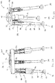
machine tool 101 in walking across a relativelyflat surface 138 is described in the following paragraphs with reference toFigs. 10A to 10G . - In
Fig. 10A , thecontroller 108 controls thesecond actuators 56 of the second andthird legs third actuators 58 of the second andthird legs third legs machine tool 101 is being supported by the fourth, fifth andsixth legs - In
Fig. 10B , thecontroller 108 controls thesecond actuators 56 of the second andthird legs third legs controller 108 may additionally control electromagnets or an air pump to secure the feet 50 of the second andthird legs surface 138. - In
Fig. 10C , thecontroller 108 controls thesecond actuators 56 of the fourth, fifth andsixth legs sixth legs controller 108 then controls thethird actuators 58 of the first, second andthird legs machine tool 101 forwards. At this stage, themachine tool 101 is being supported by the first, second andthird legs - At
Fig. 10D , thecontroller 108 controls thesecond actuators 56 of the fourth, fifth andsixth legs sixth legs controller 108 may additionally control electromagnets or an air pump to secure the feet 50 of the fourth, fifth andsixth legs surface 138. - At
Fig. 10E , thecontroller 108 controls thesecond actuators 56 of the first, second andthird legs third legs controller 108 controls thethird actuators 58 of the first, second andthird legs third legs machine tool 101 is being supported by the fourth, fifth andsixth legs - At
Fig. 10F , thecontroller 108 controls thesecond actuators 56 of the first, second andthird legs third legs controller 108 may additionally control electromagnets or an air pump to secure the feet 50 of the first, second andthird legs surface 138. - At
Fig. 10G , thecontroller 108 controls thefirst actuator 34 to rotate thefirst body 12 relative to the second body 14 (through ninety degrees as illustrated inFig. 10G ) to change the direction of walking of themachine tool 101 while the first, second andthird legs - The operation of the
machine tool 101 in walking across asurface 138 and up astep 140 is described in the following paragraphs with reference toFigs. 11A to 11F . - At
Fig. 11A , thecontroller 108 controls thesecond actuators 56 of the first, second andthird legs third legs controller 108 controls thethird actuators 58 of the first, second andthird legs third legs machine tool 101 is being supported by the fourth, fifth andsixth legs - At
Fig. 11B , thecontroller 108 controls thesecond actuators 56 of the first, second andthird legs third legs controller 108 may additionally control electromagnets or an air pump to secure the feet 50 of the first, second andthird legs surface 138. - At
Fig. 11C , thecontroller 108 controls thesecond actuators 56 of the fourth, fifth andsixth legs controller 108 controls thethird actuators 58 of the first, second andthird legs machine tool 101 forwards. - At
Fig. 11D , thecontroller 108 controls thesecond actuators 56 of the fourth, fifth andsixth legs fifth legs step 140 and until the foot 50 of thesixth leg 30 contacts thesurface 138 beneath the step 140 (block 128). - At
Fig. 11E , thecontroller 108 controls thesecond actuators 56 of the first, second andthird legs third legs controller 108 controls thethird actuators 58 of the first, second andthird legs third legs - At
Fig. 11F , thecontroller 108 controls thesecond actuators 56 of the first, second andthird legs first leg 18 contacts thestep 140 and until the feet 50 of the second andthird legs surface 138 beneath the step 140 (block 128). - The
controller 108 may then repeat the blocks illustrated inFigs. 11C to 11F to continue to walk up thestep 140 and across thesurface 138. - The operation of a
further machine tool 140 in changing machining stiffness is described in the following paragraphs with reference toFigs. 12A to 12D . Themachine tool 140 has substantially the same structure as themachine tool 101 and differs only in that thefirst body 12 and thesecond body 14 have a three armed star shape (where a leg is positioned at the end of each arm) instead of having a triangular shape. - At
Fig. 12A , thefirst body 12, thesecond body 14 and the first tosixth legs first leg 18 and thefourth leg 26, between thefourth leg 26 and thesecond leg 20, between thesecond leg 20 and thefifth leg 28, between thefifth leg 28 and thethird leg 22, between thethird leg 22 and thesixth leg 30, and between thesixth leg 30 and thefirst leg 18. - At
Fig. 12B , thecontroller 108 controls thesecond actuators 56 of the first, second andthird legs controller 108 then controls thefirst actuator 34 to rotate thefirst body 12 clockwise relative to the second body 14 (block 132) to reduce the angle defined between thefirst leg 18 and thefourth leg 26, between thefourth leg 26 and thesecond leg 20, between thesecond leg 20 and thefifth leg 28, between thefifth leg 28 and thethird leg 22, between thethird leg 22 and thesixth leg 30, and between thesixth leg 30 and thefirst leg 18. - At
Fig. 12C , thecontroller 108 controls thesecond actuators 56 of the first, second andthird legs third legs - At
Fig. 12D , thecontroller 108 controls thefirst actuator 34 to rotate thefirst body 12 anti-clockwise and thesecond body 14 clockwise to advantageously select the work volume and stiffness of the machine tool 101 (where the stiffness of themachine tool 101 is greater where thelegs controller 108 may then control thethird actuators 58 of the first, second, third, fourth, fifth andsixth legs cables second joints controller 108 may then control thesecond actuators 56 of the first, second, third, fourth, fifth andsixth legs - The
machine tool machine tool machine tool machine tool machine tool legs legs machine tool first body 12 and thesecond body 14. - It will be understood that the invention is not limited to the embodiments above-described and various modifications and improvements can be made without departing from the concepts described herein.
- For example, one or more of the
third actuators 58 may have the alternative structure illustrated inFig. 13 . Thethird actuator 58 illustrated inFig. 13 comprises aresilient member 142 instead of thesecond servomotor 62, thesecond screw 66, thesecond cable anchor 69 and the second pair ofcables 71. In the illustrated example, theresilient member 142 comprises a pair of parallel springs that extend between thefirst body 12 and asupport member 144 connected to the first leg 18 (for example). Theresilient member 142 is selected to provide sufficient force to drive thefirst leg 18 forwards and backwards in cooperation with thefirst servomotor 60. Thethird actuator 58 illustrated inFig. 13 may be advantageous in that it may reduce the number of motors of a machine tool and may consequently reduce the weight and complexity of the machine tool. - Except where mutually exclusive, any of the features may be employed separately or in combination with any other features and the disclosure extends to and includes all combinations and sub-combinations of one or more features described herein.
Claims (15)
- A machine tool comprising:a first body;a first leg, a second leg, and a third leg coupled to the first body via first joints and configured to support at least the first body;a second body including a tool holder;a fourth leg, a fifth leg, and a sixth leg coupled to the second body via second joints and configured to support at least the second body; anda first actuator coupled to the first body and to the second body, the first actuator being configured to cause rotational motion between the first body and the second body to enable a change in walking direction of the machine tool and/or to enable a change in machining stiffness and a change in work volume of the machine tool.
- A machine tool as claimed in claim 1, wherein the first body has a first axis and the second body has a second axis, the first axis and the second axis being offset relative to one another so that the first body and the second body are eccentric.
- A machine tool as claimed in claim 1, wherein the first body has a first axis and the second body has a second axis, the first axis and the second axis defining a common centre of the first body and the second body so that the first body and the second body are concentric.
- A machine tool as claimed in any of the preceding claims, wherein the first actuator is configured to cause rotational motion between the first body and the second body while the first leg, the second leg, the third leg, the fourth leg, the fifth leg and the sixth leg contact a surface to change the machining stiffness of the machine tool.
- A machine tool as claimed in any of the preceding claims, wherein the first leg, the second leg, the third leg, the fourth leg, the fifth leg, and the sixth leg each comprise: a second actuator and a prismatic joint, the second actuators being configured to move the respective legs between an extended state and a retracted state at their respective prismatic joints.
- A machine tool as claimed in claim 5, wherein the fourth leg, the fifth leg, and the sixth leg are configured to support the machine tool while in the extended state and while the first leg, the second leg and the third leg are in the retracted state, to enable the first actuator to cause rotational motion between the first body and the second body to enable a change in walking direction of the machine tool.
- A machine tool as claimed in any of the preceding claims, wherein the first leg, the second leg and the third leg each comprise a third actuator, the third actuators being configured to pivot the respective first, second and third legs about their respective first joints to enable the machine tool to walk.
- A machine tool as claimed in any of the preceding claims, wherein the second leg and the third leg are configured to rotate relative to the first body, the machine tool comprising a fourth actuator to rotate the second and third legs to change the state of the machine tool between a walking state and a machining state.
- A machine tool as claimed in any of the preceding claims, wherein the second body includes a first cylindrical protrusion and the first actuator comprises a gear positioned adjacent to the first cylindrical protrusion, the first body defining a cavity therein for receiving the first cylindrical protrusion and the gear, the first body including a plurality of teeth within the cavity for engaging the gear of the first actuator.
- A machine tool as claimed in claim 9, wherein the second body includes a second cylindrical protrusion positioned within the first cylindrical protrusion, the second cylindrical protrusion being eccentric with the second axis of the second body and with the first cylindrical protrusion, the second cylindrical protrusion being coupled to the tool holder, the tool holder being eccentric with the second cylindrical protrusion.
- A method of controlling a machine tool as claimed in any of claims 1 to 4, the method comprising:receiving a signal from a user input device and/or from a sensor; andcontrolling the first actuator, using the received signal, to cause rotational motion between the first body and the second body.
- A method as claimed in claim 11, wherein the first leg, the second leg, the third leg, the fourth leg, the fifth leg, and the sixth leg each comprise: a second actuator and a prismatic joint, the method further comprising controlling the second actuators of the first, second, and third legs or the second actuators of the fourth, fifth, and sixth legs, to move the respective legs between an extended state and a retracted state at their respective prismatic joints.
- A method as claimed in claim 11 or 12, wherein the first leg, the second leg and the third leg each comprise a third actuator, the method further comprising controlling the third actuators to pivot the respective first, second and third legs about their respective first joints to enable the machine tool to walk.
- A method as claimed in any of claims 11 to 13, wherein the second leg and the third leg are configured to rotate relative to the first body and the machine tool further comprises a fourth actuator for rotating the second and third legs relative to the first body, wherein the method further comprises controlling the fourth actuator to rotate the second and third legs to change the state of the machine tool between a walking state and a machining state.
- Apparatus to control a machine tool, the apparatus comprising:a controller to perform the method as claimed in any of claims 11 to 14.
Applications Claiming Priority (1)
| Application Number | Priority Date | Filing Date | Title |
|---|---|---|---|
| GBGB1504846.5A GB201504846D0 (en) | 2015-03-23 | 2015-03-23 | Machine tools |
Publications (2)
| Publication Number | Publication Date |
|---|---|
| EP3072789A1 true EP3072789A1 (en) | 2016-09-28 |
| EP3072789B1 EP3072789B1 (en) | 2017-12-13 |
Family
ID=53052215
Family Applications (1)
| Application Number | Title | Priority Date | Filing Date |
|---|---|---|---|
| EP16160582.9A Active EP3072789B1 (en) | 2015-03-23 | 2016-03-16 | Machine tool with walking apparatus |
Country Status (3)
| Country | Link |
|---|---|
| US (1) | US10040151B2 (en) |
| EP (1) | EP3072789B1 (en) |
| GB (1) | GB201504846D0 (en) |
Cited By (2)
| Publication number | Priority date | Publication date | Assignee | Title |
|---|---|---|---|---|
| CN109241610A (en) * | 2018-08-31 | 2019-01-18 | 东南大学 | Consider the high-speed processing machine tool complete machine structure dynamic design approach of engaging portion rigidity |
| FR3070887A1 (en) * | 2017-09-11 | 2019-03-15 | Psa Automobiles Sa | SUPPORT FOR ELECTRIC SCREWDRIVER |
Families Citing this family (6)
| Publication number | Priority date | Publication date | Assignee | Title |
|---|---|---|---|---|
| US11458579B2 (en) | 2013-12-06 | 2022-10-04 | Huber Diffraktionstechnik Gmbh & Co. Kg | Redundant parallel positioning table device |
| US10955084B2 (en) * | 2013-12-06 | 2021-03-23 | Huber Diffraktionstechnik Gmbh & Co. Kg | Redundant parallel positioning table device |
| JP2018004005A (en) * | 2016-07-06 | 2018-01-11 | ソニー株式会社 | Expansion mechanism and tetrapodal robot |
| CN112417736B (en) * | 2020-12-03 | 2022-08-16 | 天津大学 | Method for designing static stiffness of complete machine tool |
| CN112936225B (en) * | 2021-01-28 | 2023-06-27 | 燕山大学 | Few-drive multi-degree-of-freedom output redundancy parallel mechanism and control method |
| CN114379669B (en) * | 2021-12-31 | 2022-12-27 | 德清县浙工大莫干山研究院 | Reconfigurable four-footed mobile platform |
Citations (4)
| Publication number | Priority date | Publication date | Assignee | Title |
|---|---|---|---|---|
| JPS60104474A (en) * | 1983-11-09 | 1985-06-08 | Nippon Kokan Kk <Nkk> | Walking device |
| WO2010043284A2 (en) * | 2008-10-13 | 2010-04-22 | Rolls-Royce Plc | Machine tool |
| US20100107795A1 (en) * | 2008-11-03 | 2010-05-06 | Viola Robert J | Frame walker predicated on a parallel mechanism |
| EP2781312A2 (en) * | 2013-03-18 | 2014-09-24 | Rolls-Royce plc | Machine tool |
Family Cites Families (7)
| Publication number | Priority date | Publication date | Assignee | Title |
|---|---|---|---|---|
| GB8408458D0 (en) * | 1984-04-02 | 1984-05-10 | Stewart D E S | Vehicle |
| US5468099A (en) | 1993-08-11 | 1995-11-21 | Vought Aircraft Company | Seam tracking drilling machine |
| US5656905A (en) * | 1995-04-03 | 1997-08-12 | Tsai; Lung-Wen | Multi-degree-of-freedom mechanisms for machine tools and the like |
| US7339340B2 (en) * | 2005-03-23 | 2008-03-04 | Harris Corporation | Control system and related method for multi-limbed, multi-legged robot |
| WO2006107664A2 (en) | 2005-04-01 | 2006-10-12 | Trustees Of Stevens Institute Of Technology | Flexible parallel manipulator for nano-, meso-or macro-positioning with multi-degrees of freedom |
| US20060235551A1 (en) * | 2005-04-13 | 2006-10-19 | Creative Technology Ltd. | Data storage device with audio capability |
| DE102006011823A1 (en) * | 2006-03-13 | 2007-09-20 | Abb Patent Gmbh | positioning |
-
2015
- 2015-03-23 GB GBGB1504846.5A patent/GB201504846D0/en not_active Ceased
-
2016
- 2016-03-16 EP EP16160582.9A patent/EP3072789B1/en active Active
- 2016-03-17 US US15/073,054 patent/US10040151B2/en active Active
Patent Citations (4)
| Publication number | Priority date | Publication date | Assignee | Title |
|---|---|---|---|---|
| JPS60104474A (en) * | 1983-11-09 | 1985-06-08 | Nippon Kokan Kk <Nkk> | Walking device |
| WO2010043284A2 (en) * | 2008-10-13 | 2010-04-22 | Rolls-Royce Plc | Machine tool |
| US20100107795A1 (en) * | 2008-11-03 | 2010-05-06 | Viola Robert J | Frame walker predicated on a parallel mechanism |
| EP2781312A2 (en) * | 2013-03-18 | 2014-09-24 | Rolls-Royce plc | Machine tool |
Cited By (3)
| Publication number | Priority date | Publication date | Assignee | Title |
|---|---|---|---|---|
| FR3070887A1 (en) * | 2017-09-11 | 2019-03-15 | Psa Automobiles Sa | SUPPORT FOR ELECTRIC SCREWDRIVER |
| CN109241610A (en) * | 2018-08-31 | 2019-01-18 | 东南大学 | Consider the high-speed processing machine tool complete machine structure dynamic design approach of engaging portion rigidity |
| CN109241610B (en) * | 2018-08-31 | 2019-10-11 | 东南大学 | Consider the high-speed processing machine tool complete machine structure dynamic design approach of engaging portion rigidity |
Also Published As
| Publication number | Publication date |
|---|---|
| GB201504846D0 (en) | 2015-05-06 |
| US10040151B2 (en) | 2018-08-07 |
| EP3072789B1 (en) | 2017-12-13 |
| US20160279750A1 (en) | 2016-09-29 |
Similar Documents
| Publication | Publication Date | Title |
|---|---|---|
| EP3072789B1 (en) | Machine tool with walking apparatus | |
| EP3095564B1 (en) | Robot for inspection of confined spaces | |
| CN107820456B (en) | Method for redundantly optimally planning the operation of a mobile robot | |
| CN111819510B (en) | flying robot | |
| ES2700282T3 (en) | Robotics-based monument system for metrology systems | |
| KR20220012921A (en) | Robot configuration with 3D lidar | |
| US11298826B1 (en) | Modular robot system | |
| EP3020519A1 (en) | Robot, and joint mechanism for robot | |
| JP6472854B1 (en) | Work equipment | |
| US20190129374A1 (en) | Control Device, Robot, And Robot System | |
| JP6892018B2 (en) | Robot device | |
| CN104633407A (en) | Three-degree-of-freedom rotating platform | |
| CN114080301A (en) | Independently translating coaxial robotic arm and sensing housing | |
| CN203726501U (en) | Foldable light type mechanical arm capable of following and monitoring target | |
| JP2010284728A (en) | Conveyance robot and automatic teaching method | |
| WO2018081725A1 (en) | Movable base for a robotic system | |
| CN103802132A (en) | Folding lightweight mechanical arm with target following and monitoring function | |
| US20150217454A1 (en) | Calibration Tool For A Delta Robot | |
| CN104044138A (en) | 8-UPS (Uninterruptible Power Supply) walking processing parallel robot | |
| US10081102B1 (en) | Antagonistic output actuation | |
| CN113043332B (en) | Arm shape measuring system and method of rope-driven flexible robot | |
| GB2557179A (en) | Methods, apparatus, computer programs and non-transitory computer readable storage mediums for controlling a hyper redundant manipulator | |
| JP5582432B1 (en) | Helical scanning mechanism and three-dimensional positioning device | |
| Aboulissane et al. | 3-UPU robotic mechanism performance evaluation through kinematic indexes | |
| KR101221016B1 (en) | Exploration Robot |
Legal Events
| Date | Code | Title | Description |
|---|---|---|---|
| PUAI | Public reference made under article 153(3) epc to a published international application that has entered the european phase |
Free format text: ORIGINAL CODE: 0009012 |
|
| AK | Designated contracting states |
Kind code of ref document: A1 Designated state(s): AL AT BE BG CH CY CZ DE DK EE ES FI FR GB GR HR HU IE IS IT LI LT LU LV MC MK MT NL NO PL PT RO RS SE SI SK SM TR |
|
| AX | Request for extension of the european patent |
Extension state: BA ME |
|
| 17P | Request for examination filed |
Effective date: 20170324 |
|
| RBV | Designated contracting states (corrected) |
Designated state(s): AL AT BE BG CH CY CZ DE DK EE ES FI FR GB GR HR HU IE IS IT LI LT LU LV MC MK MT NL NO PL PT RO RS SE SI SK SM TR |
|
| GRAP | Despatch of communication of intention to grant a patent |
Free format text: ORIGINAL CODE: EPIDOSNIGR1 |
|
| GRAS | Grant fee paid |
Free format text: ORIGINAL CODE: EPIDOSNIGR3 |
|
| GRAA | (expected) grant |
Free format text: ORIGINAL CODE: 0009210 |
|
| INTG | Intention to grant announced |
Effective date: 20171018 |
|
| REG | Reference to a national code |
Ref country code: GB Ref legal event code: FG4D |
|
| REG | Reference to a national code |
Ref country code: AT Ref legal event code: REF Ref document number: 954082 Country of ref document: AT Kind code of ref document: T Effective date: 20171215 Ref country code: CH Ref legal event code: EP |
|
| REG | Reference to a national code |
Ref country code: IE Ref legal event code: FG4D |
|
| REG | Reference to a national code |
Ref country code: DE Ref legal event code: R096 Ref document number: 602016001046 Country of ref document: DE |
|
| REG | Reference to a national code |
Ref country code: FR Ref legal event code: PLFP Year of fee payment: 3 |
|
| REG | Reference to a national code |
Ref country code: NL Ref legal event code: MP Effective date: 20171213 |
|
| PG25 | Lapsed in a contracting state [announced via postgrant information from national office to epo] |
Ref country code: FI Free format text: LAPSE BECAUSE OF FAILURE TO SUBMIT A TRANSLATION OF THE DESCRIPTION OR TO PAY THE FEE WITHIN THE PRESCRIBED TIME-LIMIT Effective date: 20171213 Ref country code: NO Free format text: LAPSE BECAUSE OF FAILURE TO SUBMIT A TRANSLATION OF THE DESCRIPTION OR TO PAY THE FEE WITHIN THE PRESCRIBED TIME-LIMIT Effective date: 20180313 Ref country code: SE Free format text: LAPSE BECAUSE OF FAILURE TO SUBMIT A TRANSLATION OF THE DESCRIPTION OR TO PAY THE FEE WITHIN THE PRESCRIBED TIME-LIMIT Effective date: 20171213 |
|
| REG | Reference to a national code |
Ref country code: AT Ref legal event code: MK05 Ref document number: 954082 Country of ref document: AT Kind code of ref document: T Effective date: 20171213 |
|
| PG25 | Lapsed in a contracting state [announced via postgrant information from national office to epo] |
Ref country code: LV Free format text: LAPSE BECAUSE OF FAILURE TO SUBMIT A TRANSLATION OF THE DESCRIPTION OR TO PAY THE FEE WITHIN THE PRESCRIBED TIME-LIMIT Effective date: 20171213 Ref country code: GR Free format text: LAPSE BECAUSE OF FAILURE TO SUBMIT A TRANSLATION OF THE DESCRIPTION OR TO PAY THE FEE WITHIN THE PRESCRIBED TIME-LIMIT Effective date: 20180314 Ref country code: HR Free format text: LAPSE BECAUSE OF FAILURE TO SUBMIT A TRANSLATION OF THE DESCRIPTION OR TO PAY THE FEE WITHIN THE PRESCRIBED TIME-LIMIT Effective date: 20171213 Ref country code: BG Free format text: LAPSE BECAUSE OF FAILURE TO SUBMIT A TRANSLATION OF THE DESCRIPTION OR TO PAY THE FEE WITHIN THE PRESCRIBED TIME-LIMIT Effective date: 20180313 Ref country code: RS Free format text: LAPSE BECAUSE OF FAILURE TO SUBMIT A TRANSLATION OF THE DESCRIPTION OR TO PAY THE FEE WITHIN THE PRESCRIBED TIME-LIMIT Effective date: 20171213 |
|
| PG25 | Lapsed in a contracting state [announced via postgrant information from national office to epo] |
Ref country code: NL Free format text: LAPSE BECAUSE OF FAILURE TO SUBMIT A TRANSLATION OF THE DESCRIPTION OR TO PAY THE FEE WITHIN THE PRESCRIBED TIME-LIMIT Effective date: 20171213 |
|
| PG25 | Lapsed in a contracting state [announced via postgrant information from national office to epo] |
Ref country code: ES Free format text: LAPSE BECAUSE OF FAILURE TO SUBMIT A TRANSLATION OF THE DESCRIPTION OR TO PAY THE FEE WITHIN THE PRESCRIBED TIME-LIMIT Effective date: 20171213 Ref country code: SK Free format text: LAPSE BECAUSE OF FAILURE TO SUBMIT A TRANSLATION OF THE DESCRIPTION OR TO PAY THE FEE WITHIN THE PRESCRIBED TIME-LIMIT Effective date: 20171213 Ref country code: EE Free format text: LAPSE BECAUSE OF FAILURE TO SUBMIT A TRANSLATION OF THE DESCRIPTION OR TO PAY THE FEE WITHIN THE PRESCRIBED TIME-LIMIT Effective date: 20171213 Ref country code: CZ Free format text: LAPSE BECAUSE OF FAILURE TO SUBMIT A TRANSLATION OF THE DESCRIPTION OR TO PAY THE FEE WITHIN THE PRESCRIBED TIME-LIMIT Effective date: 20171213 Ref country code: CY Free format text: LAPSE BECAUSE OF FAILURE TO SUBMIT A TRANSLATION OF THE DESCRIPTION OR TO PAY THE FEE WITHIN THE PRESCRIBED TIME-LIMIT Effective date: 20171213 |
|
| PG25 | Lapsed in a contracting state [announced via postgrant information from national office to epo] |
Ref country code: IT Free format text: LAPSE BECAUSE OF FAILURE TO SUBMIT A TRANSLATION OF THE DESCRIPTION OR TO PAY THE FEE WITHIN THE PRESCRIBED TIME-LIMIT Effective date: 20171213 Ref country code: PL Free format text: LAPSE BECAUSE OF FAILURE TO SUBMIT A TRANSLATION OF THE DESCRIPTION OR TO PAY THE FEE WITHIN THE PRESCRIBED TIME-LIMIT Effective date: 20171213 Ref country code: SM Free format text: LAPSE BECAUSE OF FAILURE TO SUBMIT A TRANSLATION OF THE DESCRIPTION OR TO PAY THE FEE WITHIN THE PRESCRIBED TIME-LIMIT Effective date: 20171213 Ref country code: IS Free format text: LAPSE BECAUSE OF FAILURE TO SUBMIT A TRANSLATION OF THE DESCRIPTION OR TO PAY THE FEE WITHIN THE PRESCRIBED TIME-LIMIT Effective date: 20180413 Ref country code: AT Free format text: LAPSE BECAUSE OF FAILURE TO SUBMIT A TRANSLATION OF THE DESCRIPTION OR TO PAY THE FEE WITHIN THE PRESCRIBED TIME-LIMIT Effective date: 20171213 Ref country code: RO Free format text: LAPSE BECAUSE OF FAILURE TO SUBMIT A TRANSLATION OF THE DESCRIPTION OR TO PAY THE FEE WITHIN THE PRESCRIBED TIME-LIMIT Effective date: 20171213 |
|
| REG | Reference to a national code |
Ref country code: DE Ref legal event code: R097 Ref document number: 602016001046 Country of ref document: DE |
|
| PLBE | No opposition filed within time limit |
Free format text: ORIGINAL CODE: 0009261 |
|
| STAA | Information on the status of an ep patent application or granted ep patent |
Free format text: STATUS: NO OPPOSITION FILED WITHIN TIME LIMIT |
|
| 26N | No opposition filed |
Effective date: 20180914 |
|
| PG25 | Lapsed in a contracting state [announced via postgrant information from national office to epo] |
Ref country code: DK Free format text: LAPSE BECAUSE OF FAILURE TO SUBMIT A TRANSLATION OF THE DESCRIPTION OR TO PAY THE FEE WITHIN THE PRESCRIBED TIME-LIMIT Effective date: 20171213 Ref country code: MC Free format text: LAPSE BECAUSE OF FAILURE TO SUBMIT A TRANSLATION OF THE DESCRIPTION OR TO PAY THE FEE WITHIN THE PRESCRIBED TIME-LIMIT Effective date: 20171213 |
|
| REG | Reference to a national code |
Ref country code: BE Ref legal event code: MM Effective date: 20180331 |
|
| REG | Reference to a national code |
Ref country code: IE Ref legal event code: MM4A |
|
| PG25 | Lapsed in a contracting state [announced via postgrant information from national office to epo] |
Ref country code: LU Free format text: LAPSE BECAUSE OF NON-PAYMENT OF DUE FEES Effective date: 20180316 |
|
| PG25 | Lapsed in a contracting state [announced via postgrant information from national office to epo] |
Ref country code: IE Free format text: LAPSE BECAUSE OF NON-PAYMENT OF DUE FEES Effective date: 20180316 |
|
| PG25 | Lapsed in a contracting state [announced via postgrant information from national office to epo] |
Ref country code: BE Free format text: LAPSE BECAUSE OF NON-PAYMENT OF DUE FEES Effective date: 20180331 Ref country code: SI Free format text: LAPSE BECAUSE OF FAILURE TO SUBMIT A TRANSLATION OF THE DESCRIPTION OR TO PAY THE FEE WITHIN THE PRESCRIBED TIME-LIMIT Effective date: 20171213 |
|
| REG | Reference to a national code |
Ref country code: CH Ref legal event code: PL |
|
| PG25 | Lapsed in a contracting state [announced via postgrant information from national office to epo] |
Ref country code: LI Free format text: LAPSE BECAUSE OF NON-PAYMENT OF DUE FEES Effective date: 20190331 Ref country code: CH Free format text: LAPSE BECAUSE OF NON-PAYMENT OF DUE FEES Effective date: 20190331 Ref country code: MT Free format text: LAPSE BECAUSE OF NON-PAYMENT OF DUE FEES Effective date: 20180316 |
|
| PG25 | Lapsed in a contracting state [announced via postgrant information from national office to epo] |
Ref country code: TR Free format text: LAPSE BECAUSE OF FAILURE TO SUBMIT A TRANSLATION OF THE DESCRIPTION OR TO PAY THE FEE WITHIN THE PRESCRIBED TIME-LIMIT Effective date: 20171213 |
|
| PG25 | Lapsed in a contracting state [announced via postgrant information from national office to epo] |
Ref country code: PT Free format text: LAPSE BECAUSE OF FAILURE TO SUBMIT A TRANSLATION OF THE DESCRIPTION OR TO PAY THE FEE WITHIN THE PRESCRIBED TIME-LIMIT Effective date: 20171213 |
|
| PG25 | Lapsed in a contracting state [announced via postgrant information from national office to epo] |
Ref country code: LT Free format text: LAPSE BECAUSE OF FAILURE TO SUBMIT A TRANSLATION OF THE DESCRIPTION OR TO PAY THE FEE WITHIN THE PRESCRIBED TIME-LIMIT Effective date: 20171213 Ref country code: HU Free format text: LAPSE BECAUSE OF FAILURE TO SUBMIT A TRANSLATION OF THE DESCRIPTION OR TO PAY THE FEE WITHIN THE PRESCRIBED TIME-LIMIT; INVALID AB INITIO Effective date: 20160316 Ref country code: MK Free format text: LAPSE BECAUSE OF NON-PAYMENT OF DUE FEES Effective date: 20171213 |
|
| PG25 | Lapsed in a contracting state [announced via postgrant information from national office to epo] |
Ref country code: AL Free format text: LAPSE BECAUSE OF FAILURE TO SUBMIT A TRANSLATION OF THE DESCRIPTION OR TO PAY THE FEE WITHIN THE PRESCRIBED TIME-LIMIT Effective date: 20171213 |
|
| PGFP | Annual fee paid to national office [announced via postgrant information from national office to epo] |
Ref country code: FR Payment date: 20230323 Year of fee payment: 8 |
|
| PGFP | Annual fee paid to national office [announced via postgrant information from national office to epo] |
Ref country code: GB Payment date: 20230321 Year of fee payment: 8 Ref country code: DE Payment date: 20230328 Year of fee payment: 8 |
|
| P01 | Opt-out of the competence of the unified patent court (upc) registered |
Effective date: 20230528 |