EP3072763A1 - Brake disc stack wear measurement - Google Patents
Brake disc stack wear measurement Download PDFInfo
- Publication number
- EP3072763A1 EP3072763A1 EP16159532.7A EP16159532A EP3072763A1 EP 3072763 A1 EP3072763 A1 EP 3072763A1 EP 16159532 A EP16159532 A EP 16159532A EP 3072763 A1 EP3072763 A1 EP 3072763A1
- Authority
- EP
- European Patent Office
- Prior art keywords
- sensor
- emitter
- wear
- brake disc
- disc stack
- Prior art date
- Legal status (The legal status is an assumption and is not a legal conclusion. Google has not performed a legal analysis and makes no representation as to the accuracy of the status listed.)
- Granted
Links
Images



Classifications
-
- B—PERFORMING OPERATIONS; TRANSPORTING
- B60—VEHICLES IN GENERAL
- B60T—VEHICLE BRAKE CONTROL SYSTEMS OR PARTS THEREOF; BRAKE CONTROL SYSTEMS OR PARTS THEREOF, IN GENERAL; ARRANGEMENT OF BRAKING ELEMENTS ON VEHICLES IN GENERAL; PORTABLE DEVICES FOR PREVENTING UNWANTED MOVEMENT OF VEHICLES; VEHICLE MODIFICATIONS TO FACILITATE COOLING OF BRAKES
- B60T17/00—Component parts, details, or accessories of power brake systems not covered by groups B60T8/00, B60T13/00 or B60T15/00, or presenting other characteristic features
- B60T17/18—Safety devices; Monitoring
- B60T17/22—Devices for monitoring or checking brake systems; Signal devices
-
- G—PHYSICS
- G01—MEASURING; TESTING
- G01B—MEASURING LENGTH, THICKNESS OR SIMILAR LINEAR DIMENSIONS; MEASURING ANGLES; MEASURING AREAS; MEASURING IRREGULARITIES OF SURFACES OR CONTOURS
- G01B7/00—Measuring arrangements characterised by the use of electric or magnetic techniques
- G01B7/02—Measuring arrangements characterised by the use of electric or magnetic techniques for measuring length, width or thickness
-
- F—MECHANICAL ENGINEERING; LIGHTING; HEATING; WEAPONS; BLASTING
- F16—ENGINEERING ELEMENTS AND UNITS; GENERAL MEASURES FOR PRODUCING AND MAINTAINING EFFECTIVE FUNCTIONING OF MACHINES OR INSTALLATIONS; THERMAL INSULATION IN GENERAL
- F16D—COUPLINGS FOR TRANSMITTING ROTATION; CLUTCHES; BRAKES
- F16D66/00—Arrangements for monitoring working conditions, e.g. wear, temperature
- F16D66/02—Apparatus for indicating wear
- F16D66/021—Apparatus for indicating wear using electrical detection or indication means
- F16D66/022—Apparatus for indicating wear using electrical detection or indication means indicating that a lining is worn to minimum allowable thickness
- F16D66/023—Apparatus for indicating wear using electrical detection or indication means indicating that a lining is worn to minimum allowable thickness directly sensing the position of braking members
- F16D66/024—Sensors mounted on braking members adapted to contact the brake disc or drum, e.g. wire loops severed on contact
-
- F—MECHANICAL ENGINEERING; LIGHTING; HEATING; WEAPONS; BLASTING
- F16—ENGINEERING ELEMENTS AND UNITS; GENERAL MEASURES FOR PRODUCING AND MAINTAINING EFFECTIVE FUNCTIONING OF MACHINES OR INSTALLATIONS; THERMAL INSULATION IN GENERAL
- F16D—COUPLINGS FOR TRANSMITTING ROTATION; CLUTCHES; BRAKES
- F16D55/00—Brakes with substantially-radial braking surfaces pressed together in axial direction, e.g. disc brakes
- F16D55/24—Brakes with substantially-radial braking surfaces pressed together in axial direction, e.g. disc brakes with a plurality of axially-movable discs, lamellae, or pads, pressed from one side towards an axially-located member
- F16D55/26—Brakes with substantially-radial braking surfaces pressed together in axial direction, e.g. disc brakes with a plurality of axially-movable discs, lamellae, or pads, pressed from one side towards an axially-located member without self-tightening action
- F16D55/36—Brakes with a plurality of rotating discs all lying side by side
- F16D55/38—Brakes with a plurality of rotating discs all lying side by side mechanically actuated
-
- F—MECHANICAL ENGINEERING; LIGHTING; HEATING; WEAPONS; BLASTING
- F16—ENGINEERING ELEMENTS AND UNITS; GENERAL MEASURES FOR PRODUCING AND MAINTAINING EFFECTIVE FUNCTIONING OF MACHINES OR INSTALLATIONS; THERMAL INSULATION IN GENERAL
- F16D—COUPLINGS FOR TRANSMITTING ROTATION; CLUTCHES; BRAKES
- F16D55/00—Brakes with substantially-radial braking surfaces pressed together in axial direction, e.g. disc brakes
- F16D55/24—Brakes with substantially-radial braking surfaces pressed together in axial direction, e.g. disc brakes with a plurality of axially-movable discs, lamellae, or pads, pressed from one side towards an axially-located member
- F16D55/26—Brakes with substantially-radial braking surfaces pressed together in axial direction, e.g. disc brakes with a plurality of axially-movable discs, lamellae, or pads, pressed from one side towards an axially-located member without self-tightening action
- F16D55/36—Brakes with a plurality of rotating discs all lying side by side
- F16D55/40—Brakes with a plurality of rotating discs all lying side by side actuated by a fluid-pressure device arranged in or one the brake
-
- F—MECHANICAL ENGINEERING; LIGHTING; HEATING; WEAPONS; BLASTING
- F16—ENGINEERING ELEMENTS AND UNITS; GENERAL MEASURES FOR PRODUCING AND MAINTAINING EFFECTIVE FUNCTIONING OF MACHINES OR INSTALLATIONS; THERMAL INSULATION IN GENERAL
- F16D—COUPLINGS FOR TRANSMITTING ROTATION; CLUTCHES; BRAKES
- F16D65/00—Parts or details
- F16D65/38—Slack adjusters
- F16D65/40—Slack adjusters mechanical
- F16D65/52—Slack adjusters mechanical self-acting in one direction for adjusting excessive play
-
- F—MECHANICAL ENGINEERING; LIGHTING; HEATING; WEAPONS; BLASTING
- F16—ENGINEERING ELEMENTS AND UNITS; GENERAL MEASURES FOR PRODUCING AND MAINTAINING EFFECTIVE FUNCTIONING OF MACHINES OR INSTALLATIONS; THERMAL INSULATION IN GENERAL
- F16D—COUPLINGS FOR TRANSMITTING ROTATION; CLUTCHES; BRAKES
- F16D66/00—Arrangements for monitoring working conditions, e.g. wear, temperature
- F16D66/02—Apparatus for indicating wear
- F16D66/021—Apparatus for indicating wear using electrical detection or indication means
-
- F—MECHANICAL ENGINEERING; LIGHTING; HEATING; WEAPONS; BLASTING
- F16—ENGINEERING ELEMENTS AND UNITS; GENERAL MEASURES FOR PRODUCING AND MAINTAINING EFFECTIVE FUNCTIONING OF MACHINES OR INSTALLATIONS; THERMAL INSULATION IN GENERAL
- F16D—COUPLINGS FOR TRANSMITTING ROTATION; CLUTCHES; BRAKES
- F16D66/00—Arrangements for monitoring working conditions, e.g. wear, temperature
- F16D66/02—Apparatus for indicating wear
- F16D66/021—Apparatus for indicating wear using electrical detection or indication means
- F16D66/022—Apparatus for indicating wear using electrical detection or indication means indicating that a lining is worn to minimum allowable thickness
- F16D66/025—Apparatus for indicating wear using electrical detection or indication means indicating that a lining is worn to minimum allowable thickness sensing the position of parts of the brake system other than the braking members, e.g. limit switches mounted on primary cylinders
-
- G—PHYSICS
- G01—MEASURING; TESTING
- G01B—MEASURING LENGTH, THICKNESS OR SIMILAR LINEAR DIMENSIONS; MEASURING ANGLES; MEASURING AREAS; MEASURING IRREGULARITIES OF SURFACES OR CONTOURS
- G01B11/00—Measuring arrangements characterised by the use of optical techniques
- G01B11/02—Measuring arrangements characterised by the use of optical techniques for measuring length, width or thickness
-
- G—PHYSICS
- G01—MEASURING; TESTING
- G01B—MEASURING LENGTH, THICKNESS OR SIMILAR LINEAR DIMENSIONS; MEASURING ANGLES; MEASURING AREAS; MEASURING IRREGULARITIES OF SURFACES OR CONTOURS
- G01B17/00—Measuring arrangements characterised by the use of infrasonic, sonic or ultrasonic vibrations
-
- G—PHYSICS
- G01—MEASURING; TESTING
- G01N—INVESTIGATING OR ANALYSING MATERIALS BY DETERMINING THEIR CHEMICAL OR PHYSICAL PROPERTIES
- G01N27/00—Investigating or analysing materials by the use of electric, electrochemical, or magnetic means
- G01N27/72—Investigating or analysing materials by the use of electric, electrochemical, or magnetic means by investigating magnetic variables
Definitions
- This disclosure relates to vehicle braking systems, such as an aircraft braking assembly.
- a brake assembly of an aircraft or another vehicle has a limited useable life, as determined through wear, and may have an associated operating and maintenance cost that is based on the actual use of the brake assembly and how fast the life of the brake assembly is consumed. As a result of varying external factors and varying frictional forces during braking events, different brake assemblies may experience different rates of wear over time.
- a brake wear measurement system includes anemitter configured to emit a signal and a passive powered sensor system including a controller and a sensor configured to sense the signal emitted by the emitter.
- the emitter includes a magnetic field emitter and the sensor includes a magnetic field strength sensor.
- the emitter and the sensor of the sensor system are mounted on the brake assembly such as the emitter and the sensor may be configured to move relative to each other as the brake disc stack wears. Thus, a characteristic of the signal emitted by the emitter and sensed by the sensor may change as a function of the brake disc stack wear.
- the brake wear measurement may further include a processor configured to receive the output generated by the sensor and determine, based on the output, an amount of wear of the brake disc stack assembly.
- the amount of wear (or "level" of wear) can be, for example, a percentage of useful life of the brake disc stack remaining, a magnitude of wear (e.g., as measured in units of length), or any other suitable quantification of the amount of wear.
- the processor may reference a data structure that associates sensor outputs with the amount of brake disc stack wear in order to determine the amount of wear indicated by a particular sensor output.
- the disclosure is directed to a system comprising a brake disc stack and an emitter configured to emit a signal.
- the system further includes a sensor configured to sense the emitted signal, generate an output indicative of a characteristic of the sensed signal, wherein the sensor and the emitter are configured to move relative to each other as the brake disk stack wears.
- the system further includes a passively powered controller operatively coupled to the sensor and configured to wirelessly receive power from a remote device, receive the output generated by the sensor, and a processor configured to determine an amount of wear of the brake disc stack based on the output generated by the sensor.
- the controller may be configured to transmit, to the remote device, at least one of: information indicative of the output generated by the sensor or the amount of wear of the brake disc stack determined based on the output.
- the disclosure is directed to a method comprising emitting, by an emitter, a signal, and detecting, by a sensor, the signal emitted by the emitter.
- the method includes generating, by the sensor, an output indicative of a characteristic of the signal emitted by the emitter, and wirelessly receiving, by a passively powered controller, power from a remote device.
- the method further includes receiving, by the passively powered controller, the output generated by the sensor, and determining an amount of wear of a brake disc stack based on the output generated by the sensor.
- the disclosure is directed to a system comprising means means for emitting, by an emitter, a signal, and means for detecting, by a sensor, the signal emitted by the emitter.
- the system includes means for generating, by the sensor, an output indicative of a characteristic of the signal emitted by the emitter, and means for wirelessly receiving, by a passively powered controller, power from a remote device.
- the system further includes means for receiving, by the passively powered controller, the output generated by the sensor, and means for determining an amount of wear of a brake disc stack based on the output generated by the sensor.
- the disclosure is also directed to an article of manufacture comprising a computer-readable storage medium.
- the computer-readable storage medium comprises computer-readable instructions that are executable by a processor.
- the instructions cause the processor to perform any part of the techniques described herein.
- the instructions may be, for example, software instructions, such as those used to define a software or computer program.
- the computer-readable medium may be a computer-readable storage medium such as a storage device (e.g., a disk drive, or an optical drive), memory (e.g., a Flash memory, read only memory (ROM), or random access memory (RAM)) or any other type of volatile or non-volatile memory or storage element that stores instructions (e.g., in the form of a computer program or other executable) to cause a processor to perform the techniques described herein.
- the computer-readable medium may be a non-transitory storage medium.
- a brake wear measurement system includes anemitter and a passive powered sensor system including a controller and a sensor.
- the emitter and at least the sensorof the sensor system are mounted on the brake assembly such the emitter and sensor may be configured to move relative to each other as the brake disc stack wears.
- one of the emitter or the sensor may be mounted on a bracket and may remain stationary as the brake disc stack wears, and the other of the emitter or the sensor may be configured to move with the brake disc stack as it wears (e.g., on a wear pin or a pressure plate of the brake disc stack).
- the emitter and the sensor may not be electrically coupled to each other via wire.
- a characteristic of the signal emitted by the emitter and sensed by the sensor may change as a function of the brake disc stack wear.
- a processor may receive, from the sensor assembly,an indication of the characteristic of the signal sensed by the sensor and determine an amount of brake disc stack wear based on the characteristic of the signal sensed by the sensor.
- the emitter may include a magnet that emits a magnetic field
- different levels of brake disc stack wear may be associated with different magnetic field characteristics, e.g., in a mapping table or other data structure
- the processor may compare the received magnetic field characteristic to the data structure to determine the brake disc stack wear.
- the magnetic field characteristics may be associated with values corresponding to a distance between the field emitter and the sensor, which may change as a function of the amount of brake disc stack wear.
- the processor can be a part of the sensor assembly mounted on the aircraft brake assembly or can be part of a remote device, separate from and not wired to the sensor assembly.
- the emitter, the sensor system, or both the emitter and sensor system may be passively powered.
- the sensor system may be passively powered by the remote device.
- the remote device may emit energy (e.g., electromagnetic waves)that powers the sensor system, and, in response to being powered, the sensor system may transmit an indication of a characteristic of the signal sensed by the sensor or an amount of brake disc wear determined based on the characteristic of the signal sensed by the sensor.
- the emitter may be powered by the remote device.
- the remote device receives the indication of the characteristic of the signal and determines the amount of brake disc stack wear based on the received indication.
- An aircraft brake assembly may be exposed to relatively hostile environmental conditions (e.g., corrosive deicing fluids on a runway), and running wires to power to a wear measurement system mounted on the aircraft brake assembly may pose challenges.
- the wires may be subject to the same hostile environmental conditions as the brake assembly, and may corrode or otherwise wear relatively fast, thereby decreasing the useful life of the wear measurement system.
- the passive powering of the wear measurement system described herein may reduce the number of wires, if not eliminate all wire, connecting the wear measurement system to power sources, and, therefore, may be more robust and longer lasting than wired wear measurement systems.
- the wear level of a brake disc stack may be determined using the devices, systems, and techniques herein without requiring a technician to manually push in a wear pin, visually inspect the wear pin and make a subjective determination as to wear level, and the like. Instead, the technician or other user may only need to walk around the landing gear with a remote device,interrogate each sensor system mounted on the aircraft brake assemblies with the remote device (e.g., by powering the sensor system via the remote device), and read or otherwise receive an amount of wear automatically determined by the sensor system or the remote device. In this way, the devices, systems, and techniques for determining an amount of wear of a brake disc stack assembly may decrease turn around time for determining the wear amount compared to other proposed systems.
- brake disc stack wear measurements may also not record, collect, or display the measurement data in a meaningful way.
- brake disc stack wear measurements for a particular brake assembly may be stored, e.g., which may enable patterns of wear to be determined, and for replacement parts to be ordered. The preordering of replacement parts may help reduce the amount of time the aircraft (or other vehicle) is out of commission for maintenance purposes.
- While aircraft brake assemblies are primarily referred to herein for ease of description, the example brake disc stack wear measurement devices, systems, and techniques described herein may be used with brake assemblies of other vehicles, the brake assemblies including a brake disc stack the wears with brake usage.
- FIG. 1 is a schematic diagram illustrating an example aircraft brake assembly that includes a wear measurement system, in accordance with one or more examples described herein.
- aircraft brake assembly 10 includes wheel 12, actuator assembly 14, brake disc stack 16, and axle 18.
- Wheel 12 includes wheel hub 20, wheel outrigger flange 22, lug bolt 26, and lug nut 28.
- Actuator assembly 14 comprisesactuator housing 30, actuator housing bolt 32, and a plurality of pistons (not labeled).
- Wheel outriggerflange 22 is mechanically affixed to wheel hub 20 by lug bolts 26 and lug nuts 28.
- an inflatable tire (notshown) may be placed over wheel hub 20 and secured on an opposite side by wheel outrigger flange 22. Thereafter, lug nuts 28 can be tightened on lug bolts26, and the inflatable tire can be inflated.
- Assembly 10 may be mounted to an aircraft via torque tube 42 and axle 18.
- torque tube 42 is affixed to axle 18 by a plurality of bolts 46.
- Torque tube 42 supports actuator assembly 14 and stators 38 of brake disc stack 16.
- Axle 18 may be mounted on a strut of a landing gear (not shown) to connect the assembly 10 to an aircraft.
- braking may be necessary from time totime, such as during landing and taxiing.
- aircraft brake assembly 10 maysupport braking through actuator assembly 14 and brake disc stack 16.
- pistons of actuator assembly 14 mayextend away from actuator housing 30 to axially compress brake disc stack 16against compression point 48 to provide braking.
- Brake disc stack 16 includes alternating rotor discs 36 and stator discs 38.
- Rotor discs 36 are mounted to wheel 12, and in particular wheel hub 20, by beam keys 40.
- Stator discs are mounted to axle 18, and in particular torque tube 42, by splines 44.
- brake disc stack 16 includes four rotors 36 and five stators 38.
- a different number of rotors and/or stators may be included in brake disc stack 16.
- the relative positions of the rotors and stators may be reverse,e.g., such that rotor discs 36 are mounted to torque tube 42 and stator discs 38 are mounted to wheel hub 20.
- Rotor discs 36 and stator discs 38 may be mounted in assembly 10 by beam keys 40 and splines 44, respectively.
- Beam keys 40 may becircumferentially spaced about an inner portion of wheel hub 20.
- Beam keys 40 maybe shaped with opposing ends (e.g., opposite sides of a rectangular) and may haveone end mechanically affixed to an inner portion of wheel hub 20 and an oppositeend mechanically affixed to an outer portion of wheel hub 20.
- Beam keys 40 maybe integrally formed with wheel hub 20 or may be separate from and mechanicallyaffixed to wheel hub 20, e.g., to provide a thermal barrier between rotor discs 36and wheel hub 20.
- Splines 44 may be circumferentially spaced about an outer portion oftorque tube 42. Splines 44 may be integrally formed with torque tube 42 or may beseparate from and mechanically affixed to torque tube 42. In some examples,splines 44 may define lateral grooves in torque tube 42. As such, stator discs 38may include a plurality of radially inwardly disposed notches configured to beinserted into a spline.
- Brake assembly 10 includes a wear measurement system, which, in the example shown in FIG. 1 , includeswear pin 50, emitter 52, sensor system 54, and remote device 56.
- emitter 52 is configured to emit a signal
- a sensor of sensor system 54 may be configured to generate an output indicative of a characteristic of the signal, such as the signal strength.
- Sensor system 54 may further comprise a controller configured to receive the output generated by the sensor, and wirelessly transmit an indication of thecharacteristicof the signal (determined based on the sensor output) to remote device 56.
- the controller of sensor system 54 or a processor of remote device 56 may determine an amount of wear of brake disc stack 16 (e.g., relative to a predetermined state in which stack 16 was less worn) based on the indication of the characteristic of the signal.
- the indication can be, for example, a value or other parameter that varies as a function of the characteristic of the signal.
- the indication can be the raw output from sensor 113 or a value determined based on the raw output.
- sensor system 54 and emitter 52 are selected to be robust and suitable for use in the relatively harsh operating environment of brake assembly 10.
- the components of sensor system 54 and emitter 52 may be selected to be able to operate in environments up to 300 degrees Fahrenheit (about 150 degrees Celsius), as well as in environments that may be subject to ice, shock, and vibration.
- remote device 56 is configured to transmit electromagnetic energy or the like that passively powers sensor system 54.
- sensor system 54 may transmit an indication of the characteristic of the signalsensed by sensor 113 to remote device 56.
- remote device 56 may wirelessly power sensor system 54, such that sensor system 54 may not include a power source (e.g., a battery) and may not be connected to a power source, e.g., via wires running through brake assembly 10.
- remote device 56 may wirelessly power emitter 52.
- FIG. 1 illustrates an example brake assembly 10.
- the wear measurement system described herein may be used with other brake assemblies having other configurations.
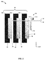
- FIG. 2 is a block diagram illustrating brake disc stack 16, an example wear measurement system 100, bracket 110 of brake assembly 10, and wear pin 50.
- wear measurement system 100 includesbracket 110,emitter 52, and sensor system 54 including controller 112 and sensor 113.
- Brake disc stack16 includes rotors 36, stators 38, and mounting brackets 102. As the individual rotors 36 and stators 38 of brake disc stack 16 wear over time, the dimension of brake disc stack 16 may decrease in the x-dimension (orthogonal x-y axes are shown are in FIG. 2 for ease of description only and do not indicate any particular orientation of brake disc stack 16 in space).
- Wear pin 50 may be coupled to any suitable portion of brake disc stack 16, such as a pressure plate (e.g., as defined by stator 38 on the end closest to bracket 110), rotor 36, or stator 38, such that as brake disc stack 16 wears, wear pin moves relative to bracket 110.
- a pressure plate e.g., as defined by stator 38 on the end closest to bracket 110
- rotor 36 e.g., as defined by stator 38 on the end closest to bracket 110
- stator 38 e.g., as defined by stator 38 on the end closest to bracket 110
- Bracket 110 may be coupled to any suitable portion of the aircraft (e.g., landing gear assembly) and does not movein the x-direction as brake disc stack 16 wears.
- emitter 52 and at least sensor 113 of sensor system 54 are configured to move relative to each other (e.g., away from or closer to each other) as brake stack 16 wears.
- emitter 52 may be mechanically connected to wear pin 50 (e.g., an end of wear pin 50 furthest from brake disc stack 16 or any other suitable location along wear pin 50) and sensor system 54 may be mechanically connected to bracket 110.
- sensor system 54 may be mechanically connected to wear pin 50 and emitter 52 is mechanically connected to bracket 110.
- emitter 52 and sensor 113 are configured to move towards each other as brake disc stack 16 wears.
- emitter 52 is configured to move towards a stationary sensor 112.
- the wear measurement system can be configured such that emitter 52 and sensor 113 are configured to move away from each other as brake disc stack 16 wears.
- Emitter 52 includes any suitable apparatus configured to emit a signal that can be sensed by sensor system 54, where a characteristic of the signal sensed by sensor 113 changes as a function of a relative distance between emitter 52 and sensor 113.
- emitter 52 and sensor 113 are configured such that a characteristic of the signal output by emitter 52 and sensed by sensor 113 indicates a distance between emitter 52 and sensor 113.
- emitter 52 includes a magnet that emits a magnetic field
- sensor 113 may include a magnetic field strength sensor, such as a magnetometer (e.g., a multi-axis magnetometer), Hall-effect sensor, or the like.
- emitter 52 includes an optical emitter (e.g., a laser) and sensor 113 may include an optical sensor.
- emitter 52 includes an acoustic emitter and sensor 113 may include an acoustic sensor; a beat frequency of a signal received by sensor 113 may indicate the relative distance between emitter 52 and sensor 113, which may indicate the level of wear of brake disc stack 16.
- Controller 112 may output a signal indicative of the beat frequency.
- emitter 52 includes a radiofrequency signal emitter (or another electrical signal emitter) and sensor 113 may include a radio transceiver.
- sensor 113 can include two antennas placed at a known distance apart (e.g., half a wavelength apart), and a controller of system 54 can determine the phase difference between signals sensed by the two or more antennas of sensor 113 in order to determine the relative distance between emitter 52 and sensor 113, which may indicate the level of wear of brake disc stack 16.
- Controller 112, a processor of external device 56, or another processor can be configured to receive the phase difference, and determine the relative distance between emitter 52 and sensor 113 based on the determined phase difference.
- controller 112 the processor of device 56, or another processor can stored information that associate different phase differences with respective different levels of brake disc stack wear. The information can be stored by, for example, a memory of controller 112, device 56, or another device
- emitter 52 include a capacitive plate (to which power can be passively applied by remote device 56) and a controller 112 can be configured to output a signal indicative of the capacitance between emitter 52 and sensor 113.
- Controller 112 a processor of external device 56, or another processor can be configured to receive the determined capacitance,and determine the relative distance between emitter 52 and sensor 113, which may indicate the level of wear of brake disc stack 16, based on the determined capacitance.
- controller 112 the processor of device 56, or another processor can stored information that associate different capacitance values with respective different levels of brake disc stack wear.
- the information can be stored by, for example, a memory of controller 112, device 56, or another device.
- a processor may receive the signal output by controller 112, determine a capacitance value based on a characteristic of the signal (e.g., an amplitude or frequency of the signal), compare the determined capacitance value to stored information, and, based on the comparison,determine the brake disc stack wear based on the wear level associated with the determined capacitance value.
- controller112 may include a processor and memory.
- the processor as well as other processors described in this disclosure, may include one or more digital signal processors (DSPs), general purpose microprocessors, application specific integrated circuits (ASICs), field programmable logic arrays (FPGAs), or other equivalent integrated or discrete logic circuitry, or combinations thereof.
- DSPs digital signal processors
- ASICs application specific integrated circuits
- FPGAs field programmable logic arrays
- the functions attributed to the controllers and processors described herein may be provided by a hardware device and embodied as software, firmware, hardware, or any combination thereof.
- controller 112 may include a transceiverconfigured to send and receive data via any suitable wirelesscommunication technique, such as, but not limited to, WiFi, Bluetooth, infrared, or radiofrequency techniques (e.g., according to the ISO 18000-2 and ISO 14443A standards).
- Controller 112 may be passively powered by an external device 56.
- controller 112 may be inductively powered by external device 56(also referred to as a remote device).
- Using a passively powered controller 112 may reduce the need to perform maintenance on controller112 because there may not be a need to run wires, or install or replace an internal power source of controller 112. Likewise, replacing the entire controller 112 may be easier because the number of connections between controller 112and the aircraft may be reduced or eliminated.
- emitter52 may be configured to emit a magnetic field (or other signal) and sensor 113 may be configured to sense the magnetic field and generate an output indicative of a characteristic of the magnetic field (e.g., a strength of the magnetic field).
- Sensor 113 may be configured to convert the electromagnetic energy of the magnetic field into a signal that can be read by controller 112. For example, sensor 113 may detect the magnetic field emitted by emitter 52 and produce a voltage proportional to the strength of the magnetic field detected at sensor 113.
- emitter 52 may include an optical emitter such as a laser configured to emit a laser beam.
- Sensor 113 may be configured to sense the laser beam and generate an output indicative of a characteristic of the laser beam (e.g., the time it takes the beam to travel between emitter 52 and sensor 113).
- Optical emitter 52 and sensor 113 may be mechanically connected to opposing structures (e.g., bracket 110 and wear pin 50) so that emitter 52 and sensor 113 move relative to each other as brake stack wears.
- optical emitter 52 and sensor 113 may be mechanically connected to the same structure (e.g., wear pin 50), such that,where optical emitter 52 emits a laser beam, the beam may reflect off another structure (e.g., bracket 110) and sensor 113 may detect the reflected beam.
- Sensor 113 may be configured to output a signal indicative of the characteristic of the emitted signal and controller 112 may receive the signal output by sensor 113.
- emitter 52 may emit a laser beam
- sensor 113 may detect the laser beam and determine the time that elapsed between when the beam was emitted and when the beam was detected, and sensor 113 may output a signal indicative of the elapsed time.
- emitter 52 may include two antennas that may be configured to emit radio frequencies (e.g., two different frequencies).
- Sensor 113 may be configured to detect the frequencies and measure the phase or beat frequency of the emitted frequencies.
- Sensor 113 may output a signal indicative of the detected frequencies such that the signal may be read by controller 112.
- Sensor 113 may be configured to continuously sense the signal output by emitter 52 or detect the signal at regular or irregular periodic intervals (e.g., once per day, after every landing, and the like). In some examples, sensor 113 may be configured to generate the output indicative of the characteristic of the signal on demand, such as when a field technician performs an inspection using remote device 56 and wirelessly interrogates sensor system 54 by wirelessly providing power to controller 112. Sensor 113 may be configured to sense the signal output by emitter 52 and generate an output indicative of the sensed signalonly when brake disc stack 16 is compressed or only when brake disc stack 16 is uncompressed.
- controller 112 may receive a signal from sensor 113 shortly after being powered-up via the energy emitted by external device 56.
- sensor 113 may detect a magnetic field and produce a voltage (or another suitable output), and controller 112 may receive the voltage from sensor 113 immediately upon power-up.
- emitter 52 and sensor 113 may both be wirelessly powered via external device 56.
- powering emitter 52 and sensor 113 via the same wireless power source may provide resilience to interference, e.g., compared to examples in which emitter 52 passively emits a magnetic field.
- wirelessly powering both emitter 52 and sensor 113 may help maintain the calibration between emitter 52 and sensor 113.
- wirelessly powering both emitter 52 and sensor 113 may also provide a facility for radiofrequency (RF) transmission techniques, such as modulated codes and identifiers, to be employed by emitter 52.
- RF radiofrequency
- Brake disc stack 16 may become worn due to friction between rotors 36 and stators38.
- wear pin 50 may move relative to bracket 110.
- One of sensor 113 or emitter 52 is coupled to wear pin 108, such that one of sensor 113 or emitter 52 moves with wear pin 50 as brake disc stack 16 wears.
- emitter 52 and sensor 113 may be configured to move relative to one another (e.g., emitter 52 may be coupled to wear pin 108 and sensor 113 may be coupled to bracket 110, or vice versa).
- emitter 52 may be coupled to the end of wear pin 50 furthest from brake disc stack 16. In this example, as brake disc stack 16 wears down, wear pin 50 and emitter 52 move towards bracket 110 (e.g., to the left in FIG. 2 ).
- a characteristic of the signal (e.g., the strength of a magnetic field, or time elapsed between when a laser beam was emitted and when it was sensed) generated by emitter 52 and sensed by sensor 113 may change.
- the characteristic of the signal may change as a function of the amount of wear of brake disc stack 16 and may be used by controller 112 or remote device 56, or both, to determine the amount of wear of brake disc stack 16.
- emitter 52 moves towards bracket 110 as brake disc stack 16 wears, such that, if emitter 52 is a magnet, the magnetic field at sensor 113 becomes strongeras brake disc stack 16 wears.
- emitter 52 may be coupled to wear pin 50 between bracket 110 and brake disc stack 16. In these examples, as brake disc stack 16 wears, emitter 52 moves away from bracket 110 (e.g., to the left in FIG. 2 ), such that, if emitter 52 is a magnet,the magnetic field at sensor 113 becomes weaker as brake disc stack 16 wears.
- sensor 113 is configured to sense the signal output by emitter 52and generate an output indicative of a characteristic of the signal. For example, if emitter 52 is a magnet, sensor 113 may output a voltage proportional to the strength of the magnetic field at sensor 113.
- controller 112, remote device 56, or another device may determine an amount of wear of brake disc stack 16 based on the output generated by sensor 113.
- the amount of wear of brake disc stack 16 can be any suitable parameter indicative of the state of wear of brake disc stack 16.
- the amount of wear of brake disc stack 16 is a measurement of the amount (e.g., a distance) brake disc stack 16 has worn in the x-axis direction relative to a predetermined baseline.
- the predetermined baseline can be stored by controller 112, remote device 56, or another device, and can be, for example, a starting measurement (in dimensions of length) when the brake disc stack 16 was installed or any other prior measurement.
- controller 112, remote device 56, or another device may receive the output generated by sensor 113(e.g., a voltage) and determine a distance between emitter 52 and sensor 113 based on the output. The distance may increase or decrease (depending on the particular configuration of the wear measurement system) as brake disc stack 16 wears.A characteristic of the signal received by sensor 113 (e.g., the strength of the magnetic field) may correspond to a distance between emitter 52 and sensor 113. Likewise, the output from sensor 113 (e.g,. a voltage) may be proportional to the signal received by sensor 113 (e.g., strength of the magnetic field). In some examples, emitter 52 includes a magnet and the strength of the magnetic field received by sensor 113 may be associated with a voltage level.
- controller 112, remote device 56, or another device may store a table or other data structure that associates a plurality of different voltage levels with respective distances between emitter 52 and sensor 113. In some examples, controller 112, remote device 56, or another device may then determine the distance between emitter 52 and sensor 113 based on the voltage output by sensor 113 by determining the distance associated with the voltage in the data structure.
- the amount of wear of brake disc stack 16 can be a percentage of usable life of brake disc stack 16 remaining.
- emitter 52 includes a magnet
- a plurality of different percentages of remaininguseable life of brake disc stack 16 may be associated with respective magnetic field characteristics in a memory of controller 112, remote device 56, or another device, such that once the magnetic field characteristic is determined, controller 112 or a processor of remote device 56 may determine the percentage of useable life of brake disc associated with the magnetic field characteristic can be determined.
- controller 112 may determine the remaining useable lifespan of brake disc stack 16 based on the determined distance between emitter 52 and sensor 113.
- controller 112 or another device such as remote device 56, may store a table or other data structure that associates different distances (or, in some examples, voltages generated by sensor 113) with different amounts of wear.
- Controller 112 or the other device may then determine an amount of wear (e.g., as indicated by percentage of a usable life remaining or used up) by determining the amount of wear associated with the output generated by sensor 113.
- controller 112 may merely output the voltage (or other electrical signal characteristic) generated by sensor 113 to external device 56, and a processor of external device 56 may determine an amount of wear of brake disc stack 16 based on the output generated by sensor 113 and transmitted by controller 112, e.g., using any of the techniques described above with respect to controller 112.
- FIG. 3 is a block diagram illustrating another example wear measurement system 150, which is similar to wear measurement system 100 shown in FIG. 2 , but shows a different placement of emitter 52, controller 112, and sensor 113. Instead of one of emitter 52 or sensor 113 being mechanically connected to wear pin 50 (shown in FIG. 2 ), in the example shown in FIG.
- emitter 52 is mechanically connected to brake disc stack 16and sensor 112 is mechanically connected to bracket 110.
- emitter 52 can be connected to stator 38 at an end of stack 38, which may act as a pressure plate for brake disc stack 16 (against which an actuator applies a force to compress brake disc stack 16).
- emitter 52 can be mechanically connected to bracket 110 and sensor 113 can be mechanically connected to brake disc stack 16.
- a distance between a surface of brake disc stack 16 and bracket 110 may increase as rotors36and stators 38 are worn.
- Wear measurement system 150 is configured such that as brake disc stack 16 wears and decreases dimension in the negative x-axis direction (orthogonal x-y axes are shown in FIG. 3 for ease of description only), emitter 52 and sensor 112 move away from each other, rather than towards each other as in the example of wear measurement system 100 shown in FIG. 2 . Accordingly, as brake disc stack 16 wears, emitter 52may move away from sensor 113such that a characteristic of the signal at sensor 113 changes as brake disc stack 16 wears.
- emitter 52 may move away from sensor 113 such that magnetic field strength at sensor 113 decreases as brake disc stack 16 wears.
- emitter 52 includes an optical emitter (e.g., a laser)
- emitter 52 may move away from sensor 113 such that the time between when emitter 52 emits a signal (e.g., a laser beam) and when the signal is detected by sensor 113 may increase as brake disc stack 16 wears.
- a signal e.g., a laser beam
- emitter 52 and sensor 113 may both be mechanically connected to either bracket 110 or brake disc stack 16.
- emitter 52 and sensor 113 may be mechanically connected to bracket 110 such that the laser beam reflects off brake disc stack 16 and the reflected beam is detected by sensor 113.
- controller 112 a processor of remote device 56, or another component of wear measurement system 150 may be configured to determine the amount of wear of brake disc stack 16 based on an output generated by sensor 113 using any of the techniques described above, e.g., with respect to FIG. 2 .
- FIG. 4 is a conceptual and block diagram illustrating an example wear measurement system 200, which can be an example of system 100 of FIG. 2 or system 150 of FIG. 3 .
- Wear management system 200 may include controller 112, sensor 113, emitter 52, and remote device 56.
- controller 112 includesprocessor 212, memory 214, transceiver 216, and power receiver 218.
- Transceiver 216 is configured to support wireless communication between controller 112 and an external device, such as remote device 56.
- processor 212 may transmit information indicative of a characteristic of a signal sensed by sensor 113 (e.g., raw sensor outputs or parameterized sensor output) to remote device 56.
- processor 212 may determine an amount of brake disc stack 16 wear determined based on an output of sensor 113 and transmit the determined amount of brake disc stack 16 wear to remote device 56 via transceiver.
- Processor 212 may also receive other information from remote device 56 or another device via transceiver216, such as updates to software implemented by processor 212 to determine an amount of brake disc stack 16 wear or to make other determinations.
- Power receiver 218 may include an antenna configured to receive inductive power generated by remote device 56.
- power receiver 218 may include other components configured to convert the inductively received power into useful energy for powering controller 112, such as, but not limited to, one or more capacitors, one or more, rectifiers or one or more DC-DC charge pumps.
- Remote device 56 may include a power transmitter configured to generate and emit energy (e.g., electromagnetic waves) that induces a current in the antenna of power receiver 218.
- energy e.g., electromagnetic waves
- power receiver 218 enables controller 112 to be passively powered by electromagnetic induction, such that controller 112 does not include wires running to controller 112 from a power source or an internally housed power source.
- a passively powered controller 112 may make it easier to install, operate, and maintain wear measurement system 200.
- controller 112 that is passively powered and does not include an internal power source may be more compact relative to a controller that includes a power source. The more compact design may be easier to install in the relatively tight spaces available in an aircraft brake assembly.
- power receiver 218 may include a wired connection so that controller 112 may be powered using batteries or wires.
- processor 212 may control transceiver 216 to transmit an indication of a characteristic of a signal sensed by sensor 113. This may be, for example, a real-time sensor output, at the time controller 112 is powered.For example, processor 212 may control transceiver 216 to transmit a raw electrical signal output by sensor 113 or a parameterized signal (e.g., a voltage level determined based on the raw electrical signal output by sensor 113). In this way, remote device 56 may be configured to interrogate sensor system 54 by transmitting energy that powers controller 112 and causes controller 112 to transmit an indication of a characteristic of a signal sensed by sensor 113.
- a parameterized signal e.g., a voltage level determined based on the raw electrical signal output by sensor 113.
- remote device 56 may include processor 222, memory 224, transceiver 226, and power supplier 228.
- remote device 56 may is a handheld device, such as mobile computing device (e.g., smartphone, tablet, and the like).
- a handheld device may permit device 56 to be relatively portable, which may increase the usefulness of wear measurement system 200 in the field, e.g., during a regular aircraft maintenance event.
- Transceiver 216 is configured to support wireless communication between remote device 56 and controller 112.
- Power supplier 228 is configured to generate and emit energy (e.g., electromagnetic waves) that power controller 112.
- Power supplier 228 may provide power to controller 112 without using cables or wires, for example, using inductive power to emit an electromagnetic field that may be received by the power receiver 218 of controller 112.
- emitter 52 may emit a signal (e.g., a magnetic field) that is sensed by sensor 113.
- Controller 112 may be passively powered by remote device 56 when an amount of wear of brake disc stack 16 is desired. For example, a technician may position remote device 56 proximate to controller 116 and control device 56 to emit electromagnetic energy to power controller 112. The energy may energize power receiver 218 of controller 112 and cause controller 112 to activate.
- power supplier 228 is configured to generate a 824 megaherz (MHz) to about 960 MHz signal having a power of about 8 Decibel-milliwatts (dBm) to about 17 dBm, which may enable power receiver 218 to charge within one second of being exposed to the signal if device 56 is held within one meter of power receiver 218, or within 100 seconds if device 56 is held 10 meters from power receiver 218.
- MHz 824 megaherz
- 960 MHz signal having a power of about 8 Decibel-milliwatts (dBm) to about 17 dBm
- processor 212 may receive an output generated by sensor 113, where the output varies as a function of a characteristic of the signal emitted by emitter 52.
- sensor 113 may generate an output (e.g., a voltage) that indicates a characteristic of a signal (e.g., the strength of a magnetic field)emitted by emitter 52.
- controller112 may receive the output from sensor 113 and, in some examples, may transmit an indication of the output (e.g., the raw output itself or a parameterized output, such as a magnitude of the voltage) to remote device 56 via the respective transceivers 216, 226.
- processor 212, processor 222, or both processors 212, 222 determine an amount of wear of brake disc stack 16 based on the output generated by sensor 113.
- the voltage output (or other output) generated by sensor 113 may be proportional to a characteristic of the signal (e.g., the magnetic field strength) sensed by sensor 113, which may itself be proportional to the distance between emitter 52 and sensor 113.
- the distance between emitter 52 and sensor 113 may be proportional to the amount of wear of the brake disc stack 16.
- Processor 222 may store the information received from controller 112 in memory 224.
- the information can include, for example, sensor outputs, determined amounts of brake disc stack 16 wear, and the like.
- processor 222 may store the determined amounts in memory 224.
- the amount of brake disc stack wear can be any suitable quantification of wear, such as, but not limited to, a magnitude of wear (e.g., measured in units of length) relative to a predetermined baseline, the remaining useable lifespan of brake disc stack 16 as a percentage of wear or a magnitude remaining, or any combination thereof.
- processor 222 may be configured to determine whether the amount of wear determined based on the output of sensor 113 indicates maintenance of brake assembly 10 is advisable. For example, in response to determining the amount of brake disc stack 16 wear is less than or equal to a threshold value (stored by memory 224), processor 222 may generate a notification to a user. The notification may indicate, for example, that a particular wear level was detected (e.g., less than 25% of useful brake disc stack 16life is remaining).
- the notification can be, for example, a visual notification (e.g., presented via a display or other visual indicator, such as activation of a light, of remote device 56), an audible notification, or a somatosensory notification (e.g., the handheld device may vibrate to provide the notification).
- a visual notification e.g., presented via a display or other visual indicator, such as activation of a light, of remote device 56
- an audible notification e.g., the handheld device may vibrate to provide the notification
- a somatosensory notification e.g., the handheld device may vibrate to provide the notification.
- the user may perform any desired maintenance, such as replacement of one or more rotors 36 or stators 38.
- processor 222 may store a plurality of determined amounts of brake disc stack 16 wear in memory 224, each amount being measured at a different time, and associate the determined amounts of wear with the particular brake assembly 10 in memory 224.
- remote device 56 may also upload the values to a remote database via transceiver 226 or another communications module. Another device may then access historical wear information, which may be useful for analyzing the wear pattern of brake assembly 10, the wear pattern of brakes for a particular aircraft, a particular type of aircraft, a particular type of brake assembly, and the like.
- processor 222 may be configured to predict when one or more rotors 36 or stators 38 may need to be replaced based on the output of sensor 113. For example, based on historical wear data for the particular brake assembly 10, processor 222 may determine the rate of wear of brake disc stack 16 and predict the number of landings until the amount of wear is less than or equal to a predetermined threshold wear level. In this way, wear measurement system 200 may not only be used to obtain real-timebrake disc stack 16 measurements, but may also be used to plan brake assembly 10 maintenance. This may improve the maintenance scheduling and workflow by allowing an entity (e.g., a maintenance facility) to anticipate when brake disc stack 16 will need to be replaced and have parts readily available.
- an entity e.g., a maintenance facility
- Memory 214 and memory222 may include any one or more volatile or non-volatile media, such as a random access memory (RAM), read only memory (ROM), non-volatile RAM (NVRAM), electrically erasable programmable ROM (EEPROM), flash memory, and the like.
- Memories 214, 222 may store computer-readable instructions that, when executed by the respective processors 212, 222 cause controller 112 and remote device 56, respectively, to perform various functions described herein.
- FIG. 5 is a flow diagram illustrating an example method of determining an amount of wear of a brake disc stack of a brake assembly. For purposes of illustration only, the example method will be described with reference to brake assembly 10 and the wear measurement system described in FIG. 4 . However, the method may apply to other wear measurement systems.
- power supplier 228 of remote device 56 may wirelessly transmit power to controller 112, which may wirelessly receive the power from remote device 56 via power receiver 218 (302).
- Processor 222 may receive an output from sensor 113 (304), which is configured to sense a signal (e.g., a magnetic field) emitted by from emitter 52and generate an output indicative of a characteristic of the sensed signal.
- sensor 113 may sense a magnetic field and output a voltage proportional to the strength of the magnetic field.
- Processor 212 of controller 112 may receive the signal output by sensor 113 and control transceiver 216 to transmit information indicative of the sensor output or a determined level of brake disc stack 16 wear to remote device 56 (306).
- processor 212 receives the output from sensor 113,determines a voltage value based on the signal (e.g., the magnitude of the voltage), and transmits the voltage value to remote device 56.
- Processor 212 of controller 112 or processor 222 of remote device 56 may determine the amount of wear of brake disc stack16 based on output generated by sensor 113 using any of the techniques described above.
- the techniques of this disclosure may be implemented in a wide variety of computing devices. Any components, modules or units have been described provided to emphasize functional aspects and does not necessarily require realization by different hardware units.
- the techniques described herein may be implemented in hardware, software, firmware, or any combination thereof. Any features described as modules, units or components may be implemented together in an integrated logic device or separately as discrete but interoperable logic devices. In some cases, various features may be implemented as an integrated circuit device, such as an integrated circuit chip or chipset.
- the techniques of this disclosure may also be implemented on an article of manufacture comprising a computer-readable storage medium.
- the term "processor,” as used herein may refer to any of the foregoing structure or any other structure suitable for implementation of the techniques described herein.
- the functionality described herein may be provided within dedicated software modules or hardware modules configured for performing the techniques of this disclosure. Even if implemented in software, the techniques may use hardware such as a processor to execute the software, and a memory to store the software. In any such cases, the devices described herein may define a specific machine that is capable of executing the specific functions described herein. Also, the techniques could be fully implemented in one or more circuits or logic elements, which could also be considered a processor.
Landscapes
- Engineering & Computer Science (AREA)
- General Engineering & Computer Science (AREA)
- Mechanical Engineering (AREA)
- General Physics & Mathematics (AREA)
- Physics & Mathematics (AREA)
- Chemical & Material Sciences (AREA)
- Transportation (AREA)
- Chemical Kinetics & Catalysis (AREA)
- Life Sciences & Earth Sciences (AREA)
- Analytical Chemistry (AREA)
- Biochemistry (AREA)
- General Health & Medical Sciences (AREA)
- Health & Medical Sciences (AREA)
- Immunology (AREA)
- Pathology (AREA)
- Electrochemistry (AREA)
- Braking Arrangements (AREA)
Abstract
Description
- This disclosure relates to vehicle braking systems, such as an aircraft braking assembly.
- A brake assembly of an aircraft or another vehicle has a limited useable life, as determined through wear, and may have an associated operating and maintenance cost that is based on the actual use of the brake assembly and how fast the life of the brake assembly is consumed. As a result of varying external factors and varying frictional forces during braking events, different brake assemblies may experience different rates of wear over time.
- Devices, systems, and techniques for determining an amount of wear of a brake disc stack of a brake assembly, such as an aircraft brake assembly, are described herein.In some examples, a brake wear measurement system includes anemitter configured to emit a signal and a passive powered sensor system including a controller and a sensor configured to sense the signal emitted by the emitter. In some examples, the emitter includes a magnetic field emitter and the sensor includes a magnetic field strength sensor. The emitter and the sensor of the sensor system are mounted on the brake assembly such as the emitter and the sensor may be configured to move relative to each other as the brake disc stack wears. Thus, a characteristic of the signal emitted by the emitter and sensed by the sensor may change as a function of the brake disc stack wear. The brake wear measurement may further include a processor configured to receive the output generated by the sensor and determine, based on the output, an amount of wear of the brake disc stack assembly. The amount of wear (or "level" of wear) can be, for example, a percentage of useful life of the brake disc stack remaining, a magnitude of wear (e.g., as measured in units of length), or any other suitable quantification of the amount of wear. In some examples, the processor may reference a data structure that associates sensor outputs with the amount of brake disc stack wear in order to determine the amount of wear indicated by a particular sensor output.
- In one example, the disclosure is directed to a system comprising a brake disc stack and an emitter configured to emit a signal. The system further includes a sensor configured to sense the emitted signal, generate an output indicative of a characteristic of the sensed signal, wherein the sensor and the emitter are configured to move relative to each other as the brake disk stack wears. The system further includes a passively powered controller operatively coupled to the sensor and configured to wirelessly receive power from a remote device, receive the output generated by the sensor, and a processor configured to determine an amount of wear of the brake disc stack based on the output generated by the sensor. The controller may be configured to transmit, to the remote device, at least one of: information indicative of the output generated by the sensor or the amount of wear of the brake disc stack determined based on the output.
- In another example, the disclosure is directed to a method comprising emitting, by an emitter, a signal, and detecting, by a sensor, the signal emitted by the emitter. The method includes generating, by the sensor, an output indicative of a characteristic of the signal emitted by the emitter, and wirelessly receiving, by a passively powered controller, power from a remote device. The method further includes receiving, by the passively powered controller, the output generated by the sensor, and determining an amount of wear of a brake disc stack based on the output generated by the sensor.
- In another example, the disclosure is directed to a system comprising means means for emitting, by an emitter, a signal, and means for detecting, by a sensor, the signal emitted by the emitter. The system includes means for generating, by the sensor, an output indicative of a characteristic of the signal emitted by the emitter, and means for wirelessly receiving, by a passively powered controller, power from a remote device. The system further includes means for receiving, by the passively powered controller, the output generated by the sensor, and means for determining an amount of wear of a brake disc stack based on the output generated by the sensor.
- The disclosure is also directed to an article of manufacture comprising a computer-readable storage medium. The computer-readable storage medium comprises computer-readable instructions that are executable by a processor. The instructions cause the processor to perform any part of the techniques described herein. The instructions may be, for example, software instructions, such as those used to define a software or computer program. The computer-readable medium may be a computer-readable storage medium such as a storage device (e.g., a disk drive, or an optical drive), memory (e.g., a Flash memory, read only memory (ROM), or random access memory (RAM)) or any other type of volatile or non-volatile memory or storage element that stores instructions (e.g., in the form of a computer program or other executable) to cause a processor to perform the techniques described herein. The computer-readable medium may be a non-transitory storage medium.
- The details of one or more examples are set forth in the accompanying drawings and the description below. Other features, objects, and advantages of the disclosure will be apparent from the description and drawings, and from the claims.
-
-
FIG. 1 is a schematic diagram illustrating an example aircraft brake assembly and an example wear measurement system. -
FIG. 2 is a conceptual diagram illustrating an example wear measurement system. -
FIG. 3 is a conceptual diagram illustrating another example wear measurement system. -
FIG. 4 is a block diagram illustrating an example wear measurement system. -
FIG. 5 is a flow diagram illustrating an example method of measuring an amount of wear of a brake disc stack of a brake assembly using a measurement system. - Example devices, systems, and techniques for determining an amount of wear of a brake disc stack of a brake assembly are described herein. In some examples, a brake wear measurement system includes anemitter and a passive powered sensor system including a controller and a sensor. The emitter and at least the sensorof the sensor system are mounted on the brake assembly such the emitter and sensor may be configured to move relative to each other as the brake disc stack wears. For example, one of the emitter or the sensor may be mounted on a bracket and may remain stationary as the brake disc stack wears, and the other of the emitter or the sensor may be configured to move with the brake disc stack as it wears (e.g., on a wear pin or a pressure plate of the brake disc stack).
- The emitter and the sensor may not be electrically coupled to each other via wire. In some examples, as the emitter and the sensor move towards or away from each other as the brake disc stack wears, a characteristic of the signal emitted by the emitter and sensed by the sensor may change as a function of the brake disc stack wear. A processor may receive, from the sensor assembly,an indication of the characteristic of the signal sensed by the sensor and determine an amount of brake disc stack wear based on the characteristic of the signal sensed by the sensor. For example, the emitter may include a magnet that emits a magnetic field, and different levels of brake disc stack wear may be associated with different magnetic field characteristics, e.g., in a mapping table or other data structure, and the processor may compare the received magnetic field characteristic to the data structure to determine the brake disc stack wear. As an example, the magnetic field characteristics may be associated with values corresponding to a distance between the field emitter and the sensor, which may change as a function of the amount of brake disc stack wear. The processor can be a part of the sensor assembly mounted on the aircraft brake assembly or can be part of a remote device, separate from and not wired to the sensor assembly.
- The emitter, the sensor system, or both the emitter and sensor system may be passively powered. For example, rather than including a power source, the sensor system may be passively powered by the remote device. The remote device may emit energy (e.g., electromagnetic waves)that powers the sensor system, and, in response to being powered, the sensor system may transmit an indication of a characteristic of the signal sensed by the sensor or an amount of brake disc wear determined based on the characteristic of the signal sensed by the sensor.Likewise, in some examples, if the emitter requires power, the emitter may be powered by the remote device.In some examples, the remote device receives the indication of the characteristic of the signal and determines the amount of brake disc stack wear based on the received indication.
- The passive powering of the sensor system, as well as the wireless data path between the sensor system and the remote device may provide certain advantages in some examples. An aircraft brake assembly may be exposed to relatively hostile environmental conditions (e.g., corrosive deicing fluids on a runway), and running wires to power to a wear measurement system mounted on the aircraft brake assembly may pose challenges.For example, the wires may be subject to the same hostile environmental conditions as the brake assembly, and may corrode or otherwise wear relatively fast, thereby decreasing the useful life of the wear measurement system. The passive powering of the wear measurement system described herein may reduce the number of wires, if not eliminate all wire, connecting the wear measurement system to power sources, and, therefore, may be more robust and longer lasting than wired wear measurement systems.
- The wear level of a brake disc stack may be determined using the devices, systems, and techniques herein without requiring a technician to manually push in a wear pin, visually inspect the wear pin and make a subjective determination as to wear level, and the like. Instead, the technician or other user may only need to walk around the landing gear with a remote device,interrogate each sensor system mounted on the aircraft brake assemblies with the remote device (e.g., by powering the sensor system via the remote device), and read or otherwise receive an amount of wear automatically determined by the sensor system or the remote device. In this way, the devices, systems, and techniques for determining an amount of wear of a brake disc stack assembly may decrease turn around time for determining the wear amount compared to other proposed systems.
- Existing brake disc stack wear measurement devices, systems, and techniques may also not record, collect, or display the measurement data in a meaningful way. In contrast, in some examples described herein, brake disc stack wear measurements for a particular brake assembly may be stored, e.g., which may enable patterns of wear to be determined, and for replacement parts to be ordered. The preordering of replacement parts may help reduce the amount of time the aircraft (or other vehicle) is out of commission for maintenance purposes.
- While aircraft brake assemblies are primarily referred to herein for ease of description, the example brake disc stack wear measurement devices, systems, and techniques described herein may be used with brake assemblies of other vehicles, the brake assemblies including a brake disc stack the wears with brake usage.
-
FIG. 1 is a schematic diagram illustrating an example aircraft brake assembly that includes a wear measurement system, in accordance with one or more examples described herein.In the example shown inFIG. 1 , aircraft brakeassembly 10includes wheel 12,actuator assembly 14,brake disc stack 16, andaxle 18.Wheel 12 includeswheel hub 20, wheel outrigger flange 22,lug bolt 26, andlug nut 28.Actuator assembly 14 comprisesactuator housing 30,actuator housing bolt 32, and a plurality of pistons (not labeled). Wheel outriggerflange 22 is mechanically affixed towheel hub 20 bylug bolts 26 and lug nuts 28.During assembly, an inflatable tire (notshown) may be placed overwheel hub 20 and secured on an opposite side by wheel outrigger flange 22. Thereafter, lugnuts 28 can be tightened on lug bolts26, and the inflatable tire can be inflated. -
Assembly 10 may be mounted to an aircraft viatorque tube 42 andaxle 18. In the example ofFIG. 1 ,torque tube 42 is affixed toaxle 18 by a plurality ofbolts 46.Torque tube 42supports actuator assembly 14 andstators 38 of brake disc stack 16.Axle 18 may be mounted on a strut of a landing gear (not shown) to connect theassembly 10 to an aircraft.During operation of the aircraft, braking may be necessary from time totime, such as during landing and taxiing. Accordingly,aircraft brake assembly 10 maysupport braking throughactuator assembly 14 andbrake disc stack 16. During operation, pistons ofactuator assembly 14 mayextend away fromactuator housing 30 to axially compress brake disc stack16against compression point 48 to provide braking. -
Brake disc stack 16 includes alternatingrotor discs 36 andstator discs 38.Rotor discs 36 are mounted towheel 12, and inparticular wheel hub 20, bybeam keys 40. Stator discs are mounted toaxle 18, and inparticular torque tube 42, by splines 44.In the example ofFIG. 1 ,brake disc stack 16 includes fourrotors 36 and fivestators 38. However, a different number of rotors and/or stators may be included inbrake disc stack 16. Further, the relative positions of the rotors and stators may be reverse,e.g., such thatrotor discs 36 are mounted totorque tube 42 andstator discs 38 are mounted towheel hub 20. -
Rotor discs 36 andstator discs 38 may be mounted inassembly 10 bybeam keys 40 andsplines 44, respectively.Beam keys 40 may becircumferentially spaced about an inner portion ofwheel hub 20. Beam keys 40maybe shaped with opposing ends (e.g., opposite sides of a rectangular) and may haveone end mechanically affixed to an inner portion ofwheel hub 20 and an oppositeend mechanically affixed to an outer portion ofwheel hub 20.Beam keys 40 maybe integrally formed withwheel hub 20 or may be separate from and mechanicallyaffixed towheel hub 20, e.g., to provide a thermal barrier between rotor discs36and wheel hub 20. -
Splines 44 may be circumferentially spaced about an outerportion oftorque tube 42.Splines 44 may be integrally formed withtorque tube 42 or may beseparate from and mechanically affixed totorque tube 42. In some examples,splines 44 may define lateral grooves intorque tube 42. As such, stator discs 38may include a plurality of radially inwardly disposed notches configured to beinserted into a spline. -
Brake assembly 10 includes a wear measurement system, which, in the example shown inFIG. 1 ,includeswear pin 50,emitter 52,sensor system 54, andremote device 56. As described in further detail with respect toFIG. 2 ,emitter 52 is configured to emit a signal and a sensor ofsensor system 54 may be configured to generate an output indicative of a characteristic of the signal, such as the signal strength.Sensor system 54 may further comprise a controller configured to receive the output generated by the sensor, and wirelessly transmit an indication of thecharacteristicof the signal (determined based on the sensor output) toremote device 56. In some examples, the controller ofsensor system 54 or a processor of remote device 56may determine an amount of wear of brake disc stack 16 (e.g., relative to a predetermined state in which stack 16 was less worn) based on the indication of the characteristic of the signal. The indication can be, for example, a value or other parameter that varies as a function of the characteristic of the signal. For example, the indication can be the raw output fromsensor 113 or a value determined based on the raw output. - In the example shown in
FIG. 1 ,sensor system 54 andemitter 52 are selected to be robust and suitable for use in the relatively harsh operating environment ofbrake assembly 10. For example, the components ofsensor system 54 andemitter 52 may be selected to be able to operate in environments up to 300 degrees Fahrenheit (about 150 degrees Celsius), as well as in environments that may be subject to ice, shock, and vibration. - As shown in
FIG. 1 ,remote device 56 is configured to transmit electromagnetic energy or the like that passively powerssensor system 54. When powered,sensor system 54 may transmit an indication of the characteristic of the signalsensed bysensor 113 toremote device 56. In this way,remote device 56 may wirelessly powersensor system 54, such thatsensor system 54 may not include a power source (e.g., a battery) and may not be connected to a power source, e.g., via wires running throughbrake assembly 10. Likewise, in some examples,remote device 56 may wirelessly poweremitter 52. -
FIG. 1 illustrates anexample brake assembly 10. In other examples, the wear measurement system described herein may be used with other brake assemblies having other configurations. -
FIG. 2 is a block diagram illustratingbrake disc stack 16, an examplewear measurement system 100,bracket 110 ofbrake assembly 10, and wearpin 50. In the example shown inFIG. 2 , wearmeasurement system 100includesbracket 110,emitter 52, andsensor system 54 includingcontroller 112 andsensor 113. Brake disc stack16 includesrotors 36,stators 38, and mountingbrackets 102. As theindividual rotors 36 andstators 38 ofbrake disc stack 16 wear over time, the dimension ofbrake disc stack 16 may decrease in the x-dimension (orthogonal x-y axes are shown are inFIG. 2 for ease of description only and do not indicate any particular orientation ofbrake disc stack 16 in space).Wear pin 50 may be coupled to any suitable portion ofbrake disc stack 16, such as a pressure plate (e.g., as defined bystator 38 on the end closest to bracket 110),rotor 36, orstator 38, such that asbrake disc stack 16 wears, wear pin moves relative tobracket 110. -
Bracket 110 may be coupled to any suitable portion of the aircraft (e.g., landing gear assembly) and does not movein the x-direction asbrake disc stack 16 wears. - In some examples,
emitter 52 and atleast sensor 113 ofsensor system 54 are configured to move relative to each other (e.g., away from or closer to each other) asbrake stack 16 wears. As shown inFIG. 2 , in one example,emitter 52 may be mechanically connected to wear pin 50 (e.g., an end ofwear pin 50 furthest frombrake disc stack 16 or any other suitable location along wear pin 50) andsensor system 54 may be mechanically connected tobracket 110. However, in other examples,sensor system 54 may be mechanically connected to wearpin 50 andemitter 52 is mechanically connected tobracket 110. In addition, in the example shown inFIG. 2 ,emitter 52 andsensor 113 are configured to move towards each other asbrake disc stack 16 wears. In particular,emitter 52 is configured to move towards astationary sensor 112. In other examples, as described with respect toFIG. 3 , the wear measurement system can be configured such thatemitter 52 andsensor 113 are configured to move away from each other asbrake disc stack 16 wears. -
Emitter 52 includes any suitable apparatus configured to emit a signal that can be sensed bysensor system 54, where a characteristic of the signal sensed bysensor 113 changes as a function of a relative distance betweenemitter 52 and sensor 113.Thus,emitter 52 andsensor 113 are configured such that a characteristic of the signal output byemitter 52 and sensed bysensor 113 indicates a distance betweenemitter 52 andsensor 113. For example, in some examples,emitter 52 includes a magnet that emits a magnetic field, andsensor 113 may include a magnetic field strength sensor, such as a magnetometer (e.g., a multi-axis magnetometer), Hall-effect sensor, or the like. In other examples,emitter 52 includes an optical emitter (e.g., a laser) andsensor 113 may include an optical sensor. In other examples,emitter 52 includes an acoustic emitter andsensor 113 may include an acoustic sensor; a beat frequency of a signal received bysensor 113 may indicate the relative distance betweenemitter 52 andsensor 113, which may indicate the level of wear ofbrake disc stack 16.Controller 112 may output a signal indicative of the beat frequency. - As another example,
emitter 52 includes a radiofrequency signal emitter (or another electrical signal emitter) andsensor 113 may include a radio transceiver. For example,sensor 113 can include two antennas placed at a known distance apart (e.g., half a wavelength apart), and a controller ofsystem 54 can determine the phase difference between signals sensed by the two or more antennas ofsensor 113 in order to determine the relative distance betweenemitter 52 andsensor 113, which may indicate the level of wear of brake disc stack 16.Controller 112, a processor ofexternal device 56, or another processor can be configured to receive the phase difference, and determine the relative distance betweenemitter 52 andsensor 113 based on the determined phase difference. For example,controller 112, the processor ofdevice 56, or another processor can stored information that associate different phase differences with respective different levels of brake disc stack wear. The information can be stored by, for example, a memory ofcontroller 112,device 56, or another device - As another example,
emitter 52 include a capacitive plate (to which power can be passively applied by remote device 56) and acontroller 112 can be configured to output a signal indicative of the capacitance betweenemitter 52 andsensor 113.Controller 112, a processor ofexternal device 56, or another processor can be configured to receive the determined capacitance,and determine the relative distance betweenemitter 52 andsensor 113, which may indicate the level of wear ofbrake disc stack 16, based on the determined capacitance. For example,controller 112, the processor ofdevice 56, or another processor can stored information that associate different capacitance values with respective different levels of brake disc stack wear. The information can be stored by, for example, a memory ofcontroller 112,device 56, or another device.A processor may receive the signal output bycontroller 112, determine a capacitance value based on a characteristic of the signal (e.g., an amplitude or frequency of the signal), compare the determined capacitance value to stored information, and, based on the comparison,determine the brake disc stack wear based on the wear level associated with the determined capacitance value. - As described with respect to
FIG. 4 , controller112 may include a processor and memory.The processor, as well as other processors described in this disclosure, may include one or more digital signal processors (DSPs), general purpose microprocessors, application specific integrated circuits (ASICs), field programmable logic arrays (FPGAs), or other equivalent integrated or discrete logic circuitry, or combinations thereof. The functions attributed to the controllers and processors described herein may be provided by a hardware device and embodied as software, firmware, hardware, or any combination thereof. - In some examples,
controller 112 may include a transceiverconfigured to send and receive data via any suitable wirelesscommunication technique, such as, but not limited to, WiFi, Bluetooth, infrared, or radiofrequency techniques (e.g., according to the ISO 18000-2 and ISO 14443A standards).Controller 112 may be passively powered by anexternal device 56. For example,controller 112 may be inductively powered by external device 56(also referred to as a remote device). Using a passivelypowered controller 112 may reduce the need to perform maintenance on controller112 because there may not be a need to run wires, or install or replace an internal power source ofcontroller 112. Likewise, replacing theentire controller 112 may be easier because the number of connections between controller 112and the aircraft may be reduced or eliminated. - In operation, in some examples, emitter52 may be configured to emit a magnetic field (or other signal) and
sensor 113 may be configured to sense the magnetic field and generate an output indicative of a characteristic of the magnetic field (e.g., a strength of the magnetic field).Sensor 113 may be configured to convert the electromagnetic energy of the magnetic field into a signal that can be read bycontroller 112. For example,sensor 113 may detect the magnetic field emitted byemitter 52 and produce a voltage proportional to the strength of the magnetic field detected atsensor 113. - In some examples,
emitter 52 may include an optical emitter such as a laser configured to emit a laser beam.Sensor 113 may be configured to sense the laser beam and generate an output indicative of a characteristic of the laser beam (e.g., the time it takes the beam to travel betweenemitter 52 and sensor 113).Optical emitter 52 andsensor 113 may be mechanically connected to opposing structures (e.g.,bracket 110 and wear pin 50) so thatemitter 52 andsensor 113 move relative to each other as brake stack wears. However, in some examples,optical emitter 52 andsensor 113 may be mechanically connected to the same structure (e.g., wear pin 50), such that,whereoptical emitter 52 emits a laser beam, the beam may reflect off another structure (e.g., bracket 110) andsensor 113 may detect the reflected beam.Sensor 113 may be configured to output a signal indicative of the characteristic of the emitted signal andcontroller 112 may receive the signal output bysensor 113. For example,emitter 52 may emit a laser beam,sensor 113 may detect the laser beam and determine the time that elapsed between when the beam was emitted and when the beam was detected, andsensor 113 may output a signal indicative of the elapsed time. - In some examples,
emitter 52 may include two antennas that may be configured to emit radio frequencies (e.g., two different frequencies).Sensor 113 may be configured to detect the frequencies and measure the phase or beat frequency of the emitted frequencies.Sensor 113 may output a signal indicative of the detected frequencies such that the signal may be read bycontroller 112. -
Sensor 113 may be configured to continuously sense the signal output byemitter 52 or detect the signal at regular or irregular periodic intervals (e.g., once per day, after every landing, and the like). In some examples,sensor 113 may be configured to generate the output indicative of the characteristic of the signal on demand, such as when a field technician performs an inspection usingremote device 56 and wirelessly interrogatessensor system 54 by wirelessly providing power tocontroller 112.Sensor 113 may be configured to sense the signal output byemitter 52 and generate an output indicative of the sensed signalonly whenbrake disc stack 16 is compressed or only whenbrake disc stack 16 is uncompressed. - In some examples,
controller 112 may receive a signal fromsensor 113 shortly after being powered-up via the energy emitted byexternal device 56. For example,sensor 113 may detect a magnetic field and produce a voltage (or another suitable output), andcontroller 112 may receive the voltage fromsensor 113 immediately upon power-up. - In some examples,
emitter 52 andsensor 113 may both be wirelessly powered viaexternal device 56. In some instances, poweringemitter 52 andsensor 113 via the same wireless power source may provide resilience to interference, e.g., compared to examples in which emitter 52 passively emits a magnetic field. In addition, wirelessly powering bothemitter 52 andsensor 113 may help maintain the calibration betweenemitter 52 andsensor 113. In some examples, wirelessly powering bothemitter 52 andsensor 113 mayalso provide a facility for radiofrequency (RF) transmission techniques, such as modulated codes and identifiers, to be employed byemitter 52. -
Brake disc stack 16 may become worn due to friction betweenrotors 36 and stators38. As brake disc stack 16wears, wearpin 50 may move relative tobracket 110. One ofsensor 113 oremitter 52 is coupled to wear pin 108, such that one ofsensor 113 oremitter 52 moves withwear pin 50 asbrake disc stack 16 wears. In this way,emitter 52 andsensor 113 may be configured to move relative to one another (e.g.,emitter 52 may be coupled to wear pin 108 andsensor 113 may be coupled tobracket 110, or vice versa). In the example shown inFIG. 2 ,emitter 52 may be coupled to the end ofwear pin 50 furthest frombrake disc stack 16. In this example, asbrake disc stack 16 wears down, wearpin 50 andemitter 52 move towards bracket 110 (e.g., to the left inFIG. 2 ). - As
emitter 52 andsensor 113 move relative to each other, thereby changing a distance betweenemitter 52 and sensor 113 (when the brake assembly is in a resting state or a compressed state), a characteristic of the signal(e.g., the strength of a magnetic field, or time elapsed between when a laser beam was emitted and when it was sensed) generated byemitter 52 and sensed bysensor 113 may change. Thus, the characteristic of the signal may change as a function of the amount of wear ofbrake disc stack 16 and may be used bycontroller 112 orremote device 56, or both, to determine the amount of wear ofbrake disc stack 16. In the example shown inFIG. 2 ,emitter 52 moves towardsbracket 110 asbrake disc stack 16 wears, such that, ifemitter 52 is a magnet, the magnetic field atsensor 113 becomes strongerasbrake disc stack 16 wears. - In other examples,
emitter 52 may be coupled to wearpin 50 betweenbracket 110 andbrake disc stack 16. In these examples, asbrake disc stack 16 wears,emitter 52 moves away from bracket 110 (e.g., to the left inFIG. 2 ), such that, ifemitter 52 is a magnet,the magnetic field atsensor 113 becomes weaker asbrake disc stack 16 wears. - Regardless of whether
sensor 113 andemitter 52 move towards or away from each other asbrake disc stack 16 wears,sensor 113 is configured to sense the signal output by emitter 52and generate an output indicative of a characteristic of the signal. For example, ifemitter 52 is a magnet,sensor 113 may output a voltage proportional to the strength of the magnetic field atsensor 113. - In some examples,
controller 112,remote device 56, or another device may determine an amount of wear ofbrake disc stack 16 based on the output generated bysensor 113. The amount of wear ofbrake disc stack 16 can be any suitable parameter indicative of the state of wear ofbrake disc stack 16. For example, in some examples, the amount of wear of brake disc stack 16is a measurement of the amount (e.g., a distance)brake disc stack 16 has worn in the x-axis direction relative to a predetermined baseline. The predetermined baseline can be stored bycontroller 112,remote device 56, or another device, and can be, for example, a starting measurement (in dimensions of length) when thebrake disc stack 16 was installed or any other prior measurement. - In some examples,
controller 112,remote device 56, or another device may receive the output generated by sensor 113(e.g., a voltage) and determine a distance betweenemitter 52 andsensor 113 based on the output. The distance may increase or decrease (depending on the particular configuration of the wear measurement system) asbrake disc stack 16 wears.A characteristic of the signal received by sensor 113 (e.g., the strength of the magnetic field) may correspond to a distance betweenemitter 52 andsensor 113. Likewise, the output from sensor 113 (e.g,. a voltage) may be proportional to the signal received by sensor 113 (e.g., strength of the magnetic field). In some examples,emitter 52 includes a magnet and the strength of the magnetic field received bysensor 113 may be associated with a voltage level. For example,controller 112,remote device 56, or another device may store a table or other data structure that associates a plurality of different voltage levels with respective distances betweenemitter 52 andsensor 113. In some examples,controller 112,remote device 56, or another device may then determine the distance betweenemitter 52 andsensor 113 based on the voltage output bysensor 113 by determining the distance associated with the voltage in the data structure. - As another example, the amount of wear of
brake disc stack 16 can be a percentage of usable life ofbrake disc stack 16 remaining. For example, whereemitter 52 includes a magnet, a plurality of different percentages of remaininguseable life ofbrake disc stack 16 may be associated with respective magnetic field characteristics in a memory ofcontroller 112,remote device 56, or another device, such that once the magnetic field characteristic is determined,controller 112 or a processor ofremote device 56 may determine the percentage of useable life of brake disc associated with the magnetic field characteristic can be determined. - In some examples,
controller 112 may determine the remaining useable lifespan ofbrake disc stack 16 based on the determined distance betweenemitter 52 and sensor 113.In some examples,controller 112 or another device, such asremote device 56, may store a table or other data structure that associates different distances (or, in some examples, voltages generated by sensor 113) with different amounts ofwear.Controller 112 or the other device may then determine an amount of wear (e.g., as indicated by percentage of a usable life remaining or used up) by determining the amount of wear associated with the output generated bysensor 113. - In other examples,
controller 112 may merely output the voltage (or other electrical signal characteristic) generated bysensor 113 toexternal device 56, and a processor ofexternal device 56 may determine an amount of wear ofbrake disc stack 16 based on the output generated bysensor 113 and transmitted bycontroller 112, e.g., using any of the techniques described above with respect tocontroller 112. -
FIG. 3 is a block diagram illustrating another examplewear measurement system 150, which is similar to wearmeasurement system 100 shown inFIG. 2 , but shows a different placement ofemitter 52,controller 112, andsensor 113. Instead of one ofemitter 52 orsensor 113 being mechanically connected to wear pin 50 (shown inFIG. 2 ), in the example shown inFIG. 3 ,emitter 52 is mechanically connected to brake discstack 16and sensor 112 is mechanically connected to bracket 110.For example,emitter 52 can be connected tostator 38 at an end ofstack 38, which may act as a pressure plate for brake disc stack 16 (against which an actuator applies a force to compressbrake disc stack 16).In other examples,emitter 52 can be mechanically connected tobracket 110 andsensor 113 can be mechanically connected tobrake disc stack 16. - A distance between a surface of
brake disc stack 16 andbracket 110 may increase asrotors36and stators 38 are worn. Wearmeasurement system 150 is configured such that asbrake disc stack 16 wears and decreases dimension in the negative x-axis direction (orthogonal x-y axes are shown inFIG. 3 for ease of description only),emitter 52 andsensor 112 move away from each other, rather than towards each other as in the example ofwear measurement system 100 shown inFIG. 2 . Accordingly, asbrake disc stack 16 wears, emitter 52may move away from sensor 113such that a characteristic of the signal atsensor 113 changes asbrake disc stack 16 wears. For example, whereemitter 52 includes a magnet, emitter 52may move away fromsensor 113 such that magnetic field strength atsensor 113 decreases asbrake disc stack 16 wears. In other examples, whereemitter 52 includes an optical emitter (e.g., a laser),emitter 52 may move away fromsensor 113 such that the time between whenemitter 52 emits a signal (e.g., a laser beam) and when the signal is detected bysensor 113 may increase asbrake disc stack 16 wears. - In some examples,
emitter 52 andsensor 113 may both be mechanically connected to eitherbracket 110 orbrake disc stack 16. For example, where emitter emits a laser beam,emitter 52 andsensor 113 may be mechanically connected tobracket 110 such that the laser beam reflects offbrake disc stack 16 and the reflected beam is detected bysensor 113. - In some examples,
controller 112, a processor ofremote device 56, or another component ofwear measurement system 150 may be configured to determine the amount of wear ofbrake disc stack 16 based on an output generated bysensor 113 using any of the techniques described above, e.g., with respect toFIG. 2 . -
FIG. 4 is a conceptual and block diagram illustrating an examplewear measurement system 200, which can be an example ofsystem 100 ofFIG. 2 orsystem 150 ofFIG. 3 .Wear management system 200 may includecontroller 112,sensor 113,emitter 52, andremote device 56. - In the example shown in
FIG. 4 ,controller 112includesprocessor 212,memory 214,transceiver 216, and power receiver 218.Transceiver 216 is configured to support wireless communication betweencontroller 112 and an external device, such asremote device 56. In some examples,processor 212 may transmit information indicative of a characteristic of a signal sensed by sensor 113 (e.g., raw sensor outputs or parameterized sensor output) toremote device 56. In addition to, or instead of the sensor outputs,processor 212 may determine an amount ofbrake disc stack 16 wear determined based on an output ofsensor 113 and transmit the determined amount ofbrake disc stack 16 wear toremote device 56 via transceiver.Processor 212 may also receive other information fromremote device 56 or another device via transceiver216, such as updates to software implemented byprocessor 212 to determine an amount ofbrake disc stack 16 wear or to make other determinations. -
Power receiver 218 may include an antenna configured to receive inductive power generated byremote device 56. In addition, in some examples,power receiver 218 may include other components configured to convert the inductively received power into useful energy for poweringcontroller 112, such as, but not limited to, one or more capacitors, one or more, rectifiers or one or more DC-DC charge pumps.Remote device 56 may include a power transmitter configured to generate and emit energy (e.g., electromagnetic waves) that induces a current in the antenna of power receiver 218.Thus,power receiver 218 enablescontroller 112 to be passively powered by electromagnetic induction, such thatcontroller 112 does not include wires running tocontroller 112 from a power source or an internally housed power source.A passivelypowered controller 112 may make it easier to install, operate, and maintainwear measurement system 200. In addition,controller 112 that is passively powered and does not include an internal power source may be more compact relative to a controller that includes a power source. The more compact design may be easier to install in the relatively tight spaces available in an aircraft brake assembly. - In other examples,
power receiver 218 may include a wired connection so thatcontroller 112 may be powered using batteries or wires. - Once
controller 112 is powered by the energy emitted byremote device 56,processor 212 may controltransceiver 216 to transmit an indication of a characteristic of a signal sensed bysensor 113. This may be, for example, a real-time sensor output, at thetime controller 112 is powered.For example,processor 212 may controltransceiver 216 to transmit a raw electrical signal output bysensor 113 or a parameterized signal (e.g., a voltage level determined based on the raw electrical signal output by sensor 113). In this way,remote device 56 may be configured to interrogatesensor system 54 by transmitting energy that powerscontroller 112 and causescontroller 112 to transmit an indication of a characteristic of a signal sensed bysensor 113. - In some examples,
remote device 56 may includeprocessor 222,memory 224,transceiver 226, andpower supplier 228. In some examples,remote device 56 may is a handheld device, such as mobile computing device (e.g., smartphone, tablet, and the like). A handheld device may permitdevice 56 to be relatively portable, which may increase the usefulness ofwear measurement system 200 in the field, e.g., during a regular aircraft maintenance event. -
Transceiver 216 is configured to support wireless communication betweenremote device 56 andcontroller 112.Power supplier 228 is configured to generate and emit energy (e.g., electromagnetic waves) that power controller 112.Power supplier 228 may provide power tocontroller 112 without using cables or wires, for example, using inductive power to emit an electromagnetic field that may be received by thepower receiver 218 ofcontroller 112. - In operation,
emitter 52 may emit a signal (e.g., a magnetic field) that is sensed bysensor 113.Controller 112 may be passively powered byremote device 56 when an amount of wear ofbrake disc stack 16 is desired. For example, a technician may positionremote device 56 proximate to controller 116 andcontrol device 56 to emit electromagnetic energy topower controller 112. The energy may energizepower receiver 218 ofcontroller 112 andcause controller 112 to activate. In some examples,power supplier 228 is configured to generate a 824 megaherz (MHz) to about 960 MHz signal having a power of about 8 Decibel-milliwatts (dBm) to about 17 dBm, which may enablepower receiver 218 to charge within one second of being exposed to the signal ifdevice 56 is held within one meter ofpower receiver 218, or within 100 seconds ifdevice 56 is held 10 meters frompower receiver 218. - When activated,
processor 212 may receive an output generated bysensor 113, where the output varies as a function of a characteristic of the signal emitted byemitter 52. For example,sensor 113 may generate an output (e.g., a voltage) that indicates a characteristic of a signal (e.g., the strength of a magnetic field)emitted byemitter 52. When powered, controller112 may receive the output fromsensor 113 and, in some examples, may transmit an indication of the output (e.g., the raw output itself or a parameterized output, such as a magnitude of the voltage) toremote device 56 via therespective transceivers processor 212,processor 222, or bothprocessors 212, 222determine an amount of wear ofbrake disc stack 16 based on the output generated bysensor 113. - As discussed above, the voltage output (or other output) generated by
sensor 113 may be proportional to a characteristic of the signal (e.g., the magnetic field strength) sensed bysensor 113, which may itself be proportional to the distance betweenemitter 52 andsensor 113. The distance betweenemitter 52 and sensor 113may be proportional to the amount of wear of thebrake disc stack 16. -
Processor 222 may store the information received fromcontroller 112 inmemory 224. The information can include, for example, sensor outputs, determined amounts ofbrake disc stack 16 wear, and the like.In addition, in examples in whichprocessor 222 determines an amount ofbrake disc stake 16 wear,processor 222 may store the determined amounts inmemory 224. As described above, in some examples, the amount of brake disc stack wear can be any suitable quantification of wear, such as, but not limited to, a magnitude of wear (e.g., measured in units of length) relative to a predetermined baseline, the remaining useable lifespan ofbrake disc stack 16 as a percentage of wear or a magnitude remaining, or any combination thereof. - In some examples,
processor 222 may be configured to determine whether the amount of wear determined based on the output ofsensor 113 indicates maintenance ofbrake assembly 10 is advisable. For example, in response to determining the amount ofbrake disc stack 16 wear is less than or equal to a threshold value (stored by memory 224),processor 222 may generate a notification to a user. The notification may indicate, for example, that a particular wear level was detected (e.g., less than 25% of useful brake disc stack 16life is remaining). The notification can be, for example, a visual notification (e.g., presented via a display or other visual indicator, such as activation of a light, of remote device 56), an audible notification, or a somatosensory notification (e.g., the handheld device may vibrate to provide the notification). In response to receiving the notification, the user may perform any desired maintenance, such as replacement of one ormore rotors 36 orstators 38. - In some examples, processor 222may store a plurality of determined amounts of
brake disc stack 16 wear inmemory 224, each amount being measured at a different time, and associate the determined amounts of wear with theparticular brake assembly 10 inmemory 224. In some examples,remote device 56 may also upload the values to a remote database viatransceiver 226 or another communications module. Another device may then access historical wear information, which may be useful for analyzing the wear pattern ofbrake assembly 10, the wear pattern of brakes for a particular aircraft, a particular type of aircraft, a particular type of brake assembly, and the like. - In some examples,
processor 222 may be configured to predict when one ormore rotors 36 orstators 38 may need to be replaced based on the output ofsensor 113. For example, based on historical wear data for theparticular brake assembly 10,processor 222 may determine the rate of wear ofbrake disc stack 16 and predict the number of landings until the amount of wear is less than or equal to a predetermined threshold wear level. In this way, wearmeasurement system 200 may not only be used to obtain real-timebrake disc stack 16 measurements, but may also be used to planbrake assembly 10 maintenance. This may improve the maintenance scheduling and workflow by allowing an entity (e.g., a maintenance facility) to anticipate whenbrake disc stack 16 will need to be replaced and have parts readily available. -
Memory 214 and memory222, as well as other memories described herein, may include any one or more volatile or non-volatile media, such as a random access memory (RAM), read only memory (ROM), non-volatile RAM (NVRAM), electrically erasable programmable ROM (EEPROM), flash memory, and the like.Memories respective processors cause controller 112 andremote device 56, respectively, to perform various functions described herein. -
FIG. 5 is a flow diagram illustrating an example method of determining an amount of wear of a brake disc stack of a brake assembly. For purposes of illustration only, the example method will be described with reference tobrake assembly 10 and the wear measurement system described inFIG. 4 . However, the method may apply to other wear measurement systems. - In some examples,
power supplier 228 ofremote device 56 may wirelessly transmit power tocontroller 112, which may wirelessly receive the power fromremote device 56 via power receiver 218 (302).Processor 222 may receive an output from sensor 113 (304), which is configured to sense a signal (e.g., a magnetic field) emitted by from emitter 52and generate an output indicative of a characteristic of the sensed signal. For example,sensor 113 may sense a magnetic field and output a voltage proportional to the strength of the magnetic field.Processor 212 ofcontroller 112 may receive the signal output bysensor 113 andcontrol transceiver 216 to transmit information indicative of the sensor output or a determined level ofbrake disc stack 16 wear to remote device 56 (306). In some examples,processor 212 receives the output fromsensor 113,determines a voltage value based on the signal (e.g., the magnitude of the voltage), and transmits the voltage value toremote device 56. -
Processor 212 ofcontroller 112 orprocessor 222 ofremote device 56 may determine the amount of wear of brake disc stack16 based on output generated bysensor 113 using any of the techniques described above. - The techniques of this disclosure may be implemented in a wide variety of computing devices. Any components, modules or units have been described provided to emphasize functional aspects and does not necessarily require realization by different hardware units. The techniques described herein may be implemented in hardware, software, firmware, or any combination thereof. Any features described as modules, units or components may be implemented together in an integrated logic device or separately as discrete but interoperable logic devices. In some cases, various features may be implemented as an integrated circuit device, such as an integrated circuit chip or chipset.
- As mentioned above, the techniques of this disclosure may also be implemented on an article of manufacture comprising a computer-readable storage medium. The term "processor," as used herein may refer to any of the foregoing structure or any other structure suitable for implementation of the techniques described herein. In addition, in some aspects, the functionality described herein may be provided within dedicated software modules or hardware modules configured for performing the techniques of this disclosure. Even if implemented in software, the techniques may use hardware such as a processor to execute the software, and a memory to store the software. In any such cases, the devices described herein may define a specific machine that is capable of executing the specific functions described herein. Also, the techniques could be fully implemented in one or more circuits or logic elements, which could also be considered a processor.
- Various examples have been described. These and other examples are within the scope of the following claims.
Claims (10)
- A systemcomprising:a brake disc stack;an emitter configured to emit a signal;a sensor configured to sense the emitted signal, generate an output indicative of a characteristic of the sensed signal, wherein the sensor and the emitter are configured to move relative to each other as the brake disk stack wears; anda passively powered controlleroperatively coupled to the sensor and configured to:wirelessly receivepower from a remote device,receive the output generated by the sensor, anda processor configured to determine anamount of wear of the brake disc stack based on the output generated by the sensor,wherein the controller is configured to transmit, to the remote device, at least one of:information indicative of the output generated by the sensor or the amount of wear of the brake disc stack determined based on the output.
- The system of claim 1, wherein the emitter comprises at least one of: an optical emitter, an acoustic emitter, a radiofrequency signal emitter, a capacitive plate, or a magnet.
- The system of claim 1, wherein the processor is configured to determine a distance between the emitter and the sensor based on the output generated by the sensor, the distance between the emitter and the sensor indicating the amount of brake wear.
- The system of claim 1, wherein the processor is configured to compare the amount of wear to a threshold value and generate a notification in response to determining the amount is less than or equal to the threshold value.
- The system of claim 1, wherein the processor is configured to determine a percentage of useful life remaining of the brake disc stack based on the output generated by the sensor, the percentage of useful life remaining indicating the amount of brake wear.
- The system of claim 1, further comprising the remote device, wherein the remote device comprises the processor.
- A method comprising:emitting, by an emitter, a signal;detecting, by a sensor, the signal emitted by the emitter;generating, by the sensor, an output indicative of a characteristic of the signal emitted by the emitter;wirelessly receiving, by a passively powered controller, power from a remote device;receiving, by the passively powered controller, the output generated by the sensor; anddetermining an amount of wear of a brake disc stack based on the output generated by the sensor.
- The method of claim 7, further comprising:transmitting, to the remote device, at least one of: information indicative of the output generated by the sensor or the amount of wear of the brake disc stack determined based on the output.
- The method of claim 7, further comprising:comparing, by a processor, the amount of brake wear to a threshold value;determining, by the processor, whether the amount of break wear is less than or equal to the threshold value; andgenerating a notification in response to determining the amount of break wear is less than or equal to the threshold value.
- The method of claim 7, further comprising:determining, by the processor, a percentage of useful life remaining of the brake disc stack based on the output generated by the sensor, wherein the percentage of useful life remaining indicates the amount of brake wear.
Applications Claiming Priority (1)
| Application Number | Priority Date | Filing Date | Title |
|---|---|---|---|
| US14/668,392 US9482301B2 (en) | 2015-03-25 | 2015-03-25 | Brake disc stack wear measurement |
Publications (2)
| Publication Number | Publication Date |
|---|---|
| EP3072763A1 true EP3072763A1 (en) | 2016-09-28 |
| EP3072763B1 EP3072763B1 (en) | 2021-08-25 |
Family
ID=55661143
Family Applications (1)
| Application Number | Title | Priority Date | Filing Date |
|---|---|---|---|
| EP16159532.7A Active EP3072763B1 (en) | 2015-03-25 | 2016-03-09 | Brake disc stack wear measurement |
Country Status (3)
| Country | Link |
|---|---|
| US (1) | US9482301B2 (en) |
| EP (1) | EP3072763B1 (en) |
| CN (1) | CN106017294B (en) |
Cited By (14)
| Publication number | Priority date | Publication date | Assignee | Title |
|---|---|---|---|---|
| EP3300566A1 (en) * | 2016-09-30 | 2018-04-04 | Deere & Company | Planter row unit furrow depth sensing apparatus |
| EP3483018A1 (en) * | 2017-11-08 | 2019-05-15 | Ratier-Figeac SAS | Brake monitoring system |
| EP3597496A1 (en) * | 2018-07-16 | 2020-01-22 | Safran Landing Systems UK Limited | Aircraft landing gear assembly |
| US10555454B2 (en) | 2016-09-30 | 2020-02-11 | Deere & Company | Planter row unit furrow depth sensing apparatus and method |
| US10681859B2 (en) | 2016-09-30 | 2020-06-16 | Deere & Company | Planter row unit furrow depth sensing apparatus and method |
| US10687457B2 (en) | 2016-09-30 | 2020-06-23 | Deere & Company | Planter row unit furrow depth sensing apparatus and method |
| US10687456B2 (en) | 2016-09-30 | 2020-06-23 | Deere & Company | Planter row unit furrow depth sensing apparatus and method |
| US10694658B2 (en) | 2016-09-30 | 2020-06-30 | Deere & Company | Planter row unit furrow depth sensing apparatus and method |
| US11122731B2 (en) | 2017-10-31 | 2021-09-21 | Deere & Company | Method of managing planter row unit downforce |
| WO2021245334A1 (en) * | 2020-06-03 | 2021-12-09 | Ponsse Oyj | Braking device for working machine |
| US11206754B2 (en) | 2018-02-21 | 2021-12-28 | Deere & Company | Depth sensing with absolute position and temperature compensation |
| US11925137B2 (en) | 2019-03-08 | 2024-03-12 | Deere & Company | Planter row unit with load sensing depth stop assembly |
| US12029146B2 (en) | 2019-10-30 | 2024-07-09 | Deere & Company | Implement having weight transfer system and method of operating the same |
| US12127497B2 (en) | 2019-03-05 | 2024-10-29 | Deere & Company | Planter row unit downforce control with ground view sensor |
Families Citing this family (27)
| Publication number | Priority date | Publication date | Assignee | Title |
|---|---|---|---|---|
| US9964168B1 (en) * | 2016-11-09 | 2018-05-08 | GM Global Technology Operations LLC | Brake pad wear and temperature sensor |
| CN106481703A (en) * | 2016-11-25 | 2017-03-08 | 中车长春轨道客车股份有限公司 | A kind of hydraulic brake unit braking force test device |
| US10233984B2 (en) * | 2017-04-24 | 2019-03-19 | Ford Global Technologies, Llc | Multiple function brake caliper guide pin |
| CN107036564A (en) * | 2017-06-08 | 2017-08-11 | 四川汇智众创科技有限公司 | A kind of shield machine roller cutter abrasion amount detecting device |
| US11333212B2 (en) * | 2017-07-12 | 2022-05-17 | Sensata Technologies, Inc. | Position sensing system and method for gathering vehicle component data |
| EP3480485B1 (en) * | 2017-11-06 | 2026-01-21 | Ratier-Figeac SAS | Brake assembly indicator |
| GB2571359A (en) | 2018-02-27 | 2019-08-28 | Airbus Operations Ltd | Brake monitoring |
| US10471947B1 (en) * | 2018-04-27 | 2019-11-12 | Honeywell International Inc. | Determining estimated remaining use of brake assembly by transceiver |
| US11130482B2 (en) * | 2018-06-29 | 2021-09-28 | Tse Brakes, Inc. | Brake chamber stroke sensor |
| CN109029233B (en) * | 2018-08-31 | 2020-06-26 | 中国联合网络通信集团有限公司 | Brake block thickness detection system and vehicle |
| US10941826B2 (en) * | 2018-09-12 | 2021-03-09 | Honeywell International Inc. | Determining estimated remaining use of brake assembly |
| US11047441B2 (en) * | 2018-09-28 | 2021-06-29 | GM Global Technology Operations LLC | Brake component prognosis |
| US11215436B2 (en) * | 2018-11-08 | 2022-01-04 | Honeywell International Inc. | Measuring the length of a wear indicator |
| EP3670279B1 (en) * | 2018-12-18 | 2021-08-25 | Sensata Technologies, Inc. | Position sensing system and method for gathering vehicle component data |
| US11215252B2 (en) | 2019-03-29 | 2022-01-04 | Bendix Commercial Vehicle Systems Llc | Wheel end brake pad wear sensor |
| CN109941261B (en) * | 2019-04-08 | 2021-05-28 | 山东省梁山神力汽车配件有限公司 | Vehicle brake pad wear monitoring and early warning system and vehicle applying same |
| CN109910857B (en) * | 2019-04-08 | 2021-03-02 | 山东省梁山神力汽车配件有限公司 | Vehicle rotation braking part abrasion monitoring and early warning system and vehicle using same |
| US11174910B2 (en) | 2019-09-19 | 2021-11-16 | International Business Machines Corporation | Remote optical sensor with optical fiber for brake condition monitoring |
| US20210229651A1 (en) * | 2020-01-29 | 2021-07-29 | Goodrich Corporation | Systems and methods for measuring extended aircraft brake wear length |
| US11460083B2 (en) | 2020-02-03 | 2022-10-04 | Haldex Brake Products Corporation | Systems and methods for sensing a brake component with an acoustic sensor |
| US11091279B1 (en) * | 2020-06-15 | 2021-08-17 | Kitty Hawk Corporation | Motor wear metric generator |
| CN112326263A (en) * | 2020-10-28 | 2021-02-05 | 江苏徐工工程机械研究院有限公司 | Wet brake life estimation system and method |
| US20220243778A1 (en) * | 2021-01-29 | 2022-08-04 | Sensata Technologies, Inc. | Brake pad wear level monitoring |
| DE102022101041B3 (en) * | 2022-01-18 | 2023-07-13 | Schaeffler Technologies AG & Co. KG | Multi-piston release system for actuating a braking device of a vehicle and brake assembly for a vehicle with the multi-piston release system |
| DE102022103228B4 (en) * | 2022-02-11 | 2024-01-04 | Schaeffler Technologies AG & Co. KG | Multi-piston release system for a braking device of a vehicle, braking device for a vehicle with the multi-piston release system and transmission arrangement for a vehicle with the braking device |
| DE102023100789B3 (en) * | 2023-01-13 | 2024-06-13 | Zollern Gmbh & Co. Kg | Brake with a device for determining a wear limit |
| US20250043840A1 (en) * | 2023-08-02 | 2025-02-06 | Norman McGregor | Brake pad monitoring system |
Citations (5)
| Publication number | Priority date | Publication date | Assignee | Title |
|---|---|---|---|---|
| GB2386951A (en) * | 2002-03-27 | 2003-10-01 | Mitutoyo Corp | Wheel data measuring and processing system and method |
| WO2004106766A1 (en) * | 2003-06-03 | 2004-12-09 | Federal-Mogul Friction Products Gmbh | Bake lining wear indicator |
| US20090229926A1 (en) * | 2008-03-11 | 2009-09-17 | Craig Schaefer | Proximity sensor for brake wear detection |
| GB2470098A (en) * | 2009-05-05 | 2010-11-10 | Goodrich Corp | Brake wear controller that maintains even brake wear |
| JP2013088196A (en) * | 2011-10-14 | 2013-05-13 | Ihi Corp | Wear detection system and wear detection apparatus |
Family Cites Families (82)
| Publication number | Priority date | Publication date | Assignee | Title |
|---|---|---|---|---|
| US2522181A (en) | 1946-10-23 | 1950-09-12 | Krikorian Frank | Nonscoring brake adjuster |
| US3604865A (en) | 1970-05-13 | 1971-09-14 | Goodyear Tire & Rubber | Brake position indicator |
| US4013143A (en) | 1976-05-05 | 1977-03-22 | Rockwell International Corporation | Brake lining wear indicator |
| US4107604A (en) | 1976-12-01 | 1978-08-15 | Compunetics, Incorporated | Hall effect displacement transducer using a bar magnet parallel to the plane of the Hall device |
| US4184145A (en) | 1977-08-29 | 1980-01-15 | Jumpak Products, Inc. | Brake apparatus using light conductors to control remote wear indicators |
| US4279214A (en) | 1979-02-22 | 1981-07-21 | Thorn Joseph W | Brake wear indicator |
| JPS6023304B2 (en) | 1980-09-22 | 1985-06-06 | フアナツク株式会社 | DC generator type non-contact speed detection device |
| DE3220773C2 (en) | 1982-06-02 | 1985-04-25 | Bergische Stahl-Industrie, 5630 Remscheid | Device for displaying brake lining wear |
| GB2132731A (en) | 1982-12-24 | 1984-07-11 | Ford Motor Co | Clutch wear indicator |
| JPS59127934U (en) | 1983-02-15 | 1984-08-28 | 松下電器産業株式会社 | Wear degree and temperature detection device |
| US4642603A (en) | 1983-11-08 | 1987-02-10 | Atel Corporation | Brake rod extension indicator |
| US4757300A (en) | 1984-05-02 | 1988-07-12 | Adam Sebalos | Brake adjustment monitoring device for automotive vehicles |
| US4583071A (en) | 1984-05-02 | 1986-04-15 | Adam Sebalos | Brake adjustment monitoring device for automotive vehicles |
| US4664239A (en) | 1985-08-08 | 1987-05-12 | Applied Power Inc. | System for disabling, enabling and otherwise controlling vehicle functions based upon continuous measurement of clutch wear and clutch position |
| US4855712A (en) | 1987-02-05 | 1989-08-08 | Rudkin-Wiley Corporation | Method and apparatus for monitoring brake conditions of a motor vehicle |
| US4852404A (en) | 1987-07-15 | 1989-08-01 | Westinghouse Electric Corp. | Liquid level detector |
| US4776438A (en) | 1987-09-11 | 1988-10-11 | Schandelmeier John L | Brake adjustment indicator |
| US5125280A (en) | 1987-11-16 | 1992-06-30 | Nook Industries Inc. | Jack assembly |
| US5148107A (en) | 1988-12-12 | 1992-09-15 | Yale Materials Handling Corporation | Inductive proximity switch means and method |
| DE3903306A1 (en) | 1989-02-04 | 1990-08-09 | Teves Gmbh Alfred | FRICTION LINING WARNING DEVICE |
| US4989537A (en) | 1989-08-01 | 1991-02-05 | Hutchinson Sr Jerry W | Wear indicator for vehicle air brakes |
| US5035303A (en) | 1989-11-07 | 1991-07-30 | Rockwell International Corporation | Excessive wear indicator for brake system |
| US5255761A (en) | 1989-12-21 | 1993-10-26 | The B. F. Goodrich Company | Aircraft brake |
| US5044302A (en) | 1990-06-29 | 1991-09-03 | Lgs Research, Inc. | Brake wear indicator |
| SE468136B (en) | 1990-11-28 | 1992-11-09 | Volvo Ab | DEVICE FOR INDICATING BRAKE COATING |
| US5186284A (en) * | 1991-05-31 | 1993-02-16 | Case Corporation | Fail safe self-adjusting disc brake |
| WO1993005358A1 (en) | 1991-09-09 | 1993-03-18 | Kawasaki Steel Corporation | Automatic apparatus for measuring brake block of railway car |
| US5255760A (en) | 1991-10-02 | 1993-10-26 | Inventio Ag | Apparatus for detecting and signaling the function and status of an elevator safety brake |
| US5228541A (en) | 1991-12-18 | 1993-07-20 | The Boeing Company | Aircraft brake wear limit indicator having integral configuration control and method |
| US5251729A (en) | 1991-12-20 | 1993-10-12 | General Motors Corporation | Vehicle suspension damper with relative velocity sensor having controlled flux path |
| US5651430A (en) | 1992-03-31 | 1997-07-29 | Rancourt; Claude | Disc brake assembly |
| US5310023A (en) | 1992-05-27 | 1994-05-10 | Antonio Martinez | Sensor and warning indicator for airbrake rods |
| US5450930A (en) | 1993-12-09 | 1995-09-19 | Mgm Brakes | Heavy duty electronic brake stroke indicator |
| GB9411477D0 (en) | 1994-06-08 | 1994-07-27 | Lucas Ind Plc | Brake lining wear sensing system |
| US5433296A (en) | 1994-06-14 | 1995-07-18 | Brake Monitoring Systems, Inc. | Brake monitoring and warning system |
| US5474154A (en) | 1994-06-15 | 1995-12-12 | Coale; Edward D. | Air brakes adjustment indicator for vehicles such as trucks and the like |
| US5494138A (en) | 1994-10-14 | 1996-02-27 | Alliedsignal, Inc. | Aircraft brake torque transfer assembly |
| US5825287A (en) | 1995-02-02 | 1998-10-20 | Indian Head Industries | Vehicle brake monitoring system |
| DE29510246U1 (en) | 1995-06-23 | 1995-08-24 | Chr. Mayr Gmbh + Co Kg, 87665 Mauerstetten | Electrically operated brake, in particular friction brake |
| US5767768A (en) | 1995-11-20 | 1998-06-16 | Disaverio; Claudio | Brake pad wear detection and warning system |
| US5717174A (en) | 1996-05-08 | 1998-02-10 | Inventio Ag | Elevator brake drop silencing apparatus and method |
| KR100525577B1 (en) | 1996-10-11 | 2006-06-08 | 인디안헤드 인더스트리즈 인 코포레이티드 | Brake Monitoring System |
| US6112859A (en) | 1997-01-23 | 2000-09-05 | Shuck; Robert | Brake system warning device |
| DE19714775A1 (en) | 1997-04-10 | 1998-10-15 | Mannesmann Vdo Ag | clutch |
| US6003640A (en) | 1997-05-09 | 1999-12-21 | The B.F. Goodrich Company | Electronic braking system with brake wear measurement and running clearance adjustment |
| US5934415A (en) | 1997-05-27 | 1999-08-10 | Dana Corporation | Brake actuator service limit sensor |
| US5967266A (en) | 1997-06-26 | 1999-10-19 | Carnegie; Douglas R. | Brake adjustment monitoring system |
| DE19837315C1 (en) | 1998-08-18 | 2000-03-16 | Tueschen & Zimmermann | Spring brake |
| US6328144B1 (en) | 1998-11-18 | 2001-12-11 | Honda Giken Kogyo Kabushiki Kaisha | Inverted type of vehicular damper with vehicle height adjusting function |
| US6237723B1 (en) | 1999-09-02 | 2001-05-29 | Tony W. Salsman | Quick check brake indicator |
| US6356072B1 (en) | 1999-09-24 | 2002-03-12 | Jacob Chass | Hall effect sensor of displacement of magnetic core |
| US6352137B1 (en) | 2000-03-22 | 2002-03-05 | Indian Head Industries, Inc. | Brake monitoring system |
| JP4254006B2 (en) | 2000-04-21 | 2009-04-15 | 住友電装株式会社 | Brake piece wear detection probe |
| WO2002012043A1 (en) | 2000-08-04 | 2002-02-14 | Dunlop Aerospace Limited | Brake condition monitoring |
| US6257374B1 (en) | 2000-08-18 | 2001-07-10 | Trw Inc. | Brake pad wear sensing system and method |
| US6460659B1 (en) | 2000-12-07 | 2002-10-08 | Caterpillar Inc | Brake wear indicator |
| US6581728B2 (en) | 2001-02-08 | 2003-06-24 | Volvo Trucks North America, Inc. | Brake shoe proximity sensor |
| US6696937B1 (en) | 2001-05-14 | 2004-02-24 | Karl F. Kiefer | Wireless brake condition monitor |
| US6659233B2 (en) * | 2001-12-04 | 2003-12-09 | Hydro-Aire, Inc. | System and method for aircraft braking system usage monitoring |
| US6753771B2 (en) | 2002-05-14 | 2004-06-22 | Indian Head Industries, Inc. | Vehicle monitoring system |
| DE10250395A1 (en) | 2002-10-29 | 2004-05-13 | BSH Bosch und Siemens Hausgeräte GmbH | Capacitive proximity and / or touch sensor and electrically conductive plastic body for such a sensor |
| US6776266B2 (en) | 2002-12-12 | 2004-08-17 | Veridian Engineering, Inc. | Smart digital brake stroke sensor |
| SE526946C2 (en) | 2003-06-13 | 2005-11-22 | Haldex Brake Prod Ab | Sensor system |
| US7014016B2 (en) | 2003-06-16 | 2006-03-21 | Arvinmeritor Technology, Llc | Brake pad clearance sensor |
| DE10349303B3 (en) | 2003-10-23 | 2005-05-25 | Knorr-Bremse Systeme für Nutzfahrzeuge GmbH | disc brake |
| DE10356801B3 (en) | 2003-12-04 | 2005-05-25 | Wabco Radbremsen Gmbh | Disk brake comprises a monitoring device having a measuring element that can be displaced relative to a caliper and is supported on an end surface of a pressure screw facing away from a brake disk |
| US20060042734A1 (en) | 2004-08-24 | 2006-03-02 | Turner Douglas D | Wear component and warning system |
| FR2874675B1 (en) | 2004-08-26 | 2006-12-08 | Messier Bugatti Sa | WHEEL BRAKE WITH WEAR SENSOR |
| US7766130B2 (en) | 2004-11-19 | 2010-08-03 | Honeywell International Inc. | Wear pin assemblies for carbon-carbon composite brake systems |
| GB0500304D0 (en) | 2005-01-08 | 2005-02-16 | Dunlop Aerospace Ltd | Electrically actuated aircraft brakes |
| DE102005009123A1 (en) | 2005-03-01 | 2006-09-14 | Hirschmann Automotive Gmbh | Sensor for detecting the wear of a brake pad of a vehicle |
| DE102005013142A1 (en) | 2005-03-22 | 2006-09-28 | Robert Bosch Gmbh | Braking force measuring device for e.g. electromechanical friction brake, has position sensor, which magnetically, inductively, capacitively or optically measures movement of friction brake caused during operation of brake by brake body |
| SE530423C2 (en) | 2005-04-21 | 2008-06-03 | Volvo Lastvagnar Ab | Brake pad identification system |
| US7535131B1 (en) | 2005-12-20 | 2009-05-19 | Safieh Jr William A | Smart switch |
| WO2007140985A1 (en) | 2006-06-07 | 2007-12-13 | Preh Gmbh | Improved brake lining wear sensor |
| US20090050418A1 (en) | 2007-08-24 | 2009-02-26 | Victor Vargas | System and Method for Monitoring Brake Wear |
| GB2457376B (en) | 2008-02-14 | 2011-12-07 | Goodrich Corp | Brake wear measurement system |
| US7877216B2 (en) | 2008-07-30 | 2011-01-25 | Honeywell International Inc. | Method, system, and apparatus for friction pad wear and brake condition monitoring |
| US8207729B2 (en) | 2009-02-17 | 2012-06-26 | Goodrich Corporation | Non-contact sensor system and method for displacement determination |
| CA2734061C (en) | 2010-03-15 | 2018-11-20 | Nbs Innovative Solutions Ltd | Vehicle brake monitoring system and method |
| CN102230780B (en) * | 2011-04-07 | 2012-12-26 | 芜湖伯特利汽车安全系统有限公司 | Method for detecting friction plate abrasion of electronic parking braking system |
| US8317462B2 (en) * | 2011-04-26 | 2012-11-27 | General Electric Company | System for actively monitoring wear on wind turbine brake pads and related methods |
-
2015
- 2015-03-25 US US14/668,392 patent/US9482301B2/en active Active
-
2016
- 2016-03-09 EP EP16159532.7A patent/EP3072763B1/en active Active
- 2016-03-24 CN CN201610171751.9A patent/CN106017294B/en active Active
Patent Citations (5)
| Publication number | Priority date | Publication date | Assignee | Title |
|---|---|---|---|---|
| GB2386951A (en) * | 2002-03-27 | 2003-10-01 | Mitutoyo Corp | Wheel data measuring and processing system and method |
| WO2004106766A1 (en) * | 2003-06-03 | 2004-12-09 | Federal-Mogul Friction Products Gmbh | Bake lining wear indicator |
| US20090229926A1 (en) * | 2008-03-11 | 2009-09-17 | Craig Schaefer | Proximity sensor for brake wear detection |
| GB2470098A (en) * | 2009-05-05 | 2010-11-10 | Goodrich Corp | Brake wear controller that maintains even brake wear |
| JP2013088196A (en) * | 2011-10-14 | 2013-05-13 | Ihi Corp | Wear detection system and wear detection apparatus |
Cited By (20)
| Publication number | Priority date | Publication date | Assignee | Title |
|---|---|---|---|---|
| US10694658B2 (en) | 2016-09-30 | 2020-06-30 | Deere & Company | Planter row unit furrow depth sensing apparatus and method |
| EP3300566A1 (en) * | 2016-09-30 | 2018-04-04 | Deere & Company | Planter row unit furrow depth sensing apparatus |
| US10918012B2 (en) | 2016-09-30 | 2021-02-16 | Deere & Company | Planter row unit furrow depth sensing apparatus and method |
| US10555454B2 (en) | 2016-09-30 | 2020-02-11 | Deere & Company | Planter row unit furrow depth sensing apparatus and method |
| US10681859B2 (en) | 2016-09-30 | 2020-06-16 | Deere & Company | Planter row unit furrow depth sensing apparatus and method |
| US10687457B2 (en) | 2016-09-30 | 2020-06-23 | Deere & Company | Planter row unit furrow depth sensing apparatus and method |
| US10687456B2 (en) | 2016-09-30 | 2020-06-23 | Deere & Company | Planter row unit furrow depth sensing apparatus and method |
| US11122731B2 (en) | 2017-10-31 | 2021-09-21 | Deere & Company | Method of managing planter row unit downforce |
| US10968972B2 (en) | 2017-11-08 | 2021-04-06 | Ratier-Figeac Sas | Brake monitoring system |
| EP3483018A1 (en) * | 2017-11-08 | 2019-05-15 | Ratier-Figeac SAS | Brake monitoring system |
| US11206754B2 (en) | 2018-02-21 | 2021-12-28 | Deere & Company | Depth sensing with absolute position and temperature compensation |
| US12022754B2 (en) | 2018-02-21 | 2024-07-02 | Deere & Company | Depth sensing with absolute position and temperature compensation |
| CN110723281A (en) * | 2018-07-16 | 2020-01-24 | 赛峰起落架系统英国有限公司 | Aircraft landing gear assembly |
| EP3597496A1 (en) * | 2018-07-16 | 2020-01-22 | Safran Landing Systems UK Limited | Aircraft landing gear assembly |
| US11235867B2 (en) | 2018-07-16 | 2022-02-01 | Safran Landing Systems Uk Ltd | Aircraft landing gear assembly |
| CN110723281B (en) * | 2018-07-16 | 2023-08-11 | 赛峰起落架系统英国有限公司 | Aircraft landing gear assembly |
| US12127497B2 (en) | 2019-03-05 | 2024-10-29 | Deere & Company | Planter row unit downforce control with ground view sensor |
| US11925137B2 (en) | 2019-03-08 | 2024-03-12 | Deere & Company | Planter row unit with load sensing depth stop assembly |
| US12029146B2 (en) | 2019-10-30 | 2024-07-09 | Deere & Company | Implement having weight transfer system and method of operating the same |
| WO2021245334A1 (en) * | 2020-06-03 | 2021-12-09 | Ponsse Oyj | Braking device for working machine |
Also Published As
| Publication number | Publication date |
|---|---|
| CN106017294B (en) | 2020-03-10 |
| US20160281808A1 (en) | 2016-09-29 |
| EP3072763B1 (en) | 2021-08-25 |
| US9482301B2 (en) | 2016-11-01 |
| CN106017294A (en) | 2016-10-12 |
Similar Documents
| Publication | Publication Date | Title |
|---|---|---|
| EP3072763B1 (en) | Brake disc stack wear measurement | |
| CN110894861B (en) | Determining an estimated remaining number of uses of a brake assembly | |
| JP4916436B2 (en) | Anti-skid control unit and data acquisition system for vehicle brake systems | |
| US10302510B2 (en) | Wireless axial load cell and sensor assembly | |
| EP3650804B1 (en) | Measuring the length of a wear indicator | |
| US20090303076A1 (en) | Wireless and battery-less monitoring unit | |
| CN104321548A (en) | Module for determining an operating characteristic of a bearing | |
| WO2017020080A1 (en) | Transponder, transponder assembly, transceiver, monitoring system, method of installation and kit for obtaining sensor data related to an idler roller of a belt conveyor system | |
| US8159396B2 (en) | Wireless proximity probe and method of operating same | |
| KR20170016449A (en) | A torque monitoring system for a rotable shaft | |
| US11333212B2 (en) | Position sensing system and method for gathering vehicle component data | |
| US11708856B2 (en) | Device for monitoring a set of bearings | |
| WO2014141690A1 (en) | Tire device | |
| JP2015164368A (en) | Foreign substance detection device, power transmission device, power reception device and wireless power transmission system | |
| JP2012112943A (en) | Sensor assembly and methods of measuring proximity of machine component to sensor | |
| US9850005B2 (en) | Method and device for counting the number of landings performed by an aircraft tyre | |
| US8922199B2 (en) | Magnetic sensing device for fasteners | |
| CN100564079C (en) | Car tire pressure control system | |
| KR20170131911A (en) | Current Metering Apparatus and Method using an Energy Harvesting based on Current Sensor | |
| CN103196605B (en) | Vehicle and driving torch measuring system thereof | |
| KR101187254B1 (en) | Contactless power measurement device of shaft | |
| CN203132749U (en) | Vehicle and driving torque measuring system | |
| JP2013184490A (en) | Tire information obtaining device | |
| CN104090512B (en) | Shielded electric pump full item intelligent controller | |
| EP3670279B1 (en) | Position sensing system and method for gathering vehicle component data |
Legal Events
| Date | Code | Title | Description |
|---|---|---|---|
| PUAI | Public reference made under article 153(3) epc to a published international application that has entered the european phase |
Free format text: ORIGINAL CODE: 0009012 |
|
| 17P | Request for examination filed |
Effective date: 20160309 |
|
| AK | Designated contracting states |
Kind code of ref document: A1 Designated state(s): AL AT BE BG CH CY CZ DE DK EE ES FI FR GB GR HR HU IE IS IT LI LT LU LV MC MK MT NL NO PL PT RO RS SE SI SK SM TR |
|
| AX | Request for extension of the european patent |
Extension state: BA ME |
|
| GRAP | Despatch of communication of intention to grant a patent |
Free format text: ORIGINAL CODE: EPIDOSNIGR1 |
|
| STAA | Information on the status of an ep patent application or granted ep patent |
Free format text: STATUS: GRANT OF PATENT IS INTENDED |
|
| INTG | Intention to grant announced |
Effective date: 20210616 |
|
| GRAS | Grant fee paid |
Free format text: ORIGINAL CODE: EPIDOSNIGR3 |
|
| GRAA | (expected) grant |
Free format text: ORIGINAL CODE: 0009210 |
|
| STAA | Information on the status of an ep patent application or granted ep patent |
Free format text: STATUS: THE PATENT HAS BEEN GRANTED |
|
| AK | Designated contracting states |
Kind code of ref document: B1 Designated state(s): AL AT BE BG CH CY CZ DE DK EE ES FI FR GB GR HR HU IE IS IT LI LT LU LV MC MK MT NL NO PL PT RO RS SE SI SK SM TR |
|
| REG | Reference to a national code |
Ref country code: CH Ref legal event code: EP |
|
| REG | Reference to a national code |
Ref country code: IE Ref legal event code: FG4D Ref country code: AT Ref legal event code: REF Ref document number: 1423497 Country of ref document: AT Kind code of ref document: T Effective date: 20210915 |
|
| REG | Reference to a national code |
Ref country code: DE Ref legal event code: R096 Ref document number: 602016062610 Country of ref document: DE |
|
| REG | Reference to a national code |
Ref country code: LT Ref legal event code: MG9D |
|
| REG | Reference to a national code |
Ref country code: NL Ref legal event code: MP Effective date: 20210825 |
|
| REG | Reference to a national code |
Ref country code: AT Ref legal event code: MK05 Ref document number: 1423497 Country of ref document: AT Kind code of ref document: T Effective date: 20210825 |
|
| PG25 | Lapsed in a contracting state [announced via postgrant information from national office to epo] |
Ref country code: PT Free format text: LAPSE BECAUSE OF FAILURE TO SUBMIT A TRANSLATION OF THE DESCRIPTION OR TO PAY THE FEE WITHIN THE PRESCRIBED TIME-LIMIT Effective date: 20211227 Ref country code: NO Free format text: LAPSE BECAUSE OF FAILURE TO SUBMIT A TRANSLATION OF THE DESCRIPTION OR TO PAY THE FEE WITHIN THE PRESCRIBED TIME-LIMIT Effective date: 20211125 Ref country code: ES Free format text: LAPSE BECAUSE OF FAILURE TO SUBMIT A TRANSLATION OF THE DESCRIPTION OR TO PAY THE FEE WITHIN THE PRESCRIBED TIME-LIMIT Effective date: 20210825 Ref country code: FI Free format text: LAPSE BECAUSE OF FAILURE TO SUBMIT A TRANSLATION OF THE DESCRIPTION OR TO PAY THE FEE WITHIN THE PRESCRIBED TIME-LIMIT Effective date: 20210825 Ref country code: LT Free format text: LAPSE BECAUSE OF FAILURE TO SUBMIT A TRANSLATION OF THE DESCRIPTION OR TO PAY THE FEE WITHIN THE PRESCRIBED TIME-LIMIT Effective date: 20210825 Ref country code: BG Free format text: LAPSE BECAUSE OF FAILURE TO SUBMIT A TRANSLATION OF THE DESCRIPTION OR TO PAY THE FEE WITHIN THE PRESCRIBED TIME-LIMIT Effective date: 20211125 Ref country code: AT Free format text: LAPSE BECAUSE OF FAILURE TO SUBMIT A TRANSLATION OF THE DESCRIPTION OR TO PAY THE FEE WITHIN THE PRESCRIBED TIME-LIMIT Effective date: 20210825 Ref country code: RS Free format text: LAPSE BECAUSE OF FAILURE TO SUBMIT A TRANSLATION OF THE DESCRIPTION OR TO PAY THE FEE WITHIN THE PRESCRIBED TIME-LIMIT Effective date: 20210825 Ref country code: SE Free format text: LAPSE BECAUSE OF FAILURE TO SUBMIT A TRANSLATION OF THE DESCRIPTION OR TO PAY THE FEE WITHIN THE PRESCRIBED TIME-LIMIT Effective date: 20210825 Ref country code: HR Free format text: LAPSE BECAUSE OF FAILURE TO SUBMIT A TRANSLATION OF THE DESCRIPTION OR TO PAY THE FEE WITHIN THE PRESCRIBED TIME-LIMIT Effective date: 20210825 |
|
| PG25 | Lapsed in a contracting state [announced via postgrant information from national office to epo] |
Ref country code: PL Free format text: LAPSE BECAUSE OF FAILURE TO SUBMIT A TRANSLATION OF THE DESCRIPTION OR TO PAY THE FEE WITHIN THE PRESCRIBED TIME-LIMIT Effective date: 20210825 Ref country code: LV Free format text: LAPSE BECAUSE OF FAILURE TO SUBMIT A TRANSLATION OF THE DESCRIPTION OR TO PAY THE FEE WITHIN THE PRESCRIBED TIME-LIMIT Effective date: 20210825 Ref country code: GR Free format text: LAPSE BECAUSE OF FAILURE TO SUBMIT A TRANSLATION OF THE DESCRIPTION OR TO PAY THE FEE WITHIN THE PRESCRIBED TIME-LIMIT Effective date: 20211126 |
|
| PG25 | Lapsed in a contracting state [announced via postgrant information from national office to epo] |
Ref country code: NL Free format text: LAPSE BECAUSE OF FAILURE TO SUBMIT A TRANSLATION OF THE DESCRIPTION OR TO PAY THE FEE WITHIN THE PRESCRIBED TIME-LIMIT Effective date: 20210825 |
|
| PG25 | Lapsed in a contracting state [announced via postgrant information from national office to epo] |
Ref country code: DK Free format text: LAPSE BECAUSE OF FAILURE TO SUBMIT A TRANSLATION OF THE DESCRIPTION OR TO PAY THE FEE WITHIN THE PRESCRIBED TIME-LIMIT Effective date: 20210825 |
|
| REG | Reference to a national code |
Ref country code: DE Ref legal event code: R097 Ref document number: 602016062610 Country of ref document: DE |
|
| PG25 | Lapsed in a contracting state [announced via postgrant information from national office to epo] |
Ref country code: SM Free format text: LAPSE BECAUSE OF FAILURE TO SUBMIT A TRANSLATION OF THE DESCRIPTION OR TO PAY THE FEE WITHIN THE PRESCRIBED TIME-LIMIT Effective date: 20210825 Ref country code: SK Free format text: LAPSE BECAUSE OF FAILURE TO SUBMIT A TRANSLATION OF THE DESCRIPTION OR TO PAY THE FEE WITHIN THE PRESCRIBED TIME-LIMIT Effective date: 20210825 Ref country code: RO Free format text: LAPSE BECAUSE OF FAILURE TO SUBMIT A TRANSLATION OF THE DESCRIPTION OR TO PAY THE FEE WITHIN THE PRESCRIBED TIME-LIMIT Effective date: 20210825 Ref country code: EE Free format text: LAPSE BECAUSE OF FAILURE TO SUBMIT A TRANSLATION OF THE DESCRIPTION OR TO PAY THE FEE WITHIN THE PRESCRIBED TIME-LIMIT Effective date: 20210825 Ref country code: CZ Free format text: LAPSE BECAUSE OF FAILURE TO SUBMIT A TRANSLATION OF THE DESCRIPTION OR TO PAY THE FEE WITHIN THE PRESCRIBED TIME-LIMIT Effective date: 20210825 Ref country code: AL Free format text: LAPSE BECAUSE OF FAILURE TO SUBMIT A TRANSLATION OF THE DESCRIPTION OR TO PAY THE FEE WITHIN THE PRESCRIBED TIME-LIMIT Effective date: 20210825 |
|
| PLBE | No opposition filed within time limit |
Free format text: ORIGINAL CODE: 0009261 |
|
| STAA | Information on the status of an ep patent application or granted ep patent |
Free format text: STATUS: NO OPPOSITION FILED WITHIN TIME LIMIT |
|
| PG25 | Lapsed in a contracting state [announced via postgrant information from national office to epo] |
Ref country code: IT Free format text: LAPSE BECAUSE OF FAILURE TO SUBMIT A TRANSLATION OF THE DESCRIPTION OR TO PAY THE FEE WITHIN THE PRESCRIBED TIME-LIMIT Effective date: 20210825 |
|
| 26N | No opposition filed |
Effective date: 20220527 |
|
| PG25 | Lapsed in a contracting state [announced via postgrant information from national office to epo] |
Ref country code: SI Free format text: LAPSE BECAUSE OF FAILURE TO SUBMIT A TRANSLATION OF THE DESCRIPTION OR TO PAY THE FEE WITHIN THE PRESCRIBED TIME-LIMIT Effective date: 20210825 |
|
| PG25 | Lapsed in a contracting state [announced via postgrant information from national office to epo] |
Ref country code: MC Free format text: LAPSE BECAUSE OF FAILURE TO SUBMIT A TRANSLATION OF THE DESCRIPTION OR TO PAY THE FEE WITHIN THE PRESCRIBED TIME-LIMIT Effective date: 20210825 |
|
| REG | Reference to a national code |
Ref country code: CH Ref legal event code: PL |
|
| REG | Reference to a national code |
Ref country code: BE Ref legal event code: MM Effective date: 20220331 |
|
| PG25 | Lapsed in a contracting state [announced via postgrant information from national office to epo] |
Ref country code: LU Free format text: LAPSE BECAUSE OF NON-PAYMENT OF DUE FEES Effective date: 20220309 Ref country code: LI Free format text: LAPSE BECAUSE OF NON-PAYMENT OF DUE FEES Effective date: 20220331 Ref country code: IE Free format text: LAPSE BECAUSE OF NON-PAYMENT OF DUE FEES Effective date: 20220309 Ref country code: CH Free format text: LAPSE BECAUSE OF NON-PAYMENT OF DUE FEES Effective date: 20220331 |
|
| PG25 | Lapsed in a contracting state [announced via postgrant information from national office to epo] |
Ref country code: BE Free format text: LAPSE BECAUSE OF NON-PAYMENT OF DUE FEES Effective date: 20220331 |
|
| P01 | Opt-out of the competence of the unified patent court (upc) registered |
Effective date: 20230525 |
|
| PG25 | Lapsed in a contracting state [announced via postgrant information from national office to epo] |
Ref country code: HU Free format text: LAPSE BECAUSE OF FAILURE TO SUBMIT A TRANSLATION OF THE DESCRIPTION OR TO PAY THE FEE WITHIN THE PRESCRIBED TIME-LIMIT; INVALID AB INITIO Effective date: 20160309 |
|
| PG25 | Lapsed in a contracting state [announced via postgrant information from national office to epo] |
Ref country code: MK Free format text: LAPSE BECAUSE OF FAILURE TO SUBMIT A TRANSLATION OF THE DESCRIPTION OR TO PAY THE FEE WITHIN THE PRESCRIBED TIME-LIMIT Effective date: 20210825 Ref country code: CY Free format text: LAPSE BECAUSE OF FAILURE TO SUBMIT A TRANSLATION OF THE DESCRIPTION OR TO PAY THE FEE WITHIN THE PRESCRIBED TIME-LIMIT Effective date: 20210825 |
|
| PG25 | Lapsed in a contracting state [announced via postgrant information from national office to epo] |
Ref country code: TR Free format text: LAPSE BECAUSE OF FAILURE TO SUBMIT A TRANSLATION OF THE DESCRIPTION OR TO PAY THE FEE WITHIN THE PRESCRIBED TIME-LIMIT Effective date: 20210825 |
|
| PG25 | Lapsed in a contracting state [announced via postgrant information from national office to epo] |
Ref country code: MT Free format text: LAPSE BECAUSE OF FAILURE TO SUBMIT A TRANSLATION OF THE DESCRIPTION OR TO PAY THE FEE WITHIN THE PRESCRIBED TIME-LIMIT Effective date: 20210825 |
|
| PGFP | Annual fee paid to national office [announced via postgrant information from national office to epo] |
Ref country code: GB Payment date: 20260319 Year of fee payment: 11 |
|
| PGFP | Annual fee paid to national office [announced via postgrant information from national office to epo] |
Ref country code: DE Payment date: 20260320 Year of fee payment: 11 |
|
| PGFP | Annual fee paid to national office [announced via postgrant information from national office to epo] |
Ref country code: FR Payment date: 20260323 Year of fee payment: 11 |