EP3072666A1 - Transparent member-equipped cover of injection molding machine, and injection molding machine - Google Patents
Transparent member-equipped cover of injection molding machine, and injection molding machine Download PDFInfo
- Publication number
- EP3072666A1 EP3072666A1 EP16162030.7A EP16162030A EP3072666A1 EP 3072666 A1 EP3072666 A1 EP 3072666A1 EP 16162030 A EP16162030 A EP 16162030A EP 3072666 A1 EP3072666 A1 EP 3072666A1
- Authority
- EP
- European Patent Office
- Prior art keywords
- transparent member
- cover
- molding machine
- injection molding
- mounting position
- Prior art date
- Legal status (The legal status is an assumption and is not a legal conclusion. Google has not performed a legal analysis and makes no representation as to the accuracy of the status listed.)
- Granted
Links
Images

Classifications
-
- B—PERFORMING OPERATIONS; TRANSPORTING
- B29—WORKING OF PLASTICS; WORKING OF SUBSTANCES IN A PLASTIC STATE IN GENERAL
- B29C—SHAPING OR JOINING OF PLASTICS; SHAPING OF MATERIAL IN A PLASTIC STATE, NOT OTHERWISE PROVIDED FOR; AFTER-TREATMENT OF THE SHAPED PRODUCTS, e.g. REPAIRING
- B29C45/00—Injection moulding, i.e. forcing the required volume of moulding material through a nozzle into a closed mould; Apparatus therefor
- B29C45/17—Component parts, details or accessories; Auxiliary operations
- B29C45/84—Safety devices
-
- B—PERFORMING OPERATIONS; TRANSPORTING
- B29—WORKING OF PLASTICS; WORKING OF SUBSTANCES IN A PLASTIC STATE IN GENERAL
- B29C—SHAPING OR JOINING OF PLASTICS; SHAPING OF MATERIAL IN A PLASTIC STATE, NOT OTHERWISE PROVIDED FOR; AFTER-TREATMENT OF THE SHAPED PRODUCTS, e.g. REPAIRING
- B29C45/00—Injection moulding, i.e. forcing the required volume of moulding material through a nozzle into a closed mould; Apparatus therefor
- B29C45/17—Component parts, details or accessories; Auxiliary operations
-
- B—PERFORMING OPERATIONS; TRANSPORTING
- B29—WORKING OF PLASTICS; WORKING OF SUBSTANCES IN A PLASTIC STATE IN GENERAL
- B29C—SHAPING OR JOINING OF PLASTICS; SHAPING OF MATERIAL IN A PLASTIC STATE, NOT OTHERWISE PROVIDED FOR; AFTER-TREATMENT OF THE SHAPED PRODUCTS, e.g. REPAIRING
- B29C45/00—Injection moulding, i.e. forcing the required volume of moulding material through a nozzle into a closed mould; Apparatus therefor
- B29C45/17—Component parts, details or accessories; Auxiliary operations
- B29C2045/1784—Component parts, details or accessories not otherwise provided for; Auxiliary operations not otherwise provided for
- B29C2045/1797—Machine parts provided with a shroud or cover or shield, e.g. for preventing oil or dust scattering
-
- B—PERFORMING OPERATIONS; TRANSPORTING
- B29—WORKING OF PLASTICS; WORKING OF SUBSTANCES IN A PLASTIC STATE IN GENERAL
- B29C—SHAPING OR JOINING OF PLASTICS; SHAPING OF MATERIAL IN A PLASTIC STATE, NOT OTHERWISE PROVIDED FOR; AFTER-TREATMENT OF THE SHAPED PRODUCTS, e.g. REPAIRING
- B29C45/00—Injection moulding, i.e. forcing the required volume of moulding material through a nozzle into a closed mould; Apparatus therefor
- B29C45/17—Component parts, details or accessories; Auxiliary operations
- B29C45/84—Safety devices
- B29C2045/846—Windable safety screens
Definitions
- the present invention relates to a transparent member-equipped cover of an injection molding machine, and an injection molding machine.
- An injection molding machine has a cover and a transparent member which covers an opening portion of the cover (refer to, for example, Japanese Unexamined Patent Application Publication No. 2004-261852 ). A user of the injection molding machine can visually recognize the inside of the cover through the transparent member.
- the present invention has been made in view of the above problem and has a main object to provide a transparent member-equipped cover of an injection molding machine, in which shaking of a transparent member is reduced.
- a transparent member-equipped cover of an injection molding machine including: a cover of the injection molding machine; and a transparent member which covers an opening portion of the cover, wherein the transparent member is mounted on the cover at a plurality of mounting positions, and mounting states of the transparent member on the cover at one mounting position and the other mounting position are different from each other.
- a transparent member-equipped coverofaninjection molding machine in which shaking of a transparent member is reduced, is provided.
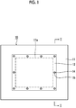
- Fig. 1 is a view when a transparent member-equipped cover of an injection molding machine according to an embodiment is viewed from the inside.
- Fig. 2 is a cross-sectional view taken along line II-II of Fig. 1 .
- An injection molding machine has a transparent member-equipped cover 10.
- the transparent member-equipped cover 10 has a cover 11 and a transparent member 12 which covers an opening portion of the cover 11.
- the cover 11 is a safety door which covers the side of, for example, a mold clamping unit.
- the mold clamping unit performs mold closing, mold clamping, and mold opening of a mold unit.
- the safety door is slidably disposed between a user and the mold clamping unit. If a user opens the safety door, a molding operation of the injection molding machine is temporarily prohibited. On the other hand, if a user shuts the safety door, the prohibition of the molding operation of the injection molding machine is released.
- the transparent member 12 covers an opening portion 11a of the cover 11. A user can visually recognize the inside of the cover 11 through the transparent member 12.
- a resin plate, a glass plate, or the like is used as the transparent member 12.
- the transparent member 12 is mounted on the cover 11 by screwing or the like.
- a male screw 14 is provided at the cover 11, and the male screw 14 penetrates a through-hole 12a of the transparent member 12.
- a female screw 15 is screwed to the tip of the male screw 14, and the female screw 15 presses the transparent member 12 against the cover 11.
- the disposition of the male screw 14 and the female screw 15 may vary.
- a configuration may be made in which a female screw is formed in the cover 11 and a male screw which is screwed to the female screw presses the transparent member 12 against the cover 11.
- the transparent member 12 is mounted on the cover 11 at a plurality of mounting positions.
- the male screw 14 and the female screw 15 are disposed at each mounting position.
- a mounting method is not limited to the screwing.
- the mounting states of the transparent member 12 on the cover 11 at one mounting position and the other mounting position are different from each other.
- the gaps between the cover 11 and the transparent member 12 at one mounting position and the other mounting position are different from each other.
- the gap between the cover 11 and the transparent member 12 is smaller at the central mounting position than at the mounting positions of both ends, and the size of the gap may be zero.
- the transparent member 12 is formed in a flat plate shape in a natural state and mounted on the cover 11 in a state where it has been elastically deformed in a curved plate shape.
- the elastic restoring force of the transparent member 12 acts in a direction causing the transparent member 12 to approach the cover 11, whereas at the central mounting position, the elastic restoring force of the transparent member 12 acts in a direction separating the transparent member 12 from the cover 11. Play disappears due to the elastic restoring force of the transparent member 12, and therefore, shaking of the transparent member 12 can be reduced.
- the rigidity of the transparent member 12 is high, and thus shaking of the transparent member 12 can be further reduced. Further, play disappears or the rigidity becomes higher, whereby in addition to a reduction in the shaking of the transparent member 12, suppression of the deformation of the transparent member 12 due to a difference in thermal expansion between the transparent member 12 and the cover 11 is also possible.
- the transparent member-equipped cover 10 may be provided with a spacer 17 which causes a difference in spacing.
- the spacer 17 secures the gap between the cover 11 and the transparent member 12. It is possible to elastically deform the transparent member 12 into a desired shape.
- the transparent member 12 of this embodiment is formed in a flat plate shape in a natural state.
- the transparent member 12 may be formed in a curved plate shape in a natural state and mounted on the cover 11 as it is.
- the rigidity of the transparent member 12 is higher in the case of the curved plate shape than in the case of the flat plate shape, and therefore, shaking of the transparent member 12 can be reduced.
- suppression of the deformation of the transparent member 12 due to a difference in thermal expansion between the transparent member 12 and the cover 11 is also possible.
- the transparent member-equipped cover 10 of the above-described embodiment is a safety door which covers one face of the mold clamping unit.
- it may be a purge cover or the like which prevents the scattering of a molding material from an injection unit.
- the injection unit fills the inside of the mold unit with a molding material.
- a purge refers to an operation of replacing the molding material of the injection unit.
- the transparent member 12 of the above-described embodiment is curved symmetrically in a vertical direction, as shown in Fig. 2 .
- a direction in which the transparent member 12 is curved may vary.
- the transparent member 12 may be curved symmetrically in a vertical direction, may be curved symmetrically in a horizontal direction, or may be curved point-symmetrically, in Fig. 1 .
- the gaps between the cover 11 and the transparent member 12 at one mounting position and the other mounting position are different from each other.
- the gap between the cover 11 and the transparent member 12 may be the same at all the mounting positions.
- the transparent member 12 may be formed in a curved plate shape in a natural state and mounted on the cover 11 in a state where it has been elastically deformed in a flat plate shape. Play disappears due to the elastic restoring force of the transparent member 12, and therefore, shaking of the transparent member 12 can be reduced. Further, in addition to a reduction in the shaking of the transparent member 12, suppression of the deformation of the transparent member 12 due to a difference in thermal expansion between the transparent member 12 and the cover 11 is also possible. In this case, the directions of action of the elastic restoring force of the transparent member 12 at one mounting position and the other mounting position are different from each other.
Landscapes
- Engineering & Computer Science (AREA)
- Manufacturing & Machinery (AREA)
- Mechanical Engineering (AREA)
- Injection Moulding Of Plastics Or The Like (AREA)
Abstract
Description
- Priority is claimed to
Japanese Patent Application No. 2015-067688, filed March 27, 2015 - The present invention relates to a transparent member-equipped cover of an injection molding machine, and an injection molding machine.
- An injection molding machine has a cover and a transparent member which covers an opening portion of the cover (refer to, for example,
Japanese Unexamined Patent Application Publication No. 2004-261852 - During an operation of the injection molding machine, there is a case where the transparent member shakes.
- The present invention has been made in view of the above problem and has a main object to provide a transparent member-equipped cover of an injection molding machine, in which shaking of a transparent member is reduced.
- In order to solve the above problem, according to an aspect of the present invention, there is provided a transparent member-equipped cover of an injection molding machine including: a cover of the injection molding machine; and a transparent member which covers an opening portion of the cover, wherein the transparent member is mounted on the cover at a plurality of mounting positions, and mounting states of the transparent member on the cover at one mounting position and the other mounting position are different from each other.
- According to the aspect of the present invention, a transparent member-equipped coverofaninjection molding machine, in which shaking of a transparent member is reduced, is provided.
-
-
Fig. 1 is a view when a transparent member-equipped cover of an injection molding machine according to an embodiment is viewed from the inside. -
Fig. 2 is a cross-sectional view taken along line II-II ofFig. 1 . - Hereinafter, an embodiment of the present invention will be described with reference to the drawings. However, in each drawing, identical or corresponding configurations are denoted by identical or corresponding reference numerals and description thereof is omitted.
-
Fig. 1 is a view when a transparent member-equipped cover of an injection molding machine according to an embodiment is viewed from the inside.Fig. 2 is a cross-sectional view taken along line II-II ofFig. 1 . - An injection molding machine has a transparent member-equipped
cover 10. The transparent member-equippedcover 10 has acover 11 and atransparent member 12 which covers an opening portion of thecover 11. - The
cover 11 is a safety door which covers the side of, for example, a mold clamping unit. The mold clamping unit performs mold closing, mold clamping, and mold opening of a mold unit. The safety door is slidably disposed between a user and the mold clamping unit. If a user opens the safety door, a molding operation of the injection molding machine is temporarily prohibited. On the other hand, if a user shuts the safety door, the prohibition of the molding operation of the injection molding machine is released. - The
transparent member 12 covers anopening portion 11a of thecover 11. A user can visually recognize the inside of thecover 11 through thetransparent member 12. As thetransparent member 12, a resin plate, a glass plate, or the like is used. - The
transparent member 12 is mounted on thecover 11 by screwing or the like. For example, amale screw 14 is provided at thecover 11, and themale screw 14 penetrates a through-hole 12a of thetransparent member 12. Afemale screw 15 is screwed to the tip of themale screw 14, and thefemale screw 15 presses thetransparent member 12 against thecover 11. - In addition, the disposition of the
male screw 14 and thefemale screw 15 may vary. For example, a configuration may be made in which a female screw is formed in thecover 11 and a male screw which is screwed to the female screw presses thetransparent member 12 against thecover 11. - The
transparent member 12 is mounted on thecover 11 at a plurality of mounting positions. Themale screw 14 and thefemale screw 15 are disposed at each mounting position. In addition, a mounting method is not limited to the screwing. - Incidentally, in this embodiment, the mounting states of the
transparent member 12 on thecover 11 at one mounting position and the other mounting position are different from each other. For example, the gaps between thecover 11 and thetransparent member 12 at one mounting position and the other mounting position are different from each other. For example, as shown inFig. 2 , the gap between thecover 11 and thetransparent member 12 is smaller at the central mounting position than at the mounting positions of both ends, and the size of the gap may be zero. - In a case where the gaps between the
cover 11 and thetransparent member 12 at one mounting position and the other mounting position are different from each other, for example, thetransparent member 12 is formed in a flat plate shape in a natural state and mounted on thecover 11 in a state where it has been elastically deformed in a curved plate shape. At the mounting positions of both ends, the elastic restoring force of thetransparent member 12 acts in a direction causing thetransparent member 12 to approach thecover 11, whereas at the central mounting position, the elastic restoring force of thetransparent member 12 acts in a direction separating thetransparent member 12 from thecover 11. Play disappears due to the elastic restoring force of thetransparent member 12, and therefore, shaking of thetransparent member 12 can be reduced. Further, compared to the case of the flat plate shape, in the case of the curved plate shape, the rigidity of thetransparent member 12 is high, and thus shaking of thetransparent member 12 can be further reduced. Further, play disappears or the rigidity becomes higher, whereby in addition to a reduction in the shaking of thetransparent member 12, suppression of the deformation of thetransparent member 12 due to a difference in thermal expansion between thetransparent member 12 and thecover 11 is also possible. - In a case where the gaps between the
cover 11 and thetransparent member 12 at one mounting position and the other mounting position are different from each other, the transparent member-equippedcover 10 may be provided with aspacer 17 which causes a difference in spacing. Thespacer 17 secures the gap between thecover 11 and thetransparent member 12. It is possible to elastically deform thetransparent member 12 into a desired shape. - Further, the
transparent member 12 of this embodiment is formed in a flat plate shape in a natural state. However, thetransparent member 12 may be formed in a curved plate shape in a natural state and mounted on thecover 11 as it is. The rigidity of thetransparent member 12 is higher in the case of the curved plate shape than in the case of the flat plate shape, and therefore, shaking of thetransparent member 12 can be reduced. Further, in addition to a reduction in the shaking of thetransparent member 12, suppression of the deformation of thetransparent member 12 due to a difference in thermal expansion between thetransparent member 12 and thecover 11 is also possible. - An embodiment of the transparent member-equipped cover of an injection molding machine has been described above. However, the present invention is not limited to the above-described embodiment, and various modifications and improvements can be made within the scope of the concept of the present invention as stated in the appended claims.
- For example, the transparent member-equipped
cover 10 of the above-described embodiment is a safety door which covers one face of the mold clamping unit. However, it may be a purge cover or the like which prevents the scattering of a molding material from an injection unit. The injection unit fills the inside of the mold unit with a molding material. A purge refers to an operation of replacing the molding material of the injection unit. - The
transparent member 12 of the above-described embodiment is curved symmetrically in a vertical direction, as shown inFig. 2 . However, a direction in which thetransparent member 12 is curved may vary. For example, thetransparent member 12 may be curved symmetrically in a vertical direction, may be curved symmetrically in a horizontal direction, or may be curved point-symmetrically, inFig. 1 . - In the above-described embodiment, the gaps between the
cover 11 and thetransparent member 12 at one mounting position and the other mounting position are different from each other. However, the gap between thecover 11 and thetransparent member 12 may be the same at all the mounting positions. For example, thetransparent member 12 may be formed in a curved plate shape in a natural state and mounted on thecover 11 in a state where it has been elastically deformed in a flat plate shape. Play disappears due to the elastic restoring force of thetransparent member 12, and therefore, shaking of thetransparent member 12 can be reduced. Further, in addition to a reduction in the shaking of thetransparent member 12, suppression of the deformation of thetransparent member 12 due to a difference in thermal expansion between thetransparent member 12 and thecover 11 is also possible. In this case, the directions of action of the elastic restoring force of thetransparent member 12 at one mounting position and the other mounting position are different from each other.
Claims (5)
- A transparent member-equipped cover of an injection molding machine, comprising:a cover (11) of the injection molding machine; anda transparent member (12) which covers an opening portion (11a) of the cover (11),wherein the transparent member (12) is mounted on the cover (11) at a plurality of mounting positions, andmounting states of the transparent member (12) on the cover (11) at one mounting position and the other mounting position are different from each other.
- The transparent member-equipped cover of an injection molding machine according to Claim 1, wherein gaps between the cover (11) and the transparent member (12) at one mounting position and the other mounting position are different from each other.
- The transparent member-equipped cover of an injection molding machine according to Claim 2, further comprising:a spacer (17) which causes a difference in spacing at one mounting position and the other mounting position.
- The transparent member-equipped cover of an injection molding machine according to any one of Claims 1 to 3, wherein directions of action of an elastic restoring force of the transparent member (12) at one mounting position and the other mounting position are different from each other.
- An injection molding machine comprising:a cover (11); anda transparent member (12) which covers an opening portion (11a) of the cover (11),wherein the transparent member (12) is mounted on the cover (11) at a plurality of mounting positions, andmounting states of the transparent member (12) on the cover (11) at one mounting position and the other mounting position are different from each other.
Applications Claiming Priority (1)
| Application Number | Priority Date | Filing Date | Title |
|---|---|---|---|
| JP2015067688A JP6437363B2 (en) | 2015-03-27 | 2015-03-27 | Cover with transparent member of injection molding machine, and injection molding machine |
Publications (2)
| Publication Number | Publication Date |
|---|---|
| EP3072666A1 true EP3072666A1 (en) | 2016-09-28 |
| EP3072666B1 EP3072666B1 (en) | 2018-03-21 |
Family
ID=55696943
Family Applications (1)
| Application Number | Title | Priority Date | Filing Date |
|---|---|---|---|
| EP16162030.7A Active EP3072666B1 (en) | 2015-03-27 | 2016-03-23 | Transparent member-equipped cover of injection molding machine, and injection molding machine |
Country Status (3)
| Country | Link |
|---|---|
| EP (1) | EP3072666B1 (en) |
| JP (1) | JP6437363B2 (en) |
| CN (1) | CN106003571B (en) |
Families Citing this family (1)
| Publication number | Priority date | Publication date | Assignee | Title |
|---|---|---|---|---|
| KR102561179B1 (en) * | 2016-12-30 | 2023-07-31 | 엘에스엠트론 주식회사 | Door Apparatus of Injection Molding Machine |
Citations (1)
| Publication number | Priority date | Publication date | Assignee | Title |
|---|---|---|---|---|
| JP2004261852A (en) | 2003-03-03 | 2004-09-24 | Japan Steel Works Ltd:The | Injection molding machine safety door |
Family Cites Families (1)
| Publication number | Priority date | Publication date | Assignee | Title |
|---|---|---|---|---|
| JP2794314B2 (en) * | 1989-12-28 | 1998-09-03 | 株式会社山城精機製作所 | Door safety device |
-
2015
- 2015-03-27 JP JP2015067688A patent/JP6437363B2/en active Active
-
2016
- 2016-03-23 EP EP16162030.7A patent/EP3072666B1/en active Active
- 2016-03-24 CN CN201610173507.6A patent/CN106003571B/en active Active
Patent Citations (1)
| Publication number | Priority date | Publication date | Assignee | Title |
|---|---|---|---|---|
| JP2004261852A (en) | 2003-03-03 | 2004-09-24 | Japan Steel Works Ltd:The | Injection molding machine safety door |
Also Published As
| Publication number | Publication date |
|---|---|
| JP2016185696A (en) | 2016-10-27 |
| EP3072666B1 (en) | 2018-03-21 |
| JP6437363B2 (en) | 2018-12-12 |
| CN106003571B (en) | 2018-05-29 |
| CN106003571A (en) | 2016-10-12 |
Similar Documents
| Publication | Publication Date | Title |
|---|---|---|
| CN103974566A (en) | Protective case having shock absorption function and applicable to portable electronic devices | |
| EP3096339B1 (en) | Sealing mechanism and key device | |
| EP3133907A1 (en) | Housing | |
| WO2013004991A3 (en) | Casing | |
| CN106949239B (en) | Circuit sealing element and damper | |
| EP3072747A3 (en) | Protector, assembly of wiring module with protector and assembling method therefor | |
| EP2662937A1 (en) | Protector-attached connector | |
| EP3072666B1 (en) | Transparent member-equipped cover of injection molding machine, and injection molding machine | |
| US11934232B2 (en) | Electronic apparatus | |
| JP6623222B2 (en) | Stepped battery | |
| JP6442936B2 (en) | Cover opening / closing structure | |
| USD881136S1 (en) | Tip receptor mount for lightning protection systems | |
| US20180216643A1 (en) | Support member | |
| EP3072667A1 (en) | Transparent member-equipped cover of injection molding machine, and injection molding machine | |
| JP2015034606A (en) | Clip mounting seat for interior or exterior component | |
| CN204927128U (en) | Dust-proof keyboard switches | |
| JP6294683B2 (en) | Inverter device and fan mounting structure | |
| KR20160137795A (en) | Blastwall structure | |
| CN102200164B (en) | Screwing structure | |
| CN104863885B (en) | Slewing | |
| CN106165210A (en) | Protective plate for plug-in connector system | |
| EP3112703B1 (en) | Diaper pin vibration damper | |
| EP2723150A2 (en) | Electronic device | |
| JP2007311594A (en) | Cabinet for accommodating electric apparatus | |
| US20130215590A1 (en) | Cable positioning mechanism and electronic device using the same |
Legal Events
| Date | Code | Title | Description |
|---|---|---|---|
| PUAI | Public reference made under article 153(3) epc to a published international application that has entered the european phase |
Free format text: ORIGINAL CODE: 0009012 |
|
| 17P | Request for examination filed |
Effective date: 20160323 |
|
| AK | Designated contracting states |
Kind code of ref document: A1 Designated state(s): AL AT BE BG CH CY CZ DE DK EE ES FI FR GB GR HR HU IE IS IT LI LT LU LV MC MK MT NL NO PL PT RO RS SE SI SK SM TR |
|
| AX | Request for extension of the european patent |
Extension state: BA ME |
|
| RIC1 | Information provided on ipc code assigned before grant |
Ipc: B29C 45/84 20060101AFI20170830BHEP |
|
| GRAP | Despatch of communication of intention to grant a patent |
Free format text: ORIGINAL CODE: EPIDOSNIGR1 |
|
| INTG | Intention to grant announced |
Effective date: 20171013 |
|
| GRAS | Grant fee paid |
Free format text: ORIGINAL CODE: EPIDOSNIGR3 |
|
| GRAA | (expected) grant |
Free format text: ORIGINAL CODE: 0009210 |
|
| AK | Designated contracting states |
Kind code of ref document: B1 Designated state(s): AL AT BE BG CH CY CZ DE DK EE ES FI FR GB GR HR HU IE IS IT LI LT LU LV MC MK MT NL NO PL PT RO RS SE SI SK SM TR |
|
| REG | Reference to a national code |
Ref country code: GB Ref legal event code: FG4D |
|
| REG | Reference to a national code |
Ref country code: CH Ref legal event code: EP |
|
| REG | Reference to a national code |
Ref country code: AT Ref legal event code: REF Ref document number: 980618 Country of ref document: AT Kind code of ref document: T Effective date: 20180415 |
|
| REG | Reference to a national code |
Ref country code: IE Ref legal event code: FG4D |
|
| REG | Reference to a national code |
Ref country code: DE Ref legal event code: R096 Ref document number: 602016002068 Country of ref document: DE |
|
| REG | Reference to a national code |
Ref country code: CH Ref legal event code: NV Representative=s name: SCHNEIDER FELDMANN AG PATENT- UND MARKENANWAEL, CH |
|
| REG | Reference to a national code |
Ref country code: NL Ref legal event code: MP Effective date: 20180321 |
|
| PG25 | Lapsed in a contracting state [announced via postgrant information from national office to epo] |
Ref country code: CY Free format text: LAPSE BECAUSE OF FAILURE TO SUBMIT A TRANSLATION OF THE DESCRIPTION OR TO PAY THE FEE WITHIN THE PRESCRIBED TIME-LIMIT Effective date: 20180321 Ref country code: NO Free format text: LAPSE BECAUSE OF FAILURE TO SUBMIT A TRANSLATION OF THE DESCRIPTION OR TO PAY THE FEE WITHIN THE PRESCRIBED TIME-LIMIT Effective date: 20180621 Ref country code: FI Free format text: LAPSE BECAUSE OF FAILURE TO SUBMIT A TRANSLATION OF THE DESCRIPTION OR TO PAY THE FEE WITHIN THE PRESCRIBED TIME-LIMIT Effective date: 20180321 Ref country code: LT Free format text: LAPSE BECAUSE OF FAILURE TO SUBMIT A TRANSLATION OF THE DESCRIPTION OR TO PAY THE FEE WITHIN THE PRESCRIBED TIME-LIMIT Effective date: 20180321 Ref country code: HR Free format text: LAPSE BECAUSE OF FAILURE TO SUBMIT A TRANSLATION OF THE DESCRIPTION OR TO PAY THE FEE WITHIN THE PRESCRIBED TIME-LIMIT Effective date: 20180321 |
|
| REG | Reference to a national code |
Ref country code: LT Ref legal event code: MG4D |
|
| PG25 | Lapsed in a contracting state [announced via postgrant information from national office to epo] |
Ref country code: BG Free format text: LAPSE BECAUSE OF FAILURE TO SUBMIT A TRANSLATION OF THE DESCRIPTION OR TO PAY THE FEE WITHIN THE PRESCRIBED TIME-LIMIT Effective date: 20180621 Ref country code: RS Free format text: LAPSE BECAUSE OF FAILURE TO SUBMIT A TRANSLATION OF THE DESCRIPTION OR TO PAY THE FEE WITHIN THE PRESCRIBED TIME-LIMIT Effective date: 20180321 Ref country code: LV Free format text: LAPSE BECAUSE OF FAILURE TO SUBMIT A TRANSLATION OF THE DESCRIPTION OR TO PAY THE FEE WITHIN THE PRESCRIBED TIME-LIMIT Effective date: 20180321 Ref country code: SE Free format text: LAPSE BECAUSE OF FAILURE TO SUBMIT A TRANSLATION OF THE DESCRIPTION OR TO PAY THE FEE WITHIN THE PRESCRIBED TIME-LIMIT Effective date: 20180321 Ref country code: GR Free format text: LAPSE BECAUSE OF FAILURE TO SUBMIT A TRANSLATION OF THE DESCRIPTION OR TO PAY THE FEE WITHIN THE PRESCRIBED TIME-LIMIT Effective date: 20180622 |
|
| PG25 | Lapsed in a contracting state [announced via postgrant information from national office to epo] |
Ref country code: IT Free format text: LAPSE BECAUSE OF FAILURE TO SUBMIT A TRANSLATION OF THE DESCRIPTION OR TO PAY THE FEE WITHIN THE PRESCRIBED TIME-LIMIT Effective date: 20180321 Ref country code: RO Free format text: LAPSE BECAUSE OF FAILURE TO SUBMIT A TRANSLATION OF THE DESCRIPTION OR TO PAY THE FEE WITHIN THE PRESCRIBED TIME-LIMIT Effective date: 20180321 Ref country code: PL Free format text: LAPSE BECAUSE OF FAILURE TO SUBMIT A TRANSLATION OF THE DESCRIPTION OR TO PAY THE FEE WITHIN THE PRESCRIBED TIME-LIMIT Effective date: 20180321 Ref country code: ES Free format text: LAPSE BECAUSE OF FAILURE TO SUBMIT A TRANSLATION OF THE DESCRIPTION OR TO PAY THE FEE WITHIN THE PRESCRIBED TIME-LIMIT Effective date: 20180321 Ref country code: NL Free format text: LAPSE BECAUSE OF FAILURE TO SUBMIT A TRANSLATION OF THE DESCRIPTION OR TO PAY THE FEE WITHIN THE PRESCRIBED TIME-LIMIT Effective date: 20180321 Ref country code: EE Free format text: LAPSE BECAUSE OF FAILURE TO SUBMIT A TRANSLATION OF THE DESCRIPTION OR TO PAY THE FEE WITHIN THE PRESCRIBED TIME-LIMIT Effective date: 20180321 Ref country code: AL Free format text: LAPSE BECAUSE OF FAILURE TO SUBMIT A TRANSLATION OF THE DESCRIPTION OR TO PAY THE FEE WITHIN THE PRESCRIBED TIME-LIMIT Effective date: 20180321 |
|
| PG25 | Lapsed in a contracting state [announced via postgrant information from national office to epo] |
Ref country code: SM Free format text: LAPSE BECAUSE OF FAILURE TO SUBMIT A TRANSLATION OF THE DESCRIPTION OR TO PAY THE FEE WITHIN THE PRESCRIBED TIME-LIMIT Effective date: 20180321 Ref country code: CZ Free format text: LAPSE BECAUSE OF FAILURE TO SUBMIT A TRANSLATION OF THE DESCRIPTION OR TO PAY THE FEE WITHIN THE PRESCRIBED TIME-LIMIT Effective date: 20180321 Ref country code: SK Free format text: LAPSE BECAUSE OF FAILURE TO SUBMIT A TRANSLATION OF THE DESCRIPTION OR TO PAY THE FEE WITHIN THE PRESCRIBED TIME-LIMIT Effective date: 20180321 |
|
| REG | Reference to a national code |
Ref country code: BE Ref legal event code: MM Effective date: 20180331 |
|
| REG | Reference to a national code |
Ref country code: IE Ref legal event code: MM4A |
|
| PG25 | Lapsed in a contracting state [announced via postgrant information from national office to epo] |
Ref country code: PT Free format text: LAPSE BECAUSE OF FAILURE TO SUBMIT A TRANSLATION OF THE DESCRIPTION OR TO PAY THE FEE WITHIN THE PRESCRIBED TIME-LIMIT Effective date: 20180723 Ref country code: LU Free format text: LAPSE BECAUSE OF NON-PAYMENT OF DUE FEES Effective date: 20180323 |
|
| REG | Reference to a national code |
Ref country code: DE Ref legal event code: R097 Ref document number: 602016002068 Country of ref document: DE |
|
| PLBE | No opposition filed within time limit |
Free format text: ORIGINAL CODE: 0009261 |
|
| STAA | Information on the status of an ep patent application or granted ep patent |
Free format text: STATUS: NO OPPOSITION FILED WITHIN TIME LIMIT |
|
| PG25 | Lapsed in a contracting state [announced via postgrant information from national office to epo] |
Ref country code: DK Free format text: LAPSE BECAUSE OF FAILURE TO SUBMIT A TRANSLATION OF THE DESCRIPTION OR TO PAY THE FEE WITHIN THE PRESCRIBED TIME-LIMIT Effective date: 20180321 Ref country code: MC Free format text: LAPSE BECAUSE OF FAILURE TO SUBMIT A TRANSLATION OF THE DESCRIPTION OR TO PAY THE FEE WITHIN THE PRESCRIBED TIME-LIMIT Effective date: 20180321 Ref country code: IE Free format text: LAPSE BECAUSE OF NON-PAYMENT OF DUE FEES Effective date: 20180323 |
|
| 26N | No opposition filed |
Effective date: 20190102 |
|
| PG25 | Lapsed in a contracting state [announced via postgrant information from national office to epo] |
Ref country code: BE Free format text: LAPSE BECAUSE OF NON-PAYMENT OF DUE FEES Effective date: 20180331 |
|
| PG25 | Lapsed in a contracting state [announced via postgrant information from national office to epo] |
Ref country code: FR Free format text: LAPSE BECAUSE OF NON-PAYMENT OF DUE FEES Effective date: 20180521 |
|
| PG25 | Lapsed in a contracting state [announced via postgrant information from national office to epo] |
Ref country code: SI Free format text: LAPSE BECAUSE OF FAILURE TO SUBMIT A TRANSLATION OF THE DESCRIPTION OR TO PAY THE FEE WITHIN THE PRESCRIBED TIME-LIMIT Effective date: 20180321 |
|
| PG25 | Lapsed in a contracting state [announced via postgrant information from national office to epo] |
Ref country code: MT Free format text: LAPSE BECAUSE OF NON-PAYMENT OF DUE FEES Effective date: 20180323 |
|
| PG25 | Lapsed in a contracting state [announced via postgrant information from national office to epo] |
Ref country code: TR Free format text: LAPSE BECAUSE OF FAILURE TO SUBMIT A TRANSLATION OF THE DESCRIPTION OR TO PAY THE FEE WITHIN THE PRESCRIBED TIME-LIMIT Effective date: 20180321 |
|
| PG25 | Lapsed in a contracting state [announced via postgrant information from national office to epo] |
Ref country code: MK Free format text: LAPSE BECAUSE OF NON-PAYMENT OF DUE FEES Effective date: 20180321 Ref country code: HU Free format text: LAPSE BECAUSE OF FAILURE TO SUBMIT A TRANSLATION OF THE DESCRIPTION OR TO PAY THE FEE WITHIN THE PRESCRIBED TIME-LIMIT; INVALID AB INITIO Effective date: 20160323 |
|
| REG | Reference to a national code |
Ref country code: AT Ref legal event code: UEP Ref document number: 980618 Country of ref document: AT Kind code of ref document: T Effective date: 20180321 |
|
| PG25 | Lapsed in a contracting state [announced via postgrant information from national office to epo] |
Ref country code: IS Free format text: LAPSE BECAUSE OF FAILURE TO SUBMIT A TRANSLATION OF THE DESCRIPTION OR TO PAY THE FEE WITHIN THE PRESCRIBED TIME-LIMIT Effective date: 20180721 |
|
| REG | Reference to a national code |
Ref country code: CH Ref legal event code: PFA Owner name: SUMITOMO HEAVY INDUSTRIES, LTD., JP Free format text: FORMER OWNER: SUMITOMO HEAVY INDUSTRIES, LTD., JP |
|
| GBPC | Gb: european patent ceased through non-payment of renewal fee |
Effective date: 20200323 |
|
| PG25 | Lapsed in a contracting state [announced via postgrant information from national office to epo] |
Ref country code: GB Free format text: LAPSE BECAUSE OF NON-PAYMENT OF DUE FEES Effective date: 20200323 |
|
| PGFP | Annual fee paid to national office [announced via postgrant information from national office to epo] |
Ref country code: CH Payment date: 20220215 Year of fee payment: 7 Ref country code: AT Payment date: 20220225 Year of fee payment: 7 |
|
| REG | Reference to a national code |
Ref country code: CH Ref legal event code: PL |
|
| REG | Reference to a national code |
Ref country code: AT Ref legal event code: MM01 Ref document number: 980618 Country of ref document: AT Kind code of ref document: T Effective date: 20230323 |
|
| PG25 | Lapsed in a contracting state [announced via postgrant information from national office to epo] |
Ref country code: LI Free format text: LAPSE BECAUSE OF NON-PAYMENT OF DUE FEES Effective date: 20230331 Ref country code: CH Free format text: LAPSE BECAUSE OF NON-PAYMENT OF DUE FEES Effective date: 20230331 Ref country code: AT Free format text: LAPSE BECAUSE OF NON-PAYMENT OF DUE FEES Effective date: 20230323 |
|
| PGFP | Annual fee paid to national office [announced via postgrant information from national office to epo] |
Ref country code: DE Payment date: 20260128 Year of fee payment: 11 |