EP3072476A1 - Intraocular lens insertion instrument - Google Patents
Intraocular lens insertion instrument Download PDFInfo
- Publication number
- EP3072476A1 EP3072476A1 EP14864525.2A EP14864525A EP3072476A1 EP 3072476 A1 EP3072476 A1 EP 3072476A1 EP 14864525 A EP14864525 A EP 14864525A EP 3072476 A1 EP3072476 A1 EP 3072476A1
- Authority
- EP
- European Patent Office
- Prior art keywords
- intraocular lens
- needle
- guide wall
- hole
- syringe
- Prior art date
- Legal status (The legal status is an assumption and is not a legal conclusion. Google has not performed a legal analysis and makes no representation as to the accuracy of the status listed.)
- Granted
Links
- 238000003780 insertion Methods 0.000 title claims abstract description 107
- 230000037431 insertion Effects 0.000 title claims abstract description 107
- 239000000314 lubricant Substances 0.000 claims abstract description 17
- 210000005252 bulbus oculi Anatomy 0.000 claims abstract description 16
- 210000000695 crystalline len Anatomy 0.000 description 138
- 238000010586 diagram Methods 0.000 description 46
- 238000012986 modification Methods 0.000 description 37
- 230000004048 modification Effects 0.000 description 37
- KIUKXJAPPMFGSW-DNGZLQJQSA-N (2S,3S,4S,5R,6R)-6-[(2S,3R,4R,5S,6R)-3-Acetamido-2-[(2S,3S,4R,5R,6R)-6-[(2R,3R,4R,5S,6R)-3-acetamido-2,5-dihydroxy-6-(hydroxymethyl)oxan-4-yl]oxy-2-carboxy-4,5-dihydroxyoxan-3-yl]oxy-5-hydroxy-6-(hydroxymethyl)oxan-4-yl]oxy-3,4,5-trihydroxyoxane-2-carboxylic acid Chemical compound CC(=O)N[C@H]1[C@H](O)O[C@H](CO)[C@@H](O)[C@@H]1O[C@H]1[C@H](O)[C@@H](O)[C@H](O[C@H]2[C@@H]([C@@H](O[C@H]3[C@@H]([C@@H](O)[C@H](O)[C@H](O3)C(O)=O)O)[C@H](O)[C@@H](CO)O2)NC(C)=O)[C@@H](C(O)=O)O1 KIUKXJAPPMFGSW-DNGZLQJQSA-N 0.000 description 6
- 229920002674 hyaluronan Polymers 0.000 description 6
- 229960003160 hyaluronic acid Drugs 0.000 description 6
- 230000003287 optical effect Effects 0.000 description 5
- 239000003190 viscoelastic substance Substances 0.000 description 4
- 239000004743 Polypropylene Substances 0.000 description 3
- 230000000694 effects Effects 0.000 description 3
- 238000000034 method Methods 0.000 description 3
- 230000002093 peripheral effect Effects 0.000 description 3
- -1 polypropylene Polymers 0.000 description 3
- 229920001155 polypropylene Polymers 0.000 description 3
- 208000002177 Cataract Diseases 0.000 description 2
- 210000001508 eye Anatomy 0.000 description 2
- 238000001746 injection moulding Methods 0.000 description 2
- 239000000463 material Substances 0.000 description 2
- 239000011347 resin Substances 0.000 description 2
- 229920005989 resin Polymers 0.000 description 2
- 238000011282 treatment Methods 0.000 description 2
- 208000035473 Communicable disease Diseases 0.000 description 1
- 201000009310 astigmatism Diseases 0.000 description 1
- 238000005452 bending Methods 0.000 description 1
- 210000004087 cornea Anatomy 0.000 description 1
- 230000002708 enhancing effect Effects 0.000 description 1
- 230000005484 gravity Effects 0.000 description 1
- 230000012447 hatching Effects 0.000 description 1
- 208000015181 infectious disease Diseases 0.000 description 1
- 230000010365 information processing Effects 0.000 description 1
- 238000002347 injection Methods 0.000 description 1
- 239000007924 injection Substances 0.000 description 1
- 238000004519 manufacturing process Methods 0.000 description 1
- 238000000465 moulding Methods 0.000 description 1
- 230000036316 preload Effects 0.000 description 1
- 239000002994 raw material Substances 0.000 description 1
- 230000003014 reinforcing effect Effects 0.000 description 1
- 239000000243 solution Substances 0.000 description 1
- 230000000087 stabilizing effect Effects 0.000 description 1
- 239000000126 substance Substances 0.000 description 1
- 238000001356 surgical procedure Methods 0.000 description 1
Images


Classifications
-
- A—HUMAN NECESSITIES
- A61—MEDICAL OR VETERINARY SCIENCE; HYGIENE
- A61F—FILTERS IMPLANTABLE INTO BLOOD VESSELS; PROSTHESES; DEVICES PROVIDING PATENCY TO, OR PREVENTING COLLAPSING OF, TUBULAR STRUCTURES OF THE BODY, e.g. STENTS; ORTHOPAEDIC, NURSING OR CONTRACEPTIVE DEVICES; FOMENTATION; TREATMENT OR PROTECTION OF EYES OR EARS; BANDAGES, DRESSINGS OR ABSORBENT PADS; FIRST-AID KITS
- A61F2/00—Filters implantable into blood vessels; Prostheses, i.e. artificial substitutes or replacements for parts of the body; Appliances for connecting them with the body; Devices providing patency to, or preventing collapsing of, tubular structures of the body, e.g. stents
- A61F2/02—Prostheses implantable into the body
- A61F2/14—Eye parts, e.g. lenses, corneal implants; Implanting instruments specially adapted therefor; Artificial eyes
- A61F2/16—Intraocular lenses
- A61F2/1662—Instruments for inserting intraocular lenses into the eye
- A61F2/1675—Instruments for inserting intraocular lenses into the eye with a lubricated inner surface, e.g. the lubricant being coated on the inner surface or being injected through a port
-
- A—HUMAN NECESSITIES
- A61—MEDICAL OR VETERINARY SCIENCE; HYGIENE
- A61F—FILTERS IMPLANTABLE INTO BLOOD VESSELS; PROSTHESES; DEVICES PROVIDING PATENCY TO, OR PREVENTING COLLAPSING OF, TUBULAR STRUCTURES OF THE BODY, e.g. STENTS; ORTHOPAEDIC, NURSING OR CONTRACEPTIVE DEVICES; FOMENTATION; TREATMENT OR PROTECTION OF EYES OR EARS; BANDAGES, DRESSINGS OR ABSORBENT PADS; FIRST-AID KITS
- A61F2/00—Filters implantable into blood vessels; Prostheses, i.e. artificial substitutes or replacements for parts of the body; Appliances for connecting them with the body; Devices providing patency to, or preventing collapsing of, tubular structures of the body, e.g. stents
- A61F2/02—Prostheses implantable into the body
- A61F2/14—Eye parts, e.g. lenses, corneal implants; Implanting instruments specially adapted therefor; Artificial eyes
- A61F2/16—Intraocular lenses
- A61F2/1662—Instruments for inserting intraocular lenses into the eye
- A61F2/1678—Instruments for inserting intraocular lenses into the eye with a separate cartridge or other lens setting part for storage of a lens, e.g. preloadable for shipping
Definitions
- the embodiments discussed herein pertain to an intraocular lens insertion apparatus.
- Intraocular lenses are widely used to be replaced with human opacity crystalline lenses in cataract treatments or normal human crystalline lenses for compensating the optical powers of the lenses.
- intraocular lens insertion surgeries for the cataract treatments a discission wound (cut) which is several millimeters in length is produced at the edge of the cornea, the human crystalline lens is crushed and removed by phacoemulsification and aspiration etc. and the intraocular lens is inserted and fixed in the eye, for example.
- a so-called preload (or preset) type insertion apparatus where the intraocular lens is placed in an accommodating member in advance.
- a user inserts a distal end opening of an inserting sleeve member formed on a distal end member of an apparatus body into the inside of an eyeball through the above-mentioned incision, and also in a state where the intraocular lens is deformed into a compact shape in the inside of the apparatus body, the intraocular lens is pushed out by a rod-like plunger through the distal end opening of the inserting sleeve member so that the intraocular lens is released and inserted into the inside of the eyeball.
- an intraocular lens can be easily inserted into an eyeball by making use of an incision which is formed for taking out and removing a crystalline lens. Accordingly, an operation can be simplified and, at the same time, the occurrence of astigmatism and the occurrence of an infectious disease after the operation can be suppressed.
- a needle of a syringe is inserted into the inside of the insertion apparatus through a hole formed in the insertion apparatus, and the viscoelastic material is injected into particularly a place where the intraocular lens is accommodated in the inside of the insertion apparatus by the syringe.
- the hole through which the needle of the syringe is inserted is barely visible and hence, it is often the case that whether or not the needle of the syringe can be skillfully advanced into the inside of the insertion apparatus through the hole depends on experience and sense of touch of a user.
- the technique of this disclosure has been made in view of the above-mentioned circumstances, and it is an obj ect of this disclosure to realize an insertion apparatus which supports the injection of a lubricant into an accommodating member for an intraocular lens.
- an intraocular lens insertion apparatus including an accommodating member integrally or independently formed on an apparatus body which is inserted into an eyeball, allowing arrangement of the intraocular lens in the apparatus body by accommodating the intraocular lens therein, and having a hole through which a needle of a syringe which supplies a lubricant to the intraocular lens passes; and a guide wall member formed on the accommodating member at a position adjacent to the hole, and being configured to guide the needle of the syringe to the hole.
- the guide wall member is configured so as to prevent the needle of the syringe from coming into contact with a lens body of the intraocular lens accommodated in the accommodating member in a state where the needle of the syringe which is made to pass through the hole is brought into contact with the guide wall.
- the guide wall member is configured to surround the hole.
- a distance from the center of the hole to a predetermined portion of an inner wall of the guide wall member may be set shorter than a distance from the center of the hole to the other portion of the inner wall of the guide wall member.
- the guide wall member has an opening member which allows movement of the needle of the syringe within a range where the needle of the syringe which is made to pass through the hole is not brought into contact with a lens body of the intraocular lens accommodated in the accommodating member.
- An inclined member which connects an inner wall of the guide wall member and the hole may be formed on the guide wall member.
- a stepped member may be formed on the guide wall member by setting a height of an inner wall side of the guide wall member in a thickness direction lower than a height of an outer wall of the guide wall member.
- the hole is formed on a distal end side of the apparatus body with respect to the intraocular lens accommodated in the accommodating member.
- an intraocular lens insertion apparatus may include: an accommodating member integrally or independently formed on an apparatus body which is inserted into an eyeball, allowing arrangement of the intraocular lens in the apparatus body by accommodating the intraocular lens therein, and having a hole through which a needle of a syringe which supplies a lubricant to the intraocular lens passes; and a guide wall member formed on the accommodating member at a position adjacent to the hole, and being configured to guide the needle of the syringe to the hole, wherein the intraocular lens is accommodated in the accommodating member before the insertion apparatus is placed on a market.
- FIG. 1 is a perspective diagram illustrating a whole intraocular lens insertion apparatus 1 of the present embodiment (hereinafter, also simply referred to as an insertion apparatus 1).
- the insertion apparatus 1 includes a nozzle body 10 which forms an apparatus body, a plunger 30 which forms a push member for pushing an intraocular lens, and a stage member 12 and a stage lid member 13 which form an accommodating member for accommodating an intraocular lens.
- the stage member 12 is integrally or independently formed on the nozzle body 10.
- the plunger 30 is inserted into the nozzle body 10.
- An intraocular lens 2 is set in the stage member 12.
- the stage member 12 is integrally formed with the stage lid member 13.
- FIG. 1 illustrates a state where the stage lid member 13 is opened. Further, FIG.
- FIG. 1 illustrates an upper surface of the stage lid member 13.
- An insertion member 20 for a needle of a syringe filled with a lubricant for the intraocular lens is formed on the stage lid member 13.
- Setting surface through-holes 12c for assembling a positioning member 50 for positioning the intraocular lens 2 are formed in the nozzle body 10. The detailed configuration of the positioning member 50 is described later.
- FIG. 1 is a perspective diagram when the intraocular lens insertion apparatus 1 is viewed from below. Accordingly, the insertion member 20 is configured to project toward the outside of the stage lid member 13 when the stage lid member 13 is closed.
- FIG. 2 illustrates an enlarged diagram of the insertion member 20 for a needle of a syringe inserted.
- the insertion member 20 has: a needle hole 20a which is a hole into which a needle of a syringe is inserted; and a guide wall member 20b which guides a distal end of the needle of the syringe into the needle hole 20a.
- the guide wall member 20b also has a function of restricting the movement, the inclination, the rotation and the like of a needle of a syringe after the needle is inserted into the needle hole 20a.
- an inclined member 20c which extends downward toward the needle hole 20a is formed on the stage lid member 13 at a region surrounded by the guide wall member 20b.
- the intraocular lens 2 is placed and positioned on the stage member 12.
- the stage lid member 13 is closed by rotating the stage lid member 13 about a connecting member 14 between the stage lid member 13 and the stage member 12.
- the plunger 30 is pushed into a nozzle body 10 side, the plunger 30 is brought into contact with the intraocular lens 2 placed on the stage member 12.
- the intraocular lens 2 is moved to a distal end member 10a of the nozzle body 10 from the stage member 12 through a nozzle member 15 connected with the stage member 12. Then, the intraocular lens 2 is pushed out through an opening of the distal end member 10a.
- FIG. 3A and FIG. 3B illustrate the schematic configuration of the insertion apparatus 1 of the present embodiment.
- FIG. 3A is a plan diagram of the insertion apparatus 1 when the stage lid member 13 is opened
- FIG. 3B is a side diagram of the insertion apparatus 1 when the stage lid member 13 is closed.
- the nozzle body 10 of the insertion apparatus 1 is formed as a tube with an approximately rectangular cross section, an end member of the nozzle body 10 on one side is largely opened (hereinafter, the largely-opened side is referred to as a rear end member 10b), and a nozzle member 15 which forms a tapered insertion cylindrical member and the distal end member 10a are formed on an end member of the nozzle body 10 on the other side.
- the distal endmember 10a has an obliquely formed opening.
- the plunger 30 is inserted into the nozzle body 10 and is movable in an extensible and retractable manner.
- the direction extending toward the distal end member 10a from the rear end member 10b of the nozzle body 10 is assumed as the frontward direction
- the direction opposite to the frontward direction is assumed as the rearward direction
- the direction toward a viewer's side with respect to a paper surface on which FIG. 3A is drawn is assumed as the upward direction
- the direction opposite to the upward direction is assumed as the downward direction
- the direction toward a viewer's side with respect to a paper surface on which FIG. 3B is drawn is assumed as the leftward direction
- the direction opposite to the leftward direction is assumed as the rightward direction.
- an upper side corresponds to a front side along an optical axis of a lens body 2a described later
- a lower side corresponds to a rear side along the optical axis of the lens body 2a
- a front side corresponds to a front side in the pushing direction of the plunger 30
- a rear side corresponds to a rear side in the pushing direction of the plunger 30.
- a hold member 11 which projects in a plate shape and on which a user hooks his fingers when he pushes the plunger 30 toward the distal end side of the nozzle body 10 is integrally formed on the nozzle body 10 in the vicinity of the rear end member 10b of the nozzle body 10.
- the stage member 12 on which the intraocular lens 2 is to be set is formed on a member of the nozzle body 10 behind the nozzle member 15.
- the stage member 12 is configured such that an upper side of the nozzle body 10 is opened by opening the stage lid member 13.
- the positioning member 50 is mounted on the stage member 12 from below the nozzle body 10. With the use of the positioning member 50, the intraocular lens 2 is stably held in the stage member 12 even before the insertion apparatus 1 is used (during transportation).
- the intraocular lens 2 is set on the stage member 12 such that a front side along an optical axis is directed upward in a state where the stage lid member 13 is opened and the positioning member 50 is mounted on the stage member 12. Then, the insertion apparatus 1 is shipped after the stage lid member 13 is closed, and the insertion apparatus 1 is sold. Then, at the time of using the insertion apparatus 1, a user inserts a needle of a syringe filled with a lubricant for an intraocular lens into the inside of the stage member 12 through the needle hole 20a of the insertion member 20 and injects the lubricant.
- the user removes the positioning member 50 while holding the stage lid member 13 in a closed state and, thereafter, pushes the plunger 30 toward the distal end side of the nozzle body 10. Due to such an operation, the intraocular lens 2 is pushed by the plunger 30 so as to move the intraocular lens 2 to the nozzle member 15, and the intraocular lens 2 is released into the inside of an eyeball from the distal end member 10a.
- the nozzle body 10, the plunger 30, and the positioning member 50 are formed using a resin such as polypropylene.
- Polypropylene has been proven as a material used for medical apparatuses. In addition, polypropylene is reliable in chemical resistance etc.
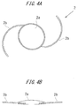
- FIG. 4A and FIG. 4B are diagrams illustrating the schematic configuration of the intraocular lens 2.
- FIG. 4A is a plan diagram
- FIG. 4B is a side diagram.
- the intraocular lens 2 is a so-called three-piece type intraocular lens.
- the intraocular lens 2 is formed of the lens body 2a having a predetermined refractivity, and two whisker-like support members 2b, 2b which are connected to the lens body 2a and are provided for holding the lens body 2a in the inside of an eyeball. Both the lens body 2a and the support members 2b are formed using a flexible resin material.
- the present invention is also applicable to an insertion apparatus for inserting a so-called one-piece-type intraocular lens where a support member and an optical member are formed into one member by molding.
- the intraocular lens 2 is set such that one of two support members 2b, 2b is arranged on a rear side of the lens body 2a, and the other of two support members 2b, 2b is arranged on a front side of the lens body 2a.
- FIG. 5 is a plan diagram of the nozzle body 10.
- the intraocular lens 2 is set on the stage member 12. In such a state, the intraocular lens 2 is pushed by the plunger 30, and is released from the distal end member 10a.
- a through-hole 10c whose cross-sectional shape changes corresponding to a change in a profile of the nozzle body 10 is formed in the inside of the nozzle body 10.
- the intraocular lens 2 is deformed corresponding to a change in a cross-sectional shape of the through-hole 10c formed in the inside of the nozzle body 10, and is released after being deformed into a shape which facilitates the entrance of the intraocular lens 2 into the incision formed in an eyeball of a patient.
- the distal end member 10a has an obliquely cut shape such that an upper region of the nozzle member 15 extends more toward a front side than a lower region of the nozzle member 15.
- the obliquely cut shape of the distal end member 10a may be formed by obliquely cutting the distal end member 10a so as to have a straight line shape as viewed from a lateral direction or may be formed by obliquely cutting the distal end member 10a so as to have an outwardly bulging shape or a curved surface shape.
- a stage groove 12a having a width slightly larger than a diameter of the lens body 2a of the intraocular lens 2 is formed on the stage member 12.
- a size of the stage groove 12a in the longitudinal direction is set larger than a total size of the intraocular lens 2 including the support members 2b, 2b extending from both sides of the intraocular lens 2.
- a setting surface 12b is formed of a bottom surface of the stage groove 12a. The position of the setting surface 12b in a vertical direction is set higher than the height position of a bottom surface of the through-hole 10c formed in the nozzle body 10, and the setting surface 12b and the bottom surface of the through-hole 10c are connected to each other by a bottom member inclined surface 10d.
- the stage member 12 and the stage lid member 13 are integrally formed with each other.
- a size of the stage lid member 13 in the longitudinal direction is set substantially equal to a size of the stage member 12 in the longitudinal direction.
- the stage lid member 13 is connected to the stage member 12 by a thin-plate-like connecting member 14 which is formed in an extending manner toward the stage lid member 13 side from a side surface of the stage member 12.
- the connecting member 14 is formed in a bendable manner at a center portion thereof, and the stage lid member 13 overlaps with the stage member 12 from above by bending the connecting member 14 so that the stage lid member 13 is closed.
- stage lid member 13 ribs 13a and a rib 13b for reinforcing the stage lid member 13 and for stabilizing the position of the intraocular lens 2 are formed on a surface of the stage lid member 13 which faces the setting surface 12b in an opposed manner in a lid closed state.
- Guide projections 13c are formed on the stage lid member 13 as an upper guide for the plunger 30.
- the needle hole 20a is formed in the stage lid member 13 as an insertion hole for injecting a hyaluronic acid into the stage member 12 using a syringe before an operation of inserting the intraocular lens 2 into the inside of an eyeball is performed.
- the needle hole 20a is a hole which connects the outside of the stage member 12 and the intraocular lens 2 accommodated in the stage member 12 to each other when the stage lid member 13 is closed. A user inserts a needle of a syringe through the needle hole 20a before the insertion operation of the intraocular lens 2 is performed, and supplies a hyaluronic acid to the necessary position in the inside of the stage member 12.
- the positioning member 50 is detachably mounted on a lower side of the setting surface 12b of the stage member 12.
- FIG. 6A and FIG. 6B illustrate schematic configuration of the positioning member 50.
- FIG. 6A is a plan diagram of the positioning member 50
- FIG. 6B is a left side diagram of the positioning member 50.
- the positioning member 50 is formed as a body separate from the nozzle body 10, and is configured such that a pair of side wall members 51, 51 is connected to each other by a connecting member 52.
- Holding members 53, 53 which extend and expand outwardly are formed on lower ends of the side wall members 51 respectively.
- a pair of first placing members 54, 54 which has an arcuate shape as viewed from above and projects upward is formed on upper end members of the respective side wall members 51, 51.
- First positioning members 55, 55 are formed on outer peripheral sides of upper end surfaces of the first placing members 54, 54 in a projecting manner.
- a distance between inner arcuate peripheral sides of the first positioning members 55, 55 is set slightly larger than a diameter size of the lens body 2a of the intraocular lens 2.
- a pair of second placing members 56, 56 which has a rectangular shape as viewed from above and projects upward is formed on both ends of the connecting member 52 in a longitudinal direction.
- a height of upper surfaces of the second placing members 56, 56 is set substantially equal to a height of the upper surfaces of the first placing members 54, 54.
- Second positioning members 57, 57 which project further upward are formed on outer portions of the upper surfaces of the second placing members 56, 56 such that the second positioning members 57, 57 extend over the whole regions of the second placing members 56, 56 in the lateral direction.
- a distance between inner sides of the second positioning members 57, 57 is set slightly larger than the diameter size of the lens body 2a of the intraocular lens 2.
- engaging pawls 58, 58 which project slightly in the longitudinal direction respectively are formed on upper end members of the second placing members 56, 56 respectively over the whole region of the upper end members in the lateral direction.
- the above-mentioned positioning member 50 is assembled to the nozzle body 10 from below the setting surface 12b of the nozzle body 10.
- the setting surface through-holes 12c which penetrate the setting surface 12b in a thickness direction are formed in the setting surface 12b of the nozzle body 10.
- Profiles of the setting surface through-holes 12c have a shape slightly larger than and substantially similar to a shape of the first placing members 54, 54 and a shape of the second placing members 56, 56 of the positioning member 50 as viewed from above.
- the engaging pawls 58, 58 respectively formed on the second positioning members 57, 57 project from the setting surface 12b through the setting surface through-holes 12c, and are engaged with the upper surface of the setting surface 12b.
- the positioning member 50 is assembled to the nozzle body 10 from below, and the first placing members 54, 54 and the second placing members 56, 56 are fixed to the setting surface 12b in a state where the first placing members 54, 54 and the second placing members 56, 56 project from the setting surface 12b.
- a bottom surface of an outer peripheral portion of the lens body 2a is placed on the upper surfaces of the first placing members 54, 54 and the upper surfaces of the second placing members 56, 56.
- the position of the lens body 2a in a horizontal direction is restricted by the first positioning members 55, 55 and the second positioning members 57, 57.
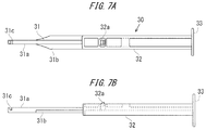
- FIG. 7 illustrates the schematic configuration of the plunger 30.
- a longitudinal length of the plunger 30 is set slightly larger than that of the nozzle body 10.
- the plunger 30 is formed of: an operating member 31 which is disposed on a distal end side and basically has a circular columnar shape; and an insertion member 32 which is disposed on a rear end side and basically has a rectangular rod shape.
- the operating member 31 is configured to include: a circular columnar member 31a having a circular columnar shape; and thin-plate-shaped flat members 31b expanding in the lateral direction from the circular columnar member 31a.
- a notch member 31c is formed on a distal end portion of the operating member 31.
- the notch member 31c is formed on the operating member 31 in a groove shape such that notch member 31c opens upward and penetrates the operating member 31 in a lateral direction.
- a groove wall disposed on a distal end side of the notch member 31c is formed of an inclined surface which extends upward as the inclined surface extends toward the distal end side of the operating member 31.
- the insertion member 32 has an approximately H-shaped cross section as a whole, and a size of the insertion member 32 in the lateral direction and a size of the insertion member 32 in the vertical direction are set slightly smaller than those of the through-hole 10c formed in the nozzle body 10.
- a disc-shaped pushing plate member 33 which expands in the vertical direction as well as in the lateral direction is formed on a rear end of the insertion member 32.
- a pawl member 32a which projects toward an upper side of the insertion member 32 and is vertically movable due to elasticity of a raw material of the plunger 30 is formed on a portion of the insertion member 32 on a distal end side from the center in the longitudinal direction.
- the position where the pawl member 32a is formed and the position where the engaging hole 10e is formed are set such that, in an engaging state, a distal end of the operating member 31 is positioned behind the lens body 2a of the intraocular lens 2 set on the stage member 12, and the support members 2b on a rear side of the lens body 2a can be supported by the notch member 31c from below.
- the plunger 30 is arranged at an initial position in a state where the plunger 30 is inserted into the nozzle body 10.
- the positioning member 50 is mounted on the nozzle body 10 from below the setting surface 12b. With such a configuration, the first placing members 54, 54 and the second placing members 56, 56 of the positioning member 50 are held in a proj ecting manner from the setting surface 12b.
- the lens body 2a of the intraocular lens 2 is placed and positioned on the upper surfaces of the first placing members 54, 54 and the upper surfaces of the second placing members 56, 56 in a state where the support members 2b, 2b are directed in the longitudinal direction of the nozzle body 10.
- the support member 2b on a rear side of the intraocular lens 2 is supported by a bottom surface of the notch member 31c of the plunger 30.
- FIG. 8A is a top plan diagram of the insertion member 20
- FIG. 8B is a cross-sectional diagram of the insertion member 20 taken along a line A-A in FIG. 8A .
- a cross sectional member is indicated by hatching.
- the guide wall member 20b of the insertion member 20 is configured such that an outer wall 21 and an inner wall 22 of the guide wall member 20b surround the needle hole 20a in an arcuate shape when the guide wall member 20b is viewed from above the stage lid member 13.
- a user can grasp the position of the needle hole 20a by confirming the position of the guide wall member 20b. In this manner, the guide wall member 20b has an effect of enhancing visibility of the needle hole 20a.
- the needle hole 20a is arranged at the position closer to the guide wall member 20b than an arcuate opening member 23 which the guide wall member 20b forms. Further, the center O of an arc which the inner wall 22 of the guide wall member 20b forms is offset from the center O' of the needle hole 20a. Accordingly, when the distal end of the needle of a syringe is brought into contact with the guide wall member 20b, a user can guide a distal end of a needle to an area in the vicinity of the needle hole 20a along the inner wall 22 of the guide wall member 20b.
- the guide wall member 20b has an arcuate shape when viewed from above the stage lid member 13.
- the guide wall member 20b has a function of guiding a needle of a syringe to the needle hole 20a
- the guide wall member may have any arbitrary shape and is configured such that the center (the center of gravity) of the guide wall member and the center of the needle hole 20a on the upper surface of the stage lid member 13 do not agree with each other.
- the guide wall member 20b extends substantially perpendicular to an upper surface 13d of the stage lid member 13.
- a thickness of the guide wall member 20b is suitably set such that a needle of a syringe to be used does not penetrate the guide wall member 20b.
- a height of the guide wall member 20b from the upper surface 13d is suitably set to an extent that a user can confirm the guide wall member 20b by his naked eyes.
- a thickness of the guide wall member 20b can be set to 0.5 mm, and a height of the guide wall member 20b from the upper surface 13d can be set to 1.5 mm.
- a diameter of an arc which the inner wall 22 forms can be set to 2.0 mm, for example.
- the inclined member 20c has a funnel shape.
- the inclined member 20c is connected with the inner wall 22 of the guide wall member 20b at an upper end thereof, and is connected with an inner surface of the needle hole 20a at a lower end thereof.
- the inclined member 20c is formed on the insertion hole 20. Accordingly, a user can guide a distal end of a needle to the needle hole 20a from the inclined member 20c by enabling sliding of the distal end of the needle not only in the case where a distal end of a needle of a syringe is brought into contact with the inner wall 22 but also in the case where the distal end of the needle of the syringe is brought into contact with the inclined member 20c.
- FIG. 9 illustrates one example of the positional relationship between the intraocular lens 2, the insertion member 20 and a needle 60 of a syringe when the needle 60 is inserted into the stage member 12 through the needle hole 20a after the intraocular lens 2 is set on the stage member 12 and the stage lid member 13 is closed.
- FIG. 9 illustrates a state where the needle 60 of the syringe is brought into contact with the guide wall member 20b.
- a portion of the intraocular lens 2 is indicated by a solid line.
- the intraocular lens 2 is accommodated in the accommodating member formed of the stage member 12 and the stage lid member 13.
- an inclination angle of the needle 60 of the syringe with respect to a direction perpendicular to the upper surface 13d of the stage lid member 13 is restricted to a value which falls within a predetermined range by the guide wall member 20b.
- the predetermined range within which the inclination angle is restricted is determined based on a height of the guide wall member 20b, a relative position between the guide wall member 20b and the needle hole 20a, a diameter of the needle hole 20a and the like.
- the guide wall member 20b is configured such that the guide wall member 20b is formed into an arcuate shape as viewed from above the stage lid member 13 so that the guide wall member 20b does not completely surround the needle hole 20a and has the opening member 23. With such a configuration, the needle 60 of the syringe can be easily guided to the needle hole 20a.
- a portion of the guide wall member 20b is opened and hence, after the needle 60 of the syringe is inserted into the needle hole 20a, the movement of the needle 60 of the syringe is not restricted by the guide wall member 20b at the opening member 23. Accordingly, the movement of the needle 60 of the syringe is allowed to an extent that the needle 60 is not brought into contact with the lens body 2a of the intraocular lens 2, and hence, the degree of freedom in movement of the needle 60 of the syringe can be also enhanced.
- the opening member 23 of the guide wall member 20b is formed on the upper surface 13d of the stage lid member 13 in a direction perpendicular to the fore-and-aft direction (longitudinal direction) of the nozzle body 10.
- a user inserts the needle 60 of the syringe through the needle hole 20a and injects a hyaluronic acid into the stage member 12 and, thereafter, the user removes the positioning member 50 from the nozzle body 10.
- the first placing members 54, 54 and the second placing members 56, 56 which support the lens body 2a of the intraocular lens 2 are retracted from the setting surface 12b, and the intraocular lens 2 is placed on the setting surface 12b in a movable manner.
- the distal end member 10a of the nozzle member 15 of the nozzle body 10 is inserted into an incision formed in an ophthalmic tissue.
- the distal end member 10a has an oblique opening shape and hence, the insertion of the distal end member 10a into the incision can be easily performed.
- the nozzle member 15 is inserted into the incision and, thereafter, the pushing plate member 33 of the plunger 30 is pushed toward a distal end side of the nozzle body 10 in such a state.
- a distal end of the operating member 31 of the plunger 30 is brought into contact with the outer periphery of the lens body 2a of the intraocular lens 2 which is set on the setting surface 12b, and the intraocular lens 2 is guided toward the distal end member 10a by the plunger 30, and is released into the inside of an eyeball through the opening of the distal end member 10a.
- the guide wall member 20b of the insertion member 20 is formed into an arcuate shape when the guide wall member 20b is viewed from above the stage lid member 13.
- a shape of the guide wall member 20b is not limited to the above-mentioned shape and can be suitably changed. Also in the description of the following modifications made hereinafter, the shapes of respective guide wall members can be suitably changed.
- FIG. 10 is a perspective diagram illustrating the schematic configuration of an insertion member 200 according to a modification 1.
- the insertion member 200 has a needle hole 20a, a guide wall member 200b, and an inclined member 200c.
- a shape of an outer wall 201 of the guide wall member 200b as viewed from above a stage lid member 13 is equal to the shape of the outer wall of the guide wall member 200b in the above-mentioned embodiment, and an opening member 203 which corresponds to the opening member 23 of the above-mentioned embodiment is formed on the guide wall member 200b.
- the needle hole 20a is formed in an upper surface of the stage lid member 13 at the position closer to an inner wall 202 of the guide wall member 200b than the opening member 203.
- the inner wall 202 of the guide wall member 200b is formed in an approximately V shape as viewed from above the stage lid member 13.
- the inclined member 200c is equal to the inclined member 20c of the above-mentioned embodiment except for that the inclined member 200c is formed into an arcuate shape defined by the inner wall 202 and the needle hole 20a.
- the guide wall member 200b of the insertion member 200 As illustrated in FIG. 10 , even when the guide wall member 200b is disposed adjacent to the needle hole 20a, a user can use the guide wall member 200b of the insertion member 200 as an index indicating the position of the needle hole 20a.
- the guide wall member 200b and the inclined member 200c play a role of guiding a needle of a syringe to the needle hole 20a. Further, after a needle of a syringe is inserted into the needle hole 20a, the movement of the needle is restricted by the guide wall member 200b such that the needle is not brought into contact with the lens body 2a of the intraocular lens 2.
- FIG. 11 is a perspective diagram illustrating the schematic configuration of an insertion member 300 according to a modification 2.
- a height of the guide wall member 200b on an inner wall 202 side in a thickness direction in the modification 1 is set lower than a height of the guide wall member 200b on an outer wall 201 side.
- a stepped member formed of an upper surface 300d, an R member 300e and a second inner wall 302b is formed on a guide wall member 300b.
- An inclined member 300c and an opening member 303 respectively correspond to the inclined member 200c and the opening member 203 in the modification 1.
- a user can use the guide wall member 300b of the insertion member 300 as an index indicating the position of a needle hole 20a. Further, after a needle of a syringe is inserted into the needle hole 20a, the movement of the needle is restricted by the guide wall member 300b such that the needle is not brought into contact with the lens body 2a of the intraocular lens 2.
- the second inner wall 302b which is a stepped member formed on the guide wall member 300b also plays a role of guiding a needle of a syringe to the needle hole 20a. Further, the movement of the needle of the syringe inserted into the needle hole 20a is restricted also by the stepped member.
- a wall thickness of the member can be reduced in so-called injection molding.
- the modification 2 can also acquire an effect of preventing occurrence of shrinkage at the time of forming the insertion member by injection molding.
- FIG. 12A and FIG. 12B are diagrams illustrating the schematic configuration of an insertion member 400 according to a modification 3.
- an X axis and a Y axis which are orthogonal to each other are set on a plane parallel to an upper surface of a stage lid member 13.
- FIG. 12A is a perspective diagram
- FIG. 12B is a plan diagram.
- a guide wall member 400b is a flat-plate-shaped wall formed at a position adjacent to a needle hole 20a.
- the position of the guide wall member 400b and the like may be suitably set corresponding to the positional relationship between the needle hole 20a and a lens body 2a of a positioned intraocular lens. Also in the modification 3, a user can use the guide wall member 400b as an index indicating the position of the needle hole 20a. Further, when a needle of a syringe is inserted into the needle hole 20a, the movement of the needle of the syringe is restricted by the guide wall member 400b such that the needle of the syringe is not brought into contact with the lens body 2a.
- FIG. 13A and FIG. 13B are diagrams illustrating the schematic configuration of an insertion member 500 according to a modification 4.
- FIG. 13A is a perspective diagram
- FIG. 13B is a plan diagram.
- a guide wall member 500b is formed in a region which annularly surrounds the periphery of a needle hole 20a.
- the needle hole 20a and an outer wall and an inner wall of the guide wall member 500b are configured to be arranged concentrically (the center O").
- a user can use the guide wall member 500b as an index indicating the position of the needle hole 20a.
- the movement of the needle of the syringe is restricted by the guide wall member 500b such that the needle of the syringe is not brought into contact with the lens body 2a.
- FIG. 14A and FIG. 14B are diagrams illustrating the schematic configuration of an insertion member 600 according to a modification 5.
- FIG. 14A is a perspective diagram
- FIG. 14B is a plan diagram.
- the insertion member 600 in the modification 5 has substantially the same configuration as the insertion member 500 except for that the center of the insertion member 500 in the modification 4 is offset from the center of the needle hole 20a. That is, in the modification 5, as viewed in a plan diagram, the needle hole 20a is configured such that a distance L between the needle hole 20a and a predetermined portion of an inner wall 602 of a guide wall member 600b is set shorter than a distance between the needle hole 20a and other portions of the inner wall 602.
- predetermined portion is determined by taking into account the easiness of guiding a needle of a syringe to the needle hole 20a and the proper restriction of the movement of a needle of a syringe so as to prevent the needle of the syringe from being brought into contact with the lens body 2a and the like.
- a user can use the guide wall member 600b as an index indicating the position of the needle hole 20a. Further, when a needle of a syringe is inserted into the needle hole 20a, the movement of the needle of the syringe is restricted by the guide wall member 600b such that the needle of the syringe is not brought into contact with the lens body 2a.
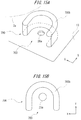
- FIG. 15A and FIG. 15B are diagrams illustrating the schematic configuration of an insertion member 700 according to a modification 6.
- FIG. 15A is a perspective diagram
- FIG. 15B is a plan diagram.
- an approximately U-shaped guide wall member 700b having an opening member 703 is formed in the insertion member 700 of the modification 6.
- the guide wall member 700b is arranged so as to surround a needle hole 20a.
- the position of the guide wall member 700b and the position of the opening member 703 with respect to a position of the needle hole 20a are determined by taking into account the easiness of guiding a needle of a syringe to the needle hole 20a and the proper restriction of the movement of the needle of the syringe so as to prevent the needle of the syringe from coming into contact with the lens body 2a and the like. Also in the modification 6, a user can use the guide wall member 600b as an index indicating the position of the needle hole 20a. Further, by forming the opening member 703, compared to cases described in the modifications 4, 5 where the opening member 703 is not formed, the user can more easily guide the needle of the syringe to the needle hole 20a.
- an inclined member substantially equal to the inclined members 20c, 200c, 300c can be formed between the guide wall member and the needle hole 20a.
Landscapes
- Health & Medical Sciences (AREA)
- Ophthalmology & Optometry (AREA)
- Cardiology (AREA)
- Oral & Maxillofacial Surgery (AREA)
- Transplantation (AREA)
- Engineering & Computer Science (AREA)
- Biomedical Technology (AREA)
- Heart & Thoracic Surgery (AREA)
- Vascular Medicine (AREA)
- Life Sciences & Earth Sciences (AREA)
- Animal Behavior & Ethology (AREA)
- General Health & Medical Sciences (AREA)
- Public Health (AREA)
- Veterinary Medicine (AREA)
- Prostheses (AREA)
Abstract
Description
- The embodiments discussed herein pertain to an intraocular lens insertion apparatus.
- Intraocular lenses are widely used to be replaced with human opacity crystalline lenses in cataract treatments or normal human crystalline lenses for compensating the optical powers of the lenses. In intraocular lens insertion surgeries for the cataract treatments, a discission wound (cut) which is several millimeters in length is produced at the edge of the cornea, the human crystalline lens is crushed and removed by phacoemulsification and aspiration etc. and the intraocular lens is inserted and fixed in the eye, for example.
- Recently, in inserting an intraocular lens into the inside of an eyeball through the incision, it is often the case that a so-called preload (or preset) type insertion apparatus is used where the intraocular lens is placed in an accommodating member in advance. A user inserts a distal end opening of an inserting sleeve member formed on a distal end member of an apparatus body into the inside of an eyeball through the above-mentioned incision, and also in a state where the intraocular lens is deformed into a compact shape in the inside of the apparatus body, the intraocular lens is pushed out by a rod-like plunger through the distal end opening of the inserting sleeve member so that the intraocular lens is released and inserted into the inside of the eyeball. With the use of such an insertion apparatus, an intraocular lens can be easily inserted into an eyeball by making use of an incision which is formed for taking out and removing a crystalline lens. Accordingly, an operation can be simplified and, at the same time, the occurrence of astigmatism and the occurrence of an infectious disease after the operation can be suppressed.
- In inserting an intraocular lens into an eyeball using the above-mentioned insertion apparatus, with an aim to enable smooth movement of the intraocular lens in the inside of the insertion apparatus toward the distal end opening of the inserting sleeve member, there may be a case where viscoelastic material such as hyaluronic acid is injected into the inside of the insertion apparatus as a lubricant for the intraocular lens, and the viscoelastic material is interposed between the intraocular lens and an inner wall of the insertion apparatus. With such a configuration, friction resistance between the intraocular lens and the insertion apparatus is reduced thus enabling the smoother movement of the intraocular lens in the inside of the insertion apparatus. Further, in injecting the viscoelastic material into the inside of the insertion apparatus, a needle of a syringe is inserted into the inside of the insertion apparatus through a hole formed in the insertion apparatus, and the viscoelastic material is injected into particularly a place where the intraocular lens is accommodated in the inside of the insertion apparatus by the syringe.
- [PTL 1]
JP-A-2011-255029 - In the conventional insertion apparatus, however, the hole through which the needle of the syringe is inserted is barely visible and hence, it is often the case that whether or not the needle of the syringe can be skillfully advanced into the inside of the insertion apparatus through the hole depends on experience and sense of touch of a user.
- The technique of this disclosure has been made in view of the above-mentioned circumstances, and it is an obj ect of this disclosure to realize an insertion apparatus which supports the injection of a lubricant into an accommodating member for an intraocular lens.
- According to an embodiment, it is provided an intraocular lens insertion apparatus, including an accommodating member integrally or independently formed on an apparatus body which is inserted into an eyeball, allowing arrangement of the intraocular lens in the apparatus body by accommodating the intraocular lens therein, and having a hole through which a needle of a syringe which supplies a lubricant to the intraocular lens passes; and a guide wall member formed on the accommodating member at a position adjacent to the hole, and being configured to guide the needle of the syringe to the hole. With such a configuration, in injecting a lubricant for the intraocular lens into the accommodating member, a user can guide the needle of the syringe in which a lubricant is filled to the hole by the guide wall member while checking the hole.
- Further, the guide wall member is configured so as to prevent the needle of the syringe from coming into contact with a lens body of the intraocular lens accommodated in the accommodating member in a state where the needle of the syringe which is made to pass through the hole is brought into contact with the guide wall.
- Further, at least a part of the guide wall member is configured to surround the hole. A distance from the center of the hole to a predetermined portion of an inner wall of the guide wall member may be set shorter than a distance from the center of the hole to the other portion of the inner wall of the guide wall member. The guide wall member has an opening member which allows movement of the needle of the syringe within a range where the needle of the syringe which is made to pass through the hole is not brought into contact with a lens body of the intraocular lens accommodated in the accommodating member. An inclined member which connects an inner wall of the guide wall member and the hole may be formed on the guide wall member. Further, a stepped member may be formed on the guide wall member by setting a height of an inner wall side of the guide wall member in a thickness direction lower than a height of an outer wall of the guide wall member. With such a configuration, the user can more easily guide the needle of the syringe to the hole.
- Further, the hole is formed on a distal end side of the apparatus body with respect to the intraocular lens accommodated in the accommodating member. With such a configuration, when a lubricant is injected from the needle of the syringe which is inserted into the hole, the lubricant can be injected toward a more distal end side of the insertion sleeve member with respect to the intraocular lens. Accordingly, in moving the intraocular lens toward the distal end of the inserting sleeve member, a lubricant can be supplied to the intraocular lens with more certainty.
- In addition, an intraocular lens insertion apparatus may include: an accommodating member integrally or independently formed on an apparatus body which is inserted into an eyeball, allowing arrangement of the intraocular lens in the apparatus body by accommodating the intraocular lens therein, and having a hole through which a needle of a syringe which supplies a lubricant to the intraocular lens passes; and a guide wall member formed on the accommodating member at a position adjacent to the hole, and being configured to guide the needle of the syringe to the hole, wherein the intraocular lens is accommodated in the accommodating member before the insertion apparatus is placed on a market.
- According to the technique disclosed herein, it is possible to realize the insertion apparatus which can inject a lubricant into an insertion member of an intraocular lens more easily compared to the prior art.
-
-
FIG. 1 is a diagram illustrating the schematic configuration of an intraocular lens insertion apparatus according to one embodiment; -
FIG. 2 is a diagram illustrating the schematic configuration of an insertion member for a needle of a syringe according to one embodiment; -
FIG. 3A and FIG. 3B are diagrams illustrating the schematic configuration of the intraocular lens insertion apparatus according to one embodiment; -
FIG. 4A and FIG. 4B are diagrams illustrating the schematic configuration of an intraocular lens according to one embodiment; -
FIG. 5 is a diagram illustrating the schematic configuration of a nozzle body according to one embodiment; -
FIG. 6A and FIG. 6B are diagrams illustrating the schematic configuration of a positioning member according to one embodiment; -
FIG. 7A and FIG. 7B are diagrams illustrating the schematic configuration of a plunger according to one embodiment; -
FIG. 8A is a plan diagram illustrating the schematic configuration of the insertion member for the needle of the syringe according to one embodiment, andFIG. 8B is a cross-sectional diagram of the configuration illustrated inFIG. 8A ; -
FIG. 9 is a diagram illustrating the schematic positional relationship between the needle of the syringe, a needle hole, and the intraocular lens according to one embodiment; -
FIG. 10 is a diagram illustrating the schematic configuration of an insertion member for a needle of a syringe according to amodification 1; -
FIG. 11 is a diagram illustrating the schematic configuration of an insertion member for a needle of a syringe according to amodification 2; -
FIG. 12A and FIG. 12B is a diagram illustrating the schematic configuration of an insertion member for a needle of a syringe according to a modification 3; -
FIG. 13A and FIG. 13B is a diagram illustrating the schematic configuration of an insertion member for a needle of a syringe according to a modification 4; -
FIG. 14A and FIG. 14B is a diagram illustrating the schematic configuration of an insertion member for a needle of a syringe according to a modification 5; and -
FIG. 15A and FIG. 15B is a diagram illustrating the schematic configuration of an insertion member for a needle of a syringe according to a modification 6. - Hereinafter, an embodiment of the present invention is described with reference to drawings.
-
FIG. 1 is a perspective diagram illustrating a whole intraocularlens insertion apparatus 1 of the present embodiment (hereinafter, also simply referred to as an insertion apparatus 1). Theinsertion apparatus 1 includes anozzle body 10 which forms an apparatus body, aplunger 30 which forms a push member for pushing an intraocular lens, and astage member 12 and astage lid member 13 which form an accommodating member for accommodating an intraocular lens. Thestage member 12 is integrally or independently formed on thenozzle body 10. Theplunger 30 is inserted into thenozzle body 10. Anintraocular lens 2 is set in thestage member 12. Thestage member 12 is integrally formed with thestage lid member 13.FIG. 1 illustrates a state where thestage lid member 13 is opened. Further,FIG. 1 illustrates an upper surface of thestage lid member 13. Aninsertion member 20 for a needle of a syringe filled with a lubricant for the intraocular lens is formed on thestage lid member 13. Setting surface through-holes 12c for assembling a positioningmember 50 for positioning theintraocular lens 2 are formed in thenozzle body 10. The detailed configuration of the positioningmember 50 is described later. As can be understood from the description made hereinafter with reference toFIG. 3 ,FIG. 1 is a perspective diagram when the intraocularlens insertion apparatus 1 is viewed from below. Accordingly, theinsertion member 20 is configured to project toward the outside of thestage lid member 13 when thestage lid member 13 is closed. -
FIG. 2 illustrates an enlarged diagram of theinsertion member 20 for a needle of a syringe inserted. As illustrated inFIG. 2 , theinsertion member 20 has: aneedle hole 20a which is a hole into which a needle of a syringe is inserted; and aguide wall member 20b which guides a distal end of the needle of the syringe into theneedle hole 20a. As described later, theguide wall member 20b also has a function of restricting the movement, the inclination, the rotation and the like of a needle of a syringe after the needle is inserted into theneedle hole 20a. Further, aninclined member 20c which extends downward toward theneedle hole 20a is formed on thestage lid member 13 at a region surrounded by theguide wall member 20b. Theintraocular lens 2 is placed and positioned on thestage member 12. When the positioning of theintraocular lens 2 with respect to thestage member 12 is completed, thestage lid member 13 is closed by rotating thestage lid member 13 about a connectingmember 14 between thestage lid member 13 and thestage member 12. - Next, when the
plunger 30 is pushed into anozzle body 10 side, theplunger 30 is brought into contact with theintraocular lens 2 placed on thestage member 12. When theplunger 30 is further pushed into thenozzle body 10 side, theintraocular lens 2 is moved to adistal end member 10a of thenozzle body 10 from thestage member 12 through anozzle member 15 connected with thestage member 12. Then, theintraocular lens 2 is pushed out through an opening of thedistal end member 10a. -
FIG. 3A and FIG. 3B illustrate the schematic configuration of theinsertion apparatus 1 of the present embodiment.FIG. 3A is a plan diagram of theinsertion apparatus 1 when thestage lid member 13 is opened, andFIG. 3B is a side diagram of theinsertion apparatus 1 when thestage lid member 13 is closed. Thenozzle body 10 of theinsertion apparatus 1 is formed as a tube with an approximately rectangular cross section, an end member of thenozzle body 10 on one side is largely opened (hereinafter, the largely-opened side is referred to as arear end member 10b), and anozzle member 15 which forms a tapered insertion cylindrical member and thedistal end member 10a are formed on an end member of thenozzle body 10 on the other side. As illustrated inFIG. 3B , thedistal endmember 10a has an obliquely formed opening. Theplunger 30 is inserted into thenozzle body 10 and is movable in an extensible and retractable manner. - In the description made hereinafter, the direction extending toward the
distal end member 10a from therear end member 10b of thenozzle body 10 is assumed as the frontward direction, the direction opposite to the frontward direction is assumed as the rearward direction, the direction toward a viewer's side with respect to a paper surface on whichFIG. 3A is drawn is assumed as the upward direction, the direction opposite to the upward direction is assumed as the downward direction, the direction toward a viewer's side with respect to a paper surface on whichFIG. 3B is drawn is assumed as the leftward direction, and the direction opposite to the leftward direction is assumed as the rightward direction. In this case, an upper side corresponds to a front side along an optical axis of alens body 2a described later, a lower side corresponds to a rear side along the optical axis of thelens body 2a, a front side corresponds to a front side in the pushing direction of theplunger 30, and a rear side corresponds to a rear side in the pushing direction of theplunger 30. - A
hold member 11 which projects in a plate shape and on which a user hooks his fingers when he pushes theplunger 30 toward the distal end side of thenozzle body 10 is integrally formed on thenozzle body 10 in the vicinity of therear end member 10b of thenozzle body 10. Thestage member 12 on which theintraocular lens 2 is to be set is formed on a member of thenozzle body 10 behind thenozzle member 15. Thestage member 12 is configured such that an upper side of thenozzle body 10 is opened by opening thestage lid member 13. The positioningmember 50 is mounted on thestage member 12 from below thenozzle body 10. With the use of the positioningmember 50, theintraocular lens 2 is stably held in thestage member 12 even before theinsertion apparatus 1 is used (during transportation). - That is, in the
insertion apparatus 1, at the time of manufacturing theinsertion apparatus 1, theintraocular lens 2 is set on thestage member 12 such that a front side along an optical axis is directed upward in a state where thestage lid member 13 is opened and the positioningmember 50 is mounted on thestage member 12. Then, theinsertion apparatus 1 is shipped after thestage lid member 13 is closed, and theinsertion apparatus 1 is sold. Then, at the time of using theinsertion apparatus 1, a user inserts a needle of a syringe filled with a lubricant for an intraocular lens into the inside of thestage member 12 through theneedle hole 20a of theinsertion member 20 and injects the lubricant. Then, the user removes the positioningmember 50 while holding thestage lid member 13 in a closed state and, thereafter, pushes theplunger 30 toward the distal end side of thenozzle body 10. Due to such an operation, theintraocular lens 2 is pushed by theplunger 30 so as to move theintraocular lens 2 to thenozzle member 15, and theintraocular lens 2 is released into the inside of an eyeball from thedistal end member 10a. In theinsertion apparatus 1, thenozzle body 10, theplunger 30, and the positioningmember 50 are formed using a resin such as polypropylene. Polypropylene has been proven as a material used for medical apparatuses. In addition, polypropylene is reliable in chemical resistance etc. -
FIG. 4A and FIG. 4B are diagrams illustrating the schematic configuration of theintraocular lens 2.FIG. 4A is a plan diagram, andFIG. 4B is a side diagram. Theintraocular lens 2 is a so-called three-piece type intraocular lens. Theintraocular lens 2 is formed of thelens body 2a having a predetermined refractivity, and two whisker-like support members lens body 2a and are provided for holding thelens body 2a in the inside of an eyeball. Both thelens body 2a and thesupport members 2b are formed using a flexible resin material. As a matter of course, the present invention is also applicable to an insertion apparatus for inserting a so-called one-piece-type intraocular lens where a support member and an optical member are formed into one member by molding. In the inside of theinsertion apparatus 1 of the present embodiment, theintraocular lens 2 is set such that one of twosupport members lens body 2a, and the other of twosupport members lens body 2a. -
FIG. 5 is a plan diagram of thenozzle body 10. As described previously, in thenozzle body 10, theintraocular lens 2 is set on thestage member 12. In such a state, theintraocular lens 2 is pushed by theplunger 30, and is released from thedistal end member 10a. Here, a through-hole 10c whose cross-sectional shape changes corresponding to a change in a profile of thenozzle body 10 is formed in the inside of thenozzle body 10. In the release of theintraocular lens 2, theintraocular lens 2 is deformed corresponding to a change in a cross-sectional shape of the through-hole 10c formed in the inside of thenozzle body 10, and is released after being deformed into a shape which facilitates the entrance of theintraocular lens 2 into the incision formed in an eyeball of a patient. - The
distal end member 10a has an obliquely cut shape such that an upper region of thenozzle member 15 extends more toward a front side than a lower region of thenozzle member 15. The obliquely cut shape of thedistal end member 10a may be formed by obliquely cutting thedistal end member 10a so as to have a straight line shape as viewed from a lateral direction or may be formed by obliquely cutting thedistal end member 10a so as to have an outwardly bulging shape or a curved surface shape. - A
stage groove 12a having a width slightly larger than a diameter of thelens body 2a of theintraocular lens 2 is formed on thestage member 12. A size of thestage groove 12a in the longitudinal direction is set larger than a total size of theintraocular lens 2 including thesupport members intraocular lens 2. A settingsurface 12b is formed of a bottom surface of thestage groove 12a. The position of the settingsurface 12b in a vertical direction is set higher than the height position of a bottom surface of the through-hole 10c formed in thenozzle body 10, and thesetting surface 12b and the bottom surface of the through-hole 10c are connected to each other by a bottom member inclinedsurface 10d. - The
stage member 12 and thestage lid member 13 are integrally formed with each other. A size of thestage lid member 13 in the longitudinal direction is set substantially equal to a size of thestage member 12 in the longitudinal direction. Thestage lid member 13 is connected to thestage member 12 by a thin-plate-like connectingmember 14 which is formed in an extending manner toward thestage lid member 13 side from a side surface of thestage member 12. The connectingmember 14 is formed in a bendable manner at a center portion thereof, and thestage lid member 13 overlaps with thestage member 12 from above by bending the connectingmember 14 so that thestage lid member 13 is closed. - In the
stage lid member 13,ribs 13a and arib 13b for reinforcing thestage lid member 13 and for stabilizing the position of theintraocular lens 2 are formed on a surface of thestage lid member 13 which faces the settingsurface 12b in an opposed manner in a lid closed state.Guide projections 13c are formed on thestage lid member 13 as an upper guide for theplunger 30. Further, theneedle hole 20a is formed in thestage lid member 13 as an insertion hole for injecting a hyaluronic acid into thestage member 12 using a syringe before an operation of inserting theintraocular lens 2 into the inside of an eyeball is performed. Theneedle hole 20a is a hole which connects the outside of thestage member 12 and theintraocular lens 2 accommodated in thestage member 12 to each other when thestage lid member 13 is closed. A user inserts a needle of a syringe through theneedle hole 20a before the insertion operation of theintraocular lens 2 is performed, and supplies a hyaluronic acid to the necessary position in the inside of thestage member 12. - The positioning
member 50 is detachably mounted on a lower side of the settingsurface 12b of thestage member 12.FIG. 6A and FIG. 6B illustrate schematic configuration of the positioningmember 50.FIG. 6A is a plan diagram of the positioningmember 50, andFIG. 6B is a left side diagram of the positioningmember 50. The positioningmember 50 is formed as a body separate from thenozzle body 10, and is configured such that a pair ofside wall members member 52. Holdingmembers side wall members 51 respectively. - A pair of
first placing members side wall members First positioning members first placing members first positioning members lens body 2a of theintraocular lens 2. - A pair of
second placing members member 52 in a longitudinal direction. A height of upper surfaces of thesecond placing members first placing members Second positioning members second placing members second positioning members second placing members second positioning members lens body 2a of theintraocular lens 2. In addition, engagingpawls second placing members - The above-mentioned
positioning member 50 is assembled to thenozzle body 10 from below the settingsurface 12b of thenozzle body 10. The setting surface through-holes 12c which penetrate thesetting surface 12b in a thickness direction are formed in thesetting surface 12b of thenozzle body 10. Profiles of the setting surface through-holes 12c have a shape slightly larger than and substantially similar to a shape of thefirst placing members second placing members member 50 as viewed from above. When the positioningmember 50 is mounted on thenozzle body 10, thefirst placing members second placing members holes 12c from below the settingsurface 12b, and project upward from the settingsurface 12b. - At this stage of operation, the engaging
pawls second positioning members surface 12b through the setting surface through-holes 12c, and are engaged with the upper surface of the settingsurface 12b. With such a configuration, the positioningmember 50 is assembled to thenozzle body 10 from below, and thefirst placing members second placing members setting surface 12b in a state where thefirst placing members second placing members surface 12b. Then, in setting theintraocular lens 2 on thesetting surface 12b, a bottom surface of an outer peripheral portion of thelens body 2a is placed on the upper surfaces of thefirst placing members second placing members lens body 2a in a horizontal direction (a direction horizontal to thesetting surface 12b) is restricted by thefirst positioning members second positioning members -
FIG. 7 illustrates the schematic configuration of theplunger 30. A longitudinal length of theplunger 30 is set slightly larger than that of thenozzle body 10. Theplunger 30 is formed of: an operatingmember 31 which is disposed on a distal end side and basically has a circular columnar shape; and aninsertion member 32 which is disposed on a rear end side and basically has a rectangular rod shape. The operatingmember 31 is configured to include: acircular columnar member 31a having a circular columnar shape; and thin-plate-shapedflat members 31b expanding in the lateral direction from thecircular columnar member 31a. - A
notch member 31c is formed on a distal end portion of the operatingmember 31. As can be understood fromFIG. 7A and FIG. 7B , thenotch member 31c is formed on the operatingmember 31 in a groove shape such thatnotch member 31c opens upward and penetrates the operatingmember 31 in a lateral direction. As can be understood fromFIG. 7B , a groove wall disposed on a distal end side of thenotch member 31c is formed of an inclined surface which extends upward as the inclined surface extends toward the distal end side of the operatingmember 31. - On the other hand, the
insertion member 32 has an approximately H-shaped cross section as a whole, and a size of theinsertion member 32 in the lateral direction and a size of theinsertion member 32 in the vertical direction are set slightly smaller than those of the through-hole 10c formed in thenozzle body 10. A disc-shaped pushingplate member 33 which expands in the vertical direction as well as in the lateral direction is formed on a rear end of theinsertion member 32. - A
pawl member 32a which projects toward an upper side of theinsertion member 32 and is vertically movable due to elasticity of a raw material of theplunger 30 is formed on a portion of theinsertion member 32 on a distal end side from the center in the longitudinal direction. When theplunger 30 is inserted into thenozzle body 10, an engaginghole 10e illustrated inFIG. 3 which is formed in the upper surface of thenozzle body 10 in a thickness direction and thepawl member 32a are engaged with each other. With such engagement, the relative position between thenozzle body 10 and theplunger 30 in an initial state is determined. The position where thepawl member 32a is formed and the position where the engaginghole 10e is formed are set such that, in an engaging state, a distal end of the operatingmember 31 is positioned behind thelens body 2a of theintraocular lens 2 set on thestage member 12, and thesupport members 2b on a rear side of thelens body 2a can be supported by thenotch member 31c from below. - Before the
intraocular lens 2 is accommodated in theinsertion apparatus 1 having the above-mentioned configuration, theplunger 30 is arranged at an initial position in a state where theplunger 30 is inserted into thenozzle body 10. As described previously, the positioningmember 50 is mounted on thenozzle body 10 from below the settingsurface 12b. With such a configuration, thefirst placing members second placing members member 50 are held in a proj ecting manner from the settingsurface 12b. - Next, the
lens body 2a of theintraocular lens 2 is placed and positioned on the upper surfaces of thefirst placing members second placing members support members nozzle body 10. In such a state, thesupport member 2b on a rear side of theintraocular lens 2 is supported by a bottom surface of thenotch member 31c of theplunger 30. - In inserting the
intraocular lens 2 into an eyeball using theinsertion apparatus 1, firstly, an hyaluronic acid which is a lubricant for theintraocular lens 2 is injected into a position where the hyaluronic acid is necessary by inserting a needle of a syringe through theneedle hole 20a. Here, theinsertion member 20 of the present embodiment is described with reference toFIG. 8A and FIG. 8B. FIG. 8A is a top plan diagram of theinsertion member 20, andFIG. 8B is a cross-sectional diagram of theinsertion member 20 taken along a line A-A inFIG. 8A . InFIG. 8B , a cross sectional member is indicated by hatching. As illustrated inFIG. 8A , theguide wall member 20b of theinsertion member 20 is configured such that anouter wall 21 and aninner wall 22 of theguide wall member 20b surround theneedle hole 20a in an arcuate shape when theguide wall member 20b is viewed from above thestage lid member 13. At the time of inserting a needle of a syringe into the inside of theneedle hole 20a, a user can grasp the position of theneedle hole 20a by confirming the position of theguide wall member 20b. In this manner, theguide wall member 20b has an effect of enhancing visibility of theneedle hole 20a. - As can be understood from
FIG. 8A , theneedle hole 20a is arranged at the position closer to theguide wall member 20b than anarcuate opening member 23 which theguide wall member 20b forms. Further, the center O of an arc which theinner wall 22 of theguide wall member 20b forms is offset from the center O' of theneedle hole 20a. Accordingly, when the distal end of the needle of a syringe is brought into contact with theguide wall member 20b, a user can guide a distal end of a needle to an area in the vicinity of theneedle hole 20a along theinner wall 22 of theguide wall member 20b. In the present embodiment, theguide wall member 20b has an arcuate shape when viewed from above thestage lid member 13. However, provided that theguide wall member 20b has a function of guiding a needle of a syringe to theneedle hole 20a, the guide wall member may have any arbitrary shape and is configured such that the center (the center of gravity) of the guide wall member and the center of theneedle hole 20a on the upper surface of thestage lid member 13 do not agree with each other. - In the present embodiment, the
guide wall member 20b extends substantially perpendicular to anupper surface 13d of thestage lid member 13. A thickness of theguide wall member 20b is suitably set such that a needle of a syringe to be used does not penetrate theguide wall member 20b. A height of theguide wall member 20b from theupper surface 13d is suitably set to an extent that a user can confirm theguide wall member 20b by his naked eyes. As one example, a thickness of theguide wall member 20b can be set to 0.5 mm, and a height of theguide wall member 20b from theupper surface 13d can be set to 1.5 mm. A diameter of an arc which theinner wall 22 forms can be set to 2.0 mm, for example. - As illustrated in
FIG. 8B , theinclined member 20c has a funnel shape. Theinclined member 20c is connected with theinner wall 22 of theguide wall member 20b at an upper end thereof, and is connected with an inner surface of theneedle hole 20a at a lower end thereof. In the present embodiment, theinclined member 20c is formed on theinsertion hole 20. Accordingly, a user can guide a distal end of a needle to theneedle hole 20a from theinclined member 20c by enabling sliding of the distal end of the needle not only in the case where a distal end of a needle of a syringe is brought into contact with theinner wall 22 but also in the case where the distal end of the needle of the syringe is brought into contact with theinclined member 20c. -
FIG. 9 illustrates one example of the positional relationship between theintraocular lens 2, theinsertion member 20 and aneedle 60 of a syringe when theneedle 60 is inserted into thestage member 12 through theneedle hole 20a after theintraocular lens 2 is set on thestage member 12 and thestage lid member 13 is closed.FIG. 9 illustrates a state where theneedle 60 of the syringe is brought into contact with theguide wall member 20b. For the sake of convenience, inFIG. 9 , a portion of theintraocular lens 2 is indicated by a solid line. However, theintraocular lens 2 is accommodated in the accommodating member formed of thestage member 12 and thestage lid member 13. When theneedle 60 of the syringe is made to pass through theneedle hole 20a, the movement of theneedle 60 in a horizontal direction (a direction horizontal to theupper surface 13d of the stage lid member 13) is restricted by theneedle hole 20a and theguide wall member 20b. Accordingly, an inclination angle of theneedle 60 of the syringe with respect to a direction perpendicular to theupper surface 13d of the stage lid member 13 (a direction toward a viewer's side with respect to a paper surface on whichFIG. 9 is drawn) is restricted to a value which falls within a predetermined range by theguide wall member 20b. The predetermined range within which the inclination angle is restricted is determined based on a height of theguide wall member 20b, a relative position between theguide wall member 20b and theneedle hole 20a, a diameter of theneedle hole 20a and the like. - By restricting the movement of the
needle 60 of the syringe as described above, it is possible to prevent a distal end of theneedle 60 of the syringe from being brought into contact with thelens body 2a of theintraocular lens 2 positioned on thestage member 12. Further, in the present embodiment, theguide wall member 20b is configured such that theguide wall member 20b is formed into an arcuate shape as viewed from above thestage lid member 13 so that theguide wall member 20b does not completely surround theneedle hole 20a and has the openingmember 23. With such a configuration, theneedle 60 of the syringe can be easily guided to theneedle hole 20a. Further, a portion of theguide wall member 20b is opened and hence, after theneedle 60 of the syringe is inserted into theneedle hole 20a, the movement of theneedle 60 of the syringe is not restricted by theguide wall member 20b at the openingmember 23. Accordingly, the movement of theneedle 60 of the syringe is allowed to an extent that theneedle 60 is not brought into contact with thelens body 2a of theintraocular lens 2, and hence, the degree of freedom in movement of theneedle 60 of the syringe can be also enhanced. - In the present embodiment, with an aim to facilitate the guiding of the
needle 60 of the syringe into theneedle hole 20a after thestage lid member 13 is closed, the openingmember 23 of theguide wall member 20b is formed on theupper surface 13d of thestage lid member 13 in a direction perpendicular to the fore-and-aft direction (longitudinal direction) of thenozzle body 10. With such a configuration, handling of theinsertion apparatus 1 can be enhanced while properly restricting the position of theneedle 60 of the syringe. Provided that theneedle 60 of the syringe is not brought into contact with thelens body 2a of the intraocular lens, the position where the openingmember 23 is formed can be suitably changed. - A user inserts the
needle 60 of the syringe through theneedle hole 20a and injects a hyaluronic acid into thestage member 12 and, thereafter, the user removes the positioningmember 50 from thenozzle body 10. With such an operation, thefirst placing members second placing members lens body 2a of theintraocular lens 2 are retracted from the settingsurface 12b, and theintraocular lens 2 is placed on thesetting surface 12b in a movable manner. - Subsequently, the
distal end member 10a of thenozzle member 15 of thenozzle body 10 is inserted into an incision formed in an ophthalmic tissue. In this stage of operation, thedistal end member 10a has an oblique opening shape and hence, the insertion of thedistal end member 10a into the incision can be easily performed. Then, thenozzle member 15 is inserted into the incision and, thereafter, the pushingplate member 33 of theplunger 30 is pushed toward a distal end side of thenozzle body 10 in such a state. With such an operation, a distal end of the operatingmember 31 of theplunger 30 is brought into contact with the outer periphery of thelens body 2a of theintraocular lens 2 which is set on thesetting surface 12b, and theintraocular lens 2 is guided toward thedistal end member 10a by theplunger 30, and is released into the inside of an eyeball through the opening of thedistal end member 10a. - Although the present embodiment is described as above, the configurations and the processes of the information processing apparatus are not limited to those as described above and various variations may be made to the embodiment described herein within the technical scope of the above embodiment. For example, in the above-mentioned description, the
guide wall member 20b of theinsertion member 20 is formed into an arcuate shape when theguide wall member 20b is viewed from above thestage lid member 13. However, provided that a user can visually recognize theguide wall member 20b and the position of theneedle hole 20a, a shape of theguide wall member 20b is not limited to the above-mentioned shape and can be suitably changed. Also in the description of the following modifications made hereinafter, the shapes of respective guide wall members can be suitably changed. - Six modifications of the above-mentioned embodiment are exemplified hereinafter. In the description made hereinafter, respective constitutional elements corresponding to the constitutional elements of the above-mentioned embodiment are given the same symbols, and the repeated description of the constitutional elements is omitted unless otherwise specified.
-
FIG. 10 is a perspective diagram illustrating the schematic configuration of aninsertion member 200 according to amodification 1. As illustrated inFIG. 10 , theinsertion member 200 has aneedle hole 20a, aguide wall member 200b, and aninclined member 200c. A shape of anouter wall 201 of theguide wall member 200b as viewed from above astage lid member 13 is equal to the shape of the outer wall of theguide wall member 200b in the above-mentioned embodiment, and anopening member 203 which corresponds to the openingmember 23 of the above-mentioned embodiment is formed on theguide wall member 200b. Theneedle hole 20a is formed in an upper surface of thestage lid member 13 at the position closer to aninner wall 202 of theguide wall member 200b than the openingmember 203. Theinner wall 202 of theguide wall member 200b is formed in an approximately V shape as viewed from above thestage lid member 13. Further, theinclined member 200c is equal to theinclined member 20c of the above-mentioned embodiment except for that theinclined member 200c is formed into an arcuate shape defined by theinner wall 202 and theneedle hole 20a. - As illustrated in
FIG. 10 , even when theguide wall member 200b is disposed adjacent to theneedle hole 20a, a user can use theguide wall member 200b of theinsertion member 200 as an index indicating the position of theneedle hole 20a. In the same manner as the above-mentioned embodiment, theguide wall member 200b and theinclined member 200c play a role of guiding a needle of a syringe to theneedle hole 20a. Further, after a needle of a syringe is inserted into theneedle hole 20a, the movement of the needle is restricted by theguide wall member 200b such that the needle is not brought into contact with thelens body 2a of theintraocular lens 2. -
FIG. 11 is a perspective diagram illustrating the schematic configuration of aninsertion member 300 according to amodification 2. In themodification 2, a height of theguide wall member 200b on aninner wall 202 side in a thickness direction in themodification 1 is set lower than a height of theguide wall member 200b on anouter wall 201 side. Accordingly, as illustrated inFIG. 11 , in addition to a firstinner wall 302a, a stepped member formed of anupper surface 300d, anR member 300e and a secondinner wall 302b is formed on aguide wall member 300b. Aninclined member 300c and an opening member 303 respectively correspond to theinclined member 200c and the openingmember 203 in themodification 1. - Also in the
modification 2, a user can use theguide wall member 300b of theinsertion member 300 as an index indicating the position of aneedle hole 20a. Further, after a needle of a syringe is inserted into theneedle hole 20a, the movement of the needle is restricted by theguide wall member 300b such that the needle is not brought into contact with thelens body 2a of theintraocular lens 2. - As illustrated in
FIG. 11 , the secondinner wall 302b which is a stepped member formed on theguide wall member 300b also plays a role of guiding a needle of a syringe to theneedle hole 20a. Further, the movement of the needle of the syringe inserted into theneedle hole 20a is restricted also by the stepped member. In themodification 2, by providing the stepped member such that a height of a member of an inner wall is set lower than a height of an outer wall as described above, a wall thickness of the member can be reduced in so-called injection molding. With such a configuration, compared to the case where the guide wall member is formed with a height of the secondinner wall 302b set equal to a height of theouter wall 301, that is, compared to the case where theguide wall member 200b described in themodification 1 is used as the guide wall member, themodification 2 can also acquire an effect of preventing occurrence of shrinkage at the time of forming the insertion member by injection molding. -
FIG. 12A and FIG. 12B are diagrams illustrating the schematic configuration of aninsertion member 400 according to a modification 3. In the description made hereinafter, as illustrated in the respective drawings, an X axis and a Y axis which are orthogonal to each other are set on a plane parallel to an upper surface of astage lid member 13.FIG. 12A is a perspective diagram, andFIG. 12B is a plan diagram. As illustrated inFIG. 12A and FIG. 12B , aguide wall member 400b is a flat-plate-shaped wall formed at a position adjacent to aneedle hole 20a. The position of theguide wall member 400b and the like may be suitably set corresponding to the positional relationship between theneedle hole 20a and alens body 2a of a positioned intraocular lens. Also in the modification 3, a user can use theguide wall member 400b as an index indicating the position of theneedle hole 20a. Further, when a needle of a syringe is inserted into theneedle hole 20a, the movement of the needle of the syringe is restricted by theguide wall member 400b such that the needle of the syringe is not brought into contact with thelens body 2a. -
FIG. 13A and FIG. 13B are diagrams illustrating the schematic configuration of aninsertion member 500 according to a modification 4.FIG. 13A is a perspective diagram, andFIG. 13B is a plan diagram. As illustrated inFIG. 13A and FIG. 13B , aguide wall member 500b is formed in a region which annularly surrounds the periphery of aneedle hole 20a. As illustrated inFIG. 13B which is a plan diagram, theneedle hole 20a and an outer wall and an inner wall of theguide wall member 500b are configured to be arranged concentrically (the center O"). Also in the modification 4, a user can use theguide wall member 500b as an index indicating the position of theneedle hole 20a. Further, when a needle of a syringe is inserted into theneedle hole 20a, the movement of the needle of the syringe is restricted by theguide wall member 500b such that the needle of the syringe is not brought into contact with thelens body 2a. -
FIG. 14A and FIG. 14B are diagrams illustrating the schematic configuration of aninsertion member 600 according to a modification 5.FIG. 14A is a perspective diagram, andFIG. 14B is a plan diagram. Theinsertion member 600 in the modification 5 has substantially the same configuration as theinsertion member 500 except for that the center of theinsertion member 500 in the modification 4 is offset from the center of theneedle hole 20a. That is, in the modification 5, as viewed in a plan diagram, theneedle hole 20a is configured such that a distance L between theneedle hole 20a and a predetermined portion of aninner wall 602 of aguide wall member 600b is set shorter than a distance between theneedle hole 20a and other portions of theinner wall 602. Here, "predetermined portion" is determined by taking into account the easiness of guiding a needle of a syringe to theneedle hole 20a and the proper restriction of the movement of a needle of a syringe so as to prevent the needle of the syringe from being brought into contact with thelens body 2a and the like. Also in the modification 5, a user can use theguide wall member 600b as an index indicating the position of theneedle hole 20a. Further, when a needle of a syringe is inserted into theneedle hole 20a, the movement of the needle of the syringe is restricted by theguide wall member 600b such that the needle of the syringe is not brought into contact with thelens body 2a. -
FIG. 15A and FIG. 15B are diagrams illustrating the schematic configuration of aninsertion member 700 according to a modification 6.FIG. 15A is a perspective diagram, andFIG. 15B is a plan diagram. As viewed in a plan diagram, an approximately U-shapedguide wall member 700b having an openingmember 703 is formed in theinsertion member 700 of the modification 6. Theguide wall member 700b is arranged so as to surround aneedle hole 20a. The position of theguide wall member 700b and the position of the openingmember 703 with respect to a position of theneedle hole 20a are determined by taking into account the easiness of guiding a needle of a syringe to theneedle hole 20a and the proper restriction of the movement of the needle of the syringe so as to prevent the needle of the syringe from coming into contact with thelens body 2a and the like. Also in the modification 6, a user can use theguide wall member 600b as an index indicating the position of theneedle hole 20a. Further, by forming the openingmember 703, compared to cases described in the modifications 4, 5 where the openingmember 703 is not formed, the user can more easily guide the needle of the syringe to theneedle hole 20a. Further, when the needle of the syringe is inserted into theneedle hole 20a, the movement of the needle of the syringe is restricted by theguide wall member 600b such that the needle of the syringe is not brought into contact with thelens body 2a. Also in the above-mentioned modifications 3 to 6, an inclined member substantially equal to theinclined members needle hole 20a. -
- 1 insertion apparatus
- 2 intraocular lens
- 2a lens body
- 2b support member
- 10 nozzle body
- 10a distal end member of nozzle body
- 10b rear end member of nozzle body
- 12 stage member
- 13 stage lid member
- 20, 200, 300, 400, 500, 600, 700 insertion member
- 20a needle hole
- 20b, 200b, 300b, 400b, 500b, 600b, 700b guide wall member
- 20c, 200c, 300c inclined member
- 21, 201, 301 outer wall
- 22, 202, 602 inner wall
- 302a first inner wall
- 302b second inner wall
- 23, 203, 303, 603, 703 opening member
- 30 plunger
- 50 positioning member
- 60 needle of syringe
Claims (9)
- An intraocular lens insertion apparatus characterized in that the intraocular lens insertion apparatus comprises:an accommodating member integrally or independently formed on an apparatus body which is inserted into an eyeball, allowing arrangement of the intraocular lens in the apparatus body by accommodating the intraocular lens therein, and having a hole through which a needle of a syringe which supplies a lubricant to the intraocular lens passes; anda guide wall member formed on the accommodating member at a position adjacent to the hole, and being configured to guide the needle of the syringe to the hole.
- The intraocular lens insertion apparatus according to claim 1, wherein the guide wall member is configured so as to prevent the needle of the syringe from coming into contact with a lens body of the intraocular lens accommodated in the accommodating member in a state where the needle of the syringe which is made to pass through the hole is brought into contact with the guide wall.
- The intraocular lens insertion apparatus according to claim 1 or claim 2, wherein at least a part of the guide wall member is configured to surround the hole.
- The intraocular lens insertion apparatus according to any one of claims 1 to 3, wherein a distance from the center of the hole to a predetermined portion of an inner wall of the guide wall member is shorter than a distance from the center of the hole to the other portion of the inner wall of the guide wall member.
- The intraocular lens insertion apparatus according to claim 3 or claim 4, wherein the guide wall member has an opening member which allows movement of the needle of the syringe within a range where the needle of the syringe which is made to pass through the hole is not brought into contact with a lens body of the intraocular lens accommodated in the accommodating member.
- The intraocular lens insertion apparatus according to any one of claims 1 to 5, wherein an inclined member which connects an inner wall of the guide wall member and the hole is formed on the guide wall member.
- The intraocular lens insertion apparatus according to any one of claims 1 to 6, wherein a stepped member is formed on the guide wall member by setting a height of an inner wall side of the guide wall member in a thickness direction lower than a height of an outer wall of the guide wall member.
- The intraocular lens insertion apparatus according to any one of claims 1 to 7, wherein the hole is formed on a distal end side of the apparatus body with respect to the intraocular lens accommodated in the accommodating member.
- An intraocular lens insertion apparatus characterized in that the intraocular lens insertion apparatus comprises:an accommodating member integrally or independently formed on an apparatus body which is inserted into an eyeball, allowing arrangement of the intraocular lens in the apparatus body by accommodating the intraocular lens therein, and having a hole through which a needle of a syringe which supplies a lubricant to the intraocular lens passes; anda guide wall member formed on the accommodating member at a position adjacent to the hole, and being configured to guide the needle of the syringe to the hole, whereinthe intraocular lens is accommodated in the accommodating member before the insertion apparatus is placed on a market.
Applications Claiming Priority (2)
| Application Number | Priority Date | Filing Date | Title |
|---|---|---|---|
| JP2013239061 | 2013-11-19 | ||
| PCT/JP2014/080675 WO2015076308A1 (en) | 2013-11-19 | 2014-11-19 | Intraocular lens insertion instrument |
Publications (3)
| Publication Number | Publication Date |
|---|---|
| EP3072476A1 true EP3072476A1 (en) | 2016-09-28 |
| EP3072476A4 EP3072476A4 (en) | 2017-07-26 |
| EP3072476B1 EP3072476B1 (en) | 2019-03-27 |
Family
ID=53179568
Family Applications (1)
| Application Number | Title | Priority Date | Filing Date |
|---|---|---|---|
| EP14864525.2A Active EP3072476B1 (en) | 2013-11-19 | 2014-11-19 | Intraocular lens insertion instrument |
Country Status (5)
| Country | Link |
|---|---|
| US (1) | US10195019B2 (en) |
| EP (1) | EP3072476B1 (en) |
| JP (2) | JP6517698B2 (en) |
| ES (1) | ES2730729T3 (en) |
| WO (1) | WO2015076308A1 (en) |
Cited By (8)
| Publication number | Priority date | Publication date | Assignee | Title |
|---|---|---|---|---|
| US10195018B2 (en) | 2013-03-21 | 2019-02-05 | Shifamed Holdings, Llc | Accommodating intraocular lens |
| US10350057B2 (en) | 2013-02-14 | 2019-07-16 | Shifamed Holdings, Llc | Hydrophilic AIOL with bonding |
| US10350056B2 (en) | 2016-12-23 | 2019-07-16 | Shifamed Holdings, Llc | Multi-piece accommodating intraocular lenses and methods for making and using same |
| US10548718B2 (en) | 2013-03-21 | 2020-02-04 | Shifamed Holdings, Llc | Accommodating intraocular lens |
| US10736734B2 (en) | 2014-08-26 | 2020-08-11 | Shifamed Holdings, Llc | Accommodating intraocular lens |
| US10987214B2 (en) | 2017-05-30 | 2021-04-27 | Shifamed Holdings, Llc | Surface treatments for accommodating intraocular lenses and associated methods and devices |
| US11141263B2 (en) | 2015-11-18 | 2021-10-12 | Shifamed Holdings, Llc | Multi-piece accommodating intraocular lens |
| US11266496B2 (en) | 2017-06-07 | 2022-03-08 | Shifamed Holdings, Llc | Adjustable optical power intraocular lenses |
Families Citing this family (3)
| Publication number | Priority date | Publication date | Assignee | Title |
|---|---|---|---|---|
| JP6511065B2 (en) * | 2013-11-15 | 2019-05-15 | メディセル・アーゲー | Device for receiving an intraocular lens and method of folding an intraocular lens |
| DE102015224142B3 (en) * | 2015-12-03 | 2017-03-23 | Carl Zeiss Meditec Ag | Intraocular lens cassette with lid and injector with cassette |
| JP7151254B2 (en) * | 2018-08-03 | 2022-10-12 | 株式会社ニデック | Intraocular lens insertion device |
Family Cites Families (13)
| Publication number | Priority date | Publication date | Assignee | Title |
|---|---|---|---|---|
| US5292325A (en) * | 1992-12-04 | 1994-03-08 | Simon Gurmarnik | Device for and method of subcutaneous introduction of a catheter into a peripheral artery |
| JP2003325569A (en) | 2002-05-08 | 2003-11-18 | Canon Star Kk | System for inserting intraocular insertion lens |
| US7014641B2 (en) | 2002-05-08 | 2006-03-21 | Canon-Staar Co., Inc. | Insertion device for intraocular lens |
| US7615056B2 (en) * | 2003-02-14 | 2009-11-10 | Visiogen, Inc. | Method and device for compacting an intraocular lens |
| US7156854B2 (en) * | 2003-05-28 | 2007-01-02 | Alcon, Inc. | Lens delivery system |
| JP4699216B2 (en) * | 2006-01-11 | 2011-06-08 | 株式会社ニデック | Intraocular lens insertion system |
| GB0604459D0 (en) * | 2006-03-06 | 2006-04-12 | Gramplan Health Board | Needle guidance apparatus |
| JP2007307168A (en) * | 2006-05-18 | 2007-11-29 | Canon Star Kk | Instrument for inserting intraocular lens to be inserted |
| JP4908977B2 (en) | 2006-09-05 | 2012-04-04 | 興和株式会社 | Intraocular lens insertion device |
| JP5511530B2 (en) | 2010-06-10 | 2014-06-04 | Hoya株式会社 | Intraocular lens insertion device |
| WO2012027518A2 (en) * | 2010-08-24 | 2012-03-01 | Abbott Medical Optics Inc. | Inserter cap and related features |
| WO2012086797A1 (en) * | 2010-12-22 | 2012-06-28 | 興和株式会社 | Intraocular lens-inserting instrument |
| JP6099628B2 (en) * | 2012-03-14 | 2017-03-22 | 興和株式会社 | Intraocular lens insertion device |
-
2014
- 2014-11-19 JP JP2015549176A patent/JP6517698B2/en active Active
- 2014-11-19 US US15/037,469 patent/US10195019B2/en active Active
- 2014-11-19 EP EP14864525.2A patent/EP3072476B1/en active Active
- 2014-11-19 WO PCT/JP2014/080675 patent/WO2015076308A1/en active Application Filing
- 2014-11-19 ES ES14864525T patent/ES2730729T3/en active Active
-
2019
- 2019-01-22 JP JP2019008716A patent/JP6753966B2/en active Active
Cited By (12)
| Publication number | Priority date | Publication date | Assignee | Title |
|---|---|---|---|---|
| US10350057B2 (en) | 2013-02-14 | 2019-07-16 | Shifamed Holdings, Llc | Hydrophilic AIOL with bonding |
| US10709549B2 (en) | 2013-02-14 | 2020-07-14 | Shifamed Holdings, Llc | Hydrophilic AIOL with bonding |
| US11540916B2 (en) | 2013-02-14 | 2023-01-03 | Shifamed Holdings, Llc | Accommodating intraocular lens |
| US10195018B2 (en) | 2013-03-21 | 2019-02-05 | Shifamed Holdings, Llc | Accommodating intraocular lens |
| US10548718B2 (en) | 2013-03-21 | 2020-02-04 | Shifamed Holdings, Llc | Accommodating intraocular lens |
| US10736734B2 (en) | 2014-08-26 | 2020-08-11 | Shifamed Holdings, Llc | Accommodating intraocular lens |
| US11583390B2 (en) | 2014-08-26 | 2023-02-21 | Shifamed Holdings, Llc | Accommodating intraocular lens |
| US11141263B2 (en) | 2015-11-18 | 2021-10-12 | Shifamed Holdings, Llc | Multi-piece accommodating intraocular lens |
| US10350056B2 (en) | 2016-12-23 | 2019-07-16 | Shifamed Holdings, Llc | Multi-piece accommodating intraocular lenses and methods for making and using same |
| US11065109B2 (en) | 2016-12-23 | 2021-07-20 | Shifamed Holdings, Llc | Multi-piece accommodating intraocular lenses and methods for making and using same |
| US10987214B2 (en) | 2017-05-30 | 2021-04-27 | Shifamed Holdings, Llc | Surface treatments for accommodating intraocular lenses and associated methods and devices |
| US11266496B2 (en) | 2017-06-07 | 2022-03-08 | Shifamed Holdings, Llc | Adjustable optical power intraocular lenses |
Also Published As
| Publication number | Publication date |
|---|---|
| EP3072476B1 (en) | 2019-03-27 |
| JPWO2015076308A1 (en) | 2017-03-16 |
| ES2730729T3 (en) | 2019-11-12 |
| JP6753966B2 (en) | 2020-09-09 |
| JP2019055344A (en) | 2019-04-11 |
| US20160278914A1 (en) | 2016-09-29 |
| US10195019B2 (en) | 2019-02-05 |
| JP6517698B2 (en) | 2019-05-22 |
| WO2015076308A1 (en) | 2015-05-28 |
| EP3072476A4 (en) | 2017-07-26 |
Similar Documents
| Publication | Publication Date | Title |
|---|---|---|
| EP3072476B1 (en) | Intraocular lens insertion instrument | |
| JP4707016B2 (en) | Intraocular lens insertion device and cartridge thereof | |
| JP5189356B2 (en) | Intraocular lens insertion device | |
| JP5254669B2 (en) | Intraocular lens insertion device and cartridge | |
| JP6379421B2 (en) | Intraocular lens injector | |
| EP2926770B1 (en) | Intraocular lens insertion device | |
| JP2011255029A (en) | Intraocular lens insertion apparatus | |
| CN105636552A (en) | Intraocular lens-inserting instrument | |
| KR102302430B1 (en) | Toric intraocular lens and intraocular lens insertion device | |
| JP6027536B2 (en) | Intraocular lens insertion device | |
| EP3284440A1 (en) | Intraocular lens insertion instrument | |
| JP6524588B2 (en) | Intraocular lens insertion device | |
| EP3222247B1 (en) | Intraocular lens insertion tool | |
| JP2016019608A (en) | Intraocular lens insertion instrument and intraocular lens insertion system | |
| JP5545606B2 (en) | Intraocular lens insertion device and cartridge | |
| JP6601945B2 (en) | Intraocular lens insertion device | |
| JP2016019606A (en) | Intraocular lens insertion instrument and intraocular lens insertion system | |
| JP2016019610A (en) | Intraocular lens insertion instrument and intraocular lens insertion system | |
| JP2017080329A (en) | Intraocular lends insertion instrument | |
| US20210267753A1 (en) | Intraocular lens insertion apparatus | |
| JP2016077605A (en) | Intraocular lens inserting instrument | |
| JP2016106655A (en) | Intraocular lens insertion instrument | |
| JP2016019609A (en) | Intraocular lens insertion instrument and intraocular lens insertion system |
Legal Events
| Date | Code | Title | Description |
|---|---|---|---|
| PUAI | Public reference made under article 153(3) epc to a published international application that has entered the european phase |
Free format text: ORIGINAL CODE: 0009012 |
|
| 17P | Request for examination filed |
Effective date: 20160517 |
|
| AK | Designated contracting states |
Kind code of ref document: A1 Designated state(s): AL AT BE BG CH CY CZ DE DK EE ES FI FR GB GR HR HU IE IS IT LI LT LU LV MC MK MT NL NO PL PT RO RS SE SI SK SM TR |
|
| AX | Request for extension of the european patent |
Extension state: BA ME |
|
| DAX | Request for extension of the european patent (deleted) | ||
| A4 | Supplementary search report drawn up and despatched |
Effective date: 20170623 |
|
| RIC1 | Information provided on ipc code assigned before grant |
Ipc: A61F 2/16 20060101AFI20170619BHEP |
|
| GRAP | Despatch of communication of intention to grant a patent |
Free format text: ORIGINAL CODE: EPIDOSNIGR1 |
|
| STAA | Information on the status of an ep patent application or granted ep patent |
Free format text: STATUS: GRANT OF PATENT IS INTENDED |
|
| INTG | Intention to grant announced |
Effective date: 20181026 |
|
| GRAS | Grant fee paid |
Free format text: ORIGINAL CODE: EPIDOSNIGR3 |
|
| GRAA | (expected) grant |
Free format text: ORIGINAL CODE: 0009210 |
|
| STAA | Information on the status of an ep patent application or granted ep patent |
Free format text: STATUS: THE PATENT HAS BEEN GRANTED |
|
| AK | Designated contracting states |
Kind code of ref document: B1 Designated state(s): AL AT BE BG CH CY CZ DE DK EE ES FI FR GB GR HR HU IE IS IT LI LT LU LV MC MK MT NL NO PL PT RO RS SE SI SK SM TR |
|
| REG | Reference to a national code |
Ref country code: GB Ref legal event code: FG4D |
|
| REG | Reference to a national code |
Ref country code: CH Ref legal event code: EP |
|
| REG | Reference to a national code |
Ref country code: AT Ref legal event code: REF Ref document number: 1112115 Country of ref document: AT Kind code of ref document: T Effective date: 20190415 |
|
| REG | Reference to a national code |
Ref country code: IE Ref legal event code: FG4D |
|
| REG | Reference to a national code |
Ref country code: DE Ref legal event code: R096 Ref document number: 602014043815 Country of ref document: DE |
|
| REG | Reference to a national code |
Ref country code: CH Ref legal event code: NV Representative=s name: VALIPAT S.A. C/O BOVARD SA NEUCHATEL, CH |
|
| REG | Reference to a national code |
Ref country code: NL Ref legal event code: FP |
|
| PG25 | Lapsed in a contracting state [announced via postgrant information from national office to epo] |
Ref country code: FI Free format text: LAPSE BECAUSE OF FAILURE TO SUBMIT A TRANSLATION OF THE DESCRIPTION OR TO PAY THE FEE WITHIN THE PRESCRIBED TIME-LIMIT Effective date: 20190327 Ref country code: NO Free format text: LAPSE BECAUSE OF FAILURE TO SUBMIT A TRANSLATION OF THE DESCRIPTION OR TO PAY THE FEE WITHIN THE PRESCRIBED TIME-LIMIT Effective date: 20190627 Ref country code: LT Free format text: LAPSE BECAUSE OF FAILURE TO SUBMIT A TRANSLATION OF THE DESCRIPTION OR TO PAY THE FEE WITHIN THE PRESCRIBED TIME-LIMIT Effective date: 20190327 Ref country code: SE Free format text: LAPSE BECAUSE OF FAILURE TO SUBMIT A TRANSLATION OF THE DESCRIPTION OR TO PAY THE FEE WITHIN THE PRESCRIBED TIME-LIMIT Effective date: 20190327 |
|
| PG25 | Lapsed in a contracting state [announced via postgrant information from national office to epo] |
Ref country code: RS Free format text: LAPSE BECAUSE OF FAILURE TO SUBMIT A TRANSLATION OF THE DESCRIPTION OR TO PAY THE FEE WITHIN THE PRESCRIBED TIME-LIMIT Effective date: 20190327 Ref country code: BG Free format text: LAPSE BECAUSE OF FAILURE TO SUBMIT A TRANSLATION OF THE DESCRIPTION OR TO PAY THE FEE WITHIN THE PRESCRIBED TIME-LIMIT Effective date: 20190627 Ref country code: HR Free format text: LAPSE BECAUSE OF FAILURE TO SUBMIT A TRANSLATION OF THE DESCRIPTION OR TO PAY THE FEE WITHIN THE PRESCRIBED TIME-LIMIT Effective date: 20190327 Ref country code: GR Free format text: LAPSE BECAUSE OF FAILURE TO SUBMIT A TRANSLATION OF THE DESCRIPTION OR TO PAY THE FEE WITHIN THE PRESCRIBED TIME-LIMIT Effective date: 20190628 Ref country code: LV Free format text: LAPSE BECAUSE OF FAILURE TO SUBMIT A TRANSLATION OF THE DESCRIPTION OR TO PAY THE FEE WITHIN THE PRESCRIBED TIME-LIMIT Effective date: 20190327 |
|
| REG | Reference to a national code |
Ref country code: AT Ref legal event code: MK05 Ref document number: 1112115 Country of ref document: AT Kind code of ref document: T Effective date: 20190327 |
|
| PG25 | Lapsed in a contracting state [announced via postgrant information from national office to epo] |
Ref country code: EE Free format text: LAPSE BECAUSE OF FAILURE TO SUBMIT A TRANSLATION OF THE DESCRIPTION OR TO PAY THE FEE WITHIN THE PRESCRIBED TIME-LIMIT Effective date: 20190327 Ref country code: AL Free format text: LAPSE BECAUSE OF FAILURE TO SUBMIT A TRANSLATION OF THE DESCRIPTION OR TO PAY THE FEE WITHIN THE PRESCRIBED TIME-LIMIT Effective date: 20190327 Ref country code: PT Free format text: LAPSE BECAUSE OF FAILURE TO SUBMIT A TRANSLATION OF THE DESCRIPTION OR TO PAY THE FEE WITHIN THE PRESCRIBED TIME-LIMIT Effective date: 20190727 Ref country code: RO Free format text: LAPSE BECAUSE OF FAILURE TO SUBMIT A TRANSLATION OF THE DESCRIPTION OR TO PAY THE FEE WITHIN THE PRESCRIBED TIME-LIMIT Effective date: 20190327 Ref country code: CZ Free format text: LAPSE BECAUSE OF FAILURE TO SUBMIT A TRANSLATION OF THE DESCRIPTION OR TO PAY THE FEE WITHIN THE PRESCRIBED TIME-LIMIT Effective date: 20190327 Ref country code: SK Free format text: LAPSE BECAUSE OF FAILURE TO SUBMIT A TRANSLATION OF THE DESCRIPTION OR TO PAY THE FEE WITHIN THE PRESCRIBED TIME-LIMIT Effective date: 20190327 |
|
| REG | Reference to a national code |
Ref country code: ES Ref legal event code: FG2A Ref document number: 2730729 Country of ref document: ES Kind code of ref document: T3 Effective date: 20191112 |
|
| PG25 | Lapsed in a contracting state [announced via postgrant information from national office to epo] |
Ref country code: SM Free format text: LAPSE BECAUSE OF FAILURE TO SUBMIT A TRANSLATION OF THE DESCRIPTION OR TO PAY THE FEE WITHIN THE PRESCRIBED TIME-LIMIT Effective date: 20190327 Ref country code: PL Free format text: LAPSE BECAUSE OF FAILURE TO SUBMIT A TRANSLATION OF THE DESCRIPTION OR TO PAY THE FEE WITHIN THE PRESCRIBED TIME-LIMIT Effective date: 20190327 |
|
| PG25 | Lapsed in a contracting state [announced via postgrant information from national office to epo] |
Ref country code: AT Free format text: LAPSE BECAUSE OF FAILURE TO SUBMIT A TRANSLATION OF THE DESCRIPTION OR TO PAY THE FEE WITHIN THE PRESCRIBED TIME-LIMIT Effective date: 20190327 Ref country code: IS Free format text: LAPSE BECAUSE OF FAILURE TO SUBMIT A TRANSLATION OF THE DESCRIPTION OR TO PAY THE FEE WITHIN THE PRESCRIBED TIME-LIMIT Effective date: 20190727 |
|
| REG | Reference to a national code |
Ref country code: DE Ref legal event code: R097 Ref document number: 602014043815 Country of ref document: DE |
|
| PG25 | Lapsed in a contracting state [announced via postgrant information from national office to epo] |
Ref country code: DK Free format text: LAPSE BECAUSE OF FAILURE TO SUBMIT A TRANSLATION OF THE DESCRIPTION OR TO PAY THE FEE WITHIN THE PRESCRIBED TIME-LIMIT Effective date: 20190327 |
|
| PLBE | No opposition filed within time limit |
Free format text: ORIGINAL CODE: 0009261 |
|
| STAA | Information on the status of an ep patent application or granted ep patent |
Free format text: STATUS: NO OPPOSITION FILED WITHIN TIME LIMIT |
|
| PG25 | Lapsed in a contracting state [announced via postgrant information from national office to epo] |
Ref country code: SI Free format text: LAPSE BECAUSE OF FAILURE TO SUBMIT A TRANSLATION OF THE DESCRIPTION OR TO PAY THE FEE WITHIN THE PRESCRIBED TIME-LIMIT Effective date: 20190327 |
|
| 26N | No opposition filed |
Effective date: 20200103 |
|
| PG25 | Lapsed in a contracting state [announced via postgrant information from national office to epo] |
Ref country code: TR Free format text: LAPSE BECAUSE OF FAILURE TO SUBMIT A TRANSLATION OF THE DESCRIPTION OR TO PAY THE FEE WITHIN THE PRESCRIBED TIME-LIMIT Effective date: 20190327 |
|
| PG25 | Lapsed in a contracting state [announced via postgrant information from national office to epo] |
Ref country code: LU Free format text: LAPSE BECAUSE OF NON-PAYMENT OF DUE FEES Effective date: 20191119 Ref country code: MC Free format text: LAPSE BECAUSE OF FAILURE TO SUBMIT A TRANSLATION OF THE DESCRIPTION OR TO PAY THE FEE WITHIN THE PRESCRIBED TIME-LIMIT Effective date: 20190327 |
|
| REG | Reference to a national code |
Ref country code: BE Ref legal event code: MM Effective date: 20191130 |
|
| PG25 | Lapsed in a contracting state [announced via postgrant information from national office to epo] |
Ref country code: IE Free format text: LAPSE BECAUSE OF NON-PAYMENT OF DUE FEES Effective date: 20191119 |
|
| PG25 | Lapsed in a contracting state [announced via postgrant information from national office to epo] |
Ref country code: BE Free format text: LAPSE BECAUSE OF NON-PAYMENT OF DUE FEES Effective date: 20191130 |
|
| PG25 | Lapsed in a contracting state [announced via postgrant information from national office to epo] |
Ref country code: CY Free format text: LAPSE BECAUSE OF FAILURE TO SUBMIT A TRANSLATION OF THE DESCRIPTION OR TO PAY THE FEE WITHIN THE PRESCRIBED TIME-LIMIT Effective date: 20190327 |
|
| PG25 | Lapsed in a contracting state [announced via postgrant information from national office to epo] |
Ref country code: HU Free format text: LAPSE BECAUSE OF FAILURE TO SUBMIT A TRANSLATION OF THE DESCRIPTION OR TO PAY THE FEE WITHIN THE PRESCRIBED TIME-LIMIT; INVALID AB INITIO Effective date: 20141119 Ref country code: MT Free format text: LAPSE BECAUSE OF FAILURE TO SUBMIT A TRANSLATION OF THE DESCRIPTION OR TO PAY THE FEE WITHIN THE PRESCRIBED TIME-LIMIT Effective date: 20190327 |
|
| PGFP | Annual fee paid to national office [announced via postgrant information from national office to epo] |
Ref country code: NL Payment date: 20211014 Year of fee payment: 8 |
|
| PG25 | Lapsed in a contracting state [announced via postgrant information from national office to epo] |
Ref country code: MK Free format text: LAPSE BECAUSE OF FAILURE TO SUBMIT A TRANSLATION OF THE DESCRIPTION OR TO PAY THE FEE WITHIN THE PRESCRIBED TIME-LIMIT Effective date: 20190327 |
|
| REG | Reference to a national code |
Ref country code: NL Ref legal event code: MM Effective date: 20221201 |
|
| PG25 | Lapsed in a contracting state [announced via postgrant information from national office to epo] |
Ref country code: NL Free format text: LAPSE BECAUSE OF NON-PAYMENT OF DUE FEES Effective date: 20221201 |
|
| PGFP | Annual fee paid to national office [announced via postgrant information from national office to epo] |
Ref country code: GB Payment date: 20230928 Year of fee payment: 10 |
|
| PGFP | Annual fee paid to national office [announced via postgrant information from national office to epo] |
Ref country code: FR Payment date: 20230929 Year of fee payment: 10 |
|
| PGFP | Annual fee paid to national office [announced via postgrant information from national office to epo] |
Ref country code: ES Payment date: 20231201 Year of fee payment: 10 |
|
| PGFP | Annual fee paid to national office [announced via postgrant information from national office to epo] |
Ref country code: IT Payment date: 20231010 Year of fee payment: 10 Ref country code: DE Payment date: 20230929 Year of fee payment: 10 Ref country code: CH Payment date: 20231201 Year of fee payment: 10 |