EP3072381A1 - An auger finger assembly for a harvesting machine - Google Patents
An auger finger assembly for a harvesting machine Download PDFInfo
- Publication number
- EP3072381A1 EP3072381A1 EP16161932.5A EP16161932A EP3072381A1 EP 3072381 A1 EP3072381 A1 EP 3072381A1 EP 16161932 A EP16161932 A EP 16161932A EP 3072381 A1 EP3072381 A1 EP 3072381A1
- Authority
- EP
- European Patent Office
- Prior art keywords
- finger
- auger
- holders
- adjacent
- axial
- Prior art date
- Legal status (The legal status is an assumption and is not a legal conclusion. Google has not performed a legal analysis and makes no representation as to the accuracy of the status listed.)
- Granted
Links
Images




Classifications
-
- A—HUMAN NECESSITIES
- A01—AGRICULTURE; FORESTRY; ANIMAL HUSBANDRY; HUNTING; TRAPPING; FISHING
- A01D—HARVESTING; MOWING
- A01D61/00—Elevators or conveyors for binders or combines
- A01D61/008—Elevators or conveyors for binders or combines for longitudinal conveying, especially for combines
-
- A—HUMAN NECESSITIES
- A01—AGRICULTURE; FORESTRY; ANIMAL HUSBANDRY; HUNTING; TRAPPING; FISHING
- A01D—HARVESTING; MOWING
- A01D57/00—Delivering mechanisms for harvesters or mowers
-
- A—HUMAN NECESSITIES
- A01—AGRICULTURE; FORESTRY; ANIMAL HUSBANDRY; HUNTING; TRAPPING; FISHING
- A01D—HARVESTING; MOWING
- A01D2101/00—Lawn-mowers
Definitions
- the invention relates to an auger finger assembly for use in a harvesting machine, more particularly for use in a rotatable auger assembly as for example in use a suitable header, pickup, etc., of a combine harvester, forage harvester, agricultural baler, etc. or any other suitable crop infeed device that makes use of a rotatably driven auger assembly in any other suitable harvesting machine.
- a combine harvester making use of a header with a rotatably driven auger assembly that comprises such an auger finger assembly is for example known from EP1749436 .
- Figure 1 of EP1749436 which is hereby incorporated by reference, shows Fig. 1 a simplified side view of a grain header supported on a feeder on the front end of an agricultural combine harvester.
- a rotatable auger assembly of the header comprises an auger finger assembly that comprises multiple auger fingers extending radially outwardly from a rotatably driven tubular auger body at axially and angularly spaced locations. The elongate auger fingers thereby extend from an inwards end through a corresponding opening in the auger body to an opposing outwards end outside the auger body.
- each of the multiple auger fingers is individually mounted by means of a corresponding multiple of finger holders to an excenter shaft.
- This excenter shaft is mounted inside the auger body and is arranged parallel to and eccentric with respect to the central rotation axis of the auger body, so that the auger fingers make a suitable rotating and telescopic motion during the rotation of the auger body for conveying the crop towards a feeder of the combine harvester.
- These finger holders are arranged side by side along the axial direction of the excenter shaft, and generally comprise a T shaped structure.
- Each finger holder comprises a finger bearing with an internal opening in which the excenter shaft can be introduced such that the central axis of the excenter shaft is aligned with the central axis of the internal opening. In this way the finger holder is mounted to the excenter shaft in a way that allows for rotation of the finger holder around the central axis of the excenter shaft. Further the finger holder comprises, attached to this axial finger bearing, a radial finger seat, in which an inwards end of the auger finger is mounted. This radial finger seat encloses a generally cylindrical cavity in which the inwards end of the auger finger can be mounted.
- the central axis of this cylindrical cavity in this way extends radially outward with respect to the excenter shaft, and is generally aligned with central axis of the elongate auger finger, which extends from its inwards end, radially outward with respect to the excenter shaft, through the corresponding opening of the auger body, to its opposing outwards end.
- the finger seat encloses the auger finger at the inwards end of the finger over a predetermined length along the length direction of the auger finger, so that a robust and secure mounting is provided.
- the finger holder must not only allow rotation of the auger finger with respect to the rotation axis, but must also allow for a relative rotational movement of each individual auger finger with respect to the adjacent auger fingers along the axial direction of the excenter shaft.
- the width of the axial finger bearing along the direction of the rotation axis is larger than the width of the radial finger seat. It is clear that in this way the maximum number of auger fingers that can be mounted adjacent to each other on a predetermined length of the excenter shaft is limited.
- An alternative auger finger assembly is for example known from EP1183939 in which the auger fingers are not individually mounted to the excenter shaft but in a grouped way on three radially distributed finger mounting bars that extend longitudinally parallel to the excenter shaft and are each rotatably mounted to the excenter shaft by means of three axially distributed bearings.
- the mounting bars however limit the flexibility in the radial distribution of the auger fingers, as it will be difficult to provide for auger fingers at more than the three radial locations of the embodiment shown without causing interference of adjacent mounting bars caused by their relative rotational movement during the rotation of the auger body. Additionally all auger fingers of each of a single mounting bar need to be provided at the same radial location, thereby leading to a less uniform crop flow.
- the additional elements of the mounting bars increase complexity of the construction thereby complicating assembly and maintenance of the auger finger assembly and further increases the inertia of the auger finger assembly, which leads to higher forces and torques impacting the elements of the auger finger assembly and the need for an increase in the required driving power to be provided by the rotational drive of the auger assembly, especially in the context of higher rotational speeds associated with an increasing capacity of the harvesting machines.
- an auger finger assembly comprising an excenter shaft and multiple finger holders.
- the excenter shaft is configured to be mounted inside a rotatably driven tubular auger body and comprising a central longitudinal axis parallel and excentric to a central rotation axis of the auger body.
- the multiple finger holders are mounted adjacent to each other on the excenter shaft along the direction of the rotation axis and each finger holder is configured to individually mount an auger finger.
- Each finger holder comprises an axial finger bearing at least partly enclosing the excenter shaft and a radial finger seat radially projecting from the axial finger bearing and configured to hold an associated auger finger extending along a central longitudinal axis at an inwards end.
- the radial finger seat of each of the finger holders at least partly overlaps with the axial finger bearing of at least one of its adjacent finger holders.
- the distance between the central longitudinal axes of its finger and the finger of at least one of its adjacent finger holders is smaller than the width of its finger seat.
- this distance between the central longitudinal axes of its finger and the finger of at least one of its adjacent finger holders is less than 90%, for example in the range of 20% to 80%, of the width of its finger seat.
- the mean distance between the central longitudinal axes of the adjacent fingers of adjacent finger holders is smaller than the width of their finger seat.
- this mean distance is less than 90%, for example in the range of 20% to 80%, of the width of their finger seat.
- the radial finger seat of each of the finger holders that comprises two adjacent finger holders at least partly overlaps with the finger bearing of one of its adjacent finger holders.
- the radial finger seat of each of the finger holders that comprises two adjacent finger holders at least partly overlaps with the finger bearing of both of its adjacent finger holders.
- each of the finger holders is configured such that, along the direction of the rotation axis, the width of the axial finger bearing is smaller than the width of the radial finger seat.
- the finger holders are configured such that along the direction of the rotation axis:
- the finger holders are configured such that along to the direction of the rotation axis:
- the auger finger assembly is further provided with a suitable auger body and auger fingers.
- the multiple openings of the tubular auger body are positioned such that the corresponding openings of auger fingers of axially adjacent, overlapping finger holders are not in an adjacent angular position with respect to the rotation axis.
- the auger finger assembly comprises a plurality of subgroups, each subgroup comprising a subset of four, five, six, seven, or more adjacent finger holders of which the associated auger fingers and openings are distributed angularly along a single revolution of the circumference of the auger body; and in that the angular positions of the respective auger fingers and openings of different subgroups differ from each other.
- This increased number of auger fingers distributed along both the axial direction and along the circumference of the auger body provides for an increase in the amount and uniformity of the crop flow and still further the increased flexibility and variety of the specific arrangement of these auger fingers still further improves uniformity of the crop flow.
- finger holders for use in an auger finger assembly according to the first aspect of the invention, characterized in that, when mounted adjacent to each other on the excenter shaft, along the direction of the rotation axis, the radial finger seat of each of the finger holders at least partly overlaps with the finger bearing of at least one of its adjacent finger holders.
- a third aspect of the invention there is provided a method of manufacturing an auger finger assembly according to the first aspect of the invention, wherein the method comprises the steps of:
- FIG. 1 shows a schematic perspective view of an embodiment of a rotatable auger assembly 1 for a harvester, such as for example in use in a head or pickup of a combine harvester, a forage harvester, a baler, etc.
- the auger assembly 1 comprises a rotatably driven tubular auger body 10, of which the contour is only indicated with stripe double dot lines, in order to more clearly shown the elements mounted inside this auger body 10.
- the tubular auger body 10, as shown, is rotatably supported by means of radial discs 12 and 14 that connect the cylindrical, tubular auger body 10 to a suitable bearing on a central shaft that allows for the rotation of the auger body around a central rotation axis R along the central axis of the auger body 10.
- the auger body 10 is rotatably driven along the direction of rotation RD by means of a suitable drive, for suitably conveying the crop during a harvesting operation.
- a suitable drive for suitably conveying the crop during a harvesting operation.
- the auger finger assembly 100 extends axially along the central axis of the auger body 10 along a central zone C in between both radial discs 12 and 14.
- this axial auger finger zone C there is provided an excenter shaft 20 to which a multiple of fingers 120 are individually mounted by means of finger holders 110.
- the excenter shaft 20 is mounted inside the rotatably driven tubular auger body 10. It is clear that although the auger body 10 is rotatably driven during the operation of the harvester, the excenter shaft 20 maintains a stationary position, this means that the excenter shaft 20 does not rotate around the central rotation axis R of the auger body 10.
- the excenter shaft 20 is mounted parallel and excentric to the central rotation axis R of the auger body 10.
- the excenter shaft 20 preferably comprises an elongate shaft with a generally circular cross section.
- the excenter shaft 20 thus extends axially along its central longitudinal excenter axis E parallel to the central rotation axis R of the tubular auger body 10.
- the finger openings 30 of the auger body 10 are axially and radially distributed along the tubular auger body 10 in order to provide for a suitable distribution of the auger fingers 120 for allowing an optimal crop flow.
- a corresponding multiple of auger fingers 120 projects radially from the excenter shaft 20 through a corresponding finger opening 30 outwards of the tubular auger body 10.
- the width of the axial auger finger zone C and the corresponding axial length of the excenter shaft 20 is for example approximately 1m, for example in the range of 0,8m to 1,2m, and only allowed for a maximum of twenty-one auger fingers to be arranged by means of prior art finger holders.
- auger fingers 120 and corresponding finger openings 30 could be provided, however in order to increase the crop flow capacity and improve evenness of the crop flow, it is desired to achieve, for the available axial length of the excenter shaft 20 in the axial auger finger zone C, an as high number of auger fingers 120 as possible, as this allows to increase the number of axial and radial positions along the tubular auger body which can be provided with auger fingers 120, which increases the forces that can be exerted on the crop flow by the auger finger assembly and improves the uniformity of the distribution of these forces along the different axial and radial locations of the rotatable auger body 10 during a harvesting operation.
- the auger fingers 120 are elongate elements, such as for example a suitable metal rod, tube, wire, etc. of which the central longitudinal axis 120L extends radially with respect to the excenter shaft 20 as shown in Figure 1 .
- the auger fingers 120 as shown, extend along their longitudinal axis 120L from an inwards end 122 positioned inside the auger body 10, through its corresponding auger opening 30, to an opposite outwards end 124 outwards of the auger body 10.
- the auger opening 30 is provided by means of a suitable guide element which provides for a suitably shaped guide surface around the auger opening 30 for guiding the auger finger 120 during its telescopic and pivoting motion relative to the tubular auger body 10 when the auger body 10 is rotatably driven around its rotation axis R, as also shown more clearly in Figures 4 to 6 .
- the auger fingers 120 are each individually mounted on the excenter shaft 120 by means of an auger finger holder 110. As shown the auger fingers 120 are each individually mounted to the excenter shaft 120 at their inwards 120 by means of a corresponding finger holder 110.
- each of the auger fingers 120 extends radially with respect to the excenter shaft 20 from its inwards end 122 mounted to the excenter shaft 20 inside the tubular auger body 10, through its corresponding auger opening 30, to its opposing outwards end 124 outside the auger body 10. It is thus further clear that the auger finger 120, its finger holder 110 and its finger opening 30 are all provided at the same axial position with respect to excenter shaft 20.
- the multiple of finger holders 110 of the auger finger assembly 1 each mount their respective auger fingers 120 individually on the excenter shaft 10.
- this multiple of finger holders 110 is mounted adjacent to each other on the excenter shaft 10. This means that the finger holders 110 are mounted side by side along the longitudinal direction E of the excenter shaft 20, or alternatively formulated adjacent to each other along the direction of the rotation axis R.
- each finger holder 110 individually mounts its respective auger finger 120.1-120.5 to the excenter shaft 20.
- a single finger holder 110 thus mounts a single auger finger 120 to the excenter shaft 20.
- this embodiment of the finger holder 110 comprises a radial finger seat 114 that holds the associated auger finger 120 at its inwards end 122.
- This radial finger seat 114 projects radially from an axial finger bearing 112 of the finger holder 110, this means transverse to the excenter shaft 20 and along a radial direction with respect to the central longitudinal axis E of the excenter shaft 20.
- the axial finger bearing 112 of the finger holder 110 rotatably mounts its radial finger seat 114 to the excenter shaft 20.
- the axial finger bearing 112 has a more or less annular, or tubular shape that encloses the excenter shaft 20 and thus rotatably mounts the radial finger seat 114 to the excenter shaft 20, such that it is able to perform a rotary motion in a plane transverse to the central longitudinal axis E of the excenter shaft 20, and thus also transverse to the parallel central rotation axis R.
- the tubular or annular shape of the axial finger bearing 112 comprises a central cylindrical opening 111 which encloses the matching circular cross section of the excenter shaft 20.
- the central longitudinal axis of the central cylindrical opening 111 is aligned with the central longitudinal axis of the excenter shaft 20 which it encloses.
- the axial finger bearing 112 performs its bearing function with respect to rotation around the excenter shaft 20 as a plain bearing.
- the finger holder could for example be manufactured from a suitable solid polymer such as for example nylon, polyacetal, polytetrafluoroethylene (PTFE), ultra-high-molecular-weight polyethylene (UHMWPE), rulon, PEEK, urethane, etc. that exhibit low friction with respect to the excenter shaft 20 which is for example made of a suitable metal such as for example steel.
- the finger holder 110 also allows for a the finger holder 110 to be manufactured by means of an suitable injection molding process, which allows for an efficient manufacturing process for the desired shape of both the finger bearing 112 and the radial finger seat 114. Additionally, a suitable amount of play between the central cylindrical opening 111 and the excenter shaft 20 could be provided in order to enable an efficient, low wear bearing function.
- the axial finger bearing 112 could be manufactured in any other suitable way, for example comprising a suitable metal, ceramic, etc. and could perform its bearing function in any other suitable way, for example by means of a suitable ball bearing, roller bearing, bushing, etc.
- the radial finger seat 114 which projects radially from the axial finger bearing 112, this means that the radial finger seat 114 comprises a central longitudinal axis according to a plane transvers to longitudinal axis E of the excenter shaft 20, also comprises a tubular or annular shape comprising a central opening 115, which will be more clearly shown with reference to for example Figures 8 and 9 , of which the cross section matches that of the cross section of the auger finger 120.
- the radial central opening 115 of the radial finger seat 114 encloses the inwards end 122 of the auger finger 120 over a distance 122D along the longitudinal direction 120L of the auger finger 120.
- the auger finger 120 protrudes into the radial finger seat 114 of its finger holder 110 over this distance 122D along its longitudinal axis 120L at its inwards end 122.
- the auger finger 120 can be fixed to its finger holder 110 by means of a transverse pin or clips that can be introduced into a transverse bore 126 or opening that passes, transverse to their longitudinal axis, through both the radial finger seat 114 and the introduced inwards end 122 of the auger finger 120 when mounted therein, thereby connecting the auger finger 120 to its finger holder 110.
- the auger finger 120 comprises a cross section with a circular outer circumference with an outer radius 120W
- the radial central opening 115 of the radial finger seat 114 will comprise a mating inner radius which allows insertion of the inwards end 122 of the auger finger 120 along the direction of its longitudinal axis 120.
- the radial finger seat 114 as shown, encloses this central opening 115 by means of a cylindrical, annular collar 113 of which the outer diameter 114W is larger than the outer radius 120W of the auger finger 120.
- the central axis of the annular collar 113 is aligned with the central axis of the radial central opening 115.
- the wall thickness of this annular collar 113 of the of the radial finger seat 114 that encloses the central opening 115 and thus the inserted inwards end 122 of the auger finger 120, is preferably large enough to reliably hold the auger finger 120 even when subjected to an increased load associated with an increased level of crop flow.
- the width 114W of the finger seat along the direction of the rotation axis R, or the longitudinal axis E of the excenter shaft 20, is for example three times the width 120W of the auger finger 120.
- any suitable ratio for example in the range of two times to five times the width 120W of the auger finger 120, would provide for a suitable width 114W of the finger seat 114.
- the annular, cylindrical shape of the radial finger seat 114 is advantageous, as it decreases the chance of stress concentrations at particular locations of the finger seat 114, other shapes for the radial finger seat 114 are possible as long as its longitudinal axis extends radially with respect to the excenter shaft 20.
- cross section of the central opening 115 and the corresponding cross section of the auger finger 120 transvers to its longitudinal axis 120L could have an alternative shape other than the tubular cross section with a circular outer circumference of the embodiment shown.
- Alternative shapes for the outer circumference of the cross section could for example be a suitable ellipsoid, a suitable polygon such as for example a suitable triangle, square, rectangle, pentagon, hexagon, etc. or any suitable shape comprising a combination of curves, straight lines and/or angles.
- the width 114W of such a finger seat 114 is preferably larger than the width 120W of the auger finger 120 as explained above.
- the auger finger 120 instead of the tubular cross section as shown, the auger finger 120 could for example be embodied as a solid rod comprising a solid cross section.
- the axial finger bearing 112 is formed as a tubular or annular cylindrical element comprising a central cylindrical opening 111 of which the central axis is aligned with the central axis E of the excenter shaft 20 when mounted, and which thus encloses the excenter shaft 20 entirely, alternative embodiments remain possible.
- this means allowing the attached radial finger seat 114 and its connected auger finger 120 to rotate about the central longitudinal axis E of the excenter shaft 20 in a plane transvers to this central axis E of the excenter shaft 20 and thus also transverse to the rotation axis of the auger body 10.
- the embodiment of the finger holder 110 shown is formed as a unitary element, such as for example a suitably cast, molded or worked plastic or metal element, there are possible alternative embodiments in which the finger holder is formed by means of two or more connected distinct elements.
- the finger holder 120 when mounted on the excenter shaft 20 by means of its axial finger bearing 112, the finger holder 120 comprises a radial finger seat 114 that radially projects from its axial finger bearing 112, which means that the radial finger seat 114 is able to hold an associated auger finger 120 at its inwards end 122 such that its longitudinal axis 120L projects radially from the excenter shaft 20, through its corresponding opening 30 in the auger body 10, towards its opposing outwards end 124 outwards of the auger body 10.
- the multiple finger holders 110 are arranged adjacent to each other on the excenter shaft 20, which means that the finger holders 110 are arranged in a sequential manner along the longitudinal axis E of the excenter shaft 20. It is clear from the view shown in Figures 2 and 3 , that according to this embodiment, the finger bearings 112 of adjacent finger holders 110 are arranged such that they are adjacent to each other on the excenter shaft 20, thereby forming a sequence of adjacent tubular shaped sections, arranged side by side and enclosing the excenter shaft 20.
- finger holder 110.3 is similarly arranged with respect to its adjacent finger holders 110.2 and 110.4
- finger holder 110.4 is similarly arranged with respect to its adjacent finger holders 110.3 and 110.5.
- the total length of the excenter shaft 20 occupied by these finger holders 110 is determined by the width 112W of the adjacent finger bearings 112 of the adjacent finger holders 110.1 - 110.5.
- the length of these five adjacent finger holders 110.1 - 110.5 occupied along the excenter shaft 20 is equal to or only slightly diverging from five times the width 112W of their axial finger bearings 112 which are sequentially arranged next to each other along the excenter shaft 20. It is clear that the same reasoning applies to the entire sequence of the multiple of adjacent finger holders 110 of the auger finger assembly 100 as shown in Figure 2 , which means that the length of the excenter shaft 20 occupied by the entire sequence of adjacent finger holders 110 is determined by the width 112W of their respective axial finger bearings 112.
- the radial auger finger seat 114 of each finger holder 110 with a larger width 114W than the width 112W of the axial finger bearing 112 is arranged in such a way that it overlaps with its adjacent finger holders 110.
- the length of the excenter shaft 20 occupied by the sequence of adjacent finger holders 110 is determined by the width 112W of their sequentially arranged axial finger bearings 112 and not by the larger width 114W of their radial finger seat 114, this means that the number of sequentially arranged finger holders 110 along the excenter shaft 20 can be maximized without reducing the robustness of radial finger seat 114.
- the number of auger fingers 120 can be maximized, while still the width 120W of the auger finger 120 and the width 114W of the corresponding auger finger seat 114 can remain sufficiently large in order to allow for a sufficiently robust auger finger assembly 100.
- the overlap of the radial finger seat 114 of a finger holder 110 with an adjacent finger holder 110 along the direction of the rotation axis R is possible as the radial finger seats 114 of adjacent finger holders 110 are positioned at different angular positions with respect to the central longitudinal axis E of the excenter shaft 20 during the rotational movement of the finger holders 110 and their auger fingers 120 around this excenter shaft 20 caused by the rotational movement of the rotatably driven auger body 10.
- the longitudinal axis of the auger finger 120.2 and the radial finger seat 114 of its finger holder 110.2 point along a slightly upwards and backwards radial direction with respect to the excenter shaft 20 according to this front view, this means along the direction indicated with arrow III in the side view of Figure 4 .
- the radial auger seat 114 of the adjacent finger holder 110.1 at the left side and its auger finger 120.1 points along an almost straight line downwards.
- the radial auger seat 114 of the other adjacent finger holder 110.3 at its opposing right side and its auger finger 120.3 point along a slightly upwards and forwards radial direction with respect to the excenter shaft 20.
- the radial finger seat 114 overlaps at both sides where adjacent finger holders 110 are provided over a portion of its width 114W that is indicated as overlap distance 1140.
- the overlap distance 1140 is approaching half of the difference between the larger width 114W of the radial finger seat 114 and the width 112W of the axial finger bearing 112.
- this overlap distance 1140 ensures that, along the direction of the rotation axis R or the direction of the longitudinal axis E of the excenter shaft 20, for each of the finger holders 110, the distance 120D between the central longitudinal axes 120L of its finger 120 and the finger 120 of its adjacent finger holders 110, is smaller than the width 114W of its finger seat 114. It is clear that the distance 120D along the rotation axis R between adjacent fingers 120 is the same as the distance between the central longitudinal axes 120L of adjacent auger fingers 120 along the direction of the longitudinal axis E of the excenter shaft 20.
- the width 112W of the axial auger bearing 112 of the finger holder 120 is for example 70% of the width 114W of its radial finger seat 114, and as shown, the distance 120D along the direction of the longitudinal axis E of the excenter shaft 20 between the auger fingers 120 of adjacent finger holders 110 is also for example 70% of the width 114W of their radial finger seats 114.
- the overlap distance 1140 along the direction of the longitudinal axis E of the excenter shaft 20 is for example 15% of the width 114W of the radial finger seat 114 at its left side and approximately the same at its opposing right side, for example 15% of the width 114W of the radial finger seat 114.
- both overlap distances 1140 of the radial finger seat 114 are equal and total up to 30% of the width 114W of the radial finger seat 114. It is clear that this is the complement of the width 112W of the axial finger bearing which is 70% of the width 114W of the radial finger seat 114 along the direction of the rotation axis R.
- the maximum number of adjacent finger holders 110 that can be arranged side by side on the excenter shaft 20, which is determined by the width 112W of the axial finger bearing 112 can be increased.
- the width 112W of the axial finger bearing 112 is 70% of the width 114W of the radial finger seat 114, which thus means a reduction of 30% of the width along the direction of the rotation axis R. It is clear that this will result in an increase of the maximum number of adjacent finger holders 110 on an excenter shaft 20 with a predetermined length, when compared to prior art individual finger holders in which there was no overlap of adjacent finger holders 110.
- such a suitable ratio allows for a sufficient level of overlap so that a sufficient increase of the number finger holders can be achieved with respect to prior art finger holders, which will often result in a ratio of less than 90% for the ratio of the width 112W of the axial finger bearing 112 with respect to the width 114W of the radial finger seat 114.
- the latter thus resulting, for each finger holder 110, in overlap distances 1140 totaling at least 10% of the width 114W of their radial finger seat 114.
- any suitable ratio that, for each of the finger holders 110 of the auger finger assembly 110, when the auger fingers 120 are mounted, leads to the distance 120D between the central longitudinal axes 120L of its finger 120 and the finger 120 of at least one of its adjacent finger holders 110 is less than 90%.
- a suitable ratio of the width 112W of the axial finger bearing 112 with respect to the width 114W of the radial finger seat 114 of the finger holder 110 also insures that the axial finger bearing 112 remains sufficiently wide along the direction of the longitudinal axis E of the excenter shaft 20 in order to reliably cope with the forces transferred from the auger finger 120 via the radial finger seat 114 and the axial finger bearing 112 to the excenter shaft 20, and is for example in the range of 20% to 80%.
- the finger holder 110 has a mirror symmetrical shape with respect to the plane orthogonal to the central longitudinal axis E of the excenter shaft 20 and along the longitudinal axis 120L of its auger finger 120 when mounted, such as clearly shown in the views of Figures 3 and 8 . Additionally, as all finger holders 110 have an identical shape, which simplifies manufacturing and assembly of the auger finger assembly 100, it is clear that the distance 120L from the central longitudinal axis of a particular auger finger 120 to the longitudinal axes of its adjacent auger fingers 120 will be identical.
- the distance 120D from the central longitudinal axis 120L of auger finger 120.4 of the finger holder 110.4 to the central longitudinal axis 120L of its adjacent auger finger 120.5 of its adjacent finger holder 110.5 at its right side according to the view shown in Figures 2 and 3 is identical to the distance 120L to the central longitudinal axis 120L of its other adjacent auger finger 120.3 of the other adjacent finger holder 110.3 at its opposite left side according to the view shown in Figures 2 and 3 .
- the mean distance 120MD between these longitudinal axes 120L of these adjacent auger fingers 120.3, 120.4 and 120.5 will be equal to the distance 120D, as shown in Figure 3 .
- this mean distance 120MD is less than 90%, for example in the range of 20% to 80%, of the width 114W of the finger seat 114, in order to allow for a sufficient increase of the number of finger holders 110, but still retaining a sufficiently large width 112W along the direction of the longitudinal axis E of the excenter shaft 20 for the axial finger bearing 112.
- a mean distance 120MD of for example 70% of the width 114W of the finger seat 114 of adjacent finger holders 110.
- the radial finger seat 114.2 of finger holder 110.2 overlaps along the direction of the rotation axis R and thus also along the direction of the longitudinal axis E of the excenter shaft 20, with the finger bearing 112.1 of the finger holder 110.1 at its left side in the view of Figure 3 , and also overlaps, along the direction of the rotation axis R, with the finger bearing 112.3 of the finger holder 110.3 at the opposing right side in the view of Figure 3 .
- the radial finger seat 114.3 of the finger holder 110.3 overlaps at both opposing sides along the direction of the longitudinal axis E of the excenter shaft, with respectively the finger bearing 112.2 of the finger holder 110.2 and the finger bearing 112.4 of the finger holder 110.4.
- the radial finger seat 114.4 overlaps at both opposing sides along the direction of the longitudinal axis E of the excenter shaft 20 with the axial finger bearing 112.3 and 112.5. It is clear that similarly all other radial finger seats 114 of finger holders 110 that comprise two adjacent finger holders 110 at both opposing sides along the direction of the longitudinal excenter shaft 20, overlap with the axial finger bearings 112 of these two adjacent finger holders 110 similar as described above.
- the share of the overlap distance 1140 at one side could for example be in the range of 10% to 90% of the overlap distance at the opposing side of the finger holder 110 with respect to the longitudinal axis E of the excenter shaft 20.
- the width 112W of the axial finger bearing 112 is smaller than the width 114W of the radial finger seat 114.
- the axial finger bearing 112 of the respective finger holders 110 extends along the direction of the rotation axis R, or equally in the direction of the central longitudinal axis E of the excenter shaft 20, between two outer ends 112L, 112R.
- a first outer end 112L is situated at the leftmost side of the axial finger bearing 112, while an opposing second outer end 112R is situated at the rightmost side of the axial finger bearing 112 according to this view.
- the width 112W of the axial finger bearings 112 is the distance between their respective outer ends 112L, 112R.
- the radial finger seat 114 of the respective finger holders 110 extends along the direction of the rotation axis R, between two outer ends 114L, 114R.
- a first outer end 114L is located at the leftmost end of the radial finger seat 114
- an opposing second outer end 114R is located at the rightmost end of the radial finger seat 114.
- the outer end 112R of the axial finger bearing 112.4 of the finger holder 112.4 is positioned in between the outer ends 114L, 114R of the radial finger seat 114.5 of the overlapping adjacent finger holder 110.5.
- the other outer end 112L of the axial finger bearing 112.4 of this finger holder 110.4 will similarly be positioned in between the outer ends 114L, 114R of the radial finger seat 114.3 of the other overlapping adjacent finger holder 110.3.
- both of the outer ends 112L, 112R of the axial finger bearing 112 of this finger holder 110 are respectively is positioned in between the outer ends 114L, 114R of the finger seat 114 of the respective, overlapping adjacent finger holder 110 along the direction of the longitudinal axis E of the excenter shaft 20 or the rotation axis R.
- Figure 8 shows an embodiment of an auger finger assembly 100 comprising the excenter shaft 20 and three adjacent finger holders 110, sequentially arranged on the exenter shaft 20 along the direction of the longitudinal axis E of the excenter shaft 20. It is clear that in Figure 8 only three adjacent finger holders 110 are shown in order to more clearly show the sequential arrangement of the individual, adjacent finger holders 110, and that any suitable multiple of adjacent finger holders 110 could be arranged along the excenter shaft 20. As described with reference to Figures 1 to 3 , the auger assembly 100 could further also comprise the tubular auger body 10 comprising the corresponding multiple of openings 30 for the multiple of auger fingers 120 of the multiple of finger holders 110.
- each of the auger fingers 120 extends from its inwards end 122, that is held at the radial finger seat 114 of its associated finger holder 110, along its longitudinal axis 120L through its associated opening 30 in the tubular auger body 10, to its outward end 124.
- Figure 9 shows four of the finger holders 110 for use in the embodiment of the auger finger assembly 100 of Figure 8 . Although there are shown four any other suitable multiple of finger holders 110 is possible.
- the axial finger bearing 112 of the finger holders 110 retains its width 112W up to a first radial distance 112D with respect to the longitudinal axis E of the excenter shaft.
- the tubular or annular axial finger bearing 112 comprises a central opening 111 with a radius that approximates the radius 20D of the excenter shaft 20 and a radial annular wall thickness 112T, so that the first radial distance 112D approximates the radius 20D of the excenter shaft 20 increased with the radial annular wall thickness 112T.
- the first radial distance 112D to the longitudinal axis E of the excenter shaft 20, is thus larger than the radius of the excenter shaft 20D.
- the width 112W of the axial finger bearing 112 of the auger finger 110 remains smaller than the width 114W of the radial finger seat 114 along the direction of the longitudinal axis E of the excenter shaft 20 as explained in more detail above.
- it is only at a second radial zone, which extends outwardly from a second radial distance 114D with respect to the longitudinal axis E of the excenter shaft 20.
- This second radial distance 114D which, as shown, is larger than the first radial distance 112D, forms a lower limit for the second radial zone in which the radial finger seat 114 is allowed to stretch out along the direction of the longitudinal axis E of the excenter shaft 20 beyond the width 112W of the axial finger bearing 112 to the width 114W of the radial finger seat 114 which is preferably reached at the location where the auger finger 120 is mounted in order to allow for a robust mounting of the auger finger 120 to the finger holder 110.
- the width is increased in a suitable and gradual way from the width 112W of the axial finger bearing 112 to the width 114W of the radial finger seat 114 as in this way the risk of stress concentrations is reduced.
- the increase from the width 112W to the width 114W is performed in a stepwise fashion.
- each of the finger holders 110 when finger holders 110 according to this embodiment are arranged adjacent to each other on the excenter shaft 20, by inserting the excenter shaft 20 into their central cylindrical opening 111 of their axial finger bearing 112, each of the finger holders 110 is positioned in an angular position with respect to the central longitudinal axis E of the excenter shaft, such that its radial finger seat 114 does not interfere with the angular position of the adjacent radial finger seats 114 of the adjacent finger holders 110 with which its radial finger seat 114 overlaps along the direction of the central longitudinal axis E of the excenter shaft 20.
- Figures 4 to 5 show the angular positions, with respect to the central axis E of the excenter shaft 20, of the five adjacent finger holders 110.1-110.5 of the subgroup 200 shown in Figure 3 of the embodiment of the auger finger assembly 100 as shown in Figures 1 and 2 , during an operation of the auger finger assembly 100 in which the auger body 10 is rotated along the rotation direction RD around its rotation axis R.
- Figures 4 to 5 shown the auger body 10 in different angular positions with respect to the rotation axis R during its rotational movement around this rotation axis R.
- the corresponding finger openings 30 of the five auger fingers 120.1-120.5 mounted to the excenter shaf 20 by the five finger holders 110.1-110.5 of the subgroup 200 are distributed around the circumference of the auger body 10. This means that the angular positions of these five finger openings 30 with respect to the rotation axis R of the auger body 10 approximate an even angular distribution. As shown in the view of Figures 4 to 6 , the five finger openings 30 of this subgroup are distributed around the circumference of the auger body 10 such that, with respect to the rotation axis R, the angle between angularly adjacent finger openings 30 approximate one fifth of 360°, for example with a maximum deviation of 20%.
- the auger fingers 120.1 - 120.5 can distribute their crop engaging function as uniformly as possible with respect to the circumference of the auger body 10. It is further clear that the angular distribution of the finger openings 30 on the circumference of the auger body 10 around the rotation axis R determines the angular distribution of the corresponding auger fingers 120.1 - 120.5 and their finger holders 110 around the central axis E of the excenter shaft 20.
- finger holders 110 overlap with both axially adjacent finger holders 110, this means that adjacent along the direction of the central axis E of the excenter shaft 20, in order to provide for a sufficient difference in angular positions of these axially adjacent finger holders 110 such that a suitable arrangement without interference of their overlapping radial finger seats 114 is obtained during the operation of the auger finger assembly 100, are provided with finger openings 30 that are not in an angularly adjacent position.
- both finger openings 30, which are in an angular adjacent position to the finger openings 30 with respect to the rotation axis R are axially positioned on the auger body 10 for cooperation with corresponding auger fingers 120 of which the finger holders 110 don't overlap.
- this for example means that the angularly adjacent openings 30 of that auger finger 120.3 and finger holder 110.3, are axially positioned on the auger body 10 to respectively cooperate with the auger fingers 120.1 and 120.5, and their finger holders 110.1 and 110.5. It is clear that the finger holder 110.3 does not overlap with these finger holders 110.1 and 110.5. It is further clear that the finger holder 110.3 is also not axially adjacent to these finger holders 110.1 and 110.5. It is further clear that the same reasoning could be applied for the arrangement of the auger fingers 120.1 to 120.5, the axial sequential arrangement of their corresponding finger holders 110.1 - 110.5 and the angular arrangement of their corresponding finger openings 30.
- the auger finger assembly 100 comprises a plurality of sequentially arranged subgroups 200 comprising a set of five adjacent finger holders 110, auger fingers 120 and corresponding finger openings 30 similarly arranged as described above.
- these subgroups 200 could comprise any other suitable number of adjacent finger holders 110, such as for example four, six, seven, eight, nine or more.
- a sufficiently high uneven number is however preferable, such as for example five, seven, nine, etc.
- This angular sequence could be viewed as a sequence in which in between each axially adjacent auger finger and corresponding finger holder there is interposed an auger finger and corresponding finger holder which is not axially adjacent to both, for example in between the axially adjacent auger fingers 120.3 and 120.4, there is interposed in the angular sequence the auger finger 120.1, which is not axially adjacent to both these auger fingers 120.3 and 120.4; in between auger finger 120.1 and 120.2 similarly 120.4 is interposed in the angular sequence, etc.
- each subgroup 200 of the auger assembly comprises a subset of five adjacent finger holders 110 of which the associated auger fingers 120 and openings 30 are distributed angularly along a single revolution of the circumference of the auger body 10 similarly as described above.
- the angular positions of the respective auger fingers 120 and openings 30 of different subgroups 200 differ from each other.
- the angular positions of the corresponding auger fingers of different subgroups 200 differ from each other in some kind of a wavy pattern within a range of for example 10° - 15°, which optimizes the uniformity of the crop flow.
- alternative embodiments are possible, for example in which more random variations in the angular position between the respective auger fingers of different subgroups 200 are present.
- Such an increase in the variation of the angular position of the auger fingers 120 of the auger finger assembly 100 is further also advantageous, as it improves the distribution of the loads imparted by the respective auger fingers 120 via their corresponding finger holders 110 on the excenter shaft 20 during operation of the auger finger assembly 100.
- each finger holder 110 individually mounts its respective auger finger 120.1-120.5 to the excenter shaft 20.
- a single finger holder 110 thus mounts a single auger finger 120 to the excenter shaft 20.
- the finger holder 110 it comprises a radial finger seat 114 that holds the associated auger finger 120 at its inwards end 122.
- This radial finger seat 114 projects radially from an axial finger bearing 112 of the finger holder 110, this means transverse to the excenter shaft 20 and along a radial direction with respect to the central longitudinal axis E of the excenter shaft 20.
- the axial finger bearing 112 of the finger holder 110 rotatably mounts its radial finger seat 114 to the excenter shaft 20, such that the associated auger finger 120 can be rotated by means of the associated finger opening 20 in the auger body 10 around the excenter shaft 20 during operation of the auger finger assembly 100.
- the longitudinal axis 120L of the auger finger 120 which still forms an axis of symmetry for the radial finger seat 114 but no longer for the axial finger bearing 112 which now comprises an axis of symmetry, which is shifted along the longitudinal axis E of the excenter shaft 20 with respect to the axis of symmetry of the radial finger seat 114.
- the longitudinal axis 120L of the auger finger 120 which still forms an axis of symmetry for the radial finger seat 114 but no longer for the axial finger bearing 112 which now comprises an axis of symmetry, which is shifted along the longitudinal axis E of the excenter shaft 20 with respect to the axis of symmetry of the radial finger seat 114.
- only one of the outer ends 112L or 112R of the axial finger bearing 112 is positioned in between the outer ends 114L, 114R of the finger seat 114 of a respective, overlapping adjacent finger holder 110.
- the other outer end of the axial finger bearing is in line with the respective outer end of the finger seat of its finger holder.
- This embodiment offers next the advantage that the reduced width of the axial finger bearing 112 allows for an increase in the number of finger holders 10 that can be arranged along a given length of the excenter shaft 20 as the distance 120D between the longitudinal axes of the auger fingers of overlapping adjacent finger holders 110 is reduced, which thus also reduces the related mean distance 120D for the auger finger assembly, additionally the advantage that there is only pairwise overlap of the finger holders 110. This means that a large degree of freedom is available for choosing the angular position for the finger holders that do not overlap, as there is no risk of interference of their respective radial auger seats 114.
- the overlap distance 1140 is for example about 30% of the width 114W of the radial finger seat 114. It is clear that another ratio for the overlap distance could be chosen but preferably it stays below 50% of the width 114W of the radial finger seat 114 as the longitudinal axis 120L of the auger finger 120 is offset with respect to the axis of symmetry of the axial finger bearing 112 of its corresponding finger holder 110 and in this way during operation induced moments resulting from the load on the auger finger and resulting from the offset position of the radial finger seat 114 with respect to the axial finger bearing 112 are kept within acceptable limits.
- Figures 12 and 13 shows an embodiment of the auger finger assembly with finger holders 110 of which the radial finger seat is generally similar to that described with reference to the embodiments mentioned above and similar elements are referenced with similar elements and generally function in a similar way.
- the main difference with the embodiments mentioned above is that the axial finger bearing 112 along the direction of the rotation axis R comprises two axial bearing sections 116.1 and 116.2 with an axial opening 118 in between.
- the axial finger bearing 112 sequentially comprises: a first axial bearing section 116.1 extending from its first outer end 112L to a first intermediate end 118L; subsequently an axial opening 118 extending between the first intermediate end 118L to a second intermediate end 118R; and finally a second axial bearing section 116.2 extending from the second intermediate end 118R to its second outer end 112R.
- the width 118W of the axial opening 118 is slightly larger than the width 116W of the first or second axial bearing section 116.1, 116.2.
- the width of the axial finger bearing 112 of the finger holders 110 equals the width 114W of its radial finger seat 114, there is provided for an overlap distance 1140 equal to the sum of the width of the axial opening 118W and the width 116W of one of the axial bearing sections 116.1 or 116.2.
- the overlap distance 1140 could be for example two thirds of the width of the radial finger seat 114W.
- the overlap distance 1140 could have other such ratios such as for example in the range of 50% to 85%.
- the respective width 116W of the axial bearing sections 116.1 and 116.2 is equal to or only slightly smaller than the width 118W of the axial opening 118, which thus means that these widths 116W, 118W are approximately one third of the width 114W of the radial finger seat 114, as in this way, as shown in Figures 10 and 11 a mirror symmetrical construction of the axial finger bearing 112 with respect to the longitudinal axis 120L of the auger finger 120 when mounted is realized, thereby providing for a robust construction in which the width 116W of the axial bearing sections is maximized.
Landscapes
- Life Sciences & Earth Sciences (AREA)
- Environmental Sciences (AREA)
- Threshing Machine Elements (AREA)
- Rolling Contact Bearings (AREA)
- Harvester Elements (AREA)
Abstract
Description
- The invention relates to an auger finger assembly for use in a harvesting machine, more particularly for use in a rotatable auger assembly as for example in use a suitable header, pickup, etc., of a combine harvester, forage harvester, agricultural baler, etc. or any other suitable crop infeed device that makes use of a rotatably driven auger assembly in any other suitable harvesting machine.
- A combine harvester making use of a header with a rotatably driven auger assembly that comprises such an auger finger assembly is for example known from
EP1749436 .Figure 1 ofEP1749436 , which is hereby incorporated by reference, showsFig. 1 a simplified side view of a grain header supported on a feeder on the front end of an agricultural combine harvester. In dotted lines there is further shown a rotatable auger assembly of the header. This known rotatable auger assembly comprises an auger finger assembly that comprises multiple auger fingers extending radially outwardly from a rotatably driven tubular auger body at axially and angularly spaced locations. The elongate auger fingers thereby extend from an inwards end through a corresponding opening in the auger body to an opposing outwards end outside the auger body. - As shown in more detail in
Figure 3 ofEP1749436 each of the multiple auger fingers is individually mounted by means of a corresponding multiple of finger holders to an excenter shaft. This excenter shaft is mounted inside the auger body and is arranged parallel to and eccentric with respect to the central rotation axis of the auger body, so that the auger fingers make a suitable rotating and telescopic motion during the rotation of the auger body for conveying the crop towards a feeder of the combine harvester. These finger holders are arranged side by side along the axial direction of the excenter shaft, and generally comprise a T shaped structure. Each finger holder comprises a finger bearing with an internal opening in which the excenter shaft can be introduced such that the central axis of the excenter shaft is aligned with the central axis of the internal opening. In this way the finger holder is mounted to the excenter shaft in a way that allows for rotation of the finger holder around the central axis of the excenter shaft. Further the finger holder comprises, attached to this axial finger bearing, a radial finger seat, in which an inwards end of the auger finger is mounted. This radial finger seat encloses a generally cylindrical cavity in which the inwards end of the auger finger can be mounted. The central axis of this cylindrical cavity in this way extends radially outward with respect to the excenter shaft, and is generally aligned with central axis of the elongate auger finger, which extends from its inwards end, radially outward with respect to the excenter shaft, through the corresponding opening of the auger body, to its opposing outwards end. Preferably, in order to allow for a secure mounting of the auger finger, that is able to withstand the loads exerted on the finger when performing its crop conveying function, preferably the finger seat encloses the auger finger at the inwards end of the finger over a predetermined length along the length direction of the auger finger, so that a robust and secure mounting is provided. - It is clear that the finger holder must not only allow rotation of the auger finger with respect to the rotation axis, but must also allow for a relative rotational movement of each individual auger finger with respect to the adjacent auger fingers along the axial direction of the excenter shaft. As shown in
EP1749436 , in order to allow for this relative rotational movement of adjacent auger fingers without the risk of interference of their adjacent finger holders, the width of the axial finger bearing along the direction of the rotation axis is larger than the width of the radial finger seat. It is clear that in this way the maximum number of auger fingers that can be mounted adjacent to each other on a predetermined length of the excenter shaft is limited. - However as the capacity of harvesting machines increases and a more even distribution of the crop flow into the harvesting machine is desired in order to improve the efficiency of downstream processing by the harvesting machine it is desired to provide for an increased number of auger fingers suitable radially and axially distributed along the auger body.
- An alternative auger finger assembly is for example known from
EP1183939 in which the auger fingers are not individually mounted to the excenter shaft but in a grouped way on three radially distributed finger mounting bars that extend longitudinally parallel to the excenter shaft and are each rotatably mounted to the excenter shaft by means of three axially distributed bearings. The mounting bars however limit the flexibility in the radial distribution of the auger fingers, as it will be difficult to provide for auger fingers at more than the three radial locations of the embodiment shown without causing interference of adjacent mounting bars caused by their relative rotational movement during the rotation of the auger body. Additionally all auger fingers of each of a single mounting bar need to be provided at the same radial location, thereby leading to a less uniform crop flow. Still further the additional elements of the mounting bars increase complexity of the construction thereby complicating assembly and maintenance of the auger finger assembly and further increases the inertia of the auger finger assembly, which leads to higher forces and torques impacting the elements of the auger finger assembly and the need for an increase in the required driving power to be provided by the rotational drive of the auger assembly, especially in the context of higher rotational speeds associated with an increasing capacity of the harvesting machines. - Therefor there still exists a need for an improved auger finger assembly that overcomes the abovementioned drawbacks and is able to provide for a simple, robust and efficient auger finger assembly that allows for an increase in the capacity and efficiency of the harvesting machine.
- According to a first aspect of the invention there is provided an auger finger assembly comprising an excenter shaft and multiple finger holders. The excenter shaft is configured to be mounted inside a rotatably driven tubular auger body and comprising a central longitudinal axis parallel and excentric to a central rotation axis of the auger body. The multiple finger holders are mounted adjacent to each other on the excenter shaft along the direction of the rotation axis and each finger holder is configured to individually mount an auger finger. Each finger holder comprises an axial finger bearing at least partly enclosing the excenter shaft and a radial finger seat radially projecting from the axial finger bearing and configured to hold an associated auger finger extending along a central longitudinal axis at an inwards end. Along the direction of the rotation axis, the radial finger seat of each of the finger holders at least partly overlaps with the axial finger bearing of at least one of its adjacent finger holders.
- In this way, as the finger holders individually mount the auger fingers to the excenter shaft there is provided for a simple and robust auger finger assembly that allows for flexibility in the axial and radial distribution of the auger fingers, while allowing for an increase in the capacity and efficiency of the harvesting machine as for a predetermined length of the excenter shaft a larger amount of auger fingers can be provided because of the overlap of the radial finger seat with the finger bearing of at least one of its adjacent finger holders.
- According to an embodiment, along the direction of the rotation axis, for each of the finger holders, the distance between the central longitudinal axes of its finger and the finger of at least one of its adjacent finger holders, is smaller than the width of its finger seat.
- The reduction of this distance allows for arranging a larger number of auger fingers for a predetermined length of the excenter shaft while the width of the finger seat still assures a sufficient robust mounting for the auger finger.
- According to a further embodiment this distance between the central longitudinal axes of its finger and the finger of at least one of its adjacent finger holders is less than 90%, for example in the range of 20% to 80%, of the width of its finger seat.
- This allows for a sufficient increase in the number of finger holders, such that it has a noticeable improvement on the level and uniformity of the crop flow.
- According to a further embodiment, along the direction of the rotation axis, the mean distance between the central longitudinal axes of the adjacent fingers of adjacent finger holders, is smaller than the width of their finger seat.
- According to a further embodiment this mean distance is less than 90%, for example in the range of 20% to 80%, of the width of their finger seat.
- According to a further embodiment, along the direction of the rotation axis, the radial finger seat of each of the finger holders that comprises two adjacent finger holders, at least partly overlaps with the finger bearing of one of its adjacent finger holders.
- In this way a simple arrangement of pairwise overlap of two adjacent finger holders allows for a maximum of flexibility of relative movement with respect to the adjacent finger holder with which there is no overlap.
- According to a further embodiment, along the direction of the rotation axis, the radial finger seat of each of the finger holders that comprises two adjacent finger holders, at least partly overlaps with the finger bearing of both of its adjacent finger holders.
- In this way a uniform and simple arrangement of the sequence of adjacent finger holders is made possible. Furthermore, distribution of the overlap at both sides of the finger holder results in a balanced arrangement which is more or less mirror symmetrical with respect to the longitudinal axis of the auger finger when mounted thereby reducing any torsional forces acting on the finger holder during operation.
- According to a further embodiment, each of the finger holders is configured such that, along the direction of the rotation axis, the width of the axial finger bearing is smaller than the width of the radial finger seat.
- In this way the overlap can be realized in a simple and efficient way, allowing for a robust mounting of the auger finger by means of the wider radial finger seat.
- According to a further embodiment, the finger holders are configured such that along the direction of the rotation axis:
- the axial finger bearing extends between two outer ends, the width of said axial finger bearing being the distance between said outer ends; and
- the radial finger seat extends between two outer ends, the width of said radial finger seat being the distance between said outer ends; and
- at least one of the outer ends of the axial finger bearing is positioned in between the outer ends of the finger seat of a respective, overlapping adjacent finger holder.
- In this way the overlap of axially adjacent finger holders can be realized in a simple way.
- According to a further embodiment, the finger holders are configured such that along to the direction of the rotation axis:
- the axial finger bearing sequentially comprises:
- A first axial bearing section extending from its first outer end to a first intermediate end;
- An axial opening extending between the first intermediate end to a second intermediate end; and
- A second axial bearing section extending from the second intermediate end to its second outer end
- the width of the axial opening being equal to or larger than the width of the first or second axial bearing section; and
- in the axial opening there is positioned the first or second axial bearing section of a respective, overlapping adjacent finger holder.
- In this way a balanced arrangement of the finger holder on the excenter shaft is possible, while still allowing for the increased flexibility of a pairwise overlap.
- According to a further embodiment the auger finger assembly further comprises:
- a tubular auger body comprising a corresponding multiple of openings for the multiple of auger fingers of the multiple of finger holders;
- a corresponding multiple of auger fingers, each extending from its inwards end, held at the radial finger seat of its associated finger holder, along its longitudinal axis through its associated opening in the tubular auger body, to its outward end.
- In this way the auger finger assembly is further provided with a suitable auger body and auger fingers.
- According to a further embodiment the multiple openings of the tubular auger body are positioned such that the corresponding openings of auger fingers of axially adjacent, overlapping finger holders are not in an adjacent angular position with respect to the rotation axis.
- In this way interference of radial auger seats of overlapping adjacent finger holders is avoided in a simple and efficient way, even when the relative angle between these adjacent finger holders varies during operation of the auger finger assembly.
- According to a further embodiment the auger finger assembly comprises a plurality of subgroups, each subgroup comprising a subset of four, five, six, seven, or more adjacent finger holders of which the associated auger fingers and openings are distributed angularly along a single revolution of the circumference of the auger body; and in that the angular positions of the respective auger fingers and openings of different subgroups differ from each other.
- This increased number of auger fingers distributed along both the axial direction and along the circumference of the auger body provides for an increase in the amount and uniformity of the crop flow and still further the increased flexibility and variety of the specific arrangement of these auger fingers still further improves uniformity of the crop flow.
- According to a second aspect of the invention there are provided finger holders for use in an auger finger assembly according to the first aspect of the invention, characterized in that, when mounted adjacent to each other on the excenter shaft, along the direction of the rotation axis, the radial finger seat of each of the finger holders at least partly overlaps with the finger bearing of at least one of its adjacent finger holders.
- In this way a multiple of similar finger holders can be produced for use in the improved auger finger assembly thereby leading to a simple and efficient construction. This also allows for retrofitting these finger holders to an excenter shaft of existing auger finger assembly with only the need to prove new suitably arranged corresponding openings in the auger body.
- According to a third aspect of the invention there is provided a method of manufacturing an auger finger assembly according to the first aspect of the invention, wherein the method comprises the steps of:
- mounting the excenter shaft inside the rotatably driven tubular auger body such that its central longitudinal axis is parallel and excentric to the central rotation axis of the auger body;
- mounting the multiple of finger holders adjacent to each other on the excenter shaft along the direction of the rotation axis, for individually mounting the auger fingers,
- further mounting the multiple of finger holders, along the direction of the rotation axis, such that the radial finger seat of each of the finger holders at least partly overlaps with the axial finger bearing of at least one of its adjacent finger holders.
- In this way a simple method of manufacturing the auger finger assembly which provides for an increased level and uniformity of the crop flow is realized.
- Exemplary embodiments will now be described with reference to the drawings in which:
-
Figure 1 schematically shows a perspective view of an embodiment of an auger finger assembly; -
Figure 2 schematically shows a front view of the embodiment ofFigure 1 ; -
Figure 3 schematically shows a subgroup comprising five auger fingers of the embodiment ofFigure 2 in further detail; -
Figures 4 to 6 , schematically show a side view of the embodiment ofFigures 1 to 3 , in different radial positions during the rotational movement of the auger body, that illustrates the radial distribution of a subgroup of five auger fingers according to the embodiment shown inFigure 3 ; -
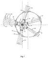
Figure 7 schematically shows a further side view of the embodiment ofFigures 1 to 3 , illustrating the radial distribution of the auger fingers of all subgroups of the auger finger assembly; -
Figures 8 and 9 schematically show a perspective and front view of a three adjacent finger holders similar as in use in the embodiment ofFigures 1 to 3 ; and -
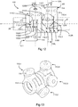
Figures 10 and 11 ; and12 and 13 ; respectively schematically show a front and perspective view of at least three adjacent finger holders according to an alternative embodiment. -
Figure 1 shows a schematic perspective view of an embodiment of arotatable auger assembly 1 for a harvester, such as for example in use in a head or pickup of a combine harvester, a forage harvester, a baler, etc. Theauger assembly 1 comprises a rotatably driventubular auger body 10, of which the contour is only indicated with stripe double dot lines, in order to more clearly shown the elements mounted inside thisauger body 10. Thetubular auger body 10, as shown, is rotatably supported by means ofradial discs tubular auger body 10 to a suitable bearing on a central shaft that allows for the rotation of the auger body around a central rotation axis R along the central axis of theauger body 10. In this way theauger body 10, is rotatably driven along the direction of rotation RD by means of a suitable drive, for suitably conveying the crop during a harvesting operation. It is clear that for example in the case of anauger assembly 1 in use in a grain header of a combine harvester, similar as for example known fromEP1749436 , the crop which is cut from the field is conveyed, transvers to the driving direction of the combine harvester, by means of aleft auger flight 16 andright auger flight 18 that project outwards from the outer surface of thetubular auger body 10, towards a central zone of the header in which a rotatableauger finger assembly 100 is provided, which engages the crop in order to provide for a crop flow generally along the driving direction of the combine harvester from the header towards a further downstream element, such as for example a feeder of the combine harvester. - According to the embodiment shown in
Figure 1 and more clearly shown in the front view of this embodiment inFigure 2 , theauger finger assembly 100 extends axially along the central axis of theauger body 10 along a central zone C in between bothradial discs excenter shaft 20 to which a multiple offingers 120 are individually mounted by means offinger holders 110. Theexcenter shaft 20 is mounted inside the rotatably driventubular auger body 10. It is clear that although theauger body 10 is rotatably driven during the operation of the harvester, theexcenter shaft 20 maintains a stationary position, this means that theexcenter shaft 20 does not rotate around the central rotation axis R of theauger body 10. As shown, theexcenter shaft 20 is mounted parallel and excentric to the central rotation axis R of theauger body 10. As shown more clearly for example inFigures 4 to 6 , theexcenter shaft 20 preferably comprises an elongate shaft with a generally circular cross section. Theexcenter shaft 20 thus extends axially along its central longitudinal excenter axis E parallel to the central rotation axis R of thetubular auger body 10. - In the axial auger finger zone C, there are provided
multiple finger openings 30 that extend through theauger body 10. As will be explained in further detail below, thefinger openings 30 of theauger body 10 are axially and radially distributed along thetubular auger body 10 in order to provide for a suitable distribution of theauger fingers 120 for allowing an optimal crop flow. A corresponding multiple ofauger fingers 120 projects radially from theexcenter shaft 20 through acorresponding finger opening 30 outwards of thetubular auger body 10. As shown, according to this embodiment there are provided thirty-twofinger openings 30 and thirty-twocorresponding auger fingers 120 in the axial auger finger zone C. According to a particular embodiment, in which the width of the axial auger finger zone C and the corresponding axial length of theexcenter shaft 20 is for example approximately 1m, for example in the range of 0,8m to 1,2m, and only allowed for a maximum of twenty-one auger fingers to be arranged by means of prior art finger holders. It is however clear that according to alternative embodiments another suitable number ofauger fingers 120 andcorresponding finger openings 30 could be provided, however in order to increase the crop flow capacity and improve evenness of the crop flow, it is desired to achieve, for the available axial length of theexcenter shaft 20 in the axial auger finger zone C, an as high number ofauger fingers 120 as possible, as this allows to increase the number of axial and radial positions along the tubular auger body which can be provided withauger fingers 120, which increases the forces that can be exerted on the crop flow by the auger finger assembly and improves the uniformity of the distribution of these forces along the different axial and radial locations of therotatable auger body 10 during a harvesting operation. Theauger fingers 120, sometimes also referred to as tines, are elongate elements, such as for example a suitable metal rod, tube, wire, etc. of which the centrallongitudinal axis 120L extends radially with respect to theexcenter shaft 20 as shown inFigure 1 . This means that theauger fingers 120 extend generally along their longitudinal direction in a plane transverse to the longitudinal axial direction E of theexcenter shaft 20, and thus also to the parallel central rotation axis R of theauger body 10. Theauger fingers 120, as shown, extend along theirlongitudinal axis 120L from aninwards end 122 positioned inside theauger body 10, through itscorresponding auger opening 30, to an opposite outwards end 124 outwards of theauger body 10. As further shown, according to this embodiment theauger opening 30 is provided by means of a suitable guide element which provides for a suitably shaped guide surface around theauger opening 30 for guiding theauger finger 120 during its telescopic and pivoting motion relative to thetubular auger body 10 when theauger body 10 is rotatably driven around its rotation axis R, as also shown more clearly inFigures 4 to 6 . Theauger fingers 120 are each individually mounted on theexcenter shaft 120 by means of anauger finger holder 110. As shown theauger fingers 120 are each individually mounted to theexcenter shaft 120 at their inwards 120 by means of acorresponding finger holder 110. It is thus clear that each of theauger fingers 120 extends radially with respect to theexcenter shaft 20 from its inwards end 122 mounted to theexcenter shaft 20 inside thetubular auger body 10, through itscorresponding auger opening 30, to its opposing outwards end 124 outside theauger body 10. It is thus further clear that theauger finger 120, itsfinger holder 110 and itsfinger opening 30 are all provided at the same axial position with respect toexcenter shaft 20. - As shown in
Figures 1 and 2 , the multiple offinger holders 110 of theauger finger assembly 1, each mount theirrespective auger fingers 120 individually on theexcenter shaft 10. This means that there are provided a same multiple ofauger holders 110 as there areavailable auger fingers 120 in the auger finger zone C, which according to the embodiment shown means thirty-twoauger finger holders 110, one for each of the thirty-twoauger fingers 120. As further shown, this multiple offinger holders 110 is mounted adjacent to each other on theexcenter shaft 10. This means that thefinger holders 110 are mounted side by side along the longitudinal direction E of theexcenter shaft 20, or alternatively formulated adjacent to each other along the direction of the rotation axis R. - As further shown in
Figures 1 and 2 , and also more clearly inFigure 3 that shows asubgroup 200 of this embodiment of theauger finger assembly 100 comprising five adjacent finger holders 110.1-110.5, eachfinger holder 110 individually mounts its respective auger finger 120.1-120.5 to theexcenter shaft 20. Asingle finger holder 110 thus mounts asingle auger finger 120 to theexcenter shaft 20. As shown, this embodiment of thefinger holder 110 comprises aradial finger seat 114 that holds the associatedauger finger 120 at itsinwards end 122. Thisradial finger seat 114 projects radially from an axial finger bearing 112 of thefinger holder 110, this means transverse to theexcenter shaft 20 and along a radial direction with respect to the central longitudinal axis E of theexcenter shaft 20. The axial finger bearing 112 of thefinger holder 110 rotatably mounts itsradial finger seat 114 to theexcenter shaft 20. - As shown, the
axial finger bearing 112 has a more or less annular, or tubular shape that encloses theexcenter shaft 20 and thus rotatably mounts theradial finger seat 114 to theexcenter shaft 20, such that it is able to perform a rotary motion in a plane transverse to the central longitudinal axis E of theexcenter shaft 20, and thus also transverse to the parallel central rotation axis R. As most clearly shown in the side views ofFigures 4 to 7 and also in the perspective view ofFigure 9 , the tubular or annular shape of theaxial finger bearing 112 comprises a centralcylindrical opening 111 which encloses the matching circular cross section of theexcenter shaft 20. It is clear that in this way the central longitudinal axis of the centralcylindrical opening 111 is aligned with the central longitudinal axis of theexcenter shaft 20 which it encloses. It is further clear that according to the embodiment shown theaxial finger bearing 112 performs its bearing function with respect to rotation around theexcenter shaft 20 as a plain bearing. In order to reduce friction the finger holder could for example be manufactured from a suitable solid polymer such as for example nylon, polyacetal, polytetrafluoroethylene (PTFE), ultra-high-molecular-weight polyethylene (UHMWPE), rulon, PEEK, urethane, etc. that exhibit low friction with respect to theexcenter shaft 20 which is for example made of a suitable metal such as for example steel. This also allows for a thefinger holder 110 to be manufactured by means of an suitable injection molding process, which allows for an efficient manufacturing process for the desired shape of both thefinger bearing 112 and theradial finger seat 114. Additionally, a suitable amount of play between the centralcylindrical opening 111 and theexcenter shaft 20 could be provided in order to enable an efficient, low wear bearing function. However, it is clear that according to alternative embodiments, theaxial finger bearing 112 could be manufactured in any other suitable way, for example comprising a suitable metal, ceramic, etc. and could perform its bearing function in any other suitable way, for example by means of a suitable ball bearing, roller bearing, bushing, etc. Theradial finger seat 114, which projects radially from theaxial finger bearing 112, this means that theradial finger seat 114 comprises a central longitudinal axis according to a plane transvers to longitudinal axis E of theexcenter shaft 20, also comprises a tubular or annular shape comprising acentral opening 115, which will be more clearly shown with reference to for exampleFigures 8 and 9 , of which the cross section matches that of the cross section of theauger finger 120. According to the embodiment shown inFigure 3 , the radialcentral opening 115 of theradial finger seat 114 encloses the inwards end 122 of theauger finger 120 over adistance 122D along thelongitudinal direction 120L of theauger finger 120. This thus means that theauger finger 120 protrudes into theradial finger seat 114 of itsfinger holder 110 over thisdistance 122D along itslongitudinal axis 120L at itsinwards end 122. As shown, theauger finger 120 can be fixed to itsfinger holder 110 by means of a transverse pin or clips that can be introduced into atransverse bore 126 or opening that passes, transverse to their longitudinal axis, through both theradial finger seat 114 and the introduced inwards end 122 of theauger finger 120 when mounted therein, thereby connecting theauger finger 120 to itsfinger holder 110. Thedistance 122D over which theauger finger 120 protrudes into itsfinger seat 114 of itsfinger holder 110, .is sufficiently long to allow for a secure mounting of the auger finger to thefinger seat 114, for example in the range of 5% to 20% of the overall length of the auger finger 120.1 - As in this embodiment the
auger finger 120 comprises a cross section with a circular outer circumference with anouter radius 120W, the radialcentral opening 115 of theradial finger seat 114 will comprise a mating inner radius which allows insertion of the inwards end 122 of theauger finger 120 along the direction of itslongitudinal axis 120. Theradial finger seat 114, as shown, encloses thiscentral opening 115 by means of a cylindrical,annular collar 113 of which theouter diameter 114W is larger than theouter radius 120W of theauger finger 120. According to this embodiment, the central axis of theannular collar 113 is aligned with the central axis of the radialcentral opening 115. The wall thickness of thisannular collar 113 of the of theradial finger seat 114 that encloses thecentral opening 115 and thus the inserted inwards end 122 of theauger finger 120, is preferably large enough to reliably hold theauger finger 120 even when subjected to an increased load associated with an increased level of crop flow. This means that, along the direction of the rotation axis R, or along the direction of the parallel central longitudinal axis E of theexcenter shaft 20, as clearly shown in for example the view ofFigures 2 ,3 and8 , thewidth 114W of thefinger seat 114 is larger than thewidth 120W of theauger finger 120 and the associatedcentral opening 115 of thefinger seat 114. In the embodiment shown thewidth 114W of the finger seat along the direction of the rotation axis R, or the longitudinal axis E of theexcenter shaft 20, is for example three times thewidth 120W of theauger finger 120. However, it is clear that according to alternative embodiments, any suitable ratio, for example in the range of two times to five times thewidth 120W of theauger finger 120, would provide for asuitable width 114W of thefinger seat 114. Although the annular, cylindrical shape of theradial finger seat 114 is advantageous, as it decreases the chance of stress concentrations at particular locations of thefinger seat 114, other shapes for theradial finger seat 114 are possible as long as its longitudinal axis extends radially with respect to theexcenter shaft 20. Additionally, also the cross section of thecentral opening 115 and the corresponding cross section of theauger finger 120 transvers to itslongitudinal axis 120L could have an alternative shape other than the tubular cross section with a circular outer circumference of the embodiment shown. Alternative shapes for the outer circumference of the cross section could for example be a suitable ellipsoid, a suitable polygon such as for example a suitable triangle, square, rectangle, pentagon, hexagon, etc. or any suitable shape comprising a combination of curves, straight lines and/or angles. Also, when considering these alternative embodiments, it is preferable to ensure a sufficient wall thickness for the material of theradial finger seat 114 that forms thecollar 113 enclosing thecentral opening 115 and the inserted inwards end 122 of thefinger seat 120, and thus, along the direction of the rotation axis R, thewidth 114W of such afinger seat 114 is preferably larger than thewidth 120W of theauger finger 120 as explained above. It is clear that still further alternative embodiments for theauger finger 120, instead of the tubular cross section as shown, theauger finger 120 could for example be embodied as a solid rod comprising a solid cross section. - Although, as shown the
axial finger bearing 112 is formed as a tubular or annular cylindrical element comprising a centralcylindrical opening 111 of which the central axis is aligned with the central axis E of theexcenter shaft 20 when mounted, and which thus encloses theexcenter shaft 20 entirely, alternative embodiments remain possible. As long as theaxial finger bearing 112 at least partly encloses theexcenter shaft 20, such that it is able to perform its bearing function, this means allowing the attachedradial finger seat 114 and itsconnected auger finger 120 to rotate about the central longitudinal axis E of theexcenter shaft 20 in a plane transvers to this central axis E of theexcenter shaft 20 and thus also transverse to the rotation axis of theauger body 10. It should also be clear that, although the embodiment of thefinger holder 110 shown is formed as a unitary element, such as for example a suitably cast, molded or worked plastic or metal element, there are possible alternative embodiments in which the finger holder is formed by means of two or more connected distinct elements. As long as in general, when mounted on theexcenter shaft 20 by means of itsaxial finger bearing 112, thefinger holder 120 comprises aradial finger seat 114 that radially projects from itsaxial finger bearing 112, which means that theradial finger seat 114 is able to hold an associatedauger finger 120 at its inwards end 122 such that itslongitudinal axis 120L projects radially from theexcenter shaft 20, through its correspondingopening 30 in theauger body 10, towards its opposing outwards end 124 outwards of theauger body 10. - It is clear from the views shown in
Figures 2 and3 , and as will be explained in further detail with reference toFigures 8 and 9 , that along the direction of the rotation axis R, and thus also along the direction of the central axis E of theexcenter shaft 20, theradial finger seat 114 of each of thefinger holders 110 at least partly overlaps with thefinger bearing 112 of at least one of itsadjacent finger holders 110. This thus means that, along the direction of the rotation axis R, thewidth 112W of the axial finger bearing 112 of thefinger holder 110, is smaller than thewidth 114W of theradial finger seat 114. As shown, themultiple finger holders 110 are arranged adjacent to each other on theexcenter shaft 20, which means that thefinger holders 110 are arranged in a sequential manner along the longitudinal axis E of theexcenter shaft 20. It is clear from the view shown inFigures 2 and3 , that according to this embodiment, thefinger bearings 112 ofadjacent finger holders 110 are arranged such that they are adjacent to each other on theexcenter shaft 20, thereby forming a sequence of adjacent tubular shaped sections, arranged side by side and enclosing theexcenter shaft 20. When considering for example thesubgroup 200 of this embodiment of theauger finger assembly 100 as shown in more detail inFigure 3 , this means that, with respect to the direction of the rotation axis R, the finger holder 120.2 is positioned in between two adjacent finger holders 120.1 to the left and 120.3 to the right. As shown, with respect to the direction of the rotation axis R, the leftmost outer end of thefinger bearing 112 of finger holder 110.2 is positioned adjacent the opposing rightmost outer end of the adjacent finger holder 110.1, and similarly the rightmost outer end of thefinger bearing 112 of finger holder 110.2 is positioned adjacent the opposing leftmost outer end of it's the other adjacent finger holder 110.3. The same holds for everysubsequent finger holder 110 in this subgroup, this means that finger holder 110.3 is similarly arranged with respect to its adjacent finger holders 110.2 and 110.4, and also finger holder 110.4 is similarly arranged with respect to its adjacent finger holders 110.3 and 110.5. As shown inFigure 3 , for such asubgroup 200 comprising for example fivefinger holders 110 arranged adjacently on theexcenter shaft 20, the total length of theexcenter shaft 20 occupied by thesefinger holders 110 is determined by thewidth 112W of theadjacent finger bearings 112 of the adjacent finger holders 110.1 - 110.5. As shown the length of these five adjacent finger holders 110.1 - 110.5 occupied along theexcenter shaft 20 is equal to or only slightly diverging from five times thewidth 112W of theiraxial finger bearings 112 which are sequentially arranged next to each other along theexcenter shaft 20. It is clear that the same reasoning applies to the entire sequence of the multiple ofadjacent finger holders 110 of theauger finger assembly 100 as shown inFigure 2 , which means that the length of theexcenter shaft 20 occupied by the entire sequence ofadjacent finger holders 110 is determined by thewidth 112W of their respectiveaxial finger bearings 112. It is clear that, in order to allow for such an arrangement the radialauger finger seat 114 of eachfinger holder 110 with alarger width 114W than thewidth 112W of theaxial finger bearing 112, is arranged in such a way that it overlaps with itsadjacent finger holders 110. As the length of theexcenter shaft 20 occupied by the sequence ofadjacent finger holders 110 is determined by thewidth 112W of their sequentially arrangedaxial finger bearings 112 and not by thelarger width 114W of theirradial finger seat 114, this means that the number of sequentially arrangedfinger holders 110 along theexcenter shaft 20 can be maximized without reducing the robustness ofradial finger seat 114. In this way for a predetermined length of theexcenter shaft 20, the number ofauger fingers 120 can be maximized, while still thewidth 120W of theauger finger 120 and thewidth 114W of the correspondingauger finger seat 114 can remain sufficiently large in order to allow for a sufficiently robustauger finger assembly 100. As will be explained in further detail with reference toFigures 4 to 6 , the overlap of theradial finger seat 114 of afinger holder 110 with anadjacent finger holder 110 along the direction of the rotation axis R is possible as theradial finger seats 114 ofadjacent finger holders 110 are positioned at different angular positions with respect to the central longitudinal axis E of theexcenter shaft 20 during the rotational movement of thefinger holders 110 and theirauger fingers 120 around thisexcenter shaft 20 caused by the rotational movement of the rotatably drivenauger body 10. As shown inFigure 3 , for example the longitudinal axis of the auger finger 120.2 and theradial finger seat 114 of its finger holder 110.2 point along a slightly upwards and backwards radial direction with respect to theexcenter shaft 20 according to this front view, this means along the direction indicated with arrow III in the side view ofFigure 4 . Theradial auger seat 114 of the adjacent finger holder 110.1 at the left side and its auger finger 120.1 points along an almost straight line downwards. Theradial auger seat 114 of the other adjacent finger holder 110.3 at its opposing right side and its auger finger 120.3 point along a slightly upwards and forwards radial direction with respect to theexcenter shaft 20. It is clear that in this way, although theradial auger seat 114 of the auger finger holder 120.2, according to this embodiment overlaps with both its adjacent auger finger holders 120.1 and 120.3 along the direction of the rotation axis R, there is no risk for interference with theradial auger seats 114 of these adjacent auger finger holders 120.1 and 120.3, as they are positioned at a different radial position with respect to theexcenter shaft 20. - As shown in
Figure 3 , and further shown in more detail inFigure 8 , according to this embodiment of theauger finger holder 110, along the direction of the rotation axis R or the longitudinal axis E of theexcenter shaft 20, theradial finger seat 114 overlaps at both sides whereadjacent finger holders 110 are provided over a portion of itswidth 114W that is indicated asoverlap distance 1140. According to this embodiment, as shown theoverlap distance 1140 is approaching half of the difference between thelarger width 114W of theradial finger seat 114 and thewidth 112W of theaxial finger bearing 112. It is clear that thisoverlap distance 1140 ensures that, along the direction of the rotation axis R or the direction of the longitudinal axis E of theexcenter shaft 20, for each of thefinger holders 110, thedistance 120D between the centrallongitudinal axes 120L of itsfinger 120 and thefinger 120 of itsadjacent finger holders 110, is smaller than thewidth 114W of itsfinger seat 114. It is clear that thedistance 120D along the rotation axis R betweenadjacent fingers 120 is the same as the distance between the centrallongitudinal axes 120L ofadjacent auger fingers 120 along the direction of the longitudinal axis E of theexcenter shaft 20. It is further clear that, as the centrallongitudinal axes 120L of theseauger fingers 120 project radially from theexcenter shaft 20, this corresponds to the minimum distance between the centrallongitudinal axes 120L ofadjacent fingers 120 which is reached at the level of the longitudinal axis E of theexcenter shaft 20. According to the embodiment shown thisdistance 120L will be approaching thewidth 112W ofaxial auger bearing 112, as it is largely determined by two times half of thewidth 112W, this means half of thewidth 112W of each of bothaxial auger bearings 112 of twoadjacent finger holders 110. According to the embodiment shown thewidth 112W of the axial auger bearing 112 of thefinger holder 120 is for example 70% of thewidth 114W of itsradial finger seat 114, and as shown, thedistance 120D along the direction of the longitudinal axis E of theexcenter shaft 20 between theauger fingers 120 ofadjacent finger holders 110 is also for example 70% of thewidth 114W of their radial finger seats 114. According to this embodiment, such as most clearly shown inFigure 8 , this means that theoverlap distance 1140 along the direction of the longitudinal axis E of theexcenter shaft 20 is for example 15% of thewidth 114W of theradial finger seat 114 at its left side and approximately the same at its opposing right side, for example 15% of thewidth 114W of theradial finger seat 114. According to the embodiment, both overlapdistances 1140 of theradial finger seat 114 are equal and total up to 30% of thewidth 114W of theradial finger seat 114. It is clear that this is the complement of thewidth 112W of the axial finger bearing which is 70% of thewidth 114W of theradial finger seat 114 along the direction of the rotation axis R. It is clear that in this way the maximum number ofadjacent finger holders 110 that can be arranged side by side on theexcenter shaft 20, which is determined by thewidth 112W of theaxial finger bearing 112 can be increased. When for example thewidth 112W of theaxial finger bearing 112 is 70% of thewidth 114W of theradial finger seat 114, which thus means a reduction of 30% of the width along the direction of the rotation axis R. It is clear that this will result in an increase of the maximum number ofadjacent finger holders 110 on anexcenter shaft 20 with a predetermined length, when compared to prior art individual finger holders in which there was no overlap ofadjacent finger holders 110. In the embodiment described above in which thirty-twoadjacent finger holders 110 are provided on theexcenter shaft 20 with a length of about 1m in a central zone C, and where thewidth 112W of theaxial finger bearing 112 is 70% of thewidth 114W of theradial finger seat 114, this means that for pior art finger holders with the same width for the radial finger seat only a maximum of twenty-two adjacent finger holders would have been possible without the overlap described above being present. - It is further clear that according to alternative embodiments, along the direction of the longitudinal axis E of the
excenter shaft 20, other ratios then the 70% described above are possible for the ratio of thewidth 112W of the axial finger bearing 112 with respect to thewidth 114W of theradial finger seat 114, which according to this embodiment also determines the ratio between the centrallongitudinal axes 120L ofadjacent fingers 120 and thewidth 114W of theradial finger seat 114. A suitable ratio in general results in the fact that along the direction of the rotation axis R, for each of thefinger holders 110, thedistance 120D between the centrallongitudinal axes 120L of itsfinger 120 and thefinger 120 of at least one of itsadjacent finger holders 110, is smaller than thewidth 114W of itsfinger seat 114. Preferably such a suitable ratio allows for a sufficient level of overlap so that a sufficient increase of the number finger holders can be achieved with respect to prior art finger holders, which will often result in a ratio of less than 90% for the ratio of thewidth 112W of the axial finger bearing 112 with respect to thewidth 114W of theradial finger seat 114. According to the embodiment described above, the latter thus resulting, for eachfinger holder 110, inoverlap distances 1140 totaling at least 10% of thewidth 114W of theirradial finger seat 114. It is clear that in general any suitable ratio that, for each of thefinger holders 110 of theauger finger assembly 110, when theauger fingers 120 are mounted, leads to thedistance 120D between the centrallongitudinal axes 120L of itsfinger 120 and thefinger 120 of at least one of itsadjacent finger holders 110 is less than 90%. Preferably, a suitable ratio of thewidth 112W of the axial finger bearing 112 with respect to thewidth 114W of theradial finger seat 114 of thefinger holder 110, also insures that theaxial finger bearing 112 remains sufficiently wide along the direction of the longitudinal axis E of theexcenter shaft 20 in order to reliably cope with the forces transferred from theauger finger 120 via theradial finger seat 114 and theaxial finger bearing 112 to theexcenter shaft 20, and is for example in the range of 20% to 80%. It is clear that such a ratio according to the embodiment of theauger finger assembly 100 described above will in general result in thedistance 120D, between the centrallongitudinal axes 120L of thefingers 120 ofadjacent finger holders 110, being in the range of 20% to 80% of thewidth 114W of thefinger seat 114 of thefinger holders 110. - It is further clear, from what was described above with reference to the embodiment of the
auger finger assembly 100 as shown inFigures 1 to 9 , that thefinger holder 110 has a mirror symmetrical shape with respect to the plane orthogonal to the central longitudinal axis E of theexcenter shaft 20 and along thelongitudinal axis 120L of itsauger finger 120 when mounted, such as clearly shown in the views ofFigures 3 and8 . Additionally, as allfinger holders 110 have an identical shape, which simplifies manufacturing and assembly of theauger finger assembly 100, it is clear that thedistance 120L from the central longitudinal axis of aparticular auger finger 120 to the longitudinal axes of itsadjacent auger fingers 120 will be identical. For example thedistance 120D from the centrallongitudinal axis 120L of auger finger 120.4 of the finger holder 110.4 to the centrallongitudinal axis 120L of its adjacent auger finger 120.5 of its adjacent finger holder 110.5 at its right side according to the view shown inFigures 2 and3 , is identical to thedistance 120L to the centrallongitudinal axis 120L of its other adjacent auger finger 120.3 of the other adjacent finger holder 110.3 at its opposite left side according to the view shown inFigures 2 and3 . This thus means that, along the direction of the longitudinal axis E of theexcenter shaft 20, the mean distance 120MD between theselongitudinal axes 120L of these adjacent auger fingers 120.3, 120.4 and 120.5 will be equal to thedistance 120D, as shown inFigure 3 . Additionally it is clear that this also holds for theother finger holders 110 of theauger finger assembly 100 which, along the direction of the rotation axis R, are provided at opposing sides withadjacent finger holders 110. From what is described above, with reference to thedistance 120D between thelongitudinal axes 120L ofadjacent auger fingers 120 ofadjacent finger holders 110, it is clear that for the embodiment of theauger finger assembly 100 the overlappingfinger holders 110 shown inFigures 1 to 9 are arranged such that also the mean distance 120MD between the centrallongitudinal axes 120L of theadjacent fingers 120 ofadjacent finger holders 110, is smaller than thewidth 114W of thefinger seat 114, thereby allowing for an increase in the number offinger holders 110 arranged adjacently on theexcenter shaft 20 combined with a high level of robustness of thefinger holder 110 as there is no corresponding reduction of thewidth 114W of thefinger seat 114. Preferably, as explained above this mean distance 120MD is less than 90%, for example in the range of 20% to 80%, of thewidth 114W of thefinger seat 114, in order to allow for a sufficient increase of the number offinger holders 110, but still retaining a sufficientlylarge width 112W along the direction of the longitudinal axis E of theexcenter shaft 20 for theaxial finger bearing 112. According to the exemplary embodiment described above with reference toFigure 3 , there is provided a mean distance 120MD of for example 70% of thewidth 114W of thefinger seat 114 ofadjacent finger holders 110. - It is further clear that according to the embodiment shown in
Figures 1 - 9 , along the direction of the rotation axis R, theradial finger seat 114 of each of thefinger holders 110 that comprises twoadjacent finger holders 110, at least partly overlaps with thefinger bearing 112 of both of itsadjacent finger holders 110. It is clear that, for example, the radial finger seat 114.2 of finger holder 110.2 overlaps along the direction of the rotation axis R and thus also along the direction of the longitudinal axis E of theexcenter shaft 20, with the finger bearing 112.1 of the finger holder 110.1 at its left side in the view ofFigure 3 , and also overlaps, along the direction of the rotation axis R, with the finger bearing 112.3 of the finger holder 110.3 at the opposing right side in the view ofFigure 3 . Additionally, for example, the radial finger seat 114.3 of the finger holder 110.3 overlaps at both opposing sides along the direction of the longitudinal axis E of the excenter shaft, with respectively the finger bearing 112.2 of the finger holder 110.2 and the finger bearing 112.4 of the finger holder 110.4. Similarly the radial finger seat 114.4 overlaps at both opposing sides along the direction of the longitudinal axis E of theexcenter shaft 20 with the axial finger bearing 112.3 and 112.5. It is clear that similarly all otherradial finger seats 114 offinger holders 110 that comprise twoadjacent finger holders 110 at both opposing sides along the direction of thelongitudinal excenter shaft 20, overlap with theaxial finger bearings 112 of these twoadjacent finger holders 110 similar as described above. - Alternative embodiments of the
finger holder 110, similar to that shown inFigures 1 - 9 , are possible, which are not mirror symmetrical with respect to the plane orthogonal to the central longitudinal axis E of theexcenter shaft 20 and along thelongitudinal axis 120L of itsauger finger 120 when mounted, such that this no longer results in an equal share of theoverall overlap distances 1140 at both opposing sides of thefinger holder 110 with respect to the direction of the rotation axis R, but in a differing share of theoverall overlap distance 1140 at both opposing sides of thefinger holder 110. The share of theoverlap distance 1140 at one side could for example be in the range of 10% to 90% of the overlap distance at the opposing side of thefinger holder 110 with respect to the longitudinal axis E of theexcenter shaft 20. However, similar as for the embodiment described above with reference toFigures 1 to 9 , also for thesefinger holders 110, along the direction of the rotation axis R, thewidth 112W of theaxial finger bearing 112 is smaller than thewidth 114W of theradial finger seat 114. - As shown, according to the embodiment of
Figures 1 - 9 , the axial finger bearing 112 of therespective finger holders 110 extends along the direction of the rotation axis R, or equally in the direction of the central longitudinal axis E of theexcenter shaft 20, between twoouter ends Figure 3 a firstouter end 112L is situated at the leftmost side of theaxial finger bearing 112, while an opposing secondouter end 112R is situated at the rightmost side of theaxial finger bearing 112 according to this view. As further shown, it is clear that thewidth 112W of theaxial finger bearings 112 is the distance between their respective outer ends 112L, 112R. As further shown, also theradial finger seat 114 of therespective finger holders 110 extends along the direction of the rotation axis R, between twoouter ends Figure 3 , according to this view in which the rotation axis R extends from left to right, a firstouter end 114L is located at the leftmost end of theradial finger seat 114, while an opposing secondouter end 114R is located at the rightmost end of theradial finger seat 114. Thewidth 114W of theradial finger seat 114 along the direction of the rotation axis R, or the direction of the longitudinal axis E of the excenter shaft, as shown, thus being the distance between these outer ends 114L, 114R. It is further clear, that, along the direction of the rotation axis R, for example, theouter end 112R of the axial finger bearing 112.4 of the finger holder 112.4 is positioned in between the outer ends 114L, 114R of the radial finger seat 114.5 of the overlapping adjacent finger holder 110.5. Also, the otherouter end 112L of the axial finger bearing 112.4 of this finger holder 110.4, will similarly be positioned in between the outer ends 114L, 114R of the radial finger seat 114.3 of the other overlapping adjacent finger holder 110.3. As shown, according to this embodiment, for each of thefinger holders 110 that has two respective, overlappingadjacent finger holders 110, both of the outer ends 112L, 112R of the axial finger bearing 112 of thisfinger holder 110 are respectively is positioned in between the outer ends 114L, 114R of thefinger seat 114 of the respective, overlappingadjacent finger holder 110 along the direction of the longitudinal axis E of theexcenter shaft 20 or the rotation axis R. -
Figure 8 shows an embodiment of anauger finger assembly 100 comprising theexcenter shaft 20 and threeadjacent finger holders 110, sequentially arranged on theexenter shaft 20 along the direction of the longitudinal axis E of theexcenter shaft 20. It is clear that inFigure 8 only threeadjacent finger holders 110 are shown in order to more clearly show the sequential arrangement of the individual,adjacent finger holders 110, and that any suitable multiple ofadjacent finger holders 110 could be arranged along theexcenter shaft 20. As described with reference toFigures 1 to 3 , theauger assembly 100 could further also comprise thetubular auger body 10 comprising the corresponding multiple ofopenings 30 for the multiple ofauger fingers 120 of the multiple offinger holders 110. The multipleadjacent finger holders 110 are then arranged individually on theexcenter shaft 20 such that the corresponding multiple ofauger fingers 120 can be mounted as explained in detail above. In this way each of theauger fingers 120 extends from itsinwards end 122, that is held at theradial finger seat 114 of its associatedfinger holder 110, along itslongitudinal axis 120L through its associatedopening 30 in thetubular auger body 10, to itsoutward end 124.Figure 9 shows four of thefinger holders 110 for use in the embodiment of theauger finger assembly 100 ofFigure 8 . Although there are shown four any other suitable multiple offinger holders 110 is possible. It is clear that, whensuch finger holders 110 are mounted adjacent to each other on theexcenter shaft 10, as shown inFigure 8 , along the direction of the rotation axis R or the direction of the longitudinal axis E of the excenter shaft, such that theradial finger seat 114 of thefinger holders 110 at least partly overlaps with thefinger bearing 112 of at least one of itsadjacent finger holders 110 as explained above a larger number of individual finger holders can be arranged along a predetermined length of theexcenter shaft 20, without compromising the flexibility for arranging the individual auger fingers and the robustness of the finger holder. - It is further also clearly shown in
Figures 8 and 9 , that the axial finger bearing 112 of thefinger holders 110 retains itswidth 112W up to afirst radial distance 112D with respect to the longitudinal axis E of the excenter shaft. As already mentioned above, according to the embodiment shown, the tubular or annularaxial finger bearing 112 comprises acentral opening 111 with a radius that approximates theradius 20D of theexcenter shaft 20 and a radialannular wall thickness 112T, so that thefirst radial distance 112D approximates theradius 20D of theexcenter shaft 20 increased with the radialannular wall thickness 112T. Thefirst radial distance 112D to the longitudinal axis E of theexcenter shaft 20, is thus larger than the radius of theexcenter shaft 20D. As shown, in a first radial zone, in between theexcenter shaft 20 and thisfirst radial distance 112D, thewidth 112W of the axial finger bearing 112 of theauger finger 110 remains smaller than thewidth 114W of theradial finger seat 114 along the direction of the longitudinal axis E of theexcenter shaft 20 as explained in more detail above. As shown it is only at a second radial zone, which extends outwardly from asecond radial distance 114D with respect to the longitudinal axis E of theexcenter shaft 20. This secondradial distance 114D, which, as shown, is larger than thefirst radial distance 112D, forms a lower limit for the second radial zone in which theradial finger seat 114 is allowed to stretch out along the direction of the longitudinal axis E of theexcenter shaft 20 beyond thewidth 112W of theaxial finger bearing 112 to thewidth 114W of theradial finger seat 114 which is preferably reached at the location where theauger finger 120 is mounted in order to allow for a robust mounting of theauger finger 120 to thefinger holder 110. As shown in the embodiment in between the first radial zone and the second radial zone preferably the width is increased in a suitable and gradual way from thewidth 112W of theaxial finger bearing 112 to thewidth 114W of theradial finger seat 114 as in this way the risk of stress concentrations is reduced. However, it is clear that alternative embodiments are possible, and for example also embodiments in which the increase from thewidth 112W to thewidth 114W is performed in a stepwise fashion. - It is further clear, from for example
Figures 8 and 9 , whenfinger holders 110 according to this embodiment are arranged adjacent to each other on theexcenter shaft 20, by inserting theexcenter shaft 20 into their centralcylindrical opening 111 of theiraxial finger bearing 112, each of thefinger holders 110 is positioned in an angular position with respect to the central longitudinal axis E of the excenter shaft, such that itsradial finger seat 114 does not interfere with the angular position of the adjacentradial finger seats 114 of theadjacent finger holders 110 with which itsradial finger seat 114 overlaps along the direction of the central longitudinal axis E of theexcenter shaft 20. It is clear that, also during the operation of thefinger assembly 100, in which, with respect to the central longitudinal axis E of theexcenter shaft 20, the angular positions ofadjacent finger holders 110 relative to each other vary to a predetermined degree, during a revolution of theauger body 10 around its rotation axis R and the corresponding revolution of theauger finger holders 110 around theexcenter shaft 20, interference of theradial finger seats 114 of overlappingfinger holders 110 is to be avoided. According to the embodiment of theauger assembly 100 shown inFigures 1 to 7 , during the operation of theauger assembly 100 there must be provided a minimal relative difference in the respective angular positions of theradial finger seats 114 of adjacent overlappingauger fingers 110 relative to each other in the range of 50° to 80°, for example 60° or 75°. -
Figures 4 to 5 show the angular positions, with respect to the central axis E of theexcenter shaft 20, of the five adjacent finger holders 110.1-110.5 of thesubgroup 200 shown inFigure 3 of the embodiment of theauger finger assembly 100 as shown inFigures 1 and 2 , during an operation of theauger finger assembly 100 in which theauger body 10 is rotated along the rotation direction RD around its rotation axis R.Figures 4 to 5 shown theauger body 10 in different angular positions with respect to the rotation axis R during its rotational movement around this rotation axis R. As shown, thecorresponding finger openings 30 of the five auger fingers 120.1-120.5 mounted to theexcenter shaf 20 by the five finger holders 110.1-110.5 of thesubgroup 200 are distributed around the circumference of theauger body 10. This means that the angular positions of these fivefinger openings 30 with respect to the rotation axis R of theauger body 10 approximate an even angular distribution. As shown in the view ofFigures 4 to 6 , the fivefinger openings 30 of this subgroup are distributed around the circumference of theauger body 10 such that, with respect to the rotation axis R, the angle between angularlyadjacent finger openings 30 approximate one fifth of 360°, for example with a maximum deviation of 20%. It is clear that such a distribution is preferable as in this way the auger fingers 120.1 - 120.5 can distribute their crop engaging function as uniformly as possible with respect to the circumference of theauger body 10. It is further clear that the angular distribution of thefinger openings 30 on the circumference of theauger body 10 around the rotation axis R determines the angular distribution of the corresponding auger fingers 120.1 - 120.5 and theirfinger holders 110 around the central axis E of theexcenter shaft 20. As shown inFigures 4 to 6 , although, during operation of theauger finger assembly 100 the angle between the adjacent angular positions of thefinger openings 30 remains constant with respect to the rotation axis R, the angle between the angular positions of the corresponding angularly adjacent auger fingers 120.1 - 120.5 and their finger holders 110.1 - 110.5 with respect to the rotation axis E of theexcenter shaft 20 varies during the rotation of theauger body 10. According to this embodiment, in whichfinger holders 110 overlap with both axiallyadjacent finger holders 110, this means that adjacent along the direction of the central axis E of theexcenter shaft 20, in order to provide for a sufficient difference in angular positions of these axiallyadjacent finger holders 110 such that a suitable arrangement without interference of their overlapping radial finger seats 114 is obtained during the operation of theauger finger assembly 100, are provided withfinger openings 30 that are not in an angularly adjacent position. For example, this means that, as viewed inFigures 4 to 6 , with reference to the angular position of thefinger opening 30 of the corresponding auger finger 120.3 and corresponding finger holder 110.3, the angular positions of bothfinger openings 30 of both its axially adjacent auger fingers 120.2 and 120.4 and their corresponding fingers holders 110.2 and 110.4, with which the finger holder 110.3 overlaps, are not angularly adjacent with respect to the rotation axis R. This means that bothfinger openings 30, which are in an angular adjacent position to thefinger openings 30 with respect to the rotation axis R, are axially positioned on theauger body 10 for cooperation withcorresponding auger fingers 120 of which thefinger holders 110 don't overlap. According to this embodiment this for example means that the angularlyadjacent openings 30 of that auger finger 120.3 and finger holder 110.3, are axially positioned on theauger body 10 to respectively cooperate with the auger fingers 120.1 and 120.5, and their finger holders 110.1 and 110.5. It is clear that the finger holder 110.3 does not overlap with these finger holders 110.1 and 110.5. It is further clear that the finger holder 110.3 is also not axially adjacent to these finger holders 110.1 and 110.5. It is further clear that the same reasoning could be applied for the arrangement of the auger fingers 120.1 to 120.5, the axial sequential arrangement of their corresponding finger holders 110.1 - 110.5 and the angular arrangement of theircorresponding finger openings 30. Such an arrangement is preferable as in this way a sufficiently large angle between the angular positions of overlappingfinger holders 110 is obtained during the operation of theauger finger assembly 100 in which theauger body 10 rotates around the rotation axis R. Additionally, it is clear that according to this embodiment theauger finger assembly 100 comprises a plurality of sequentially arrangedsubgroups 200 comprising a set of fiveadjacent finger holders 110,auger fingers 120 andcorresponding finger openings 30 similarly arranged as described above. According to alternative embodiments, thesesubgroups 200 could comprise any other suitable number ofadjacent finger holders 110, such as for example four, six, seven, eight, nine or more. A sufficiently high uneven number is however preferable, such as for example five, seven, nine, etc. as in this way a sufficiently uniform distribution of the impact of the auger fingers on the crop material along the circumference of the auger body can be achieved and the uneven number of auger fingers in such asubgroup 200 facilitates the arrangement of thefinger openings 30 for corresponding finger holders that overlap with both axially adjacent finger holders, as then there can be composed a simple sequential arrangement of the axial finger holders along theexcenter shaft 20 by providing an axial sequence in which, with respect to the angular position for a corresponding auger finger, the next auger finger in the sequence and its corresponding finger opening are provided with an angular positon which is not angularly adjacent. According to the embodiment shown inFigures 4 to 6 , this means that in the axial sequence of thesubgroup 200, that comprises an axial sequence of adjacent auger fingers 120.1, 120.2, 120.3, 120.4 and 120.5, corresponds to an angular sequence around the circumference of theauger body 10 along the direction of rotation RD of angularly adjacent auger fingers 120.3, 120.1, 120.4, 120.2, 120.5. This angular sequence could be viewed as a sequence in which in between each axially adjacent auger finger and corresponding finger holder there is interposed an auger finger and corresponding finger holder which is not axially adjacent to both, for example in between the axially adjacent auger fingers 120.3 and 120.4, there is interposed in the angular sequence the auger finger 120.1, which is not axially adjacent to both these auger fingers 120.3 and 120.4; in between auger finger 120.1 and 120.2 similarly 120.4 is interposed in the angular sequence, etc. - In addition, as clearly shown in
Figure 7 , the distribution along the circumference of theauger body 10, according to the embodiment of the auger finger assembly ofFigures 1 - 9 , which comprises a plurality ofadjacent subgroups 200 is still further optimized. As shown inFigures 1 to 6 , eachsubgroup 200 of the auger assembly comprises a subset of fiveadjacent finger holders 110 of which the associatedauger fingers 120 andopenings 30 are distributed angularly along a single revolution of the circumference of theauger body 10 similarly as described above. As further shown inFigures 1 to 3 and most clearly in the side view along the direction of the rotation axis inFigure 7 , the angular positions of therespective auger fingers 120 andopenings 30 ofdifferent subgroups 200 differ from each other. As shown the angular positions of the corresponding auger fingers ofdifferent subgroups 200 differ from each other in some kind of a wavy pattern within a range of for example 10° - 15°, which optimizes the uniformity of the crop flow. However it is clear that alternative embodiments are possible, for example in which more random variations in the angular position between the respective auger fingers ofdifferent subgroups 200 are present. Such an increase in the variation of the angular position of theauger fingers 120 of theauger finger assembly 100 is further also advantageous, as it improves the distribution of the loads imparted by therespective auger fingers 120 via theircorresponding finger holders 110 on theexcenter shaft 20 during operation of theauger finger assembly 100. It is clear that, for an embodiment of anauger finger assembly 100 in which all augerfingers 120 are positioned in an angularly aligned way, this means at a plurality of aligned angular positions, this will result in a corresponding plurality of peak loads on theexcenter shaft 20 for each revolution of theauger body 10, as the loads exerted by the crop on each set of angularly aligned auger fingers will be imparted in a synchronized way. It is clear that, by the additional variation of the angular position of theauger fingers 120 as described above, the loads will be exerted by the crop on the different auger fingers in a less synchronized way, leading to lower and wider peaks of the loads exerted by the auger fingers via their auger finger holders on the excenter shaft during one revolution of the auger body. Additionally, it is also clear that the individual mounting of theauger fingers 120 by theirfinger holders 110 on theexcenter shaft 20, still further optimizes distribution of these loads, as the loads of these individually mountedauger fingers 120 are then also spread even better along the direction of the longitudinal central axis E of theexcenter shaft 20. - It is further clear that, as already mentioned above, as shown in
Figures 1 and 2 , and also more clearly inFigure 3 which shows asubgroup 200 of this embodiment of theauger finger assembly 100, eachfinger holder 110 individually mounts its respective auger finger 120.1-120.5 to theexcenter shaft 20. Asingle finger holder 110 thus mounts asingle auger finger 120 to theexcenter shaft 20. As further shown, according to this embodiment of thefinger holder 110, it comprises aradial finger seat 114 that holds the associatedauger finger 120 at itsinwards end 122. Thisradial finger seat 114 projects radially from an axial finger bearing 112 of thefinger holder 110, this means transverse to theexcenter shaft 20 and along a radial direction with respect to the central longitudinal axis E of theexcenter shaft 20. The axial finger bearing 112 of thefinger holder 110 rotatably mounts itsradial finger seat 114 to theexcenter shaft 20, such that the associatedauger finger 120 can be rotated by means of the associatedfinger opening 20 in theauger body 10 around theexcenter shaft 20 during operation of theauger finger assembly 100. - It is clear that still further alternative embodiments are possible to the embodiment described above in which a
finger holder 110 generally overlaps with both itsadjacent finger holders 110. Alternative embodiments are possible, in which in general, along the direction of the rotation axis R, theradial finger seat 114 of each of thefinger holders 110 that comprises twoadjacent finger holders 110, at least partly overlaps with thefinger bearing 112 of one of itsadjacent finger holders 110. One such alternative embodiment is shown inFigures 10 and 11 , a further one is shown inFigures 12 and 13 . The embodiment shown inFigures 10 and 11 is similar to the embodiment ofFigures 1 to 9 , and similar elements have been provided with the same reference sign and generally function as explained above. However, thelongitudinal axis 120L of theauger finger 120, which still forms an axis of symmetry for theradial finger seat 114 but no longer for theaxial finger bearing 112 which now comprises an axis of symmetry, which is shifted along the longitudinal axis E of theexcenter shaft 20 with respect to the axis of symmetry of theradial finger seat 114. In this way, as shown along the direction of the rotation axis R, only one of the outer ends 112L or 112R of theaxial finger bearing 112 is positioned in between the outer ends 114L, 114R of thefinger seat 114 of a respective, overlappingadjacent finger holder 110. According to this embodiment, the other outer end of the axial finger bearing is in line with the respective outer end of the finger seat of its finger holder. This embodiment offers next the advantage that the reduced width of theaxial finger bearing 112 allows for an increase in the number offinger holders 10 that can be arranged along a given length of theexcenter shaft 20 as thedistance 120D between the longitudinal axes of the auger fingers of overlappingadjacent finger holders 110 is reduced, which thus also reduces the relatedmean distance 120D for the auger finger assembly, additionally the advantage that there is only pairwise overlap of thefinger holders 110. This means that a large degree of freedom is available for choosing the angular position for the finger holders that do not overlap, as there is no risk of interference of their respective radial auger seats 114. As shown theoverlap distance 1140 according to this embodiment is for example about 30% of thewidth 114W of theradial finger seat 114. It is clear that another ratio for the overlap distance could be chosen but preferably it stays below 50% of thewidth 114W of theradial finger seat 114 as thelongitudinal axis 120L of theauger finger 120 is offset with respect to the axis of symmetry of the axial finger bearing 112 of itscorresponding finger holder 110 and in this way during operation induced moments resulting from the load on the auger finger and resulting from the offset position of theradial finger seat 114 with respect to theaxial finger bearing 112 are kept within acceptable limits. - The further alternative embodiment of
Figures 12 and 13 shows an embodiment of the auger finger assembly withfinger holders 110 of which the radial finger seat is generally similar to that described with reference to the embodiments mentioned above and similar elements are referenced with similar elements and generally function in a similar way. The main difference with the embodiments mentioned above is that theaxial finger bearing 112 along the direction of the rotation axis R comprises two axial bearing sections 116.1 and 116.2 with anaxial opening 118 in between. As shown, along the direction of the rotation axis R, the axial finger bearing 112 sequentially comprises: a first axial bearing section 116.1 extending from its firstouter end 112L to a firstintermediate end 118L; subsequently anaxial opening 118 extending between the firstintermediate end 118L to a secondintermediate end 118R; and finally a second axial bearing section 116.2 extending from the secondintermediate end 118R to its secondouter end 112R. As shown, thewidth 118W of theaxial opening 118 is slightly larger than thewidth 116W of the first or second axial bearing section 116.1, 116.2. This allows axially adjacent finger holders to overlap in a pairwise fashion by positioning in theaxial opening 118 respectively the first or second axial bearing section 116.1, 116.2 of a respective, overlappingadjacent finger holder 110. In this way, even when according to the embodiment as shown, the width of the axial finger bearing 112 of thefinger holders 110 equals thewidth 114W of itsradial finger seat 114, there is provided for anoverlap distance 1140 equal to the sum of the width of theaxial opening 118W and thewidth 116W of one of the axial bearing sections 116.1 or 116.2. As shown theoverlap distance 1140 could be for example two thirds of the width of theradial finger seat 114W. It is clear that according to alternative embodiments theoverlap distance 1140 could have other such ratios such as for example in the range of 50% to 85%. However in other embodiments therespective width 116W of the axial bearing sections 116.1 and 116.2 is equal to or only slightly smaller than thewidth 118W of theaxial opening 118, which thus means that thesewidths width 114W of theradial finger seat 114, as in this way, as shown inFigures 10 and 11 a mirror symmetrical construction of the axial finger bearing 112 with respect to thelongitudinal axis 120L of theauger finger 120 when mounted is realized, thereby providing for a robust construction in which thewidth 116W of the axial bearing sections is maximized. - It is clear that still further alternative embodiments or combinations of embodiments of the finger holders and of the auger finger assembly then those described above, as long as in general along the direction of the rotation axis R, which also means along the direction of the longitudinal axis E of the
excenter shaft 20, theradial finger seat 114 of each of thefinger holders 110 at least partly overlaps with the axial finger bearing 112 of at least one of itsadjacent finger holders 110.
Claims (15)
- An auger finger assembly (100) comprising:- an excenter shaft (20) configured to be mounted inside a rotatably driven tubular auger body (10) and comprising a central longitudinal axis (E) parallel and excentric to a central rotation axis (R) of the auger body (10);- a multiple of finger holders (110) mounted adjacent to each other on the excenter shaft (20) along the direction of the rotation axis (R) and each configured to individually mount an auger finger (120), each finger holder (110) comprising:CHARACTERISED IN THAT,- an axial finger bearing (112) at least partly enclosing the excenter shaft (20); and- a radial finger seat (114) radially projecting from the axial finger bearing (112) and configured to hold an associated auger finger (120) extending along a central longitudinal axis (120L) at an inwards end (122),
along the direction of the rotation axis (R), the radial finger seat (114) of each of the finger holders (110) at least partly overlaps with the axial finger bearing (112) of at least one of its adjacent finger holders (110). - An auger finger assembly according to claim 1, characterized in that, along the direction of the rotation axis (R), for each of the finger holders (110), the distance (120D) between the central longitudinal axes (120L) of its finger (120) and the finger (120) of at least one of its adjacent finger holders (110), is smaller than the width (114W) of its finger seat (114).
- An auger finger assembly according to claim 2, characterized in that the distance (120D) between the central longitudinal axes (120L) of its finger (120) and the finger (120) of at least one of its adjacent finger holders (110) is less than 90%, for example in the range of 20% to 80%, of the width (114W) of its finger seat (114).
- An auger finger assembly according to any of the claims 1 to 3, characterized in that along the direction of the rotation axis (R), the mean distance (120MD) between the central longitudinal axes (120L) of the adjacent fingers (120) of adjacent finger holders (110), is smaller than the width (114W) of their finger seat (114).
- An auger finger assembly according to claim 4, characterized in that this mean distance (120MD) is less than 90%, for example in the range of 20% to 80%, of the width (114W) of their finger seat (114).
- An auger finger assembly according any of the preceding claims, characterized in that along the direction of the rotation axis (R), the radial finger seat (114) of each of the finger holders (110) that comprises two adjacent finger holders (110), at least partly overlaps with the finger bearing (112) of one of its adjacent finger holders (110).
- An auger finger assembly according any of the claims 1 to 5, characterized in that along the direction of the rotation axis (R), the radial finger seat (114) of each of the finger holders (110) that comprises two adjacent finger holders (110), at least partly overlaps with the finger bearing (112) of both of its adjacent finger holders (110).
- An auger finger assembly according to any of the preceding claims, characterized in that, each of the finger holders (110) is configured such that, along the direction of the rotation axis (R), the width (112W) of the axial finger bearing (112) is smaller than the width (114W) of the radial finger seat (114).
- An auger finger assembly according to any of the preceding claims, characterized in that, the finger holders (110) are configured such that along the direction of the rotation axis (R):- the axial finger bearing (112) extends between two outer ends (112L, 112R), the width (112W) of said axial finger bearing (112) being the distance between said outer ends (112L, 112R); and- the radial finger seat (114) extends between two outer ends (114L, 114R), the width (114W) of said radial finger seat (114) being the distance between said outer ends (114L, 114R); and- at least one of the outer ends (112L, 112R) of the axial finger bearing (112) is positioned in between the outer ends (114L, 114R) of the finger seat (114) of a respective, overlapping adjacent finger holder (110).
- An auger finger assembly according to claim 9, characterized in that the finger holders (110) are configured such that along to the direction of the rotation axis (R):- the axial finger bearing (112) sequentially comprises:- A first axial bearing section (116.1) extending from its first outer end (112L) to a first intermediate end (118L);- An axial opening (118) extending between the first intermediate end (118L) to a second intermediate end (118R); and- A second axial bearing section (116.2) extending from the second intermediate end (118R) to its second outer end (112R)- the width (118W) of the axial opening (118) being equal to or larger than the width of the first or second axial bearing section (116.1, 116.2); and- in the axial opening (118) there is positioned the first or second axial bearing section (116.1, 116.2) of a respective, overlapping adjacent finger holder (110).
- An auger finger assembly according to any of the preceding claims, characterized in that the auger finger assembly further comprises:- a tubular auger body (10) comprising a corresponding multiple of openings (30) for the multiple of auger fingers (120) of the multiple of finger holders (110);- a corresponding multiple of auger fingers (120), each extending from its inwards end (122), held at the radial finger seat (114) of its associated finger holder (110), along its longitudinal axis (120L) through its associated opening (30) in the tubular auger body (10), to its outward end (124).
- An auger finger assembly according to claim 11, characterized in that the multiple openings (30) of the tubular auger body (10) are positioned such that the corresponding openings (30) of auger fingers (120) of axially adjacent, overlapping finger holders (110) are not in an adjacent angular position with respect to the rotation axis (R).
- An auger finger assembly according to claim 11 or 12, characterized in that the auger finger assembly comprises a plurality of subgroups (200), each subgroup (200) comprising a subset of four, five, six, seven, or more adjacent finger holders (110) of which the associated auger fingers (120) and openings (30) are distributed angularly along a single revolution of the circumference of the auger body (10); and in that the angular positions of the respective auger fingers (120) and openings (30) of different subgroups (200) differ from each other.
- Finger holders (110) for use in an auger finger assembly (100) according to any of the claims 1 to 13, CHARACTERISED IN THAT
when mounted adjacent to each other on the excenter shaft (20), along the direction of the rotation axis (R), the radial finger seat (114) of each of the finger holders (110) at least partly overlaps with the finger bearing (112) of at least one of its adjacent finger holders (110). - A method of manufacturing an auger finger assembly (100) according to any of the claims 1 to 13, wherein the method comprises the steps of:- mounting the excenter shaft (20) inside the rotatably driven tubular auger body (10) such that its central longitudinal axis (E) is parallel and excentric to the central rotation axis (R) of the auger body (10);- mounting the multiple of finger holders (110) adjacent to each other on the excenter shaft (20) along the direction of the rotation axis (R), for individually mounting the auger fingers (120),- further mounting the multiple of finger holders (110), along the direction of the rotation axis (R), such that the radial finger seat (114) of each of the finger holders (110) at least partly overlaps with the axial finger bearing (112) of at least one of its adjacent finger holders (110).
Applications Claiming Priority (1)
| Application Number | Priority Date | Filing Date | Title |
|---|---|---|---|
| BE2015/5181A BE1022648B1 (en) | 2015-03-24 | 2015-03-24 | Jack finger assembly for a harvesting machine |
Publications (2)
| Publication Number | Publication Date |
|---|---|
| EP3072381A1 true EP3072381A1 (en) | 2016-09-28 |
| EP3072381B1 EP3072381B1 (en) | 2018-03-07 |
Family
ID=53773120
Family Applications (1)
| Application Number | Title | Priority Date | Filing Date |
|---|---|---|---|
| EP16161932.5A Active EP3072381B1 (en) | 2015-03-24 | 2016-03-23 | An auger finger assembly for a harvesting machine |
Country Status (4)
| Country | Link |
|---|---|
| US (1) | US10117383B2 (en) |
| EP (1) | EP3072381B1 (en) |
| BE (1) | BE1022648B1 (en) |
| BR (1) | BR102016006276B1 (en) |
Cited By (3)
| Publication number | Priority date | Publication date | Assignee | Title |
|---|---|---|---|---|
| EP3311647A1 (en) * | 2016-10-18 | 2018-04-25 | Deere & Company | Finger assembly for a feed drum conveyor of an agricultural harvesting head |
| EP3420802A1 (en) * | 2017-06-28 | 2019-01-02 | CNH Industrial Belgium NV | Cam actuated finger assembly for rotary auger |
| US11419267B2 (en) * | 2018-07-31 | 2022-08-23 | Cnh Industrial America Llc | Auger with retractable fingers at combine feeder |
Citations (4)
| Publication number | Priority date | Publication date | Assignee | Title |
|---|---|---|---|---|
| US2849103A (en) * | 1955-07-25 | 1958-08-26 | Massey Ferguson Inc | Auger conveyor |
| EP0933017A1 (en) * | 1998-01-29 | 1999-08-04 | Deere & Company | Transporting device with rotating and at least driving element and harvester with such a transporting device |
| EP1183939A1 (en) | 2000-08-30 | 2002-03-06 | Deere & Company | Rotatable transporting device with fingers |
| EP1749436A1 (en) | 2005-08-01 | 2007-02-07 | CNH Belgium N.V. | Auger finger with tether for retaining and retracting the finger when broken. |
Family Cites Families (10)
| Publication number | Priority date | Publication date | Assignee | Title |
|---|---|---|---|---|
| US2701634A (en) * | 1950-04-22 | 1955-02-08 | Massey Harris Co Ltd | Rotatable crop feeder with bearings for retracting fingers |
| US2633231A (en) * | 1950-09-18 | 1953-03-31 | Deere & Co | Rotatable crop feeder with bearings for retracting fingers |
| US3142375A (en) * | 1961-04-11 | 1964-07-28 | Massey Ferguson Ltd | Retractable finger assembly |
| US4271956A (en) * | 1979-12-17 | 1981-06-09 | Deere & Company | Finger construction for a combine platform auger |
| DE4425142C1 (en) * | 1994-07-15 | 1995-11-23 | Deere & Co | Control mechanism for at least one draw=in finger of fixed tray conveyor |
| US6158571A (en) * | 1999-04-01 | 2000-12-12 | Deere & Company | Finger bearing assembly for a combine platform auger |
| AU8730301A (en) | 2000-11-10 | 2002-05-16 | Deere & Company | Bearing assembly for a retractable auger finger |
| US7392646B2 (en) * | 2004-06-16 | 2008-07-01 | Macdon Industries Ltd. | Reversible feed roller with radially extendible fingers |
| BRPI0903650B1 (en) * | 2009-09-17 | 2018-02-06 | Agco Do Brasil Máquinas E Equipamentos Agrícolas Ltda. | RETRACTABLE FINGER FOR ASSEMBLY ON A MAIN GRAIN HARVEST SNAIL |
| US9078396B2 (en) * | 2013-02-28 | 2015-07-14 | Deere & Company | Draper belt platform with additional conveyor in transition area |
-
2015
- 2015-03-24 BE BE2015/5181A patent/BE1022648B1/en not_active IP Right Cessation
-
2016
- 2016-03-22 BR BR102016006276-4A patent/BR102016006276B1/en active IP Right Grant
- 2016-03-23 US US15/078,750 patent/US10117383B2/en active Active
- 2016-03-23 EP EP16161932.5A patent/EP3072381B1/en active Active
Patent Citations (4)
| Publication number | Priority date | Publication date | Assignee | Title |
|---|---|---|---|---|
| US2849103A (en) * | 1955-07-25 | 1958-08-26 | Massey Ferguson Inc | Auger conveyor |
| EP0933017A1 (en) * | 1998-01-29 | 1999-08-04 | Deere & Company | Transporting device with rotating and at least driving element and harvester with such a transporting device |
| EP1183939A1 (en) | 2000-08-30 | 2002-03-06 | Deere & Company | Rotatable transporting device with fingers |
| EP1749436A1 (en) | 2005-08-01 | 2007-02-07 | CNH Belgium N.V. | Auger finger with tether for retaining and retracting the finger when broken. |
Cited By (5)
| Publication number | Priority date | Publication date | Assignee | Title |
|---|---|---|---|---|
| EP3311647A1 (en) * | 2016-10-18 | 2018-04-25 | Deere & Company | Finger assembly for a feed drum conveyor of an agricultural harvesting head |
| US10212885B2 (en) | 2016-10-18 | 2019-02-26 | Deere & Company | Finger assembly for a feed drum conveyor of an agricultural harvesting head |
| EP3420802A1 (en) * | 2017-06-28 | 2019-01-02 | CNH Industrial Belgium NV | Cam actuated finger assembly for rotary auger |
| US10448572B2 (en) | 2017-06-28 | 2019-10-22 | Cnh Industrial America Llc | Cam actuated finger assembly for rotary auger |
| US11419267B2 (en) * | 2018-07-31 | 2022-08-23 | Cnh Industrial America Llc | Auger with retractable fingers at combine feeder |
Also Published As
| Publication number | Publication date |
|---|---|
| BR102016006276A2 (en) | 2016-09-27 |
| EP3072381B1 (en) | 2018-03-07 |
| BE1022648B1 (en) | 2016-06-24 |
| US20160278292A1 (en) | 2016-09-29 |
| BR102016006276B1 (en) | 2021-05-18 |
| US10117383B2 (en) | 2018-11-06 |
Similar Documents
| Publication | Publication Date | Title |
|---|---|---|
| EP3072381B1 (en) | An auger finger assembly for a harvesting machine | |
| EP2696708B2 (en) | Conveying rod-like articles in the tobacco-processing industry | |
| DE10325693B4 (en) | Transfer device for objects | |
| US6679041B2 (en) | Crop-feeding rotor having center shaft of non-round cross-section | |
| EP2384616A1 (en) | Pickup device on harvesting machines | |
| US7774926B2 (en) | Bearing assembling apparatus | |
| DE102016009007A1 (en) | Agricultural cradle | |
| CN102065677B (en) | The threshing section of the combine harvester | |
| EP3064053B1 (en) | Agricultural machine equipped with cam mechanism for gathering crop material | |
| US20020025840A1 (en) | Rotary conveyor with fingers | |
| CN107333532B (en) | Drum-type conveyor and agricultural harvesting header | |
| CN211594123U (en) | Roller assembly and side-approaching machine | |
| EP3932177A2 (en) | Pick-up device with conveying tines mounted on a drum | |
| US20200337244A1 (en) | Cutting Device for Agricultural Crop | |
| NL8200628A (en) | DEVICE FOR MANUFACTURING LAYERED METAL CORDS. | |
| CN113455684A (en) | Drum-type powder wrapping machine for wrapping fish skin with powder | |
| EP3295786A1 (en) | Crop processing roll for a forage harvester | |
| KR20120008591U (en) | Rotating Drum of Cockle Selection Machine | |
| JPH0851854A (en) | Corn cave structure of threshing equipment | |
| EP3587643A1 (en) | Thread delivery device and system with such a device | |
| JP2023080780A (en) | combine | |
| EP1731021B1 (en) | Self-propelled agricultural machine | |
| EP3932176B1 (en) | Drum for a pick-up device | |
| JP2023080779A (en) | combine | |
| WO2014008887A1 (en) | Threshing drum and mobile threshing device equipped with such a threshing drum |
Legal Events
| Date | Code | Title | Description |
|---|---|---|---|
| PUAI | Public reference made under article 153(3) epc to a published international application that has entered the european phase |
Free format text: ORIGINAL CODE: 0009012 |
|
| AK | Designated contracting states |
Kind code of ref document: A1 Designated state(s): AL AT BE BG CH CY CZ DE DK EE ES FI FR GB GR HR HU IE IS IT LI LT LU LV MC MK MT NL NO PL PT RO RS SE SI SK SM TR |
|
| AX | Request for extension of the european patent |
Extension state: BA ME |
|
| STAA | Information on the status of an ep patent application or granted ep patent |
Free format text: STATUS: REQUEST FOR EXAMINATION WAS MADE |
|
| 17P | Request for examination filed |
Effective date: 20170328 |
|
| RBV | Designated contracting states (corrected) |
Designated state(s): AL AT BE BG CH CY CZ DE DK EE ES FI FR GB GR HR HU IE IS IT LI LT LU LV MC MK MT NL NO PL PT RO RS SE SI SK SM TR |
|
| RIC1 | Information provided on ipc code assigned before grant |
Ipc: A01D 61/00 20060101AFI20170630BHEP |
|
| GRAP | Despatch of communication of intention to grant a patent |
Free format text: ORIGINAL CODE: EPIDOSNIGR1 |
|
| STAA | Information on the status of an ep patent application or granted ep patent |
Free format text: STATUS: GRANT OF PATENT IS INTENDED |
|
| INTG | Intention to grant announced |
Effective date: 20170919 |
|
| GRAS | Grant fee paid |
Free format text: ORIGINAL CODE: EPIDOSNIGR3 |
|
| GRAA | (expected) grant |
Free format text: ORIGINAL CODE: 0009210 |
|
| STAA | Information on the status of an ep patent application or granted ep patent |
Free format text: STATUS: THE PATENT HAS BEEN GRANTED |
|
| AK | Designated contracting states |
Kind code of ref document: B1 Designated state(s): AL AT BE BG CH CY CZ DE DK EE ES FI FR GB GR HR HU IE IS IT LI LT LU LV MC MK MT NL NO PL PT RO RS SE SI SK SM TR |
|
| REG | Reference to a national code |
Ref country code: GB Ref legal event code: FG4D |
|
| REG | Reference to a national code |
Ref country code: FR Ref legal event code: PLFP Year of fee payment: 3 |
|
| REG | Reference to a national code |
Ref country code: CH Ref legal event code: EP Ref country code: AT Ref legal event code: REF Ref document number: 975520 Country of ref document: AT Kind code of ref document: T Effective date: 20180315 |
|
| REG | Reference to a national code |
Ref country code: IE Ref legal event code: FG4D |
|
| REG | Reference to a national code |
Ref country code: DE Ref legal event code: R096 Ref document number: 602016001778 Country of ref document: DE |
|
| REG | Reference to a national code |
Ref country code: NL Ref legal event code: MP Effective date: 20180307 |
|
| REG | Reference to a national code |
Ref country code: LT Ref legal event code: MG4D |
|
| PG25 | Lapsed in a contracting state [announced via postgrant information from national office to epo] |
Ref country code: FI Free format text: LAPSE BECAUSE OF FAILURE TO SUBMIT A TRANSLATION OF THE DESCRIPTION OR TO PAY THE FEE WITHIN THE PRESCRIBED TIME-LIMIT Effective date: 20180307 Ref country code: HR Free format text: LAPSE BECAUSE OF FAILURE TO SUBMIT A TRANSLATION OF THE DESCRIPTION OR TO PAY THE FEE WITHIN THE PRESCRIBED TIME-LIMIT Effective date: 20180307 Ref country code: LT Free format text: LAPSE BECAUSE OF FAILURE TO SUBMIT A TRANSLATION OF THE DESCRIPTION OR TO PAY THE FEE WITHIN THE PRESCRIBED TIME-LIMIT Effective date: 20180307 Ref country code: CY Free format text: LAPSE BECAUSE OF FAILURE TO SUBMIT A TRANSLATION OF THE DESCRIPTION OR TO PAY THE FEE WITHIN THE PRESCRIBED TIME-LIMIT Effective date: 20180307 Ref country code: ES Free format text: LAPSE BECAUSE OF FAILURE TO SUBMIT A TRANSLATION OF THE DESCRIPTION OR TO PAY THE FEE WITHIN THE PRESCRIBED TIME-LIMIT Effective date: 20180307 Ref country code: NO Free format text: LAPSE BECAUSE OF FAILURE TO SUBMIT A TRANSLATION OF THE DESCRIPTION OR TO PAY THE FEE WITHIN THE PRESCRIBED TIME-LIMIT Effective date: 20180607 |
|
| REG | Reference to a national code |
Ref country code: AT Ref legal event code: MK05 Ref document number: 975520 Country of ref document: AT Kind code of ref document: T Effective date: 20180307 |
|
| PG25 | Lapsed in a contracting state [announced via postgrant information from national office to epo] |
Ref country code: BG Free format text: LAPSE BECAUSE OF FAILURE TO SUBMIT A TRANSLATION OF THE DESCRIPTION OR TO PAY THE FEE WITHIN THE PRESCRIBED TIME-LIMIT Effective date: 20180607 Ref country code: LV Free format text: LAPSE BECAUSE OF FAILURE TO SUBMIT A TRANSLATION OF THE DESCRIPTION OR TO PAY THE FEE WITHIN THE PRESCRIBED TIME-LIMIT Effective date: 20180307 Ref country code: RS Free format text: LAPSE BECAUSE OF FAILURE TO SUBMIT A TRANSLATION OF THE DESCRIPTION OR TO PAY THE FEE WITHIN THE PRESCRIBED TIME-LIMIT Effective date: 20180307 Ref country code: SE Free format text: LAPSE BECAUSE OF FAILURE TO SUBMIT A TRANSLATION OF THE DESCRIPTION OR TO PAY THE FEE WITHIN THE PRESCRIBED TIME-LIMIT Effective date: 20180307 Ref country code: GR Free format text: LAPSE BECAUSE OF FAILURE TO SUBMIT A TRANSLATION OF THE DESCRIPTION OR TO PAY THE FEE WITHIN THE PRESCRIBED TIME-LIMIT Effective date: 20180608 |
|
| PG25 | Lapsed in a contracting state [announced via postgrant information from national office to epo] |
Ref country code: EE Free format text: LAPSE BECAUSE OF FAILURE TO SUBMIT A TRANSLATION OF THE DESCRIPTION OR TO PAY THE FEE WITHIN THE PRESCRIBED TIME-LIMIT Effective date: 20180307 Ref country code: PL Free format text: LAPSE BECAUSE OF FAILURE TO SUBMIT A TRANSLATION OF THE DESCRIPTION OR TO PAY THE FEE WITHIN THE PRESCRIBED TIME-LIMIT Effective date: 20180307 Ref country code: NL Free format text: LAPSE BECAUSE OF FAILURE TO SUBMIT A TRANSLATION OF THE DESCRIPTION OR TO PAY THE FEE WITHIN THE PRESCRIBED TIME-LIMIT Effective date: 20180307 Ref country code: RO Free format text: LAPSE BECAUSE OF FAILURE TO SUBMIT A TRANSLATION OF THE DESCRIPTION OR TO PAY THE FEE WITHIN THE PRESCRIBED TIME-LIMIT Effective date: 20180307 Ref country code: AL Free format text: LAPSE BECAUSE OF FAILURE TO SUBMIT A TRANSLATION OF THE DESCRIPTION OR TO PAY THE FEE WITHIN THE PRESCRIBED TIME-LIMIT Effective date: 20180307 |
|
| PG25 | Lapsed in a contracting state [announced via postgrant information from national office to epo] |
Ref country code: AT Free format text: LAPSE BECAUSE OF FAILURE TO SUBMIT A TRANSLATION OF THE DESCRIPTION OR TO PAY THE FEE WITHIN THE PRESCRIBED TIME-LIMIT Effective date: 20180307 Ref country code: SK Free format text: LAPSE BECAUSE OF FAILURE TO SUBMIT A TRANSLATION OF THE DESCRIPTION OR TO PAY THE FEE WITHIN THE PRESCRIBED TIME-LIMIT Effective date: 20180307 Ref country code: SM Free format text: LAPSE BECAUSE OF FAILURE TO SUBMIT A TRANSLATION OF THE DESCRIPTION OR TO PAY THE FEE WITHIN THE PRESCRIBED TIME-LIMIT Effective date: 20180307 Ref country code: CZ Free format text: LAPSE BECAUSE OF FAILURE TO SUBMIT A TRANSLATION OF THE DESCRIPTION OR TO PAY THE FEE WITHIN THE PRESCRIBED TIME-LIMIT Effective date: 20180307 |
|
| REG | Reference to a national code |
Ref country code: DE Ref legal event code: R097 Ref document number: 602016001778 Country of ref document: DE |
|
| REG | Reference to a national code |
Ref country code: IE Ref legal event code: MM4A |
|
| PG25 | Lapsed in a contracting state [announced via postgrant information from national office to epo] |
Ref country code: PT Free format text: LAPSE BECAUSE OF FAILURE TO SUBMIT A TRANSLATION OF THE DESCRIPTION OR TO PAY THE FEE WITHIN THE PRESCRIBED TIME-LIMIT Effective date: 20180709 Ref country code: LU Free format text: LAPSE BECAUSE OF NON-PAYMENT OF DUE FEES Effective date: 20180323 |
|
| PLBE | No opposition filed within time limit |
Free format text: ORIGINAL CODE: 0009261 |
|
| STAA | Information on the status of an ep patent application or granted ep patent |
Free format text: STATUS: NO OPPOSITION FILED WITHIN TIME LIMIT |
|
| PG25 | Lapsed in a contracting state [announced via postgrant information from national office to epo] |
Ref country code: DK Free format text: LAPSE BECAUSE OF FAILURE TO SUBMIT A TRANSLATION OF THE DESCRIPTION OR TO PAY THE FEE WITHIN THE PRESCRIBED TIME-LIMIT Effective date: 20180307 Ref country code: MC Free format text: LAPSE BECAUSE OF FAILURE TO SUBMIT A TRANSLATION OF THE DESCRIPTION OR TO PAY THE FEE WITHIN THE PRESCRIBED TIME-LIMIT Effective date: 20180307 Ref country code: IE Free format text: LAPSE BECAUSE OF NON-PAYMENT OF DUE FEES Effective date: 20180323 |
|
| 26N | No opposition filed |
Effective date: 20181210 |
|
| PG25 | Lapsed in a contracting state [announced via postgrant information from national office to epo] |
Ref country code: SI Free format text: LAPSE BECAUSE OF FAILURE TO SUBMIT A TRANSLATION OF THE DESCRIPTION OR TO PAY THE FEE WITHIN THE PRESCRIBED TIME-LIMIT Effective date: 20180307 |
|
| REG | Reference to a national code |
Ref country code: CH Ref legal event code: PL |
|
| PG25 | Lapsed in a contracting state [announced via postgrant information from national office to epo] |
Ref country code: MT Free format text: LAPSE BECAUSE OF NON-PAYMENT OF DUE FEES Effective date: 20180323 Ref country code: CH Free format text: LAPSE BECAUSE OF NON-PAYMENT OF DUE FEES Effective date: 20190331 Ref country code: LI Free format text: LAPSE BECAUSE OF NON-PAYMENT OF DUE FEES Effective date: 20190331 |
|
| PG25 | Lapsed in a contracting state [announced via postgrant information from national office to epo] |
Ref country code: TR Free format text: LAPSE BECAUSE OF FAILURE TO SUBMIT A TRANSLATION OF THE DESCRIPTION OR TO PAY THE FEE WITHIN THE PRESCRIBED TIME-LIMIT Effective date: 20180307 |
|
| PG25 | Lapsed in a contracting state [announced via postgrant information from national office to epo] |
Ref country code: MK Free format text: LAPSE BECAUSE OF NON-PAYMENT OF DUE FEES Effective date: 20180307 Ref country code: HU Free format text: LAPSE BECAUSE OF FAILURE TO SUBMIT A TRANSLATION OF THE DESCRIPTION OR TO PAY THE FEE WITHIN THE PRESCRIBED TIME-LIMIT; INVALID AB INITIO Effective date: 20160323 |
|
| PG25 | Lapsed in a contracting state [announced via postgrant information from national office to epo] |
Ref country code: IS Free format text: LAPSE BECAUSE OF FAILURE TO SUBMIT A TRANSLATION OF THE DESCRIPTION OR TO PAY THE FEE WITHIN THE PRESCRIBED TIME-LIMIT Effective date: 20180707 |
|
| PGFP | Annual fee paid to national office [announced via postgrant information from national office to epo] |
Ref country code: GB Payment date: 20260319 Year of fee payment: 11 |
|
| PGFP | Annual fee paid to national office [announced via postgrant information from national office to epo] |
Ref country code: DE Payment date: 20260320 Year of fee payment: 11 |
|
| PGFP | Annual fee paid to national office [announced via postgrant information from national office to epo] |
Ref country code: BE Payment date: 20260323 Year of fee payment: 11 Ref country code: IT Payment date: 20260320 Year of fee payment: 11 |
|
| PGFP | Annual fee paid to national office [announced via postgrant information from national office to epo] |
Ref country code: FR Payment date: 20260323 Year of fee payment: 11 |