EP1749436A1 - Auger finger with tether for retaining and retracting the finger when broken. - Google Patents
Auger finger with tether for retaining and retracting the finger when broken. Download PDFInfo
- Publication number
- EP1749436A1 EP1749436A1 EP06117879A EP06117879A EP1749436A1 EP 1749436 A1 EP1749436 A1 EP 1749436A1 EP 06117879 A EP06117879 A EP 06117879A EP 06117879 A EP06117879 A EP 06117879A EP 1749436 A1 EP1749436 A1 EP 1749436A1
- Authority
- EP
- European Patent Office
- Prior art keywords
- end portion
- finger
- auger
- free end
- mounting
- Prior art date
- Legal status (The legal status is an assumption and is not a legal conclusion. Google has not performed a legal analysis and makes no representation as to the accuracy of the status listed.)
- Granted
Links
Images




Classifications
-
- A—HUMAN NECESSITIES
- A01—AGRICULTURE; FORESTRY; ANIMAL HUSBANDRY; HUNTING; TRAPPING; FISHING
- A01D—HARVESTING; MOWING
- A01D61/00—Elevators or conveyors for binders or combines
- A01D61/008—Elevators or conveyors for binders or combines for longitudinal conveying, especially for combines
Definitions
- This invention relates generally to a finger for a crop gathering auger of a grain header for an agricultural combine, and more particularly, to an auger finger including a tether which spans a failure region of the finger and will retain a free end of the finger in connection with a mounting end thereof when the failure region is broken, and which is preferably additionally operable for automatically retracting the broken off free end into an auger drum and retaining it therein during subsequent rotation of the drum for limiting potential damage from the broken end and preventing entry of the broken end into crop handling equipment of the combine.
- a failure region at a predetermined location along the length of such fingers, such as a groove or the like, such that, in the event that a large, solid or hard object such as a stone or rock, a stump or fence post or fragment thereof, an animal skeleton or part thereof, or the like, is encountered and attempted to be raked by a finger, forces exerted by the rotation of the drum applied through the finger against the object, if sufficiently strong, will cause the finger to break at the failure region. Induction of the broken off end of the finger into the feeder, and subsequent passage into the threshing system and other systems of the combine is to be avoided, as the end of the finger can jam the mechanisms thereof and/or cause damage such as breakage and result in machine downtime.
- the failure region is typically located within the auger drum, and the end of the finger located radially outwardly of the failure region can include a retainer or detent element, such as a pin thereacross, located within the drum, for preventing removal of the broken end of the finger from the drum.
- a retainer or detent element such as a pin thereacross, located within the drum, for preventing removal of the broken end of the finger from the drum.
- the broken free end of the finger can undesirably flail about the exterior of the drum during the rotation thereof, so as to strike the floor or pan of the header during the rotation resulting in annoying noise, or, if the free end falls into the drum, it can undesirably move around freely therein so as to also create annoying noise, and it can possibly damage or jam other components located therein, and be difficult to find and retrieve.
- a finger for an auger for an agricultural harvesting machine having a mounting end portion, an elongate free end portion opposite the mounting end portion; and a failure region at a predetermined location connecting the mounting and free end portions, the failure region being constructed to be weaker than at least the mounting end portion so as to break and disconnect the mounting and free end portions when the finger is subjected to a threshold load condition characterised in that the finger further comprises at least one tether connected between the free and mounting end portions and spanning the failure region for holding the free end portion in connection with the mounting end portion while allowing relative pivotal movement therebetween if the failure region is broken
- the tethered connection of the broken free end portion to the mounting end portion will allow the mounting end portion, in cooperation with further rotation of the drum, to automatically retract the free end portion into the drum and hold the free end in a suitable position therein, such that the finger will not undesirably flail about the exterior of the drum during subsequent rotation, or, become loosened and lost or inducted into a threshing system of a combine with which the finger is used, or flail about inside the drum when retracted therein.
- the at least one tether is pivotally connected to the free end portion and the mounting end portion so as to allow limited relative longitudinal movement therebetween when the failure region is broken, to facilitate the relative pivotal movement of the free and mounting end portions about the broken failure region, and the automatic retraction of the free end into the drum.
- the finger includes two tethers, on opposite sides of the finger respectively, which allow relative movement of the mounting and free end portions of the finger only in a predetermined transverse direction corresponding to a direction of rotation of a drum on which the finger is mounted, to limit undesirable movements of the free end of the broken finger, while still facilitating the automatic retraction of the broken free end into the drum.
- the tether is connected to the mounting and free end portions by manually removable devices, such as locking safety clips, cotter pins, or the like, to allow removal of the free end portion from the mounting end portion when the failure region is broken.
- a method for securing a finger for an auger for an agricultural harvesting machine comprising the steps of:
- a conventional agricultural combine 20 including a feeder 22 supporting a grain header 24 conventionally operable for cutting and gathering crops containing grain, such as wheat and other grasses, legumes such as soybeans, and the like, in the well known conventional manner.
- Header 24 has a front end 26 including cutter apparatus 28 extending along the width thereof, configured and operable for severing crops (not shown) from the ground during movement of combine 20 in a forward direction, denoted by arrow F.
- Header 24 includes a reel 30 disposed above cutter apparatus 28 and rotatable for directing the cut crops rearwardly onto and along a generally flat, horizontal floor or pan 32 of header 24, into a gathering auger 34 extending across the width of the header adjacent to the rear of pan 32.
- Auger 34 includes a hollow cylindrical drum 36 having opposite right hand and left hand helical flights 38 and 40 extending around opposite end portions thereof, respectively.
- Auger 34 is rotatable about a rotational axis 42 (Fig. 2), and flights 38 and 40 are rotatable therewith for conveying crop material from opposite end regions of the header toward the center region thereof.
- Feeder 22 includes an inlet opening (not shown) just rearwardly of the center region of header 24, for receiving the augered crops, in the well known manner.
- drum 36 includes an array of auger fingers 48 at longitudinally and angularly spaced locations therearound which rotate therewith and are configured to reciprocally move telescopically radially outwardly therefrom and radially inwardly therein during the rotation, for raking the crop material into feeder 22, in the well known manner.
- auger 34 of header 24 is shown.
- the rotation of auger 34 is denoted by arrow B, about axis 42 through drum 36.
- drum 36 is hollow, and it includes a longitudinally and angularly spaced array of holes through an outer cylindrical surface 44 thereof, represented by hole 46.
- An auger finger constructed and operable according to the teachings of the invention, is positioned in and extends outwardly through each of the holes of the array, as illustrated by auger finger 48 in hole 46.
- each of the auger fingers, as represented by auger finger 48 telescopically extends outwardly through its hole, represented by a hole 46, by a different amount, depending on the rotational position of drum 36 about axis 42.
- auger finger 48 is shown in a first rotational position telescopically extending in an upwardly and forwardly directed orientation from drum 36, in preparation for raking.
- the auger finger is denoted by number 48A at a second rotational position of drum 36, telescopically extending forwardly and downwardly in a raking position and orientation.
- the auger finger is denoted by number 48B at a third rotational position of the drum, extending rearwardly and downwardly and mostly telescopically retracted into the drum.
- the auger is denoted by number 48C in a rearward and upwardly directed orientation re-emerging from the drum.
- an auger finger will project telescopically a substantial distance from drum 36 in a gathering or raking mode through a portion of a revolution of the drum, as denoted by numbers 48 and 48A, then will retract into drum 36 through another portion of the revolution, as denoted by number 48B and 48C, once the crop has been raked rearwardly into the feeder.
- each of the auger fingers of the invention represented by auger finger 48, includes an elongate rigid body 50 constructed of a suitable material such as, but not limited to, a metal such as steel or aluminium.
- Body 50 includes a mounting end portion 52, a free end portion 54, and a failure region 56 at a predetermined location between mounting and free end portions 52 and 54, connecting portions 52 and 54 together.
- Failure region 56 is preferably located in relation to mounting end portion 52, so as to be located at all times within an internal cavity 58 of drum 36, while free end portion 54 extends radially outwardly from drum 36 through the range of rotational positions thereof, as best illustrated in Fig. 2.
- Mounting end portion 52 is adapted to be received and held in a hole through a side of a mounting flange or sleeve, illustrated by mounting sleeve 60 in Figs. 2 and 3, which in turn, is mounted for rotation about a sidewardly extending auger finger shaft 62 located in internal cavity 58 of drum 36.
- Auger finger shaft 62 is mounted at a fixed location within internal cavity 58 in axially offset relation to axis 42, such that the mounting sleeves, represented by sleeve 60, will be rotatable about an auger finger shaft axis 64 extending longitudinally through shaft 62.
- Mounting end portion 52 can be secured to sleeve 60 in any desired manner, such as by using one or more commercially available roll pins or fasteners, or by threaded engagement, or the like, in the well known manner, preferably so as to enable easy and quick removal and replacement.
- Failure region 56 can comprise any suitable construction which will result in breakage of body 50 at that location as a result of application of at least a predetermined threshold side loading condition, the magnitude of which can be determined as required or desired for a particular application, it being understood that failure region 56 is to be weaker than at least mounting end portion 52, such that in the event of application of a side load against the finger of at least the threshold value, the finger will break at failure region 56 and not at mounting end portion 52 or another undesired location.
- failure region 56 can comprise suitable structure, such as a circumferential groove around body 50, a notch, or the like, to provide the desired weakening so as to be subject to breakage before other portions of body 50, particularly mounting end portion 52.
- Tether 66 provides at least one tether 66, and preferably two tethers 66, connected between mounting end portion 52 and free end portion 54 of each auger finger, so as to span failure region 56 thereof and hold or retain free end portion 54 in the event failure region 56 is broken.
- Tether 66 additionally preferably allows relative pivotal movement of mounting end portion 52 and free end portion 54, to allow passage of free end portion 54 over an object contact with which caused the breakage of failure region 56, and to allow and facilitate retraction of free end portion 54 through hole 46 into internal cavity 58 of drum 36, by continued rotation of the drum.
- tether 66 preferably includes a rigid link 68 which spans failure region 56 and includes a pair of holes 70 there through which align with holes 72 through mounting end portion 52 and free end portion 54, so as to jointly receive suitable retaining elements there through.
- the tethers 66 are shown on opposite sides of finger 48, respectively, held in position by a pair of retaining elements which are locking safety pins 74.
- This configuration is desirable and preferred, as it will allow relative pivotal movement between mounting end portion 52 and free end portion 54 when failure region 56 is broken, only in a transverse direction generally perpendicular to holes 72 through end portions 52 and 54, as best illustrated in Fig. 9.
- an attendant advantage of using locking safety pins 74 is that they can be easily and conveniently manually removed, to allow removal of tethers 66, and removal of free end portion 54 from mounting end 52 when failure region 56 is broken.
- tethers 66 are configured to allow a limited amount of relative longitudinal movement of mounting end portion 52 and free end portion 54 upon breakage of failure region 56, to provide clearance for the edges of the broken region to pivot past one another.
- This capability is preferably provided by at least one, and more preferably both, of holes 70 through link 68 of each tether 66 being elongate longitudinally relative to finger 48, or otherwise suitably enlarged.
- failure region 56 is shown intact, and safety pins 74 extend through holes 70 in link 68 of tether 66 and holes 72 in end portions 52 and 54, respectively, holes 70 being enlarged so as to extend longitudinally outwardly beyond holes 72.
- failure region 56 is shown fractured or broken, as a result of application of a side load, denoted by arrow L, against free end portion 54, free end portion being retained on end portion 52 by tether 66.
- failure region 56 is shown broken apart, such that free end portion 54 is longitudinally spaced from mounting end portion 52 while still being retained by tether 66, pins 74 now being located at the opposite ends of elongate holes 70 of link 68.
- Fig. 9 illustrates pivoting of free end portion 54 relative to mounting end portion 52, as allowed by the now existent space therebetween resulting from fracture and breakage of failure region 56, and the elongation of holes 70 of tether 66 which still retains the end portions together.
- This pivotability is useful and desirable, for instance, to allow free end portion 54 of finger 48 to pass over an object contacted by free end portion 54 which resulted in the application of load L thereagainst and the breakage of failure region 56, as will be illustrated.
- the pivotability also has utility for facilitating automatic retraction of free end portion 54 into the auger drum, as will be illustrated.
- Figs 10, 11, 12, 13, 14 and 15 show a sequence of rotation of auger 34 of header 24 resulting in breakage of failure region 56 of auger finger 48 caused by contact with a hard object 76 conveyed onto pan 32 of header 24 and too large to pass between pan 32 and the bottom of drum 36 of auger 34.
- This is intended to be illustrative of a wide variety of incidents that may result in breakage of a finger, such as, but not limited to, contact with a large stone or rock, a fence post, log or stump, an animal carcass or skeleton, or a part or parts of any of these.
- auger 34 is shown rotating in direction B with free end portion 54 of finger 48 extending radially outwardly through hole 46 of drum 36, mounting end portion 52 and failure region 56 being disposed in internal cavity 58 of drum 36.
- hard object 76 is shown lodged between pan 32 and the bottom of drum 36, which has rotated to bring free end portion 54 of finger 48 into contact with hard object 76.
- Mounting end portion 52 and failure region 56 of finger 48 are located in internal cavity 58 of drum 36.
- Fig. 12 shows subsequent rotation of auger 34 such that a side load L is applied by hard object 76 against free end portion 54 of finger 48, resulting in failure or breakage of failure region 56 of finger 48, retention of free end portion 54 on mounting end portion 52 by tethers 66, and pivotally movement of free end portion 54 relative to mounting end portion 52, as allowed and facilitated by tethers 66.
- free end portion 54 of finger 48 is allowed to be longitudinally displaced from mounting end portion 52 as explained above, again as facilitated by tethers 66, to allow and facilitate the pivotally movement of free end portion 54 and also the continued rotation of auger 34, without subjecting mounting end portion 52 as structure in support thereof to increased loads, which could be potentially damaging thereto or to related componentry.
- free end portion 54 of finger 48 is shown retracted almost fully through hole 46 into internal cavity 58 so as to facilitate passage over a hard object 76 (Figs. 10-12) and continued rotation of auger 34, as facilitated by tethers 66.
- free end portion 54 of finger 48 is shown removed from hole 46 by tethers 66, in cooperation with continued rotation of auger 34, so as to be located completely within internal cavity 58, mounting end portion 52 being freely rotatable with mounting sleeve 60 about auger finger shaft 62 (Fig. 2) to facilitate this.
- broken finger 48 is shown in a rest position with free end portion 54 resting against an internal surface of drum 36. Free end portion 54 will now be retained in this position by tether 66 throughout any subsequent rotation of auger 34.
Landscapes
- Life Sciences & Earth Sciences (AREA)
- Environmental Sciences (AREA)
- Outside Dividers And Delivering Mechanisms For Harvesters (AREA)
- Threshing Machine Elements (AREA)
- Manipulator (AREA)
- Control And Other Processes For Unpacking Of Materials (AREA)
- Harvester Elements (AREA)
Abstract
Description
- This invention relates generally to a finger for a crop gathering auger of a grain header for an agricultural combine, and more particularly, to an auger finger including a tether which spans a failure region of the finger and will retain a free end of the finger in connection with a mounting end thereof when the failure region is broken, and which is preferably additionally operable for automatically retracting the broken off free end into an auger drum and retaining it therein during subsequent rotation of the drum for limiting potential damage from the broken end and preventing entry of the broken end into crop handling equipment of the combine.
- It is well known to provide stiff, hard fingers of steel or other rigid material protruding radially outwardly from a central region of a drum of a rotating crop gathering auger of a grain header of an agricultural combine, for raking crops into an inlet opening of a feeder operable for conveying the crops into a threshing system of the combine. Reference generally in this regard,
Farley et al., U.S. Patent No. 6,640,527 entitled Center Feed Finger Adjustment Mechanism For Header. As illustrated in the Farley et al. patent, such fingers are typically mounted on an auger finger shaft or other element located within the auger drum in axially offset relation to a rotational axis of the drum, and protrude radially outwardly through holes in an outer cylindrical surface of the drum. - It is additionally well known to provide a failure region at a predetermined location along the length of such fingers, such as a groove or the like, such that, in the event that a large, solid or hard object such as a stone or rock, a stump or fence post or fragment thereof, an animal skeleton or part thereof, or the like, is encountered and attempted to be raked by a finger, forces exerted by the rotation of the drum applied through the finger against the object, if sufficiently strong, will cause the finger to break at the failure region. Induction of the broken off end of the finger into the feeder, and subsequent passage into the threshing system and other systems of the combine is to be avoided, as the end of the finger can jam the mechanisms thereof and/or cause damage such as breakage and result in machine downtime.
- Therefore, to avoid such occurrences, the failure region is typically located within the auger drum, and the end of the finger located radially outwardly of the failure region can include a retainer or detent element, such as a pin thereacross, located within the drum, for preventing removal of the broken end of the finger from the drum. However, in the event of breakage of the finger, the broken free end of the finger can undesirably flail about the exterior of the drum during the rotation thereof, so as to strike the floor or pan of the header during the rotation resulting in annoying noise, or, if the free end falls into the drum, it can undesirably move around freely therein so as to also create annoying noise, and it can possibly damage or jam other components located therein, and be difficult to find and retrieve.
- Thus, what is sought is an apparatus for retaining a broken free end of an auger finger, which overcomes one or more of the problems and disadvantages set forth above.
- What is disclosed is an auger finger, with a tether for retaining the finger when broken, which overcomes one or more of the problems and disadvantages set forth above.
- In accordance with a first aspect of the invention, there is provided a finger for an auger for an agricultural harvesting machine having a mounting end portion, an elongate free end portion opposite the mounting end portion; and a failure region at a predetermined location connecting the mounting and free end portions, the failure region being constructed to be weaker than at least the mounting end portion so as to break and disconnect the mounting and free end portions when the finger is subjected to a threshold load condition characterised in that the finger further comprises at least one tether connected between the free and mounting end portions and spanning the failure region for holding the free end portion in connection with the mounting end portion while allowing relative pivotal movement therebetween if the failure region is broken
- As a result, in the event of breakage of the failure region, the tethered connection of the broken free end portion to the mounting end portion will allow the mounting end portion, in cooperation with further rotation of the drum, to automatically retract the free end portion into the drum and hold the free end in a suitable position therein, such that the finger will not undesirably flail about the exterior of the drum during subsequent rotation, or, become loosened and lost or inducted into a threshing system of a combine with which the finger is used, or flail about inside the drum when retracted therein.
- According to a further aspect of the invention, the at least one tether is pivotally connected to the free end portion and the mounting end portion so as to allow limited relative longitudinal movement therebetween when the failure region is broken, to facilitate the relative pivotal movement of the free and mounting end portions about the broken failure region, and the automatic retraction of the free end into the drum.
- According to another aspect of the invention, the finger includes two tethers, on opposite sides of the finger respectively, which allow relative movement of the mounting and free end portions of the finger only in a predetermined transverse direction corresponding to a direction of rotation of a drum on which the finger is mounted, to limit undesirable movements of the free end of the broken finger, while still facilitating the automatic retraction of the broken free end into the drum.
- And, according to still another aspect of the invention, the tether is connected to the mounting and free end portions by manually removable devices, such as locking safety clips, cotter pins, or the like, to allow removal of the free end portion from the mounting end portion when the failure region is broken.
- In accordance with a second aspect of the invention, there is provided a method for securing a finger for an auger for an agricultural harvesting machine, the finger having a mounting end portion, an elongate free end portion and a failure region between the mounting and free end portion of the finger, the free end portion of the finger extending radially outwardly through a hole of a drum of the auger and the mounting end portion and the failure region being disposed in the internal cavity of the drum, the method comprising the steps of:
- rotating the finger of the auger in a direction;
- contacting the finger with a hard object such that a side load is applied by the hard object against the free end portion of the finger; and
- breaking of the failure region.
- An embodiment of the present invention will now be described in further detail, by way of example, with reference to the following drawings in which:
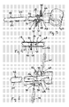
- Fig. 1 is a simplified side view of a grain header supported on a feeder on the front end of an agricultural combine, and showing in dotted lines a gathering auger on the header, including an array of auger fingers of the invention extending radially outwardly from a drum of the auger at angularly spaced locations therearound;
- Fig. 2 is a simplified schematic side view of the header and auger of Fig. 1, illustrating one of the auger fingers at several rotational positions of the drum of the auger;
- Fig. 3 is a perspective view of the auger finger of Fig. 2, shown mounted on a mounting sleeve mountable on an auger finger shaft of the drum;
- Fig. 4 is a fragmentary side view of the auger finger of Fig. 2;
- Fig. 5 is a perspective view of the auger finger, with tethers of the invention shown in exploded form, illustrating assembly thereof;
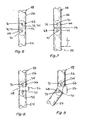
- Fig. 6 is another fragmentary side view of the auger finger;
- Fig. 7 is a fragmentary side view of the auger finger, showing breakage of a failure region thereof;
- Fig. 8 is another fragmentary side view of the auger finger, showing separation of free and mounting end portions of the finger and retention of the free end portion by the tethers of the invention;
- Fig. 9 is another fragmentary side view of the auger finger, illustrating relative pivotal movement of the mounting and free end portions thereof when the failure region is broken;
- Fig. 10 is a simplified schematic side view of the header of Fig. 1, illustrating rotation of the auger thereof with a finger of the auger in a first rotational position;
- Fig. 11 is another simplified schematic side view of the header, illustrating rotation of the auger such that the finger is brought into contact with a hard object on a pan of the header;
- Fig. 12 is another simplified schematic side view of the header, illustrating further rotation of the auger and breakage of a failure region of the finger as a result the contact with the hard object and subsequent retention of the broken free end portion of the finger;
- Fig. 13 is another simplified schematic side view of the header, showing still further rotation of the auger to cause partial retraction of the broken portion of the finger into a drum of the auger;
- Fig. 14 is another simplified schematic side view of the header, showing the broken finger portion fully retracted into the drum; and
- Fig. 15 is another simplified schematic side view of the header, showing a resting position of the broken finger portion within the drum.
- Referring now to the drawings, in Fig. 1, the front end of a conventional
agricultural combine 20 is shown, including afeeder 22 supporting agrain header 24 conventionally operable for cutting and gathering crops containing grain, such as wheat and other grasses, legumes such as soybeans, and the like, in the well known conventional manner.Header 24 has afront end 26 includingcutter apparatus 28 extending along the width thereof, configured and operable for severing crops (not shown) from the ground during movement of combine 20 in a forward direction, denoted by arrow F. -
Header 24 includes areel 30 disposed abovecutter apparatus 28 and rotatable for directing the cut crops rearwardly onto and along a generally flat, horizontal floor orpan 32 ofheader 24, into agathering auger 34 extending across the width of the header adjacent to the rear ofpan 32. Auger 34 includes a hollowcylindrical drum 36 having opposite right hand and left hand helical flights 38 and 40 extending around opposite end portions thereof, respectively. Auger 34 is rotatable about a rotational axis 42 (Fig. 2), and flights 38 and 40 are rotatable therewith for conveying crop material from opposite end regions of the header toward the center region thereof.Feeder 22 includes an inlet opening (not shown) just rearwardly of the center region ofheader 24, for receiving the augered crops, in the well known manner. - To facilitate flow and induction of the crops into the inlet of
feeder 22,drum 36 includes an array ofauger fingers 48 at longitudinally and angularly spaced locations therearound which rotate therewith and are configured to reciprocally move telescopically radially outwardly therefrom and radially inwardly therein during the rotation, for raking the crop material intofeeder 22, in the well known manner. - Referring also to Fig. 2,
auger 34 ofheader 24 is shown. The rotation ofauger 34 is denoted by arrow B, aboutaxis 42 throughdrum 36. As noted above,drum 36 is hollow, and it includes a longitudinally and angularly spaced array of holes through an outercylindrical surface 44 thereof, represented byhole 46. An auger finger constructed and operable according to the teachings of the invention, is positioned in and extends outwardly through each of the holes of the array, as illustrated byauger finger 48 inhole 46. As will be explained, each of the auger fingers, as represented byauger finger 48, telescopically extends outwardly through its hole, represented by ahole 46, by a different amount, depending on the rotational position ofdrum 36 aboutaxis 42. To illustrate,auger finger 48 is shown in a first rotational position telescopically extending in an upwardly and forwardly directed orientation fromdrum 36, in preparation for raking. - The auger finger is denoted by
number 48A at a second rotational position ofdrum 36, telescopically extending forwardly and downwardly in a raking position and orientation. The auger finger is denoted by number 48B at a third rotational position of the drum, extending rearwardly and downwardly and mostly telescopically retracted into the drum. And, the auger is denoted bynumber 48C in a rearward and upwardly directed orientation re-emerging from the drum. Thus, it should be evident that by rotation ofdrum 36 in the direction denoted by arrow B in Fig. 2, an auger finger will project telescopically a substantial distance fromdrum 36 in a gathering or raking mode through a portion of a revolution of the drum, as denoted bynumbers drum 36 through another portion of the revolution, as denoted bynumber 48B and 48C, once the crop has been raked rearwardly into the feeder. - Referring also to Figs. 2, 3, 4 and 5, each of the auger fingers of the invention, represented by
auger finger 48, includes an elongaterigid body 50 constructed of a suitable material such as, but not limited to, a metal such as steel or aluminium.Body 50 includes amounting end portion 52, afree end portion 54, and afailure region 56 at a predetermined location between mounting andfree end portions portions region 56 is preferably located in relation to mountingend portion 52, so as to be located at all times within aninternal cavity 58 ofdrum 36, whilefree end portion 54 extends radially outwardly fromdrum 36 through the range of rotational positions thereof, as best illustrated in Fig. 2. -
Mounting end portion 52 is adapted to be received and held in a hole through a side of a mounting flange or sleeve, illustrated by mounting sleeve 60 in Figs. 2 and 3, which in turn, is mounted for rotation about a sidewardly extendingauger finger shaft 62 located ininternal cavity 58 ofdrum 36.Auger finger shaft 62 is mounted at a fixed location withininternal cavity 58 in axially offset relation toaxis 42, such that the mounting sleeves, represented by sleeve 60, will be rotatable about an augerfinger shaft axis 64 extending longitudinally throughshaft 62.Mounting end portion 52 can be secured to sleeve 60 in any desired manner, such as by using one or more commercially available roll pins or fasteners, or by threaded engagement, or the like, in the well known manner, preferably so as to enable easy and quick removal and replacement. -
Failure region 56 can comprise any suitable construction which will result in breakage ofbody 50 at that location as a result of application of at least a predetermined threshold side loading condition, the magnitude of which can be determined as required or desired for a particular application, it being understood thatfailure region 56 is to be weaker than at least mountingend portion 52, such that in the event of application of a side load against the finger of at least the threshold value, the finger will break atfailure region 56 and not at mountingend portion 52 or another undesired location. To provide this capability,failure region 56 can comprise suitable structure, such as a circumferential groove aroundbody 50, a notch, or the like, to provide the desired weakening so as to be subject to breakage before other portions ofbody 50, particularly mountingend portion 52. - As noted above, in the event of breakage of a finger, such as
finger 48 atfailure region 56, it is desirable for the broken or detachedfree end portion 54 to be retained in connection withdrum 36, so as not to be subject to induction intofeeder 22 and subsequent conveyance or passage into other regions ofcombine 20 wherein consequential damage therefrom could result. It has likewise been found to be undesirable for the broken portion of a finger to flail about the exterior ofdrum 36 so as to cause noise and potentially damage nearby components ofheader 24. Thus, it has been found to be desirable to have the capability to retract a broken segment of a finger intointernal cavity 58 and to hold the broken portion therein in a position and orientation so as to cause no further damage. - This desirable capability is achieved according to the present invention by providing at least one
tether 66, and preferably twotethers 66, connected between mountingend portion 52 andfree end portion 54 of each auger finger, so as to spanfailure region 56 thereof and hold or retainfree end portion 54 in theevent failure region 56 is broken.Tether 66 additionally preferably allows relative pivotal movement of mountingend portion 52 andfree end portion 54, to allow passage offree end portion 54 over an object contact with which caused the breakage offailure region 56, and to allow and facilitate retraction offree end portion 54 throughhole 46 intointernal cavity 58 ofdrum 36, by continued rotation of the drum. - To provide this capability,
tether 66 preferably includes arigid link 68 which spansfailure region 56 and includes a pair ofholes 70 there through which align withholes 72 through mountingend portion 52 andfree end portion 54, so as to jointly receive suitable retaining elements there through. Here, thetethers 66 are shown on opposite sides offinger 48, respectively, held in position by a pair of retaining elements which are lockingsafety pins 74. This configuration is desirable and preferred, as it will allow relative pivotal movement between mountingend portion 52 andfree end portion 54 whenfailure region 56 is broken, only in a transverse direction generally perpendicular toholes 72 throughend portions locking safety pins 74, is that they can be easily and conveniently manually removed, to allow removal oftethers 66, and removal offree end portion 54 from mountingend 52 whenfailure region 56 is broken. - Referring also to Figs. 6, 7, 8 and 9, a sequence of steps failure or breakage of
failure region 56 and resultant relative pivotability ofend portions finger 48 as facilitated bytethers 66, is shown. Here, it should first be observed that so as to provide the capability of easy relative pivotal movement of mountingend portion 52 andfree end portion 54 in the event of breakage offailure region 56, tethers 66 are configured to allow a limited amount of relative longitudinal movement of mountingend portion 52 andfree end portion 54 upon breakage offailure region 56, to provide clearance for the edges of the broken region to pivot past one another. This capability is preferably provided by at least one, and more preferably both, ofholes 70 throughlink 68 of eachtether 66 being elongate longitudinally relative tofinger 48, or otherwise suitably enlarged. - Referring more particularly to Fig. 6,
failure region 56 is shown intact, andsafety pins 74 extend throughholes 70 inlink 68 oftether 66 and holes 72 inend portions failure region 56 is shown fractured or broken, as a result of application of a side load, denoted by arrow L, againstfree end portion 54, free end portion being retained onend portion 52 bytether 66. In Fig. 8,failure region 56 is shown broken apart, such thatfree end portion 54 is longitudinally spaced from mountingend portion 52 while still being retained bytether 66, pins 74 now being located at the opposite ends ofelongate holes 70 oflink 68. - Fig. 9 illustrates pivoting of
free end portion 54 relative to mountingend portion 52, as allowed by the now existent space therebetween resulting from fracture and breakage offailure region 56, and the elongation ofholes 70 oftether 66 which still retains the end portions together. This pivotability is useful and desirable, for instance, to allowfree end portion 54 offinger 48 to pass over an object contacted byfree end portion 54 which resulted in the application of load L thereagainst and the breakage offailure region 56, as will be illustrated. The pivotability also has utility for facilitating automatic retraction offree end portion 54 into the auger drum, as will be illustrated. - Figs 10, 11, 12, 13, 14 and 15 show a sequence of rotation of
auger 34 ofheader 24 resulting in breakage offailure region 56 ofauger finger 48 caused by contact with ahard object 76 conveyed ontopan 32 ofheader 24 and too large to pass betweenpan 32 and the bottom ofdrum 36 ofauger 34. This is intended to be illustrative of a wide variety of incidents that may result in breakage of a finger, such as, but not limited to, contact with a large stone or rock, a fence post, log or stump, an animal carcass or skeleton, or a part or parts of any of these. - More particularly, in Fig. 10,
auger 34 is shown rotating in direction B withfree end portion 54 offinger 48 extending radially outwardly throughhole 46 ofdrum 36, mountingend portion 52 andfailure region 56 being disposed ininternal cavity 58 ofdrum 36. In Fig. 11,hard object 76 is shown lodged betweenpan 32 and the bottom ofdrum 36, which has rotated to bringfree end portion 54 offinger 48 into contact withhard object 76. Mountingend portion 52 andfailure region 56 offinger 48 are located ininternal cavity 58 ofdrum 36. - Fig. 12 shows subsequent rotation of
auger 34 such that a side load L is applied byhard object 76 againstfree end portion 54 offinger 48, resulting in failure or breakage offailure region 56 offinger 48, retention offree end portion 54 on mountingend portion 52 bytethers 66, and pivotally movement offree end portion 54 relative to mountingend portion 52, as allowed and facilitated bytethers 66. With breakage offailure region 56,free end portion 54 offinger 48 is allowed to be longitudinally displaced from mountingend portion 52 as explained above, again as facilitated bytethers 66, to allow and facilitate the pivotally movement offree end portion 54 and also the continued rotation ofauger 34, without subjecting mountingend portion 52 as structure in support thereof to increased loads, which could be potentially damaging thereto or to related componentry. - In Fig. 13,
free end portion 54 offinger 48 is shown retracted almost fully throughhole 46 intointernal cavity 58 so as to facilitate passage over a hard object 76 (Figs. 10-12) and continued rotation ofauger 34, as facilitated bytethers 66. In Fig. 14,free end portion 54 offinger 48 is shown removed fromhole 46 bytethers 66, in cooperation with continued rotation ofauger 34, so as to be located completely withininternal cavity 58, mountingend portion 52 being freely rotatable with mounting sleeve 60 about auger finger shaft 62 (Fig. 2) to facilitate this. In Fig. 15, during continued rotation ofauger 34,broken finger 48 is shown in a rest position withfree end portion 54 resting against an internal surface ofdrum 36.Free end portion 54 will now be retained in this position bytether 66 throughout any subsequent rotation ofauger 34.
Claims (14)
- A finger (48) for an auger for an agricultural harvesting machine (20), comprising:- a mounting end portion (52);- an elongate free end portion (54) opposite the mounting end portion (52); and- a failure region (56) at a predetermined location connecting the mounting (52) and free end (54) portions, the failure region (56) being constructed to be weaker than at least the mounting end portion (52) so as to break and disconnect the mounting (52) and free end (54) portions when the finger (48) is subjected to a threshold load condition (L);characterised in that the finger (48) further comprises at least one tether (66) connected between the free (54) and mounting (52) end portions and spanning the failure region (56) for holding the free end portion (54) in connection with the mounting end portion (52) while allowing relative pivotal movement therebetween if the failure region (56) is broken.
- The auger finger (48) as claimed in claim 1, wherein the at least one tether (66) comprises a rigid link (68) configured to allow pivotal movement of the free end portion (54) relative to the mounting end portion (52) when the failure region (56) is broken.
- The auger finger (48) as claimed in claim 2, wherein the rigid link (68) has one end pivotally connected to the free end portion (54) and an opposite end pivotally connected to the mounting end portion (52), the rigid link (68) being configured to allow the free end portion (54) and the mounting end portion (52) to move a controlled distance apart when the failure region (56) is broken to facilitate the relative pivotal movement of the free (54) and mounting (52) end portions.
- The auger finger (48) as claimed in any of the preceding claims, wherein two tethers are connected on opposite sides of the failure region (56), respectively.
- The auger finger (48) as claimed in any of the preceding claims, wherein when the failure region (56) is broken, the at least one tether (66) will allow the relative pivotal movement of the mounting (52) and free (54) end portions only in a predetermined transverse direction.
- The auger finger (48) as claimed in claim 5, wherein the predetermined transverse direction is a direction of rotation (B) of an auger (34) on which the finger (48) is mounted.
- The auger finger (48) as claimed any of the preceding claims, wherein the failure region (56) comprises a groove in the finger (48).
- The auger finger (48) as claimed in any of the preceding claims, wherein the at least one tether (66) is connected to the mounting (52) and free (54) end portions by manually removable devices (74) to allow removal of the free end portion (54) from the mounting end portion (52) when the failure region (56) is broken.
- An auger (34) comprising a hollow drum (36) and at least one auger finger (48) as claimed in any of the preceding claims, wherein the mounting end (52) of the finger (48) is mounted in an internal cavity (58) of the hollow drum (36) of the auger (34), such that the failure region (56) is located within the cavity (58) and the free end portion (52) extends outwardly from a hole (46) in the drum (36).
- The auger (34) as claimed in claim 9, wherein the at least one tether (66) is configured such that if the failure region (56) breaks during rotation of the drum (36) the at least one tether (66) will retract the entire free end portion (54) through the hole (46) and into the cavity (58) within about one further revolution of the drum (36) and thereafter retain the free end portion (54) in the cavity (58).
- A method for securing a finger (48) for an auger (34) for an agricultural harvesting machine (20), the finger (48) having a mounting end portion (52), an elongate free end portion (52) and a failure region (56) between the mounting (52) and free (54) end portion of the finger (48), the free end portion (54) of the finger (48) extending radially outwardly through a hole (46) of a drum (36) of the auger (34) and the mounting end portion (52) and the failure region (56) being disposed in the internal cavity (58) of the drum (36), the method comprising the steps of:- rotating the finger (48) of the auger (34) in a direction (B);- contacting the finger (48) with a hard object (76) such that a side load (L) is applied by the hard object (76) against the free end portion (54) of the finger (48); and- breaking of the failure region (56),characterized in that the method comprises the further step of retaining, during subsequent rotation of the drum (36), the free end portion (54) on the mounting end portion (52) by at least one tether (66) thereby preventing undesirable movement of the broken end (54).
- A method as claimed in claim 11, wherein the retaining step further allows pivotal movement of the free end portion (54) only in a direction of rotation of the drum.
- A method as claimed in claim 11 or 12, wherein the retaining step further allows a longitudinal displacement of the free end portion (54) from the mounting end portion (52).
- A method as claimed in any of the claims 11 to 13, the method further comprises the steps of- automatically retracting the free end portion (54) into the cavity (58) of the drum (36) and- retaining the free end portion (54) in the cavity (58).
Applications Claiming Priority (1)
| Application Number | Priority Date | Filing Date | Title |
|---|---|---|---|
| US11/194,226 US7401457B2 (en) | 2005-08-01 | 2005-08-01 | Auger finger with tether for retaining and retracting the finger when broken |
Publications (2)
| Publication Number | Publication Date |
|---|---|
| EP1749436A1 true EP1749436A1 (en) | 2007-02-07 |
| EP1749436B1 EP1749436B1 (en) | 2010-03-03 |
Family
ID=37395754
Family Applications (1)
| Application Number | Title | Priority Date | Filing Date |
|---|---|---|---|
| EP06117879A Expired - Lifetime EP1749436B1 (en) | 2005-08-01 | 2006-07-26 | Auger finger with tether for retaining and retracting the finger when broken |
Country Status (5)
| Country | Link |
|---|---|
| US (1) | US7401457B2 (en) |
| EP (1) | EP1749436B1 (en) |
| AT (1) | ATE459240T1 (en) |
| BR (1) | BRPI0601545B1 (en) |
| DE (1) | DE602006012589D1 (en) |
Cited By (3)
| Publication number | Priority date | Publication date | Assignee | Title |
|---|---|---|---|---|
| EP1908341A1 (en) * | 2006-10-06 | 2008-04-09 | CNH Belgium N.V. | Auger finger with resilient elastomeric retainer retractor |
| WO2008151210A1 (en) * | 2007-06-04 | 2008-12-11 | Lord Corporation | Retention device for separating combine auger finger materials and agricultural material engagement method |
| EP3072381A1 (en) | 2015-03-24 | 2016-09-28 | CNH Industrial Belgium nv | An auger finger assembly for a harvesting machine |
Families Citing this family (7)
| Publication number | Priority date | Publication date | Assignee | Title |
|---|---|---|---|---|
| DE102005016976A1 (en) * | 2005-04-13 | 2006-11-02 | Deere & Company, Moline | Carrier unit of a rotary conveyor |
| US7669396B2 (en) * | 2007-08-23 | 2010-03-02 | Deere & Company | Timing crank and cylindrical conveyor for an agricultural harvester |
| US7937921B2 (en) | 2008-03-03 | 2011-05-10 | Agco Corporation | Break-away finger for retracting finger auger |
| BRPI0903650B1 (en) * | 2009-09-17 | 2018-02-06 | Agco Do Brasil Máquinas E Equipamentos Agrícolas Ltda. | RETRACTABLE FINGER FOR ASSEMBLY ON A MAIN GRAIN HARVEST SNAIL |
| DE102012109269A1 (en) * | 2012-09-28 | 2014-05-15 | Claas Hungaria Kft. | Carrier device of a conveyor |
| BR102019007286A2 (en) | 2018-04-11 | 2019-10-29 | Cnh Ind America Llc | toothed tube for screw conveyor thread |
| CN110810020B (en) * | 2019-12-12 | 2024-11-22 | 日照市勇杰农业装备有限公司 | Self-propelled peanut harvester |
Citations (3)
| Publication number | Priority date | Publication date | Assignee | Title |
|---|---|---|---|---|
| EP0371372A1 (en) | 1988-11-29 | 1990-06-06 | Deere & Company | Pick-up device for a rotating conveyor |
| EP0933017A1 (en) * | 1998-01-29 | 1999-08-04 | Deere & Company | Transporting device with rotating and at least driving element and harvester with such a transporting device |
| EP1712121A1 (en) * | 2005-04-13 | 2006-10-18 | Deere & Company | Pick-up device for a rotating conveyor |
Family Cites Families (18)
| Publication number | Priority date | Publication date | Assignee | Title |
|---|---|---|---|---|
| US3126693A (en) | 1964-03-31 | Flexible grain pickup elements and mounting | ||
| US2701634A (en) | 1950-04-22 | 1955-02-08 | Massey Harris Co Ltd | Rotatable crop feeder with bearings for retracting fingers |
| US3175347A (en) * | 1963-05-09 | 1965-03-30 | Hart Carter Co | Tine mounting |
| US3912404A (en) | 1975-01-02 | 1975-10-14 | Herbert L Katt | Highway post construction |
| DE2645174C2 (en) | 1976-10-07 | 1982-08-12 | Messerschmitt-Bölkow-Blohm GmbH, 8000 München | Rotor head for a non-flapping and swivel-jointless rotor |
| US4214511A (en) | 1979-06-04 | 1980-07-29 | Mueller Gary E | Break-away vent for grain storage bins |
| US4271956A (en) | 1979-12-17 | 1981-06-09 | Deere & Company | Finger construction for a combine platform auger |
| US4882899A (en) * | 1988-06-15 | 1989-11-28 | Hcc, Inc. | Harvester reel tine and bat assembly |
| WO1992003037A1 (en) * | 1990-08-14 | 1992-03-05 | Klinner Wilfred E | Means and method of securing and protecting crop engaging elements |
| US5484217A (en) | 1994-07-15 | 1996-01-16 | Decks, Inc. | Restorable breakaway post |
| US5511272A (en) | 1994-12-09 | 1996-04-30 | Belanger, Inc. | Pre-engineered failure link for brush shaft |
| US5595052A (en) | 1995-08-04 | 1997-01-21 | Deere & Company | Bat for a reel having an anti-wrap extension |
| US5884432A (en) | 1997-10-17 | 1999-03-23 | Delillo; Michael J. | Breakaway assembly for vehicle barrier device |
| US6199357B1 (en) * | 1998-11-13 | 2001-03-13 | Alamo Group Inc. | Reel pickup tine |
| US6467246B1 (en) * | 1999-03-24 | 2002-10-22 | Deere & Company | Knife section having breakage holes |
| US6158571A (en) | 1999-04-01 | 2000-12-12 | Deere & Company | Finger bearing assembly for a combine platform auger |
| US6668534B2 (en) | 2001-08-31 | 2003-12-30 | Deere & Company | Auger fingers for harvesting assemblies, and combines |
| US6640527B2 (en) | 2001-12-18 | 2003-11-04 | New Holland North America, Inc. | Center feed finger adjustment mechanism for header |
-
2005
- 2005-08-01 US US11/194,226 patent/US7401457B2/en not_active Expired - Fee Related
-
2006
- 2006-04-12 BR BRPI0601545-0A patent/BRPI0601545B1/en not_active IP Right Cessation
- 2006-07-26 AT AT06117879T patent/ATE459240T1/en not_active IP Right Cessation
- 2006-07-26 DE DE602006012589T patent/DE602006012589D1/en not_active Expired - Lifetime
- 2006-07-26 EP EP06117879A patent/EP1749436B1/en not_active Expired - Lifetime
Patent Citations (3)
| Publication number | Priority date | Publication date | Assignee | Title |
|---|---|---|---|---|
| EP0371372A1 (en) | 1988-11-29 | 1990-06-06 | Deere & Company | Pick-up device for a rotating conveyor |
| EP0933017A1 (en) * | 1998-01-29 | 1999-08-04 | Deere & Company | Transporting device with rotating and at least driving element and harvester with such a transporting device |
| EP1712121A1 (en) * | 2005-04-13 | 2006-10-18 | Deere & Company | Pick-up device for a rotating conveyor |
Cited By (3)
| Publication number | Priority date | Publication date | Assignee | Title |
|---|---|---|---|---|
| EP1908341A1 (en) * | 2006-10-06 | 2008-04-09 | CNH Belgium N.V. | Auger finger with resilient elastomeric retainer retractor |
| WO2008151210A1 (en) * | 2007-06-04 | 2008-12-11 | Lord Corporation | Retention device for separating combine auger finger materials and agricultural material engagement method |
| EP3072381A1 (en) | 2015-03-24 | 2016-09-28 | CNH Industrial Belgium nv | An auger finger assembly for a harvesting machine |
Also Published As
| Publication number | Publication date |
|---|---|
| BRPI0601545A (en) | 2007-03-13 |
| EP1749436B1 (en) | 2010-03-03 |
| DE602006012589D1 (en) | 2010-04-15 |
| US7401457B2 (en) | 2008-07-22 |
| BRPI0601545B1 (en) | 2014-12-09 |
| ATE459240T1 (en) | 2010-03-15 |
| US20070022727A1 (en) | 2007-02-01 |
Similar Documents
| Publication | Publication Date | Title |
|---|---|---|
| EP1908341B1 (en) | Auger finger with resilient elastomeric retainer retractor | |
| EP1749436B1 (en) | Auger finger with tether for retaining and retracting the finger when broken | |
| US5569080A (en) | Crop straw flow disruption device for use on crop harvesting machine separation grate | |
| US7059961B2 (en) | Apparatus and method for effecting movement and clearance spacing of a concave | |
| EP2854503B1 (en) | Folding auger assembly coupler | |
| US6158571A (en) | Finger bearing assembly for a combine platform auger | |
| DE60107171T2 (en) | Support structure for divider of a corn crop header | |
| US9924637B1 (en) | Helical auger flight assemblies and thresher formed therewith | |
| US7669396B2 (en) | Timing crank and cylindrical conveyor for an agricultural harvester | |
| US20100251683A1 (en) | Auger finger with resilient elastomeric retainer retractor | |
| EP4009769B1 (en) | Tool-less folding divider for combine head | |
| EP1500323B1 (en) | Crop processing element for a rotor of a crop treatment device of a combine harvester | |
| EP1712121B1 (en) | Pick-up device for a rotating conveyor | |
| US20060277889A1 (en) | Wind screen hold down attachment | |
| EP1514467B1 (en) | Mechanism for fixing a grid to a crop processing unit | |
| US4290259A (en) | Knife assembly for stripping auger drum of combine header | |
| EP1604561B1 (en) | Reel for a harvesting machine | |
| US20250151660A1 (en) | Sieve assembly for separating grains from plant residual material | |
| JP5021388B2 (en) | Combine weed divider structure | |
| AU2014202792A1 (en) | Harvesting cam reel with convertible transport mode | |
| AU8730301A (en) | Bearing assembly for a retractable auger finger | |
| JPH01211424A (en) | Device for mounting raking in tine of grain culm raking in reel | |
| JPH0795895B2 (en) | Combine threshing equipment |
Legal Events
| Date | Code | Title | Description |
|---|---|---|---|
| PUAI | Public reference made under article 153(3) epc to a published international application that has entered the european phase |
Free format text: ORIGINAL CODE: 0009012 |
|
| AK | Designated contracting states |
Kind code of ref document: A1 Designated state(s): AT BE BG CH CY CZ DE DK EE ES FI FR GB GR HU IE IS IT LI LT LU LV MC NL PL PT RO SE SI SK TR |
|
| AX | Request for extension of the european patent |
Extension state: AL BA HR MK YU |
|
| 17P | Request for examination filed |
Effective date: 20070807 |
|
| AKX | Designation fees paid |
Designated state(s): AT BE BG CH CY CZ DE DK EE ES FI FR GB GR HU IE IS IT LI LT LU LV MC NL PL PT RO SE SI SK TR |
|
| 17Q | First examination report despatched |
Effective date: 20070925 |
|
| GRAP | Despatch of communication of intention to grant a patent |
Free format text: ORIGINAL CODE: EPIDOSNIGR1 |
|
| GRAS | Grant fee paid |
Free format text: ORIGINAL CODE: EPIDOSNIGR3 |
|
| GRAA | (expected) grant |
Free format text: ORIGINAL CODE: 0009210 |
|
| AK | Designated contracting states |
Kind code of ref document: B1 Designated state(s): AT BE BG CH CY CZ DE DK EE ES FI FR GB GR HU IE IS IT LI LT LU LV MC NL PL PT RO SE SI SK TR |
|
| REG | Reference to a national code |
Ref country code: GB Ref legal event code: FG4D |
|
| REG | Reference to a national code |
Ref country code: CH Ref legal event code: EP |
|
| REG | Reference to a national code |
Ref country code: IE Ref legal event code: FG4D |
|
| REF | Corresponds to: |
Ref document number: 602006012589 Country of ref document: DE Date of ref document: 20100415 Kind code of ref document: P |
|
| REG | Reference to a national code |
Ref country code: NL Ref legal event code: VDEP Effective date: 20100303 |
|
| PG25 | Lapsed in a contracting state [announced via postgrant information from national office to epo] |
Ref country code: LT Free format text: LAPSE BECAUSE OF FAILURE TO SUBMIT A TRANSLATION OF THE DESCRIPTION OR TO PAY THE FEE WITHIN THE PRESCRIBED TIME-LIMIT Effective date: 20100303 |
|
| LTIE | Lt: invalidation of european patent or patent extension |
Effective date: 20100303 |
|
| PG25 | Lapsed in a contracting state [announced via postgrant information from national office to epo] |
Ref country code: FI Free format text: LAPSE BECAUSE OF FAILURE TO SUBMIT A TRANSLATION OF THE DESCRIPTION OR TO PAY THE FEE WITHIN THE PRESCRIBED TIME-LIMIT Effective date: 20100303 Ref country code: AT Free format text: LAPSE BECAUSE OF FAILURE TO SUBMIT A TRANSLATION OF THE DESCRIPTION OR TO PAY THE FEE WITHIN THE PRESCRIBED TIME-LIMIT Effective date: 20100303 Ref country code: PL Free format text: LAPSE BECAUSE OF FAILURE TO SUBMIT A TRANSLATION OF THE DESCRIPTION OR TO PAY THE FEE WITHIN THE PRESCRIBED TIME-LIMIT Effective date: 20100303 Ref country code: LV Free format text: LAPSE BECAUSE OF FAILURE TO SUBMIT A TRANSLATION OF THE DESCRIPTION OR TO PAY THE FEE WITHIN THE PRESCRIBED TIME-LIMIT Effective date: 20100303 Ref country code: SI Free format text: LAPSE BECAUSE OF FAILURE TO SUBMIT A TRANSLATION OF THE DESCRIPTION OR TO PAY THE FEE WITHIN THE PRESCRIBED TIME-LIMIT Effective date: 20100303 |
|
| PG25 | Lapsed in a contracting state [announced via postgrant information from national office to epo] |
Ref country code: ES Free format text: LAPSE BECAUSE OF FAILURE TO SUBMIT A TRANSLATION OF THE DESCRIPTION OR TO PAY THE FEE WITHIN THE PRESCRIBED TIME-LIMIT Effective date: 20100614 Ref country code: CY Free format text: LAPSE BECAUSE OF FAILURE TO SUBMIT A TRANSLATION OF THE DESCRIPTION OR TO PAY THE FEE WITHIN THE PRESCRIBED TIME-LIMIT Effective date: 20100303 Ref country code: SE Free format text: LAPSE BECAUSE OF FAILURE TO SUBMIT A TRANSLATION OF THE DESCRIPTION OR TO PAY THE FEE WITHIN THE PRESCRIBED TIME-LIMIT Effective date: 20100303 Ref country code: NL Free format text: LAPSE BECAUSE OF FAILURE TO SUBMIT A TRANSLATION OF THE DESCRIPTION OR TO PAY THE FEE WITHIN THE PRESCRIBED TIME-LIMIT Effective date: 20100303 Ref country code: RO Free format text: LAPSE BECAUSE OF FAILURE TO SUBMIT A TRANSLATION OF THE DESCRIPTION OR TO PAY THE FEE WITHIN THE PRESCRIBED TIME-LIMIT Effective date: 20100303 Ref country code: BE Free format text: LAPSE BECAUSE OF FAILURE TO SUBMIT A TRANSLATION OF THE DESCRIPTION OR TO PAY THE FEE WITHIN THE PRESCRIBED TIME-LIMIT Effective date: 20100303 Ref country code: EE Free format text: LAPSE BECAUSE OF FAILURE TO SUBMIT A TRANSLATION OF THE DESCRIPTION OR TO PAY THE FEE WITHIN THE PRESCRIBED TIME-LIMIT Effective date: 20100303 |
|
| PG25 | Lapsed in a contracting state [announced via postgrant information from national office to epo] |
Ref country code: BG Free format text: LAPSE BECAUSE OF FAILURE TO SUBMIT A TRANSLATION OF THE DESCRIPTION OR TO PAY THE FEE WITHIN THE PRESCRIBED TIME-LIMIT Effective date: 20100603 Ref country code: CZ Free format text: LAPSE BECAUSE OF FAILURE TO SUBMIT A TRANSLATION OF THE DESCRIPTION OR TO PAY THE FEE WITHIN THE PRESCRIBED TIME-LIMIT Effective date: 20100303 Ref country code: IS Free format text: LAPSE BECAUSE OF FAILURE TO SUBMIT A TRANSLATION OF THE DESCRIPTION OR TO PAY THE FEE WITHIN THE PRESCRIBED TIME-LIMIT Effective date: 20100703 Ref country code: SK Free format text: LAPSE BECAUSE OF FAILURE TO SUBMIT A TRANSLATION OF THE DESCRIPTION OR TO PAY THE FEE WITHIN THE PRESCRIBED TIME-LIMIT Effective date: 20100303 |
|
| PLBE | No opposition filed within time limit |
Free format text: ORIGINAL CODE: 0009261 |
|
| STAA | Information on the status of an ep patent application or granted ep patent |
Free format text: STATUS: NO OPPOSITION FILED WITHIN TIME LIMIT |
|
| PG25 | Lapsed in a contracting state [announced via postgrant information from national office to epo] |
Ref country code: DK Free format text: LAPSE BECAUSE OF FAILURE TO SUBMIT A TRANSLATION OF THE DESCRIPTION OR TO PAY THE FEE WITHIN THE PRESCRIBED TIME-LIMIT Effective date: 20100303 Ref country code: PT Free format text: LAPSE BECAUSE OF FAILURE TO SUBMIT A TRANSLATION OF THE DESCRIPTION OR TO PAY THE FEE WITHIN THE PRESCRIBED TIME-LIMIT Effective date: 20100705 |
|
| 26N | No opposition filed |
Effective date: 20101206 |
|
| PG25 | Lapsed in a contracting state [announced via postgrant information from national office to epo] |
Ref country code: MC Free format text: LAPSE BECAUSE OF NON-PAYMENT OF DUE FEES Effective date: 20100731 |
|
| REG | Reference to a national code |
Ref country code: CH Ref legal event code: PL |
|
| PG25 | Lapsed in a contracting state [announced via postgrant information from national office to epo] |
Ref country code: LI Free format text: LAPSE BECAUSE OF NON-PAYMENT OF DUE FEES Effective date: 20100731 Ref country code: CH Free format text: LAPSE BECAUSE OF NON-PAYMENT OF DUE FEES Effective date: 20100731 |
|
| PG25 | Lapsed in a contracting state [announced via postgrant information from national office to epo] |
Ref country code: IE Free format text: LAPSE BECAUSE OF NON-PAYMENT OF DUE FEES Effective date: 20100726 |
|
| PG25 | Lapsed in a contracting state [announced via postgrant information from national office to epo] |
Ref country code: HU Free format text: LAPSE BECAUSE OF FAILURE TO SUBMIT A TRANSLATION OF THE DESCRIPTION OR TO PAY THE FEE WITHIN THE PRESCRIBED TIME-LIMIT Effective date: 20100904 Ref country code: LU Free format text: LAPSE BECAUSE OF NON-PAYMENT OF DUE FEES Effective date: 20100726 |
|
| PG25 | Lapsed in a contracting state [announced via postgrant information from national office to epo] |
Ref country code: TR Free format text: LAPSE BECAUSE OF FAILURE TO SUBMIT A TRANSLATION OF THE DESCRIPTION OR TO PAY THE FEE WITHIN THE PRESCRIBED TIME-LIMIT Effective date: 20100303 |
|
| REG | Reference to a national code |
Ref country code: DE Ref legal event code: R082 Ref document number: 602006012589 Country of ref document: DE Representative=s name: PATENTANWAELTE WALLACH, KOCH & PARTNER, DE |
|
| REG | Reference to a national code |
Ref country code: DE Ref legal event code: R081 Ref document number: 602006012589 Country of ref document: DE Owner name: CNH INDUSTRIAL BELGIUM NV, BE Free format text: FORMER OWNER: CNH BELGIUM NV, ZEDELGEM, BE Effective date: 20140428 Ref country code: DE Ref legal event code: R082 Ref document number: 602006012589 Country of ref document: DE Representative=s name: PATENTANWAELTE WALLACH, KOCH & PARTNER, DE Effective date: 20140428 Ref country code: DE Ref legal event code: R082 Ref document number: 602006012589 Country of ref document: DE Representative=s name: PATENTANWAELTE WALLACH, KOCH, DR. HAIBACH, FEL, DE Effective date: 20140428 |
|
| PG25 | Lapsed in a contracting state [announced via postgrant information from national office to epo] |
Ref country code: GR Free format text: LAPSE BECAUSE OF FAILURE TO SUBMIT A TRANSLATION OF THE DESCRIPTION OR TO PAY THE FEE WITHIN THE PRESCRIBED TIME-LIMIT Effective date: 20100303 |
|
| REG | Reference to a national code |
Ref country code: FR Ref legal event code: CD Owner name: CNH INDUSTRIAL BELGIUM NV Effective date: 20140725 |
|
| REG | Reference to a national code |
Ref country code: FR Ref legal event code: PLFP Year of fee payment: 11 |
|
| REG | Reference to a national code |
Ref country code: FR Ref legal event code: PLFP Year of fee payment: 12 |
|
| REG | Reference to a national code |
Ref country code: FR Ref legal event code: PLFP Year of fee payment: 13 |
|
| PGFP | Annual fee paid to national office [announced via postgrant information from national office to epo] |
Ref country code: IT Payment date: 20190711 Year of fee payment: 14 |
|
| PGFP | Annual fee paid to national office [announced via postgrant information from national office to epo] |
Ref country code: GB Payment date: 20190724 Year of fee payment: 14 |
|
| REG | Reference to a national code |
Ref country code: DE Ref legal event code: R084 Ref document number: 602006012589 Country of ref document: DE |
|
| REG | Reference to a national code |
Ref country code: DE Ref legal event code: R082 Ref document number: 602006012589 Country of ref document: DE Representative=s name: MEISSNER BOLTE PATENTANWAELTE RECHTSANWAELTE P, DE |
|
| GBPC | Gb: european patent ceased through non-payment of renewal fee |
Effective date: 20200726 |
|
| PG25 | Lapsed in a contracting state [announced via postgrant information from national office to epo] |
Ref country code: GB Free format text: LAPSE BECAUSE OF NON-PAYMENT OF DUE FEES Effective date: 20200726 |
|
| PG25 | Lapsed in a contracting state [announced via postgrant information from national office to epo] |
Ref country code: IT Free format text: LAPSE BECAUSE OF NON-PAYMENT OF DUE FEES Effective date: 20200726 |
|
| PGFP | Annual fee paid to national office [announced via postgrant information from national office to epo] |
Ref country code: FR Payment date: 20230721 Year of fee payment: 18 |
|
| PG25 | Lapsed in a contracting state [announced via postgrant information from national office to epo] |
Ref country code: FR Free format text: LAPSE BECAUSE OF NON-PAYMENT OF DUE FEES Effective date: 20240731 |
|
| PGFP | Annual fee paid to national office [announced via postgrant information from national office to epo] |
Ref country code: DE Payment date: 20250728 Year of fee payment: 20 |
|
| REG | Reference to a national code |
Ref country code: DE Ref legal event code: R071 Ref document number: 602006012589 Country of ref document: DE |