EP1500323B1 - Crop processing element for a rotor of a crop treatment device of a combine harvester - Google Patents
Crop processing element for a rotor of a crop treatment device of a combine harvester Download PDFInfo
- Publication number
- EP1500323B1 EP1500323B1 EP04103388A EP04103388A EP1500323B1 EP 1500323 B1 EP1500323 B1 EP 1500323B1 EP 04103388 A EP04103388 A EP 04103388A EP 04103388 A EP04103388 A EP 04103388A EP 1500323 B1 EP1500323 B1 EP 1500323B1
- Authority
- EP
- European Patent Office
- Prior art keywords
- crop
- rotor
- crop processing
- processing element
- drum
- Prior art date
- Legal status (The legal status is an assumption and is not a legal conclusion. Google has not performed a legal analysis and makes no representation as to the accuracy of the status listed.)
- Active
Links
- 238000010408 sweeping Methods 0.000 claims 1
- 239000002131 composite material Substances 0.000 description 4
- 239000000463 material Substances 0.000 description 4
- 238000004140 cleaning Methods 0.000 description 2
- 238000003306 harvesting Methods 0.000 description 2
- 239000010902 straw Substances 0.000 description 2
- 230000007704 transition Effects 0.000 description 2
- 241001124569 Lycaenidae Species 0.000 description 1
- 230000000712 assembly Effects 0.000 description 1
- 238000000429 assembly Methods 0.000 description 1
- 238000000926 separation method Methods 0.000 description 1
Images


Classifications
-
- A—HUMAN NECESSITIES
- A01—AGRICULTURE; FORESTRY; ANIMAL HUSBANDRY; HUNTING; TRAPPING; FISHING
- A01F—PROCESSING OF HARVESTED PRODUCE; HAY OR STRAW PRESSES; DEVICES FOR STORING AGRICULTURAL OR HORTICULTURAL PRODUCE
- A01F7/00—Threshing apparatus
- A01F7/02—Threshing apparatus with rotating tools
- A01F7/06—Threshing apparatus with rotating tools with axles in line with the feeding direction ; Axial threshing machines
-
- A—HUMAN NECESSITIES
- A01—AGRICULTURE; FORESTRY; ANIMAL HUSBANDRY; HUNTING; TRAPPING; FISHING
- A01F—PROCESSING OF HARVESTED PRODUCE; HAY OR STRAW PRESSES; DEVICES FOR STORING AGRICULTURAL OR HORTICULTURAL PRODUCE
- A01F12/00—Parts or details of threshing apparatus
- A01F12/18—Threshing devices
- A01F12/181—Adjustable threshing mechanisms
Definitions
- the invention relates to a crop processing element for a rotor of a crop processing device of a combine harvester.
- Combine harvesters are large machines that harvest, thresh, separate and clean agricultural crops.
- the resulting clean grain is stored in a grain tank arranged on the combine harvester. It can be unloaded from the grain tank to a truck, trailer or other container by a discharge auger.
- Rotary combine harvester has one or two large rotors for threshing and separating the crop.
- the rotor or rotors are aligned along the longitudinal axis of the combine. These rotors are provided with a feed section for accepting the harvested material, a threshing section for threshing the material from the feed section, and a separating section for releasing grains contained in the crop entering from the threshing section.
- Combine rotors have been provided in a variety of configurations to optimize harvest efficiency in a wide variety of crop types and conditions. For example, changes have been made to cylindrical and frusto-conical drum shapes as described in US Pat US 4 139 013 A . US 4 266 560 A and US 4,274,426 A were revealed.
- the object underlying the invention is seen to provide an improved rotor for a combine harvester.
- the present invention relates to a composite Erntegutbearbeitungselement for the rotor of a combine harvester, in particular a threshing element. It is placed on the drum of the rotor and comprises a hollow support structure having a plurality of outwardly extending Goodingriffsabêten which are offset in the axial and circumferential direction of the rotor against each other. Due to the one-piece stability of the Erntegutbearbeitungselements is improved, also it is more stable and inexpensive to produce.
- the Erntegutbearbeitungselement is alternatively or additionally equipped on its front with a Beschickungselementbefestrs adopted to which a rear portion of a preferably helical feed element is attached.
- the crop processing element may alternatively or additionally be configured to fit on a frusto-conical portion of the rotor, with its outer surface describing a cylindrical shell upon rotation of the rotor.
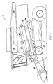
- FIG. 1 shows a combine harvester 10 having a supporting structure 12 with wheels 14 in engagement with the ground.
- the operation of the combine 10 is of a Operator's cab 15 off.
- a header 16 in the form of a header is used to pick up crop material and feed it to a feeder 18.
- the harvested material is fed from the feederhouse 18 a guide drum 20.
- the guide drum 20 leads the goods up through an inlet transition section 22 to a rotatable crop processing device 24.
- the rotatable crop processing device 24 threshes and separates the crop. Grain and chaff fall through grates at the bottom of the cropper 24 into a cleaning system 40.
- the cleaning system 40 removes the chaff and delivers the clean grain to a clean grain elevator (not shown).
- the clean grain elevator deposits the clean grain in a grain tank 28.
- the clean grain in the grain tank 28 may be unloaded by a discharge auger on a grain cart, trailer or truck.
- Threshed straw leaving the separation section is ejected from the crop processing unit 24 through an outlet 32 and fed to a conveyor drum 34.
- the conveyor drum 34 in turn ejects the straw at the back of the combine harvester 10.
- the axial crop processing device 24 comprises a rotor housing 36 and a rotor 37 arranged therein.
- the front part of the rotor 37 and the rotor housing 36 define the feed section 38 of the crop processing device 24.
- the threshing section 39 and the separating section 40 are the rotor 37 includes a drum 100 to which good processing elements for the loading section 38, the threshing section 39 and the separating section 40 are attached.
- the drum 100 includes a rearward cylindrical portion 102 and a forwardly extending frusto-conical portion 104.
- the surface of the frusto-conical portion 104 is divided into a rearward portion 106 proximate the rearward cylindrical portion 102 and a forward portion 108.
- the rotor 37 is provided in the feed section 38 with helical feed elements 42, which in the front region 108 of the frusto-conical portion 102 of the drum 100 are arranged.
- the helical feed elements 42 engage in the crop, which enters from the guide drum 20 and the inlet transition section 22.
- the feed elements 42 are composed of a front section 54 and a rear section 58.
- the front portion 54 of each loader 42 is bolted to the drum 100 by mounting assemblies 52.
- the rear portion 58 of each loader 42 is bolted to a loader fastener 128 which extends from an adjacent threshing member 120.
- the threshing section 39 of the crop processing device 24 Immediately downstream of the feed section 38 is the threshing section 39 of the crop processing device 24.
- the rotor 37 is equipped with a number of threshing elements 120 and 122 in order to thresh the crop fed by the loading section 38.
- the threshing members 122 are attached to the rear portion 106 of the frusto-conical portion 104, while the threshing members 120 are mounted to the rear cylindrical portion 102 of the drum 100.
- the threshing elements 120 on the cylindrical portion 102 of the drum 100 each include a hollow support structure having a good engagement portion 121.
- the thrusting elements 122 disposed at the rear portion 106 of the frusto-conical portion 104 of the drum 100 are composite threshing elements having a hollow support structure 124 with two outwardly extending engaging portions 126 which sweep a cylindrical path upon rotation of the rotor 100. Their outer surfaces are thus oriented parallel to the axis of the rotor 37. Extending from the threshing member 122 is the above-mentioned feed member mounting means 128 to which the rear portion 58 of the adjacent loader 42 is attached. The base of the threshing element 122 is provided with mounting flanges 130 through which fastening screws 57 extend to secure the threshing element 122 to the drum 100.
- the threshing elements 122 are shown in the illustrated embodiment with two engagement portions 126 mounted in a staggered arrangement, but could be provided with one or more good-fit portions in a variety of possible arrangements.
- the Gutingriffsabête 126 are also equipped with friction bars, but could also be provided with other surface profiles, as for example in the US 6 036 598 A are disclosed.
- the outwardly extending engaging portions 126 in the illustrated embodiment sweep a cylindrical path having a diameter that matches the diameter of the path swept by the engaging portion 121 of the threshing members 120 on the rear cylindrical portion 102 of the drum 100 of the rotor 37.
- the good engagement portions 126 of the composite threshing elements 122 could also be adapted to sweep cylindrical paths whose diameters differ from those of the good engagement portions 121 of the threshing elements 120 or adjacent good engagement portions 126 of the same threshing element 122.
Description
Die Erfindung betrifft ein Erntegutbearbeitungselement für einen Rotor einer Gutbearbeitungseinrichtung eines Mähdreschers.The invention relates to a crop processing element for a rotor of a crop processing device of a combine harvester.
Mähdrescher sind große Maschinen, die landwirtschaftlich angebautes Erntegut ernten, dreschen, trennen und reinigen. Das erhaltene saubere Korn wird in einem am Mähdrescher angeordneten Korntank gelagert. Es kann durch einen Entladeschneckenförderer aus dem Korntank auf einen Lastwagen, Anhänger oder in ein anderes Behältnis entladen werden.Combine harvesters are large machines that harvest, thresh, separate and clean agricultural crops. The resulting clean grain is stored in a grain tank arranged on the combine harvester. It can be unloaded from the grain tank to a truck, trailer or other container by a discharge auger.
Rotormähdrescher weisen einen oder zwei große Rotoren zum Dreschen und Trennen des Ernteguts auf. Bei den meisten Rotormähdreschern ist der Rotor oder sind die Rotoren entlang der Längsachse des Mähdreschers ausgerichtet. Diese Rotoren sind mit einem Beschickungsabschnitt zur Annahme des geernteten Materials, einem Dreschabschnitt zum Dreschen des Materials aus dem Beschickungsabschnitt und einem Trennabschnitt ausgestattet, um im vom Dreschabschnitt einlaufenden Erntegut enthaltene Körner freizusetzen.Rotary combine harvester has one or two large rotors for threshing and separating the crop. For most rotor combines, the rotor or rotors are aligned along the longitudinal axis of the combine. These rotors are provided with a feed section for accepting the harvested material, a threshing section for threshing the material from the feed section, and a separating section for releasing grains contained in the crop entering from the threshing section.
Rotoren für Mähdrescher wurden in einer Vielzahl von Konfigurationen bereitgestellt, um die Effizienz bei der Ernte bei einer großen Vielzahl an Erntegutarten und -bedingungen zu optimieren. Es wurden beispielweise Änderungen an zylindrischen und kegelstumpfförmigen Trommelformen durchgeführt, wie sie in der
Die der Erfindung zu Grunde liegende Aufgabe wird darin gesehen, einen verbesserten Rotor für einen Mähdrescher bereitzustellen.The object underlying the invention is seen to provide an improved rotor for a combine harvester.
Diese Aufgabe wird erfindungsgemäß durch die Lehre der Patentansprüche 1 und 5 gelöst, wobei in den weiteren Patentansprüchen Merkmale aufgeführt sind, die die Lösung in vorteilhafter Weise weiterentwickeln.This object is achieved by the teaching of claims 1 and 5, which are listed in the other claims features that further develop the solution in an advantageous manner.
Die vorliegende Erfindung bezieht sich auf ein zusammengesetztes Erntegutbearbeitungselement für den Rotor eines Mähdreschers, insbesondere ein Dreschelement. Es ist auf die Trommel des Rotors aufsetzbar und umfasst eine hohle Trägerstruktur mit mehreren sich nach außen erstreckenden Guteingriffsabschnitten, die in axialer und Umfangsrichtung des Rotors gegeneinander versetzt sind. Durch die Einteiligkeit wird die Stabilität des Erntegutbearbeitungselements verbessert, außerdem ist es stabiler und preiswert herstellbar.The present invention relates to a composite Erntegutbearbeitungselement for the rotor of a combine harvester, in particular a threshing element. It is placed on the drum of the rotor and comprises a hollow support structure having a plurality of outwardly extending Goodingriffsabschnitten which are offset in the axial and circumferential direction of the rotor against each other. Due to the one-piece stability of the Erntegutbearbeitungselements is improved, also it is more stable and inexpensive to produce.
Das Erntegutbearbeitungselement ist alternativ oder zusätzlich an seiner Vorderseite mit einer Beschickungselementbefestigungseinrichtung ausgestattet, an der ein rückwärtiger Bereich eines vorzugsweise wendelförmigen Beschickungselements befestigt wird.The Erntegutbearbeitungselement is alternatively or additionally equipped on its front with a Beschickungselementbefestigungseinrichtung to which a rear portion of a preferably helical feed element is attached.
Außerdem kann das Erntegutbearbeitungselement alternativ oder zusätzlich derart gestaltet sein, dass es auf einen kegelstumpfförmigen Abschnitt des Rotors passt, wobei seine äußere Oberfläche bei einer Drehung des Rotors einen zylindrischen Mantel beschreibt.Additionally, the crop processing element may alternatively or additionally be configured to fit on a frusto-conical portion of the rotor, with its outer surface describing a cylindrical shell upon rotation of the rotor.
In den Zeichnungen ist ein nachfolgend näher beschriebenes Ausführungsbeispiel der Erfindung dargestellt. Es zeigt:
- Fig. 1
- eine halbschematische Seitenansicht eines Rotormähdreschers,
- Fig. 2
- eine Seitenansicht des Beschickungs- und Dreschabschnitts des Rotors, und
- Fig. 3
- eine perspektivische Ansicht eines zusammengesetzten Dreschelements für den Rotor.
- Fig. 1
- a semi-schematic side view of a rotor combine,
- Fig. 2
- a side view of the loading and threshing section of the rotor, and
- Fig. 3
- a perspective view of a composite threshing element for the rotor.
Die Figur 1 zeigt einen Mähdrescher 10, der einen tragenden Aufbau 12 mit im Eingriff mit dem Erdboden befindlichen Rädern 14 aufweist. Der Betrieb des Mähdreschers 10 wird von einer Bedienerkabine 15 aus gesteuert. Ein Erntevorsatz 16 in Form eines Schneidwerks wird verwendet, um Erntegut aufzunehmen und es einem Schrägförderer 18 zuzuführen. Das geerntete Gut wird vom Schrägförderer 18 einer Leittrommel 20 zugeführt. Die Leittrommel 20 führt das Gut nach oben durch einen Einlassübergangsabschnitt 22 einer drehbaren Gutbearbeitungseinrichtung 24 zu.FIG. 1 shows a
Die drehbare Gutbearbeitungseinrichtung 24 drischt und trennt das Erntegut. Korn und Spreu fallen durch Roste an der Unterseite der Gutbearbeitungseinrichtung 24 in ein Reinigungssystem 40. Das Reinigungssystem 40 entfernt die Spreu und führt das saubere Korn einem Elevator für sauberes Korn (nicht gezeigt) zu. Der Elevator für sauberes Korn legt das saubere Korn in einem Korntank 28 ab. Das saubere Korn im Korntank 28 kann durch einen Entladeschneckenförderer auf einen Kornwagen, Anhänger oder Lastwagen entladen werden. Gedroschenes und den Trennabschnitt verlassendes Stroh wird durch einen Auslass 32 aus der Erntegutbearbeitungseinheit 24 ausgestoßen und einer Fördertrommel 34 zugeführt. Die Fördertrommel 34 stößt das Stroh wiederum an der Rückseite des Mähdreschers 10 aus.The rotatable
Die axiale Gutbearbeitungseinrichtung 24 umfasst ein Rotorgehäuse 36 und einen darin angeordneten Rotor 37. Der vordere Teil des Rotors 37 und des Rotorgehäuses 36 definieren den Beschickungsabschnitt 38 der Gutbearbeitungseinrichtung 24. In Längsrichtung stromab des Beschickungsabschnitts 38 sind der Dreschabschnitt 39 und der Trennabschnitt 40. Der Rotor 37 umfasst eine Trommel 100, an der Gutbearbeitungselemente für den Beschickungsabschnitt 38, den Dreschabschnitt 39 und den Trennabschnitt 40 befestigt sind. Die Trommel 100 umfasst einen rückwärtigen zylindrischen Abschnitt 102 und einen sich nach vorn erstreckenden, kegelstumpfförmigen Abschnitt 104. Die Oberfläche des kegelstumpfförmigen Abschnitts 104 ist in einen hinteren Bereich 106 in der Nähe des rückwärtigen zylindrischen Abschnitts 102 und einen vorderen Bereich 108 aufgeteilt.The axial
Der Rotor 37 ist im Beschickungsabschnitt 38 mit wendelförmigen Beschickungselementen 42 versehen, die im vorderen Bereich 108 des kegelstumpfförmigen Abschnitts 102 der Trommel 100 angeordnet sind. Die wendelförmigen Beschickungselemente 42 greifen in das Erntegut ein, das von der Leittrommel 20 und dem Einlassübergangsabschnitt 22 einläuft. Die Beschickungselemente 42 setzen sich aus einem vorderen Abschnitt 54 und einem hinteren Abschnitt 58 zusammen. Der vordere Abschnitt 54 jedes Beschickungselements 42 ist durch Befestigungszusammenbauten 52 an der Trommel 100 angeschraubt. Der rückwärtige Bereich 58 jedes Beschickungselements 42 ist an einer Beschickungselementbefestigungseinrichtung 128 angeschraubt, die sich von einem benachbarten Dreschelement 120 erstreckt.The
Unmittelbar stromab des Beschickungsabschnitts 38 befindet sich der Dreschabschnitt 39 der Gutbearbeitungseinrichtung 24. Im Dreschabschnitt 39 ist der Rotor 37 mit einer Anzahl an Dreschelementen 120 und 122 ausgestattet, um das vom Beschickungsabschnitt 38 herangeförderte Erntegut zu dreschen. Die Dreschelemente 122 sind an dem hinteren Bereich 106 des kegelstumpfförmigen Abschnitts 104, während die Dreschelemente 120 am rückwärtigen zylindrischen Abschnitt 102 der Trommel 100 angebracht sind. Die Dreschelemente 120 am zylindrischen Abschnitt 102 der Trommel 100 umfassen jeweils eine hohle Trägerstruktur mit einem Guteingriffsabschnitt 121.Immediately downstream of the
Die am hinteren Bereich 106 des kegelstumpfförmigen Abschnitts 104 der Trommel 100 angeordneten Dreschelemente 122 sind zusammengesetzte Dreschelemente mit einer hohlen Trägerstruktur 124 mit zwei sich nach außen erstreckenden Guteingriffsabschnitten 126, die bei einer Drehung des Rotors 100 einen zylindrischen Weg überstreichen. Ihre äußeren Oberflächen sind somit parallel zur Achse des Rotors 37 orientiert. Von dem Dreschelement 122 erstreckt sich die oben erwähnte Beschickungselementbefestigungseinrichtung 128, an der der hintere Abschnitt 58 des benachbarten Beschickungselements 42 angebracht ist. Die Basis des Dreschelements 122 ist mit Befestigungsflanschen 130 versehen, durch die sich Befestigungsschrauben 57 erstrecken, um das Dreschelement 122 an der Trommel 100 zu befestigen.The
Die Dreschelemente 122 sind in der dargestellten Ausführungsform mit zwei in einer versetzten Anordnung befestigten Guteingriffsabschnitten 126 gezeigt, sie könnten jedoch in einer Vielzahl möglicher Anordnungen mit einem oder mehreren Guteingriffsabschnitten ausgestattet sein. Die Guteingriffsabschnitte 126 sind außerdem mit Reibleisten ausgestattet, könnten aber auch mit anderen Oberflächenprofilen versehen sein, wie sie beispielsweise in der
Die sich nach außen erstreckenden Guteingriffsabschnitte 126 überstreichen in der dargestellten Ausführungsform einen zylindrischen Weg mit einem Durchmesser, der mit dem Durchmesser des Wegs übereinstimmt, der von dem Guteingriffsabschnitt 121 der Dreschelemente 120 an dem rückwärtigen zylindrischen Abschnitt 102 der Trommel 100 des Rotors 37 überstrichen wird. Die Guteingriffsabschnitte 126 der zusammengesetzten Dreschelemente 122 könnten jedoch auch eingerichtet sein, zylindrische Wege zu überstreichen, deren Durchmesser sich von denen der Guteingriffsabschnitte 121 der Dreschelemente 120 oder von benachbarten Guteingriffsabschnitten 126 desselben Dreschelementes 122 unterscheiden.The outwardly extending
Claims (6)
- A crop processing element for a rotor (37) of a crop processing device (24) of a combine (10), the crop processing element comprising a first crop engaging portion (126) and a second crop engaging portion (126) spaced in a circumferential direction therefrom, both crop processing portions (126) being commonly arranged on a support structure (124) which can be mounted to the rotor (37), characterized in that the crop engaging portions (126) are offset with respect to each other in an axial direction.
- A crop processing element for a rotor (37) of a crop processing device (24) of a combine (10), the crop processing element comprising at least one crop engaging portion (126) arranged on a support structure (124) which can be mounted to the rotor (37), especially according to claim 1, characterized in that the support structure (124) is provided with an infeed element mounting device (128) to which a rear portion (58) of a preferably helical infeed element (42) can be mounted.
- A crop processing element for a rotor (37) of a crop processing device (24) of a combine (10), the crop processing element comprising at least one crop engaging portion (126) arranged on a support structure (124) which can be mounted to a frusto-conical portion (104) of a drum (100) of the rotor (37), especially according to claim 1 or 2, characterized in that the crop processing element comprises an outwardly extending crop engaging portion (126) sweeping a cylindrical path during rotation of the rotor (37).
- A crop processing element according to one of the preceding claims, characterized in that it is a threshing element.
- A rotor (37) having a drum to which a crop processing element according to one of the preceding claims is mounted.
- A rotor (37) according to claim 5, characterized in that the crop processing element is mounted to a frusto-conical section (104) of the drum (100).
Priority Applications (1)
| Application Number | Priority Date | Filing Date | Title |
|---|---|---|---|
| EP07107131A EP1806047B1 (en) | 2003-07-24 | 2004-07-15 | Rotor of a crop treatment device of a combine harvester |
Applications Claiming Priority (2)
| Application Number | Priority Date | Filing Date | Title |
|---|---|---|---|
| US626220 | 1996-03-29 | ||
| US10/626,220 US7059960B2 (en) | 2003-07-24 | 2003-07-24 | Composite threshing element for a combine rotor |
Related Child Applications (1)
| Application Number | Title | Priority Date | Filing Date |
|---|---|---|---|
| EP07107131A Division EP1806047B1 (en) | 2003-07-24 | 2004-07-15 | Rotor of a crop treatment device of a combine harvester |
Publications (3)
| Publication Number | Publication Date |
|---|---|
| EP1500323A2 EP1500323A2 (en) | 2005-01-26 |
| EP1500323A3 EP1500323A3 (en) | 2006-03-15 |
| EP1500323B1 true EP1500323B1 (en) | 2007-09-26 |
Family
ID=33490898
Family Applications (2)
| Application Number | Title | Priority Date | Filing Date |
|---|---|---|---|
| EP07107131A Active EP1806047B1 (en) | 2003-07-24 | 2004-07-15 | Rotor of a crop treatment device of a combine harvester |
| EP04103388A Active EP1500323B1 (en) | 2003-07-24 | 2004-07-15 | Crop processing element for a rotor of a crop treatment device of a combine harvester |
Family Applications Before (1)
| Application Number | Title | Priority Date | Filing Date |
|---|---|---|---|
| EP07107131A Active EP1806047B1 (en) | 2003-07-24 | 2004-07-15 | Rotor of a crop treatment device of a combine harvester |
Country Status (4)
| Country | Link |
|---|---|
| US (1) | US7059960B2 (en) |
| EP (2) | EP1806047B1 (en) |
| BR (1) | BRPI0402692B1 (en) |
| DE (2) | DE502004009106D1 (en) |
Families Citing this family (12)
| Publication number | Priority date | Publication date | Assignee | Title |
|---|---|---|---|---|
| US7070498B2 (en) * | 2003-07-29 | 2006-07-04 | Deere & Company | Frusto-conical drum infeed and threshing region for a combine rotor |
| US20070026913A1 (en) * | 2005-07-27 | 2007-02-01 | Kuchar George J | Crop processing element for a rotary combine |
| US20070049366A1 (en) * | 2005-08-26 | 2007-03-01 | Pope Glenn E | Threshing tine for a combine rotor |
| US7632182B2 (en) | 2007-01-05 | 2009-12-15 | Cnh America Llc | Locking system for attaching a threshing and/or separating element to a rotor of a threshing system |
| US7771261B2 (en) * | 2008-08-12 | 2010-08-10 | Deere & Company | Knife blade for a chopper of a combine harvester |
| US8087982B1 (en) | 2011-07-09 | 2012-01-03 | Kile Ronald J | Threshing bars and combine harvester thresher formed therewith |
| US8529325B2 (en) * | 2011-07-09 | 2013-09-10 | Ronald J. Kile | Threshing bars with cutting blades and combine harvester thresher formed therewith |
| DE102011088543A1 (en) | 2011-12-14 | 2013-06-20 | Deere & Company | Combine harvesters for separation between crop grain and crop residue in processing process, has rethresher unit, which is arranged between threshing concave and cleaning unit for repeating threshing through threshing concave |
| DE102011088546A1 (en) | 2011-12-14 | 2013-06-20 | Deere & Company | Threshing concave assembly of combine harvester, has bars that are arranged in front portion and rear portion respectively, and are extended on side wall in axial direction |
| US8636568B1 (en) * | 2012-07-11 | 2014-01-28 | Cnh America Llc | Combine stepped threshing chamber |
| CN103931358B (en) * | 2014-04-29 | 2016-02-17 | 李禄海 | The husker sheller of reversible threshing |
| EP3669639B1 (en) | 2018-12-20 | 2021-10-20 | CNH Industrial Belgium NV | Agricultural vehicle with adjustable rasp bars |
Family Cites Families (17)
| Publication number | Priority date | Publication date | Assignee | Title |
|---|---|---|---|---|
| BE788802A (en) | 1971-07-06 | 1973-01-02 | Clayson Nv | IMPROVEMENTS TO COMBINES. |
| US3827443A (en) * | 1973-06-29 | 1974-08-06 | Int Harvester Co | Conical transition |
| US4139013A (en) | 1977-10-20 | 1979-02-13 | Deere & Company | Threshing rotor for a combine |
| US4148323A (en) * | 1977-11-21 | 1979-04-10 | International Harvester Company | Swept back impeller blade for axial flow rotor |
| US4178943A (en) * | 1978-03-24 | 1979-12-18 | Deere & Company | Rotor for an axial flow rotary separator |
| CA1107168A (en) | 1979-01-12 | 1981-08-18 | White Motor Corporation Of Canada Limited | Rotor for an axial flow combine |
| DK78280A (en) | 1979-03-07 | 1980-09-08 | Int Synthetic Rubber | METHOD FOR LATEX MANUFACTURING |
| US4274426A (en) * | 1980-03-31 | 1981-06-23 | Williams Dennis W | Threshing apparatus |
| US4505279A (en) | 1983-08-08 | 1985-03-19 | Sperry Corporation | Staggered spiral rasp bar segments for axial flow combines |
| GB8810759D0 (en) | 1988-05-06 | 1988-06-08 | Ford New Holland Nv | Axial flow harvesting machine |
| US4889517A (en) * | 1989-05-05 | 1989-12-26 | Ford New Holland, Inc. | Overlapping rasp bar rotor for axial flow combines |
| US5556337A (en) * | 1992-09-28 | 1996-09-17 | Claas Ohg Beschraebkt Haftende Offene | Self-propelling harvester thresher |
| US5919086A (en) * | 1997-09-25 | 1999-07-06 | Derry Farms, Inc. | Combine rotor and method |
| US6190252B1 (en) | 1998-12-10 | 2001-02-20 | Russell Makeeff | Rotor for a combine-harvester |
| US6083102A (en) | 1999-01-14 | 2000-07-04 | Deere & Company | Variable sweep helical infeed element |
| US6468152B2 (en) * | 2001-03-02 | 2002-10-22 | Deere & Company | Rotary combine having a frusto-conical rotor housing |
| US6688970B2 (en) * | 2001-11-15 | 2004-02-10 | Case Corporation | Combine threshing rotor front bearing and inlet section with anti-wind geometry |
-
2003
- 2003-07-24 US US10/626,220 patent/US7059960B2/en not_active Expired - Lifetime
-
2004
- 2004-07-08 BR BRPI0402692-6A patent/BRPI0402692B1/en active IP Right Grant
- 2004-07-15 EP EP07107131A patent/EP1806047B1/en active Active
- 2004-07-15 EP EP04103388A patent/EP1500323B1/en active Active
- 2004-07-15 DE DE502004009106T patent/DE502004009106D1/en active Active
- 2004-07-15 DE DE502004005063T patent/DE502004005063D1/en active Active
Also Published As
| Publication number | Publication date |
|---|---|
| BRPI0402692B1 (en) | 2011-12-13 |
| EP1806047B1 (en) | 2009-03-04 |
| EP1500323A2 (en) | 2005-01-26 |
| US20050020330A1 (en) | 2005-01-27 |
| EP1500323A3 (en) | 2006-03-15 |
| EP1806047A1 (en) | 2007-07-11 |
| BRPI0402692A (en) | 2005-05-24 |
| US7059960B2 (en) | 2006-06-13 |
| DE502004005063D1 (en) | 2007-11-08 |
| DE502004009106D1 (en) | 2009-04-16 |
Similar Documents
| Publication | Publication Date | Title |
|---|---|---|
| DE60016718T2 (en) | DRESCHNEW UNIT FOR AXIAL FLOW GROUND | |
| EP1066746B1 (en) | Concave | |
| EP1491084B1 (en) | Paddle knife for a straw chopper | |
| DE60201993T2 (en) | PARAGRAPH FOR AN ELEVATOR OF AN AGRICULTURAL HERB MACHINE | |
| US7070498B2 (en) | Frusto-conical drum infeed and threshing region for a combine rotor | |
| EP0958733B1 (en) | Rotor for axial flow thresher-separator device | |
| EP1020108B1 (en) | Rotor for axial flow combine | |
| DE2132211A1 (en) | Combine harvester in axial flow design with rotating straw discharge | |
| EP1559306B1 (en) | Distributor for improving the product distribution over a filter of a cleaning system | |
| DE2729012A1 (en) | HARVESTER | |
| EP2594126B1 (en) | Separation grate | |
| EP1500323B1 (en) | Crop processing element for a rotor of a crop treatment device of a combine harvester | |
| EP3308623A1 (en) | Combine harvester with straw chute and straw conveyor | |
| EP1103176B1 (en) | Rotor of an axial flow separator device | |
| DE202006011777U1 (en) | Thrashing tongs for a combine harvester comprises a groove which runs diagonally over the front surface of the material interacting sections | |
| EP1226747B1 (en) | Drum with interchangeable feeding elements | |
| EP2232976A1 (en) | Harvested goods remnant shredder and distribution assembly for a combine harvester | |
| EP1264534A2 (en) | Flail beater for a straw chopper | |
| EP1354508B1 (en) | Axial flow rotary separator with guide rail | |
| EP1514467B1 (en) | Mechanism for fixing a grid to a crop processing unit | |
| EP1500324B1 (en) | Rotor for a crop treatment device of a combine harvester | |
| DE102020130801A1 (en) | THRESHOLD | |
| DE102020123939A1 (en) | ROTATING SCREEN BOX | |
| DE602004003542T2 (en) | Axial threshing combine with adaptable separator | |
| DE102008040119B4 (en) | Combine harvester with a drums conveyor drivable in different directions of rotation for changing between swathing operation and chopping operation |
Legal Events
| Date | Code | Title | Description |
|---|---|---|---|
| PUAI | Public reference made under article 153(3) epc to a published international application that has entered the european phase |
Free format text: ORIGINAL CODE: 0009012 |
|
| AK | Designated contracting states |
Kind code of ref document: A2 Designated state(s): AT BE BG CH CY CZ DE DK EE ES FI FR GB GR HU IE IT LI LU MC NL PL PT RO SE SI SK TR |
|
| AX | Request for extension of the european patent |
Extension state: AL HR LT LV MK |
|
| PUAL | Search report despatched |
Free format text: ORIGINAL CODE: 0009013 |
|
| AK | Designated contracting states |
Kind code of ref document: A3 Designated state(s): AT BE BG CH CY CZ DE DK EE ES FI FR GB GR HU IE IT LI LU MC NL PL PT RO SE SI SK TR |
|
| AX | Request for extension of the european patent |
Extension state: AL HR LT LV MK |
|
| 17P | Request for examination filed |
Effective date: 20060915 |
|
| AKX | Designation fees paid |
Designated state(s): BE DE FR IT |
|
| GRAP | Despatch of communication of intention to grant a patent |
Free format text: ORIGINAL CODE: EPIDOSNIGR1 |
|
| GRAS | Grant fee paid |
Free format text: ORIGINAL CODE: EPIDOSNIGR3 |
|
| GRAA | (expected) grant |
Free format text: ORIGINAL CODE: 0009210 |
|
| AK | Designated contracting states |
Kind code of ref document: B1 Designated state(s): BE DE FR IT |
|
| REF | Corresponds to: |
Ref document number: 502004005063 Country of ref document: DE Date of ref document: 20071108 Kind code of ref document: P |
|
| ET | Fr: translation filed | ||
| PLBE | No opposition filed within time limit |
Free format text: ORIGINAL CODE: 0009261 |
|
| STAA | Information on the status of an ep patent application or granted ep patent |
Free format text: STATUS: NO OPPOSITION FILED WITHIN TIME LIMIT |
|
| 26N | No opposition filed |
Effective date: 20080627 |
|
| PGFP | Annual fee paid to national office [announced via postgrant information from national office to epo] |
Ref country code: FR Payment date: 20140717 Year of fee payment: 11 |
|
| PGFP | Annual fee paid to national office [announced via postgrant information from national office to epo] |
Ref country code: IT Payment date: 20140723 Year of fee payment: 11 |
|
| PG25 | Lapsed in a contracting state [announced via postgrant information from national office to epo] |
Ref country code: IT Free format text: LAPSE BECAUSE OF NON-PAYMENT OF DUE FEES Effective date: 20150715 |
|
| REG | Reference to a national code |
Ref country code: FR Ref legal event code: ST Effective date: 20160331 |
|
| PG25 | Lapsed in a contracting state [announced via postgrant information from national office to epo] |
Ref country code: FR Free format text: LAPSE BECAUSE OF NON-PAYMENT OF DUE FEES Effective date: 20150731 |
|
| PGFP | Annual fee paid to national office [announced via postgrant information from national office to epo] |
Ref country code: BE Payment date: 20190729 Year of fee payment: 16 |
|
| REG | Reference to a national code |
Ref country code: DE Ref legal event code: R084 Ref document number: 502004005063 Country of ref document: DE |
|
| REG | Reference to a national code |
Ref country code: BE Ref legal event code: MM Effective date: 20200731 |
|
| PG25 | Lapsed in a contracting state [announced via postgrant information from national office to epo] |
Ref country code: BE Free format text: LAPSE BECAUSE OF NON-PAYMENT OF DUE FEES Effective date: 20200731 |
|
| PGFP | Annual fee paid to national office [announced via postgrant information from national office to epo] |
Ref country code: DE Payment date: 20230621 Year of fee payment: 20 |