EP3070802B1 - Method and system for energy management - Google Patents
Method and system for energy management Download PDFInfo
- Publication number
- EP3070802B1 EP3070802B1 EP16161241.1A EP16161241A EP3070802B1 EP 3070802 B1 EP3070802 B1 EP 3070802B1 EP 16161241 A EP16161241 A EP 16161241A EP 3070802 B1 EP3070802 B1 EP 3070802B1
- Authority
- EP
- European Patent Office
- Prior art keywords
- unit
- indicator
- energy
- sub
- network
- Prior art date
- Legal status (The legal status is an assumption and is not a legal conclusion. Google has not performed a legal analysis and makes no representation as to the accuracy of the status listed.)
- Active
Links
- 238000000034 method Methods 0.000 title claims description 41
- 238000004519 manufacturing process Methods 0.000 claims description 79
- 238000003860 storage Methods 0.000 claims description 54
- 238000012545 processing Methods 0.000 claims description 39
- 238000004891 communication Methods 0.000 claims description 23
- 230000006854 communication Effects 0.000 claims description 23
- 238000009434 installation Methods 0.000 claims description 23
- 238000004146 energy storage Methods 0.000 claims description 21
- 238000004590 computer program Methods 0.000 claims description 15
- 238000005265 energy consumption Methods 0.000 claims description 13
- 230000015654 memory Effects 0.000 claims description 5
- 210000000056 organ Anatomy 0.000 description 124
- 238000007726 management method Methods 0.000 description 15
- 230000005540 biological transmission Effects 0.000 description 12
- 230000006870 function Effects 0.000 description 6
- 238000004364 calculation method Methods 0.000 description 4
- 230000008859 change Effects 0.000 description 2
- 238000007600 charging Methods 0.000 description 2
- 238000006243 chemical reaction Methods 0.000 description 2
- 238000010616 electrical installation Methods 0.000 description 2
- 239000000446 fuel Substances 0.000 description 2
- 230000003287 optical effect Effects 0.000 description 2
- 230000008569 process Effects 0.000 description 2
- 239000002028 Biomass Substances 0.000 description 1
- 239000000872 buffer Substances 0.000 description 1
- 239000003245 coal Substances 0.000 description 1
- 230000006378 damage Effects 0.000 description 1
- 230000007423 decrease Effects 0.000 description 1
- 238000007599 discharging Methods 0.000 description 1
- 238000009826 distribution Methods 0.000 description 1
- 230000005611 electricity Effects 0.000 description 1
- 230000014509 gene expression Effects 0.000 description 1
- 238000010438 heat treatment Methods 0.000 description 1
- 230000003993 interaction Effects 0.000 description 1
- 230000005291 magnetic effect Effects 0.000 description 1
- 230000007257 malfunction Effects 0.000 description 1
- 230000008520 organization Effects 0.000 description 1
- 238000010248 power generation Methods 0.000 description 1
- 238000010010 raising Methods 0.000 description 1
- 230000001603 reducing effect Effects 0.000 description 1
Images

Classifications
-
- H—ELECTRICITY
- H02—GENERATION; CONVERSION OR DISTRIBUTION OF ELECTRIC POWER
- H02J—CIRCUIT ARRANGEMENTS OR SYSTEMS FOR SUPPLYING OR DISTRIBUTING ELECTRIC POWER; SYSTEMS FOR STORING ELECTRIC ENERGY
- H02J3/00—Circuit arrangements for ac mains or ac distribution networks
- H02J3/28—Arrangements for balancing of the load in a network by storage of energy
- H02J3/32—Arrangements for balancing of the load in a network by storage of energy using batteries with converting means
-
- H—ELECTRICITY
- H02—GENERATION; CONVERSION OR DISTRIBUTION OF ELECTRIC POWER
- H02J—CIRCUIT ARRANGEMENTS OR SYSTEMS FOR SUPPLYING OR DISTRIBUTING ELECTRIC POWER; SYSTEMS FOR STORING ELECTRIC ENERGY
- H02J13/00—Circuit arrangements for providing remote indication of network conditions, e.g. an instantaneous record of the open or closed condition of each circuitbreaker in the network; Circuit arrangements for providing remote control of switching means in a power distribution network, e.g. switching in and out of current consumers by using a pulse code signal carried by the network
- H02J13/00004—Circuit arrangements for providing remote indication of network conditions, e.g. an instantaneous record of the open or closed condition of each circuitbreaker in the network; Circuit arrangements for providing remote control of switching means in a power distribution network, e.g. switching in and out of current consumers by using a pulse code signal carried by the network characterised by the power network being locally controlled
-
- H—ELECTRICITY
- H02—GENERATION; CONVERSION OR DISTRIBUTION OF ELECTRIC POWER
- H02J—CIRCUIT ARRANGEMENTS OR SYSTEMS FOR SUPPLYING OR DISTRIBUTING ELECTRIC POWER; SYSTEMS FOR STORING ELECTRIC ENERGY
- H02J3/00—Circuit arrangements for ac mains or ac distribution networks
- H02J3/12—Circuit arrangements for ac mains or ac distribution networks for adjusting voltage in ac networks by changing a characteristic of the network load
- H02J3/14—Circuit arrangements for ac mains or ac distribution networks for adjusting voltage in ac networks by changing a characteristic of the network load by switching loads on to, or off from, network, e.g. progressively balanced loading
-
- H—ELECTRICITY
- H02—GENERATION; CONVERSION OR DISTRIBUTION OF ELECTRIC POWER
- H02J—CIRCUIT ARRANGEMENTS OR SYSTEMS FOR SUPPLYING OR DISTRIBUTING ELECTRIC POWER; SYSTEMS FOR STORING ELECTRIC ENERGY
- H02J3/00—Circuit arrangements for ac mains or ac distribution networks
- H02J3/38—Arrangements for parallely feeding a single network by two or more generators, converters or transformers
-
- H—ELECTRICITY
- H02—GENERATION; CONVERSION OR DISTRIBUTION OF ELECTRIC POWER
- H02J—CIRCUIT ARRANGEMENTS OR SYSTEMS FOR SUPPLYING OR DISTRIBUTING ELECTRIC POWER; SYSTEMS FOR STORING ELECTRIC ENERGY
- H02J2310/00—The network for supplying or distributing electric power characterised by its spatial reach or by the load
- H02J2310/10—The network having a local or delimited stationary reach
- H02J2310/12—The local stationary network supplying a household or a building
-
- Y—GENERAL TAGGING OF NEW TECHNOLOGICAL DEVELOPMENTS; GENERAL TAGGING OF CROSS-SECTIONAL TECHNOLOGIES SPANNING OVER SEVERAL SECTIONS OF THE IPC; TECHNICAL SUBJECTS COVERED BY FORMER USPC CROSS-REFERENCE ART COLLECTIONS [XRACs] AND DIGESTS
- Y02—TECHNOLOGIES OR APPLICATIONS FOR MITIGATION OR ADAPTATION AGAINST CLIMATE CHANGE
- Y02B—CLIMATE CHANGE MITIGATION TECHNOLOGIES RELATED TO BUILDINGS, e.g. HOUSING, HOUSE APPLIANCES OR RELATED END-USER APPLICATIONS
- Y02B70/00—Technologies for an efficient end-user side electric power management and consumption
- Y02B70/30—Systems integrating technologies related to power network operation and communication or information technologies for improving the carbon footprint of the management of residential or tertiary loads, i.e. smart grids as climate change mitigation technology in the buildings sector, including also the last stages of power distribution and the control, monitoring or operating management systems at local level
- Y02B70/3225—Demand response systems, e.g. load shedding, peak shaving
-
- Y—GENERAL TAGGING OF NEW TECHNOLOGICAL DEVELOPMENTS; GENERAL TAGGING OF CROSS-SECTIONAL TECHNOLOGIES SPANNING OVER SEVERAL SECTIONS OF THE IPC; TECHNICAL SUBJECTS COVERED BY FORMER USPC CROSS-REFERENCE ART COLLECTIONS [XRACs] AND DIGESTS
- Y04—INFORMATION OR COMMUNICATION TECHNOLOGIES HAVING AN IMPACT ON OTHER TECHNOLOGY AREAS
- Y04S—SYSTEMS INTEGRATING TECHNOLOGIES RELATED TO POWER NETWORK OPERATION, COMMUNICATION OR INFORMATION TECHNOLOGIES FOR IMPROVING THE ELECTRICAL POWER GENERATION, TRANSMISSION, DISTRIBUTION, MANAGEMENT OR USAGE, i.e. SMART GRIDS
- Y04S20/00—Management or operation of end-user stationary applications or the last stages of power distribution; Controlling, monitoring or operating thereof
- Y04S20/20—End-user application control systems
- Y04S20/222—Demand response systems, e.g. load shedding, peak shaving
Definitions
- the present invention relates to a method of energy management between organs.
- the present invention also relates to a computer program product and an associated information carrier.
- the present invention also relates to a management facility adapted to implement the management method.
- the document EP 2375528 A2 discloses a centralized energy management method comprising a step of collecting data relating to energy storage elements connected to the distribution network.
- EP 2501011 A2 discloses a centralized power management method adapted to manage a plurality of local area networks.
- WO 2006/077569 A1 discloses a centralized power management method for a plurality of modular sources independent of one another.
- the invention also relates to a computer program product comprising software instructions, the software instructions implementing a method as described above, when the software instructions are executed by a computer.
- the invention also relates to an information carrier on which is stored a computer program product as described above.
- the invention also relates to a method according to claim 1.
- the method comprises one or more of the features of claims 2 to 8, taken alone or in any technically possible combination.
- the invention also relates to a computer program product according to claim 9.
- the invention further relates to an information carrier according to claim 10.
- the invention also relates to an installation according to claim 11.
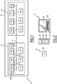
- An energy management installation 10 is represented on the figure 1 .
- Such an installation 10 is an electrical installation.
- the installation 10 comprises a set of members 12, a communication network 13, a power transmission network 14, a set of processing modules 15 and a computer program product 16.
- the computer program product is illustrated on the figure 2 .
- Each member 12 has a nature N, a state and a set of indicators relating to the operation of the member 12.
- each member 12 is chosen from the group comprising: an energy production member, a power consumption member and an energy storage member.
- the installation 10 comprises at least one power generation member 12, at least one energy consumption member 12 and at least one energy storage member 12.
- the installation 10 comprises six members 12: five energy consuming members 12A, 12B, 12C, 12D, 12E, five energy generating members 12F, 12G, 12H, 12I, 12J and two storage members 12K energy, 12L.
- a member 12 for producing energy is an organ capable of producing energy.
- An organ 12 of energy production is, for example, a hydroelectric dam, a hydroelectric power station, a nuclear power plant, a coal power station, an oil power station, a gas thermal power station, a generator, a wind turbine, a panel solar energy or a biomass steam turbine.
- a member 12 of energy consumption is a clean member to consume energy.
- a member 12 of energy consumption is, for example, an electrical lighting network, an electrical heating network or operational equipment.
- An energy storage member 12 is a member suitable for storing energy.
- An energy storage member 12 is, for example, an electrical energy accumulator such as a battery.
- An energy storage member 12 is both a generator of energy during its discharge and a consumer of energy during its charging.
- Each member 12 operates in two states: a first state for which the member 12 is on and a second state for which the member 12 is stopped.
- first state for which the member 12 is on
- second state for which the member 12 is stopped.
- the member 12 is in operation and is capable, according to the nature N of the member 12, to produce and / or consume energy.
- the member 12 is in the second state, the member 12 is unable to produce or consume energy.
- the indicators relating to the operation of each member 12 comprise information on the consumption and / or the energy production of the member 12.
- the indicators of the members 12 are described later.
- the communication network 13 is connected to each member 12 and to each processing module 15. Each member 12 is able to transmit data on the communication network 13 to at least one member 12 and to each processing module 15.
- the connection between each member 12 and the communication network 13 is, for example, established by wire connection or by radio link.
- the communication network 13 is, for example, a data bus.
- a data bus is a communication system shared between several components of a digital system for transferring data between system components.
- Each member 12 is adapted to be connected to or disconnected from the energy transport network 14.
- the energy transport network 14 is configured, on the one hand, to receive the energy produced by the energy production or energy storage members 12 connected to said energy transport network 14.
- the energy transport network 14 is able to distribute the energy received to the energy consumption or energy storage members 12 connected to said energy transport network 14.
- connection between each member 12 and the energy transport network 14 is, for example, established by a "machine to machine” protocol.
- the energy transport network 14 is divided into at least two sub-networks so that each sub-network gathers at least one member 12.
- the members 12 belonging to the same sub-network are, for example, defined by an operator during the initial configuration of the installation 10.
- the energy transport network 14 comprises two sub-networks 17 and 18.
- the energy consuming devices 12A, 12B, 12C, 12F, 12G energy generation and 12K energy storage belong to a first sub-network 17 of the energy transmission network 14.
- the energy consumption organs 12D, 12E, energy production 12H, 12I, 12J and energy storage 12L belong to a second sub-network 18 of the transmission network 14.
- each processing module 15 is connected to the communication network 13 and to the energy transport network 14.
- Each processing module 15 is preferably a computer.
- each processing module 15 is an electronic calculator adapted to manipulate and / or transform data represented as electronic or physical quantities in registers of the processing module 15 and / or memories in other similar data corresponding to physical data in memories, registers or other types of display, transmission or storage device.
- each processing module 15 comprises a processor 24 comprising a data processing unit 26, memories 28 and an information carrier reader 30.
- Each processing module 15 also comprises a keyboard 32 and a display unit 34.
- the computer program product 16 includes an information carrier 40.
- the information carrier 40 is a readable medium.
- An information carrier 40 is a support readable by each processing module 15, usually by each data processing unit 26.
- the information carrier 40 is a medium adapted to memorize electronic instructions and capable of being coupled to a data processing unit. bus of a computer system.
- the information carrier 40 is a diskette or floppy disk (" floppy disc "), an optical disk, a CD-ROM a magneto-optical disk, a ROM memory, a memory RAM, an EPROM memory, an EEPROM memory, a magnetic card or an optical card.
- On the information carrier 40 is stored a computer program including program instructions.
- the computer program is loadable on each data processing unit 26 and is adapted to be used to carry out the implementation of the energy management method when the computer program is implemented on each processing module 15.
- each processing module 15 interacting with the computer program product 16 is now described with reference to the figure 4 which schematically illustrates an example of implementation of the energy management method.
- the management method comprises a step 100 of providing the nature N of the operation of each member 12 in the first state. Indeed, only the members 12 in the first state are able to communicate data via the communication network 13.
- each member 12 in the first state transmits, via the communication network 13, to at least one other member 12 and to each processing module 15, the nature N of the member 12.
- the method comprises a step 110 of providing a first indicator I1 relating to an operating priority of each member 12 in the first state.
- the first indicator I1 is, for each member 12, relating to a nominal cost acceptable by each member 12.
- the cost is defined, for example, by a priority scale taking integer values understood in the broad sense between 1 and 10.
- a value of 10 on the priority scale designating a highly desired priority of purchasing energy for a consumer and a non-priority desire to sell energy for a producer.
- a value of 1 on the priority scale denoting a non-priority energy purchase wish for a consumer and a high priority energy sales desire for a producer.
- the cost is defined by a scale of decimal values ranging from zero to infinity.
- the cost is defined in units of liters of fuel per kilowatt-hour produced (L / kW.h), in units of euros per kilowatt-hour produced ( € / kW.h), or in units of dollars per kilowatt-hour produced ($ /kW.h).
- the first indicator I1 is the minimum cost of selling energy.
- a minimal cost is understood as the desire of a production or storage organ 12 to sell the energy produced.
- the lower the minimum cost the more the production or storage organ 12 wishes to sell the energy produced.
- the first indicator I1 is the maximum cost of purchasing energy.
- a maximum cost is understood as the desire of a consumer or storage organ 12 to buy energy.
- the lower the maximum cost the more the consumption or storage organ 12 wishes to buy energy.
- the method comprises a step 120 of providing a second indicator I2 relating to a nominal operating energy volume of each member 12 in the first state.
- the nominal operating energy volume of a member 12 is the volume usually required by the member 12 to operate under optimum conditions.
- the second indicator I2 is, for example, expressed in kilowatt hours (kW.h).
- the second indicator I2 is the volume of energy desired for sale.
- the organ 12 has a volume of energy that it wishes to sell at least at the minimum cost of energy sale fixed by the first indicator I1 of the organ 12.
- the second indicator I2 is the volume of energy desired at the time of purchase.
- the organ 12 wishes to buy a given volume of energy at most at the maximum cost of purchasing energy fixed by the first indicator I1 of the organ 12.
- the method further comprises providing the first indicator I1 and the second indicator I2 of each sub-organ.
- At least the value of the first indicator I1 of a sub-organ is different from the value of the first indicator I1 of the other sub-organ of the same organ and / or at least the value of the second indicator I2 of a sub-organ is different from the value of the second indicator I2 of the other sub-organ of the same organ.
- the second indicator I2 of one of the sub-organs of the member 12 is the minimum volume of energy desired at the sale regardless of the value of the first indicator I1 of the sub-organ.
- the first indicator I1 takes a minimum value
- the second indicator I2 takes a value relative to the volume of critical energy that wants to sell, regardless of the selling price, the organ.
- the energy production unit 12 is ready to sell "at a loss", ie to sell at a price even lower than the "market price".
- the second indicator I2 of one of the sub-organs of the member 12 is the minimum volume of energy desired at purchase regardless of the value of the first indicator I1 of the sub-body.
- the first indicator I1 takes a maximum value
- the second indicator I2 takes a value relative to the volume of critical energy that wants to buy, regardless of the purchase price, the organ 12.
- the consumer organ 12 is ready to buy energy at a price even higher than the "market price".
- the market price is the price of a good determined by the law of supply and demand in the market economy regimes. This notion will be developed later in the description.
- the critical energy operating volume of an organ is the minimum volume necessary to provide the vital functions of the organ.
- the consumer member 12A comprises two sub-parts 12A_1 and 12A_2 illustrated on the figure 1 .
- the energy storage members 12 do not include sub-organs since such members 12 serve as a buffer to ensure the production or consumption of energy at critical moments when consumption is high and production is low or vice versa.
- the first sub-member of each member 12 has a first indicator I1 and a second indicator I2 identical respectively to the first indicator I1 and the second indicator I2 of the corresponding member 12.
- the second sub-organ of each organ 12 has a first indicator I1 of minimum value, respectively maximum on the priority scale and a second indicator I2 relating to the minimum volume of energy desired for sale, respectively at the time of purchase. function of the nature N of the corresponding organ 12. Therefore, the first indicator I1 of the second sub-organ is less than or equal to the first indicator I1 of the first sub-organ of the same organ 12. In fact, the volume of critical energy can not be greater than the strict sense of the volume. nominal energy.
- the indicators I1, I2 of each member 12 are, for example, calculated by each member 12 as a function of at least one characteristic selected from the group comprising: the time of day, the time of year, the weather, the the energy requirements of the organ 12, the energy autonomy of the organ 12, the capacity of the organ 12 to produce energy, the shutdown or the operation of the organ 12, experience on the functioning of the organ 12, the failures of the organ 12 or an anticipation of the energy requirement of the organ 12.
- the values of the indicators I1, I2 are set by one or more operators.
- the members 12 belonging to the first sub-network 17 illustrated in FIG. figure 1 provide via the communication network 13, the data listed in Table 1: Table 1 organs Nature N First indicator I1 Second indicator I2 12A_1 Consumer (hospital) 8 500 kW.h 12A_2 10 100 kW.h 12B Consumer (lighting a home) 5 200 kW.h 12C Consumer (lighting a football stadium) 3 300 kW.h 12F Producer (wind turbine) 1 500 kW.h 12G Producer (solar panel) 2 200 kW.h 12K Storage (landfill) 10 100 kW.h Storage (in charge) 1 50 kW.h
- the consuming organ 12A which is a hospital has a priority energy requirement since the first indicator I1 of the first sub-organ 12A_1 is relatively high on the priority scale.
- the consumer unit 12A is therefore ready to put a significant cost to be supplied with energy, which results in a value of 8 on the priority scale.
- the consumption member 12A also has a critical energy requirement indicated by the values of the first indicator I1 and the second indicator I2 of the second sub-member 12A_2 of the consumption member 12A. To meet this critical need, the consumer unit 12A is ready to buy energy from a producer or a reservoir regardless of the cost of energy, which translates into a maximum value of the first indicator I1.
- Consumer unit 12B which is the lighting system of a home, has a lower energy need than the hospital, which translates into a value of 5 on the priority scale.
- the consumer organization 12B therefore wants to pay a lower cost to be supplied with energy and prefers to take the risk of not being supplied with energy rather than paying a higher cost.
- the value of the first indicator I1 of the consumption member 12C translates a need even less priority energy than the consumption member 12B.
- the production organ 12F which is a wind turbine wishes to sell its energy production in priority because such a production is renewable. This translates to a value of 1 on the priority scale.
- the energy produced is called "low cost”.
- the storage member 12K which is a battery for use in an emergency has two pairs of first and second indicators I1, I2.
- the first pair of first and second indicators I1, I2 reflects the discharge of the storage organ 12K during which the storage member 12K operates as a production unit.
- the second pair of first and second indicators I1, I2 reflects the load of the storage member 12K in which the storage member 12K functions as a consumer member.
- the storage member 12K When the storage member 12K functions as a production unit, the storage member 12K wishes to sell its energy production at a higher cost than the production units 12F and 12G since the function of an emergency battery is to supply power to the energy transport network 14 only during over-consumption on the network 20. This results in a value of 10 on the priority scale.
- the energy that the 12K storage unit wants to sell is therefore relatively the most expensive on the market and therefore the least likely to be sold.
- the storage member 12K When the storage member 12K functions as a consumption member, the storage member 12K wishes to buy energy at a lower cost than the consumer units 12A and 12B since the function of an emergency battery is to consume the energy of the energy transport network 14 only during an under-consumption on the transport network 14. This results in a value of 1 on the priority scale.
- the energy that wants to buy the 12K storage device is relatively the least expensive of the market and therefore the least likely to be purchased.
- the storage members 12 are used to regulate the consumption and production peaks on the transmission network 14, that is to say to smooth dynamically the jolts and gaps between the consumption and the production of electricity. 'energy.
- the storage members 12 display first indicators I1 of median value, for example equal to 5.
- the method then comprises a step 130 for determining, for each member 12, a global indicator IG from the nature N, the first indicator I1 and the second indicator I2 provided.
- the global indicator IG of each organ 12 includes all the criteria useful for the purchase and / or sale of energy by each organ 12.
- the global indicator IG is a quintuplet of coordinates whose first coordinate is the nature N of the organ 12, the second coordinate is the first indicator I1 of the first sub-organ of the organ 12 , the third coordinate is the second indicator I2 of the first sub-organ of the organ 12, the fourth coordinate is the first indicator I1 of the second sub-organ of the organ 12 and the fifth coordinate is the second indicator I2 of the second sub -organ organ 12.
- the first coordinate takes, for example, the value 1 for a member 12 of energy consumption, the value 2 for a member 12 of energy production and the value 3 for a member 12 of energy storage.
- the second and fourth coordinates are expressed, for example, in cost units defined in the priority scale described above.
- the third and fifth coordinates are expressed, for example, in kilowatt hours.
- the global indicator IG of the consumer unit 12A is the quintuplet (1; 8; 500; 10; 500).
- the value of the first indicator I1 of the organ 12 is inscribed in the second coordinate
- the value of the second indicator I2 of the organ 12 is inscribed in the third coordinate
- the fourth and fifth coordinates are set to zero.
- the global indicator IG of the production unit 12F is the quintuplet (2; 1; 500; 0; 0).
- the value of the first indicator I1 of the member 12 in energy-consuming operation is inscribed in the second coordinate
- the value of the second indicator I2 in energy-consuming operation is written in the third coordinate
- the value of the first indicator I1 of the organ 12 in energy generating operation is entered in the fourth coordinate
- the value of the second indicator I2 in energy generating operation is entered in the fifth coordinate.
- the global indicator IG of the storage device 12K is the quintuplet (3; 10; 100; 1; 50).
- the method comprises a step 140 for calculating a first average indicator I1_M from at least one global indicator IG of a production member 12 and at least one global indicator IG of a consumer member 12 .
- the calculation of the first average indicator I1_M follows a law of supply and demand.
- the law of supply and demand represents the main model of the market economy and is based on the balance between the quantity of a certain good offered and the demand for such a good.
- the quantity of a good varies according to the importance of supply and demand.
- the supply exceeds the demand for a good, the price of the good will decrease until there is a balance between the quantity of good produced and the price of the good.
- the lower the price of a good the more willing he is to buy the good.
- the higher the price of the good the more willing he is to sell the good.
- the first average indicator I1_M is a cost of the same unit as the first indicator I1 for which the quantities of energy desired for purchase by the consumers are equal to the quantities of energy desired for sale by the producers.
- the first average indicator I1_M is also called "market price”.
- the calculation of the first indicator I1 comprises a first phase of compensation of the volumes desired for purchase by the consumer units 12 with the volumes desired for sale by the production units 12, as long as the first indicator I1 of the consumer unit 12 whose first indicator I1 is the highest, among the consumer units 12 whose purchase volume is not compensated, is greater than or equal to the first indicator I1 of the production unit 12 whose first indicator I1 is the lowest, among the production units 12 whose volume for sale is not compensated.
- the volumes are given by the second indicators I2 of each organ 12.
- the first indicator I1 of the consumer organ 12 whose first indicator I1 is the highest is strictly lower than the first indicator I1 of the production organ 12 whose first indicator I1 is the lowest, the first indicator I1 of the consumer unit is called the “consumer threshold” and the first indicator I1 of the production organ 12 is called the “producer threshold”.
- the last consumer unit 12 whose second indicator I2 is compensated is called “last consumer” and the last production member 12 whose second indicator I2 is compensated is called “last producer”.
- the calculation of the first indicator I1 comprises a second phase of calculating the average between the consumer threshold and the producer threshold.
- the first average indicator I1_M is equal to the first indicator I1 of the last consumer.
- the first average indicator I1_M is equal to the first indicator I1 of the last producer. Otherwise, the first average indicator I1_M is equal to the calculated average.
- the first average indicator I1_M thus takes into account the completeness of the coordinates of the global indicator IG, that is to say the nature N of the organs 12, the first indicator I1 of the organs 12 and the second indicator or indicators I2 of organs 12.
- the first indicator I1 that is to say the purchase price, of value 3 of the consumer unit 12C is therefore the consumer threshold.
- the first indicator I1, that is to say the selling price, of value 10 of the production unit 12F is the producer threshold.
- the consumer unit 12B is the last consumer and the production unit 12E is the last producer.
- the calculated average is equal to 6.5.
- the calculated average being strictly greater than the first indicator I1 of the consumption member 12B, the first average indicator I1_M is equal to the value of the first indicator I1 of the consumption member 12B, that is to say is equal to 5.
- the method then comprises a step 150 for comparing, for each member 12, the first indicator I1 with the first average indicator I1_M.
- a comparison amounts to comparing the purchase cost for a consumer unit 12 or the cost of sale for a production unit 12 at the market price.
- the result of the comparison is said to be "higher” and is denoted “+” when the first indicator I1 is strictly greater than the first average indicator I1_M.
- the result of the comparison is said to be “lower” and is denoted "-" when the first indicator I1 is strictly lower than the first average indicator I1_M.
- the method comprises a step 160 of connection or disconnection of each member 12 to the energy transport network 14 as a function of the comparison results and the nature N of each member 12.
- the member 12 When the member 12 is a production member or a storage member, the member 12 is connected to the energy transport network 14 if the first indicator I1 of the member 12 is less than or equal to the first average indicator I1_M. So, in the example of figures 1 and 3 the production units 12F and 12G are connected to the transport network 14. The production devices 12 connected to the transport network 14 are therefore the organs selling their energy from a cost less than or equal to the market price.
- the member 12 When the member 12 is a consumption member or a storage member, the member 12 is connected to the energy transport network 14 if the first indicator I1 of the member 12 is greater than or equal to the first average indicator I1_M. So, in the example of figures 1 and 3 , the consumption organs 12A and 12B are connected to the transport network 14. The consumption organs 12 connected to the transport network 14 are therefore the organs whose purchase cost of energy is greater than or equal to the market price.
- the member 12 When the member 12 is a production member or a storage member, the member 12 is disconnected from the energy transmission network 14 if the first indicator I1 of the member 12 is strictly greater than the first average indicator I1_M . So, in the example of figures 1 and 3 the storage member 12K is disconnected from the transport network 14. The production units 12 disconnected from the transport network 14 are therefore the organs selling their energy from a cost strictly greater than the market price.
- the member 12 When the member 12 is a consumption member or a storage member, the member 12 is disconnected from the energy transport network 14 if the first indicator I1 of the member 12 is less strictly than the first average indicator I1_M . So, in the example of figures 1 and 3 the consumption member 12C is disconnected from the transport network 14. The consumption organs 12 disconnected from the transport network 14 are therefore the organs whose energy purchase cost is strictly lower than the market price.
- each member 12 of the installation 10 is able to connect or disconnect from the transport network 14 independently.
- Each member 12 has its own reaction rate, particularly in terms of hysteresis and time constant. reaction which is adjusted by each member 12 to avoid oscillations and stabilize the state of the transport network 14.
- the steps of the method are iterated at each change of an indicator of at least one member 12 or at each change in the status of an organ 12.
- the iteration of the steps of the method is represented on the figure 4 by the arrow 170.
- the management method makes it possible to adapt the production of energy to the consumption of energy.
- the production devices 12 therefore operate at the optimum of their efficiency and are disconnected from the energy transport network 14 when such bodies are not solicited by the consumer bodies 12.
- the balance between the consumption and the production of energy is achieved by self-convergence between bid prices and energy demand prices.
- the method makes it possible to assign a priority to a producer or a consumer, such a method is adapted to supply primarily consumers with a crucial need for energy, the hospital in the previous example.
- such a method also makes it possible to promote the use of renewable energy sources in relation to non-renewable energy sources by assigning a higher priority to renewable sources, for example by assigning them a first low-value indicator I1. which amounts to selling them at low cost.
- the process is capable of reducing the consumption of non-renewable energies.
- the transport network 14 Since the energy transport network 14 is divided into sub-networks 17, 18, each comprising a processing module 15, the transport network 14 is more robust. Indeed, a destruction of a part of the transport network 14 or a malfunction of the production members 12 of a sub-network does not affect the operation of the other sub-networks.
- each module processing 15 provides access to the history of energy exchanges on the transport network 14 and the current state of the network.
- it is possible to have access at any time and anywhere in the transport network 14 to the history and information concerning all the members 12 connected to the transport network 14.
- the installation 10 is resilient, that is to say that such an installation continues to operate even in case of failure. Because of its robustness and resilience, such an installation 10 is particularly suitable for serving isolated or underserved sites such as islands, entrenched camps or sites on which the public network is uncertain.
- the installation 10 is easy to use. Indeed, such an installation is, for example, configured with a "plug and play” procedure (English expression translated into “logs in and plays”), that is to say, a procedure for devices of a system to be recognized quickly and automatically by an operating system as soon as the system is connected and without restarting the operating system.
- a "plug and play” procedure English expression translated into “logs in and plays”
- each member 12 facilitates the implementation of the method and in particular to reduce the computing power for carrying out the method.
- each organ 12 has an identification system for raising an alert or receiving an order from a supervisor.
- a supervisor is optionally usable for sending orders to the various organs for adjusting consumption and energy production.
- each energy production unit 12 communicates via the communication network 13, an additional indicator relating to the distance in absolute value between the current operating point of the member 12 and the optimum operating point of the 12.
- the operating point is, for example, expressed in liters of fuel per kilowatt-hour produced, in units of euros per kilowatt-hour produced, in units of dollars per kilowatt-hour produced, or in percentages (%).
- the current operating point corresponds to the current operation of the member 12.
- the optimum operating point corresponds to the optimal operation of the member 12.
- the additional indicator is equal to zero, the member 12 operates optimally.
- the additional indicator is greater than zero, the member 12 does not function optimally.
- the method then comprises charging or discharging energy into the transport network 14 by the energy storage members 12, until at least one or all of the power generating units 12 operate from optimally.
- Another variant consists, for example, in combining one or more examples described above.
Landscapes
- Engineering & Computer Science (AREA)
- Power Engineering (AREA)
- Supply And Distribution Of Alternating Current (AREA)
- Management, Administration, Business Operations System, And Electronic Commerce (AREA)
Description
La présente invention concerne un procédé de gestion d'énergie entre des organes. La présente invention se rapporte aussi à un produit programme d'ordinateur et à un support d'informations associé. La présente invention concerne aussi une installation de gestion propre à mettre en oeuvre le procédé de gestion.The present invention relates to a method of energy management between organs. The present invention also relates to a computer program product and an associated information carrier. The present invention also relates to a management facility adapted to implement the management method.
Le document
Il est connu de l'état de la technique un système de production d'énergie propre à distribuer l'énergie produite à des consommateurs via un réseau de transport d'énergie.It is known from the state of the art a system of producing clean energy to distribute the energy produced to consumers via a transmission network.
Cependant, un tel système d'énergie est surdimensionné pour prendre en compte tous les pics de consommation envisageables et fonctionne donc dans des conditions non-optimales.However, such an energy system is oversized to take into account all conceivable consumption peaks and therefore operates under non-optimal conditions.
Il existe donc un besoin pour un procédé de gestion d'énergie permettant d'adapter la production d'énergie à la consommation d'énergie.There is therefore a need for a method of energy management for adapting energy production to energy consumption.
A cet effet, l'invention a pour objet un procédé de gestion d'énergie dans une installation électrique, l'installation comprenant :
- au moins un organe de consommation d'énergie électrique,
- au moins un organe de production d'énergie électrique,
- au moins un organe de stockage d'énergie électrique,
- un réseau de transport d'énergie, chaque organe étant propre à être connecté ou déconnecté du réseau de transport d'énergie, le réseau de transport étant divisé en au moins deux sous-réseaux, chaque sous-réseau regroupant au moins un organe,
- un module de traitement pour chaque sous-réseau,
- un réseau de communication connecté à chaque organe et à chaque module de traitement, chaque organe étant propre à émettre des données sur le réseau de communication vers au moins un organe et vers chaque module de traitement,
- fourniture de la nature du fonctionnement de chaque organe, la nature du fonctionnement de chaque organe étant choisie dans le groupe comprenant : un organe de production d'énergie, un organe de consommation d'énergie et un organe de stockage d'énergie,
- fourniture d'un premier indicateur relatif à une priorité de fonctionnement de chaque organe,
- fourniture d'un deuxième indicateur relatif à un volume d'énergie nominal de fonctionnement de chaque organe,
- détermination, pour chaque organe, d'un indicateur global à partir de la nature, du premier indicateur et du deuxième indicateur fournis,
- calcul d'un premier indicateur moyen à partir d'au moins un indicateur global d'un organe de production et d'au moins un indicateur global d'un organe de consommation,
- comparaison, pour chaque organe, du premier indicateur au premier indicateur moyen, et
- connexion ou déconnexion de chaque organe au réseau de transport d'énergie en fonction de la comparaison et de la nature de chaque organe.
- at least one electrical energy consumption member,
- at least one electrical power generating member,
- at least one electrical energy storage member,
- a power transmission network, each member being able to be connected or disconnected from the power transmission network, the transport network being divided into at least two sub-networks, each sub-network comprising at least one member,
- a processing module for each sub-network,
- a communication network connected to each member and to each processing module, each member being able to transmit data on the communication network to at least one member and to each processing module,
- providing the nature of the operation of each member, the nature of the operation of each member being selected from the group comprising: a power generating member, a power consumption member and an energy storage member,
- providing a first indicator relating to an operating priority of each organ,
- providing a second indicator relating to a nominal operating energy volume of each member,
- determination, for each organ, of a global indicator based on the nature, the first indicator and the second indicator provided,
- calculating a first average indicator from at least one global indicator of an organ of production and at least one global indicator of an organ of consumption,
- comparing, for each organ, the first indicator with the first average indicator, and
- connection or disconnection of each organ to the energy transport network according to the comparison and the nature of each organ.
Suivant des modes de réalisation particuliers, le procédé comprend une ou plusieurs des caractéristiques suivantes, prises isolément ou suivant toutes les combinaisons techniquement possibles :
- lorsque l'organe est un organe de production ou un organe de stockage, le premier indicateur est le coût minimal de vente d'énergie, et
- lorsque l'organe est un organe de consommation ou un organe de stockage, le premier indicateur est le coût maximal d'achat d'énergie.
- lorsque l'organe est un organe de production ou un organe de stockage, le deuxième indicateur est le volume d'énergie souhaité à la vente, et
- lorsque l'organe est un organe de consommation ou un organe de stockage, le deuxième indicateur est le volume d'énergie souhaité à l'achat.
- au moins un organe, parmi les organes de consommation et les organes de production, comprend deux sous-organes, le procédé comprenant, en outre, la fourniture du premier indicateur et du deuxième indicateur de chaque sous-organe, au moins la valeur du premier indicateur d'un sous-organe étant différente de la valeur du premier indicateur de l'autre sous-organe du même organe et/ou au moins la valeur du deuxième indicateur d'un sous-organe étant différente de la valeur du deuxième indicateur de l'autre sous-organe du même organe.
- pour chaque organe comprenant deux sous-organes,
- lorsque l'organe est un organe de production ou un organe de stockage, le deuxième indicateur de l'un des sous-organes de l'organe est le volume minimal d'énergie souhaité à la vente, et
- lorsque l'organe est un organe de consommation ou un organe de stockage, le deuxième indicateur de l'un des sous-organes de l'organe est le volume minimal d'énergie souhaité à l'achat.
- les indicateurs fournis pour chaque organe dépendent d'au moins une caractéristique choisie dans le groupe comprenant : l'heure du jour, la période de l'année, la météo, les besoins opérationnels en énergie de l'organe, l'autonomie en énergie de l'organe, la capacité de l'organe à produire de l'énergie, l'arrêt ou le fonctionnement de l'organe, les retours d'expérience sur le fonctionnement de l'organe, les défaillances de l'organe et une anticipation des besoins énergétiques de l'organe.
- lorsque l'organe est un organe de production ou un organe de stockage, l'organe est connecté au réseau de transport d'énergie si le premier indicateur de l'organe est inférieur ou égal au premier indicateur moyen, et
- lorsque l'organe est un organe de consommation ou un organe de stockage, l'organe est connecté au réseau de transport d'énergie si le premier indicateur de l'organe est supérieur ou égal au premier indicateur moyen.
- lorsque l'organe est un organe de production ou un organe de stockage, l'organe est déconnecté du réseau de transport d'énergie si le premier indicateur de l'organe est supérieur au sens strict au premier indicateur moyen, et
- lorsque l'organe est un organe de consommation ou un organe de stockage, l'organe est déconnecté du réseau de transport d'énergie si le premier indicateur de l'organe est inférieur au sens strict au premier indicateur moyen.
- when the organ is an organ of production or a storage organ, the first indicator is the minimum cost of selling energy, and
- when the organ is a consumer body or a storage organ, the first indicator is the maximum cost of purchasing energy.
- when the organ is an organ of production or a storage organ, the second indicator is the volume of energy desired for sale, and
- when the organ is a consumer body or a storage organ, the second indicator is the volume of energy desired at the time of purchase.
- at least one organ, among the consumer organs and the production members, comprises two sub-organs, the method further comprising providing the first indicator and the second indicator of each sub-organ, at least the value of the first an indicator of a sub-organ being different from the value of the first indicator of the other sub-organ of the same organ and / or at least the value of the second indicator of a sub-organ being different from the value of the second indicator of the other sub-organ of the same organ.
- for each organ comprising two sub-organs,
- when the organ is an organ of production or a storage organ, the second indicator of one of the sub-organs of the organ is the minimum volume of energy desired for sale, and
- when the organ is a consumer organ or a storage organ, the second indicator of one of the sub-organs of the organ is the minimum volume of energy desired at the time of purchase.
- the indicators provided for each organ depend on at least one characteristic selected from the group comprising: the time of day, the time of year, the weather, the operational energy requirements of the organ, the energy autonomy of the organ, the ability of the organ to produce energy, the stopping or operation of the organ, the feedback on the functioning of the organ, the failures of the organ and an anticipation of the energy needs of the organ.
- when the member is a production member or a storage member, the member is connected to the energy transport network if the first indicator of the member is less than or equal to the first average indicator, and
- when the member is a consumption member or a storage member, the member is connected to the energy transport network if the first indicator of the member is greater than or equal to the first average indicator.
- when the organ is a production organ or a storage organ, the organ is disconnected from the energy transport network if the first indicator of the organ is strictly greater than the first average indicator, and
- when the member is a consumer member or a storage member, the member is disconnected from the energy transport network if the first indicator of the organ is less strictly than the first average indicator.
L'invention concerne également un produit programme d'ordinateur comprenant des instructions logicielles, les instructions logicielles mettant en oeuvre un procédé tel que décrit précédemment, lorsque les instructions logicielles sont exécutées par un ordinateur.The invention also relates to a computer program product comprising software instructions, the software instructions implementing a method as described above, when the software instructions are executed by a computer.
L'invention a aussi pour objet un support d'informations sur lequel est mémorisé un produit programme d'ordinateur tel que décrit ci-dessus.The invention also relates to an information carrier on which is stored a computer program product as described above.
L'invention se rapporte également à une installation électrique de gestion d'énergie comprenant :
- au moins un organe de consommation d'énergie électrique,
- au moins un organe de production d'énergie électrique,
- au moins un organe de stockage d'énergie électrique,
- un réseau de transport d'énergie, chaque organe étant propre à être connecté ou déconnecté du réseau de transport d'énergie, le réseau de transport étant divisé en au moins deux sous-réseaux, chaque sous-réseau regroupant au moins un organe,
- un module de traitement pour chaque sous-réseau,
- un réseau de communication connecté à chaque organe et à chaque module de traitement, chaque organe étant propre à émettre des données sur le réseau de communication vers au moins un organe et vers chaque module de traitement,
- chaque module de traitement étant configuré pour :
- recevoir la nature du fonctionnement de chaque organe, la nature du fonctionnement de chaque organe étant choisie dans le groupe comprenant : un organe de production d'énergie, un organe de consommation d'énergie et un organe de stockage d'énergie,
- recevoir un premier indicateur relatif à une priorité de fonctionnement de chaque organe,
- recevoir un deuxième indicateur relatif à un volume d'énergie nominal de fonctionnement de chaque organe,
- déterminer, pour chaque organe, un indicateur global à partir de la nature, du premier indicateur et du deuxième indicateur fournis,
- calculer un premier indicateur moyen à partir d'au moins un indicateur global d'un organe de production et d'au moins un indicateur global d'un organe de consommation,
- comparer, pour chaque organe, le premier indicateur au premier indicateur moyen, et
- connecter ou déconnecter chaque organe au réseau de transport d'énergie en fonction de la comparaison et de la nature de chaque organe.
- at least one electrical energy consumption member,
- at least one electrical power generating member,
- at least one electrical energy storage member,
- a power transmission network, each member being able to be connected or disconnected from the power transmission network, the transport network being divided into at least two sub-networks, each sub-network comprising at least one member,
- a processing module for each sub-network,
- a communication network connected to each member and to each processing module, each member being able to transmit data on the communication network to at least one member and to each processing module,
- each processing module being configured for:
- receive the nature of the operation of each organ, the nature of the functioning of each organ being chosen from the group comprising: an energy generating member, a power consuming member and an energy storage member,
- receive a first indicator relating to an operating priority of each organ,
- receive a second indicator relating to a nominal energy volume of operation of each organ,
- determine, for each organ, a global indicator based on the nature, the first indicator and the second indicator provided,
- calculate a first average indicator from at least one global indicator of an organ of production and at least one global indicator of an organ of consumption,
- comparing, for each organ, the first indicator with the first average indicator, and
- connect or disconnect each organ to the energy transmission network according to the comparison and the nature of each organ.
L'invention a, également, pour objet un procédé selon la revendication 1.The invention also relates to a method according to
Suivant des modes de réalisation particuliers, le procédé comprend une ou plusieurs des caractéristiques des revendications 2 à 8, prises isolément ou suivant toutes les combinaisons techniquement possibles.According to particular embodiments, the method comprises one or more of the features of
L'invention porte aussi sur un produit programme d'ordinateur selon la revendication 9.The invention also relates to a computer program product according to
L'invention concerne, en outre, un support d'informations selon la revendication 10.The invention further relates to an information carrier according to
L'invention concerne, également, une installation selon la revendication 11.The invention also relates to an installation according to claim 11.
D'autres caractéristiques et avantages de l'invention apparaîtront à la lecture de la description qui suit de modes de réalisation de l'invention, donnée à titre d'exemple uniquement et en référence aux dessins qui sont :
-
figure 1 , une vue schématique d'un exemple d'une installation de gestion d'énergie, -
figure 2 , une vue schématique d'un exemple d'un module de traitement et d'un produit programme d'ordinateur de l'installation de lafigure 1 , -
figure 3 , un exemple de détermination d'un premier indicateur moyen suivant une loi de l'offre et de la demande, et -
figure 4 , un ordinogramme d'un exemple de mise en oeuvre d'un procédé de gestion d'énergie.
-
figure 1 , a schematic view of an example of an energy management installation, -
figure 2 , a schematic view of an example of a processing module and a computer program product of the installation of thefigure 1 , -
figure 3 , an example of determining a first average indicator according to a law of supply and demand, and -
figure 4 , a flowchart of an exemplary implementation of a power management method.
Une installation 10 de gestion d'énergie est représentée sur la
L'installation 10 comprend un ensemble d'organes 12, un réseau de communication 13, un réseau de transport d'énergie 14, un ensemble de modules de traitement 15 et un produit programme d'ordinateur 16. Le produit programme d'ordinateur est illustré sur la
Chaque organe 12 présente une nature N, un état et un ensemble d'indicateurs relatifs au fonctionnement de l'organe 12.Each
La nature N de chaque organe 12 est choisie dans le groupe comprenant : un organe de production d'énergie, un organe de consommation d'énergie et un organe de stockage d'énergie.The nature N of each
L'installation 10 comprend au moins un organe 12 de production d'énergie, au moins un organe 12 de consommation d'énergie et au moins un organe 12 de stockage d'énergie.The
Dans le mode de réalisation illustré sur la
Un organe 12 de production d'énergie est un organe propre à produire de l'énergie. Un organe 12 de production d'énergie est, par exemple, un barrage hydroélectrique, une centrale hydroélectrique, une centrale nucléaire, une centrale au charbon, une centrale au fioul, une centrale thermique au gaz, un groupe électrogène, une éolienne, un panneau solaire ou encore une turbine à vapeur biomasse.A
Un organe 12 de consommation d'énergie est un organe propre à consommer de l'énergie. Un organe 12 de consommation d'énergie est, par exemple, un réseau électrique d'éclairage, un réseau électrique de chauffage ou encore un équipement opérationnel.A
Un organe 12 de stockage d'énergie est un organe propre à stocker de l'énergie. Un organe 12 de stockage d'énergie est, par exemple, un accumulateur d'énergie électrique tel qu'une batterie. Un organe 12 de stockage d'énergie est à la fois un producteur d'énergie lors de sa décharge et un consommateur d'énergie lors de sa charge.An
Chaque organe 12 fonctionne selon deux états : un premier état pour lequel l'organe 12 est en marche et un deuxième état pour lequel l'organe 12 est à l'arrêt. Lorsque l'organe 12 est dans le premier état, l'organe 12 est en marche et est donc capable, selon la nature N de l'organe 12, de produire et/ou de consommer de l'énergie. Lorsque l'organe 12 est dans le deuxième état, l'organe 12 n'est capable ni de produire, ni de consommer de l'énergie.Each
Les indicateurs relatifs au fonctionnement de chaque organe 12 comportent des informations sur la consommation et/ou la production d'énergie de l'organe 12. Les indicateurs des organes 12 sont décrits ultérieurement.The indicators relating to the operation of each
Le réseau de communication 13 est connecté à chaque organe 12 et à chaque module de traitement 15. Chaque organe 12 est propre à émettre des données sur le réseau de communication 13 vers au moins un organe 12 et vers chaque module de traitement 15. La connexion entre chaque organe 12 et le réseau de communication 13 est, par exemple, établie par liaison filaire ou par liaison hertzienne.The
Le réseau de communication 13 est, par exemple, un bus de données. Un bus de données est un système de communication partagé entre plusieurs composants d'un système numérique et destiné au transfert des données entre les composants du système.The
Chaque organe 12 est propre à être connecté ou déconnecté du réseau de transport d'énergie 14.Each
Le réseau de transport d'énergie 14 est configuré, d'une part, pour recevoir l'énergie produite par les organes 12 de production d'énergie ou de stockage d'énergie connectés audit réseau de transport d'énergie 14.The
D'autre part, le réseau de transport d'énergie 14 est propre à distribuer l'énergie reçue aux organes 12 de consommation d'énergie ou de stockage d'énergie connectés audit réseau de transport d'énergie 14.On the other hand, the
La connexion entre chaque organe 12 et le réseau de transport d'énergie 14 est, par exemple, établi par un protocole « machine to machine » (de l'anglais « communication de machine à machine »).The connection between each
Le réseau de transport d'énergie 14 est divisé en au moins deux sous-réseaux de sorte que chaque sous-réseau regroupe au moins un organe 12.The
Les organes 12 appartenant à un même sous-réseau sont, par exemple, définis par un opérateur lors de la configuration initiale de l'installation 10.The
Dans le mode de réalisation illustré en
L'interaction du produit programme d'ordinateur 16 avec chaque module de traitement 15 permet de mettre en oeuvre un procédé de gestion d'énergie entre les organes 12 de l'installation 10.The interaction of the
Pour cela, chaque module de traitement 15 est connecté au réseau de communication 13 et au réseau de transport d'énergie 14.For this, each
Chaque module de traitement 15 est, de préférence, un ordinateur.Each
Plus généralement, chaque module de traitement 15 est un calculateur électronique propre à manipuler et/ou transformer des données représentées comme des quantités électroniques ou physiques dans des registres du module de traitement 15 et/ou des mémoires en d'autres données similaires correspondant à des données physiques dans les mémoires, des registres ou d'autres types de dispositif d'affichage, de transmission ou de mémorisation.More generally, each
Comme illustré sur la
Le produit programme d'ordinateur 16 comporte un support d'informations 40.The
Le support d'informations 40 est un support lisible. Un support d'informations 40 est un support lisible par chaque module de traitement 15, usuellement par chaque unité de traitement de données 26. Le support d'informations 40 est un médium adapté à mémoriser des instructions électroniques et capable d'être couplé à un bus d'un système informatique.The
A titre d'exemple, le support d'informations 40 est une disquette ou disque souple (de la dénomination anglaise de « floppy disc »), un disque optique, un CD-ROM un disque magnéto-optique, une mémoire ROM, une mémoire RAM, une mémoire EPROM, une mémoire EEPROM, une carte magnétique ou une carte optique.For example, the
Sur le support d'informations 40 est mémorisé un programme d'ordinateur comprenant des instructions de programme.On the
Le programme d'ordinateur est chargeable sur chaque unité de traitement de données 26 et est adapté pour être entraîner la mise en oeuvre du procédé de gestion d'énergie lorsque le programme d'ordinateur est mis en oeuvre sur chaque module de traitement 15.The computer program is loadable on each
Le fonctionnement de chaque module de traitement 15 en interaction avec le produit programme d'ordinateur 16 est maintenant décrit en référence à la
Initialement, le procédé de gestion comporte une étape 100 de fourniture de la nature N du fonctionnement de chaque organe 12 dans le premier état. En effet, seuls les organes 12 dans le premier état sont propres à communiquer des données via le réseau de communication 13.Initially, the management method comprises a
Ainsi, chaque organe 12 dans le premier état transmet, via le réseau de communication 13, à au moins un autre organe 12 et à chaque module de traitement 15, la nature N de l'organe 12.Thus, each
Puis, le procédé comporte une étape 110 de fourniture d'un premier indicateur I1 relatif à une priorité de fonctionnement de chaque organe 12 dans le premier état.Then, the method comprises a
Le premier indicateur I1 est, pour chaque organe 12, relatif à un coût nominal acceptable par chaque organe 12.The first indicator I1 is, for each
Dans la suite de la description, le coût est défini, à titre d'exemple, par une échelle de priorité prenant des valeurs entières comprises au sens large entre 1 et 10. Une valeur de 10 sur l'échelle de priorité désignant un souhait hautement prioritaire d'achat d'énergie pour un consommateur et un souhait non prioritaire de vente d'énergie pour un producteur. Une valeur de 1 sur l'échelle de priorité désignant un souhait non prioritaire d'achat d'énergie pour un consommateur et un souhait hautement prioritaire de vente d'énergie pour un producteur.In the remainder of the description, the cost is defined, for example, by a priority scale taking integer values understood in the broad sense between 1 and 10. A value of 10 on the priority scale designating a highly desired priority of purchasing energy for a consumer and a non-priority desire to sell energy for a producer. A value of 1 on the priority scale denoting a non-priority energy purchase wish for a consumer and a high priority energy sales desire for a producer.
En variante, le coût est défini par une échelle de valeurs décimales allant de zéro à l'infini.Alternatively, the cost is defined by a scale of decimal values ranging from zero to infinity.
Encore en variante, le coût est défini en unité de litres de carburant par kilowattheure produit (L/kW.h), en unité d'euros par kilowattheure produit (€/kW.h) ou en unité de dollars par kilowattheure produit ($/kW.h).Alternatively, the cost is defined in units of liters of fuel per kilowatt-hour produced (L / kW.h), in units of euros per kilowatt-hour produced (€ / kW.h), or in units of dollars per kilowatt-hour produced ($ /kW.h).
Lorsque l'organe 12 est un organe de production ou un organe de stockage, le premier indicateur I1 est le coût minimal de vente d'énergie. Un tel coût minimal se comprend comme le souhait d'un organe 12 de production ou de stockage de vendre l'énergie produite. Ainsi, plus le coût minimal est faible, plus l'organe 12 de production ou de stockage souhaite vendre l'énergie produite.When the
Lorsque l'organe 12 est un organe de consommation ou un organe de stockage, le premier indicateur I1 est le coût maximal d'achat d'énergie. Un tel coût maximal se comprend comme le souhait d'un organe 12 de consommation ou de stockage d'acheter de l'énergie. Ainsi, plus le coût maximal est faible, plus l'organe 12 de consommation ou de stockage souhaite acheter de l'énergie.When the
Ensuite, le procédé comporte une étape 120 de fourniture d'un deuxième indicateur I2 relatif à un volume d'énergie nominal de fonctionnement de chaque organe 12 dans le premier état.Then, the method comprises a
Le volume d'énergie nominal de fonctionnement d'un organe 12 est le volume usuellement requis par l'organe 12 pour fonctionner dans des conditions optimales.The nominal operating energy volume of a
Le deuxième indicateur I2 est, par exemple, exprimé en kilowattheures (kW.h).The second indicator I2 is, for example, expressed in kilowatt hours (kW.h).
Lorsque l'organe 12 est un organe de production ou un organe de stockage, le deuxième indicateur I2 est le volume d'énergie souhaité à la vente. Ainsi, dans ce cas, l'organe 12 dispose d'un volume d'énergie qu'il souhaite vendre au moins au coût minimal de vente d'énergie fixé par le premier indicateur I1 de l'organe 12.When the
Lorsque l'organe 12 est un organe de consommation ou un organe de stockage, le deuxième indicateur I2 est le volume d'énergie souhaité à l'achat. Ainsi, dans ce cas, l'organe 12 souhaite acheter un volume d'énergie donné au plus au coût maximal d'achat d'énergie fixé par le premier indicateur I1 de l'organe 12.When the
En complément, lorsqu'au moins un organe 12, parmi les organes de consommation et les organes de production, comprend deux sous-organes, le procédé comporte en outre, la fourniture du premier indicateur I1 et du deuxième indicateur I2 de chaque sous-organe. Au moins la valeur du premier indicateur I1 d'un sous-organe est différente de la valeur du premier indicateur I1 de l'autre sous-organe du même organe et/ou au moins la valeur du deuxième indicateur I2 d'un sous-organe est différente de la valeur du deuxième indicateur I2 de l'autre sous-organe du même organe.In addition, when at least one
En effet, pour chaque organe 12 comprenant deux sous-organes, lorsque l'organe 12 est un organe de production, le deuxième indicateur I2 de l'un des sous-organes de l'organe 12 est le volume minimal d'énergie souhaité à la vente quelle que soit la valeur du premier indicateur I1 du sous-organe. Ainsi, pour un tel sous-organe, le premier indicateur I1 prend une valeur minimale et le deuxième indicateur I2 prend une valeur relative au volume d'énergie critique que souhaite vendre, quel que soit le prix de vente, l'organe 12. Dans ce cas, l'organe 12 de production d'énergie est prêt à vendre « à perte », c'est à dire à vendre à un prix même inférieur au « prix du marché ».Indeed, for each
Lorsque l'organe 12 est un organe de consommation, le deuxième indicateur I2 de l'un des sous-organes de l'organe 12 est le volume minimal d'énergie souhaité à l'achat quelle que soit la valeur du premier indicateur I1 du sous-organe. Ainsi, pour un tel sous-organe, le premier indicateur I1 prend une valeur maximale et le deuxième indicateur I2 prend une valeur relative au volume d'énergie critique que souhaite acheter, quel que soit le prix d'achat, l'organe 12. Dans ce cas, l'organe 12 de consommation est prêt à acheter de l'énergie à un prix même supérieur au « prix du marché ». Le prix du marché est le prix d'un bien déterminé par la loi de l'offre et la demande dans les régimes d'économie de marché. Cette notion sera développée ultérieurement dans la description.When the
Le volume d'énergie critique de fonctionnement d'un organe est le volume minimal nécessaire pour assurer les fonctions vitales de l'organe.The critical energy operating volume of an organ is the minimum volume necessary to provide the vital functions of the organ.
Par exemple, l'organe de consommation 12A comprend deux sous organes 12A_1 et 12A_2 illustrés sur la
Les organes 12 de stockage d'énergie ne comportent pas de sous-organes puisque de tels organes 12 servent de tampon pour assurer la production ou la consommation d'énergie dans des moments critiques où la consommation est importante et la production est faible ou inversement.The
Dans la suite de la description, par souci de simplification, le premier sous-organe de chaque organe 12 a un premier indicateur I1 et un deuxième indicateur I2 identiques respectivement au premier indicateur I1 et au deuxième indicateur I2 de l'organe 12 correspondant. Le deuxième sous-organe de chaque organe 12 a un premier indicateur I1 de valeur minimale, respectivement maximale sur l'échelle de priorité et un deuxième indicateur I2 relatif au volume minimal d'énergie souhaité à la vente, respectivement à l'achat, en fonction de la nature N de l'organe 12 correspondant. Par conséquent, le premier indicateur I1 du deuxième sous-organe est inférieur ou égal au premier indicateur I1 du premier sous-organe du même organe 12. En effet, le volume d'énergie critique ne peut pas être supérieur au sens strict au volume d'énergie nominal.In the remainder of the description, for the sake of simplification, the first sub-member of each
Les indicateurs I1, I2 de chaque organe 12 sont, par exemple, calculés par chaque organe 12 en fonction d'au moins une caractéristique choisie dans le groupe comprenant : l'heure du jour, la période de l'année, la météo, les besoins opérationnels en énergie de l'organe 12, l'autonomie en énergie de l'organe 12, la capacité de l'organe 12 à produire de l'énergie, l'arrêt ou le fonctionnement de l'organe 12, les retours d'expérience sur le fonctionnement de l'organe 12, les défaillances de l'organe 12 ou une anticipation du besoin énergétique de l'organe 12.The indicators I1, I2 of each
En variante, les valeurs des indicateurs I1, I2 sont fixées par un ou plusieurs opérateurs.As a variant, the values of the indicators I1, I2 are set by one or more operators.
Par exemple, les organes 12 appartenant au premier sous-réseau 17 illustré en
Ainsi, l'organe de consommation 12A qui est un hôpital a un besoin prioritaire en énergie puisque le premier indicateur I1 du premier sous-organe 12A_1 est relativement élevé sur l'échelle de priorité. L'organe de consommation 12A est donc prêt à mettre un coût important pour être approvisionné en énergie, ce qui se traduit par une valeur de 8 sur l'échelle de priorité. En outre, l'organe de consommation 12A a également un besoin critique en énergie indiqué par les valeurs du premier indicateur I1 et du deuxième indicateur I2 du deuxième sous-organe 12A_2 de l'organe de consommation 12A. Pour satisfaire ce besoin critique, l'organe de consommation 12A est prêt à acheter de l'énergie à un producteur ou à un réservoir quel que soit le coût de l'énergie, ce qui se traduit par une valeur maximale du premier indicateur I1.Thus, the consuming
L'organe de consommation 12B qui est le système d'éclairage d'une habitation a un besoin moins prioritaire en énergie que l'hôpital, ce qui se traduit par une valeur de 5 sur l'échelle de priorité. L'organe de consommation 12B souhaite donc payer un coût plus faible pour être approvisionné en énergie et préfère prendre le risque de ne pas être approvisionné en énergie plutôt que de payer un coût plus élevé.
Il en va de même pour l'organe de consommation 12C qui est un stade de football. En effet, la valeur du premier indicateur I1 de l'organe de consommation 12C traduit un besoin encore moins prioritaire en énergie que l'organe de consommation 12B.The same goes for the
L'organe de production 12F qui est une éolienne souhaite vendre sa production d'énergie en priorité car une telle production est renouvelable. Cela se traduit par une valeur de 1 sur l'échelle de priorité. L'énergie produite est dite à « bas coût ».The
Il en est de même pour l'organe de production 12G d'énergie solaire, bien que l'énergie éolienne soit vendue en priorité.The same goes for the 12G solar power generator, although wind energy is sold first.
L'organe de stockage 12K qui est une batterie à utiliser en cas d'urgence comporte deux couples de premier et de deuxième indicateurs I1, I2. Le premier couple de premier et de deuxième indicateurs I1, I2 traduit la décharge de l'organe de stockage 12K au cours de laquelle l'organe de stockage 12K fonctionne comme un organe de production. Le deuxième couple de premier et de deuxième indicateurs I1, I2 traduit la charge de l'organe de stockage 12K au cours de laquelle l'organe de stockage 12K fonctionne comme un organe de consommation.The
Lorsque l'organe de stockage 12K fonctionne comme un organe de production, l'organe de stockage 12K souhaite vendre sa production d'énergie à un coût plus élevé que les organes de production 12F et 12G puisque la fonction d'une batterie d'urgence est d'approvisionner en énergie le réseau de transport d'énergie 14 seulement lors d'une surconsommation sur le réseau 20. Cela se traduit par une valeur de 10 sur l'échelle de priorité. L'énergie que souhaite vendre l'organe de stockage 12K est donc de manière relative la plus chère du marché et donc la moins probable d'être vendue.When the
Lorsque l'organe de stockage 12K fonctionne comme un organe de consommation, l'organe de stockage 12K souhaite acheter de l'énergie à un coût plus bas que les organes de consommation 12A et 12B puisque la fonction d'une batterie d'urgence est de consommer l'énergie du réseau de transport d'énergie 14 seulement lors d'une sous-consommation sur le réseau de transport 14. Cela se traduit par une valeur de 1 sur l'échelle de priorité. L'énergie que souhaite acheter l'organe de stockage 12K est donc de manière relative la moins chère du marché et donc la moins probable d'être achetée.When the
Dans une variante, les organes de stockage 12 sont utilisés pour réguler les pics de consommation et de production sur le réseau de transport 14, c'est-à-dire pour lisser dynamiquement les à-coups et écarts entre la consommation et la production d'énergie. Dans ce cas, les organes de stockage 12 affichent des premiers indicateurs I1 de valeur médiane, par exemple égale à 5.In a variant, the
Le procédé comprend ensuite une étape 130 de détermination, pour chaque organe 12, d'un indicateur global IG à partir de la nature N, du premier indicateur I1 et du deuxième indicateur I2 fournis.The method then comprises a
L'indicateur global IG de chaque organe 12 comporte l'ensemble des critères utiles pour l'achat et/ou la vente d'énergie par chaque organe 12.The global indicator IG of each
Par exemple, pour chaque organe 12, l'indicateur global IG est un quintuplet de coordonnées dont la première coordonnée est la nature N de l'organe 12, la deuxième coordonnée est le premier indicateur I1 du premier sous-organe de l'organe 12, la troisième coordonnée est le deuxième indicateur I2 du premier sous-organe de l'organe 12, la quatrième coordonnée est le premier indicateur I1 du deuxième sous-organe de l'organe 12 et la cinquième coordonnée est le deuxième indicateur I2 du deuxième sous-organe de l'organe 12. La première coordonnée prend, par exemple, la valeur 1 pour un organe 12 de consommation d'énergie, la valeur 2 pour un organe 12 de production d'énergie et la valeur 3 pour un organe 12 de stockage d'énergie. Les deuxième et quatrième coordonnées sont exprimées, par exemple, en unités de coût définies dans l'échelle de priorité décrite précédemment. Les troisième et cinquième coordonnées sont exprimées, par exemple, en kilowattheures. Ainsi, l'indicateur global IG de l'organe de consommation 12A est le quintuplet (1 ; 8 ; 500 ; 10 ; 500).For example, for each
Lorsque l'organe 12 ne comporte pas de sous-organe, la valeur du premier indicateur I1 de l'organe 12 est inscrite dans la deuxième coordonnée, la valeur du deuxième indicateur I2 de l'organe 12 est inscrite dans la troisième coordonnée et les quatrième et cinquième coordonnées sont fixées à zéro. Ainsi, l'indicateur global IG de l'organe de production 12F est le quintuplet (2 ; 1 ; 500 ; 0 ; 0).When the
Lorsque l'organe 12 est un organe de stockage, la valeur du premier indicateur I1 de l'organe 12 en fonctionnement consommateur d'énergie est inscrite dans la deuxième coordonnée, la valeur du deuxième indicateur I2 en fonctionnement consommateur d'énergie est inscrite dans la troisième coordonnée, la valeur du premier indicateur I1 de l'organe 12 en fonctionnement producteur d'énergie est inscrite dans la quatrième coordonnée et la valeur du deuxième indicateur I2 en fonctionnement producteur d'énergie est inscrite dans la cinquième coordonnée. Ainsi, l'indicateur global IG de l'organe de stockage 12K est le quintuplet (3 ; 10 ; 100 ; 1 ; 50).When the
Puis, le procédé comprend une étape 140 de calcul d'un premier indicateur moyen I1_M à partir d'au moins un indicateur global IG d'un organe 12 de production et d'au moins un indicateur global IG d'un organe 12 de consommation.Then, the method comprises a
Le calcul du premier indicateur moyen I1_M suit une loi de l'offre et de la demande. La loi de l'offre et de la demande représente le modèle principal de l'économie de marché et repose sur l'équilibre entre la quantité d'un certain bien offert et la demande d'un tel bien. Suivant la loi de l'offre et de la demande, la quantité d'un bien varie en fonction de l'importance de l'offre et de la demande. Ainsi, si la demande pour un bien augmente, le prix de ce bien augmentera aussi. Si l'offre dépasse la demande pour un bien, le prix du bien diminuera jusqu'à ce qu'il y ait un équilibre entre la quantité de bien produite et le prix du bien. Pour un acheteur, plus le prix d'un bien est faible, plus il est disposé à acheter le bien. Pour un vendeur, plus le prix du bien est élevé, plus il est disposé à vendre le bien.The calculation of the first average indicator I1_M follows a law of supply and demand. The law of supply and demand represents the main model of the market economy and is based on the balance between the quantity of a certain good offered and the demand for such a good. According to the law of supply and demand, the quantity of a good varies according to the importance of supply and demand. Thus, if the demand for a good increases, the price of this good will also increase. If the supply exceeds the demand for a good, the price of the good will decrease until there is a balance between the quantity of good produced and the price of the good. For a buyer, the lower the price of a good, the more willing he is to buy the good. For a seller, the higher the price of the good, the more willing he is to sell the good.
Le premier indicateur moyen I1_M est un coût de même unité que le premier indicateur I1 pour lequel les quantités d'énergie souhaitées à l'achat par les consommateurs sont égales aux quantités d'énergie souhaitées à la vente par les producteurs. Le premier indicateur moyen I1_M est aussi appelé « prix du marché ».The first average indicator I1_M is a cost of the same unit as the first indicator I1 for which the quantities of energy desired for purchase by the consumers are equal to the quantities of energy desired for sale by the producers. The first average indicator I1_M is also called "market price".
Un exemple de calcul du premier indicateur moyen I1_M est expliqué dans ce qui suit en référence à la
Dans cet exemple, le calcul du premier indicateur I1 comprend une première phase de compensation des volumes souhaités à l'achat par les organes de consommation 12 avec les volumes souhaités à la vente par les organes de production 12, tant que le premier indicateur I1 de l'organe de consommation 12 dont le premier indicateur I1 est le plus haut, parmi les organes 12 de consommation dont le volume à l'achat n'est pas compensé, est supérieur ou égal au premier indicateur I1 de l'organe 12 de production dont le premier indicateur I1 est le plus bas, parmi les organes 12 de production dont le volume à la vente n'est pas compensé. Les volumes sont donnés par les deuxièmes indicateurs I2 de chaque organe 12.In this example, the calculation of the first indicator I1 comprises a first phase of compensation of the volumes desired for purchase by the
Lorsque le premier indicateur I1 de l'organe 12 de consommation dont le premier indicateur I1 est le plus haut est strictement inférieur au premier indicateur I1 de l'organe 12 de production dont le premier indicateur I1 est le plus bas, le premier indicateur I1 de l'organe de consommation est appelé « seuil consommateur » et le premier indicateur I1 de l'organe 12 de production est appelé « seuil producteur ». Le dernier organe 12 de consommation dont le deuxième indicateur I2 est compensé est appelé « dernier consommateur » et le dernier organe 12 de production dont le deuxième indicateur I2 est compensé est appelé « dernier producteur ».When the first indicator I1 of the
Puis, le calcul du premier indicateur I1 comprend une deuxième phase de calcul de la moyenne entre le seuil consommateur et le seuil producteur. Lorsque la moyenne calculée est strictement supérieure au premier indicateur I1 du dernier consommateur, le premier indicateur moyen I1_M est égal au premier indicateur I1 du dernier consommateur. Lorsque la moyenne calculée est strictement inférieure au premier indicateur I1 du dernier producteur, le premier indicateur moyen I1_M est égal au premier indicateur I1 du dernier producteur. Sinon, le premier indicateur moyen I1_M est égal à la moyenne calculée.Then, the calculation of the first indicator I1 comprises a second phase of calculating the average between the consumer threshold and the producer threshold. When the calculated average is strictly greater than the first indicator I1 of the last consumer, the first average indicator I1_M is equal to the first indicator I1 of the last consumer. When the calculated average is strictly lower than the first indicator I1 of the last producer, the first average indicator I1_M is equal to the first indicator I1 of the last producer. Otherwise, the first average indicator I1_M is equal to the calculated average.
Le premier indicateur moyen I1_M prend donc en compte l'intégralité des coordonnées de l'indicateur global IG, c'est-à-dire la nature N des organes 12, le ou les premiers indicateurs I1 des organes 12 et le ou les deuxièmes indicateurs I2 des organes 12.The first average indicator I1_M thus takes into account the completeness of the coordinates of the global indicator IG, that is to say the nature N of the
Ainsi, comme visible sur la
Dans l'exemple de la
Le procédé comprend ensuite une étape 150 de comparaison, pour chaque organe 12, du premier indicateur I1 au premier indicateur moyen I1_M. Une telle comparaison revient à comparer le coût d'achat pour un organe 12 de consommation ou le coût de vente pour un organe 12 de production au prix du marché. Pour un organe 12 donné, le résultat de la comparaison est dit « supérieur » et est noté « + » lorsque le premier indicateur I1 est strictement supérieur au premier indicateur moyen I1_M. Le résultat de la comparaison est dit « inférieur » et est noté « - » lorsque le premier indicateur I1 est strictement inférieur à l'premier indicateur moyen I1_M. Le résultat de la comparaison est dit « égal » et est noté « = » lorsque le premier indicateur I1 est égal au premier indicateur moyen I1_M. Les résultats de la comparaison pour les organes 12 du premier sous-réseau 17 de la
Puis, le procédé comporte une étape 160 de connexion ou de déconnexion de chaque organe 12 au réseau de transport d'énergie 14 en fonction des résultats de comparaison et de la nature N de chaque organe 12.Then, the method comprises a
Lorsque l'organe 12 est un organe de production ou un organe de stockage, l'organe 12 est connecté au réseau de transport d'énergie 14 si le premier indicateur I1 de l'organe 12 est inférieur ou égal au premier indicateur moyen I1_M. Ainsi, dans l'exemple des
Lorsque l'organe 12 est un organe de consommation ou un organe de stockage, l'organe 12 est connecté au réseau de transport d'énergie 14 si le premier indicateur I1 de l'organe 12 est supérieur ou égal au premier indicateur moyen I1_M. Ainsi, dans l'exemple des
Lorsque l'organe 12 est un organe de production ou un organe de stockage, l'organe 12 est déconnecté du réseau de transport d'énergie 14 si le premier indicateur I1 de l'organe 12 est supérieur au sens strict au premier indicateur moyen I1_M. Ainsi, dans l'exemple des
Lorsque l'organe 12 est un organe de consommation ou un organe de stockage, l'organe 12 est déconnecté du réseau de transport d'énergie 14 si le premier indicateur I1 de l'organe 12 est inférieur au sens strict au premier indicateur moyen I1_M. Ainsi, dans l'exemple des
Ainsi, les organes 12 de l'installation 10 sont propres à se connecter ou à se déconnecter du réseau de transport 14 de manière autonome. Chaque organe 12 a sa propre cadence de réaction notamment en termes d'hystérésis et de constante de temps de réaction qui est ajustée par chaque organe 12 afin d'éviter les oscillations et stabiliser l'état du réseau de transport 14.Thus, the
Enfin, les étapes du procédé sont itérées à chaque changement d'un indicateur d'au moins un organe 12 ou à chaque changement du statut d'un organe 12. L'itération des étapes du procédé est représentée sur la
Ainsi, le procédé de gestion permet d'adapter la production d'énergie à la consommation d'énergie. Les organes de production 12 fonctionnent donc à l'optimum de leur rendement et sont déconnectés du réseau de transport d'énergie 14 lorsque de tels organes ne sont pas sollicités par les organes de consommation 12. L'équilibre entre la consommation et la production d'énergie est réalisé par auto-convergence entre les prix des offres et les prix des demandes en énergie.Thus, the management method makes it possible to adapt the production of energy to the consumption of energy. The
Dans la mesure où le procédé permet d'attribuer une priorité à un producteur ou à un consommateur, un tel procédé est adapté pour approvisionner en priorité les consommateurs ayant un besoin crucial en énergie, l'hôpital dans l'exemple précédent. En outre, un tel procédé permet également de favoriser l'utilisation de sources d'énergies renouvelables par rapport aux sources d'énergie non renouvelables en affectant une priorité plus haute aux sources renouvelables, par exemple en leur affectant un premier indicateur I1 de valeur faible, ce qui revient à les vendre à bas coût. Ainsi, le procédé est propre à faire diminuer la consommation en énergies non renouvelables.Since the method makes it possible to assign a priority to a producer or a consumer, such a method is adapted to supply primarily consumers with a crucial need for energy, the hospital in the previous example. In addition, such a method also makes it possible to promote the use of renewable energy sources in relation to non-renewable energy sources by assigning a higher priority to renewable sources, for example by assigning them a first low-value indicator I1. which amounts to selling them at low cost. Thus, the process is capable of reducing the consumption of non-renewable energies.
Le réseau de transport d'énergie 14 étant divisé en sous-réseaux 17, 18, comprenant chacun un module de traitement 15, le réseau de transport 14 est plus robuste. En effet, une destruction d'une partie du réseau de transport 14 ou un disfonctionnement des organes 12 de production d'un sous-réseau n'affecte pas le fonctionnement des autres sous-réseaux.Since the
En particulier, la mise en oeuvre de plusieurs modules de traitement 15, disposés en différents points du réseau de transport 14, permet à l'installation 10 de gérer de manière décentralisée les échanges d'énergie entre les organes 12. En outre, chaque module de traitement 15 permet d'avoir accès à l'historique des échanges d'énergie sur le réseau de transport 14 et à l'état actuel du réseau. Ainsi, il est possible d'avoir accès à tout moment et en n'importe quel endroit du réseau de transport 14 à l'historique et aux informations concernant l'ensemble des organes 12 connectés au réseau de transport 14.In particular, the implementation of
L'installation 10 est donc résiliente, c'est-à-dire qu'une telle installation continue à fonctionner même en cas de panne. Du fait de sa robustesse et de sa résilience, une telle installation 10 est particulièrement adaptée pour desservir des sites isolés ou mal desservis tels que des îles, des camps retranchés ou encore des sites sur lesquels le réseau public est incertain.The
En outre, l'installation 10 est simple d'utilisation. En effet, une telle installation est, par exemple, configurée avec une procédure « plug and play » (expression de langue anglaise traduite en « connecte et joue »), c'est-à-dire une procédure permettant aux périphériques d'un système d'être reconnus rapidement et automatiquement par un système d'exploitation dès le branchement du système et sans redémarrage du système d'exploitation.In addition, the
De plus, la simplicité des indicateurs N, I1, I2 communiqués par chaque organe 12 permet de faciliter la mise en oeuvre du procédé et notamment de diminuer la puissance de calcul permettant la mise en oeuvre du procédé.In addition, the simplicity of the N, I1, I2 indicators communicated by each
Avantageusement, chaque organe 12 dispose d'un système d'indentification permettant de remonter une alerte ou de recevoir un ordre émanent d'un superviseur. Un tel superviseur est utilisable de manière optionnel pour envoyer des ordres aux différents organes permettant d'ajuster la consommation et la production d'énergie.Advantageously, each
Bien entendu, l'homme du métier comprendra que l'invention ne se limite pas à l'agencement des organes 12 décrits sur la
En variante ou en complément, chaque organe de production d'énergie 12 communique via le réseau de communication 13, un indicateur additionnel relatif à la distance en valeur absolue entre le point de fonctionnement actuel de l'organe 12 et le point de fonctionnement optimal de l'organe 12. Le point de fonctionnement est, par exemple, exprimé en litres de carburant par kilowattheure produit, en unité d'euros par kilowattheure produit, en unité de dollars par kilowattheure produit ou encore en pourcentages (%). Le point de fonctionnement actuel correspond au fonctionnement actuel de l'organe 12. Le point de fonctionnement optimal correspond au fonctionnement optimal de l'organe 12. Lorsque l'indicateur additionnel est égal à zéro, l'organe 12 fonctionne de manière optimale. Lorsque l'indicateur additionnel est supérieur à zéro, l'organe 12 ne fonctionne de pas de manière optimale.As a variant or in addition, each
Le procédé comprend ensuite la charge ou décharge d'énergie dans le réseau de transport 14 par les organes de stockage d'énergie 12, jusqu'à ce qu'au moins un ou l'ensemble des organes de production d'énergie 12 fonctionnent de manière optimale.The method then comprises charging or discharging energy into the
Une autre variante consiste, par exemple, à combiner un ou plusieurs exemples décrits précédemment.Another variant consists, for example, in combining one or more examples described above.
Claims (11)
- A method for managing energy in a decentralized way in an electric installation (10), the installation (10) comprising:- at least one electric energy consumption unit (12, 12A, 12B, 12C, 12D, 12E),- at least one electric energy production unit (12, 12F, 12G, 12H, 121, 12J),- at least one electric energy storage unit (12, 12K, 12L),- an energy transport network (14), each unit (12) being able to be connected to or disconnected from the energy transport network (14), the transport network (14) being divided in at least two sub-networks (17, 18), each sub-network (17, 18) grouping at least one unit (12),- a processing module (15) for each sub-network (17, 18), the plurality of processing modules (15) being arranged at different points of the transport network (14),- a communications network (13) connected to each unit (12) and to each processing module (15), each unit (12) being able to transmit data over the communications network (13) towards at least one unit (12) and towards each processing module (15),the method being implemented by each processing module (15), the method comprising at least one step for:- providing (100) the nature (N) of the operation of each unit (12) of each sub-network (17, 18), the nature (N) of the operation of each unit (12) being selected from the group comprising: an energy production, an energy consumption unit and an energy storage unit,- providing (110) a first indicator (11) relative to a priority operation of each unit (12) of each sub-network (17, 18),- providing (120) a second indicator (12) relative to a rated energy volume of operation of each unit (12) of each sub-network (17, 18),- determining (130), for each unit (12) of each sub-network (17, 18), a global indicator (IG) starting from the nature (N), from the provided first indicator (11) and second indicator (12),- calculating (140) for each average indicator (I1_M) from at least one global indicator (IG) of a production unit (12, 12F, 12G, 12H, 121, 12J) and from at least one global indicator (IG) of a consumption unit (12, 12A, 12B, 12C, 12D, 12E),- comparing (150), for each unit (12) of each sub-network (17, 18), the first indicator (11) with the first average indicator (I1_M), and- connecting to or disconnecting (160) each unit (12) of each sub-network (17, 18) from the energy transport network (14) depending on the comparison and on the nature (N) of each unit (12),the indicators provided for each unit depending on at least one characteristic selected from the group comprising: the time of the day, the period of the year, the weather, the operational energy needs of the unit, the energy autonomy of the unit, the capability of the unit of producing energy, the stopping or the operation of the unit, the feedback on the operation of the unit, the failures of the unit and an anticipation of the energy needs of the unit.
- The method according to claim 1, wherein:- when the unit (12) is a production unit (12, 12F, 12G, 12H, 121, 12J) or a storage unit (12, 12K, 12L), the first indicator (11) is the minimum energy selling price, and- when the unit (12) is a consumption unit (12, 12A, 12B, 12C, 12D, 12E) or a storage unit (12, 12K, 12L), the first indicator (11) is the maximum energy purchase price.
- The method according to claim 1 or 2, wherein:- when the unit (12) is a production unit (12, 12F, 12G, 12H, 121, 12J) or a storage unit (12, 12K, 12L), the second indicator (12) is the desired energy volume to be sold, and- when the unit (12) is a consumption unit (12, 12A, 12B, 12C, 12D, 12E) or a storage unit (12, 12K, 12L), the second indicator (12) is the desired energy volume to be purchased.
- The method according to any one of claims 1 to 3, wherein at least one unit, from among the consumption units (12) and the production units (12), comprises two sub-units (12A_1, 12A_2), the method further comprising:- providing the first indicator (11) and the second indicator (12) of each sub-unit (12A_1, 12A_2), at least the value of the first indicator (11) of a sub-unit (12A_1, 12A_2) being different from the value of the first indicator (11) of the other sub-unit (12A_1, 12A_2) of the same unit (12) and/or at least the value of the second indicator (12) of a sub-unit (12A_1, 12A_2) being different from the value of the second indicator (12) of the other sub-unit (12A_1, 12A_2) of the same unit (12).
- The method according to claim 4, wherein, for each unit (12) comprising two sub-units (12A_1, 12A_2),- when the unit (12) is a production unit (12, 12F, 12G, 12H, 121, 12J) or a storage unit (12, 12K, 12L), the second indicator (12) of one of the sub-units (12A_1, 12A_2) of the unit (12) is the desired minimum energy volume to be sold, and- when the unit (12) is a consumption unit (12, 12A, 12B, 12C, 12D, 12E) or a storage unit (12, 12K, 12L), the second indicator (12) of one of the sub-units (12A_1, 12A_2) of the unit (12) is the desired minimum energy volume to be purchased.
- The method according to any one of claims 1 to 5, wherein the indicators (11, 12) provided for each unit (12) depend on at least one characteristic selected from the group comprising: the time of the day, the period of the year, the weather, the operational energy needs of the unit (12), the energy autonomy of the unit (12), the capability of the unit (12) of producing energy, the stopping or the operation of the unit (12), the feedback on the operation of the unit (12), the failures of the unit (12) and an anticipation of the energy needs of the unit (12).
- The method according to any one of claims 1 to 6, wherein:- when the unit (12) is a production unit (12, 12F, 12G, 12H, 121, 12J) or a storage unit (12, 12K, 12L), the unit (12) is connected to the energy transport network (14) if the first indicator (11) of the unit (12) is less than or equal to the first average indicator (I1_M), and- when the unit (12) is a consumption unit (12, 12A, 12B, 12C, 12D, 12E) or a storage unit (12, 12K, 12L), the unit (12) is connected to the energy transport network (14) if the first indicator (11) of the unit (12) is greater than or equal to the first average indicator (I1_M).
- The method according to any one of claims 1 to 7, wherein:- when the unit (12) is a production unit (12, 12F, 12G, 12H, 121, 12J) or a storage unit (12, 12K, 12L), the unit (12) is disconnected from the energy transport network (14) if the first indicator (11) of the unit (12) is strictly greater than the first average indicator (I1_M), and- when the unit (12) is a consumption unit (12, 12A, 12B, 12C, 12D, 12E) or a storage unit (12, 12K, 12L), the unit (12) is disconnected from the energy transport network (14) if the first indicator (11) of the unit (12) is strictly less than the first average indicator (I1_M).
- A computer program product (16) comprising software instructions, the software instructions applying a method according to any one of claims 1 to 8, when the software instructions are executed by a computer.
- An information medium (40) on which a computer program product (16) according to claim 9, is stored in memory.
- An electric installation (10) for managing energy in a decentralized way comprising:- at least one electric energy consumption unit (12, 12A, 12B, 12C, 12D, 12E),- at least one electric energy production unit (12, 12F, 12G, 12H, 121, 12J),- at least one electric energy storage unit (12, 12K, 12L),- an energy transport network (14), each unit (12) being able to be connected to or disconnected from the energy transport network (14), the transport network (14) being divided into at least two sub-networks (17, 18), each sub-network (17, 18) grouping at least one unit (12),- a processing module (15) for each sub-network (17, 18), the plurality of processing modules (15) being arranged at different points of the transport network (14),- a communications network (13) connected to each unit (12) and to each processing module (15), each unit (12) being able to transmit data over the communications network (13) to at least one unit (12) and to each processing module (15),- each processing module (15) being configured for:the indicators provided for each unit depending on at least one characteristic selected from the group comprising: the time of the day, the period of the year, the weather, the operational energy needs of the unit, the energy autonomy of the unit, the capability of the unit of producing energy, the stopping or the operation of the unit, the feedback on the operation of the unit, the failures of the unit and an anticipation of the energy needs of the unit.- receiving the nature (N) of the operation of each unit (12) of each sub-network (17, 18), the nature (N) of the operation of each unit (12) being selected from the group comprising: an energy production unit, an energy consumption unit and an energy storage unit,- receiving a first indicator (11) relative to a operating priority of each unit of each sub-network (17, 18),- receiving a second indicator (12) relative to a rated energy volume of operation of each unit of each sub-network (17, 18),- determining, for each unit (12) of each sub-network (17, 18), a global indicator (IG) from the nature (N), from the first indicator (11) and from the second indicator (12) which are provided,- calculating a first average indicator (I1_M) from at least one global indicator (IG) of a production unit (12, 12F, 12G, 12H, 121, 12J) and from at least one global indicator (IG) of a consumption unit (12, 12A, 12B, 12C, 12D, 12E),- comparing, for each unit (12) of each sub-network (17, 18), the first indicator (11) with the first average indicator (I1_M), and- connecting to or disconnecting each unit (12) of each sub-network (17, 18) from the energy transport network (14) depending on the comparison and on the nature (N) of each unit (12),
Applications Claiming Priority (1)
| Application Number | Priority Date | Filing Date | Title |
|---|---|---|---|
| FR1500532A FR3033918A1 (en) | 2015-03-18 | 2015-03-18 | ENERGY MANAGEMENT METHOD |
Publications (2)
| Publication Number | Publication Date |
|---|---|
| EP3070802A1 EP3070802A1 (en) | 2016-09-21 |
| EP3070802B1 true EP3070802B1 (en) | 2019-10-02 |
Family
ID=55699372
Family Applications (1)
| Application Number | Title | Priority Date | Filing Date |
|---|---|---|---|
| EP16161241.1A Active EP3070802B1 (en) | 2015-03-18 | 2016-03-18 | Method and system for energy management |
Country Status (3)
| Country | Link |
|---|---|
| EP (1) | EP3070802B1 (en) |
| ES (1) | ES2772328T3 (en) |
| FR (1) | FR3033918A1 (en) |
Family Cites Families (4)
| Publication number | Priority date | Publication date | Assignee | Title |
|---|---|---|---|---|
| WO2006077569A1 (en) * | 2005-01-18 | 2006-07-27 | Powerdsine, Ltd. | Rack level power management |
| WO2011121815A1 (en) * | 2010-03-29 | 2011-10-06 | 株式会社日立製作所 | Energy management system, energy management apparatus, and energy management method |
| EP2501011A3 (en) * | 2011-03-18 | 2013-03-27 | Thomson Licensing | Centralised management of the power supply of a plurality of local power grids |
| FR2996032A1 (en) * | 2012-09-26 | 2014-03-28 | Commissariat Energie Atomique | METHOD FOR DETERMINING A PREDICTION OF THE POWER SUPPLIED BY AN ELECTRIC POWER SUPPLY INSTALLATION |
-
2015
- 2015-03-18 FR FR1500532A patent/FR3033918A1/en not_active Withdrawn
-
2016
- 2016-03-18 EP EP16161241.1A patent/EP3070802B1/en active Active
- 2016-03-18 ES ES16161241T patent/ES2772328T3/en active Active
Non-Patent Citations (1)
| Title |
|---|
| None * |
Also Published As
| Publication number | Publication date |
|---|---|
| FR3033918A1 (en) | 2016-09-23 |
| EP3070802A1 (en) | 2016-09-21 |
| ES2772328T3 (en) | 2020-07-07 |
Similar Documents
| Publication | Publication Date | Title |
|---|---|---|
| US12039558B2 (en) | Distributed energy control | |
| Li et al. | Optimal energy management for industrial microgrids with high-penetration renewables | |
| US11117486B2 (en) | Method and apparatus for charging a battery using local power grid topology information | |
| Damisa et al. | Microgrid energy and reserve management incorporating prosumer behind‐the‐meter resources | |
| WO2019084262A1 (en) | Blockchain distribution energy management with optimized balancing | |
| US20110055036A1 (en) | Methods and systems for managing electricity delivery and commerce | |
| US10461535B2 (en) | Power management system, power management method, and computer program | |
| US10778028B2 (en) | Power information management system, management method, computer-readable storage medium, power information management server, communication terminal, and power system | |
| EP4041592A1 (en) | Electric device for energy control | |
| US20230259086A1 (en) | Adaptive Knowledge-Based Energy Management System and Method | |
| CA3047500C (en) | Management of composite electrical energy | |
| Strbac et al. | Who should pay for reserve? | |
| WO2010006287A2 (en) | Powerrt management system | |
| KR101852722B1 (en) | Energy internet platform provision apparatus and method for energy storage system mutual power sharing service | |
| EP3070802B1 (en) | Method and system for energy management | |
| JP2020010520A (en) | Control system and control method | |
| Giraldo et al. | Energy management of isolated microgrids using mixed-integer second-order cone programming | |
| US20120323754A1 (en) | Apparatus and methods for use in the sale and purchase of energy | |
| TWI700874B (en) | An electricity supply control system and a method thereof | |
| Khezri et al. | Cloud energy storage in power systems: Concept, applications, and technical challenges | |
| JP2011055572A (en) | Electric vehicle charging/discharging device and charging/discharging method using electric vehicle charging/discharging device | |
| JP2020010521A (en) | Control system and control method | |
| EP4066340B1 (en) | Resilient micro-network of electrical radiator-type heating appliances | |
| KR20230058207A (en) | Blockchain-based LVDC distribution system | |
| Stuebi | CONSIDERATION OF MICROGRIDS FOR DATA CENTERS |
Legal Events
| Date | Code | Title | Description |
|---|---|---|---|
| PUAI | Public reference made under article 153(3) epc to a published international application that has entered the european phase |
Free format text: ORIGINAL CODE: 0009012 |
|
| AK | Designated contracting states |
Kind code of ref document: A1 Designated state(s): AL AT BE BG CH CY CZ DE DK EE ES FI FR GB GR HR HU IE IS IT LI LT LU LV MC MK MT NL NO PL PT RO RS SE SI SK SM TR |
|
| AX | Request for extension of the european patent |
Extension state: BA ME |
|
| STAA | Information on the status of an ep patent application or granted ep patent |
Free format text: STATUS: REQUEST FOR EXAMINATION WAS MADE |
|
| 17P | Request for examination filed |
Effective date: 20170221 |
|
| RBV | Designated contracting states (corrected) |
Designated state(s): AL AT BE BG CH CY CZ DE DK EE ES FI FR GB GR HR HU IE IS IT LI LT LU LV MC MK MT NL NO PL PT RO RS SE SI SK SM TR |
|
| STAA | Information on the status of an ep patent application or granted ep patent |
Free format text: STATUS: EXAMINATION IS IN PROGRESS |
|
| 17Q | First examination report despatched |
Effective date: 20180404 |
|
| GRAP | Despatch of communication of intention to grant a patent |
Free format text: ORIGINAL CODE: EPIDOSNIGR1 |
|
| STAA | Information on the status of an ep patent application or granted ep patent |
Free format text: STATUS: GRANT OF PATENT IS INTENDED |
|
| INTG | Intention to grant announced |
Effective date: 20181214 |
|
| GRAJ | Information related to disapproval of communication of intention to grant by the applicant or resumption of examination proceedings by the epo deleted |
Free format text: ORIGINAL CODE: EPIDOSDIGR1 |
|
| STAA | Information on the status of an ep patent application or granted ep patent |
Free format text: STATUS: EXAMINATION IS IN PROGRESS |
|
| GRAP | Despatch of communication of intention to grant a patent |
Free format text: ORIGINAL CODE: EPIDOSNIGR1 |
|
| STAA | Information on the status of an ep patent application or granted ep patent |
Free format text: STATUS: GRANT OF PATENT IS INTENDED |
|
| INTC | Intention to grant announced (deleted) | ||
| INTG | Intention to grant announced |
Effective date: 20190514 |
|
| GRAS | Grant fee paid |
Free format text: ORIGINAL CODE: EPIDOSNIGR3 |
|
| GRAA | (expected) grant |
Free format text: ORIGINAL CODE: 0009210 |
|
| STAA | Information on the status of an ep patent application or granted ep patent |
Free format text: STATUS: THE PATENT HAS BEEN GRANTED |
|
| AK | Designated contracting states |
Kind code of ref document: B1 Designated state(s): AL AT BE BG CH CY CZ DE DK EE ES FI FR GB GR HR HU IE IS IT LI LT LU LV MC MK MT NL NO PL PT RO RS SE SI SK SM TR |
|
| REG | Reference to a national code |
Ref country code: GB Ref legal event code: FG4D Free format text: NOT ENGLISH |
|
| REG | Reference to a national code |
Ref country code: CH Ref legal event code: EP Ref country code: AT Ref legal event code: REF Ref document number: 1187269 Country of ref document: AT Kind code of ref document: T Effective date: 20191015 |
|
| REG | Reference to a national code |
Ref country code: DE Ref legal event code: R096 Ref document number: 602016021506 Country of ref document: DE |
|
| REG | Reference to a national code |
Ref country code: IE Ref legal event code: FG4D Free format text: LANGUAGE OF EP DOCUMENT: FRENCH |
|
| REG | Reference to a national code |
Ref country code: NL Ref legal event code: FP |
|
| REG | Reference to a national code |
Ref country code: LT Ref legal event code: MG4D |
|
| REG | Reference to a national code |
Ref country code: AT Ref legal event code: MK05 Ref document number: 1187269 Country of ref document: AT Kind code of ref document: T Effective date: 20191002 |
|
| PG25 | Lapsed in a contracting state [announced via postgrant information from national office to epo] |
Ref country code: GR Free format text: LAPSE BECAUSE OF FAILURE TO SUBMIT A TRANSLATION OF THE DESCRIPTION OR TO PAY THE FEE WITHIN THE PRESCRIBED TIME-LIMIT Effective date: 20200103 Ref country code: NO Free format text: LAPSE BECAUSE OF FAILURE TO SUBMIT A TRANSLATION OF THE DESCRIPTION OR TO PAY THE FEE WITHIN THE PRESCRIBED TIME-LIMIT Effective date: 20200102 Ref country code: PL Free format text: LAPSE BECAUSE OF FAILURE TO SUBMIT A TRANSLATION OF THE DESCRIPTION OR TO PAY THE FEE WITHIN THE PRESCRIBED TIME-LIMIT Effective date: 20191002 Ref country code: AT Free format text: LAPSE BECAUSE OF FAILURE TO SUBMIT A TRANSLATION OF THE DESCRIPTION OR TO PAY THE FEE WITHIN THE PRESCRIBED TIME-LIMIT Effective date: 20191002 Ref country code: LT Free format text: LAPSE BECAUSE OF FAILURE TO SUBMIT A TRANSLATION OF THE DESCRIPTION OR TO PAY THE FEE WITHIN THE PRESCRIBED TIME-LIMIT Effective date: 20191002 Ref country code: SE Free format text: LAPSE BECAUSE OF FAILURE TO SUBMIT A TRANSLATION OF THE DESCRIPTION OR TO PAY THE FEE WITHIN THE PRESCRIBED TIME-LIMIT Effective date: 20191002 Ref country code: LV Free format text: LAPSE BECAUSE OF FAILURE TO SUBMIT A TRANSLATION OF THE DESCRIPTION OR TO PAY THE FEE WITHIN THE PRESCRIBED TIME-LIMIT Effective date: 20191002 Ref country code: FI Free format text: LAPSE BECAUSE OF FAILURE TO SUBMIT A TRANSLATION OF THE DESCRIPTION OR TO PAY THE FEE WITHIN THE PRESCRIBED TIME-LIMIT Effective date: 20191002 Ref country code: BG Free format text: LAPSE BECAUSE OF FAILURE TO SUBMIT A TRANSLATION OF THE DESCRIPTION OR TO PAY THE FEE WITHIN THE PRESCRIBED TIME-LIMIT Effective date: 20200102 Ref country code: PT Free format text: LAPSE BECAUSE OF FAILURE TO SUBMIT A TRANSLATION OF THE DESCRIPTION OR TO PAY THE FEE WITHIN THE PRESCRIBED TIME-LIMIT Effective date: 20200203 |
|
| PG25 | Lapsed in a contracting state [announced via postgrant information from national office to epo] |
Ref country code: IS Free format text: LAPSE BECAUSE OF FAILURE TO SUBMIT A TRANSLATION OF THE DESCRIPTION OR TO PAY THE FEE WITHIN THE PRESCRIBED TIME-LIMIT Effective date: 20200224 Ref country code: CZ Free format text: LAPSE BECAUSE OF FAILURE TO SUBMIT A TRANSLATION OF THE DESCRIPTION OR TO PAY THE FEE WITHIN THE PRESCRIBED TIME-LIMIT Effective date: 20191002 Ref country code: RS Free format text: LAPSE BECAUSE OF FAILURE TO SUBMIT A TRANSLATION OF THE DESCRIPTION OR TO PAY THE FEE WITHIN THE PRESCRIBED TIME-LIMIT Effective date: 20191002 Ref country code: HR Free format text: LAPSE BECAUSE OF FAILURE TO SUBMIT A TRANSLATION OF THE DESCRIPTION OR TO PAY THE FEE WITHIN THE PRESCRIBED TIME-LIMIT Effective date: 20191002 |
|
| PG25 | Lapsed in a contracting state [announced via postgrant information from national office to epo] |
Ref country code: AL Free format text: LAPSE BECAUSE OF FAILURE TO SUBMIT A TRANSLATION OF THE DESCRIPTION OR TO PAY THE FEE WITHIN THE PRESCRIBED TIME-LIMIT Effective date: 20191002 |
|
| REG | Reference to a national code |
Ref country code: DE Ref legal event code: R097 Ref document number: 602016021506 Country of ref document: DE |
|
| REG | Reference to a national code |
Ref country code: ES Ref legal event code: FG2A Ref document number: 2772328 Country of ref document: ES Kind code of ref document: T3 Effective date: 20200707 |
|
| PG2D | Information on lapse in contracting state deleted |
Ref country code: IS |
|
| PG25 | Lapsed in a contracting state [announced via postgrant information from national office to epo] |
Ref country code: DK Free format text: LAPSE BECAUSE OF FAILURE TO SUBMIT A TRANSLATION OF THE DESCRIPTION OR TO PAY THE FEE WITHIN THE PRESCRIBED TIME-LIMIT Effective date: 20191002 Ref country code: EE Free format text: LAPSE BECAUSE OF FAILURE TO SUBMIT A TRANSLATION OF THE DESCRIPTION OR TO PAY THE FEE WITHIN THE PRESCRIBED TIME-LIMIT Effective date: 20191002 Ref country code: RO Free format text: LAPSE BECAUSE OF FAILURE TO SUBMIT A TRANSLATION OF THE DESCRIPTION OR TO PAY THE FEE WITHIN THE PRESCRIBED TIME-LIMIT Effective date: 20191002 Ref country code: IS Free format text: LAPSE BECAUSE OF FAILURE TO SUBMIT A TRANSLATION OF THE DESCRIPTION OR TO PAY THE FEE WITHIN THE PRESCRIBED TIME-LIMIT Effective date: 20200202 |
|
| PLBE | No opposition filed within time limit |
Free format text: ORIGINAL CODE: 0009261 |
|
| STAA | Information on the status of an ep patent application or granted ep patent |
Free format text: STATUS: NO OPPOSITION FILED WITHIN TIME LIMIT |
|
| PG25 | Lapsed in a contracting state [announced via postgrant information from national office to epo] |
Ref country code: IT Free format text: LAPSE BECAUSE OF FAILURE TO SUBMIT A TRANSLATION OF THE DESCRIPTION OR TO PAY THE FEE WITHIN THE PRESCRIBED TIME-LIMIT Effective date: 20191002 Ref country code: SK Free format text: LAPSE BECAUSE OF FAILURE TO SUBMIT A TRANSLATION OF THE DESCRIPTION OR TO PAY THE FEE WITHIN THE PRESCRIBED TIME-LIMIT Effective date: 20191002 Ref country code: SM Free format text: LAPSE BECAUSE OF FAILURE TO SUBMIT A TRANSLATION OF THE DESCRIPTION OR TO PAY THE FEE WITHIN THE PRESCRIBED TIME-LIMIT Effective date: 20191002 |
|
| 26N | No opposition filed |
Effective date: 20200703 |
|
| PG25 | Lapsed in a contracting state [announced via postgrant information from national office to epo] |
Ref country code: MC Free format text: LAPSE BECAUSE OF FAILURE TO SUBMIT A TRANSLATION OF THE DESCRIPTION OR TO PAY THE FEE WITHIN THE PRESCRIBED TIME-LIMIT Effective date: 20191002 |
|
| REG | Reference to a national code |
Ref country code: CH Ref legal event code: PL |
|
| PG25 | Lapsed in a contracting state [announced via postgrant information from national office to epo] |
Ref country code: SI Free format text: LAPSE BECAUSE OF FAILURE TO SUBMIT A TRANSLATION OF THE DESCRIPTION OR TO PAY THE FEE WITHIN THE PRESCRIBED TIME-LIMIT Effective date: 20191002 |
|
| PG25 | Lapsed in a contracting state [announced via postgrant information from national office to epo] |
Ref country code: LU Free format text: LAPSE BECAUSE OF NON-PAYMENT OF DUE FEES Effective date: 20200318 |
|
| PG25 | Lapsed in a contracting state [announced via postgrant information from national office to epo] |
Ref country code: IE Free format text: LAPSE BECAUSE OF NON-PAYMENT OF DUE FEES Effective date: 20200318 Ref country code: LI Free format text: LAPSE BECAUSE OF NON-PAYMENT OF DUE FEES Effective date: 20200331 Ref country code: CH Free format text: LAPSE BECAUSE OF NON-PAYMENT OF DUE FEES Effective date: 20200331 |
|
| GBPC | Gb: european patent ceased through non-payment of renewal fee |
Effective date: 20200318 |
|
| PG25 | Lapsed in a contracting state [announced via postgrant information from national office to epo] |
Ref country code: GB Free format text: LAPSE BECAUSE OF NON-PAYMENT OF DUE FEES Effective date: 20200318 |
|
| PG25 | Lapsed in a contracting state [announced via postgrant information from national office to epo] |
Ref country code: TR Free format text: LAPSE BECAUSE OF FAILURE TO SUBMIT A TRANSLATION OF THE DESCRIPTION OR TO PAY THE FEE WITHIN THE PRESCRIBED TIME-LIMIT Effective date: 20191002 Ref country code: MT Free format text: LAPSE BECAUSE OF FAILURE TO SUBMIT A TRANSLATION OF THE DESCRIPTION OR TO PAY THE FEE WITHIN THE PRESCRIBED TIME-LIMIT Effective date: 20191002 Ref country code: CY Free format text: LAPSE BECAUSE OF FAILURE TO SUBMIT A TRANSLATION OF THE DESCRIPTION OR TO PAY THE FEE WITHIN THE PRESCRIBED TIME-LIMIT Effective date: 20191002 |
|
| PG25 | Lapsed in a contracting state [announced via postgrant information from national office to epo] |
Ref country code: MK Free format text: LAPSE BECAUSE OF FAILURE TO SUBMIT A TRANSLATION OF THE DESCRIPTION OR TO PAY THE FEE WITHIN THE PRESCRIBED TIME-LIMIT Effective date: 20191002 |
|
| P01 | Opt-out of the competence of the unified patent court (upc) registered |
Effective date: 20230516 |
|
| PGFP | Annual fee paid to national office [announced via postgrant information from national office to epo] |
Ref country code: NL Payment date: 20240226 Year of fee payment: 9 |
|
| PGFP | Annual fee paid to national office [announced via postgrant information from national office to epo] |
Ref country code: DE Payment date: 20240307 Year of fee payment: 9 |
|
| PGFP | Annual fee paid to national office [announced via postgrant information from national office to epo] |
Ref country code: FR Payment date: 20240325 Year of fee payment: 9 Ref country code: BE Payment date: 20240326 Year of fee payment: 9 |
|
| PGFP | Annual fee paid to national office [announced via postgrant information from national office to epo] |
Ref country code: ES Payment date: 20240405 Year of fee payment: 9 |