EP3070561A1 - Failure factor identification supporting apparatus and failure factor identification supporting method - Google Patents
Failure factor identification supporting apparatus and failure factor identification supporting method Download PDFInfo
- Publication number
- EP3070561A1 EP3070561A1 EP16161048.0A EP16161048A EP3070561A1 EP 3070561 A1 EP3070561 A1 EP 3070561A1 EP 16161048 A EP16161048 A EP 16161048A EP 3070561 A1 EP3070561 A1 EP 3070561A1
- Authority
- EP
- European Patent Office
- Prior art keywords
- failure
- event
- time point
- unit
- failure factor
- Prior art date
- Legal status (The legal status is an assumption and is not a legal conclusion. Google has not performed a legal analysis and makes no representation as to the accuracy of the status listed.)
- Withdrawn
Links
Images




Classifications
-
- G—PHYSICS
- G06—COMPUTING OR CALCULATING; COUNTING
- G06F—ELECTRIC DIGITAL DATA PROCESSING
- G06F11/00—Error detection; Error correction; Monitoring
- G06F11/07—Responding to the occurrence of a fault, e.g. fault tolerance
- G06F11/0703—Error or fault processing not based on redundancy, i.e. by taking additional measures to deal with the error or fault not making use of redundancy in operation, in hardware, or in data representation
- G06F11/079—Root cause analysis, i.e. error or fault diagnosis
-
- G—PHYSICS
- G06—COMPUTING OR CALCULATING; COUNTING
- G06Q—INFORMATION AND COMMUNICATION TECHNOLOGY [ICT] SPECIALLY ADAPTED FOR ADMINISTRATIVE, COMMERCIAL, FINANCIAL, MANAGERIAL OR SUPERVISORY PURPOSES; SYSTEMS OR METHODS SPECIALLY ADAPTED FOR ADMINISTRATIVE, COMMERCIAL, FINANCIAL, MANAGERIAL OR SUPERVISORY PURPOSES, NOT OTHERWISE PROVIDED FOR
- G06Q10/00—Administration; Management
- G06Q10/20—Administration of product repair or maintenance
-
- G—PHYSICS
- G05—CONTROLLING; REGULATING
- G05B—CONTROL OR REGULATING SYSTEMS IN GENERAL; FUNCTIONAL ELEMENTS OF SUCH SYSTEMS; MONITORING OR TESTING ARRANGEMENTS FOR SUCH SYSTEMS OR ELEMENTS
- G05B23/00—Testing or monitoring of control systems or parts thereof
- G05B23/02—Electric testing or monitoring
- G05B23/0205—Electric testing or monitoring by means of a monitoring system capable of detecting and responding to faults
- G05B23/0259—Electric testing or monitoring by means of a monitoring system capable of detecting and responding to faults characterized by the response to fault detection
- G05B23/0275—Fault isolation and identification, e.g. classify fault; estimate cause or root of failure
- G05B23/0281—Quantitative, e.g. mathematical distance; Clustering; Neural networks; Statistical analysis
-
- G—PHYSICS
- G06—COMPUTING OR CALCULATING; COUNTING
- G06F—ELECTRIC DIGITAL DATA PROCESSING
- G06F11/00—Error detection; Error correction; Monitoring
- G06F11/07—Responding to the occurrence of a fault, e.g. fault tolerance
- G06F11/0703—Error or fault processing not based on redundancy, i.e. by taking additional measures to deal with the error or fault not making use of redundancy in operation, in hardware, or in data representation
- G06F11/0706—Error or fault processing not based on redundancy, i.e. by taking additional measures to deal with the error or fault not making use of redundancy in operation, in hardware, or in data representation the processing taking place on a specific hardware platform or in a specific software environment
- G06F11/0709—Error or fault processing not based on redundancy, i.e. by taking additional measures to deal with the error or fault not making use of redundancy in operation, in hardware, or in data representation the processing taking place on a specific hardware platform or in a specific software environment in a distributed system consisting of a plurality of standalone computer nodes, e.g. clusters, client-server systems
-
- G—PHYSICS
- G06—COMPUTING OR CALCULATING; COUNTING
- G06F—ELECTRIC DIGITAL DATA PROCESSING
- G06F11/00—Error detection; Error correction; Monitoring
- G06F11/07—Responding to the occurrence of a fault, e.g. fault tolerance
- G06F11/0703—Error or fault processing not based on redundancy, i.e. by taking additional measures to deal with the error or fault not making use of redundancy in operation, in hardware, or in data representation
- G06F11/0706—Error or fault processing not based on redundancy, i.e. by taking additional measures to deal with the error or fault not making use of redundancy in operation, in hardware, or in data representation the processing taking place on a specific hardware platform or in a specific software environment
- G06F11/0736—Error or fault processing not based on redundancy, i.e. by taking additional measures to deal with the error or fault not making use of redundancy in operation, in hardware, or in data representation the processing taking place on a specific hardware platform or in a specific software environment in functional embedded systems, i.e. in a data processing system designed as a combination of hardware and software dedicated to performing a certain function
-
- G—PHYSICS
- G06—COMPUTING OR CALCULATING; COUNTING
- G06F—ELECTRIC DIGITAL DATA PROCESSING
- G06F11/00—Error detection; Error correction; Monitoring
- G06F11/07—Responding to the occurrence of a fault, e.g. fault tolerance
- G06F11/0703—Error or fault processing not based on redundancy, i.e. by taking additional measures to deal with the error or fault not making use of redundancy in operation, in hardware, or in data representation
- G06F11/0751—Error or fault detection not based on redundancy
-
- G—PHYSICS
- G06—COMPUTING OR CALCULATING; COUNTING
- G06F—ELECTRIC DIGITAL DATA PROCESSING
- G06F11/00—Error detection; Error correction; Monitoring
- G06F11/07—Responding to the occurrence of a fault, e.g. fault tolerance
- G06F11/0703—Error or fault processing not based on redundancy, i.e. by taking additional measures to deal with the error or fault not making use of redundancy in operation, in hardware, or in data representation
- G06F11/0766—Error or fault reporting or storing
- G06F11/0781—Error filtering or prioritizing based on a policy defined by the user or on a policy defined by a hardware/software module, e.g. according to a severity level
-
- G—PHYSICS
- G06—COMPUTING OR CALCULATING; COUNTING
- G06F—ELECTRIC DIGITAL DATA PROCESSING
- G06F11/00—Error detection; Error correction; Monitoring
- G06F11/30—Monitoring
- G06F11/32—Monitoring with visual or acoustical indication of the functioning of the machine
- G06F11/324—Display of status information
- G06F11/327—Alarm or error message display
-
- G—PHYSICS
- G05—CONTROLLING; REGULATING
- G05B—CONTROL OR REGULATING SYSTEMS IN GENERAL; FUNCTIONAL ELEMENTS OF SUCH SYSTEMS; MONITORING OR TESTING ARRANGEMENTS FOR SUCH SYSTEMS OR ELEMENTS
- G05B2219/00—Program-control systems
- G05B2219/20—Pc systems
- G05B2219/25—Pc structure of the system
- G05B2219/25062—Detect physical location of field device
-
- G—PHYSICS
- G05—CONTROLLING; REGULATING
- G05B—CONTROL OR REGULATING SYSTEMS IN GENERAL; FUNCTIONAL ELEMENTS OF SUCH SYSTEMS; MONITORING OR TESTING ARRANGEMENTS FOR SUCH SYSTEMS OR ELEMENTS
- G05B2219/00—Program-control systems
- G05B2219/20—Pc systems
- G05B2219/25—Pc structure of the system
- G05B2219/25428—Field device
Definitions
- the present invention relates to a failure factor identification supporting apparatus and a failure factor identification supporting method, and more particularly to a failure factor identification supporting apparatus and a failure factor identification supporting method for supporting identification of a factor of a failure that occurs in a field device located in afield.
- field devices such as various sensors and control valves (hereinafter referred to as “valves”) for measuring and controlling the flow rate of fluid have been used in chemical plants and factories (hereinafter referred to as “fields").
- periodical maintenance of these field devices it is preferable to select a field device to be actually maintained, from among these many field devices, for the sake of efficiency and cost.
- Such periodical maintenance is a necessary work for preventing unavoidable failures such as the aging of the valves.
- Japanese Unexamined Patent Application Publication No. 2013-191002 proposes the technology of determining that it is necessary to perform maintenance of a field device whose most recent maintenance is performed a number of days ago, the number of days exceeding a preset reference number of days.
- Failures of field devices are classified into, for example, those that gradually progress in accordance with the aging of the field devices themselves and those that unexpectedly occur, such as valve opening errors. Among these failures, those that unexpectedly occur are often recognized as failures of the field devices themselves since they are easily recognizable by the operator.
- failures that unexpectedly occur include failures not caused by breakdowns of the field devices themselves where the failures are recognized.
- a failure that occurs in a field device such as a valve located on a pipe, may be caused by a man-caused error, such as an error in an operation performed by an operator on a device upstream of the valve.
- a failure factor identification supporting apparatus includes a failure time point information obtaining unit (21), an event information obtaining unit (22), and a failure factor candidate output unit (23, 28).
- the failure time point information obtaining unit (21) obtains information regarding a failure occurrence time point at which a failure occurs in a field device (V1) located in a field.
- the event information obtaining unit (22) obtains event information regarding, among one or more events that occur in the field, an event that occurs within a certain time range prior to the failure occurrence time point, and an event occurrence time point at which the event occurs.
- the failure factor candidate output unit (23, 28) outputs the event information, obtained by the event information obtaining unit (22), as a failure factor candidate.
- the failure factor candidate output unit (23) may include a candidate order determining unit (24) that, when the event information obtaining unit (22) obtains a plurality of items of event information, determines order of priority of failure factor candidates corresponding to the plurality of items of event information, based on closeness in terms of time between the failure occurrence time point and each event occurrence time point; and an output unit (30) that outputs the failure factor candidates to which information representing the order of priority is added.
- the failure factor identification supporting apparatus may further include a failure device position information obtaining unit (26) that obtains failure device position information indicating a position of the field device (V1) in which the failure occurs, and an event occurrence position information obtaining unit (27) that obtains event occurrence position information indicating a position where each event occurs.
- the candidate order determining unit (29) may determine the order of priority of the failure factor candidates in accordance with closeness in terms of time between the failure occurrence time point and each event occurrence time point, and closeness in terms of position between the position of the field device in which the failure occurs and each event occurrence position.
- the candidate order determining unit (29) may calculate an evaluation value of each event by weighting the closeness in terms of time and the closeness in terms of position, and determine the order of priority of the failure factor candidates, based on the evaluation value.
- the candidate order determining unit (29) may include a first quantization unit (29aa) that quantizes the closeness in terms of time based on a predetermined normalization index; a second quantization unit (29ab) that quantizes the closeness in terms of position based on a predetermined normalization index; and an evaluation value calculating unit (29b) that calculates an evaluation value of each event by adding a quantized value of the closeness in terms of time and a quantized value of the closeness in terms of position.
- the field device (V1) may be located at any position in a fluid channel system in which fluid flows. Each event may occur at an arbitrary position different from the position of the field device (V1) in the fluid channel system.
- the failure device position may be determined by a distance from an arbitrary origin in the fluid channel system.
- the event occurrence position may be determined by a distance from the arbitrary origin.
- the field device (301) may be located at any position in a first temperature control system (300a) for controlling temperature. Each event may occur at any position in a second temperature control system (300b to 300d) that is near the first temperature control system.
- the failure device position may be determined by a distance from an arbitrary reference position in the first temperature control system (300a).
- the event occurrence position may be determined by a spatial distance from the reference position in the first temperature control system (300a) to the second temperature control system (300b to 300d).
- a failure factor identification supporting method includes: a failure time point information obtaining step of obtaining, with a failure time point information obtaining unit (21), information regarding a failure occurrence time point at which a failure occurs in a field device (V1) located in a field; an event information obtaining step of obtaining, with an event information obtaining unit (22), event information regarding, among on more events that occurs in the field, an event that occurs within a certain time range prior to the failure occurrence time point, and an event occurrence time point at which the event occurs; and a candidate output step of outputting, with a failure factor candidate output unit (23, 28), the event information, obtained in the event information obtaining step, as a failure factor candidate.
- support may be provided for efficiently identifying a factor of a failure in a field device (V1) by providing, as a failure factor candidate, event information regarding an event that occurs within a certain time range prior to a failure occurrence time point, and an event occurrence time point at which the event occurs.
- the order of priority of failure factor candidates corresponding to the plurality of items of event information may be determined on the basis of the closeness in terms of time between the failure occurrence time point and each event occurrence time point. Therefore, support may be provided for efficiently identifying a failure factor.
- the order of priority of the failure factor candidates may be determined by taking into consideration the closeness in terms of position between the failure device position and each event occurrence position in addition to the closeness in terms of time between the failure occurrence time point and each event occurrence time point, support may be provided for efficiently and highly accurately identifying a failure factor.
- the candidate order determining unit (29) may calculate an evaluation value of each event by weighting the closeness in terms of time and the closeness in terms of position, and determine the order of priority of the failure factor candidates on the basis of the evaluation value, the order of priority of the failure factor candidates may be determined by giving importance to the closeness in terms of time or to the closeness in terms of position.
- the candidate order determining unit (29) may quantize, with the use of the first quantization unit (29aa), the closeness in terms of time based on a predetermined normalization index, may quantize, with the use of the second quantization unit (29ab), the closeness in terms of position based on a predetermined normalization index, and may calculate an evaluation value of each event by adding a quantized value of the closeness in terms of time and a quantized value of the closeness in terms of position, even in the case of parameters, namely, time and position, that are conceptually different, the order of priority of the failure factor candidates may be determined on the basis of each evaluation value obtained from the quantized values.
- failure device position may be determined by a distance from an arbitrary origin in a fluid channel system and the event occurrence position may be determined by a distance from the arbitrary origin
- event information on an event that is highly relevant to a factor of a failure in a device may be provided as a failure factor candidate by taking into consideration the closeness in terms of position between the failure device position and each event occurrence position in one fluid channel system.
- the failure device position may be determined by a distance from an arbitrary reference position in the first temperature control system (300a) and the event occurrence position may be determined by a spatial distance from the reference position in the first temperature control system (300a) to the second temperature control system (300b to 300d), even if there is no continuity in terms of system between the first temperature control system (300a) and the second temperature control system (300b to 300d), event information on an event that is highly relevant to a factor of a failure in a device may be provided as a failure factor candidate by taking into consideration the closeness in terms of spatial position between the failure device position and each event occurrence position.
- a failure factor identification supporting system 100 includes a monitoring apparatus 10, a failure factor identification supporting apparatus 20, and a display device 31.
- the failure factor identification supporting system 100 supports identification of a factor of a failure that occurs in a field device located in a fluid channel system.
- the term "fluid channel system” refers to a system that includes pipes through which fluid flows, and field devices such as valves V1 to V3 and sensors S1 to S3 located on the pipes.
- the fluid channel system is monitored by the monitoring apparatus 10 via controllers 12 and 13 and a network NW.
- Field devices in this case include, for example, the valves V1 to V3 and the sensors S1 to S3.
- the valves V1 to V3 have an identical configuration, and the sensors S1 to S3 have an identical configuration.
- the first embodiment will discuss the following case in which a failure occurs in the valve V1.
- the valve V1 controls the flow rate of fluid that flows from an upstream channel 51 a to a downstream channel 51 b of a valve body 51, in accordance with the valve opening in accordance with the position in a vertical direction of a valve member 52 with respect to a seat 51 c.
- a positioner 54 in the valve V1 detects the position in a vertical direction of the valve member 52, which is detected via a detection lever 53, and outputs the detected position as valve opening information.
- the monitoring apparatus 10 includes a device monitoring unit 10a, a failure detecting unit 10b, a failure recording unit 10c, a failure notification unit 10d, and an event recording unit 10e.
- the device monitoring unit 10a monitors a command, from the controller 12, indicating the valve opening amount of each of the valves V1 to V3, and valve opening information, from the positioner 54, indicating the actual valve opening amount of each of the valves V1 to V3.
- the failure detecting unit 10b detects a failure of the valve V1 on the basis of the command indicating the valve opening amount and the valve opening information, which are monitored by the device monitoring unit 10a. Specifically, the failure detecting unit 10b detects that there is a failure in the value V1 when the actual valve opening amount of the valve V1 does not match the valve opening amount indicated in the command from the controller 12 and there is a great difference between the two amounts.
- a failure of the valve V1 refers to a state in which the valve V1 is incapable of operating normally, such as an operation error including a valve opening error, or a failure including a valve breakage.
- Fig. 4 is a graph representing deviation between a valve opening amount indicated in a command for the valve V1, from the controller 12, and the actual valve opening amount indicated by valve opening information when the valve V1 actually operates in response to that command.
- the failure detecting unit 10b Given a command from the controller 12 indicating a valve opening amount of the valve V1, the failure detecting unit 10b obtains a difference ⁇ between the valve opening amount indicated in the command and the actual valve opening amount of the valve V1. When the difference ⁇ exceeds a certain threshold th, the failure detecting unit 10b determines that an unexpected valve opening error is occurring in the valve V1.
- Fig. 5 is a histogram indicating the distribution of the valve openings of the valve V1 in chronological order (date and time). This histogram indicates the hourly frequency distribution of valve openings actually measured within a defined time (such as 24 hours) in response to a command indicating a valve opening amount of the valve V1. That is, when the valve V1 is ideally normally operating, the valve opening amounts will be concentrated only within the range of valve opening amounts that match the valve opening amount indicated in the command (50% to 60% in this case).
- the unexpected (sudden) occurrence of a valve opening error of the valve V1 means sudden transition from a state where the valve opening amounts are concentrated only around the valve opening amount (50% to 60%) indicated in the command from the controller 12 to a state where the valve opening amounts greatly deviating from the command are actually measured.
- the failure detecting unit 10b determines that "February 18, 7:00" is the time point at which the unexpected failure "valve opening error" occurs in the valve V1.
- the failure detecting unit 10b generates failure information including information that indicates the specific details of the failure "valve opening error” (hereinafter referred to as “failure details information”), and information that indicates the failure occurrence date and time of the time point "February 18, 7:00" at which the failure occurs (hereinafter referred to as “failure time point information").
- the failure recording unit 10c records the failure information (failure details information and failure time point information) on the valve V1, generated by the failure detecting unit 10b, in a database 11.
- the failure recording unit 10c records in the database 11 the failure information in the state of a table where the date and time (February 18, 7:00), indicated by the failure time point information, and the failure details information are associated with each other.
- the failure notification unit 10d Upon detection by the failure detecting unit 10b of the occurrence of an unexpected failure in the valve V1, the failure notification unit 10d notifies the failure factor identification supporting apparatus 20 of a failure detection signal indicating the occurrence of the failure.
- the event recording unit 10e records in the database 11 information representing the details of that event (hereinafter referred to as "event information").
- event information refers to an incident of maintenance performed by the operator on a field device other than the valve V1 that is a device in question where a failure is occurring, an operation of some kind performed by the operator, such as exchanging or repairing a part, or activation of a field device other than the valve V1 by the controller 12 or 13.
- the event information includes information that indicates the specific details of the event, such as maintenance or repair performed by the operator (hereinafter referred to as “event details information”), and information that indicates the event occurrence date and time of the time point at which the event occurs (hereinafter referred to as “event time point information").
- event details information information that indicates the specific details of the event, such as maintenance or repair performed by the operator
- event time point information information that indicates the event occurrence date and time of the time point at which the event occurs
- the event recording unit 10e records in the database 11 the event information, input by the operator who executes the event, in the state of a table where the event details information and the event time point information are associated with each other. Recording of the event information by the event recording unit 10e is done separately and independently of recording of the failure information in the database 11.
- the functions of units of the monitoring apparatus 10 described above are realized by installing a computer program (software) in a computer (hardware) including a central processing unit (CPU), memory, interface, and so forth. That is, the functions of the device monitoring unit 10a, failure detecting unit 10b, failure recording unit 10c, failure notification unit 10d, and event recording unit 10e of the monitoring apparatus 10 are realized by cooperation between various hardware resources of the computer and the computer program.
- a computer program software
- a computer including a central processing unit (CPU), memory, interface, and so forth. That is, the functions of the device monitoring unit 10a, failure detecting unit 10b, failure recording unit 10c, failure notification unit 10d, and event recording unit 10e of the monitoring apparatus 10 are realized by cooperation between various hardware resources of the computer and the computer program.
- the failure factor identification supporting apparatus 20 includes a failure information obtaining unit 21, an event information obtaining unit 22, and a failure factor candidate output unit 23.
- the failure factor candidate output unit 23 includes a time point checking unit 24 and an output unit 30.
- the failure information obtaining unit 21 obtains failure information on the valve V1 from the monitoring apparatus 10. Specifically, upon notification by the failure notification unit 10d in the monitoring apparatus 10 of a failure detection signal indicating a failure of the valve V1, the failure information obtaining unit 21 requests the monitoring apparatus 10 to send failure information corresponding to the failure detection signal.
- the failure information obtaining unit 21 On receipt of failure information read from the database 11 via the failure recording unit 10c in the monitoring apparatus 10, the failure information obtaining unit 21 outputs the failure information to the time point checking unit 24 and outputs failure time point information included in the failure information to the event information obtaining unit 22.
- the event information obtaining unit 22 obtains event information from the monitoring apparatus 10. Specifically, the event information obtaining unit 22 requests the monitoring apparatus 10 to send event information within a time range that goes back 48 hours from a failure occurrence date and time indicated by the failure time point information received from the failure information obtaining unit 21.
- the time range going back 48 hours from the failure occurrence date and time is a time range twice a defined time (24 hours) in aggregating the valve opening distribution ( Fig. 5 ).
- this time range is not limited to 48 hours and may alternatively be set to an arbitrary range.
- the event information obtaining unit 22 Upon receipt of a plurality of items of event information read from the database 11 via the event recording unit 10e in the monitoring apparatus 10, the event information obtaining unit 22 outputs the plurality of items of event information to the time point checking unit 24.
- the time point checking unit 24 checks the failure time point information (failure occurrence date and time) included in the failure information received from the failure information obtaining unit 21 against two items of event time point information (event occurrence date and time) included in two items of event information received from the event information obtaining unit 22, and compares the failure occurrence date and time with each event occurrence date and time. Specifically, the time point checking unit 24 compares the failure occurrence date and time with each event occurrence date and time, and uses the closeness between the two in terms of time as a determination material for determining a failure factor candidate.
- the time point checking unit 24 regards these two items of event information as candidates. If there are ten items of event information within the time range going back 48 hours, the time point checking unit 24 may regard all of these items of event information as candidates.
- the time point checking unit 24 determines, out of the two items of event information within the time range going back 20 hours from the failure occurrence date and time, first event information whose event occurrence date and time is closest in terms of time to the failure occurrence date and time as a first failure factor candidate, and determines second event information next closest to the failure occurrence date and time as a second failure factor candidate. Thereafter, the time point checking unit 24 generates image data representing a list of failure factor candidates on the basis of the failure information and the first and second items of event information, and supplies the image data to the output unit 30.
- the output unit 30 outputs the image data representing a list of failure factor candidates, supplied from the time point checking unit 24, to the display device 31 which is an external device.
- the functions of units of the failure factor identification supporting apparatus 20 are realized by installing a computer program (software) in a computer (hardware) including a CPU, memory, interface, and so forth.
- the functions of the units of the failure factor identification supporting apparatus 20 are realized by cooperation between various hardware resources of the computer and the computer program.
- the display device 31 is a monitor such as a liquid crystal display (LCD), or a display device of a personal computer.
- the display device 31 receives the image data representing a list of failure factor candidates, output from the output unit 30, and displays and provides a failure factor candidate list screen corresponding to that image data representing the list.
- the failure information obtaining unit 21 in the failure factor identification supporting apparatus 20 obtains failure information from the monitoring apparatus 10, outputs failure time point information included in the failure information to the event information obtaining unit 22, and outputs the failure information to the time point checking unit 24 in the failure factor candidate output unit 23.
- the event information obtaining unit 22 Upon receipt of the failure time point information from the failure information obtaining unit 21, the event information obtaining unit 22 obtains ten items of event information stored within a time range that goes back 48 hours from February 18, 2015, 7:00, which is the occurrence date and time of the failure in the value V1, indicated by the failure time point information, from the event recording unit 10e in the monitoring apparatus 10. The event information obtaining unit 22 extracts, from among the ten items of event information, two items of event information within the range of past 20 hours as candidates.
- the event information obtaining unit 22 determines, as candidates, first event information indicating a first event that takes place about 10 hours before the occurrence date and time of the failure in the valve V1, and second event information indicating a second event that takes place about 16 hours before the occurrence date and time of the failure in the valve V1.
- the first event information is about the first event, which is maintenance that replaces part of a piping component A located upstream of a pipe where the valve V1 is located, on February 17, 2015, at 21:00, which is about 10 hours before the failure occurrence date and time.
- the second event information is about the second event, which is an inspection of a fixed-valve-opening manual valve B located further upstream of the above-mentioned piping component A, on February 17, 2015, at 15:00, which is about 16 hours before the failure occurrence date and time.
- the time point checking unit 24 compares failure time point information (failure occurrence date and time) included in the failure information on the valve V1 received from the failure information obtaining unit 21 with first event time point information (the event occurrence date and time, which is about 10 hours before the failure occurrence date and time) included in the first event information received from the event information obtaining unit 22. Furthermore, the time point checking unit 24 compares the failure time point information (failure occurrence date and time) with second event time point information (the event occurrence date and time, which is about 16 hours before the failure occurrence date and time) included in the second event information.
- the time point checking unit 24 determines the order of priority of the failure factor candidates on the basis of the closeness in terms of time. That is, the time point checking unit 24 determines the first event, which is closer in terms of time to the occurrence date and time of the failure in the valve V1, as a first failure factor candidate, and the second event, which is next closer in terms of time to the failure occurrence date and time, as a second failure factor candidate.
- the time point checking unit 24 generates image data representing a list of failure factor candidates in which the first event information and the second event information, to which information representing the order of priority is added, are arranged in the order of the first failure factor candidate and the second failure factor candidate, and supplies the image data to the output unit 30.
- the output unit 30 outputs the image data representing a list of failure factor candidates to the display device 31, and the display device 31 displays a failure factor candidate list screen G1 (hereinafter referred to as a "candidate list screen") corresponding to the image data representing the list, as illustrated in Fig. 6 .
- a failure factor candidate list screen G1 hereinafter referred to as a "candidate list screen”
- the candidate list screen G1 presents that a field device in question where a "failure” occurs is a “valve”, the details of the failure indicate an "opening distribution error”, and the failure occurrence date and time is "February 18, 2015, 7:00".
- the candidate list screen G1 also presents that the details of the "first event” determined as the first failure factor candidate indicate “(1) piping component A replacement", and the event occurrence date and time is "February 17, 2015, 21:00". Likewise, the candidate list screen G1 presents that the details of the "second event” determined as the second failure factor candidate indicate "(2) manual valve B inspection", and the event occurrence date and time is "February 17, 2015, 15:00".
- the first failure factor candidate which is more likely to be the failure factor of the valve V1
- the second failure factor candidate is the second event "(2) manual valve B inspection”.
- the operator can actually investigate the piping component A.
- the occurrence of the turbulence and drift is the failure factor of the opening distribution error of the valve V1.
- the efficiency in identifying the failure factor of the valve V1 is particularly improved.
- the failure factor identification supporting apparatus 20 can provide failure factor candidates based on the order of priority with reference to the closeness in terms of time between the occurrence dates and times.
- the failure factor identification supporting apparatus 20 extracts and provides failure factor candidates only in accordance with the closeness in terms of time between the failure occurrence date and time and the event occurrence date and time, even if the failure factor of the valve V1 is unconceivable by the operator because it has no direct causal relationship with the valve V1, the failure factor identification supporting apparatus 20 can efficiently support identification of the failure factor.
- a failure factor identification supporting system 200 includes a monitoring apparatus 210, a failure factor identification supporting apparatus 220, and the display device 31.
- the failure information obtaining unit 21, event information obtaining unit 22, output unit 30, and display device 31 which are the same elements as those in the failure factor identification supporting system 100 illustrated in Fig. 1 are denoted by the same reference numerals, and detailed descriptions thereof are omitted.
- the monitoring apparatus 210 includes, in addition to the device monitoring unit 10a, failure detecting unit 10b, and failure notification unit 10d of the monitoring apparatus 10 of the first embodiment, a failure device position recording unit 210a, a failure recording unit 210c, and an event recording unit 210e.
- the same elements as those of the monitoring apparatus 10 are denoted by the same reference numerals, and detailed descriptions thereof are omitted.
- the failure device position recording unit 210a pre-records position information on the valve V1 where an unexpected failure occurs (hereinafter referred to as "failure device position information") in association with the above-described failure information on the valve V1 (failure details information and failure time point information) in the database 11.
- Failure device position information is instrumentation position information representing a piping position at which the valve V1 is located.
- the failure device position information on the valve V1 is information that indicates the distance "45 m”.
- the event recording unit 210e records, in addition to the above-described event information (event details information and event time point information), information that indicates the occurrence position of the event (a piping position at which another field device where the event occurs is located) (hereinafter referred to as "event occurrence position information") in the database 11.
- the event occurrence position information is also input by the operator who performs the event.
- the event occurrence position information is information that indicates the distance "43 m”.
- the failure factor identification supporting apparatus 220 includes the failure information obtaining unit 21, the event information obtaining unit 22, a failure device position information obtaining unit 26, an event occurrence position information obtaining unit 27, and a failure factor candidate output unit 28.
- the failure factor candidate output unit 28 includes a time point position checking unit 29 and the output unit 30.
- the failure information obtaining unit 21 and the event information obtaining unit 22 output failure information on the valve V1 and a plurality of items of event information, obtained from the monitoring apparatus 10, to the time point position checking unit 29 in the failure factor candidate output unit 28.
- the failure device position information obtaining unit 26 obtains failure device position information on the valve V1 where an unexpected failure occurs, from the monitoring apparatus 10.
- the event occurrence position information obtaining unit 27 obtains event occurrence position information corresponding to event information obtained by the event information obtaining unit 22, from the monitoring apparatus 10.
- the time point position checking unit 29 includes a first quantization unit 29aa, a second quantization unit 29ab, an evaluation value calculating unit 29b, and a priority order determining unit 29c.
- the first quantization unit 29aa quantizes the closeness in terms of time between the occurrence date and time of the failure in the valve V1 and each event occurrence date and time on the basis of a predetermined normalization index.
- the second quantization unit 29ab quantizes the closeness in terms of position between the failure device position of the valve V1 and each event occurrence position on the basis of a predetermined normalization index.
- the evaluation value calculating unit 29b weights a quantized value obtained by the first quantization unit 29aa as a result of quantizing the closeness in terms of time and a quantized value obtained by the second quantization unit 29ab as a result of quantizing the closeness in terms of position using a certain weight coefficient, and adds the weighted quantized values, thereby calculating an evaluation value of each event.
- the priority order determining unit 29c determines the order of priority of items of event information serving as candidates of a failure factor on the basis of the evaluation value of each event, calculated by the evaluation value calculating unit 29b.
- the priority order determining unit 29c generates image data representing a list of failure factor candidates, in which the order of priority is indicated, and outputs the generated image data to the output unit 30.
- the output unit 30 outputs the image data representing the list to the display device 31.
- the failure information obtaining unit 21 in the failure factor identification supporting apparatus 220 obtains failure information from the monitoring apparatus 10, outputs failure time point information included in the failure information to the event information obtaining unit 22, and outputs the failure information to the time point position checking unit 29 in the failure factor candidate output unit 28.
- the event information obtaining unit 22 Upon receipt of the failure time point information from the failure information obtaining unit 21, the event information obtaining unit 22 obtains, for example, two items of event information stored within a time range that goes back 48 hours from February 18, 2015, 7:00, which is indicated by the failure time point information, from the monitoring apparatus 10.
- the event information obtaining unit 22 obtains first event information corresponding to a first event (piping component A replacement) that takes place about 16 hours before the occurrence date and time of the failure in the valve V1, and second event information corresponding to a second event (manual valve B inspection) that takes place about 10 hours before the occurrence date and time of the failure in the valve V1.
- the first event takes place about 10 hours before the failure occurrence date and time
- the second event takes place about 16 hours before the failure occurrence date and time.
- the second embodiment will discuss an exemplary case where, as has been described above, the first event takes place about 16 hours before the failure occurrence date and time, and the second event takes place about 10 hours before the failure occurrence date and time. Note that the event details of the first event information and the second event information are the same as those in the first embodiment.
- the failure device position information obtaining unit 26 requests the monitoring apparatus 10 to send failure device position information, obtains failure device position information on the valve V1 via the failure recording unit 210c in the monitoring apparatus 10, and outputs the failure device position information to the time point position checking unit 29.
- the event occurrence position information obtaining unit 27 requests the monitoring apparatus 10 to send event occurrence position information corresponding to the first event information and the second event information, obtained by the event information obtaining unit 22.
- the event occurrence position information obtaining unit 27 obtains first event occurrence position information and second event occurrence position information corresponding to the first event information and the second event information, respectively, via the event recording unit 210b in the monitoring apparatus 10, the event occurrence position information obtaining unit 27 outputs these items of event occurrence position information to the time point position checking unit 29.
- the event occurrence position information obtaining unit 27 obtains the first event occurrence position information (distance "43 m") indicating that the piping component A is located at a position that is 43 m ahead of the upstream origin toward the downstream side of the piping.
- the position of a tank located the most upstream of the piping of the fluid channel system of the fluid ⁇ serves as the upstream origin
- the event occurrence position information obtaining unit 27 obtains the second event occurrence position information (distance "20 m") indicating that the manual valve B is located at a position that is 20 m ahead of the upstream origin toward the downstream side of the piping.
- the piping component A is located at a position that is upstream by 2 m (45 m - 43 m) of the position where the valve V1 is located, and the manual valve B is located at a position that is upstream by 25 m (45 m - 20 m) of the position of the valve V1.
- the value of the time point interval Pt2 is greater than the value of the time point interval Pt1.
- the normalization index is set to a distance of 30 m in this case, the normalization index may be set to an arbitrary distance as long as the value of a numerator in each of equations (3) and (4) does not become negative.
- the distance between the failure device position of the valve V1 and each event occurrence position is greater than 30 m, that is, when the value of a numerator in each of equations (3) and (4) becomes negative, the values of the position intervals Pd1 and Pd2 are set to "0.0", which is the lower limit value.
- the value of the position interval Pd1 is greater than the value of the position interval Pd2.
- the evaluation value P1 of the first event is greater than the evaluation value P2 of the second event.
- These weight coefficients p and q may be set to arbitrary values.
- the priority order determining unit 29c in the time point position checking unit 29 assigns a higher priority to the second event (manual valve B inspection) with respect to the occurrence date and time of the failure in the valve V1.
- the priority order determining unit 29c may assign a higher priority to the first event (piping component A replacement) for which the evaluation value P1 is calculated.
- the time point position checking unit 29 can calculate the evaluation values P1 and P2 by quantizing both the closeness in terms of time between the failure occurrence date and time and each event occurrence date and time and the closeness in terms of position between the failure device position and each event occurrence position and adding the quantized values, and determine the order of priority of failure factor candidates in descending order of the evaluation values P1 and P2.
- the closeness in terms of position between the failure device position of the valve V1 and each event occurrence position corresponds to each of the distances Pd1 and Pd2 between the failure device position and each event occurrence position in the piping, which are continuous in terms of an identical fluid channel system.
- the time point position checking unit 29 can provide event information on an event that is highly relevant to the failure factor of the valve V1 as a failure factor candidate.
- the priority order determining unit 29c in the time point position checking unit 29 generates image data representing a list of failure factor candidates in which the first event information and the second event information are arranged in the determined order of priority, and supplies the image data to the output unit 30.
- the output unit 30 outputs the image data representing a list of failure factor candidates to the display device 31, and the display device 31 displays a failure factor candidate list screen G2 (hereinafter referred to as a "candidate list screen") corresponding to the image data representing the list, as illustrated in Fig. 9 .
- a failure factor candidate list screen G2 hereinafter referred to as a "candidate list screen”
- the candidate list screen G2 presents that a device in question where a "failure” occurs is a "valve”, the details of the failure indicate an "opening distribution error”, and the failure occurrence date and time is "February 18, 2015, 7:00".
- the candidate list screen G2 also presents that the details of the "first event” determined as the first failure factor candidate indicate "(1) piping component A replacement", and the event occurrence date and time is "February 17, 2015, 15:00". Likewise, the candidate list screen G2 presents that the details of the "second event” determined as the second failure factor candidate indicate "(2) manual valve B inspection", and the event occurrence date and time is "February 17, 2015, 21:00".
- the candidate list screen G2 displays the evaluation values P1 and P2 ("1.600" and "0.959") indicating the basis for determining the order of priority of the first failure factor candidate and the second failure factor candidate.
- the first failure factor candidate which is more likely to be the failure factor of the valve V1 where a failure occurs, is the first event "(1) piping component A replacement", and the second failure factor candidate is the second event "(2) manual valve B inspection".
- the failure factor identification supporting apparatus 220 determines the order of priority of failure factor candidates while taking into consideration the closeness in terms of position between the valve V1 and each event, in addition to the closeness in terms of time between the valve V1 and each event, the accuracy of identifying that an event serving as a failure factor candidate is the actual failure factor can be further improved, and efficient identification of the failure factor can be supported.
- Fig. 10 is a block diagram illustrating the overall configuration of a temperature control system 300 according to a third embodiment, to which the failure factor identification supporting system 200 according to the second embodiment is applied.
- a heater 301 which is one element of a field device included in the temperature control system 300, is a target where a failure is occurring in the failure factor identification supporting system 200.
- the temperature control system 300 includes a box-shaped chamber 310; heaters 301 to 304 that are arranged in a horizontal direction in internal space of the chamber 310, having a slight gap therebetween and not overlapping one another; a plate-shaped to-be-heated member 305 located, in the internal space of the chamber 310, facing the heaters 301 to 304 while being vertically separated from the heaters 301 to 304; a plate-shaped table 306 for placing the to-be-heated member 305; temperature sensors 331 to 334 fixed to a bottom face of the table 306 so as to face the heaters 301 to 304; power regulators 311 to 314 located outside the chamber 310 and electrically connected to the heaters 301 to 304; and temperature controllers 321 to 324 that are connected to output terminals of the temperature sensors 331 to 334 and that control the power regulators 311 to 314.
- the temperature controller 321, power regulator 311, heater 301, to-be-heated member 305, table 306, and temperature sensor 331 configure a temperature control system 300a for controlling temperature.
- temperature control systems 300b to 300d are configured. That is, the temperature control system 300 includes four temperature control systems 300a to 300d that have continuity in terms of system. However, there is no continuity in terms of system or no direct relevance between the temperature control systems 300a to 300d.
- the failure device position information obtaining unit 26 obtains failure device position information on the heater 301 from the monitoring apparatus 10, and outputs the failure device position information to the time point position checking unit 29.
- the event occurrence position information obtaining unit 27 obtains not only the event occurrence position of an event performed on another field device (such as the power regulator 311, temperature controller 321, or temperature sensor 331) in the temperature control system 300a including the heater 301, but also the event occurrence position of each of the heaters 302 to 304 in the other temperature control systems 300b to 300d that are within a distance range spatially close to the heater 301.
- another field device such as the power regulator 311, temperature controller 321, or temperature sensor 33
- the event occurrence position information obtaining unit 27 requests the monitoring apparatus 10 to send event occurrence position information on the heaters 302 and 303, and outputs the event occurrence position information to the time point position checking unit 29.
- the failure device position of the heater 301 is the position where the heater 301 is located in the temperature control system 300a.
- the event occurrence positions of the events on the heaters 302 and 303 are determined by the spatial distances from the position where the heater 301 is located in the temperature control system 300a, which serves as a reference position, to the heaters 302 and 303 in the temperature control systems 300b and 300c.
- event occurrence position information is such that, when the position where the heater 301 is located in the chamber 310 is defined as a reference position (0 m), among the arranged heaters 301 to 304, the horizontal position where the heater 302 is located is, for example, 0.5 m from the reference position, and the horizontal position where the heater 303 is located is, for example, 2 m from the reference position. Therefore, it is clear in this case that the heater 302 is located at a position that is spatially closest to the heater 301.
- the time point position checking unit 29 takes into consideration the closeness in terms of spatial position between the failure device position of the heater 301 and each of the event occurrence positions of the heaters 302 and 303, and calculates the above-mentioned evaluation values P1 and P2, thereby determining the order of priority of the events on the heaters 302 and 303 serving as failure factor candidates.
- event information on an event performed on the heater 302 which is highly related to the failure factor of the heater 301 can be provided as a key failure factor candidate.
- the present invention is not limited to this case.
- a plurality of failure factor candidates simply listed on a candidate list screen may be provided, without assigning priorities to a plurality of items of event information received from the event information obtaining unit 22.
- the present invention is not limited to this case.
- the closeness in terms of time may be determined at various other time intervals, such as every day or every week.
- the present invention is not limited to this case.
- the failure device position or each event occurrence position may be determined by a distance from the downstream origin.
- the present invention is not limited to these cases.
- An event such as maintenance performed on the valve V1 itself may serve as a failure factor candidate.
- the present invention is not limited to these cases.
- the present invention is applicable to various systems such as a pressure control system, and candidates of a factor of a failure in a field device in such systems may be provided.
Landscapes
- Engineering & Computer Science (AREA)
- Theoretical Computer Science (AREA)
- Physics & Mathematics (AREA)
- General Physics & Mathematics (AREA)
- General Engineering & Computer Science (AREA)
- Quality & Reliability (AREA)
- Business, Economics & Management (AREA)
- Mathematical Optimization (AREA)
- Algebra (AREA)
- Probability & Statistics with Applications (AREA)
- Pure & Applied Mathematics (AREA)
- Automation & Control Theory (AREA)
- Mathematical Analysis (AREA)
- Evolutionary Computation (AREA)
- Artificial Intelligence (AREA)
- Mathematical Physics (AREA)
- Human Resources & Organizations (AREA)
- Health & Medical Sciences (AREA)
- Biomedical Technology (AREA)
- Computer Hardware Design (AREA)
- Economics (AREA)
- Entrepreneurship & Innovation (AREA)
- Marketing (AREA)
- Operations Research (AREA)
- Strategic Management (AREA)
- Tourism & Hospitality (AREA)
- General Business, Economics & Management (AREA)
- Testing And Monitoring For Control Systems (AREA)
Abstract
Description
- The present invention relates to a failure factor identification supporting apparatus and a failure factor identification supporting method, and more particularly to a failure factor identification supporting apparatus and a failure factor identification supporting method for supporting identification of a factor of a failure that occurs in a field device located in afield.
- Hitherto, devices (hereinafter referred to as "field devices") such as various sensors and control valves (hereinafter referred to as "valves") for measuring and controlling the flow rate of fluid have been used in chemical plants and factories (hereinafter referred to as "fields").
- In periodical maintenance of these field devices, it is preferable to select a field device to be actually maintained, from among these many field devices, for the sake of efficiency and cost. Such periodical maintenance is a necessary work for preventing unavoidable failures such as the aging of the valves.
- As an example of the technology of supporting determination of whether maintenance of each field device is necessary, Japanese Unexamined Patent Application Publication No.
2013-191002 - Failures of field devices are classified into, for example, those that gradually progress in accordance with the aging of the field devices themselves and those that unexpectedly occur, such as valve opening errors. Among these failures, those that unexpectedly occur are often recognized as failures of the field devices themselves since they are easily recognizable by the operator.
- Actually, however, those failures that unexpectedly occur include failures not caused by breakdowns of the field devices themselves where the failures are recognized. For example, a failure that occurs in a field device, such as a valve located on a pipe, may be caused by a man-caused error, such as an error in an operation performed by an operator on a device upstream of the valve.
- It is not easy to identify a factor of a failure of a field device, as has been described above. In general, however, because a manufacturer that manufactured a field device and a user who uses that field device are different companies, if a factor of a failure of the field device is ambiguous, a company or a person responsible for the failure may not be identified, leading to a possible business trouble between the manufacturer and the user.
- Accordingly, it is an object of the present invention to provide a failure factor identification supporting apparatus and a failure factor identification supporting method for supporting identification of a factor of a failure of a field device.
- In order to achieve the foregoing object, a failure factor identification supporting apparatus according to an aspect of the present invention includes a failure time point information obtaining unit (21), an event information obtaining unit (22), and a failure factor candidate output unit (23, 28). The failure time point information obtaining unit (21) obtains information regarding a failure occurrence time point at which a failure occurs in a field device (V1) located in a field. The event information obtaining unit (22) obtains event information regarding, among one or more events that occur in the field, an event that occurs within a certain time range prior to the failure occurrence time point, and an event occurrence time point at which the event occurs. The failure factor candidate output unit (23, 28) outputs the event information, obtained by the event information obtaining unit (22), as a failure factor candidate.
- The failure factor candidate output unit (23) may include a candidate order determining unit (24) that, when the event information obtaining unit (22) obtains a plurality of items of event information, determines order of priority of failure factor candidates corresponding to the plurality of items of event information, based on closeness in terms of time between the failure occurrence time point and each event occurrence time point; and an output unit (30) that outputs the failure factor candidates to which information representing the order of priority is added.
- The failure factor identification supporting apparatus may further include a failure device position information obtaining unit (26) that obtains failure device position information indicating a position of the field device (V1) in which the failure occurs, and an event occurrence position information obtaining unit (27) that obtains event occurrence position information indicating a position where each event occurs. The candidate order determining unit (29) may determine the order of priority of the failure factor candidates in accordance with closeness in terms of time between the failure occurrence time point and each event occurrence time point, and closeness in terms of position between the position of the field device in which the failure occurs and each event occurrence position.
- The candidate order determining unit (29) may calculate an evaluation value of each event by weighting the closeness in terms of time and the closeness in terms of position, and determine the order of priority of the failure factor candidates, based on the evaluation value.
- The candidate order determining unit (29) may include a first quantization unit (29aa) that quantizes the closeness in terms of time based on a predetermined normalization index; a second quantization unit (29ab) that quantizes the closeness in terms of position based on a predetermined normalization index; and an evaluation value calculating unit (29b) that calculates an evaluation value of each event by adding a quantized value of the closeness in terms of time and a quantized value of the closeness in terms of position.
- The field device (V1) may be located at any position in a fluid channel system in which fluid flows. Each event may occur at an arbitrary position different from the position of the field device (V1) in the fluid channel system. The failure device position may be determined by a distance from an arbitrary origin in the fluid channel system. The event occurrence position may be determined by a distance from the arbitrary origin.
- The field device (301) may be located at any position in a first temperature control system (300a) for controlling temperature. Each event may occur at any position in a second temperature control system (300b to 300d) that is near the first temperature control system. The failure device position may be determined by a distance from an arbitrary reference position in the first temperature control system (300a). The event occurrence position may be determined by a spatial distance from the reference position in the first temperature control system (300a) to the second temperature control system (300b to 300d).
- A failure factor identification supporting method according to another aspect of the present invention includes: a failure time point information obtaining step of obtaining, with a failure time point information obtaining unit (21), information regarding a failure occurrence time point at which a failure occurs in a field device (V1) located in a field; an event information obtaining step of obtaining, with an event information obtaining unit (22), event information regarding, among on more events that occurs in the field, an event that occurs within a certain time range prior to the failure occurrence time point, and an event occurrence time point at which the event occurs; and a candidate output step of outputting, with a failure factor candidate output unit (23, 28), the event information, obtained in the event information obtaining step, as a failure factor candidate.
- According to the aspects of the present invention, support may be provided for efficiently identifying a factor of a failure in a field device (V1) by providing, as a failure factor candidate, event information regarding an event that occurs within a certain time range prior to a failure occurrence time point, and an event occurrence time point at which the event occurs.
- When a plurality of items of event information are obtained, the order of priority of failure factor candidates corresponding to the plurality of items of event information may be determined on the basis of the closeness in terms of time between the failure occurrence time point and each event occurrence time point. Therefore, support may be provided for efficiently identifying a failure factor.
- Since the order of priority of the failure factor candidates may be determined by taking into consideration the closeness in terms of position between the failure device position and each event occurrence position in addition to the closeness in terms of time between the failure occurrence time point and each event occurrence time point, support may be provided for efficiently and highly accurately identifying a failure factor.
- Since the candidate order determining unit (29) may calculate an evaluation value of each event by weighting the closeness in terms of time and the closeness in terms of position, and determine the order of priority of the failure factor candidates on the basis of the evaluation value, the order of priority of the failure factor candidates may be determined by giving importance to the closeness in terms of time or to the closeness in terms of position.
- Since the candidate order determining unit (29) may quantize, with the use of the first quantization unit (29aa), the closeness in terms of time based on a predetermined normalization index, may quantize, with the use of the second quantization unit (29ab), the closeness in terms of position based on a predetermined normalization index, and may calculate an evaluation value of each event by adding a quantized value of the closeness in terms of time and a quantized value of the closeness in terms of position, even in the case of parameters, namely, time and position, that are conceptually different, the order of priority of the failure factor candidates may be determined on the basis of each evaluation value obtained from the quantized values.
- Since the failure device position may be determined by a distance from an arbitrary origin in a fluid channel system and the event occurrence position may be determined by a distance from the arbitrary origin, event information on an event that is highly relevant to a factor of a failure in a device may be provided as a failure factor candidate by taking into consideration the closeness in terms of position between the failure device position and each event occurrence position in one fluid channel system.
- Since the failure device position may be determined by a distance from an arbitrary reference position in the first temperature control system (300a) and the event occurrence position may be determined by a spatial distance from the reference position in the first temperature control system (300a) to the second temperature control system (300b to 300d), even if there is no continuity in terms of system between the first temperature control system (300a) and the second temperature control system (300b to 300d), event information on an event that is highly relevant to a factor of a failure in a device may be provided as a failure factor candidate by taking into consideration the closeness in terms of spatial position between the failure device position and each event occurrence position.
-
-
Fig. 1 is a block diagram illustrating the configuration of a failure factor identification supporting system according to a first embodiment; -
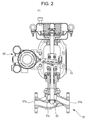
Fig. 2 is an overall external view illustrating the overall configuration of a valve according to the first embodiment; -
Fig. 3 is a block diagram illustrating the configuration of a monitoring apparatus according to the first embodiment; -
Fig. 4 is a graph illustrating changes in the opening of the valve according to the first embodiment; -
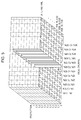
Fig. 5 is a histogram illustrating the distribution of the openings of the valve according to the first embodiment; -
Fig. 6 is a diagram illustrating an example of presentation of failure factor candidates according to the first embodiment; -
Fig. 7 is a block diagram illustrating the configuration of a failure factor identification supporting system according to a second embodiment; -
Fig. 8 is a block diagram illustrating the configuration of a monitoring apparatus according to the second embodiment; -
Fig. 9 is a diagram an example of presentation of failure factor candidates according to the second embodiment; and -
Fig. 10 is a block diagram illustrating the configuration of a failure factor identification supporting system according to a third embodiment. - Hereinafter, embodiments of the present invention will be described with reference to the drawings.
- Referring to
Fig. 1 , a failure factoridentification supporting system 100 according to a first embodiment of the present invention includes amonitoring apparatus 10, a failure factoridentification supporting apparatus 20, and adisplay device 31. The failure factoridentification supporting system 100 supports identification of a factor of a failure that occurs in a field device located in a fluid channel system. The term "fluid channel system" refers to a system that includes pipes through which fluid flows, and field devices such as valves V1 to V3 and sensors S1 to S3 located on the pipes. The fluid channel system is monitored by themonitoring apparatus 10 viacontrollers - Field devices in this case include, for example, the valves V1 to V3 and the sensors S1 to S3. The valves V1 to V3 have an identical configuration, and the sensors S1 to S3 have an identical configuration. The first embodiment will discuss the following case in which a failure occurs in the valve V1.
- Referring to
Fig. 2 , the valve V1 controls the flow rate of fluid that flows from anupstream channel 51 a to adownstream channel 51 b of avalve body 51, in accordance with the valve opening in accordance with the position in a vertical direction of avalve member 52 with respect to aseat 51 c. Apositioner 54 in the valve V1 detects the position in a vertical direction of thevalve member 52, which is detected via adetection lever 53, and outputs the detected position as valve opening information. - Referring to
Fig. 3 , themonitoring apparatus 10 includes adevice monitoring unit 10a, afailure detecting unit 10b, afailure recording unit 10c, afailure notification unit 10d, and anevent recording unit 10e. - The
device monitoring unit 10a monitors a command, from thecontroller 12, indicating the valve opening amount of each of the valves V1 to V3, and valve opening information, from thepositioner 54, indicating the actual valve opening amount of each of the valves V1 to V3. - The
failure detecting unit 10b detects a failure of the valve V1 on the basis of the command indicating the valve opening amount and the valve opening information, which are monitored by thedevice monitoring unit 10a. Specifically, thefailure detecting unit 10b detects that there is a failure in the value V1 when the actual valve opening amount of the valve V1 does not match the valve opening amount indicated in the command from thecontroller 12 and there is a great difference between the two amounts. A failure of the valve V1 refers to a state in which the valve V1 is incapable of operating normally, such as an operation error including a valve opening error, or a failure including a valve breakage. -
Fig. 4 is a graph representing deviation between a valve opening amount indicated in a command for the valve V1, from thecontroller 12, and the actual valve opening amount indicated by valve opening information when the valve V1 actually operates in response to that command. - Given a command from the
controller 12 indicating a valve opening amount of the valve V1, thefailure detecting unit 10b obtains a difference Δ between the valve opening amount indicated in the command and the actual valve opening amount of the valve V1. When the difference Δ exceeds a certain threshold th, thefailure detecting unit 10b determines that an unexpected valve opening error is occurring in the valve V1. -
Fig. 5 is a histogram indicating the distribution of the valve openings of the valve V1 in chronological order (date and time). This histogram indicates the hourly frequency distribution of valve openings actually measured within a defined time (such as 24 hours) in response to a command indicating a valve opening amount of the valve V1. That is, when the valve V1 is ideally normally operating, the valve opening amounts will be concentrated only within the range of valve opening amounts that match the valve opening amount indicated in the command (50% to 60% in this case). - The unexpected (sudden) occurrence of a valve opening error of the valve V1 means sudden transition from a state where the valve opening amounts are concentrated only around the valve opening amount (50% to 60%) indicated in the command from the
controller 12 to a state where the valve opening amounts greatly deviating from the command are actually measured. - On February 18 at 7:00, about 90% of the valve opening amounts are distributed in the area of the valve opening amounts (50% to 60%). At the same time, about 10% are distributed in the area of the valve opening amounts (40% to 50%), which means that the valve opening amounts of the valve V1 deviating from the command from the
controller 12 are actually measured. Therefore, thefailure detecting unit 10b determines that "February 18, 7:00" is the time point at which the unexpected failure "valve opening error" occurs in the valve V1. - The
failure detecting unit 10b generates failure information including information that indicates the specific details of the failure "valve opening error" (hereinafter referred to as "failure details information"), and information that indicates the failure occurrence date and time of the time point "February 18, 7:00" at which the failure occurs (hereinafter referred to as "failure time point information"). - The
failure recording unit 10c records the failure information (failure details information and failure time point information) on the valve V1, generated by thefailure detecting unit 10b, in adatabase 11. In this case, thefailure recording unit 10c records in thedatabase 11 the failure information in the state of a table where the date and time (February 18, 7:00), indicated by the failure time point information, and the failure details information are associated with each other. - Upon detection by the
failure detecting unit 10b of the occurrence of an unexpected failure in the valve V1, thefailure notification unit 10d notifies the failure factoridentification supporting apparatus 20 of a failure detection signal indicating the occurrence of the failure. - When an event of some kind is performed by an operator in the fluid channel system in the field, the
event recording unit 10e records in thedatabase 11 information representing the details of that event (hereinafter referred to as "event information"). The term "event" refers to an incident of maintenance performed by the operator on a field device other than the valve V1 that is a device in question where a failure is occurring, an operation of some kind performed by the operator, such as exchanging or repairing a part, or activation of a field device other than the valve V1 by thecontroller - The event information includes information that indicates the specific details of the event, such as maintenance or repair performed by the operator (hereinafter referred to as "event details information"), and information that indicates the event occurrence date and time of the time point at which the event occurs (hereinafter referred to as "event time point information").
- The
event recording unit 10e records in thedatabase 11 the event information, input by the operator who executes the event, in the state of a table where the event details information and the event time point information are associated with each other. Recording of the event information by theevent recording unit 10e is done separately and independently of recording of the failure information in thedatabase 11. - The functions of units of the
monitoring apparatus 10 described above are realized by installing a computer program (software) in a computer (hardware) including a central processing unit (CPU), memory, interface, and so forth. That is, the functions of thedevice monitoring unit 10a,failure detecting unit 10b,failure recording unit 10c,failure notification unit 10d, andevent recording unit 10e of themonitoring apparatus 10 are realized by cooperation between various hardware resources of the computer and the computer program. - The failure factor
identification supporting apparatus 20 includes a failureinformation obtaining unit 21, an eventinformation obtaining unit 22, and a failure factorcandidate output unit 23. The failure factorcandidate output unit 23 includes a timepoint checking unit 24 and anoutput unit 30. - The failure
information obtaining unit 21 obtains failure information on the valve V1 from themonitoring apparatus 10. Specifically, upon notification by thefailure notification unit 10d in themonitoring apparatus 10 of a failure detection signal indicating a failure of the valve V1, the failureinformation obtaining unit 21 requests themonitoring apparatus 10 to send failure information corresponding to the failure detection signal. - On receipt of failure information read from the
database 11 via thefailure recording unit 10c in themonitoring apparatus 10, the failureinformation obtaining unit 21 outputs the failure information to the timepoint checking unit 24 and outputs failure time point information included in the failure information to the eventinformation obtaining unit 22. - The event
information obtaining unit 22 obtains event information from themonitoring apparatus 10. Specifically, the eventinformation obtaining unit 22 requests themonitoring apparatus 10 to send event information within a time range that goes back 48 hours from a failure occurrence date and time indicated by the failure time point information received from the failureinformation obtaining unit 21. - The time range going back 48 hours from the failure occurrence date and time is a time range twice a defined time (24 hours) in aggregating the valve opening distribution (
Fig. 5 ). However, this time range is not limited to 48 hours and may alternatively be set to an arbitrary range. - Upon receipt of a plurality of items of event information read from the
database 11 via theevent recording unit 10e in themonitoring apparatus 10, the eventinformation obtaining unit 22 outputs the plurality of items of event information to the timepoint checking unit 24. - The time
point checking unit 24 checks the failure time point information (failure occurrence date and time) included in the failure information received from the failureinformation obtaining unit 21 against two items of event time point information (event occurrence date and time) included in two items of event information received from the eventinformation obtaining unit 22, and compares the failure occurrence date and time with each event occurrence date and time. Specifically, the timepoint checking unit 24 compares the failure occurrence date and time with each event occurrence date and time, and uses the closeness between the two in terms of time as a determination material for determining a failure factor candidate. - Even when there are ten items of event information within the time range going back 48 hours, if there are two items of event information within a time range where the closeness in terms of time between the failure occurrence date and time and each event occurrence date and time is within, for example, 20 hours, that is, a time range going back, for example, 20 hours from the failure occurrence date and time, the time
point checking unit 24 regards these two items of event information as candidates. If there are ten items of event information within the time range going back 48 hours, the timepoint checking unit 24 may regard all of these items of event information as candidates. - The time
point checking unit 24 determines, out of the two items of event information within the time range going back 20 hours from the failure occurrence date and time, first event information whose event occurrence date and time is closest in terms of time to the failure occurrence date and time as a first failure factor candidate, and determines second event information next closest to the failure occurrence date and time as a second failure factor candidate. Thereafter, the timepoint checking unit 24 generates image data representing a list of failure factor candidates on the basis of the failure information and the first and second items of event information, and supplies the image data to theoutput unit 30. - The
output unit 30 outputs the image data representing a list of failure factor candidates, supplied from the timepoint checking unit 24, to thedisplay device 31 which is an external device. - The functions of units of the failure factor
identification supporting apparatus 20 are realized by installing a computer program (software) in a computer (hardware) including a CPU, memory, interface, and so forth. The functions of the units of the failure factoridentification supporting apparatus 20 are realized by cooperation between various hardware resources of the computer and the computer program. - The
display device 31 is a monitor such as a liquid crystal display (LCD), or a display device of a personal computer. Thedisplay device 31 receives the image data representing a list of failure factor candidates, output from theoutput unit 30, and displays and provides a failure factor candidate list screen corresponding to that image data representing the list. - Being notified by the
failure notification unit 10d in themonitoring apparatus 10 of a failure detection signal indicating a failure of the valve V1, the failureinformation obtaining unit 21 in the failure factoridentification supporting apparatus 20 obtains failure information from themonitoring apparatus 10, outputs failure time point information included in the failure information to the eventinformation obtaining unit 22, and outputs the failure information to the timepoint checking unit 24 in the failure factorcandidate output unit 23. - Upon receipt of the failure time point information from the failure
information obtaining unit 21, the eventinformation obtaining unit 22 obtains ten items of event information stored within a time range that goes back 48 hours from February 18, 2015, 7:00, which is the occurrence date and time of the failure in the value V1, indicated by the failure time point information, from theevent recording unit 10e in themonitoring apparatus 10. The eventinformation obtaining unit 22 extracts, from among the ten items of event information, two items of event information within the range of past 20 hours as candidates. - For example, the event
information obtaining unit 22 determines, as candidates, first event information indicating a first event that takes place about 10 hours before the occurrence date and time of the failure in the valve V1, and second event information indicating a second event that takes place about 16 hours before the occurrence date and time of the failure in the valve V1. - The first event information is about the first event, which is maintenance that replaces part of a piping component A located upstream of a pipe where the valve V1 is located, on February 17, 2015, at 21:00, which is about 10 hours before the failure occurrence date and time.
- The second event information is about the second event, which is an inspection of a fixed-valve-opening manual valve B located further upstream of the above-mentioned piping component A, on February 17, 2015, at 15:00, which is about 16 hours before the failure occurrence date and time.
- The time
point checking unit 24 compares failure time point information (failure occurrence date and time) included in the failure information on the valve V1 received from the failureinformation obtaining unit 21 with first event time point information (the event occurrence date and time, which is about 10 hours before the failure occurrence date and time) included in the first event information received from the eventinformation obtaining unit 22. Furthermore, the timepoint checking unit 24 compares the failure time point information (failure occurrence date and time) with second event time point information (the event occurrence date and time, which is about 16 hours before the failure occurrence date and time) included in the second event information. - As a result, the time
point checking unit 24 determines the order of priority of the failure factor candidates on the basis of the closeness in terms of time. That is, the timepoint checking unit 24 determines the first event, which is closer in terms of time to the occurrence date and time of the failure in the valve V1, as a first failure factor candidate, and the second event, which is next closer in terms of time to the failure occurrence date and time, as a second failure factor candidate. - The time
point checking unit 24 generates image data representing a list of failure factor candidates in which the first event information and the second event information, to which information representing the order of priority is added, are arranged in the order of the first failure factor candidate and the second failure factor candidate, and supplies the image data to theoutput unit 30. - The
output unit 30 outputs the image data representing a list of failure factor candidates to thedisplay device 31, and thedisplay device 31 displays a failure factor candidate list screen G1 (hereinafter referred to as a "candidate list screen") corresponding to the image data representing the list, as illustrated inFig. 6 . - The candidate list screen G1 presents that a field device in question where a "failure" occurs is a "valve", the details of the failure indicate an "opening distribution error", and the failure occurrence date and time is "February 18, 2015, 7:00".
- The candidate list screen G1 also presents that the details of the "first event" determined as the first failure factor candidate indicate "(1) piping component A replacement", and the event occurrence date and time is "February 17, 2015, 21:00". Likewise, the candidate list screen G1 presents that the details of the "second event" determined as the second failure factor candidate indicate "(2) manual valve B inspection", and the event occurrence date and time is "February 17, 2015, 15:00".
- Therefore, an operator who checks the candidate list screen G1 can recognize that the first failure factor candidate, which is more likely to be the failure factor of the valve V1, is the first event "(1) piping component A replacement", and the second failure factor candidate is the second event "(2) manual valve B inspection".
- In order to check whether the first event "(1) piping component A replacement", which is the first failure factor candidate, is the failure factor of the valve V1, the operator can actually investigate the piping component A. As a result, for example, it may turn out that, because the accuracy of reattaching the piping component A has been low and accordingly turbulence and drift have been caused in the flow of fluid near the valve V1, the occurrence of the turbulence and drift is the failure factor of the opening distribution error of the valve V1. In such a case, the efficiency in identifying the failure factor of the valve V1 is particularly improved.
- However, as a result of the actual investigation of the piping component A, even when it turns out that the first event "piping component A replacement" is not the failure factor of the valve V1, since the failure factor
identification supporting apparatus 20 does not automatically detect the failure factor but simply provides candidates of the failure factor, the fact remains that the failure factoridentification supporting apparatus 20 supports identification of the failure factor. - Even if the physical causal relationship between the valve V1 where a failure occurs and a peripheral device such as the piping component A or the manual valve B located nearby is unclear, when the occurrence date and time of the failure in the valve V1 is checked against the event occurrence date and time of the piping component A and the event occurrence date and time of the manual valve B, the failure factor
identification supporting apparatus 20 can provide failure factor candidates based on the order of priority with reference to the closeness in terms of time between the occurrence dates and times. - Since the failure factor
identification supporting apparatus 20 extracts and provides failure factor candidates only in accordance with the closeness in terms of time between the failure occurrence date and time and the event occurrence date and time, even if the failure factor of the valve V1 is unconceivable by the operator because it has no direct causal relationship with the valve V1, the failure factoridentification supporting apparatus 20 can efficiently support identification of the failure factor. - Referring to
Fig. 7 , a failure factoridentification supporting system 200 according to a second embodiment includes amonitoring apparatus 210, a failure factoridentification supporting apparatus 220, and thedisplay device 31. In the second embodiment, the failureinformation obtaining unit 21, eventinformation obtaining unit 22,output unit 30, anddisplay device 31 which are the same elements as those in the failure factoridentification supporting system 100 illustrated inFig. 1 are denoted by the same reference numerals, and detailed descriptions thereof are omitted. - Referring to
Fig. 8 , themonitoring apparatus 210 includes, in addition to thedevice monitoring unit 10a,failure detecting unit 10b, andfailure notification unit 10d of themonitoring apparatus 10 of the first embodiment, a failure deviceposition recording unit 210a, afailure recording unit 210c, and anevent recording unit 210e. The same elements as those of themonitoring apparatus 10 are denoted by the same reference numerals, and detailed descriptions thereof are omitted. - The failure device
position recording unit 210a pre-records position information on the valve V1 where an unexpected failure occurs (hereinafter referred to as "failure device position information") in association with the above-described failure information on the valve V1 (failure details information and failure time point information) in thedatabase 11. Failure device position information is instrumentation position information representing a piping position at which the valve V1 is located. - For example, when the position of a tank located the most upstream of the piping of a fluid channel system where a fluid α flows serves as the upstream origin and when the valve V1 is located at a position that is 45 m ahead of the upstream origin toward the downstream side of the piping, the failure device position information on the valve V1 is information that indicates the distance "45 m".
- The
event recording unit 210e records, in addition to the above-described event information (event details information and event time point information), information that indicates the occurrence position of the event (a piping position at which another field device where the event occurs is located) (hereinafter referred to as "event occurrence position information") in thedatabase 11. The event occurrence position information is also input by the operator who performs the event. - For example, when the position of a tank located the most upstream of the piping of the fluid channel system of the fluid α serves as the upstream origin and when the piping component A is located at a position that is 43 m ahead of the upstream origin toward the downstream side of the piping, the event occurrence position information is information that indicates the distance "43 m".
- The failure factor
identification supporting apparatus 220 includes the failureinformation obtaining unit 21, the eventinformation obtaining unit 22, a failure device positioninformation obtaining unit 26, an event occurrence positioninformation obtaining unit 27, and a failure factorcandidate output unit 28. The failure factorcandidate output unit 28 includes a time pointposition checking unit 29 and theoutput unit 30. The same elements as those of the failure factoridentification supporting apparatus 20 are denoted by the same reference numerals, and detailed descriptions thereof are omitted. - Like the first embodiment, the failure
information obtaining unit 21 and the eventinformation obtaining unit 22 output failure information on the valve V1 and a plurality of items of event information, obtained from themonitoring apparatus 10, to the time pointposition checking unit 29 in the failure factorcandidate output unit 28. - The failure device position
information obtaining unit 26 obtains failure device position information on the valve V1 where an unexpected failure occurs, from themonitoring apparatus 10. The event occurrence positioninformation obtaining unit 27 obtains event occurrence position information corresponding to event information obtained by the eventinformation obtaining unit 22, from themonitoring apparatus 10. - The time point
position checking unit 29 includes a first quantization unit 29aa, a second quantization unit 29ab, an evaluationvalue calculating unit 29b, and a priorityorder determining unit 29c. - The first quantization unit 29aa quantizes the closeness in terms of time between the occurrence date and time of the failure in the valve V1 and each event occurrence date and time on the basis of a predetermined normalization index. The second quantization unit 29ab quantizes the closeness in terms of position between the failure device position of the valve V1 and each event occurrence position on the basis of a predetermined normalization index.
- The evaluation
value calculating unit 29b weights a quantized value obtained by the first quantization unit 29aa as a result of quantizing the closeness in terms of time and a quantized value obtained by the second quantization unit 29ab as a result of quantizing the closeness in terms of position using a certain weight coefficient, and adds the weighted quantized values, thereby calculating an evaluation value of each event. - The priority
order determining unit 29c determines the order of priority of items of event information serving as candidates of a failure factor on the basis of the evaluation value of each event, calculated by the evaluationvalue calculating unit 29b. The priorityorder determining unit 29c generates image data representing a list of failure factor candidates, in which the order of priority is indicated, and outputs the generated image data to theoutput unit 30. Theoutput unit 30 outputs the image data representing the list to thedisplay device 31. - Being notified by the
monitoring apparatus 10 of a failure detection signal, the failureinformation obtaining unit 21 in the failure factoridentification supporting apparatus 220 obtains failure information from themonitoring apparatus 10, outputs failure time point information included in the failure information to the eventinformation obtaining unit 22, and outputs the failure information to the time pointposition checking unit 29 in the failure factorcandidate output unit 28. - Upon receipt of the failure time point information from the failure
information obtaining unit 21, the eventinformation obtaining unit 22 obtains, for example, two items of event information stored within a time range that goes back 48 hours from February 18, 2015, 7:00, which is indicated by the failure time point information, from themonitoring apparatus 10. - For example, the event
information obtaining unit 22 obtains first event information corresponding to a first event (piping component A replacement) that takes place about 16 hours before the occurrence date and time of the failure in the valve V1, and second event information corresponding to a second event (manual valve B inspection) that takes place about 10 hours before the occurrence date and time of the failure in the valve V1. - In the first embodiment, the first event takes place about 10 hours before the failure occurrence date and time, and the second event takes place about 16 hours before the failure occurrence date and time. However, the second embodiment will discuss an exemplary case where, as has been described above, the first event takes place about 16 hours before the failure occurrence date and time, and the second event takes place about 10 hours before the failure occurrence date and time. Note that the event details of the first event information and the second event information are the same as those in the first embodiment.
- In response to notification of a failure detection signal indicating a failure of the valve V1, the failure device position
information obtaining unit 26 requests themonitoring apparatus 10 to send failure device position information, obtains failure device position information on the valve V1 via thefailure recording unit 210c in themonitoring apparatus 10, and outputs the failure device position information to the time pointposition checking unit 29. - The event occurrence position
information obtaining unit 27 requests themonitoring apparatus 10 to send event occurrence position information corresponding to the first event information and the second event information, obtained by the eventinformation obtaining unit 22. When the event occurrence positioninformation obtaining unit 27 obtains first event occurrence position information and second event occurrence position information corresponding to the first event information and the second event information, respectively, via the event recording unit 210b in themonitoring apparatus 10, the event occurrence positioninformation obtaining unit 27 outputs these items of event occurrence position information to the time pointposition checking unit 29. - Specifically, the position of a tank located the most upstream of the piping of the fluid channel system of the fluid α serves as the upstream origin, and the event occurrence position
information obtaining unit 27 obtains the first event occurrence position information (distance "43 m") indicating that the piping component A is located at a position that is 43 m ahead of the upstream origin toward the downstream side of the piping. - Also, the position of a tank located the most upstream of the piping of the fluid channel system of the fluid α serves as the upstream origin, and the event occurrence position
information obtaining unit 27 obtains the second event occurrence position information (distance "20 m") indicating that the manual valve B is located at a position that is 20 m ahead of the upstream origin toward the downstream side of the piping. - In this case, the piping component A is located at a position that is upstream by 2 m (45 m - 43 m) of the position where the valve V1 is located, and the manual valve B is located at a position that is upstream by 25 m (45 m - 20 m) of the position of the valve V1.
- The first quantization unit 29aa in the time point
position checking unit 29 quantizes a time point interval Pt1 indicating a temporal interval between the occurrence date and time of the failure in the valve V1 and the first event occurrence date and time of the first event (piping component A replacement) using a predetermined normalization index (48 hours in this case) as described below by equation (1):
- The first quantization unit 29aa also quantizes a time point interval Pt2 indicating a temporal interval between the occurrence date and time of the failure in the valve V1 and the second event occurrence date and time of the second event (manual valve B inspection) using the predetermined normalization index (48 hours in this case) as described below by equation (2):

Fig. 5 ). - According to equations (1) and (2), the value of the time point interval Pt2 is greater than the value of the time point interval Pt1. Thus, it is clear that the second event occurrence date and time of the second event (manual valve B inspection) is temporally closer to the occurrence date and time of the failure in the valve V1 than the first event occurrence date and time of the first event (piping component A replacement) is.
- Next, the second quantization unit 29ab in the time point
position checking unit 29 quantizes a position interval Pd1 indicating a position interval between the failure device position (45 m) of the valve V1 and the first event occurrence position (43 m) of the first event (piping component A replacement) using a predetermined normalization index (30 m in this case) as described below by equation (3):
- The second quantization unit 29ab also quantizes a position interval Pd2 indicating a position interval between the failure device position of the valve V1 and the second event occurrence position (20 m) of the second event (manual valve B inspection) using the predetermined normalization index (30 m in this case) as described below by equation (4):

- Although the normalization index is set to a distance of 30 m in this case, the normalization index may be set to an arbitrary distance as long as the value of a numerator in each of equations (3) and (4) does not become negative. When the distance between the failure device position of the valve V1 and each event occurrence position is greater than 30 m, that is, when the value of a numerator in each of equations (3) and (4) becomes negative, the values of the position intervals Pd1 and Pd2 are set to "0.0", which is the lower limit value.
- According to equations (3) and (4), the value of the position interval Pd1 is greater than the value of the position interval Pd2. Thus, it is clear that the first event occurrence position of the first event (piping component A replacement) is positionally closer to the failure device position of the valve V1 than the second event occurrence position of the second event (manual valve B inspection) is.
- The evaluation
value calculating unit 29b in the time pointposition checking unit 29 weights quantized values obtained as a result of quantizing the closeness in terms of time using equations (1) and (2) and quantized values obtained as a result of quantizing the closeness in terms of position using equations (3) and (4) by using certain weight coefficients p and q, respectively, and adds the weighted quantized values, as described below in equations (5) and (6). Accordingly, the evaluationvalue calculating unit 29b can calculate an evaluation value P1 of the first event and an evaluation value P2 of the second event:

- When the weight coefficients p and q are 1, for example (p = 1 and q = 1), the evaluation value P1 of the first event and the evaluation value P2 of the second event will be as described below by equations (7) and (8):


- Accordingly, it is clear that the evaluation value P1 of the first event is greater than the evaluation value P2 of the second event. Although the weight coefficients p and q are simply 1 (p = 1 and q - 1) in the above case, if the closeness in terms of time is given greater importance, the weight coefficient p is set to a value greater than q; and, if the closeness in terms of position is given greater importance, the weight coefficient q is set to a value greater than p. These weight coefficients p and q may be set to arbitrary values.
- If only the closeness in terms of time is taken into consideration, because the value of the time point interval Pt2 is greater than the value of the time point interval Pt1, the priority
order determining unit 29c in the time pointposition checking unit 29 assigns a higher priority to the second event (manual valve B inspection) with respect to the occurrence date and time of the failure in the valve V1. However, when the evaluation values P1 and P2 which take into consideration the closeness in terms of position in addition to the closeness in terms of time are compared with each other, the priorityorder determining unit 29c may assign a higher priority to the first event (piping component A replacement) for which the evaluation value P1 is calculated. - As described above, the time point
position checking unit 29 can calculate the evaluation values P1 and P2 by quantizing both the closeness in terms of time between the failure occurrence date and time and each event occurrence date and time and the closeness in terms of position between the failure device position and each event occurrence position and adding the quantized values, and determine the order of priority of failure factor candidates in descending order of the evaluation values P1 and P2. - The closeness in terms of position between the failure device position of the valve V1 and each event occurrence position corresponds to each of the distances Pd1 and Pd2 between the failure device position and each event occurrence position in the piping, which are continuous in terms of an identical fluid channel system. Thus, the time point
position checking unit 29 can provide event information on an event that is highly relevant to the failure factor of the valve V1 as a failure factor candidate. - The priority
order determining unit 29c in the time pointposition checking unit 29 generates image data representing a list of failure factor candidates in which the first event information and the second event information are arranged in the determined order of priority, and supplies the image data to theoutput unit 30. - The
output unit 30 outputs the image data representing a list of failure factor candidates to thedisplay device 31, and thedisplay device 31 displays a failure factor candidate list screen G2 (hereinafter referred to as a "candidate list screen") corresponding to the image data representing the list, as illustrated inFig. 9 . - The candidate list screen G2 presents that a device in question where a "failure" occurs is a "valve", the details of the failure indicate an "opening distribution error", and the failure occurrence date and time is "February 18, 2015, 7:00".
- The candidate list screen G2 also presents that the details of the "first event" determined as the first failure factor candidate indicate "(1) piping component A replacement", and the event occurrence date and time is "February 17, 2015, 15:00". Likewise, the candidate list screen G2 presents that the details of the "second event" determined as the second failure factor candidate indicate "(2) manual valve B inspection", and the event occurrence date and time is "February 17, 2015, 21:00".
- Furthermore, the candidate list screen G2 displays the evaluation values P1 and P2 ("1.600" and "0.959") indicating the basis for determining the order of priority of the first failure factor candidate and the second failure factor candidate.
- Therefore, an operator who checks the candidate list screen G2 can recognize that the first failure factor candidate, which is more likely to be the failure factor of the valve V1 where a failure occurs, is the first event "(1) piping component A replacement", and the second failure factor candidate is the second event "(2) manual valve B inspection".
- As has been described above, since the failure factor
identification supporting apparatus 220 determines the order of priority of failure factor candidates while taking into consideration the closeness in terms of position between the valve V1 and each event, in addition to the closeness in terms of time between the valve V1 and each event, the accuracy of identifying that an event serving as a failure factor candidate is the actual failure factor can be further improved, and efficient identification of the failure factor can be supported. -
Fig. 10 is a block diagram illustrating the overall configuration of atemperature control system 300 according to a third embodiment, to which the failure factoridentification supporting system 200 according to the second embodiment is applied. The following case will be described by way of example in which aheater 301, which is one element of a field device included in thetemperature control system 300, is a target where a failure is occurring in the failure factoridentification supporting system 200. - The
temperature control system 300 includes a box-shapedchamber 310;heaters 301 to 304 that are arranged in a horizontal direction in internal space of thechamber 310, having a slight gap therebetween and not overlapping one another; a plate-shaped to-be-heated member 305 located, in the internal space of thechamber 310, facing theheaters 301 to 304 while being vertically separated from theheaters 301 to 304; a plate-shaped table 306 for placing the to-be-heated member 305;temperature sensors 331 to 334 fixed to a bottom face of the table 306 so as to face theheaters 301 to 304;power regulators 311 to 314 located outside thechamber 310 and electrically connected to theheaters 301 to 304; andtemperature controllers 321 to 324 that are connected to output terminals of thetemperature sensors 331 to 334 and that control thepower regulators 311 to 314. - In this case, the
temperature controller 321,power regulator 311,heater 301, to-be-heated member 305, table 306, andtemperature sensor 331 configure atemperature control system 300a for controlling temperature. Likewise,temperature control systems 300b to 300d are configured. That is, thetemperature control system 300 includes fourtemperature control systems 300a to 300d that have continuity in terms of system. However, there is no continuity in terms of system or no direct relevance between thetemperature control systems 300a to 300d. - When an unexpected failure occurs in the
heater 301, the failure device positioninformation obtaining unit 26 obtains failure device position information on theheater 301 from themonitoring apparatus 10, and outputs the failure device position information to the time pointposition checking unit 29. - The event occurrence position
information obtaining unit 27 obtains not only the event occurrence position of an event performed on another field device (such as thepower regulator 311,temperature controller 321, or temperature sensor 331) in thetemperature control system 300a including theheater 301, but also the event occurrence position of each of theheaters 302 to 304 in the othertemperature control systems 300b to 300d that are within a distance range spatially close to theheater 301. The reason for the above is that, although there is no continuity in terms of system or no direct relevance, it is likely that theheater 301 is influenced by heat transfer of theheaters 302 to 304 which are spatially close to theheater 301. - For example, when an event that is namely maintenance is performed on each of the
heaters temperature control systems heater 301, the event occurrence positioninformation obtaining unit 27 requests themonitoring apparatus 10 to send event occurrence position information on theheaters position checking unit 29. - The failure device position of the
heater 301 is the position where theheater 301 is located in thetemperature control system 300a. The event occurrence positions of the events on theheaters heater 301 is located in thetemperature control system 300a, which serves as a reference position, to theheaters temperature control systems - Therefore, event occurrence position information is such that, when the position where the
heater 301 is located in thechamber 310 is defined as a reference position (0 m), among the arrangedheaters 301 to 304, the horizontal position where theheater 302 is located is, for example, 0.5 m from the reference position, and the horizontal position where theheater 303 is located is, for example, 2 m from the reference position. Therefore, it is clear in this case that theheater 302 is located at a position that is spatially closest to theheater 301. - In addition to the closeness in terms of time between the failure occurrence time point of the
heater 301 and each of the event occurrence time points of theheaters position checking unit 29 takes into consideration the closeness in terms of spatial position between the failure device position of theheater 301 and each of the event occurrence positions of theheaters heaters - Therefore, even when there is no continuity in terms of system among the
temperature control systems heater 302 which is highly related to the failure factor of theheater 301 can be provided as a key failure factor candidate. - Although the above-described first embodiment has discussed the case where the time
point checking unit 24 in the failure factorcandidate output unit 23 provides failure factor candidates on the candidate list screen G1 in which event information whose event occurrence date and time closer in terms of time to the failure occurrence date and time is assigned a higher priority, the present invention is not limited to this case. A plurality of failure factor candidates simply listed on a candidate list screen may be provided, without assigning priorities to a plurality of items of event information received from the eventinformation obtaining unit 22. - Although the above-described first embodiment has discussed the case where the closeness in terms of time is determined every hour, the present invention is not limited to this case. The closeness in terms of time may be determined at various other time intervals, such as every day or every week.
- Furthermore, although the above-described second embodiment has discussed the case where the failure device position of the valve V1 or each event occurrence position is determined by a distance from the upstream origin in the fluid channel system, the present invention is not limited to this case. The failure device position or each event occurrence position may be determined by a distance from the downstream origin.
- Furthermore, although the above-described first and second embodiments have discussed the cases where, when a failure occurs in the valve V1, an event performed on another device other than the valve V1 serves as a failure factor candidate, the present invention is not limited to these cases. An event such as maintenance performed on the valve V1 itself may serve as a failure factor candidate. In this case, the failure device position of the valve V1 and the event occurrence position of the valve V1 are the same, and hence the distance between the two positions is simply Pd1 = 1.0.
- Furthermore, although the above-described first to third embodiments have discussed the cases where the fluid channel system and the temperature control system serve as systems to which the present invention is applicable, the present invention is not limited to these cases. The present invention is applicable to various systems such as a pressure control system, and candidates of a factor of a failure in a field device in such systems may be provided.
-
- 10, 210...monitoring apparatus, 10a...device monitoring unit, 10b...failure detecting unit, 10c...failure recording unit ,10d...failure notification unit, 10e...event recording unit, 11...database, 20, 220...failure factor identification supporting apparatus, 21...failure information obtaining unit, 22...event information obtaining unit, 23, 28...failure factor candidate output unit, 24...time point checking unit (candidate order determining unit), 30...output unit, 26...failure device position information obtaining unit, 27...event occurrence position information obtaining unit, 29...time point position checking unit (candidate order determining unit), 29aa...first quantization unit, 29ab...second quantization unit, 29b...evaluation value calculating unit, 29c...priority order determining unit, 31...display device, V1-V3...valve, S1-S3...sensor, 51...valve body, 52...valve member, 53...detection lever, 54...positioner, 100, 200...failure factor identification supporting system, 300...temperature control system.
Claims (8)
- A failure factor identification supporting apparatus comprising:a failure time point information obtaining unit that obtains information regarding a failure occurrence time point at which a failure occurs in a field device located in a field;an event information obtaining unit that obtains event information regarding, among one or more events that occur in the field, an event that occurs within a certain time range prior to the failure occurrence time point, and an event occurrence time point at which the event occurs; anda failure factor candidate output unit that outputs the event information, obtained by the event information obtaining unit, as a failure factor candidate.
- The failure factor identification supporting apparatus according to Claim 1, wherein:the failure factor candidate output unit includes:a candidate order determining unit that, when the event information obtaining unit obtains a plurality of items of event information, determines order of priority of failure factor candidates corresponding to the plurality of items of event information, based on closeness in terms of time between the failure occurrence time point and each event occurrence time point; andan output unit that outputs the failure factor candidates to which information representing the order of priority is added.
- The failure factor identification supporting apparatus according to Claim 2, further comprising:a failure device position information obtaining unit that obtains failure device position information indicating a position of the field device in which the failure occurs; andan event occurrence position information obtaining unit that obtains event occurrence position information indicating a position where each event occurs,wherein the candidate order determining unit determines the order of priority of the failure factor candidates in accordance with closeness in terms of time between the failure occurrence time point and each event occurrence time point, and closeness in terms of position between the position of the field device in which the failure occurs and each event occurrence position.
- The failure factor identification supporting apparatus according to Claim 3, wherein:the candidate order determining unitcalculates an evaluation value of each event by weighting the closeness in terms of time and the closeness in terms of position, anddetermines the order of priority of the failure factor candidates, based on the evaluation value.
- The failure factor identification supporting apparatus according to Claim 4, wherein:the candidate order determining unit includes:a first quantization unit that quantizes the closeness in terms of time based on a predetermined normalization index;a second quantization unit that quantizes the closeness in terms of position based on a predetermined normalization index; andan evaluation value calculating unit that calculates an evaluation value of each event by adding a quantized value of the closeness in terms of time and a quantized value of the closeness in terms of position.
- The failure factor identification supporting apparatus according to any one of Claims 3 to 5, wherein:the field device is located at any position in a fluid channel system in which fluid flows,each event occurs at an arbitrary position different from the position of the field device in the fluid channel system,the failure device position is determined by a distance from an arbitrary origin in the fluid channel system, andthe event occurrence position is determined by a distance from the arbitrary origin.
- The failure factor identification supporting apparatus according to any one of Claims 2 to 4, wherein:the field device is located at any position in a first temperature control system for controlling temperature,each event occurs at any position in a second temperature control system that is near the first temperature control system,the failure device position is determined by a distance from an arbitrary reference position in the first temperature control system, andthe event occurrence position is determined by a spatial distance from the reference position in the first temperature control system to the second temperature control system.
- A failure factor identification supporting method comprising:a failure time point information obtaining step of obtaining, with a failure time point information obtaining unit, information regarding a failure occurrence time point at which a failure occurs in a field device located in a field;an event information obtaining step of obtaining, with an event information obtaining unit, event information regarding, among on more events that occur in the field, an event that occurs within a certain time range prior to the failure occurrence time point, and an event occurrence time point at which the event occurs; anda candidate output step of outputting, with a failure factor candidate output unit, the event information, obtained in the event information obtaining step, as a failure factor candidate.
Applications Claiming Priority (1)
| Application Number | Priority Date | Filing Date | Title |
|---|---|---|---|
| JP2015055709A JP6339956B2 (en) | 2015-03-19 | 2015-03-19 | Defect factor identification support device and defect factor identification support method |
Publications (1)
| Publication Number | Publication Date |
|---|---|
| EP3070561A1 true EP3070561A1 (en) | 2016-09-21 |
Family
ID=55968874
Family Applications (1)
| Application Number | Title | Priority Date | Filing Date |
|---|---|---|---|
| EP16161048.0A Withdrawn EP3070561A1 (en) | 2015-03-19 | 2016-03-18 | Failure factor identification supporting apparatus and failure factor identification supporting method |
Country Status (4)
| Country | Link |
|---|---|
| US (1) | US9858138B2 (en) |
| EP (1) | EP3070561A1 (en) |
| JP (1) | JP6339956B2 (en) |
| CN (1) | CN105989414A (en) |
Families Citing this family (6)
| Publication number | Priority date | Publication date | Assignee | Title |
|---|---|---|---|---|
| JP2589563B2 (en) | 1988-12-21 | 1997-03-12 | 松下電器産業株式会社 | Traffic control device |
| JP3233995B2 (en) | 1992-07-10 | 2001-12-04 | マツダ株式会社 | Vehicle reporting system and device |
| DE102017116167A1 (en) * | 2017-07-18 | 2019-01-24 | Endress+Hauser Process Solutions Ag | Method for monitoring an automation system |
| JP6977522B2 (en) * | 2017-12-07 | 2021-12-08 | オムロン株式会社 | Control system, information processing device, anomaly factor estimation program |
| CN112600221B (en) * | 2020-12-08 | 2023-03-03 | 深圳供电局有限公司 | Reactive power compensation device configuration method, device, equipment and storage medium |
| JP2023173228A (en) * | 2022-05-25 | 2023-12-07 | 三菱重工業株式会社 | Abnormality determination device of facility, abnormality determination system, abnormality determination method, control method of abnormality determination system, and abnormality determination program |
Citations (6)
| Publication number | Priority date | Publication date | Assignee | Title |
|---|---|---|---|---|
| US20020183866A1 (en) * | 1999-04-02 | 2002-12-05 | Dean Jason Arthur | Method and system for diagnosing machine malfunctions |
| US20070282777A1 (en) * | 2006-05-30 | 2007-12-06 | Honeywell International Inc. | Automatic fault classification for model-based process monitoring |
| JP2013191002A (en) | 2012-03-14 | 2013-09-26 | Azbil Corp | Maintenance target valve selection device and selection method |
| EP2660675A1 (en) * | 2010-12-28 | 2013-11-06 | International Business Machines Corporation | Method, computer program, and computer for determining status of system |
| EP2749980A1 (en) * | 2012-12-27 | 2014-07-02 | Yokogawa Electric Corporation | Event analysis apparatus, non-transitory computer-readable storage medium storing computer program analyzing events, and method for analyzing events |
| US8838413B2 (en) * | 2011-05-12 | 2014-09-16 | Saudi Arabian Oil Company | Valve actuator fault analysis system |
Family Cites Families (10)
| Publication number | Priority date | Publication date | Assignee | Title |
|---|---|---|---|---|
| JPH06250733A (en) * | 1993-02-26 | 1994-09-09 | Toshiba Corp | Plant control equipment |
| US7746604B2 (en) * | 2002-04-02 | 2010-06-29 | General Electric Company | Method, system, and computer software code for detection and isolation of electrical ground failure and secondary failure |
| JP2003303014A (en) * | 2002-04-09 | 2003-10-24 | Toshiba Corp | Plant equipment maintenance management method and apparatus |
| JP2006031109A (en) * | 2004-07-12 | 2006-02-02 | Ntt Docomo Inc | Management system and management method |
| JP4074615B2 (en) * | 2004-11-17 | 2008-04-09 | 日立建機株式会社 | Diagnostic information display system for construction machinery |
| JP2006301910A (en) * | 2005-04-20 | 2006-11-02 | Yaskawa Information Systems Co Ltd | Fault operation history display method |
| US7065425B1 (en) * | 2005-06-22 | 2006-06-20 | Internaitonal Business Machines Corporation | Metrology tool error log analysis methodology and system |
| JP5179767B2 (en) * | 2007-03-12 | 2013-04-10 | 株式会社日立国際電気 | Substrate processing apparatus, display method thereof, data collection method, and event collection program |
| JP5625689B2 (en) * | 2010-09-29 | 2014-11-19 | 株式会社リコー | Management device, management system, and management method |
| JP2013191141A (en) * | 2012-03-15 | 2013-09-26 | Mitsubishi Electric Corp | Monitoring controller |
-
2015
- 2015-03-19 JP JP2015055709A patent/JP6339956B2/en active Active
-
2016
- 2016-03-10 CN CN201610135973.5A patent/CN105989414A/en active Pending
- 2016-03-16 US US15/072,099 patent/US9858138B2/en active Active
- 2016-03-18 EP EP16161048.0A patent/EP3070561A1/en not_active Withdrawn
Patent Citations (6)
| Publication number | Priority date | Publication date | Assignee | Title |
|---|---|---|---|---|
| US20020183866A1 (en) * | 1999-04-02 | 2002-12-05 | Dean Jason Arthur | Method and system for diagnosing machine malfunctions |
| US20070282777A1 (en) * | 2006-05-30 | 2007-12-06 | Honeywell International Inc. | Automatic fault classification for model-based process monitoring |
| EP2660675A1 (en) * | 2010-12-28 | 2013-11-06 | International Business Machines Corporation | Method, computer program, and computer for determining status of system |
| US8838413B2 (en) * | 2011-05-12 | 2014-09-16 | Saudi Arabian Oil Company | Valve actuator fault analysis system |
| JP2013191002A (en) | 2012-03-14 | 2013-09-26 | Azbil Corp | Maintenance target valve selection device and selection method |
| EP2749980A1 (en) * | 2012-12-27 | 2014-07-02 | Yokogawa Electric Corporation | Event analysis apparatus, non-transitory computer-readable storage medium storing computer program analyzing events, and method for analyzing events |
Also Published As
| Publication number | Publication date |
|---|---|
| CN105989414A (en) | 2016-10-05 |
| US9858138B2 (en) | 2018-01-02 |
| JP6339956B2 (en) | 2018-06-06 |
| JP2016177414A (en) | 2016-10-06 |
| US20160274964A1 (en) | 2016-09-22 |
Similar Documents
| Publication | Publication Date | Title |
|---|---|---|
| US9858138B2 (en) | Failure factor identification supporting apparatus and failure factor identification supporting method | |
| JP6687913B2 (en) | Leakage state estimation system, method, and recording medium | |
| US6735549B2 (en) | Predictive maintenance display system | |
| EP3346205B1 (en) | Inspection management system and inspection management method | |
| US9703754B2 (en) | Automatic remote monitoring and diagnosis system | |
| JP6605357B2 (en) | Anomaly detection apparatus, anomaly detection system and method | |
| CN108369109B (en) | Method for monitoring at least two redundant sensors | |
| US10641668B2 (en) | Measuring deformation of a compression spring to monitor performance of a safety valve | |
| JP6138066B2 (en) | Integrated maintenance management system | |
| EP3850452B1 (en) | Method and system for monitoring condition of a sample handling system of a gas analyser | |
| EA036230B1 (en) | Method and system of remote object monitoring | |
| EP2613263B1 (en) | Operations management device, operations management method, and program | |
| WO2018216197A1 (en) | Anomaly seriousness computation system, anomaly seriousness computation device, and anomaly seriousness computation program | |
| EP3647744A1 (en) | Gas meter management system | |
| US20140338420A1 (en) | Method of Determining a Calibration or Maintenance Time Interval | |
| KR20160052029A (en) | Method and system for providing tendency analisis service based buidding energy management index measurements system | |
| CN118913553A (en) | Self-adaptive pressure regulating system of air tightness detection equipment | |
| US20240248452A1 (en) | Method and monitoring device for monitoring the condition of a machine | |
| JP2016003875A (en) | Motor abnormality detecting system, motor abnormality detecting method, and motor abnormality detecting program | |
| JP2010276339A (en) | Sensor diagnostic method and sensor diagnostic device | |
| EP3955707A1 (en) | Method and system for predicting a failure probability of a component of an x-ray system | |
| JP2018106247A (en) | Data analysis apparatus and data analysis method | |
| KR101641259B1 (en) | Central control apparatus and central control sysytem and central control method | |
| CN116592944A (en) | LCP cabinet intelligent monitoring system | |
| WO2015087378A1 (en) | Water facility network abnormality detection device and abnormality detection method |
Legal Events
| Date | Code | Title | Description |
|---|---|---|---|
| PUAI | Public reference made under article 153(3) epc to a published international application that has entered the european phase |
Free format text: ORIGINAL CODE: 0009012 |
|
| AK | Designated contracting states |
Kind code of ref document: A1 Designated state(s): AL AT BE BG CH CY CZ DE DK EE ES FI FR GB GR HR HU IE IS IT LI LT LU LV MC MK MT NL NO PL PT RO RS SE SI SK SM TR |
|
| AX | Request for extension of the european patent |
Extension state: BA ME |
|
| 17P | Request for examination filed |
Effective date: 20161202 |
|
| RBV | Designated contracting states (corrected) |
Designated state(s): AL AT BE BG CH CY CZ DE DK EE ES FI FR GB GR HR HU IE IS IT LI LT LU LV MC MK MT NL NO PL PT RO RS SE SI SK SM TR |
|
| 17Q | First examination report despatched |
Effective date: 20180326 |
|
| GRAP | Despatch of communication of intention to grant a patent |
Free format text: ORIGINAL CODE: EPIDOSNIGR1 |
|
| INTG | Intention to grant announced |
Effective date: 20191114 |
|
| STAA | Information on the status of an ep patent application or granted ep patent |
Free format text: STATUS: THE APPLICATION IS DEEMED TO BE WITHDRAWN |
|
| 18D | Application deemed to be withdrawn |
Effective date: 20200603 |