EP3070524A1 - Imaging unit, vehicle control unit and heat transfer method for imaging unit - Google Patents
Imaging unit, vehicle control unit and heat transfer method for imaging unit Download PDFInfo
- Publication number
- EP3070524A1 EP3070524A1 EP16161088.6A EP16161088A EP3070524A1 EP 3070524 A1 EP3070524 A1 EP 3070524A1 EP 16161088 A EP16161088 A EP 16161088A EP 3070524 A1 EP3070524 A1 EP 3070524A1
- Authority
- EP
- European Patent Office
- Prior art keywords
- heat
- heat transfer
- imaging
- imaging unit
- stereo camera
- Prior art date
- Legal status (The legal status is an assumption and is not a legal conclusion. Google has not performed a legal analysis and makes no representation as to the accuracy of the status listed.)
- Granted
Links
Images


Classifications
-
- H—ELECTRICITY
- H04—ELECTRIC COMMUNICATION TECHNIQUE
- H04N—PICTORIAL COMMUNICATION, e.g. TELEVISION
- H04N23/00—Cameras or camera modules comprising electronic image sensors; Control thereof
- H04N23/50—Constructional details
- H04N23/51—Housings
-
- B—PERFORMING OPERATIONS; TRANSPORTING
- B60—VEHICLES IN GENERAL
- B60R—VEHICLES, VEHICLE FITTINGS, OR VEHICLE PARTS, NOT OTHERWISE PROVIDED FOR
- B60R11/00—Arrangements for holding or mounting articles, not otherwise provided for
- B60R11/04—Mounting of cameras operative during drive; Arrangement of controls thereof relative to the vehicle
-
- G—PHYSICS
- G03—PHOTOGRAPHY; CINEMATOGRAPHY; ANALOGOUS TECHNIQUES USING WAVES OTHER THAN OPTICAL WAVES; ELECTROGRAPHY; HOLOGRAPHY
- G03B—APPARATUS OR ARRANGEMENTS FOR TAKING PHOTOGRAPHS OR FOR PROJECTING OR VIEWING THEM; APPARATUS OR ARRANGEMENTS EMPLOYING ANALOGOUS TECHNIQUES USING WAVES OTHER THAN OPTICAL WAVES; ACCESSORIES THEREFOR
- G03B17/00—Details of cameras or camera bodies; Accessories therefor
- G03B17/02—Bodies
-
- G—PHYSICS
- G03—PHOTOGRAPHY; CINEMATOGRAPHY; ANALOGOUS TECHNIQUES USING WAVES OTHER THAN OPTICAL WAVES; ELECTROGRAPHY; HOLOGRAPHY
- G03B—APPARATUS OR ARRANGEMENTS FOR TAKING PHOTOGRAPHS OR FOR PROJECTING OR VIEWING THEM; APPARATUS OR ARRANGEMENTS EMPLOYING ANALOGOUS TECHNIQUES USING WAVES OTHER THAN OPTICAL WAVES; ACCESSORIES THEREFOR
- G03B17/00—Details of cameras or camera bodies; Accessories therefor
- G03B17/55—Details of cameras or camera bodies; Accessories therefor with provision for heating or cooling, e.g. in aircraft
-
- G—PHYSICS
- G03—PHOTOGRAPHY; CINEMATOGRAPHY; ANALOGOUS TECHNIQUES USING WAVES OTHER THAN OPTICAL WAVES; ELECTROGRAPHY; HOLOGRAPHY
- G03B—APPARATUS OR ARRANGEMENTS FOR TAKING PHOTOGRAPHS OR FOR PROJECTING OR VIEWING THEM; APPARATUS OR ARRANGEMENTS EMPLOYING ANALOGOUS TECHNIQUES USING WAVES OTHER THAN OPTICAL WAVES; ACCESSORIES THEREFOR
- G03B35/00—Stereoscopic photography
-
- G—PHYSICS
- G05—CONTROLLING; REGULATING
- G05D—SYSTEMS FOR CONTROLLING OR REGULATING NON-ELECTRIC VARIABLES
- G05D1/00—Control of position, course, altitude or attitude of land, water, air or space vehicles, e.g. using automatic pilots
- G05D1/02—Control of position or course in two dimensions
- G05D1/021—Control of position or course in two dimensions specially adapted to land vehicles
- G05D1/0231—Control of position or course in two dimensions specially adapted to land vehicles using optical position detecting means
-
- G—PHYSICS
- G06—COMPUTING OR CALCULATING; COUNTING
- G06V—IMAGE OR VIDEO RECOGNITION OR UNDERSTANDING
- G06V20/00—Scenes; Scene-specific elements
- G06V20/50—Context or environment of the image
- G06V20/56—Context or environment of the image exterior to a vehicle by using sensors mounted on the vehicle
- G06V20/58—Recognition of moving objects or obstacles, e.g. vehicles or pedestrians; Recognition of traffic objects, e.g. traffic signs, traffic lights or roads
-
- H—ELECTRICITY
- H04—ELECTRIC COMMUNICATION TECHNIQUE
- H04N—PICTORIAL COMMUNICATION, e.g. TELEVISION
- H04N13/00—Stereoscopic video systems; Multi-view video systems; Details thereof
- H04N13/20—Image signal generators
- H04N13/204—Image signal generators using stereoscopic image cameras
- H04N13/239—Image signal generators using stereoscopic image cameras using two two-dimensional [2D] image sensors having a relative position equal to or related to the interocular distance
-
- H—ELECTRICITY
- H05—ELECTRIC TECHNIQUES NOT OTHERWISE PROVIDED FOR
- H05K—PRINTED CIRCUITS; CASINGS OR CONSTRUCTIONAL DETAILS OF ELECTRIC APPARATUS; MANUFACTURE OF ASSEMBLAGES OF ELECTRICAL COMPONENTS
- H05K7/00—Constructional details common to different types of electric apparatus
- H05K7/20—Modifications to facilitate cooling, ventilating, or heating
- H05K7/2029—Modifications to facilitate cooling, ventilating, or heating using a liquid coolant with phase change in electronic enclosures
- H05K7/20336—Heat pipes, e.g. wicks or capillary pumps
-
- H—ELECTRICITY
- H05—ELECTRIC TECHNIQUES NOT OTHERWISE PROVIDED FOR
- H05K—PRINTED CIRCUITS; CASINGS OR CONSTRUCTIONAL DETAILS OF ELECTRIC APPARATUS; MANUFACTURE OF ASSEMBLAGES OF ELECTRICAL COMPONENTS
- H05K7/00—Constructional details common to different types of electric apparatus
- H05K7/20—Modifications to facilitate cooling, ventilating, or heating
- H05K7/20845—Modifications to facilitate cooling, ventilating, or heating for automotive electronic casings
- H05K7/20881—Liquid coolant with phase change
Definitions
- the present invention relates to an imaging unit capable of calculating a distance to a subject by imaging a three-dimensional image, a vehicle control unit using the imaging unit, and a heat transfer method for the imaging unit.
- a so-called stereo camera is known as an imaging unit capable of calculating a distance to a target object, as eyes of a person.
- the stereo camera includes two monocular cameras.
- the stereo camera is inter-connected with a vehicle control unit that controls a vehicle and configured to calculate a distance to a subject in front of the vehicle.
- the stereo camera can control operation of the vehicle depending on the calculated distance.
- the two molecular cameras of the stereo camera are disposed on the same plane and fixed such that both optical axes of the cameras are parallel to each other.
- the stereo camera detects a parallax quantity of the subject by simultaneously imaging the same subject by the two molecular cameras and can calculate a distance to the subject based on the parallax quantity.
- a standard length which corresponds to a distance between the optical axes of the two monocular cameras is set to a predetermined value, and focal lengths of the two monocular cameras are configured to match with each other.
- the optical axes of the two monocular cameras are maintained parallel. If one monocular camera is directed to a different direction from the other, the optical axes are not maintained parallel to each other. In such a state, the parallax quantity cannot be exactly detected. If the parallax quantity cannot be exactly detected, the distance to the subject cannot be exactly calculated, accordingly.
- the stereo camera has the same focal length so as to fit characteristics of lenses used for the two monocular cameras and the standard length continues to be maintained to have a designed value, so that the stereo camera calculates an exact distance. Moreover, it is important that parallelism of the optical axes of the two monocular cameras is set in a correct state at the time of assembling them and maintained in that state thereafter.
- a method of mounting a vehicle-mounted camera to hold a position of two monocular cameras is known (for example, see Japanese Patent No. 3877475 ).
- the two monocular cameras are fixed to both ends of one stay, and a center of the stay is fixed to a vehicle and so on. With this configuration, even if the stay is deformed by the influence of outside air temperature, the position of the two monocular cameras is held in a correct state.
- the vehicle-mounted camera As shown in the vehicle-mounted camera disclosed in Japanese Patent No. 3877475 , it is needed to fix the vehicle-mounted cameras, that is, the monocular cameras to direct in front of the vehicle to measure a distance to a target object.
- the monocular cameras easily receive direct sunlight and are fixed to a position where a temperature easily becomes high.
- Each of the monocular cameras has heat-generating components in Large-Scale Integration (LSI) for processing an image. Therefore, temperature rise of the cameras occurs due to the heat from the heat-generating components. There is a possibility that the stay to fix the cameras is deformed by the temperature rise.
- LSI Large-Scale Integration
- the vehicle-mounted camera is a stereo camera including the two monocular cameras, if the stay is unevenly deformed by the uneven thermal expansion, there is a possibility that the fixed state of only one of the monocular cameras is changed. As a result, the parallelism of the optical axes of the monocular cameras is not exactly maintained, or only one of the monocular cameras is heated and the characteristics of the monocular cameras decline. Thereby, the accuracy of the calculation of the distance is reduced.
- the present invention is made in view of the above and an object of the present invention is to provide an imaging unit capable of eliminating the occurrence of operation failure by the deviation of heat distribution in a stereo camera.
- an imaging unit includes two imaging devices, a substrate holder that holds a circuit substrate on which a component regarding operation of the two imaging devices is disposed, and a heat transfer device that transfers heat generated in the component to the substrate holder.
- One end of the heat transfer device is brought in contact with the component and other end of the heat transfer device is brought in contact with the substrate holder on a line having an equal distance from each of image pick-up devices of the two imaging devices.
- a stereo camera 1 as an imaging unit includes a camera stay 10 which is an imaging device holder which holds two imaging devices 100 and a substrate holder 20 to which the camera stay 10 is fixed.
- Each of the two imaging devices 100 includes a lens 101, an image sensor 102, and a sensor substrate 103.
- the camera stay 10 and the substrate holder 20 are integrally formed in the first embodiment.
- axes in a three-dimensional perpendicular coordinate system using when explaining a structure of the stereo camera 1 are defined as follows.
- an X axis extends to a direction where the lenses 101 are arranged.
- a Z axis extends to a normal direction of a direction where each image sensor 102 images an image.
- a Y axis extends to a height direction of the stereo camera perpendicular to the X axis and the Z axis.
- Each of the lenses 101 of the imaging devices is fitted in an opening 10a provided in a front portion of the camera stay 10.
- An optical axis Lx of each lens 101 has a standard length which is secured in a state where each lens is fitted in the opening and required for distance calculation. Moreover, the optical axis Lx of each lens 101 is held in a state parallel to the Z axis and directed to the same direction as the Z axis.
- the image sensor 102 is disposed in a back surface side of each lens 101, that is, in the Z axis direction.
- the optical axis Lx of each lens 101 and a center of an imaging surface of each image sensor 102 are configured to coincide with each other.
- Each of the image sensors 102 is composed of an image pick-up device fixed to a separate sensor substrate 103.
- Each of the image sensors 102 outputs a signal regarding the subject imaged on the imaging surface through the corresponding lens 101.
- the imaging device 100 is configured to fit the lenses 101 in the openings 10a of the front surface of the camera stay 10 and fix the image sensors 102 according to the optical axes Lx of the lenses 101. As a result, the imaging devices 100 detect a parallax quantity from images picked up by the two image sensors 102 and therefore a distance calculation can be achieved.
- the lenses 101 To correctly fix the two lenses 101 by the standard length which is one of important elements to correctly execute the distance calculation, the lenses 101 must be accurately maintained in a predetermined position and a predetermined arrangement. To do so, it is needed that, for example, an abutting surface of the camera stay 10 to each lens 101 is accurately worked and an abutting portion of each lens 101 to the camera stay 10 is accurately worked. Positions and dimensions of the holes to fit the lenses 101 in the camera stay 10 are correctly worked so as to accurately position the lenses 101. Note that it is preferable to use lenses having the same optical characteristic to fit to a focal length which is one of the important elements required for the distance calculation. In addition, regarding the image sensors 102 which influence a camera characteristic, it is preferable to use image sensors having the same optical characteristic.
- the parallelism of the optical axes Lx must be maintained. To maintain the parallelism, it is important to accurately work an abutment surface of the camera stay 10 to each lens 101 and an abutment surface of the lens 101 to the camera stay 10. In addition, the parallelism of the optical axes Lx of the two lenses 101 can be maintained even by accurately working the holes of the camera stay 10.
- the substrate holder 20 includes an upper cover 201 and a lower cover 202.
- the camera stay 10 is fixed to the upper cover 201. Note that the upper cover 201 and the camera stay 10 may be integrally configured.
- the lower cover 202 has a concave shape in section as a tray.
- the circuit substrate 30 is disposed and held in a space formed between the upper cover 201 and the lower cover 202 (see FIG. 1 ).
- Components relating to operation of the imaging device 100 such as calculation elements that calculate a distance based on control of operation of the imaging devices 100 and a parallax quantity between two images imaged by the imaging devices, and elements for controlling a light source are arranged on the circuit substrate 30.
- Heat-generating components generating a high temperature are included in these components.
- the heating component exemplified in FIG. 1 is a central processing unit (hereinafter referred to as CPU) 301. As shown in FIG.
- a memory 302 used for the processing of the CPU 301, a power source section 303 that supplies an operation current to the CPU 301, and so on are arranged on the circuit substrate 30. Note that wirings (not shown) are provided between the circuit substrate 30 and each of the imaging devices 100.
- the CPU 301 only is described as the heating component in the stereo camera 1 according to the embodiment. It should be understood that the heating component is not limited to the CPU 301.
- other components such as a field programmable gate array (FPGA), a power source-integrated circuit (IC), and so on correspond to the heat-generating components.
- FPGA field programmable gate array
- IC power source-integrated circuit
- a heat transfer component 40 may be provided on each heating component (see FIGs. 1 and 2 ), as described below.
- the heat-generating components mean components that release heat in surroundings during the operation.
- the heating component such as the CPU 301 tends to generate abnormal operation due to thermal runaway when it cannot release heat. Therefore, a thermal interface material 304 (hereinafter referred to as TIM) to promote the heat release is attached to the CPU 301 (see FIG. 1 ).
- TIM thermal interface material
- the stereo camera 1 includes the heat transfer component 40 which is a heat transfer device to limit a heat transfer route from the CPU 301.
- the heat transfer component 40 is provided on an upper surface of the TIM 304 (see FIGs. 1 and 2 ). One end of the heat transfer component 40 is brought in contact with the TIM 304 to collect heat.
- a protrusion 401 is provided on the other end of the heat transfer component 40. The protrusion 401 is brought in contact with the upper cover 201 and is configured to limit the heat transfer route.
- the heat transfer component 40 can be formed by a heat pipe, for example.
- the TIM 304 is formed by a structure having high heat conductivity. In other words, it is preferable that a material of the TIM has high heat conductivity.
- the TIM 304 is formed by working a heat pipe, graphite sheet, or thin steel plate. One surface, that is, a lower surface of the TIM 304 comes in contact with the CPU 301 to collect heat, and the other end, that is, the upper surface of the TIM 304 comes in contact with the heat transfer component 40 (see FIG. 2 ). Note that the one end of the heat transfer component 40 may be configured to come in contact with the CPU 301 directly. If the heat transfer component 40 is formed by the graphite, the fixation of the heat transfer component 40 to the CPU 301 can be performed by a double sided tape and so on.
- the one end of the heat transfer component 40 is configured to come in contact with the TIM 304.
- the protrusion 401 provided on the other end of the heat transfer component 40 limits the heat transfer rout of heat and is configured to be in contact with the upper cover 201, as described above.
- a position of the upper cover 201, with which the protrusion 401 of the other end of the heat transfer component 40 comes in contact is a contact position 210 as shown in FIG. 1 , for example.
- the contact position 210 is a position which is farthest from the two imaging devices 100 and has an equal distance from each of the two lenses 101 or the image sensors 102, in the upper cover 201.
- Heat released from the CPU 301 is transferred to the contact position 210 of the upper cover 201 through the heat transfer component 40 in a state where the heat transfer route is limited. Thereby, heat inside the substrate holder 20 is transferred to the contact position 210 which is disposed in the predetermined position of the upper cover 201, and diffused throughout the entirety of the upper cover 201 from the contact position. Accordingly, even if the CPU 301 of the heat source is disposed in a deviated position on the entire stereo camera 1, it is possible to equalize heat distribution of the entirety of the stereo camera 1 by the heat transfer component 40 that limits the heat transfer route from the heat source of the deviated position.
- FIG. 2 is a sectional view taken along line A-A' of the stereo camera 1 shown in FIG. 1 and illustrates an inner structure of the substrate holder 20 which is a main characterizing part of the stereo camera 1.
- the TIM 304 is disposed on the CPU 301 disposed on an upper surface of the circuit substrate 30.
- the heat transfer component 40 is further disposed on the TIM 304.
- the heat transfer component 40 is formed by a material having high heat conductivity.
- the one end of the heat transfer component 40 is configured to come in contact with the TIM 304 in a manner of surface contact.
- the protrusion 401 of the other end of the heat transfer component 40 is configured to come in contact with a position facing the contact position 210 on an inner side surface of the upper cover 201.
- the protrusion 401 of the heat transfer component 40 has a quadrangle such that an area of a contact portion between the protrusion 401 and the upper cover 201 becomes smaller than that of a contact portion between the protrusion 401 and the TIM 304. Accordingly, the heat from the heat source, that is, the CPU 301 concentrates at the protrusion 401.
- the shape of the protrusion may be a column shape, triangle, or other polygonal columnar shape without being limited to the quadrangle as described above.
- the contact position is disposed on a center line D of the stereo camera 1 (see FIG. 2 ).
- the center line D is a line which is on a Y-Z plane including a center axis C of the camera stay 10 shown in FIG. 1 and which passes through a middle point of a distance in the X axis direction of the two imaging devices 100 disposed on an X-Y plane.
- the center line D is a symmetrical axis when setting each of normal lines of image planes of the two image sensors 102 as a line symmetrical axis. That is to say, the center line D is a line which is in an equal distance from each of the image sensors 102.
- the center line D is parallel with a line perpendicular to each normal line of the image sensors 102 and passing through a middle point between the normal lines of the two image sensors 102. That is, the contact position 210 is disposed on a center of an axial symmetry in the image sensors 102 of the two imaging devices 100.
- the contact position 210 is positioned on an end portion in front of the upper cover 201, as described above. In other words, the contact position 210 is in a position which is farthest from the two lenses 101 of the imaging devices of the stereo camera 1 and which is equally far from each of the two image sensors 102. In other words, the contact position 210 is located on a line of an equal distance from each of the two image sensors 102.
- the CPU 301 is often disposed on a circumferential portion of the circuit substrate as shown in FIG. 2 . If the heat transfer component 40 as described above is not used, the heat is released by being in contact the TIM 304 with the upper cover 201 just above a portion (hereinafter referred to as disposed portion) where the CPU 301 is disposed, or the heat is released from the upper cover 201 through a space between the upper cover 201 and the lower cover 202.
- the heat is transferred from the upper cover 201 closest to the heat source, that is, the CPU 301 to the entirety of the stereo camera 1. Therefore, a portion of the upper cover 201 which is just above and close to the disposed portion of the CPU 301 has the highest temperature, and a heat distribution according to a distance from this portion having the highest temperature is formed. In this case, a heat distribution of the entirety of the stereo camera 1 becomes a state of deviating depending on a position of the CPU 301. As a result, if the heat transfer component 40 is not used, the heat distribution of the stereo camera 1 becomes uneven and a heat distribution of the camera stay 10 also becomes uneven.
- the camera stay 10 is made of a metal member, when the deviation of the heat distribution as described above exists, thermal expansion occurs in the stay depending on it. Therefore, the camera stay 10 is unevenly deformed. As a result, there is a possibility that a position of one of lenses 101 is deviated and the parallelism or alignment of the optical axes Lx cannot be correctly maintained.
- the heat transfer component 40 on the stereo camera 1, as described in the embodiment, even if the CPU 301 of the heat source is disposed on the circumferential portion of the circuit substrate 30, the heat transfer route is configured to integrate on a center portion between the two imaging devices 100. Thereby, a transfer position of heat is limited. As a result, it is possible to equalize the heat distribution of the entirety of the stereo camera 1.
- the heat transfer route may be configured to be substantially concentrated at the center portion between two imaging devices 100. However, in particular, it is prefer to concentrate the heat transfer route at a center portion between the image sensors 102 which easily receive influence of heat.
- a method of transferring the heat of the stereo camera 1 described above is as follows.
- the camera stay 10 that holds the two imaging devices 100 is first fixed to the substrate holder 20 that holds the circuit substrate 30.
- the one end of the heat transfer component 40 is brought in contact with the CPU 301 which is the heating component disposed on the circuit substrate 30.
- the other end of the heat transfer component 40 is brought in contact with the inner side surface of the substrate holder 20 at the contact position 210 that lies at the equal distance from each of the two image sensors 102.
- the heat of the heating component disposed inside the stereo camera 1 is transferred to a predetermined position of the stereo camera 1.
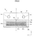
- FIG. 3 illustrates main characterizing portions of a stereo camera 1a according to the second embodiment and is a sectional view similar to FIG. 2 .
- the stereo camera 1a shown in FIG. 3 has a plurality of heat-generating components arranged on the circuit substrate 30.
- a CPU 301a, an FPGA 301b, and a power source IC 301c as the heat-generating components which are heat sources are arranged on the circuit substrate 30 of the stereo camera 1a.
- an interior space formed between the upper cover 201 and the lower cover 202 of the stereo camera 1a is filled with a filler 304a.
- the filler 304a is used instead of the TIM 304 in the first embodiment and promotes release of heat from the CPU 301a, the FPGA 301b, and the power source IC 301c.
- the contact position 210 is disposed on the center line D of the stereo camera 1a.
- the center line D is a line which is on the Y-Z plane including the center axis C of the camera stay 10 shown in FIG. 1 and which passes through the middle point of the distance in the X axis direction of the two imaging devices 100 disposed on the X-Y plane.
- the center line D is a symmetrical axis when setting each of normal lines of image planes of the two image sensors 102 as a line symmetrical axis. That is to say, the contact position 210 is disposed in a position which is farthest from the two lenses 101 of the imaging devices 100 and is equally far from each of the two lenses 101 of the image sensors 102.
- the stereo camera 1a is configured such that, even if the plurality of heat sources are randomly arranged, a route that transfers heat from each heat source, that is, a heat transfer route is limited and the heat from the heat sources is transferred to the contact position 210 which is disposed on the center line D of the stereo camera 1a and is equally far from each of the two lenses 101 of the image sensors 102. Thereby, heat distribution to the camera stay 10 is even, and heat transferred to the two lenses 101 and the two image sensors 102 is also even. Accordingly, the stereo camera is prevented the parallel relationship between the optical axes Lx of the lenses 101 from deteriorating and variation in characteristics of the image sensors 102 can be reduced. As a result, the stereo camera 1a can exactly execute the calculation of the distance.
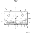
- FIG. 4 illustrates main characterizing portions of a stereo camera 1b according to the third embodiment and is a sectional view similar to FIG. 2 .
- the stereo camera 1b includes a plurality of heat sources.
- the CPU 301a, the FPGA 301b, and the power source IC 301c as the heat sources are arranged on the circuit substrate 30.
- a first TIM 304a, a second TIM 304b, and a third TIM 304c as thermal interface materials are attached to the CPU 301a, the FPGA 301b, and the power source IC 301c as the heat sources, respectively to promote release of heat from the heat sources
- a heat transfer component 42 as a heat transfer device includes a plate-shaped portion having a flat surface and a projection 421 provided on a center portion of an upper surface of the plate-shaped portion to have a projecting shape in section.
- a lower surface of the heat transfer component 42 is brought in contact with all of the heat sources and the thermal interface materials.
- an upper surface of the projection 421 of the heat transfer component 42 is brought in contact with a position corresponding to the contact position 210.
- the contact position 210 is disposed on the center line D of the stereo camera 1a.
- the center line D is in the same position as the center lines D in the stereo cameras 1 and so on according to the first and second embodiments as described above. Accordingly, the contact position 210 is disposed in a position which has an equal distance and is farthest from the two lenses 101 and the image sensors 102.
- Heat from the CPU 301a, the FPGA 301b, and the power source IC 301c is transferred to the heat transfer component 42 through the first TIM 304a, the second TIM 304b, and the third TIM 304c. Heat transferred to the heat transfer component 42 is transferred to a position of the upper cover 201 corresponding to the contact position 210 through the limitation of the heat transfer route by the projection 421.
- the heat released from each heat source is collected from the plate-shaped portion of the heat transfer component 42 to the projection 421 and is limited to be transferred from the projection 421 to the contact position 210. Thereby, the heat distribution of the entirety of the stereo camera 1b becomes even.
- the stereo camera 1b can exactly execute the calculation of the distance.
- FIG. 5 illustrates main characterizing portions of a stereo camera 1c according to the fourth embodiment and is a sectional view similar to FIG. 2 .
- the camera stay 10 and the upper cover 201 are separated.
- the camera stay 10 and the upper cover 201 are connected through a connector 43.
- a heat transfer device is formed by the connector 43 and the upper cover 201.
- a space 431 corresponding to a height of the connector 43 is provided between the upper cover 201 and the camera stay 10 by the connector 43.
- the connector 43 is disposed at a center in a width direction of the camera stay 10 and the upper cover 201, if the width direction is an arranged direction of the lenses 101.
- the center in the width direction is on the same axis as the center of the camera stay 10 and the upper cover 201. Note that a dimension of the connector 43 in the width direction is equal to half or less than half of a width dimension of the camera stay 10 or the upper cover 201.
- the CPU 301 of the heat source is brought in contact with the upper cover 201 through the TIM 304 of the thermal interface material. A part of heat transferred from the CPU 301 to the upper cover 201 is released out of the stereo camera 1c passing through the space 431.
- a heat transfer route of a part of the heat from the CPU 301 is limited by the connector 43.
- the connector 43 is disposed on a center line D of the stereo camera 1c. Note that the center line D is on the same position as the center line D of the stereo camera 1 and so on, in the first to third embodiments as described above. Accordingly, even in the fourth embodiment, the contact position 210 is in a position which has an equal distance and is farthest from the two lenses 101 and the two image sensors 102.
- the connector 43 is positioned at a central portion of the upper cover 201.
- the stereo camera 1c even if the CPU 301 of the heat source is disposed on a circumferential portion of the circuit substrate 30, the heat from the CPU 301 is transferred to the camera stay 10 through the connector 43. In other words, the heat from the CPU 301 is evenly transferred to the two lenses 101 and the two image sensors 102 through the connector 43. Therefore, it is possible to prevent the deterioration of the parallel relationship between the optical axes Lx of the lenses 101 due to the heat and reduce the variation in the characteristics of the image sensors 102 by the heat. As a result, the stereo camera 1c can exactly execute the calculation of the distance.
- the vehicle control unit is mounted on a vehicle, and calculates a distance to an object existing in a travelling direction of the vehicle and controls movement of the vehicle in accordance with the distance, by use of one of the stereo cameras 1a to 1c as described above.
- the lenses 101 of the stereo camera 1 are provided on the vehicle 500 to be capable of photographing a scene in front of the vehicle 500 in the traveling direction.
- the stereo camera 1 is mounted close to an inner rear view mirror of an inner upper portion (vehicle interior side) of a windshield of the vehicle 500.
- a mounted position of the stereo camera 1 is not limited to the above-mentioned position and may be mounted at a position capable of detecting circumstances outside the vehicle in front of the vehicle 500 in the traveling direction.
- the stereo camera 1 may be mounted on an object where a distance to a target to be measured changes.
- the stereo camera 1 is not limited to the use for the vehicle 500 and can be mounted on moving bodies such as ships, trains, or fixing bodies such as building in a case of being used for factory automation (FA).
- the stereo camera 1 obtains a distance to a subject (measured object) to be photographed from image data including the photographed subject (acquiring distance information).
- the measured object of the stereo camera 1 corresponds to other moving body, a person(s), an animal(s) and so on.
- the vehicle control unit 300 includes the stereo camera 1 provided in the vehicle interior which is a room space, a control device 310, a steering wheel 320, and a brake pedal 330, as shown in FIG. 6 .
- the stereo camera 1 has a function of photographing the travelling direction of the vehicle 500 and is disposed close to the rear view mirror provided above the windshield of the vehicle 500, for example.
- the control device 310 of the vehicle control unit 300 executes various vehicle controls by the distance information from the stereo camera 1 to the subject, acquired based on the parallax image received from the stereo camera 1.
- the control device 310 executes steering control to avoid an obstacle by controlling a steering system (controlled object) including the steering wheel 320 based on the parallax image received from the stereo camera 1, as an example of the vehicle controls.
- the control device 310 executes brake control and so on causing the vehicle 500 to decelerate and stop by controlling the brake pedal 330 (controlled object) based on the parallax image received from the stereo camera 1.
- the vehicle control such as the steering control or the break control is executed, and hence safety of driving of the vehicle 500 can be improved.
- the stereo camera 1 is configured to photograph the front of the vehicle 500, but is not limited to this.
- the stereo camera 1 may be disposed to photograph a rear or side of the vehicle 500.
- the stereo camera 1 can detect a position of a following vehicle in the rear of the vehicle 500 or other vehicle travelling parallel to the side of the vehicle 500.
- the control device 310 can execute the above-mentioned vehicle control by detecting a risk when changing in a vehicle lane or entering a merging lane of the vehicle 500.
- control device 310 can execute the above-mentioned vehicle control in a case where it is determined to have a risk that the vehicle 500 collides with an obstacle which exists in rear of the vehicle 500 and is detected by the stereo camera 1 in the back movement of the vehicle 500 at the time of parking the vehicle 500, based on parallax image of the obstacle.
- the stereo camera 1 inter-connecting with the vehicle control unit 300 is disposed in a position of the vehicle 500 where easily gets direct sunlight and so on.
- the entirety of the stereo camera 1 is irradiated with the direct sunlight and so on. Therefore, the deviation of the heat distribution of the stereo camera does not occur, differing from the heat from the particular components on the circuit substrate 30.
- the vehicle control unit 300 can prevent the heat distribution to the camera stay 10 from becoming uneven by the heat from the heat-generating components inside the stereo camera 1, by the effects of the heat transfer component 40 of the heat transfer device and so on. Thereby, the heat distribution of the camera stay 10 becomes even and therefore the distance can be accurately calculated. As a result, the vehicle control unit 300 can more exactly execute the control of the vehicle 500.
Landscapes
- Engineering & Computer Science (AREA)
- Physics & Mathematics (AREA)
- General Physics & Mathematics (AREA)
- Microelectronics & Electronic Packaging (AREA)
- Multimedia (AREA)
- Aviation & Aerospace Engineering (AREA)
- Signal Processing (AREA)
- Thermal Sciences (AREA)
- Radar, Positioning & Navigation (AREA)
- Remote Sensing (AREA)
- Automation & Control Theory (AREA)
- Electromagnetism (AREA)
- Mechanical Engineering (AREA)
- Theoretical Computer Science (AREA)
- Measurement Of Optical Distance (AREA)
- Studio Devices (AREA)
Abstract
Description
- The present invention relates to an imaging unit capable of calculating a distance to a subject by imaging a three-dimensional image, a vehicle control unit using the imaging unit, and a heat transfer method for the imaging unit.
- A so-called stereo camera is known as an imaging unit capable of calculating a distance to a target object, as eyes of a person. The stereo camera includes two monocular cameras. For example, the stereo camera is inter-connected with a vehicle control unit that controls a vehicle and configured to calculate a distance to a subject in front of the vehicle. As a result, the stereo camera can control operation of the vehicle depending on the calculated distance.
- The two molecular cameras of the stereo camera are disposed on the same plane and fixed such that both optical axes of the cameras are parallel to each other. The stereo camera detects a parallax quantity of the subject by simultaneously imaging the same subject by the two molecular cameras and can calculate a distance to the subject based on the parallax quantity.
- There is a plurality of important factors to calculate a distance by use of the stereo camera. It is important that a standard length which corresponds to a distance between the optical axes of the two monocular cameras is set to a predetermined value, and focal lengths of the two monocular cameras are configured to match with each other. Furthermore, it is also important that the optical axes of the two monocular cameras are maintained parallel. If one monocular camera is directed to a different direction from the other, the optical axes are not maintained parallel to each other. In such a state, the parallax quantity cannot be exactly detected. If the parallax quantity cannot be exactly detected, the distance to the subject cannot be exactly calculated, accordingly.
- Therefore, it is important that the stereo camera has the same focal length so as to fit characteristics of lenses used for the two monocular cameras and the standard length continues to be maintained to have a designed value, so that the stereo camera calculates an exact distance. Moreover, it is important that parallelism of the optical axes of the two monocular cameras is set in a correct state at the time of assembling them and maintained in that state thereafter.
- However, the important factors as described above are often changed depending on a sequential change in situation in installation environment of the stereo camera. That is to say, by the sequential change, a fixed portion of each monocular camera is deformed to become a state where directions (positions) of the monocular cameras differ from each other. Therefore, the parallelism of the optical axes is not maintained, or performance of each monocular camera is reduced by a change in temperature environment.
- Therefore, a method of mounting a vehicle-mounted camera to hold a position of two monocular cameras is known (for example, see Japanese Patent No.
3877475 - As shown in the vehicle-mounted camera disclosed in Japanese Patent No.
3877475 - In particular, in the stay made of a metal as shown in the vehicle-mounted camera disclosed in Japanese Patent No.
3877475 - The present invention is made in view of the above and an object of the present invention is to provide an imaging unit capable of eliminating the occurrence of operation failure by the deviation of heat distribution in a stereo camera.
- To accomplish the above object, an imaging unit according to one embodiment of the present invention includes two imaging devices, a substrate holder that holds a circuit substrate on which a component regarding operation of the two imaging devices is disposed, and a heat transfer device that transfers heat generated in the component to the substrate holder. One end of the heat transfer device is brought in contact with the component and other end of the heat transfer device is brought in contact with the substrate holder on a line having an equal distance from each of image pick-up devices of the two imaging devices.
- According to the configuration, it is possible to restrain the occurrence of operation failure by the deviation of heat distribution in the stereo camera.
-
FIG. 1 is an exploded perspective view showing an outline of a stereo camera of one embodiment of an imaging unit according to the present invention. -
FIG. 2 is a partial sectional view taken along line A-A' ofFIG. 1 showing one example of an inner structure of a main part of the imaging unit. -
FIG. 3 is a partial sectional view taken along line A-A' ofFIG. 1 showing other example of the inner structure of the main part of the imaging unit. -
FIG. 4 is a partial sectional view taken along line A-A' ofFIG. 1 showing further other example of the inner structure of the main part of the imaging unit. -
FIG. 5 is a partial sectional view taken along line A-A' ofFIG. 1 showing still other example of the inner structure of the main part of the imaging unit. -
FIG. 6 is a schematic diagram showing one embodiment of a vehicle control unit according to the present invention. - Embodiments of the present invention will be described hereinafter with reference to the accompanying drawings. A first embodiment is first described. As illustrated in
FIG. 1 , astereo camera 1 as an imaging unit includes acamera stay 10 which is an imaging device holder which holds twoimaging devices 100 and asubstrate holder 20 to which the camera stay 10 is fixed. Each of the twoimaging devices 100 includes alens 101, animage sensor 102, and asensor substrate 103. Note that the camera stay 10 and thesubstrate holder 20 are integrally formed in the first embodiment. - Here, axes in a three-dimensional perpendicular coordinate system using when explaining a structure of the
stereo camera 1 are defined as follows. As shown inFIG. 1 , an X axis extends to a direction where thelenses 101 are arranged. A Z axis extends to a normal direction of a direction where eachimage sensor 102 images an image. A Y axis extends to a height direction of the stereo camera perpendicular to the X axis and the Z axis. - Each of the
lenses 101 of the imaging devices is fitted in an opening 10a provided in a front portion of the camera stay 10. An optical axis Lx of eachlens 101 has a standard length which is secured in a state where each lens is fitted in the opening and required for distance calculation. Moreover, the optical axis Lx of eachlens 101 is held in a state parallel to the Z axis and directed to the same direction as the Z axis. - The
image sensor 102 is disposed in a back surface side of eachlens 101, that is, in the Z axis direction. The optical axis Lx of eachlens 101 and a center of an imaging surface of eachimage sensor 102 are configured to coincide with each other. Each of theimage sensors 102 is composed of an image pick-up device fixed to aseparate sensor substrate 103. Each of theimage sensors 102 outputs a signal regarding the subject imaged on the imaging surface through thecorresponding lens 101. - In this case, the
imaging device 100 is configured to fit thelenses 101 in theopenings 10a of the front surface of the camera stay 10 and fix theimage sensors 102 according to the optical axes Lx of thelenses 101. As a result, theimaging devices 100 detect a parallax quantity from images picked up by the twoimage sensors 102 and therefore a distance calculation can be achieved. - To correctly fix the two
lenses 101 by the standard length which is one of important elements to correctly execute the distance calculation, thelenses 101 must be accurately maintained in a predetermined position and a predetermined arrangement. To do so, it is needed that, for example, an abutting surface of the camera stay 10 to eachlens 101 is accurately worked and an abutting portion of eachlens 101 to thecamera stay 10 is accurately worked. Positions and dimensions of the holes to fit thelenses 101 in thecamera stay 10 are correctly worked so as to accurately position thelenses 101. Note that it is preferable to use lenses having the same optical characteristic to fit to a focal length which is one of the important elements required for the distance calculation. In addition, regarding theimage sensors 102 which influence a camera characteristic, it is preferable to use image sensors having the same optical characteristic. - To accurately execute the distance calculation, the parallelism of the optical axes Lx must be maintained. To maintain the parallelism, it is important to accurately work an abutment surface of the
camera stay 10 to eachlens 101 and an abutment surface of thelens 101 to thecamera stay 10. In addition, the parallelism of the optical axes Lx of the twolenses 101 can be maintained even by accurately working the holes of thecamera stay 10. - The
substrate holder 20 includes anupper cover 201 and alower cover 202. Thecamera stay 10 is fixed to theupper cover 201. Note that theupper cover 201 and thecamera stay 10 may be integrally configured. Thelower cover 202 has a concave shape in section as a tray. - The
circuit substrate 30 is disposed and held in a space formed between theupper cover 201 and the lower cover 202 (seeFIG. 1 ). Components relating to operation of theimaging device 100 such as calculation elements that calculate a distance based on control of operation of theimaging devices 100 and a parallax quantity between two images imaged by the imaging devices, and elements for controlling a light source are arranged on thecircuit substrate 30. Heat-generating components generating a high temperature are included in these components. The heating component exemplified inFIG. 1 is a central processing unit (hereinafter referred to as CPU) 301. As shown inFIG. 1 , amemory 302 used for the processing of theCPU 301, apower source section 303 that supplies an operation current to theCPU 301, and so on are arranged on thecircuit substrate 30. Note that wirings (not shown) are provided between thecircuit substrate 30 and each of theimaging devices 100. - In the following description, the
CPU 301 only is described as the heating component in thestereo camera 1 according to the embodiment. It should be understood that the heating component is not limited to theCPU 301. For example, other components such as a field programmable gate array (FPGA), a power source-integrated circuit (IC), and so on correspond to the heat-generating components. When a plurality of heat-generating components is arranged on thecircuit substrate 30, aheat transfer component 40 may be provided on each heating component (seeFIGs. 1 and2 ), as described below. - The heat-generating components mean components that release heat in surroundings during the operation. For example, the heating component such as the
CPU 301 tends to generate abnormal operation due to thermal runaway when it cannot release heat. Therefore, a thermal interface material 304 (hereinafter referred to as TIM) to promote the heat release is attached to the CPU 301 (seeFIG. 1 ). - The
stereo camera 1 includes theheat transfer component 40 which is a heat transfer device to limit a heat transfer route from theCPU 301. Theheat transfer component 40 is provided on an upper surface of the TIM 304 (seeFIGs. 1 and2 ). One end of theheat transfer component 40 is brought in contact with theTIM 304 to collect heat. Aprotrusion 401 is provided on the other end of theheat transfer component 40. Theprotrusion 401 is brought in contact with theupper cover 201 and is configured to limit the heat transfer route. Here, theheat transfer component 40 can be formed by a heat pipe, for example. - The
TIM 304 is formed by a structure having high heat conductivity. In other words, it is preferable that a material of the TIM has high heat conductivity. For example, theTIM 304 is formed by working a heat pipe, graphite sheet, or thin steel plate. One surface, that is, a lower surface of theTIM 304 comes in contact with theCPU 301 to collect heat, and the other end, that is, the upper surface of theTIM 304 comes in contact with the heat transfer component 40 (seeFIG. 2 ). Note that the one end of theheat transfer component 40 may be configured to come in contact with theCPU 301 directly. If theheat transfer component 40 is formed by the graphite, the fixation of theheat transfer component 40 to theCPU 301 can be performed by a double sided tape and so on. - As described above, the one end of the
heat transfer component 40 is configured to come in contact with theTIM 304. Theprotrusion 401 provided on the other end of theheat transfer component 40 limits the heat transfer rout of heat and is configured to be in contact with theupper cover 201, as described above. A position of theupper cover 201, with which theprotrusion 401 of the other end of theheat transfer component 40 comes in contact is acontact position 210 as shown inFIG. 1 , for example. Thecontact position 210 is a position which is farthest from the twoimaging devices 100 and has an equal distance from each of the twolenses 101 or theimage sensors 102, in theupper cover 201. - Heat released from the
CPU 301 is transferred to thecontact position 210 of theupper cover 201 through theheat transfer component 40 in a state where the heat transfer route is limited. Thereby, heat inside thesubstrate holder 20 is transferred to thecontact position 210 which is disposed in the predetermined position of theupper cover 201, and diffused throughout the entirety of theupper cover 201 from the contact position. Accordingly, even if theCPU 301 of the heat source is disposed in a deviated position on theentire stereo camera 1, it is possible to equalize heat distribution of the entirety of thestereo camera 1 by theheat transfer component 40 that limits the heat transfer route from the heat source of the deviated position. - Next, a detailed structure regarding the
stereo camera 1 is described.FIG. 2 is a sectional view taken along line A-A' of thestereo camera 1 shown inFIG. 1 and illustrates an inner structure of thesubstrate holder 20 which is a main characterizing part of thestereo camera 1. - As shown in
FIG. 2 , theTIM 304 is disposed on theCPU 301 disposed on an upper surface of thecircuit substrate 30. Theheat transfer component 40 is further disposed on theTIM 304. - The
heat transfer component 40 is formed by a material having high heat conductivity. The one end of theheat transfer component 40 is configured to come in contact with theTIM 304 in a manner of surface contact. Theprotrusion 401 of the other end of theheat transfer component 40 is configured to come in contact with a position facing thecontact position 210 on an inner side surface of theupper cover 201. Theprotrusion 401 of theheat transfer component 40 has a quadrangle such that an area of a contact portion between theprotrusion 401 and theupper cover 201 becomes smaller than that of a contact portion between theprotrusion 401 and theTIM 304. Accordingly, the heat from the heat source, that is, theCPU 301 concentrates at theprotrusion 401. Note that the shape of the protrusion may be a column shape, triangle, or other polygonal columnar shape without being limited to the quadrangle as described above. - The contact position is disposed on a center line D of the stereo camera 1 (see
FIG. 2 ). The center line D is a line which is on a Y-Z plane including a center axis C of thecamera stay 10 shown inFIG. 1 and which passes through a middle point of a distance in the X axis direction of the twoimaging devices 100 disposed on an X-Y plane. In other words, the center line D is a symmetrical axis when setting each of normal lines of image planes of the twoimage sensors 102 as a line symmetrical axis. That is to say, the center line D is a line which is in an equal distance from each of theimage sensors 102. In other words, the center line D is parallel with a line perpendicular to each normal line of theimage sensors 102 and passing through a middle point between the normal lines of the twoimage sensors 102. That is, thecontact position 210 is disposed on a center of an axial symmetry in theimage sensors 102 of the twoimaging devices 100. - The
contact position 210 is positioned on an end portion in front of theupper cover 201, as described above. In other words, thecontact position 210 is in a position which is farthest from the twolenses 101 of the imaging devices of thestereo camera 1 and which is equally far from each of the twoimage sensors 102. In other words, thecontact position 210 is located on a line of an equal distance from each of the twoimage sensors 102. - Generally, the
CPU 301 is often disposed on a circumferential portion of the circuit substrate as shown inFIG. 2 . If theheat transfer component 40 as described above is not used, the heat is released by being in contact theTIM 304 with theupper cover 201 just above a portion (hereinafter referred to as disposed portion) where theCPU 301 is disposed, or the heat is released from theupper cover 201 through a space between theupper cover 201 and thelower cover 202. - If do so, the heat is transferred from the
upper cover 201 closest to the heat source, that is, theCPU 301 to the entirety of thestereo camera 1. Therefore, a portion of theupper cover 201 which is just above and close to the disposed portion of theCPU 301 has the highest temperature, and a heat distribution according to a distance from this portion having the highest temperature is formed. In this case, a heat distribution of the entirety of thestereo camera 1 becomes a state of deviating depending on a position of theCPU 301. As a result, if theheat transfer component 40 is not used, the heat distribution of thestereo camera 1 becomes uneven and a heat distribution of thecamera stay 10 also becomes uneven. - When the heat distribution of the
camera stay 10 becomes uneven, a temperature of each of thelens 101 and theimage sensor 102 closer to theCPU 301 of the heat source than theother lens 101 and theimage sensor 102, of the twolenses 101 and twoimage sensors 102, is higher than that of the other lens and image sensor. - If the
camera stay 10 is made of a metal member, when the deviation of the heat distribution as described above exists, thermal expansion occurs in the stay depending on it. Therefore, thecamera stay 10 is unevenly deformed. As a result, there is a possibility that a position of one oflenses 101 is deviated and the parallelism or alignment of the optical axes Lx cannot be correctly maintained. - When the position of the one of
lenses 101 is deviated and the parallelism of the optical axes Lx cannot be correctly maintained, a view angle or focal position of each of the two images picked up by the twoimaging devices 100 is not normal. Therefore, a distance to a subject cannot be calculated. In addition, when only one of theimage sensors 102 becomes a high temperature, uniformity of characteristics of the twoimage sensors 102 is broken. Thereby, it is not possible to exactly calculate the distance. Furthermore, one of theimage sensors 102 having a temperature higher than the other image sensor easily breaks in comparison to the other image sensor. - Therefore, by providing the
heat transfer component 40 on thestereo camera 1, as described in the embodiment, even if theCPU 301 of the heat source is disposed on the circumferential portion of thecircuit substrate 30, the heat transfer route is configured to integrate on a center portion between the twoimaging devices 100. Thereby, a transfer position of heat is limited. As a result, it is possible to equalize the heat distribution of the entirety of thestereo camera 1. - In other words, a position of only one of the
lenses 101 of thestereo camera 1 can be prevented from deviating from a correct position. In addition, it is possible to maintain the parallelism of the optical axes Lx of thelenses 101 and prevent the parallelism of the optical axes from deteriorating. Moreover, it is possible to prevent only one of the lenses from becoming a high temperature. As a result, it is possible to exclude a bad influence on calculation accuracy of the distance and to enhance reliability of thestereo camera 1 by preventing the lenses from being easily broken. Note that the heat transfer route may be configured to be substantially concentrated at the center portion between twoimaging devices 100. However, in particular, it is prefer to concentrate the heat transfer route at a center portion between theimage sensors 102 which easily receive influence of heat. - A method of transferring the heat of the
stereo camera 1 described above is as follows. The camera stay 10 that holds the twoimaging devices 100 is first fixed to thesubstrate holder 20 that holds thecircuit substrate 30. Next, the one end of theheat transfer component 40 is brought in contact with theCPU 301 which is the heating component disposed on thecircuit substrate 30. Thereafter, the other end of theheat transfer component 40 is brought in contact with the inner side surface of thesubstrate holder 20 at thecontact position 210 that lies at the equal distance from each of the twoimage sensors 102. Thereby, the heat of the heating component disposed inside thestereo camera 1 is transferred to a predetermined position of thestereo camera 1. - Next, a second embodiment of the imaging unit is described.
FIG. 3 illustrates main characterizing portions of a stereo camera 1a according to the second embodiment and is a sectional view similar toFIG. 2 . - The stereo camera 1a shown in
FIG. 3 has a plurality of heat-generating components arranged on thecircuit substrate 30. ACPU 301a, anFPGA 301b, and apower source IC 301c as the heat-generating components which are heat sources are arranged on thecircuit substrate 30 of the stereo camera 1a. In addition, an interior space formed between theupper cover 201 and thelower cover 202 of the stereo camera 1a is filled with afiller 304a. Thefiller 304a is used instead of theTIM 304 in the first embodiment and promotes release of heat from theCPU 301a, theFPGA 301b, and thepower source IC 301c. - One end of a
heat transfer portion 41 as the heat transfer device is brought in contact with thefiller 304a and the other end of theheat transfer portion 41 is brought in contact with a position corresponding to thecontact position 210 of the upper cover 201 (seeFIG.3 ). Thecontact position 210 is disposed on the center line D of the stereo camera 1a. As described in the first embodiment, the center line D is a line which is on the Y-Z plane including the center axis C of thecamera stay 10 shown inFIG. 1 and which passes through the middle point of the distance in the X axis direction of the twoimaging devices 100 disposed on the X-Y plane. In other words, the center line D is a symmetrical axis when setting each of normal lines of image planes of the twoimage sensors 102 as a line symmetrical axis. That is to say, thecontact position 210 is disposed in a position which is farthest from the twolenses 101 of theimaging devices 100 and is equally far from each of the twolenses 101 of theimage sensors 102. - The stereo camera 1a is configured such that, even if the plurality of heat sources are randomly arranged, a route that transfers heat from each heat source, that is, a heat transfer route is limited and the heat from the heat sources is transferred to the
contact position 210 which is disposed on the center line D of the stereo camera 1a and is equally far from each of the twolenses 101 of theimage sensors 102. Thereby, heat distribution to thecamera stay 10 is even, and heat transferred to the twolenses 101 and the twoimage sensors 102 is also even. Accordingly, the stereo camera is prevented the parallel relationship between the optical axes Lx of thelenses 101 from deteriorating and variation in characteristics of theimage sensors 102 can be reduced. As a result, the stereo camera 1a can exactly execute the calculation of the distance. - Next, a third embodiment of the imaging unit is described.
FIG. 4 illustrates main characterizing portions of astereo camera 1b according to the third embodiment and is a sectional view similar toFIG. 2 . - As shown in
FIG. 4 , thestereo camera 1b includes a plurality of heat sources. TheCPU 301a, theFPGA 301b, and thepower source IC 301c as the heat sources are arranged on thecircuit substrate 30. Afirst TIM 304a, asecond TIM 304b, and athird TIM 304c as thermal interface materials are attached to theCPU 301a, theFPGA 301b, and thepower source IC 301c as the heat sources, respectively to promote release of heat from the heat sources - A
heat transfer component 42 as a heat transfer device includes a plate-shaped portion having a flat surface and aprojection 421 provided on a center portion of an upper surface of the plate-shaped portion to have a projecting shape in section. A lower surface of theheat transfer component 42 is brought in contact with all of the heat sources and the thermal interface materials. On the other hand, an upper surface of theprojection 421 of theheat transfer component 42 is brought in contact with a position corresponding to thecontact position 210. Thecontact position 210 is disposed on the center line D of the stereo camera 1a. Here, the center line D is in the same position as the center lines D in thestereo cameras 1 and so on according to the first and second embodiments as described above. Accordingly, thecontact position 210 is disposed in a position which has an equal distance and is farthest from the twolenses 101 and theimage sensors 102. - Heat from the
CPU 301a, theFPGA 301b, and thepower source IC 301c is transferred to theheat transfer component 42 through thefirst TIM 304a, thesecond TIM 304b, and thethird TIM 304c. Heat transferred to theheat transfer component 42 is transferred to a position of theupper cover 201 corresponding to thecontact position 210 through the limitation of the heat transfer route by theprojection 421. - In the
stereo camera 1b, even if the plurality of heat sources are randomly arranged, the heat released from each heat source is collected from the plate-shaped portion of theheat transfer component 42 to theprojection 421 and is limited to be transferred from theprojection 421 to thecontact position 210. Thereby, the heat distribution of the entirety of thestereo camera 1b becomes even. - If that is done, because the heat distribution to the
camera stay 10 becomes also even, heat transferred to the twolenses 101 and the twoimage sensors 102 becomes also even. Therefore, it is possible to prevent the deterioration of the parallel relationship between the optical axes Lx of thelenses 101 due to the heat and reduce the variation in the characteristics of theimage sensors 102 due to the heat. Thereby, thestereo camera 1b can exactly execute the calculation of the distance. - Next, a fourth embodiment of the imaging device is described.
FIG. 5 illustrates main characterizing portions of astereo camera 1c according to the fourth embodiment and is a sectional view similar toFIG. 2 . - As shown in
FIG. 5 , in thestereo camera 1c according to the fourth embodiment, thecamera stay 10 and theupper cover 201 are separated. Thecamera stay 10 and theupper cover 201 are connected through aconnector 43. In thestereo camera 1c according to the fourth embodiment, a heat transfer device is formed by theconnector 43 and theupper cover 201. Aspace 431 corresponding to a height of theconnector 43 is provided between theupper cover 201 and thecamera stay 10 by theconnector 43. - The
connector 43 is disposed at a center in a width direction of thecamera stay 10 and theupper cover 201, if the width direction is an arranged direction of thelenses 101. The center in the width direction is on the same axis as the center of thecamera stay 10 and theupper cover 201. Note that a dimension of theconnector 43 in the width direction is equal to half or less than half of a width dimension of thecamera stay 10 or theupper cover 201. - In the
stereo camera 1c, theCPU 301 of the heat source is brought in contact with theupper cover 201 through theTIM 304 of the thermal interface material. A part of heat transferred from theCPU 301 to theupper cover 201 is released out of thestereo camera 1c passing through thespace 431. - Here, a heat transfer route of a part of the heat from the
CPU 301 is limited by theconnector 43. Theconnector 43 is disposed on a center line D of thestereo camera 1c. Note that the center line D is on the same position as the center line D of thestereo camera 1 and so on, in the first to third embodiments as described above. Accordingly, even in the fourth embodiment, thecontact position 210 is in a position which has an equal distance and is farthest from the twolenses 101 and the twoimage sensors 102. Here, for example, theconnector 43 is positioned at a central portion of theupper cover 201. - As in the
stereo camera 1c, even if theCPU 301 of the heat source is disposed on a circumferential portion of thecircuit substrate 30, the heat from theCPU 301 is transferred to thecamera stay 10 through theconnector 43. In other words, the heat from theCPU 301 is evenly transferred to the twolenses 101 and the twoimage sensors 102 through theconnector 43. Therefore, it is possible to prevent the deterioration of the parallel relationship between the optical axes Lx of thelenses 101 due to the heat and reduce the variation in the characteristics of theimage sensors 102 by the heat. As a result, thestereo camera 1c can exactly execute the calculation of the distance. - As described above, in each embodiment, because the deviation of the heat transferred to the
camera stay 10 is not generated, a heat distribution to thelenses 101 composed of two monocular lenses and theimage sensors 102 becomes also even. Thereby, it is possible to prevent a relative position of thelenses 101 from being changed depending on time and maintain the parallelism of the optical axes Lx. In addition, the deviation of the heat in theimage sensors 102 is not generated and the characteristics of the image sensors are not changed even by a change on standing due to the heat. Thereby, it is possible to eliminate a variation difference between two images as imaged and can exactly execute distance calculation by a parallax quantity between the two images. - Next, a vehicle control unit according to an embodiment of the present invention is described. The vehicle control unit is mounted on a vehicle, and calculates a distance to an object existing in a travelling direction of the vehicle and controls movement of the vehicle in accordance with the distance, by use of one of the stereo cameras 1a to 1c as described above.
- As shown in
FIG. 6 , thelenses 101 of thestereo camera 1 are provided on thevehicle 500 to be capable of photographing a scene in front of thevehicle 500 in the traveling direction. Thestereo camera 1 is mounted close to an inner rear view mirror of an inner upper portion (vehicle interior side) of a windshield of thevehicle 500. A mounted position of thestereo camera 1 is not limited to the above-mentioned position and may be mounted at a position capable of detecting circumstances outside the vehicle in front of thevehicle 500 in the traveling direction. - The
stereo camera 1 may be mounted on an object where a distance to a target to be measured changes. Thestereo camera 1 is not limited to the use for thevehicle 500 and can be mounted on moving bodies such as ships, trains, or fixing bodies such as building in a case of being used for factory automation (FA). Thestereo camera 1 obtains a distance to a subject (measured object) to be photographed from image data including the photographed subject (acquiring distance information). The measured object of thestereo camera 1 corresponds to other moving body, a person(s), an animal(s) and so on. - The
vehicle control unit 300 includes thestereo camera 1 provided in the vehicle interior which is a room space, acontrol device 310, asteering wheel 320, and abrake pedal 330, as shown inFIG. 6 . Thestereo camera 1 has a function of photographing the travelling direction of thevehicle 500 and is disposed close to the rear view mirror provided above the windshield of thevehicle 500, for example. - Here, a relationship between the
stereo camera 1 and thevehicle control unit 300 is described. Thecontrol device 310 of thevehicle control unit 300 executes various vehicle controls by the distance information from thestereo camera 1 to the subject, acquired based on the parallax image received from thestereo camera 1. - The
control device 310 executes steering control to avoid an obstacle by controlling a steering system (controlled object) including thesteering wheel 320 based on the parallax image received from thestereo camera 1, as an example of the vehicle controls. In addition, thecontrol device 310 executes brake control and so on causing thevehicle 500 to decelerate and stop by controlling the brake pedal 330 (controlled object) based on the parallax image received from thestereo camera 1. With such astereo camera 1 and avehicle control unit 300 including thecontrol device 310, the vehicle control such as the steering control or the break control is executed, and hence safety of driving of thevehicle 500 can be improved. - As described above, the
stereo camera 1 is configured to photograph the front of thevehicle 500, but is not limited to this. For example, thestereo camera 1 may be disposed to photograph a rear or side of thevehicle 500. In this case, thestereo camera 1 can detect a position of a following vehicle in the rear of thevehicle 500 or other vehicle travelling parallel to the side of thevehicle 500. Thecontrol device 310 can execute the above-mentioned vehicle control by detecting a risk when changing in a vehicle lane or entering a merging lane of thevehicle 500. - In addition, the
control device 310 can execute the above-mentioned vehicle control in a case where it is determined to have a risk that thevehicle 500 collides with an obstacle which exists in rear of thevehicle 500 and is detected by thestereo camera 1 in the back movement of thevehicle 500 at the time of parking thevehicle 500, based on parallax image of the obstacle. - As described above, the
stereo camera 1 inter-connecting with thevehicle control unit 300 is disposed in a position of thevehicle 500 where easily gets direct sunlight and so on. The entirety of thestereo camera 1 is irradiated with the direct sunlight and so on. Therefore, the deviation of the heat distribution of the stereo camera does not occur, differing from the heat from the particular components on thecircuit substrate 30. - From the above description, the
vehicle control unit 300 can prevent the heat distribution to the camera stay 10 from becoming uneven by the heat from the heat-generating components inside thestereo camera 1, by the effects of theheat transfer component 40 of the heat transfer device and so on. Thereby, the heat distribution of thecamera stay 10 becomes even and therefore the distance can be accurately calculated. As a result, thevehicle control unit 300 can more exactly execute the control of thevehicle 500. - Although the present invention has been described in terms of exemplary embodiments, it is not limited thereto. It should be appreciated that variations may be made in the embodiments described by persons skilled in the art without departing from the scope of the present invention as defined by the following claims.
Claims (10)
- An imaging unit (1) comprising:two imaging devices (100);a substrate holder (20) that holds a circuit substrate (30) on which a component (301) regarding operation of the two imaging devices is disposed; anda heat transfer device (40) that transfers heat generated in the component to the substrate holder (20),characterized in that one end of the heat transfer device (40) is brought in contact with the component (301) and other end of the heat transfer device (40) is brought in contact with the substrate holder (20) on a line having an equal distance from each of image pick-up devices (102) of the two imaging devices (100).
- The imaging unit according to claim 1, characterized in that the other end of the heat transfer device (40) is brought in contact with an end portion of the substrate holder (20) remote from the imaging devices (100).
- The imaging unit according to claim 1, characterized in that the heat transfer device (40) is formed by a heat pipe.
- The imaging unit according to claim 1, characterized by further comprising an imaging device holder (10) that holds the two imaging devices (100), and
characterized in that the imaging device holder (10) and the substrate holder (20) each are formed by a metal member. - The imaging unit according to claim 1, characterized by further comprising an imaging device holder (10) that holds the two imaging devices (100),
characterized in that the imaging device holder (10) and the substrate holder (20) are connected by a connector (43), and the connector is positioned at a center portion of the imaging device holder (10). - The imaging unit according to claim 5, characterized in that a space (431) corresponding to a height of the connector (43) is provided between the imaging device holder (10) and the substrate holder (20).
- The imaging unit according to claim 5, characterized in that the connector (43) has a width dimension set to be equal to half or less than half of that of the imaging device holder (10) or the substrate holder (20).
- A vehicle control unit (300) comprising:a unit which is mounted on a vehicle (500) and calculates a distance to an object existing in a travelling direction of the vehicle (500),characterized in that the unit is the imaging unit (1) claimed in any one of claims 1 to 7.
- A heat transfer method for an imaging unit configured to transfer heat of a component (301) regarding operation of an imaging unit (1) having two imaging devices (100) to the imaging unit,
characterized by comprising:coming in contact one end of a heat transfer device (40) that transfers the heat to a substrate holder (20) that holds a circuit substrate (30) on which the component (301) is disposed with the component; andcoming in contact other end of the heat transfer device (40) with an inner side of the substrate holder (20) existing on a line having an equal distance from each of two image pick-up devices (102) of the imaging unit (1) to transfer the heat from the other end of the heat transfer device (40) to the two image pick-up devices (102) on the line of the equal distance. - An imaging unit comprising:two imaging devices (100);a substrate holder (20) that holds a circuit substrate (30) on which a component (301) regarding operation of the two imaging devices (100) is disposed; anda heat transfer device (40) that transfers heat generated in the component to the substrate holder (20),characterized in that one end of the heat transfer device (40) is brought in contact with the component (301) and other end of the heat transfer device (40) is brought in contact with the substrate holder (20) on a line having an equal distance from each of image pick-up devices (102) of the two imaging devices (100).
Applications Claiming Priority (2)
| Application Number | Priority Date | Filing Date | Title |
|---|---|---|---|
| JP2015055180 | 2015-03-18 | ||
| JP2015240799A JP6627471B2 (en) | 2015-03-18 | 2015-12-10 | Imaging unit, vehicle control unit, and heat transfer method of imaging unit |
Publications (2)
| Publication Number | Publication Date |
|---|---|
| EP3070524A1 true EP3070524A1 (en) | 2016-09-21 |
| EP3070524B1 EP3070524B1 (en) | 2020-01-01 |
Family
ID=55913438
Family Applications (1)
| Application Number | Title | Priority Date | Filing Date |
|---|---|---|---|
| EP16161088.6A Active EP3070524B1 (en) | 2015-03-18 | 2016-03-18 | Imaging unit, vehicle control unit and heat transfer method for imaging unit |
Country Status (2)
| Country | Link |
|---|---|
| US (1) | US10412274B2 (en) |
| EP (1) | EP3070524B1 (en) |
Cited By (2)
| Publication number | Priority date | Publication date | Assignee | Title |
|---|---|---|---|---|
| WO2021019349A1 (en) * | 2019-07-30 | 2021-02-04 | Ricoh Company, Ltd. | Capturing unit and vehicle control unit |
| US20230367325A1 (en) * | 2022-05-10 | 2023-11-16 | Ghost Autonomy Inc. | Controlling camera sensor operating temperatures in an autonomous vehicle |
Families Citing this family (4)
| Publication number | Priority date | Publication date | Assignee | Title |
|---|---|---|---|---|
| JP2019174781A (en) | 2017-08-24 | 2019-10-10 | キヤノン株式会社 | Catoptric element and stereo camera device |
| US10674305B2 (en) | 2018-03-15 | 2020-06-02 | Microsoft Technology Licensing, Llc | Remote multi-dimensional audio |
| US20190289396A1 (en) * | 2018-03-15 | 2019-09-19 | Microsoft Technology Licensing, Llc | Electronic device for spatial output |
| US11474417B2 (en) * | 2020-08-07 | 2022-10-18 | Lineage Logistics, LLC | Lens heater assembly for camera |
Citations (6)
| Publication number | Priority date | Publication date | Assignee | Title |
|---|---|---|---|---|
| JPH11301365A (en) * | 1998-04-17 | 1999-11-02 | Kyocera Corp | Supporting device for car stereo camera |
| EP1086859A1 (en) * | 1999-09-22 | 2001-03-28 | Fuji Jukogyo Kabushiki Kaisha | Structure for mounting cameras on a vehicle |
| US20060018509A1 (en) * | 2004-07-20 | 2006-01-26 | Takashi Miyoshi | Image generation device |
| US20070097249A1 (en) * | 2004-10-28 | 2007-05-03 | Tsuguhiro Korenaga | Camera module |
| JP2013127598A (en) * | 2011-11-17 | 2013-06-27 | Hitachi Automotive Systems Ltd | Stereo camera |
| US20140267621A1 (en) * | 2013-03-18 | 2014-09-18 | Fuji Jukogyo Kabushiki Kaisha | Stereo camera unit |
Family Cites Families (7)
| Publication number | Priority date | Publication date | Assignee | Title |
|---|---|---|---|---|
| EP2357527B1 (en) | 2004-11-15 | 2012-10-17 | Hitachi Ltd. | Stereo camera having two imaging elements mounted on a common stay |
| JP2012189324A (en) | 2011-03-08 | 2012-10-04 | Ricoh Co Ltd | Stereo camera |
| US20140168507A1 (en) * | 2012-12-17 | 2014-06-19 | Integrated Micro-Electronics, Inc. | Camera Module With Enhanced Heat Dissipation |
| JP6114617B2 (en) | 2013-04-09 | 2017-04-12 | 日立オートモティブシステムズ株式会社 | Car stereo camera |
| JP2016014564A (en) | 2014-07-01 | 2016-01-28 | 株式会社リコー | Imaging unit |
| KR101663508B1 (en) * | 2014-11-10 | 2016-10-07 | 엘지전자 주식회사 | Intensive Overhead Console Assembly for Vehcles |
| KR101724300B1 (en) * | 2015-02-04 | 2017-04-07 | 엘지전자 주식회사 | Stereo camera |
-
2016
- 2016-03-15 US US15/070,319 patent/US10412274B2/en not_active Expired - Fee Related
- 2016-03-18 EP EP16161088.6A patent/EP3070524B1/en active Active
Patent Citations (7)
| Publication number | Priority date | Publication date | Assignee | Title |
|---|---|---|---|---|
| JPH11301365A (en) * | 1998-04-17 | 1999-11-02 | Kyocera Corp | Supporting device for car stereo camera |
| EP1086859A1 (en) * | 1999-09-22 | 2001-03-28 | Fuji Jukogyo Kabushiki Kaisha | Structure for mounting cameras on a vehicle |
| JP3877475B2 (en) | 1999-09-22 | 2007-02-07 | 富士重工業株式会社 | In-vehicle camera mounting structure |
| US20060018509A1 (en) * | 2004-07-20 | 2006-01-26 | Takashi Miyoshi | Image generation device |
| US20070097249A1 (en) * | 2004-10-28 | 2007-05-03 | Tsuguhiro Korenaga | Camera module |
| JP2013127598A (en) * | 2011-11-17 | 2013-06-27 | Hitachi Automotive Systems Ltd | Stereo camera |
| US20140267621A1 (en) * | 2013-03-18 | 2014-09-18 | Fuji Jukogyo Kabushiki Kaisha | Stereo camera unit |
Cited By (2)
| Publication number | Priority date | Publication date | Assignee | Title |
|---|---|---|---|---|
| WO2021019349A1 (en) * | 2019-07-30 | 2021-02-04 | Ricoh Company, Ltd. | Capturing unit and vehicle control unit |
| US20230367325A1 (en) * | 2022-05-10 | 2023-11-16 | Ghost Autonomy Inc. | Controlling camera sensor operating temperatures in an autonomous vehicle |
Also Published As
| Publication number | Publication date |
|---|---|
| EP3070524B1 (en) | 2020-01-01 |
| US10412274B2 (en) | 2019-09-10 |
| US20160277647A1 (en) | 2016-09-22 |
Similar Documents
| Publication | Publication Date | Title |
|---|---|---|
| EP3070524B1 (en) | Imaging unit, vehicle control unit and heat transfer method for imaging unit | |
| JP6627471B2 (en) | Imaging unit, vehicle control unit, and heat transfer method of imaging unit | |
| EP3435152B1 (en) | Vehicle-mounted image processing device | |
| JP5549230B2 (en) | Ranging device, ranging module, and imaging device using the same | |
| JP5793122B2 (en) | In-vehicle image processing device | |
| US11543616B2 (en) | In-vehicle image pickup device | |
| EP3690805A1 (en) | Sensor system | |
| CN101680755A (en) | Distance measurement device | |
| US20150029313A1 (en) | Method for aligning two image recording elements of a stereo camera system | |
| JPWO2018042954A1 (en) | In-vehicle camera, adjustment method of in-vehicle camera, in-vehicle camera system | |
| CN104065856A (en) | stereo camera unit | |
| KR101809211B1 (en) | Infrared camera and method for optical alignment of the same | |
| US20140104427A1 (en) | Vehicle-mounted camera | |
| KR102121287B1 (en) | Camera system and controlling method of Camera system | |
| JP7532926B2 (en) | Imaging unit and vehicle control unit | |
| JP2018013623A (en) | On-vehicle imaging device | |
| JP6498881B2 (en) | Vehicle position calculation device | |
| JP2013127598A (en) | Stereo camera | |
| WO2021019349A1 (en) | Capturing unit and vehicle control unit | |
| JP2018163111A (en) | Calibration method for stereo camera | |
| JP6158258B2 (en) | In-vehicle image processing device | |
| KR101898541B1 (en) | Distance calculation system of moving device | |
| JP6430586B2 (en) | Stereo vision system for cars | |
| CN120343389A (en) | Control device, camera device, control system, mobile device, control method, storage medium and computer program product | |
| JP2026511821A (en) | A system for calibrating an automobile driver assistance system equipped with an optical device and a calibration device. |
Legal Events
| Date | Code | Title | Description |
|---|---|---|---|
| PUAI | Public reference made under article 153(3) epc to a published international application that has entered the european phase |
Free format text: ORIGINAL CODE: 0009012 |
|
| 17P | Request for examination filed |
Effective date: 20160318 |
|
| AK | Designated contracting states |
Kind code of ref document: A1 Designated state(s): AL AT BE BG CH CY CZ DE DK EE ES FI FR GB GR HR HU IE IS IT LI LT LU LV MC MK MT NL NO PL PT RO RS SE SI SK SM TR |
|
| AX | Request for extension of the european patent |
Extension state: BA ME |
|
| STAA | Information on the status of an ep patent application or granted ep patent |
Free format text: STATUS: EXAMINATION IS IN PROGRESS |
|
| 17Q | First examination report despatched |
Effective date: 20170926 |
|
| REG | Reference to a national code |
Ref country code: DE Ref legal event code: R079 Ref document number: 602016027136 Country of ref document: DE Free format text: PREVIOUS MAIN CLASS: G03B0017020000 Ipc: B60R0011040000 |
|
| RIC1 | Information provided on ipc code assigned before grant |
Ipc: G03B 35/00 20060101ALI20190618BHEP Ipc: H04N 5/225 20060101ALI20190618BHEP Ipc: G06K 9/00 20060101ALI20190618BHEP Ipc: B60R 11/04 20060101AFI20190618BHEP Ipc: G03B 17/55 20060101ALI20190618BHEP Ipc: H04N 13/239 20180101ALI20190618BHEP Ipc: G03B 17/02 20060101ALI20190618BHEP Ipc: G05D 1/02 20060101ALI20190618BHEP Ipc: H05K 7/20 20060101ALI20190618BHEP |
|
| GRAP | Despatch of communication of intention to grant a patent |
Free format text: ORIGINAL CODE: EPIDOSNIGR1 |
|
| STAA | Information on the status of an ep patent application or granted ep patent |
Free format text: STATUS: GRANT OF PATENT IS INTENDED |
|
| INTG | Intention to grant announced |
Effective date: 20190816 |
|
| GRAS | Grant fee paid |
Free format text: ORIGINAL CODE: EPIDOSNIGR3 |
|
| GRAA | (expected) grant |
Free format text: ORIGINAL CODE: 0009210 |
|
| STAA | Information on the status of an ep patent application or granted ep patent |
Free format text: STATUS: THE PATENT HAS BEEN GRANTED |
|
| AK | Designated contracting states |
Kind code of ref document: B1 Designated state(s): AL AT BE BG CH CY CZ DE DK EE ES FI FR GB GR HR HU IE IS IT LI LT LU LV MC MK MT NL NO PL PT RO RS SE SI SK SM TR |
|
| REG | Reference to a national code |
Ref country code: GB Ref legal event code: FG4D |
|
| REG | Reference to a national code |
Ref country code: CH Ref legal event code: EP Ref country code: AT Ref legal event code: REF Ref document number: 1219398 Country of ref document: AT Kind code of ref document: T Effective date: 20200115 |
|
| REG | Reference to a national code |
Ref country code: IE Ref legal event code: FG4D |
|
| REG | Reference to a national code |
Ref country code: DE Ref legal event code: R096 Ref document number: 602016027136 Country of ref document: DE |
|
| REG | Reference to a national code |
Ref country code: NL Ref legal event code: MP Effective date: 20200101 |
|
| REG | Reference to a national code |
Ref country code: LT Ref legal event code: MG4D |
|
| PG25 | Lapsed in a contracting state [announced via postgrant information from national office to epo] |
Ref country code: NO Free format text: LAPSE BECAUSE OF FAILURE TO SUBMIT A TRANSLATION OF THE DESCRIPTION OR TO PAY THE FEE WITHIN THE PRESCRIBED TIME-LIMIT Effective date: 20200401 Ref country code: FI Free format text: LAPSE BECAUSE OF FAILURE TO SUBMIT A TRANSLATION OF THE DESCRIPTION OR TO PAY THE FEE WITHIN THE PRESCRIBED TIME-LIMIT Effective date: 20200101 Ref country code: PT Free format text: LAPSE BECAUSE OF FAILURE TO SUBMIT A TRANSLATION OF THE DESCRIPTION OR TO PAY THE FEE WITHIN THE PRESCRIBED TIME-LIMIT Effective date: 20200527 Ref country code: RS Free format text: LAPSE BECAUSE OF FAILURE TO SUBMIT A TRANSLATION OF THE DESCRIPTION OR TO PAY THE FEE WITHIN THE PRESCRIBED TIME-LIMIT Effective date: 20200101 Ref country code: NL Free format text: LAPSE BECAUSE OF FAILURE TO SUBMIT A TRANSLATION OF THE DESCRIPTION OR TO PAY THE FEE WITHIN THE PRESCRIBED TIME-LIMIT Effective date: 20200101 Ref country code: CZ Free format text: LAPSE BECAUSE OF FAILURE TO SUBMIT A TRANSLATION OF THE DESCRIPTION OR TO PAY THE FEE WITHIN THE PRESCRIBED TIME-LIMIT Effective date: 20200101 Ref country code: LT Free format text: LAPSE BECAUSE OF FAILURE TO SUBMIT A TRANSLATION OF THE DESCRIPTION OR TO PAY THE FEE WITHIN THE PRESCRIBED TIME-LIMIT Effective date: 20200101 |
|
| PG25 | Lapsed in a contracting state [announced via postgrant information from national office to epo] |
Ref country code: BG Free format text: LAPSE BECAUSE OF FAILURE TO SUBMIT A TRANSLATION OF THE DESCRIPTION OR TO PAY THE FEE WITHIN THE PRESCRIBED TIME-LIMIT Effective date: 20200401 Ref country code: LV Free format text: LAPSE BECAUSE OF FAILURE TO SUBMIT A TRANSLATION OF THE DESCRIPTION OR TO PAY THE FEE WITHIN THE PRESCRIBED TIME-LIMIT Effective date: 20200101 Ref country code: SE Free format text: LAPSE BECAUSE OF FAILURE TO SUBMIT A TRANSLATION OF THE DESCRIPTION OR TO PAY THE FEE WITHIN THE PRESCRIBED TIME-LIMIT Effective date: 20200101 Ref country code: IS Free format text: LAPSE BECAUSE OF FAILURE TO SUBMIT A TRANSLATION OF THE DESCRIPTION OR TO PAY THE FEE WITHIN THE PRESCRIBED TIME-LIMIT Effective date: 20200501 Ref country code: HR Free format text: LAPSE BECAUSE OF FAILURE TO SUBMIT A TRANSLATION OF THE DESCRIPTION OR TO PAY THE FEE WITHIN THE PRESCRIBED TIME-LIMIT Effective date: 20200101 Ref country code: GR Free format text: LAPSE BECAUSE OF FAILURE TO SUBMIT A TRANSLATION OF THE DESCRIPTION OR TO PAY THE FEE WITHIN THE PRESCRIBED TIME-LIMIT Effective date: 20200402 |
|
| REG | Reference to a national code |
Ref country code: DE Ref legal event code: R097 Ref document number: 602016027136 Country of ref document: DE |
|
| PG25 | Lapsed in a contracting state [announced via postgrant information from national office to epo] |
Ref country code: SK Free format text: LAPSE BECAUSE OF FAILURE TO SUBMIT A TRANSLATION OF THE DESCRIPTION OR TO PAY THE FEE WITHIN THE PRESCRIBED TIME-LIMIT Effective date: 20200101 Ref country code: MC Free format text: LAPSE BECAUSE OF FAILURE TO SUBMIT A TRANSLATION OF THE DESCRIPTION OR TO PAY THE FEE WITHIN THE PRESCRIBED TIME-LIMIT Effective date: 20200101 Ref country code: DK Free format text: LAPSE BECAUSE OF FAILURE TO SUBMIT A TRANSLATION OF THE DESCRIPTION OR TO PAY THE FEE WITHIN THE PRESCRIBED TIME-LIMIT Effective date: 20200101 Ref country code: SM Free format text: LAPSE BECAUSE OF FAILURE TO SUBMIT A TRANSLATION OF THE DESCRIPTION OR TO PAY THE FEE WITHIN THE PRESCRIBED TIME-LIMIT Effective date: 20200101 Ref country code: EE Free format text: LAPSE BECAUSE OF FAILURE TO SUBMIT A TRANSLATION OF THE DESCRIPTION OR TO PAY THE FEE WITHIN THE PRESCRIBED TIME-LIMIT Effective date: 20200101 Ref country code: RO Free format text: LAPSE BECAUSE OF FAILURE TO SUBMIT A TRANSLATION OF THE DESCRIPTION OR TO PAY THE FEE WITHIN THE PRESCRIBED TIME-LIMIT Effective date: 20200101 Ref country code: ES Free format text: LAPSE BECAUSE OF FAILURE TO SUBMIT A TRANSLATION OF THE DESCRIPTION OR TO PAY THE FEE WITHIN THE PRESCRIBED TIME-LIMIT Effective date: 20200101 |
|
| REG | Reference to a national code |
Ref country code: CH Ref legal event code: PL |
|
| PLBE | No opposition filed within time limit |
Free format text: ORIGINAL CODE: 0009261 |
|
| STAA | Information on the status of an ep patent application or granted ep patent |
Free format text: STATUS: NO OPPOSITION FILED WITHIN TIME LIMIT |
|
| REG | Reference to a national code |
Ref country code: AT Ref legal event code: MK05 Ref document number: 1219398 Country of ref document: AT Kind code of ref document: T Effective date: 20200101 |
|
| 26N | No opposition filed |
Effective date: 20201002 |
|
| REG | Reference to a national code |
Ref country code: BE Ref legal event code: MM Effective date: 20200331 |
|
| PG25 | Lapsed in a contracting state [announced via postgrant information from national office to epo] |
Ref country code: LU Free format text: LAPSE BECAUSE OF NON-PAYMENT OF DUE FEES Effective date: 20200318 |
|
| PG25 | Lapsed in a contracting state [announced via postgrant information from national office to epo] |
Ref country code: IE Free format text: LAPSE BECAUSE OF NON-PAYMENT OF DUE FEES Effective date: 20200318 Ref country code: CH Free format text: LAPSE BECAUSE OF NON-PAYMENT OF DUE FEES Effective date: 20200331 Ref country code: AT Free format text: LAPSE BECAUSE OF FAILURE TO SUBMIT A TRANSLATION OF THE DESCRIPTION OR TO PAY THE FEE WITHIN THE PRESCRIBED TIME-LIMIT Effective date: 20200101 Ref country code: IT Free format text: LAPSE BECAUSE OF FAILURE TO SUBMIT A TRANSLATION OF THE DESCRIPTION OR TO PAY THE FEE WITHIN THE PRESCRIBED TIME-LIMIT Effective date: 20200101 Ref country code: LI Free format text: LAPSE BECAUSE OF NON-PAYMENT OF DUE FEES Effective date: 20200331 |
|
| PG25 | Lapsed in a contracting state [announced via postgrant information from national office to epo] |
Ref country code: BE Free format text: LAPSE BECAUSE OF NON-PAYMENT OF DUE FEES Effective date: 20200331 Ref country code: PL Free format text: LAPSE BECAUSE OF FAILURE TO SUBMIT A TRANSLATION OF THE DESCRIPTION OR TO PAY THE FEE WITHIN THE PRESCRIBED TIME-LIMIT Effective date: 20200101 Ref country code: SI Free format text: LAPSE BECAUSE OF FAILURE TO SUBMIT A TRANSLATION OF THE DESCRIPTION OR TO PAY THE FEE WITHIN THE PRESCRIBED TIME-LIMIT Effective date: 20200101 |
|
| PG25 | Lapsed in a contracting state [announced via postgrant information from national office to epo] |
Ref country code: TR Free format text: LAPSE BECAUSE OF FAILURE TO SUBMIT A TRANSLATION OF THE DESCRIPTION OR TO PAY THE FEE WITHIN THE PRESCRIBED TIME-LIMIT Effective date: 20200101 Ref country code: MT Free format text: LAPSE BECAUSE OF FAILURE TO SUBMIT A TRANSLATION OF THE DESCRIPTION OR TO PAY THE FEE WITHIN THE PRESCRIBED TIME-LIMIT Effective date: 20200101 Ref country code: CY Free format text: LAPSE BECAUSE OF FAILURE TO SUBMIT A TRANSLATION OF THE DESCRIPTION OR TO PAY THE FEE WITHIN THE PRESCRIBED TIME-LIMIT Effective date: 20200101 |
|
| PG25 | Lapsed in a contracting state [announced via postgrant information from national office to epo] |
Ref country code: MK Free format text: LAPSE BECAUSE OF FAILURE TO SUBMIT A TRANSLATION OF THE DESCRIPTION OR TO PAY THE FEE WITHIN THE PRESCRIBED TIME-LIMIT Effective date: 20200101 Ref country code: AL Free format text: LAPSE BECAUSE OF FAILURE TO SUBMIT A TRANSLATION OF THE DESCRIPTION OR TO PAY THE FEE WITHIN THE PRESCRIBED TIME-LIMIT Effective date: 20200101 |
|
| P01 | Opt-out of the competence of the unified patent court (upc) registered |
Effective date: 20230522 |
|
| PGFP | Annual fee paid to national office [announced via postgrant information from national office to epo] |
Ref country code: DE Payment date: 20240320 Year of fee payment: 9 Ref country code: GB Payment date: 20240320 Year of fee payment: 9 |
|
| PGFP | Annual fee paid to national office [announced via postgrant information from national office to epo] |
Ref country code: FR Payment date: 20240328 Year of fee payment: 9 |
|
| REG | Reference to a national code |
Ref country code: DE Ref legal event code: R119 Ref document number: 602016027136 Country of ref document: DE |
|
| GBPC | Gb: european patent ceased through non-payment of renewal fee |
Effective date: 20250318 |
|
| PG25 | Lapsed in a contracting state [announced via postgrant information from national office to epo] |
Ref country code: DE Free format text: LAPSE BECAUSE OF NON-PAYMENT OF DUE FEES Effective date: 20251001 |
|
| PG25 | Lapsed in a contracting state [announced via postgrant information from national office to epo] |
Ref country code: GB Free format text: LAPSE BECAUSE OF NON-PAYMENT OF DUE FEES Effective date: 20250318 |
|
| PG25 | Lapsed in a contracting state [announced via postgrant information from national office to epo] |
Ref country code: FR Free format text: LAPSE BECAUSE OF NON-PAYMENT OF DUE FEES Effective date: 20250331 |