EP3070471A1 - Microfluidic device for separating liquid from the same liquid containing deformable particles without external sources of energy - Google Patents
Microfluidic device for separating liquid from the same liquid containing deformable particles without external sources of energy Download PDFInfo
- Publication number
- EP3070471A1 EP3070471A1 EP14861638.6A EP14861638A EP3070471A1 EP 3070471 A1 EP3070471 A1 EP 3070471A1 EP 14861638 A EP14861638 A EP 14861638A EP 3070471 A1 EP3070471 A1 EP 3070471A1
- Authority
- EP
- European Patent Office
- Prior art keywords
- channel
- separating
- microfluidic device
- transport channel
- particles
- Prior art date
- Legal status (The legal status is an assumption and is not a legal conclusion. Google has not performed a legal analysis and makes no representation as to the accuracy of the status listed.)
- Withdrawn
Links
Images



Classifications
-
- G—PHYSICS
- G01—MEASURING; TESTING
- G01N—INVESTIGATING OR ANALYSING MATERIALS BY DETERMINING THEIR CHEMICAL OR PHYSICAL PROPERTIES
- G01N33/00—Investigating or analysing materials by specific methods not covered by groups G01N1/00 - G01N31/00
- G01N33/48—Biological material, e.g. blood, urine; Haemocytometers
- G01N33/483—Physical analysis of biological material
- G01N33/487—Physical analysis of biological material of liquid biological material
- G01N33/49—Blood
- G01N33/491—Blood by separating the blood components
-
- G—PHYSICS
- G01—MEASURING; TESTING
- G01N—INVESTIGATING OR ANALYSING MATERIALS BY DETERMINING THEIR CHEMICAL OR PHYSICAL PROPERTIES
- G01N33/00—Investigating or analysing materials by specific methods not covered by groups G01N1/00 - G01N31/00
- G01N33/48—Biological material, e.g. blood, urine; Haemocytometers
- G01N33/483—Physical analysis of biological material
- G01N33/487—Physical analysis of biological material of liquid biological material
- G01N33/49—Blood
-
- B—PERFORMING OPERATIONS; TRANSPORTING
- B01—PHYSICAL OR CHEMICAL PROCESSES OR APPARATUS IN GENERAL
- B01L—CHEMICAL OR PHYSICAL LABORATORY APPARATUS FOR GENERAL USE
- B01L3/00—Containers or dishes for laboratory use, e.g. laboratory glassware; Droppers
- B01L3/50—Containers for the purpose of retaining a material to be analysed, e.g. test tubes
- B01L3/502—Containers for the purpose of retaining a material to be analysed, e.g. test tubes with fluid transport, e.g. in multi-compartment structures
- B01L3/5027—Containers for the purpose of retaining a material to be analysed, e.g. test tubes with fluid transport, e.g. in multi-compartment structures by integrated microfluidic structures, i.e. dimensions of channels and chambers are such that surface tension forces are important, e.g. lab-on-a-chip
- B01L3/502746—Containers for the purpose of retaining a material to be analysed, e.g. test tubes with fluid transport, e.g. in multi-compartment structures by integrated microfluidic structures, i.e. dimensions of channels and chambers are such that surface tension forces are important, e.g. lab-on-a-chip characterised by the means for controlling flow resistance, e.g. flow controllers, baffles or throttle valves
-
- B—PERFORMING OPERATIONS; TRANSPORTING
- B01—PHYSICAL OR CHEMICAL PROCESSES OR APPARATUS IN GENERAL
- B01L—CHEMICAL OR PHYSICAL LABORATORY APPARATUS FOR GENERAL USE
- B01L3/00—Containers or dishes for laboratory use, e.g. laboratory glassware; Droppers
- B01L3/50—Containers for the purpose of retaining a material to be analysed, e.g. test tubes
- B01L3/502—Containers for the purpose of retaining a material to be analysed, e.g. test tubes with fluid transport, e.g. in multi-compartment structures
- B01L3/5027—Containers for the purpose of retaining a material to be analysed, e.g. test tubes with fluid transport, e.g. in multi-compartment structures by integrated microfluidic structures, i.e. dimensions of channels and chambers are such that surface tension forces are important, e.g. lab-on-a-chip
- B01L3/502753—Containers for the purpose of retaining a material to be analysed, e.g. test tubes with fluid transport, e.g. in multi-compartment structures by integrated microfluidic structures, i.e. dimensions of channels and chambers are such that surface tension forces are important, e.g. lab-on-a-chip characterised by bulk separation arrangements on lab-on-a-chip devices, e.g. for filtration or centrifugation
-
- B—PERFORMING OPERATIONS; TRANSPORTING
- B01—PHYSICAL OR CHEMICAL PROCESSES OR APPARATUS IN GENERAL
- B01L—CHEMICAL OR PHYSICAL LABORATORY APPARATUS FOR GENERAL USE
- B01L3/00—Containers or dishes for laboratory use, e.g. laboratory glassware; Droppers
- B01L3/50—Containers for the purpose of retaining a material to be analysed, e.g. test tubes
- B01L3/502—Containers for the purpose of retaining a material to be analysed, e.g. test tubes with fluid transport, e.g. in multi-compartment structures
- B01L3/5027—Containers for the purpose of retaining a material to be analysed, e.g. test tubes with fluid transport, e.g. in multi-compartment structures by integrated microfluidic structures, i.e. dimensions of channels and chambers are such that surface tension forces are important, e.g. lab-on-a-chip
- B01L3/502761—Containers for the purpose of retaining a material to be analysed, e.g. test tubes with fluid transport, e.g. in multi-compartment structures by integrated microfluidic structures, i.e. dimensions of channels and chambers are such that surface tension forces are important, e.g. lab-on-a-chip specially adapted for handling suspended solids or molecules independently from the bulk fluid flow, e.g. for trapping or sorting beads or physically stretching molecules
-
- B—PERFORMING OPERATIONS; TRANSPORTING
- B03—SEPARATION OF SOLID MATERIALS USING LIQUIDS OR USING PNEUMATIC TABLES OR JIGS; MAGNETIC OR ELECTROSTATIC SEPARATION OF SOLID MATERIALS FROM SOLID MATERIALS OR FLUIDS; SEPARATION BY HIGH-VOLTAGE ELECTRIC FIELDS
- B03C—MAGNETIC OR ELECTROSTATIC SEPARATION OF SOLID MATERIALS FROM SOLID MATERIALS OR FLUIDS; SEPARATION BY HIGH-VOLTAGE ELECTRIC FIELDS
- B03C5/00—Separating dispersed particles from liquids by electrostatic effect
- B03C5/02—Separators
- B03C5/022—Non-uniform field separators
-
- G—PHYSICS
- G01—MEASURING; TESTING
- G01N—INVESTIGATING OR ANALYSING MATERIALS BY DETERMINING THEIR CHEMICAL OR PHYSICAL PROPERTIES
- G01N27/00—Investigating or analysing materials by the use of electric, electrochemical, or magnetic means
- G01N27/26—Investigating or analysing materials by the use of electric, electrochemical, or magnetic means by investigating electrochemical variables; by using electrolysis or electrophoresis
- G01N27/416—Systems
- G01N27/447—Systems using electrophoresis
- G01N27/44756—Apparatus specially adapted therefor
- G01N27/44791—Microapparatus
-
- B—PERFORMING OPERATIONS; TRANSPORTING
- B01—PHYSICAL OR CHEMICAL PROCESSES OR APPARATUS IN GENERAL
- B01D—SEPARATION
- B01D17/00—Separation of liquids, not provided for elsewhere, e.g. by thermal diffusion
-
- B—PERFORMING OPERATIONS; TRANSPORTING
- B01—PHYSICAL OR CHEMICAL PROCESSES OR APPARATUS IN GENERAL
- B01L—CHEMICAL OR PHYSICAL LABORATORY APPARATUS FOR GENERAL USE
- B01L2200/00—Solutions for specific problems relating to chemical or physical laboratory apparatus
- B01L2200/06—Fluid handling related problems
- B01L2200/0647—Handling flowable solids, e.g. microscopic beads, cells, particles
- B01L2200/0652—Sorting or classification of particles or molecules
-
- B—PERFORMING OPERATIONS; TRANSPORTING
- B01—PHYSICAL OR CHEMICAL PROCESSES OR APPARATUS IN GENERAL
- B01L—CHEMICAL OR PHYSICAL LABORATORY APPARATUS FOR GENERAL USE
- B01L2200/00—Solutions for specific problems relating to chemical or physical laboratory apparatus
- B01L2200/06—Fluid handling related problems
- B01L2200/0647—Handling flowable solids, e.g. microscopic beads, cells, particles
- B01L2200/0663—Stretching or orienting elongated molecules or particles
-
- B—PERFORMING OPERATIONS; TRANSPORTING
- B01—PHYSICAL OR CHEMICAL PROCESSES OR APPARATUS IN GENERAL
- B01L—CHEMICAL OR PHYSICAL LABORATORY APPARATUS FOR GENERAL USE
- B01L2300/00—Additional constructional details
- B01L2300/08—Geometry, shape and general structure
- B01L2300/0809—Geometry, shape and general structure rectangular shaped
- B01L2300/0816—Cards, e.g. flat sample carriers usually with flow in two horizontal directions
-
- B—PERFORMING OPERATIONS; TRANSPORTING
- B01—PHYSICAL OR CHEMICAL PROCESSES OR APPARATUS IN GENERAL
- B01L—CHEMICAL OR PHYSICAL LABORATORY APPARATUS FOR GENERAL USE
- B01L2300/00—Additional constructional details
- B01L2300/08—Geometry, shape and general structure
- B01L2300/0848—Specific forms of parts of containers
- B01L2300/0851—Bottom walls
-
- B—PERFORMING OPERATIONS; TRANSPORTING
- B01—PHYSICAL OR CHEMICAL PROCESSES OR APPARATUS IN GENERAL
- B01L—CHEMICAL OR PHYSICAL LABORATORY APPARATUS FOR GENERAL USE
- B01L2300/00—Additional constructional details
- B01L2300/16—Surface properties and coatings
- B01L2300/161—Control and use of surface tension forces, e.g. hydrophobic, hydrophilic
- B01L2300/165—Specific details about hydrophobic, oleophobic surfaces
-
- B—PERFORMING OPERATIONS; TRANSPORTING
- B01—PHYSICAL OR CHEMICAL PROCESSES OR APPARATUS IN GENERAL
- B01L—CHEMICAL OR PHYSICAL LABORATORY APPARATUS FOR GENERAL USE
- B01L2400/00—Moving or stopping fluids
- B01L2400/08—Regulating or influencing the flow resistance
- B01L2400/084—Passive control of flow resistance
- B01L2400/086—Passive control of flow resistance using baffles or other fixed flow obstructions
-
- B—PERFORMING OPERATIONS; TRANSPORTING
- B01—PHYSICAL OR CHEMICAL PROCESSES OR APPARATUS IN GENERAL
- B01L—CHEMICAL OR PHYSICAL LABORATORY APPARATUS FOR GENERAL USE
- B01L2400/00—Moving or stopping fluids
- B01L2400/08—Regulating or influencing the flow resistance
- B01L2400/084—Passive control of flow resistance
- B01L2400/088—Passive control of flow resistance by specific surface properties
Definitions
- the present invention relates to a microfluidic device separating particles from the liquid in which the particles are contained, maximizing the amount of liquid extracted from an initial mixture. More specifically, the present invention can separate plasma from a drop of blood to be part of a portable blood analysis device.
- microfluidics not only increases convenience due to the small size, but also expedites test results.
- the new diagnostic tests can be more accurate, since the use of microfluidics allows using a drop of blood that has just been taken, so it is fresher, and since it is not manipulated errors are minimized and results are obtained faster.
- Plasma serum and fibrinogen
- red blood cells normal blood is made up of 45% red blood cells, 1% white blood cells, 0.5% platelets and the rest is plasma.
- Red blood cells are disk-shaped deformable cells with a diameter of 8 microns and a height of 2 microns.
- White blood cells have a diameter between 8 and 12 microns and prevent infections.
- Platelets are the other main blood component and they aggregate to form clots. All these particles are suspended in plasma, which consists of 90% plasma and is yellowish in color.
- plasma contains small particles (between 1 and 3 microns in diameter) that are basically serum, albumin, clotting factors, hormones, carbon dioxide, proteins, electrolytes and immunoglobulin.
- lab-on-a-chip type devices are of interest for separating plasma from blood and subsequently performing the test.
- researchers have developed plasma separation systems using different techniques in microfluidics, such as cross-flow filtration, deterministic lateral displacement, constricted flow, dielectrophoretic techniques or biomimetic separation, but most of these techniques require a pressure source or pump which users of a point-of-care test may not have available to them.
- microstructured separating device that separates plasma from blood.
- the microstructure includes a straight transport channel through which the blood circulates, a separating channel at a branch point of the transport channel which is adjoined thereto perpendicularly and having a different height.
- the plasma circulates in this branch point.
- This separating channel has a microstructure which retains the larger particles and slows down the smaller particles (chromatographic effect, i.e., the liquid transporting the particles tends to move faster than the particles do.).
- the quality of the filtered liquid is not 100% free of particles.
- the filtration area has a height that is less than the particles to be filtered, there is no mechanism to prevent the inlet from clogging, such that the larger particles will close the inlet, limiting the amount of fluid that can be extracted.
- the high concentration of particles in blood 45% red blood cells causes the separation due to the chromatographic effect to lead to a very limited plasma extraction, and most likely insufficient to implement blood tests.
- the design proposed in this patent is based on making channels having different heights in a single part and covering the channel with a cover, resulting in a complex manufacturing process.
- the filter consists of a substrate including a channel. Said channel has an inlet and at least two outlets separated from one another by a certain angle, and a set of rectangular structures (pillars) placed in the main channel at a certain angle with respect to one another.
- the rectangular structures in the channel allow separating plasma from blood according to the arrangement thereof.
- this invention provides a design for separating plasma from blood, the separation efficiency is not altogether good (a fair amount of particles are found in the outlet channel); due to the fact that the distance between pillars is about 10 microns and red blood cells can deform, the latter can get through the pillars near the outlet.
- the goal of the present invention is to create a microfluidic chip that can be part of point-of-care testing devices that, with a single drop of blood, can separate a sufficient amount of plasma without the need of external forces to perform high-quality analyses (>90% without cells) and in a reasonable time (a matter of minutes).
- Another key aspect compared to previous patents is that the amount of volume extracted from the initial volume is maximized. This is achieved due to the fact that the present invention considers the rheological behavior of red blood cells in the transport channel and delays clogging of the inlet at least until the collection channel/chamber is filled. This delay is achieved acting on two points: first, the collection channel is filled faster than in earlier designs since the separating area is designed based on a high-efficiency capillary pump, in addition to having suitable hydrophilic behavior. Secondly, the concentration of red blood cells at the inlet to the separating area is minimized, which instead of being placed on one side of the transport channel as in patent No. US 2004/0232074 , is placed symmetrically on both side of the transport channel.
- Another goal of the present invention is to present a device that can be mass-produced using different manufacturing process.
- the device has been split into two parts: the transport and separating channels are located in one part and the separating area in another. This feature, which is not disclosed in the other patents, could largely aid the production thereof.
- This invention consists of a microfluidic device 100 for separating deformable particles from a liquid containing them without external forces by means of filtration outside the plane of the channel.
- the microfluidic device is made up of two parts: the top part (101) comprising at least one transport channel (1) using various hydrodynamics principles to maximize the volume of liquid separated by the device (100), and a bottom part (102) containing at least one separating area (2) filtering the particles and acting as a capillary pump in order to drive the fluid to the collection channel (3), which can be one or more in number and have a height that is adaptable depending on the sensitivity needs of the test to be implemented.
- the separating area can include an array of pillars (which can have different shapes and can also be arranged depending on the amount of fluid to be extracted). If the amount of liquid extracted is not enough to perform the test, the device allows placing two electrodes (4 and 5) at the inlet and outlet in order to drive the red blood cells away from the inlet into the separating area and thereby allow an extraction of more fluid.
- the invention consists of a main channel (for transporting the liquid including the particles), which includes at least one constriction (1b), at which point or after which point the main channel is diverted and is connected to a filtration channel/area (2) located outside the plane of the transport channel.
- the particle-free fluid circulates through the channel (2).
- the constriction (1b) increases local speed of the particle and delays the inlet of the separating channel/area (2) from clogging, whereby increasing the amount of fluid that can be separated.
- the main channel (1) is extended after the separation by a capillary micropump which consists of a set of parallel channels (41) in Figure 5 or an array of pillars (51) in Figure 6 .
- the capillary forces promote greater flow in the channel such that the possibility of the inlet into the separating area being clogged is reduced.
- the design of the invention has several advantages over earlier designs for separating particles from a liquid containing them, maximizing the amount of liquid that is extracted.
- the design does not require external actuation, i.e., the capillary forces are enough to transport the liquid through the channels.
- the capillary force is achieved through the hydrophilicity of the material by either modifying hydrophobic materials such as PDMS (with hydrophilic coatings or O 2 plasma treatments) or by directly using hydrophilic materials. If a hydrophobic material such as polydimethylsiloxane (PDMS) is used, nonionic surfactants can be applied to compensate for its hydrophobicity.
- PDMS polydimethylsiloxane
- This invention minimizes the concentration of red blood cells at the inlet into the separating area, so for this reason the height of the separating area (H2, Figure 1b ) is less than the height of the main channel (H1, Figure 1b ), and clearly less than the diameter of the particles to be filtered. Therefore, the quality of the filtered liquid is better than in earlier designs, many of which had heights that were greater than the size of the particle to be filtered. Furthermore, when considering obtaining plasma from blood, the deformability of red blood cells makes it necessary to restrict the height H2 between 0.5 and 2 microns.
- the design of the device can also have several separating areas located one after the other, e.g. see Figures 7 , 8 and 9 , where these areas are 21 and 22.
- the device In order to collect the filtered plasma, the device has a collection channel (3) which collects the output of the different separating areas.
- the reagents for performing the test could be located in this channel (3), or otherwise the filtered liquid could be collected with a syringe.
- Figure 1A illustrates a first version of the microfluidic device which has a straight transport channel (1) with an inlet port (11) and an outlet port (12), a primary main flow channel (1a) is linked through a constriction (1b) to a channel (1c) having a smaller width which later returns to being a channel (1e) having a normal width through another transition or constriction (1d).
- These two transitions (1b) and (1d) can be straight or curved, as shown in Figure 2 , to reduce the risk of damaging biological particles (cells).
- These two transitions provide a smooth reduction of the flow from 1a to 1c or 1c to 1e.
- hemolysis the rupture of red blood cells
- the transport channel (1c) having a smaller width is covered by a separating area (2) which is machined in another part (101).
- the blood plasma which is to be separated flows through this separating area (2) which is also connected to a collection channel (3) where the blood analysis will be implemented.
- the filtered liquid is collected from the separating area by a collection channel (3) that is connected to the environment through an extraction port (31) or a test area.
- a syringe pump can be connected to the extraction port (31) in order to remove the separated blood plasma from the collection channel (3) if needed. If it were necessary to increase the extraction time, electrodes 4 and 5 can be placed to apply alternating electrical forces on the particles to prevent obstruction of the inlet into the separating area.
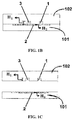
- Figure 1B shows a cross section of the separating device in which the transport channel (1) and collection channel (3) are machined in the upper part (102).
- the separating area can include an arrangement of micropillars (2) and is machined in the lower part (101).
- the height H2 is set according to the size of particles to be filtered, whereas height H1 of the channels 1 and 3 in the upper part (102) is set according to the thickness of the liquid required by the test to be performed.
- the capillary forces in the separating area 2 are greater than in the transport channel 1c having a smaller width such that the rate of flow of the sample in the main transport channel 1 is slowed down with respect to the rate of flow of the liquid that is extracted/filtered in the separating area 2, therefore the surface for entering the separating area 2 may be locked due to particle build-up.
- the main transport channel has a constriction (1b and 1d) to increase the rate of flow of the particles when they go below the separating area.
- Figure 2 illustrates the hydrodynamics principles used to prevent blockage at the inlet into the separating area.
- red blood cells tend to migrate into the vessels and leave the region adjacent to the vessel wall free of particles (known as plasma skimming.)
- plasma skimming the region adjacent to the vessel wall free of particles
- branching the reduced section of the transport channel used in the present invention and the symmetrical distribution of the separating area mean that it takes longer for particles to build up at the entry into the channel.
- Figure 3 illustrates another version of the microfluidic device in which the direction of the flow in the main channel 1a is parallel to the flow in the separating area 2 to increase the microdevice throughput.
- This has been achieved by construction of the transport channel with a curved shape.
- the blood plasma (extracted liquid) flows through the separating area faster than in the first version of the microdevice because the direction of flow is the same as in the separating area, but the filling time of the collection channel will increase because of the red blood cells blocking the inlet into the separating area due because the centrifugal force applied on these cells make them build up at the inlet into the separating area.
- Electrodes 4 and 5 can be used for applying alternating electrophoretic forces on the red blood cells to prevent blockage.
- Figure 4 illustrates a modified version of the microdevice mentioned in Figure 3 .
- the transport channel is also curved, but the collection channel is placed below the inlet and the outlet. Then the centrifugal force acting on the red blood cells/particles moves them away from the separating area.
- the extracted plasma or liquid flows through the separating area more slowly than in the version of the microdevice in Figure 3 because the direction of the flow of the liquid (or blood) is opposite the flow of the extracted liquid (or plasma.).
- Another hydrodynamic effect to delay blockage of the separating area is the increase in shear forces acting on the particles and therefore promoting flow by means of an increase in the capillary force by means of which the liquid is transported through the device.
- Figure 5 and Figure 6 show another version of the microfluidic device where the main channel 1e is extended through a set of parallel microchannels 41 in Figure 5 or through a set of circular micropillars 51 in Figure 6 .
- the particles are driven away from the inlet area of the separating area (2) by the induced shear force due to the generated capillary force of the these two micropumps (41 or 51).
- Figure 7 shows a design of a microdevice with three separation stages, including three separate areas 2, 21, 22 to increase the separation efficiency.
- the sample supplied in inlet port 11 flows through a primary main channel 1a which is connected to a main channel 1c having a smaller width through a curved constriction 1b.
- the sample introduced in the main channel 1 is diverted towards the area 2 and a secondary transport channel 15 which is designed to increase the induced shear force on the particles before reaching the next separating area 21.
- the three separating areas 2, 21, 22 are connected to a collection channel 3 which is used to collect the extracted liquid (or plasma).
- the separation occurs while the transport channel it is not completely filled, because once it is filled the rate of flow is so slow that the particles tend to block the inlet in the separating area.
- a final main channel 25 has been added to the end of the transport channel to increase the resistance to the flow and therefore the time it takes to completely fill it.
- the final main channel 25 is connected to an outlet port 12 where the concentrated liquid sample is collected.
- Figure 8 shows another three-stage design like the previous design ( Figure 7 ).
- the length of the main channel 1a is reduced to optimize the working time of the device, and the lengths of the transport channels 15 between separating areas are also reduced so that the separating time is faster and the amount of fluid that is extracted can therefore be maximized.
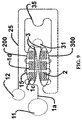
- Figure 9 shows a design with six stages of separation.
- the sample supplied in an inlet port 11 flows through a primary main channel 1a which is connected to a channel 1c having a smaller width through a curved constriction 1d.
- the sample introduced in the channel 1c having a smaller width is diverted towards the separating area 2 and a secondary transport channel 15, and after the separation of these three phases in the first separation part 200, the liquid sample is transmitted to the second separation part 300 by a transport channel 35.
- Two parallel collection channels 3 are designed for collecting the liquid extracted from each separation part and thus increasing the volume that is separated. In the case of separating plasma from blood, these two distinct channels make it possible to do two different blood analyses simultaneously in the same device.
Landscapes
- Health & Medical Sciences (AREA)
- Chemical & Material Sciences (AREA)
- Life Sciences & Earth Sciences (AREA)
- Engineering & Computer Science (AREA)
- Hematology (AREA)
- General Health & Medical Sciences (AREA)
- Analytical Chemistry (AREA)
- Physics & Mathematics (AREA)
- Biomedical Technology (AREA)
- Molecular Biology (AREA)
- Dispersion Chemistry (AREA)
- Chemical Kinetics & Catalysis (AREA)
- Clinical Laboratory Science (AREA)
- Biochemistry (AREA)
- Immunology (AREA)
- Pathology (AREA)
- General Physics & Mathematics (AREA)
- Biophysics (AREA)
- Food Science & Technology (AREA)
- Urology & Nephrology (AREA)
- Medicinal Chemistry (AREA)
- Ecology (AREA)
- Fluid Mechanics (AREA)
- Electrochemistry (AREA)
- Investigating Or Analysing Biological Materials (AREA)
- Sampling And Sample Adjustment (AREA)
- Automatic Analysis And Handling Materials Therefor (AREA)
- External Artificial Organs (AREA)
Abstract
Description
- The present invention relates to a microfluidic device separating particles from the liquid in which the particles are contained, maximizing the amount of liquid extracted from an initial mixture. More specifically, the present invention can separate plasma from a drop of blood to be part of a portable blood analysis device.
- Nowadays, considerable progress has been made in the field of microfluidics, especially for chemical, biological and biomedical applications. In fact, point-of-care testing products could not be developed were it not for this technology. Most attempts made by researchers in these years have been focused on developing a microfluidic chip for separating plasma from blood, but although many attempts have been made, there are still many challenges to be met, such as improving efficiency (the amount of plasma taken) without hemolysis (the rupture of red blood cells).
- The use of microfluidics not only increases convenience due to the small size, but also expedites test results.
- In traditional tests, blood samples sit for a great length of time before all the processes are completed. This increases the possibilities of errors and renders the blood to be in sub-optimal conditions.
- The new diagnostic tests can be more accurate, since the use of microfluidics allows using a drop of blood that has just been taken, so it is fresher, and since it is not manipulated errors are minimized and results are obtained faster.
- Blood is used in many analyses to detect a broad range of illnesses. Before that, however, the elements of blood are separated: plasma (serum and fibrinogen), red blood cells, white blood cells and platelets. Normal blood is made up of 45% red blood cells, 1% white blood cells, 0.5% platelets and the rest is plasma. Red blood cells are disk-shaped deformable cells with a diameter of 8 microns and a height of 2 microns. White blood cells have a diameter between 8 and 12 microns and prevent infections. Platelets are the other main blood component and they aggregate to form clots. All these particles are suspended in plasma, which consists of 90% plasma and is yellowish in color. Besides water, plasma contains small particles (between 1 and 3 microns in diameter) that are basically serum, albumin, clotting factors, hormones, carbon dioxide, proteins, electrolytes and immunoglobulin.
- Separating plasma from blood today is done by means of laboratory centrifugation and relatively large volumes (milliliters) of blood are required, or it is done by means of sedimentation but this process is very slow.
- In order to minimize errors, reduce the time between extraction and obtaining test results, "lab-on-a-chip" type devices are of interest for separating plasma from blood and subsequently performing the test. Researchers have developed plasma separation systems using different techniques in microfluidics, such as cross-flow filtration, deterministic lateral displacement, constricted flow, dielectrophoretic techniques or biomimetic separation, but most of these techniques require a pressure source or pump which users of a point-of-care test may not have available to them.
- There is another group of scientists who have focused on developing microfluidic filters without external sources, but the volume of plasma extracted before the inlet into the separating channel clogs is minimal and not enough to perform blood analyses.
- Accordingly, providing a device that could separate the maximum amount of liquid from a liquid containing deformable particles would be desirable.
-
Ralf-Peter Peters et al. U.S. Patent Application Publication No. US 2004/0232074 , disclose a microstructured separating device that separates plasma from blood. The microstructure includes a straight transport channel through which the blood circulates, a separating channel at a branch point of the transport channel which is adjoined thereto perpendicularly and having a different height. The plasma circulates in this branch point. This separating channel has a microstructure which retains the larger particles and slows down the smaller particles (chromatographic effect, i.e., the liquid transporting the particles tends to move faster than the particles do.). If the separating channel has a height exceeding the particles to be filtered or if the particles are deformable and can enter same, the quality of the filtered liquid is not 100% free of particles. However, if the filtration area has a height that is less than the particles to be filtered, there is no mechanism to prevent the inlet from clogging, such that the larger particles will close the inlet, limiting the amount of fluid that can be extracted. The high concentration of particles in blood (45% red blood cells) causes the separation due to the chromatographic effect to lead to a very limited plasma extraction, and most likely insufficient to implement blood tests. Furthermore, the design proposed in this patent is based on making channels having different heights in a single part and covering the channel with a cover, resulting in a complex manufacturing process. -
Jee-Hoon Seo et al., International Patent No. WO 2005/095954 , disclose another filter design that does not use membranes or other devices to separate plasma from blood. The filter consists of a substrate including a channel. Said channel has an inlet and at least two outlets separated from one another by a certain angle, and a set of rectangular structures (pillars) placed in the main channel at a certain angle with respect to one another. The rectangular structures in the channel allow separating plasma from blood according to the arrangement thereof. Although this invention provides a design for separating plasma from blood, the separation efficiency is not altogether good (a fair amount of particles are found in the outlet channel); due to the fact that the distance between pillars is about 10 microns and red blood cells can deform, the latter can get through the pillars near the outlet. - The goal of the present invention is to create a microfluidic chip that can be part of point-of-care testing devices that, with a single drop of blood, can separate a sufficient amount of plasma without the need of external forces to perform high-quality analyses (>90% without cells) and in a reasonable time (a matter of minutes).
- Another key aspect compared to previous patents is that the amount of volume extracted from the initial volume is maximized. This is achieved due to the fact that the present invention considers the rheological behavior of red blood cells in the transport channel and delays clogging of the inlet at least until the collection channel/chamber is filled. This delay is achieved acting on two points: first, the collection channel is filled faster than in earlier designs since the separating area is designed based on a high-efficiency capillary pump, in addition to having suitable hydrophilic behavior. Secondly, the concentration of red blood cells at the inlet to the separating area is minimized, which instead of being placed on one side of the transport channel as in patent No.
US 2004/0232074 , is placed symmetrically on both side of the transport channel. This compensates for the capillary forces acting on the red blood cells circulating in the transport channel, such that their path is not affected and the problem of clogging of the inlet into the separating area is reduced. Thirdly, if needed electrodes could be placed at the inlet and outlet of the channel to apply electrophoretic forces on the red blood cells, forcing them to move away from the inlet into the separating area. - Another goal of the present invention is to present a device that can be mass-produced using different manufacturing process. For this purpose the device has been split into two parts: the transport and separating channels are located in one part and the separating area in another. This feature, which is not disclosed in the other patents, could largely aid the production thereof.
- This invention consists of a
microfluidic device 100 for separating deformable particles from a liquid containing them without external forces by means of filtration outside the plane of the channel. The microfluidic device is made up of two parts: the top part (101) comprising at least one transport channel (1) using various hydrodynamics principles to maximize the volume of liquid separated by the device (100), and a bottom part (102) containing at least one separating area (2) filtering the particles and acting as a capillary pump in order to drive the fluid to the collection channel (3), which can be one or more in number and have a height that is adaptable depending on the sensitivity needs of the test to be implemented. - The separating area can include an array of pillars (which can have different shapes and can also be arranged depending on the amount of fluid to be extracted). If the amount of liquid extracted is not enough to perform the test, the device allows placing two electrodes (4 and 5) at the inlet and outlet in order to drive the red blood cells away from the inlet into the separating area and thereby allow an extraction of more fluid.
- The invention consists of a main channel (for transporting the liquid including the particles), which includes at least one constriction (1b), at which point or after which point the main channel is diverted and is connected to a filtration channel/area (2) located outside the plane of the transport channel. The particle-free fluid circulates through the channel (2). The constriction (1b) increases local speed of the particle and delays the inlet of the separating channel/area (2) from clogging, whereby increasing the amount of fluid that can be separated.
- In another design of the invention, the main channel (1) is extended after the separation by a capillary micropump which consists of a set of parallel channels (41) in
Figure 5 or an array of pillars (51) inFigure 6 . In these designs, the capillary forces promote greater flow in the channel such that the possibility of the inlet into the separating area being clogged is reduced. - The design of the invention has several advantages over earlier designs for separating particles from a liquid containing them, maximizing the amount of liquid that is extracted. On one hand, the design does not require external actuation, i.e., the capillary forces are enough to transport the liquid through the channels. The capillary force is achieved through the hydrophilicity of the material by either modifying hydrophobic materials such as PDMS (with hydrophilic coatings or O2 plasma treatments) or by directly using hydrophilic materials. If a hydrophobic material such as polydimethylsiloxane (PDMS) is used, nonionic surfactants can be applied to compensate for its hydrophobicity.
- This invention minimizes the concentration of red blood cells at the inlet into the separating area, so for this reason the height of the separating area (H2,
Figure 1b ) is less than the height of the main channel (H1,Figure 1b ), and clearly less than the diameter of the particles to be filtered. Therefore, the quality of the filtered liquid is better than in earlier designs, many of which had heights that were greater than the size of the particle to be filtered. Furthermore, when considering obtaining plasma from blood, the deformability of red blood cells makes it necessary to restrict the height H2 between 0.5 and 2 microns. - The design of the device can also have several separating areas located one after the other, e.g. see
Figures 7 ,8 and9 , where these areas are 21 and 22. - In order to collect the filtered plasma, the device has a collection channel (3) which collects the output of the different separating areas. In a point-of-care testing device, the reagents for performing the test could be located in this channel (3), or otherwise the filtered liquid could be collected with a syringe.
- The invention is described based on the following drawings.
-
Figure 1A shows an overall view of the microfluidic design claimed in the invention. -
Figure 1B shows a cross section of the design through the filtration area. -
Figure 2 is a schematic illustration of the increase in speed the particles are subjected to in the constriction in the main channel to avoid particles from building up in the filtration area. The progressive constriction for preventing damage to biological particles and the capillary forces applied to the particles as they go through the separating area are furthermore shown. -
Figure 3 shows a plan view of another version of the invention in which the main channel is curved. -
Figure 4 shows a plan view of another version of the invention in which the main channel is curved and the collection channel is located on the side opposite the plasma flow direction. -
Figure 5 shows a plan view of the invention to which a capillary pump (having parallel channels) has been added to promote flow in the main channel. -
Figure 6 shows a plan view of the invention to which a capillary pump (array of pillars) has been added to promote flow in the main channel. -
Figure 7 shows a plan view of the invention with three separating areas. -
Figure 8 shows a plan view of the invention with three separating areas with reduced length of the main channel after each separating area. -
Figure 9 shows a plan view of the invention with six separating areas to increase the amount of liquid that is extracted. -
Figure 1A illustrates a first version of the microfluidic device which has a straight transport channel (1) with an inlet port (11) and an outlet port (12), a primary main flow channel (1a) is linked through a constriction (1b) to a channel (1c) having a smaller width which later returns to being a channel (1e) having a normal width through another transition or constriction (1d). These two transitions (1b) and (1d) can be straight or curved, as shown inFigure 2 , to reduce the risk of damaging biological particles (cells). These two transitions provide a smooth reduction of the flow from 1a to 1c or 1c to 1e. Specifically in blood cells, hemolysis (the rupture of red blood cells) increases due to the induced stress in the constriction. - For most of its length, the transport channel (1c) having a smaller width is covered by a separating area (2) which is machined in another part (101). In the case of blood, the blood plasma which is to be separated flows through this separating area (2) which is also connected to a collection channel (3) where the blood analysis will be implemented. The filtered liquid is collected from the separating area by a collection channel (3) that is connected to the environment through an extraction port (31) or a test area. A syringe pump can be connected to the extraction port (31) in order to remove the separated blood plasma from the collection channel (3) if needed. If it were necessary to increase the extraction time, electrodes 4 and 5 can be placed to apply alternating electrical forces on the particles to prevent obstruction of the inlet into the separating area.
-
Figure 1B shows a cross section of the separating device in which the transport channel (1) and collection channel (3) are machined in the upper part (102). The separating area can include an arrangement of micropillars (2) and is machined in the lower part (101). The height H2 is set according to the size of particles to be filtered, whereas height H1 of thechannels - The capillary forces in the
separating area 2 are greater than in thetransport channel 1c having a smaller width such that the rate of flow of the sample in themain transport channel 1 is slowed down with respect to the rate of flow of the liquid that is extracted/filtered in theseparating area 2, therefore the surface for entering the separatingarea 2 may be locked due to particle build-up. To solve the blockage problem, the main transport channel has a constriction (1b and 1d) to increase the rate of flow of the particles when they go below the separating area.Figure 2 illustrates the hydrodynamics principles used to prevent blockage at the inlet into the separating area. Particularly when separating plasma from blood, red blood cells tend to migrate into the vessels and leave the region adjacent to the vessel wall free of particles (known as plasma skimming.) Furthermore, when a vessel branches into two, blood cells tend to move in the branch having the higher rate of flow and leave the branch having the lower rate of flow, which effect is known as branching. In addition to these two phenomena, the reduced section of the transport channel used in the present invention and the symmetrical distribution of the separating area mean that it takes longer for particles to build up at the entry into the channel. -
Figure 2 illustrates the fact that the extraction of plasma from blood is increased due to the use of a symmetrical filtration channel design ((d1=d2, seeFigure 2 ), which causes counteracting the cross capillary forces in the opposite direction, resulting in an unnoticeable force on the red blood cells circulating through the transport channel, and accordingly reduces blockage and increases extraction of plasma. -
Figure 3 illustrates another version of the microfluidic device in which the direction of the flow in themain channel 1a is parallel to the flow in theseparating area 2 to increase the microdevice throughput. This has been achieved by construction of the transport channel with a curved shape. The blood plasma (extracted liquid) flows through the separating area faster than in the first version of the microdevice because the direction of flow is the same as in the separating area, but the filling time of the collection channel will increase because of the red blood cells blocking the inlet into the separating area due because the centrifugal force applied on these cells make them build up at the inlet into the separating area. Electrodes 4 and 5 can be used for applying alternating electrophoretic forces on the red blood cells to prevent blockage. -
Figure 4 illustrates a modified version of the microdevice mentioned inFigure 3 . In this case, the transport channel is also curved, but the collection channel is placed below the inlet and the outlet. Then the centrifugal force acting on the red blood cells/particles moves them away from the separating area. The extracted plasma or liquid flows through the separating area more slowly than in the version of the microdevice inFigure 3 because the direction of the flow of the liquid (or blood) is opposite the flow of the extracted liquid (or plasma.). - Another hydrodynamic effect to delay blockage of the separating area is the increase in shear forces acting on the particles and therefore promoting flow by means of an increase in the capillary force by means of which the liquid is transported through the device.
-
Figure 5 andFigure 6 show another version of the microfluidic device where themain channel 1e is extended through a set ofparallel microchannels 41 inFigure 5 or through a set ofcircular micropillars 51 inFigure 6 . In both, the particles are driven away from the inlet area of the separating area (2) by the induced shear force due to the generated capillary force of the these two micropumps (41 or 51). -
Figure 7 shows a design of a microdevice with three separation stages, including threeseparate areas Figure 7 , the sample supplied ininlet port 11 flows through a primarymain channel 1a which is connected to amain channel 1c having a smaller width through acurved constriction 1b. The sample introduced in themain channel 1 is diverted towards thearea 2 and asecondary transport channel 15 which is designed to increase the induced shear force on the particles before reaching thenext separating area 21. The threeseparating areas collection channel 3 which is used to collect the extracted liquid (or plasma). The separation occurs while the transport channel it is not completely filled, because once it is filled the rate of flow is so slow that the particles tend to block the inlet in the separating area. InFigure 7 , a finalmain channel 25 has been added to the end of the transport channel to increase the resistance to the flow and therefore the time it takes to completely fill it. Finally, the finalmain channel 25 is connected to anoutlet port 12 where the concentrated liquid sample is collected. -
Figure 8 shows another three-stage design like the previous design (Figure 7 ). In this one, the length of themain channel 1a is reduced to optimize the working time of the device, and the lengths of thetransport channels 15 between separating areas are also reduced so that the separating time is faster and the amount of fluid that is extracted can therefore be maximized. -
Figure 9 shows a design with six stages of separation. In this design, the sample supplied in aninlet port 11 flows through a primarymain channel 1a which is connected to achannel 1c having a smaller width through acurved constriction 1d. The sample introduced in thechannel 1c having a smaller width is diverted towards the separatingarea 2 and asecondary transport channel 15, and after the separation of these three phases in thefirst separation part 200, the liquid sample is transmitted to thesecond separation part 300 by atransport channel 35. Twoparallel collection channels 3 are designed for collecting the liquid extracted from each separation part and thus increasing the volume that is separated. In the case of separating plasma from blood, these two distinct channels make it possible to do two different blood analyses simultaneously in the same device.
Claims (7)
- A self-driven (using no external forces) microfluidic device for separating particles from a liquid in which the particles are suspended and particularly for blood plasma separation, comprising the following:a) At least one transport channel (1) divided in three regions: 1a and 1e having a width w1 and 1c having a width w2, where w2 < w1. These three regions are connected through a constriction (which can be curved or not, see Figure 2) to transport the liquid from an inlet port (11) to an outlet port (12) and avoid clogging in the separating area due to the increased rate in the constriction.b) At least one separating area (2), which is completely or partially above the main transport channel (1c) having a smaller width, acting as a branch point to divert a desired partial flow of extracted liquid, which is symmetrically placed on both sides of the transport channel.c) At least one collection channel (3) that can include an outlet opening (31) or a reaction chamber.d) The microfluidic device (100) is machined in two parts. Part 101 contains the separating area or filter with a height (H2) less than the size of particles to be separated and 102 contains the transport channel and the collection channel and/or test chamber with the adaptable height according to the test/analysis to be performed.e) Both parts are manufactured using a suitable hydrophilic material or are treated to achieve a hydrophilic behavior in the hydrophobic material.
- The microfluidic device for separation of claim 1, wherein at least one micropump including parallel channels (41) or a collection of micropillars (51) is connected to the end of the main channel (1e) to promote flow.
- The microfluidic device of claims 1 and 2, wherein the transport channel 1 is curved as in Figure 3 and the separating area can be placed symmetrically.
- The microfluidic device of claims 1 and 2, wherein the transport channel 1 is curved as in Figure 3 and the separating area may not be symmetrical.
- The microfluidic device of claims 1 and 2, wherein the transport channel 1 is curved as in Figure 4 and the separating area can be placed symmetrically.
- The microfluidic device of claims 1 and 2, wherein the transport channel 1 is curved as in Figure 4 and the separating area may not be placed symmetrically.
- The microfluidic device of claims 1, 2, 3, 4, 5 and 6, wherein at least two electrodes 4 and 5 are placed at the inlet and outlet to apply alternating electrophoretic forces on the particles.
Applications Claiming Priority (2)
| Application Number | Priority Date | Filing Date | Title |
|---|---|---|---|
| ES201331666A ES2539843B2 (en) | 2013-11-15 | 2013-11-15 | Microfluidic device for the separation of liquid from the same liquid containing deformable particles without external energy sources |
| PCT/ES2014/070833 WO2015071515A1 (en) | 2013-11-15 | 2014-11-11 | Microfluidic device for separating liquid from the same liquid containing deformable particles without external sources of energy |
Publications (2)
| Publication Number | Publication Date |
|---|---|
| EP3070471A1 true EP3070471A1 (en) | 2016-09-21 |
| EP3070471A4 EP3070471A4 (en) | 2017-07-12 |
Family
ID=53056824
Family Applications (1)
| Application Number | Title | Priority Date | Filing Date |
|---|---|---|---|
| EP14861638.6A Withdrawn EP3070471A4 (en) | 2013-11-15 | 2014-11-11 | Microfluidic device for separating liquid from the same liquid containing deformable particles without external sources of energy |
Country Status (4)
| Country | Link |
|---|---|
| US (1) | US10041931B2 (en) |
| EP (1) | EP3070471A4 (en) |
| ES (1) | ES2539843B2 (en) |
| WO (1) | WO2015071515A1 (en) |
Families Citing this family (2)
| Publication number | Priority date | Publication date | Assignee | Title |
|---|---|---|---|---|
| ES2539843B2 (en) | 2013-11-15 | 2015-11-16 | Universitat Politècnica De Catalunya | Microfluidic device for the separation of liquid from the same liquid containing deformable particles without external energy sources |
| JP7003350B6 (en) * | 2015-12-11 | 2022-01-28 | パリ シアンス エ レットル | Biphasic gas / liquid plasma reactor |
Family Cites Families (9)
| Publication number | Priority date | Publication date | Assignee | Title |
|---|---|---|---|---|
| DE69619400T2 (en) * | 1995-06-16 | 2002-09-26 | Univ Washington Seattle | FLAT MICROPRODUCED CROSS-FLOW FILTER FOR LIQUIDS |
| WO2004084263A2 (en) * | 2002-09-07 | 2004-09-30 | Arizona Board Of Regents | Integrated apparatus and methods for treating liquids |
| DE10313201A1 (en) | 2003-03-21 | 2004-10-07 | Steag Microparts Gmbh | Microstructured separator and microfluidic process for separating liquid components from a liquid containing particles |
| KR20050096489A (en) | 2004-03-31 | 2005-10-06 | 주식회사 올메디쿠스 | Filter that can separate and transfer without special electricity or magnetic devices in substrate |
| GB0525997D0 (en) * | 2005-12-21 | 2006-02-01 | Oxford Biosensors Ltd | Micro-fluidic structures |
| MX346456B (en) * | 2008-02-27 | 2017-03-21 | Boehringer Ingelheim Microparts Gmbh | Apparatus for the separation of plasma. |
| WO2009140326A2 (en) * | 2008-05-16 | 2009-11-19 | Board Of Supervisors Of Louisiana State University And Agricultural And Mechanical College | Microfluidic isolation of tumor cells or other rare cells from whole blood or other liquids |
| US9201037B2 (en) * | 2011-03-14 | 2015-12-01 | Mark Schoenfisch | Microfluidic nitric oxide sensor |
| ES2539843B2 (en) | 2013-11-15 | 2015-11-16 | Universitat Politècnica De Catalunya | Microfluidic device for the separation of liquid from the same liquid containing deformable particles without external energy sources |
-
2013
- 2013-11-15 ES ES201331666A patent/ES2539843B2/en active Active
-
2014
- 2014-11-11 WO PCT/ES2014/070833 patent/WO2015071515A1/en not_active Ceased
- 2014-11-11 EP EP14861638.6A patent/EP3070471A4/en not_active Withdrawn
-
2016
- 2016-05-13 US US15/154,937 patent/US10041931B2/en not_active Expired - Fee Related
Also Published As
| Publication number | Publication date |
|---|---|
| ES2539843B2 (en) | 2015-11-16 |
| US10041931B2 (en) | 2018-08-07 |
| EP3070471A4 (en) | 2017-07-12 |
| ES2539843A1 (en) | 2015-07-06 |
| WO2015071515A1 (en) | 2015-05-21 |
| US20160258928A1 (en) | 2016-09-08 |
Similar Documents
| Publication | Publication Date | Title |
|---|---|---|
| US12427521B2 (en) | Sorting particles in a microfluidic device | |
| Sajeesh et al. | Particle separation and sorting in microfluidic devices: a review | |
| CN101498630B (en) | Sample pretreatment integrated chip | |
| EP3902630B1 (en) | Multi-dimensional double spiral device and methods of use thereof | |
| CN210510505U (en) | Siphon valve device, microfluidic structure and analysis device | |
| US10041931B2 (en) | Microfluidic device for separating liquid from the same liquid containing deformable particles without external sources of energy | |
| Geng et al. | Multi-component continuous separation chip composed of micropillar arrays in a split-level spiral channel | |
| CN100503422C (en) | microstructured cross-flow separation chip | |
| WO2022044600A1 (en) | Sample preparation device and sample preparation system | |
| US12629679B2 (en) | Spiral inertial microfluidic devices and methods to remove contaminants | |
| US20230347345A1 (en) | Spiral inertial microfluidic devices and methods to remove contaminants | |
| Chen et al. | Microfluidic Chips for Plasma Isolation from Whole Blood | |
| Chen et al. | Microdevice for continuous isolation of plasma from whole blood | |
| Wu et al. | Label-free blood cells separation and enrichment from whole blood by high-throughput hydrodynamic and inertial force | |
| Tervamäki | Label-free size-based rare cell separation by microfluidics | |
| Shah et al. | A novel passive microfluidic device for preprocessing whole blood for point of care diagnostics | |
| HK1243765B (en) | Combined sorting and concentrating particles in a microfluidic device | |
| Chen et al. | Design and fabrication of microfluidic chip with micro/nano structures | |
| HK1242781A1 (en) | Combined sorting and concentrating particles in a microfluidic device | |
| HK1242781B (en) | Combined sorting and concentrating particles in a microfluidic device |
Legal Events
| Date | Code | Title | Description |
|---|---|---|---|
| PUAI | Public reference made under article 153(3) epc to a published international application that has entered the european phase |
Free format text: ORIGINAL CODE: 0009012 |
|
| 17P | Request for examination filed |
Effective date: 20160610 |
|
| AK | Designated contracting states |
Kind code of ref document: A1 Designated state(s): AL AT BE BG CH CY CZ DE DK EE ES FI FR GB GR HR HU IE IS IT LI LT LU LV MC MK MT NL NO PL PT RO RS SE SI SK SM TR |
|
| AX | Request for extension of the european patent |
Extension state: BA ME |
|
| DAX | Request for extension of the european patent (deleted) | ||
| A4 | Supplementary search report drawn up and despatched |
Effective date: 20170614 |
|
| RIC1 | Information provided on ipc code assigned before grant |
Ipc: G01N 33/49 20060101AFI20170608BHEP Ipc: B01L 3/00 20060101ALI20170608BHEP |
|
| STAA | Information on the status of an ep patent application or granted ep patent |
Free format text: STATUS: EXAMINATION IS IN PROGRESS |
|
| 17Q | First examination report despatched |
Effective date: 20181127 |
|
| GRAP | Despatch of communication of intention to grant a patent |
Free format text: ORIGINAL CODE: EPIDOSNIGR1 |
|
| STAA | Information on the status of an ep patent application or granted ep patent |
Free format text: STATUS: GRANT OF PATENT IS INTENDED |
|
| INTG | Intention to grant announced |
Effective date: 20211208 |
|
| STAA | Information on the status of an ep patent application or granted ep patent |
Free format text: STATUS: THE APPLICATION IS DEEMED TO BE WITHDRAWN |
|
| 18D | Application deemed to be withdrawn |
Effective date: 20220420 |