EP3070458A1 - Fluorescence observation unit and fluorescence observation apparatus - Google Patents
Fluorescence observation unit and fluorescence observation apparatus Download PDFInfo
- Publication number
- EP3070458A1 EP3070458A1 EP16159376.9A EP16159376A EP3070458A1 EP 3070458 A1 EP3070458 A1 EP 3070458A1 EP 16159376 A EP16159376 A EP 16159376A EP 3070458 A1 EP3070458 A1 EP 3070458A1
- Authority
- EP
- European Patent Office
- Prior art keywords
- fluorescence
- fluorescence observation
- light
- pulsed laser
- laser light
- Prior art date
- Legal status (The legal status is an assumption and is not a legal conclusion. Google has not performed a legal analysis and makes no representation as to the accuracy of the status listed.)
- Granted
Links
- 230000003287 optical effect Effects 0.000 claims abstract description 103
- 210000001747 pupil Anatomy 0.000 claims abstract description 18
- 239000013307 optical fiber Substances 0.000 claims description 62
- 230000007246 mechanism Effects 0.000 claims description 17
- 230000008878 coupling Effects 0.000 claims description 11
- 238000010168 coupling process Methods 0.000 claims description 11
- 238000005859 coupling reaction Methods 0.000 claims description 11
- 239000000835 fiber Substances 0.000 claims description 11
- 238000003780 insertion Methods 0.000 claims description 10
- 230000037431 insertion Effects 0.000 claims description 10
- 201000009310 astigmatism Diseases 0.000 claims description 7
- 239000007788 liquid Substances 0.000 claims description 5
- 238000002073 fluorescence micrograph Methods 0.000 description 11
- 238000006243 chemical reaction Methods 0.000 description 7
- 230000000694 effects Effects 0.000 description 5
- 238000010586 diagram Methods 0.000 description 4
- 230000005284 excitation Effects 0.000 description 3
- 230000004048 modification Effects 0.000 description 3
- 238000012986 modification Methods 0.000 description 3
- 238000005452 bending Methods 0.000 description 2
- 230000008901 benefit Effects 0.000 description 2
- 238000001514 detection method Methods 0.000 description 2
- 230000001678 irradiating effect Effects 0.000 description 2
- 239000000126 substance Substances 0.000 description 2
- 241001465754 Metazoa Species 0.000 description 1
- 238000010171 animal model Methods 0.000 description 1
- 230000008859 change Effects 0.000 description 1
- 239000011521 glass Substances 0.000 description 1
- 239000000463 material Substances 0.000 description 1
- 230000000644 propagated effect Effects 0.000 description 1
- 230000004044 response Effects 0.000 description 1
- 230000035945 sensitivity Effects 0.000 description 1
- 238000002834 transmittance Methods 0.000 description 1
Images



Classifications
-
- G—PHYSICS
- G02—OPTICS
- G02B—OPTICAL ELEMENTS, SYSTEMS OR APPARATUS
- G02B21/00—Microscopes
- G02B21/0004—Microscopes specially adapted for specific applications
- G02B21/002—Scanning microscopes
- G02B21/0024—Confocal scanning microscopes (CSOMs) or confocal "macroscopes"; Accessories which are not restricted to use with CSOMs, e.g. sample holders
- G02B21/0052—Optical details of the image generation
- G02B21/0076—Optical details of the image generation arrangements using fluorescence or luminescence
-
- A—HUMAN NECESSITIES
- A61—MEDICAL OR VETERINARY SCIENCE; HYGIENE
- A61B—DIAGNOSIS; SURGERY; IDENTIFICATION
- A61B5/00—Measuring for diagnostic purposes; Identification of persons
- A61B5/0059—Measuring for diagnostic purposes; Identification of persons using light, e.g. diagnosis by transillumination, diascopy, fluorescence
-
- A—HUMAN NECESSITIES
- A61—MEDICAL OR VETERINARY SCIENCE; HYGIENE
- A61B—DIAGNOSIS; SURGERY; IDENTIFICATION
- A61B5/00—Measuring for diagnostic purposes; Identification of persons
- A61B5/0059—Measuring for diagnostic purposes; Identification of persons using light, e.g. diagnosis by transillumination, diascopy, fluorescence
- A61B5/0062—Arrangements for scanning
-
- G—PHYSICS
- G01—MEASURING; TESTING
- G01N—INVESTIGATING OR ANALYSING MATERIALS BY DETERMINING THEIR CHEMICAL OR PHYSICAL PROPERTIES
- G01N21/00—Investigating or analysing materials by the use of optical means, i.e. using sub-millimetre waves, infrared, visible or ultraviolet light
- G01N21/62—Systems in which the material investigated is excited whereby it emits light or causes a change in wavelength of the incident light
- G01N21/63—Systems in which the material investigated is excited whereby it emits light or causes a change in wavelength of the incident light optically excited
- G01N21/64—Fluorescence; Phosphorescence
- G01N21/6402—Atomic fluorescence; Laser induced fluorescence
-
- G—PHYSICS
- G01—MEASURING; TESTING
- G01N—INVESTIGATING OR ANALYSING MATERIALS BY DETERMINING THEIR CHEMICAL OR PHYSICAL PROPERTIES
- G01N21/00—Investigating or analysing materials by the use of optical means, i.e. using sub-millimetre waves, infrared, visible or ultraviolet light
- G01N21/62—Systems in which the material investigated is excited whereby it emits light or causes a change in wavelength of the incident light
- G01N21/63—Systems in which the material investigated is excited whereby it emits light or causes a change in wavelength of the incident light optically excited
- G01N21/64—Fluorescence; Phosphorescence
- G01N21/645—Specially adapted constructive features of fluorimeters
- G01N21/6456—Spatial resolved fluorescence measurements; Imaging
- G01N21/6458—Fluorescence microscopy
-
- G—PHYSICS
- G01—MEASURING; TESTING
- G01N—INVESTIGATING OR ANALYSING MATERIALS BY DETERMINING THEIR CHEMICAL OR PHYSICAL PROPERTIES
- G01N21/00—Investigating or analysing materials by the use of optical means, i.e. using sub-millimetre waves, infrared, visible or ultraviolet light
- G01N21/62—Systems in which the material investigated is excited whereby it emits light or causes a change in wavelength of the incident light
- G01N21/63—Systems in which the material investigated is excited whereby it emits light or causes a change in wavelength of the incident light optically excited
- G01N21/64—Fluorescence; Phosphorescence
- G01N21/6486—Measuring fluorescence of biological material, e.g. DNA, RNA, cells
-
- G—PHYSICS
- G02—OPTICS
- G02B—OPTICAL ELEMENTS, SYSTEMS OR APPARATUS
- G02B21/00—Microscopes
- G02B21/0004—Microscopes specially adapted for specific applications
- G02B21/002—Scanning microscopes
- G02B21/0024—Confocal scanning microscopes (CSOMs) or confocal "macroscopes"; Accessories which are not restricted to use with CSOMs, e.g. sample holders
- G02B21/0032—Optical details of illumination, e.g. light-sources, pinholes, beam splitters, slits, fibers
-
- G—PHYSICS
- G02—OPTICS
- G02B—OPTICAL ELEMENTS, SYSTEMS OR APPARATUS
- G02B21/00—Microscopes
- G02B21/0004—Microscopes specially adapted for specific applications
- G02B21/002—Scanning microscopes
- G02B21/0024—Confocal scanning microscopes (CSOMs) or confocal "macroscopes"; Accessories which are not restricted to use with CSOMs, e.g. sample holders
- G02B21/008—Details of detection or image processing, including general computer control
- G02B21/0084—Details of detection or image processing, including general computer control time-scale detection, e.g. strobed, ultra-fast, heterodyne detection
-
- G—PHYSICS
- G02—OPTICS
- G02B—OPTICAL ELEMENTS, SYSTEMS OR APPARATUS
- G02B21/00—Microscopes
- G02B21/36—Microscopes arranged for photographic purposes or projection purposes or digital imaging or video purposes including associated control and data processing arrangements
- G02B21/361—Optical details, e.g. image relay to the camera or image sensor
-
- G—PHYSICS
- G02—OPTICS
- G02B—OPTICAL ELEMENTS, SYSTEMS OR APPARATUS
- G02B27/00—Optical systems or apparatus not provided for by any of the groups G02B1/00 - G02B26/00, G02B30/00
- G02B27/0025—Optical systems or apparatus not provided for by any of the groups G02B1/00 - G02B26/00, G02B30/00 for optical correction, e.g. distorsion, aberration
-
- G—PHYSICS
- G02—OPTICS
- G02B—OPTICAL ELEMENTS, SYSTEMS OR APPARATUS
- G02B27/00—Optical systems or apparatus not provided for by any of the groups G02B1/00 - G02B26/00, G02B30/00
- G02B27/10—Beam splitting or combining systems
- G02B27/14—Beam splitting or combining systems operating by reflection only
- G02B27/141—Beam splitting or combining systems operating by reflection only using dichroic mirrors
Definitions
- the present invention relates to a fluorescence observation unit and a fluorescence observation apparatus.
- fluorescence generated at a light-focusing position due to a multiphoton excitation effect by focusing ultrashort pulsed laser light on a specimen is split off from the optical path of the ultrashort pulsed laser light immediately behind the objective lens, is guided to an external photodetector by an optical fiber, and is detected.
- a multiphoton-excitation-type observation apparatus like this, it is possible to focus the ultrashort pulsed laser light at a portion deep inside the sample, thus generating fluorescence, whereby it is possible to acquire a fluorescence image of the portion deep inside the sample.
- the fluorescence collected by the objective lens is split off immediately behind the objective lens, before returning to the scanner.
- the position of a fluorescence beam also varies accordingly.
- the scanning area scanned by the scanner is large, it is difficult to make the split-off fluorescence enter an optical fiber.
- the sample is a scattering material, such as a biological tissue
- the fluorescence generated at the light-focusing position of the ultrashort pulsed laser light is scattered by the sample in the course of returning to the objective lens.
- fluorescence collected from a wide area of the sample by using the objective lens is detected, a bright fluorescence image cannot be obtained.
- the present invention has been made in view of the above-described circumstances, and an object thereof is to provide a fluorescence observation unit and a fluorescence observation apparatus that can increase the scanning range of the ultrashort pulsed laser light and can acquire a bright fluorescence image by collecting, from a wider area of a sample, fluorescence generated by a multiphoton excitation effect.
- the present invention provides the following solutions.
- a first aspect of the present invention is a fluorescence observation unit including: a scanner that scans ultrashort pulsed laser light from a light source; a pupil projection lens that focuses the ultrashort pulsed laser light scanned by the scanner; an image-forming lens that converts the ultrashort pulsed laser light, focused by the pupil projection lens, to substantially collimated light and causes the ultrashort pulsed laser light to be incident on an objective lens; and a dichroic mirror that splits off, from the optical path of the ultrashort pulsed laser light, fluorescence that is generated at a light-focusing position as a result of the ultrashort pulsed laser light being focused on a sample by the objective lens and is collected by the objective lens.
- the image-forming lens includes a first optical system having positive refractive power and disposed adjacent to the objective lens, and a second optical system having negative refractive power and disposed at a position closer to the pupil projection lens than the first optical system is.
- the dichroic mirror is disposed between the first optical system and the second optical system.
- the ultrashort pulsed laser light from the light source is scanned by the scanner, is focused by the pupil projection lens, is converted into substantially collimated light by the image-forming lens, and is made incident on the objective lens.
- the ultrashort pulsed laser light entering the objective lens is focused on the sample disposed at the focal position of the objective lens, and the photon density is increased at this light-focusing position. As a result, a fluorescent substance existing in the sample is excited, and fluorescence is generated.
- the fluorescence generated at the focal position of the objective lens scatters in all directions in the sample, and only the fluorescence emitted from the surface of the sample in the direction in which the fluorescence enters the objective lens is collected by the objective lens. Thereafter, the fluorescence is converted to converging light by the first optical system, which has positive refractive power and constitutes the image-forming lens, and fluorescence entering the first optical system from outside the optical axis is also split off from the optical path of the ultrashort pulsed laser light by the dichroic mirror, in a state being refracted toward the optical axis direction.
- the fluorescence beam emitted from the focal position and collected by the objective lens fluctuates around the pupil position of the objective lens.
- the fluorescence by allowing the fluorescence to pass through the first optical system having positive refractive power, it is possible to reduce the amount of fluctuation.
- the fluorescence entering the objective lens from a relatively wide area around the focal position is also converted to converging light having a smaller diameter by passing through the first optical system having positive refractive power and is split off from the optical path of the ultrashort pulsed laser light by the dichroic mirror.
- the fluorescence observation unit may further include an astigmatism correcting plate between the first optical system and the second optical system.
- the light beam is shifted only in the inclination direction of the dichroic mirror due to the refraction occurring when the ultrashort pulsed laser light passes through the dichroic mirror disposed so as to be inclined in one direction with respect to the optical axis.
- an astigmatism correcting plate to shift the light beam in the direction opposite to the direction of the shift caused by the dichroic mirror, the shift of the light-focusing position of the ultrashort pulsed laser can be eliminated.
- a second aspect of the present invention is a fluorescence observation apparatus including: the fluorescence observation unit according to the first aspect; and a photodetector that detects the fluorescence split off by the dichroic mirror.
- the converging light formed by focusing the fluorescence fluctuating with a small amount of fluctuation and scattered in a wide area around the light-focusing position of the ultrashort pulsed laser light on the sample it is possible to acquire a bright and sharp fluorescence image at a deeper position in the sample.
- the fluorescence observation apparatus may further include an optical fiber that connects the fluorescence observation unit and the photodetector, and the fluorescence observation unit may include a coupling lens that focuses, at an end of the optical fiber, the fluorescence split off by the dichroic mirror.
- the fluorescence observation unit may include an optical-path deflecting member that deflects the fluorescence split off by the dichroic mirror in the direction parallel to the optical axis of the objective lens and causes the fluorescence to be incident on the coupling lens.
- the fluorescence observation apparatus may further include a relay lens that relays, to the photodetector, the fluorescence guided by the optical fiber and emitted from the other end of the optical fiber.
- the fluorescence entering one end of the optical fiber and guided by the optical fiber diverges at a predetermined divergence angle when emitted from the other end of the optical fiber, the fluorescence is converted to substantially collimated light by the relay lens, is focused again, and is made incident on the photodetector.
- the projection magnification of the relay lens from the other end of the optical fiber to a light-receiving surface of the photodetector is set such that the diameter of the fluorescence beam entering the photodetector is within the effective area of the light-receiving surface of the photodetector and such that the incident numerical aperture (incident NA) to the photodetector is within an allowable range of the photodetector.
- the relay lens may convert the fluorescence emitted from the other end of the optical fiber to a substantially collimated light beam
- the fluorescence observation apparatus may include a light-splitting dichroic mirror that splits the substantially collimated light beam, converted by the relay lens, according to the wavelength; and a plurality of the photodetectors that detect the fluorescences split by the light-splitting dichroic mirror, respectively.
- the fluorescence is split according to the wavelength by the light-splitting dichroic mirror disposed in the collimated light beam portion formed by the relay lens and is detected by different photodetectors.
- the fluorescence is split according to the wavelength by the light-splitting dichroic mirror disposed in the collimated light beam portion formed by the relay lens and is detected by different photodetectors.
- the fluorescence observation unit may include a housing in which the scanner, the pupil projection lens, the image-forming lens, and the dichroic mirror are mounted, and the photodetector may be fixed to the housing.
- the fluorescence observation unit may include an observation-light deflecting member that deflects the light from the sample, collected by the objective lens, in a direction different from the direction of the dichroic mirror; an image-acquisition element that acquires an image of the light deflected by the observation-light deflecting member; and an insertion/retraction mechanism that alternatively disposes the dichroic mirror and the observation-light deflecting member in the optical path of the ultrashort pulsed laser light.
- the observation-light deflecting member in the optical path of the ultrashort pulsed laser light between the first optical system and the second optical system, it is possible to deflect, with the observation-light deflecting member, the light from the sample collected by the objective lens and further focused by the first optical system in another direction and to acquire an image of the light with the image-acquisition element.
- the fluorescence observation apparatus may further include a swiveling mechanism that causes the fluorescence observation unit to swivel about an axis intersecting the optical axis of the objective lens near the focal position of the objective lens.
- the optical fiber may be a multi-mode fiber.
- the optical fiber may be a liquid fiber.
- the fluorescence observation apparatus may further include a light-source optical fiber that connects the light source for generating the ultrashort pulsed laser light and the fluorescence observation unit and guides the ultrashort pulsed laser light emitted from the light source to the fluorescence observation unit.
- the present invention provides an advantage that it is possible to increase the scanning range of ultrashort pulsed laser light and to acquire a bright fluorescence image by collecting, from a wider area of a sample, fluorescence generated by a multiphoton excitation effect.
- a fluorescence observation unit 3 and a fluorescence observation apparatus 1 according to an embodiment of the present invention will be described below with reference to the drawings.
- the fluorescence observation apparatus 1 is a multiphoton-excitation laser scanning microscope and includes a light source 2 that emits ultrashort pulsed laser light in a near-infrared band; a fluorescence observation unit 3, according to this embodiment, that irradiates a sample X with the ultrashort pulsed laser light emitted from the light source 2 and collects fluorescence generated in the sample X; a photomultiplier tube (photodetector) 4 that detects the fluorescence collected by the fluorescence observation unit 3; a first optical fiber (light-source optical fiber) 5 connecting the light source 2 and the fluorescence observation unit 3; a second optical fiber (optical fiber) 6 for guiding the fluorescence from the fluorescence observation unit 3 to the photomultiplier tube 4; a relay optical system (relay lens) 7; a swiveling mechanism 25 that can swivel the fluorescence observation unit 3; a controller 26 that inputs movement instructions to the light
- the fluorescence observation unit 3 includes a housing 8; and a scanner 9, a pupil projection lens 10, an image-forming lens 11, a dichroic mirror 12, a mirror (optical-path deflecting member) 13, and a coupling lens 14, which are accommodated in the housing 8.
- an objective lens 15 is replaceably mounted to the fluorescence observation unit 3.
- the scanner 9 is, for example, a so-called proximity galvanometer mirror, which includes two galvanometer mirrors 16 that are caused to swivel about non-parallel axes.
- the scanner 9 can two-dimensionally scan the ultrashort pulsed laser light emitted from the light source 2 and guided by the first optical fiber 5.
- the pupil projection lens 10 focuses the ultrashort pulsed laser light scanned by the scanner 9 to form an intermediate image.
- the image-forming lens 11 converts the ultrashort pulsed laser light, with which the pupil projection lens 10 has formed the intermediate image, into substantially collimated light and causes the light to enter the objective lens 15.
- the image-forming lens 11 includes a first optical system 17 having positive refractive power and a second optical system 18 having negative refractive power.
- the first optical system 17 is disposed adjacent to the base end of the objective lens 15.
- the second optical system 18 is disposed at a position closer to the pupil projection lens 10 than the first optical system 17 is, so as to be spaced from the first optical system 17 in the optical axis S direction.
- first optical system 17 and the second optical system 18 are each illustrated as being formed of a single lens, the configurations of the optical systems 17 and 18 are not limited thereto, and they may be each formed by combining a plurality of lenses so as to have positive refractive power or negative refractive power as a whole.
- the diverging ultrashort pulsed laser light entering the image-forming lens 11 from the pupil projection lens 10 diverges further as it passes through the second optical system 18, is focused and converted to substantially collimated light as it passes through the first optical system 17, and enters the objective lens 15.
- the dichroic mirror 12 is formed in the shape of a parallel flat plate and is disposed at an angle of, for example, 45° with respect to the optical axis S.
- the dichroic mirror 12 has such transmittance characteristics that it allows the ultrashort pulsed laser light to pass therethrough, while deflecting the fluorescence entering from the objective lens 15 by substantially 90° to split the fluorescence off from the optical path of the ultrashort pulsed laser light.
- the mirror 13 bends the optical path of the fluorescence such that the fluorescence split by the dichroic mirror 12 is further deflected by substantially 90° and is directed toward the opposite side of the objective lens 15, along the direction parallel to the optical axis S of the objective lens 15.
- the coupling lens 14 further focuses the fluorescence deflected by the mirror 13 and makes the fluorescence enter an incident end of the second optical fiber 6.
- the first optical fiber 5 is, for example, a single-mode fiber.
- the second optical fiber 6 is a multi-mode fiber, and, in particular, is preferably a liquid fiber.
- the core diameter, at the exit end, of the second optical fiber 6 is less than or equal to the effective diameter of the photomultiplier tube 4.
- the relay optical system 7 temporarily converts the diverging fluorescence, propagated by the second optical fiber 6 and emitted from the exit end, to substantially collimated light, focuses the fluorescence again, and causes it to be incident on a photoelectric conversion surface 19 of the photomultiplier tube 4.
- the projection magnification of the relay optical system 7 from the exit end of the second optical fiber 6 to the photoelectric conversion surface 19 of the photomultiplier tube 4 is set such that the diameter of the fluorescence beam entering the photomultiplier tube 4 is within the effective area of the photoelectric conversion surface 19 of the photomultiplier tube 4 and such that the incident NA to the photomultiplier tube 4 is within an allowable range of the photomultiplier tube 4.
- the preferred relay magnification of the relay optical system 7 is, for example, 1x.
- the swiveling mechanism 25 includes a slider (not shown) to which the housing 8 of the fluorescence observation unit 3 is fixed, and a circular arc shaped rail 28 for guiding the slider.
- the rail 28 has a circular arc shape centered on the focal position of the objective lens 15a or the vicinity thereof.
- the controller 26 includes a computer (not shown) that executes a control program for the light source 2 and the scanner 9 of the fluorescence observation unit 3, a memory (not shown) storing the control program executed by the computer, and an interface unit (not shown).
- the computer generates a two-dimensional image on the basis of the information about the position scanned by the scanner 9 according to the executed control program and the brightness signal detected by the photomultiplier tube 4.
- the memory stores the two-dimensional image generated by the computer.
- the interface unit includes a driver that transmits an operation instruction from the computer to the scanner 9 and a signal processing circuit that converts the signal detected by the photomultiplier tube 4 from analog to digital and transmits the signal to the computer.
- the monitor 27 displays the two-dimensional image generated by the computer.
- ultrashort pulsed laser light is generated by the light source 2, in response to the operation instruction from the controller 26.
- the ultrashort pulsed laser light generated by the light source 2 is guided to the fluorescence observation unit 3 via the first optical fiber 5.
- the ultrashort pulsed laser light entering the fluorescence observation unit 3 through the first optical fiber 5 is two-dimensionally scanned by the scanner 9 according to the operation instruction from the controller 26 transmitted via the driver, is focused by the pupil projection lens 10, is converted into substantially collimated light by the image-forming lens 11, and then enters the objective lens 15.
- the ultrashort pulsed laser light focused at the focal position of the objective lens 15 increases the photon density in a very limited area near the focal position and excites a fluorescent substance existing in that area to cause fluorescence to be generated.
- the generated fluorescence is radiated in all directions, as shown in FIG. 2 , and is scattered within the sample X. Of this scattered fluorescence, the fluorescence radiated from the surface of the sample X toward the objective lens 15 is collected by the objective lens 15.
- the fluorescence observation unit 3 because the image-forming lens 11 in which the first optical system 17 having positive refractive power and the second optical system 18 having negative refractive power are arranged at a distance from each other in the optical axis S direction is employed, an advantage is obtained that it is possible to reduce the rearside focal length and to make the image-forming lens 11 itself have a compact configuration, unlike the case of the typical microscope, where a convex-concave doublet lens is used as the image-forming lens 11.
- the fluorescence is split off by the dichroic mirror 12 that is disposed between the first optical system 17 and the second optical system 18, it is possible to split off the fluorescence that is focused with a strong refractive power, compared with a case where the fluorescence passing through the whole image-forming lens 11 is split off.
- the fluorescence generated at the focal position of the ultrashort pulsed laser light spreads around the focal position due to scattering inside the surrounding sample X. Because the spread fluorescence is also generated in the focal position of the ultrashort pulsed laser light, it is desirable to collect as much fluorescence as possible.
- the ultrashort pulsed laser light when the ultrashort pulsed laser light is focused at each position in the scanning range of the ultrashort pulsed laser light, scattered fluorescence enters the objective lens 15 from a wider area including the scanning range.
- the light entering the objective lens 15 from a wide area like this is collected by the objective lens 15 and then diverges toward the image-forming lens 11.
- the first optical system 17 disposed in the vicinity of the objective lens 15 has higher positive refractive power than a typical image-forming lens, the light enters a narrow area of the dichroic mirror 12, in the form of converging light the central axis of which coincides with the optical axis S of the objective lens 15.
- the dichroic mirror 12 is small, it is possible to split off the fluorescence coming from a wide area of the sample X from the optical path of the ultrashort pulsed laser light.
- the fluorescence split off by the dichroic mirror 12 is deflected by the mirror 13, is further focused by the coupling lens 14, and is made to enter the second optical fiber 6.
- the second optical fiber 6 is made of a multi-mode fiber, in particular, a liquid fiber, the core of the optical fiber 6 is large. Thus, it is possible to make the fluorescence focused by the coupling lens 14 efficiently enter the second optical fiber 6.
- the fluorescence observation unit 3 that causes the fluorescence coming from a wider area beyond the scanning range of the scanner 9 to be constantly incident on the second optical fiber 6, even when the ultrashort pulsed laser light is scanned by the scanner 9, the fluorescence entering the second optical fiber 6 does not fluctuate and can be made to efficiently enter the second optical fiber 6.
- the fluorescence guided by the second optical fiber 6 is emitted from the exit end of the second optical fiber 6, is relayed by the relay optical system 7, and is incident on the photoelectric conversion surface 19 of the photomultiplier tube 4, where it is detected as a brightness signal.
- the detected brightness signal is converted from analog to digital by the signal processing circuit and is transmitted to the computer.
- the computer generates a two-dimensional image on the basis of the transmitted brightness signal and the information about the position scanned by the scanner 9, and the generated two-dimensional image is stored in the memory. As a result, it is possible to display the two-dimensional image stored in the memory on the monitor 27 as necessary and to observe the fluorescence of the sample X.
- the relay magnification of the relay optical system 7 is set such that the core diameter, at the exit end, of the second optical fiber 6 is projected within the effective area of the photoelectric conversion surface 19.
- the relay magnification of the relay optical system 7 as viewed from the photomultiplier tube 4 side to substantially 1x or less, the inclination of the fluorescence entering the photoelectric conversion surface 19 is reduced, which is advantageous for preventing a decrease in intensity of detected light due to the angular dependence of the detection sensitivity.
- the core diameter, at the exit end, of the second optical fiber 6 is less than or equal to the effective diameter of the photomultiplier tube 4, all of the fluorescence guided by the second optical fiber 6 is incident on the photoelectric conversion surface 19 of the photomultiplier tube 4. Thus, it is possible to efficiently detect the fluorescence, without being influenced by the entrance position dependence.
- the fluorescence deflected by 90° by the dichroic mirror 12 is further deflected by 90° by the mirror 13, it is possible to easily make the fluorescence, focused by the coupling lens 14, enter the second optical fiber 6 fixed to the housing 8 so as to extend in the direction substantially parallel to the optical axis S of the objective lens 15.
- the second optical fiber 6 does not inhibit such a movement, and it is possible to make the space around the objective lens 15 more compact, ensuring a large swiveling angle.
- dichroic mirrors (light-splitting dichroic mirrors) 20 may be disposed in the optical path of the collimated light formed by the relay optical system 7 to split the fluorescence according to the wavelengths and to detect the split-off fluorescences with separate photomultiplier tubes 4a, 4b, and 4c.
- the dichroic mirror 12 formed of a parallel flat plate, is disposed between the first optical system 17 and the second optical system 18, the ultrashort pulsed laser light passing through the dichroic mirror 12 is refracted as it passes through the dichroic mirror 12 and is shifted (astigmatism) in the direction in which the dichroic mirror 12 is inclined.
- an astigmatism correcting plate 21 which is formed of a glass parallel flat plate having the same thickness as the dichroic mirror 12 and inclined by the same angle as the dichroic mirror 12 but in the opposite direction, may be provided. By doing so, it is possible to prevent a shift in focal position of the ultrashort pulsed laser light due to the dichroic mirror 12.
- a mirror (observation-light deflecting member) 22 inclined in a direction different from the direction in which the dichroic mirror 12 is inclined may be provided, and an insertion/retraction mechanism (not shown) that moves the dichroic mirror 12 and the mirror 22 in a direction as indicated by an arrow Y to alternatively dispose the mirrors 12 and 22 on the optical axis S of the objective lens 15 may be provided.
- the insertion/retraction mechanism is, for example, a linear motion mechanism.
- the fluorescence observation unit 3 includes an image-acquisition element 23 that captures an image of the light reflected by the mirror 22.
- reference sign 24 denotes a mirror.
- the image-acquisition element 23 is connected to the controller 26.
- the memory stores a camera-observation image acquired by the image-acquisition element 23.
- the mirror 22 is disposed on the optical axis S of the objective lens 15 by actuating the insertion/retraction mechanism, by stopping the irradiation with the ultrashort pulsed laser light and by irradiating the sample X with white light from outside the fluorescence observation unit 3, the reflected light from the sample X collected by the objective lens 15 is reflected by the mirrors 22 and 24, and an image of the reflected light is captured by the image-acquisition element 23. In this way, it is possible to acquire the camera-observation image of the surface of the sample X.
- the photomultiplier tube 4 may be fixed to the housing 8, and the fluorescence may be detected by the photomultiplier tube 4, without passing through the optical fiber 6.
- the reflected light from the surface of the sample X, deflected by the mirror 22 is deflected by the mirror 24, instead, an image of the reflected light may be directly captured by the image-acquisition element 23 after the reflected light is deflected by the mirror 22.
Landscapes
- Health & Medical Sciences (AREA)
- Physics & Mathematics (AREA)
- Life Sciences & Earth Sciences (AREA)
- General Physics & Mathematics (AREA)
- Analytical Chemistry (AREA)
- Chemical & Material Sciences (AREA)
- General Health & Medical Sciences (AREA)
- Pathology (AREA)
- Optics & Photonics (AREA)
- Engineering & Computer Science (AREA)
- Nuclear Medicine, Radiotherapy & Molecular Imaging (AREA)
- Biochemistry (AREA)
- Immunology (AREA)
- Biomedical Technology (AREA)
- Molecular Biology (AREA)
- Surgery (AREA)
- Biophysics (AREA)
- Heart & Thoracic Surgery (AREA)
- Medical Informatics (AREA)
- Animal Behavior & Ethology (AREA)
- Public Health (AREA)
- Veterinary Medicine (AREA)
- Radiology & Medical Imaging (AREA)
- General Engineering & Computer Science (AREA)
- Computer Vision & Pattern Recognition (AREA)
- Multimedia (AREA)
- Microscoopes, Condenser (AREA)
- Investigating, Analyzing Materials By Fluorescence Or Luminescence (AREA)
Abstract
Description
- The present invention relates to a fluorescence observation unit and a fluorescence observation apparatus.
- In the related art, there is a known observation apparatus for observing a living sample, such as a small laboratory animal, with which observation is performed by disposing an objective lens in various directions or at various positions with respect to the sample (for example, see PTL 1).
- In this observation apparatus disclosed in
PTL 1, fluorescence generated at a light-focusing position due to a multiphoton excitation effect by focusing ultrashort pulsed laser light on a specimen is split off from the optical path of the ultrashort pulsed laser light immediately behind the objective lens, is guided to an external photodetector by an optical fiber, and is detected. By using a multiphoton-excitation-type observation apparatus like this, it is possible to focus the ultrashort pulsed laser light at a portion deep inside the sample, thus generating fluorescence, whereby it is possible to acquire a fluorescence image of the portion deep inside the sample. - {PTL 1}
Japanese Unexamined Patent Application, Publication No. 2005-300655 - However, in the case of the multiphoton-excitation-type observation apparatus, the fluorescence collected by the objective lens is split off immediately behind the objective lens, before returning to the scanner. Hence, when ultrashort pulsed laser light is scanned over the sample by the scanner, the position of a fluorescence beam also varies accordingly. Hence, in the case in which the scanning area scanned by the scanner is large, it is difficult to make the split-off fluorescence enter an optical fiber.
- Furthermore, when the sample is a scattering material, such as a biological tissue, the fluorescence generated at the light-focusing position of the ultrashort pulsed laser light is scattered by the sample in the course of returning to the objective lens. Thus, there is an inconvenience that, unless fluorescence collected from a wide area of the sample by using the objective lens is detected, a bright fluorescence image cannot be obtained.
- The present invention has been made in view of the above-described circumstances, and an object thereof is to provide a fluorescence observation unit and a fluorescence observation apparatus that can increase the scanning range of the ultrashort pulsed laser light and can acquire a bright fluorescence image by collecting, from a wider area of a sample, fluorescence generated by a multiphoton excitation effect.
- To achieve the above-described object, the present invention provides the following solutions.
- A first aspect of the present invention is a fluorescence observation unit including: a scanner that scans ultrashort pulsed laser light from a light source; a pupil projection lens that focuses the ultrashort pulsed laser light scanned by the scanner; an image-forming lens that converts the ultrashort pulsed laser light, focused by the pupil projection lens, to substantially collimated light and causes the ultrashort pulsed laser light to be incident on an objective lens; and a dichroic mirror that splits off, from the optical path of the ultrashort pulsed laser light, fluorescence that is generated at a light-focusing position as a result of the ultrashort pulsed laser light being focused on a sample by the objective lens and is collected by the objective lens. The image-forming lens includes a first optical system having positive refractive power and disposed adjacent to the objective lens, and a second optical system having negative refractive power and disposed at a position closer to the pupil projection lens than the first optical system is. The dichroic mirror is disposed between the first optical system and the second optical system.
- According to the first aspect of the present invention, the ultrashort pulsed laser light from the light source is scanned by the scanner, is focused by the pupil projection lens, is converted into substantially collimated light by the image-forming lens, and is made incident on the objective lens. The ultrashort pulsed laser light entering the objective lens is focused on the sample disposed at the focal position of the objective lens, and the photon density is increased at this light-focusing position. As a result, a fluorescent substance existing in the sample is excited, and fluorescence is generated.
- The fluorescence generated at the focal position of the objective lens scatters in all directions in the sample, and only the fluorescence emitted from the surface of the sample in the direction in which the fluorescence enters the objective lens is collected by the objective lens. Thereafter, the fluorescence is converted to converging light by the first optical system, which has positive refractive power and constitutes the image-forming lens, and fluorescence entering the first optical system from outside the optical axis is also split off from the optical path of the ultrashort pulsed laser light by the dichroic mirror, in a state being refracted toward the optical axis direction.
- Specifically, when the light-focusing position of the ultrashort pulsed laser light on the sample is moved by the scanner, the fluorescence beam emitted from the focal position and collected by the objective lens fluctuates around the pupil position of the objective lens. However, by allowing the fluorescence to pass through the first optical system having positive refractive power, it is possible to reduce the amount of fluctuation.
- Furthermore, the fluorescence entering the objective lens from a relatively wide area around the focal position is also converted to converging light having a smaller diameter by passing through the first optical system having positive refractive power and is split off from the optical path of the ultrashort pulsed laser light by the dichroic mirror.
- Hence, it is possible to split off, with the dichroic mirror, the fluorescence that cannot be split off in the form of a collimated light beam emitted from the objective lens and to efficiently detect the fluorescence. Thus, even when the ultrashort pulsed laser light is focused at a deeper position in the sample, a bright and sharp fluorescence image can be acquired.
- According to the first aspect of the present invention, the fluorescence observation unit may further include an astigmatism correcting plate between the first optical system and the second optical system.
- Because the fluorescence between the first optical system and the second optical system is converging light due to the first optical system having positive refractive power, the light beam is shifted only in the inclination direction of the dichroic mirror due to the refraction occurring when the ultrashort pulsed laser light passes through the dichroic mirror disposed so as to be inclined in one direction with respect to the optical axis. By disposing an astigmatism correcting plate to shift the light beam in the direction opposite to the direction of the shift caused by the dichroic mirror, the shift of the light-focusing position of the ultrashort pulsed laser can be eliminated.
- A second aspect of the present invention is a fluorescence observation apparatus including: the fluorescence observation unit according to the first aspect; and a photodetector that detects the fluorescence split off by the dichroic mirror.
- According to the second aspect of the present invention, by detecting, with the photodetector, the converging light formed by focusing the fluorescence fluctuating with a small amount of fluctuation and scattered in a wide area around the light-focusing position of the ultrashort pulsed laser light on the sample, it is possible to acquire a bright and sharp fluorescence image at a deeper position in the sample.
- In the second aspect of the present invention, the fluorescence observation apparatus may further include an optical fiber that connects the fluorescence observation unit and the photodetector, and the fluorescence observation unit may include a coupling lens that focuses, at an end of the optical fiber, the fluorescence split off by the dichroic mirror.
- With this configuration, by fixing the photodetector somewhere outside the fluorescence observation unit and by bending the optical fiber, it is possible to move the fluorescence observation unit. Hence, it is possible to move the fluorescence observation unit while fixing the sample and to observe the various portions of the sample from various directions.
- In the second aspect of the present invention, the fluorescence observation unit may include an optical-path deflecting member that deflects the fluorescence split off by the dichroic mirror in the direction parallel to the optical axis of the objective lens and causes the fluorescence to be incident on the coupling lens.
- With this configuration, it is possible to deflect the optical path of the fluorescence, focused by the coupling lens, with the optical-path deflecting member and to cause the fluorescence to be incident on the optical fiber disposed in the direction parallel to the optical axis of the objective lens. In other words, it is possible to extend the optical fiber from the fluorescence observation unit in the direction parallel to the optical axis of the objective lens. As a result, even when the fluorescence observation unit is swiveled about the axis intersecting the optical axis near the focal position of the objective lens, the optical fiber does not inhibit such a movement, and it is possible to make the space around the objective lens compact and to ensure a large swiveling angle.
- In the second aspect of the present invention, the fluorescence observation apparatus may further include a relay lens that relays, to the photodetector, the fluorescence guided by the optical fiber and emitted from the other end of the optical fiber.
- With this configuration, although the fluorescence entering one end of the optical fiber and guided by the optical fiber diverges at a predetermined divergence angle when emitted from the other end of the optical fiber, the fluorescence is converted to substantially collimated light by the relay lens, is focused again, and is made incident on the photodetector. The projection magnification of the relay lens from the other end of the optical fiber to a light-receiving surface of the photodetector is set such that the diameter of the fluorescence beam entering the photodetector is within the effective area of the light-receiving surface of the photodetector and such that the incident numerical aperture (incident NA) to the photodetector is within an allowable range of the photodetector. Thus, it is possible to efficiently detect the fluorescence, without being influenced by the dependence of the photodetector on the angle and the entrance position.
- In the second aspect of the present invention, the relay lens may convert the fluorescence emitted from the other end of the optical fiber to a substantially collimated light beam, and the fluorescence observation apparatus may include a light-splitting dichroic mirror that splits the substantially collimated light beam, converted by the relay lens, according to the wavelength; and a plurality of the photodetectors that detect the fluorescences split by the light-splitting dichroic mirror, respectively.
- With this configuration, the fluorescence is split according to the wavelength by the light-splitting dichroic mirror disposed in the collimated light beam portion formed by the relay lens and is detected by different photodetectors. Thus, it is possible to acquire a bright and sharp fluorescence image with each wavelength.
- In the second aspect of the present invention, the fluorescence observation unit may include a housing in which the scanner, the pupil projection lens, the image-forming lens, and the dichroic mirror are mounted, and the photodetector may be fixed to the housing.
- With this configuration, it is possible to detect the fluorescence split off by the dichroic mirror with the photodetector directly or via a few optical elements, without using the optical fiber. Thus, it is possible to reduce the loss of the fluorescence occurring every time the fluorescence passes through an optical element and to acquire a brighter fluorescence image.
- In the second aspect of the present invention, the fluorescence observation unit may include an observation-light deflecting member that deflects the light from the sample, collected by the objective lens, in a direction different from the direction of the dichroic mirror; an image-acquisition element that acquires an image of the light deflected by the observation-light deflecting member; and an insertion/retraction mechanism that alternatively disposes the dichroic mirror and the observation-light deflecting member in the optical path of the ultrashort pulsed laser light.
- With this configuration, by actuating the insertion/retraction mechanism and disposing the dichroic mirror in the optical path of the ultrashort pulsed laser light between the first optical system and the second optical system, it is possible to split off, with the dichroic mirror, the fluorescence collected by the objective lens and further focused by the first optical system from the optical path of the ultrashort pulsed laser light and to detect the fluorescence with the photodetector. On the other hand, by actuating the insertion/retraction mechanism and disposing the observation-light deflecting member in the optical path of the ultrashort pulsed laser light between the first optical system and the second optical system, it is possible to deflect, with the observation-light deflecting member, the light from the sample collected by the objective lens and further focused by the first optical system in another direction and to acquire an image of the light with the image-acquisition element. Thus, for example, it is possible to acquire an image of the surface of the sample to confirm the observation position and then switch to the dichroic mirror to observe the fluorescence image.
- In the second aspect of the present invention, the fluorescence observation apparatus may further include a swiveling mechanism that causes the fluorescence observation unit to swivel about an axis intersecting the optical axis of the objective lens near the focal position of the objective lens.
- With this configuration, by actuating the swiveling mechanism, it is possible to change the direction of the optical axis of the objective lens while substantially fixing the focal position of the objective lens on the sample and to observe the sample from various directions, while fixing the sample.
- In the second aspect of the present invention, the optical fiber may be a multi-mode fiber.
- In the second aspect of the present invention, the optical fiber may be a liquid fiber.
- With this configuration, by using the multi-mode fiber having a large core, in particular, by using the liquid fiber, it is possible to reduce the loss of the fluorescence fluctuating with a small amount of fluctuation, the loss occurring when entering the optical fiber, and to cause the fluorescence to be efficiently incident on the photodetector.
- In the second aspect of the present invention, the fluorescence observation apparatus may further include a light-source optical fiber that connects the light source for generating the ultrashort pulsed laser light and the fluorescence observation unit and guides the ultrashort pulsed laser light emitted from the light source to the fluorescence observation unit.
- With this configuration, by also fixing the light source for generating the ultrashort pulsed laser light somewhere outside the fluorescence observation unit and by bending the light-source optical fiber, it is possible to easily move the fluorescence observation unit and to observe the sample from various positions, while fixing the sample.
- The present invention provides an advantage that it is possible to increase the scanning range of ultrashort pulsed laser light and to acquire a bright fluorescence image by collecting, from a wider area of a sample, fluorescence generated by a multiphoton excitation effect.
-
- {
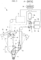
FIG. 1} FIG. 1 illustrates a schematic diagram of the overall configuration of a fluorescence observation apparatus according to an embodiment of the present invention. - {
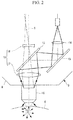
FIG. 2} FIG. 2 illustrates a partial enlarged view ofFig. 1 for explaining detection of fluorescence by a fluorescence observation unit provided in the fluorescence observation apparatus inFIG. 1 . - {
FIG. 3} FIG. 3 illustrates a schematic diagram of the overall configuration of a first modification of the fluorescence observation apparatus inFIG. 1 for detecting multiple-wavelength fluorescence. - {
FIG. 4} FIG. 4 illustrates a second modification of the fluorescence observation apparatus inFIG. 1 , and illustrates a diagram for explaining the effect of an astigmatism correcting plate. - {
FIG. 5} FIG. 5 illustrates a schematic diagram of the overall configuration of a third modification of the fluorescence observation apparatus inFIG. 1 having a mechanism for observing the surface of a sample. - {
FIG. 6} FIG. 6 illustrates a perspective view for explaining an insertion/retraction operation of a dichroic mirror and a mirror provided in the fluorescence observation apparatus inFig. 5 . - A
fluorescence observation unit 3 and afluorescence observation apparatus 1 according to an embodiment of the present invention will be described below with reference to the drawings. - As shown in
FIG. 1 , thefluorescence observation apparatus 1 according to this embodiment is a multiphoton-excitation laser scanning microscope and includes alight source 2 that emits ultrashort pulsed laser light in a near-infrared band; afluorescence observation unit 3, according to this embodiment, that irradiates a sample X with the ultrashort pulsed laser light emitted from thelight source 2 and collects fluorescence generated in the sample X; a photomultiplier tube (photodetector) 4 that detects the fluorescence collected by thefluorescence observation unit 3; a first optical fiber (light-source optical fiber) 5 connecting thelight source 2 and thefluorescence observation unit 3; a second optical fiber (optical fiber) 6 for guiding the fluorescence from thefluorescence observation unit 3 to thephotomultiplier tube 4; a relay optical system (relay lens) 7; a swivelingmechanism 25 that can swivel thefluorescence observation unit 3; acontroller 26 that inputs movement instructions to thelight source 2 and thefluorescence observation unit 3; and amonitor 27. - The
fluorescence observation unit 3 includes ahousing 8; and ascanner 9, apupil projection lens 10, an image-forminglens 11, adichroic mirror 12, a mirror (optical-path deflecting member) 13, and acoupling lens 14, which are accommodated in thehousing 8. - Furthermore, an
objective lens 15 is replaceably mounted to thefluorescence observation unit 3. - The
scanner 9 is, for example, a so-called proximity galvanometer mirror, which includes two galvanometer mirrors 16 that are caused to swivel about non-parallel axes. Thescanner 9 can two-dimensionally scan the ultrashort pulsed laser light emitted from thelight source 2 and guided by the firstoptical fiber 5. - The
pupil projection lens 10 focuses the ultrashort pulsed laser light scanned by thescanner 9 to form an intermediate image. - The image-forming
lens 11 converts the ultrashort pulsed laser light, with which thepupil projection lens 10 has formed the intermediate image, into substantially collimated light and causes the light to enter theobjective lens 15. - In this embodiment, the image-forming
lens 11 includes a firstoptical system 17 having positive refractive power and a secondoptical system 18 having negative refractive power. The firstoptical system 17 is disposed adjacent to the base end of theobjective lens 15. The secondoptical system 18 is disposed at a position closer to thepupil projection lens 10 than the firstoptical system 17 is, so as to be spaced from the firstoptical system 17 in the optical axis S direction. - In the drawings, although the first
optical system 17 and the secondoptical system 18 are each illustrated as being formed of a single lens, the configurations of theoptical systems - Specifically, the diverging ultrashort pulsed laser light entering the image-forming
lens 11 from thepupil projection lens 10 diverges further as it passes through the secondoptical system 18, is focused and converted to substantially collimated light as it passes through the firstoptical system 17, and enters theobjective lens 15. - The
dichroic mirror 12 is formed in the shape of a parallel flat plate and is disposed at an angle of, for example, 45° with respect to the optical axis S. Thedichroic mirror 12 has such transmittance characteristics that it allows the ultrashort pulsed laser light to pass therethrough, while deflecting the fluorescence entering from theobjective lens 15 by substantially 90° to split the fluorescence off from the optical path of the ultrashort pulsed laser light. - The
mirror 13 bends the optical path of the fluorescence such that the fluorescence split by thedichroic mirror 12 is further deflected by substantially 90° and is directed toward the opposite side of theobjective lens 15, along the direction parallel to the optical axis S of theobjective lens 15. - The
coupling lens 14 further focuses the fluorescence deflected by themirror 13 and makes the fluorescence enter an incident end of the secondoptical fiber 6. - The first
optical fiber 5 is, for example, a single-mode fiber. - The second
optical fiber 6 is a multi-mode fiber, and, in particular, is preferably a liquid fiber. The core diameter, at the exit end, of the secondoptical fiber 6 is less than or equal to the effective diameter of thephotomultiplier tube 4. - The relay
optical system 7 temporarily converts the diverging fluorescence, propagated by the secondoptical fiber 6 and emitted from the exit end, to substantially collimated light, focuses the fluorescence again, and causes it to be incident on aphotoelectric conversion surface 19 of thephotomultiplier tube 4. The projection magnification of the relayoptical system 7 from the exit end of the secondoptical fiber 6 to thephotoelectric conversion surface 19 of thephotomultiplier tube 4 is set such that the diameter of the fluorescence beam entering thephotomultiplier tube 4 is within the effective area of thephotoelectric conversion surface 19 of thephotomultiplier tube 4 and such that the incident NA to thephotomultiplier tube 4 is within an allowable range of thephotomultiplier tube 4. The preferred relay magnification of the relayoptical system 7 is, for example, 1x. - The swiveling
mechanism 25 includes a slider (not shown) to which thehousing 8 of thefluorescence observation unit 3 is fixed, and a circular arc shapedrail 28 for guiding the slider. Therail 28 has a circular arc shape centered on the focal position of the objective lens 15a or the vicinity thereof. By moving the slider over therail 28, thefluorescence observation unit 3 can be swiveled about the axis located at the focal position of theobjective lens 15 or the vicinity thereof. - The
controller 26 includes a computer (not shown) that executes a control program for thelight source 2 and thescanner 9 of thefluorescence observation unit 3, a memory (not shown) storing the control program executed by the computer, and an interface unit (not shown). The computer generates a two-dimensional image on the basis of the information about the position scanned by thescanner 9 according to the executed control program and the brightness signal detected by thephotomultiplier tube 4. The memory stores the two-dimensional image generated by the computer. - The interface unit includes a driver that transmits an operation instruction from the computer to the
scanner 9 and a signal processing circuit that converts the signal detected by thephotomultiplier tube 4 from analog to digital and transmits the signal to the computer. - The
monitor 27 displays the two-dimensional image generated by the computer. - The operation of the
fluorescence observation unit 3 andfluorescence observation apparatus 1 according to this embodiment, configured as above, will be described below. - When a fluorescence image of a relatively deep portion in the sample X is to be acquired using the
fluorescence observation apparatus 1 according to this embodiment, ultrashort pulsed laser light is generated by thelight source 2, in response to the operation instruction from thecontroller 26. The ultrashort pulsed laser light generated by thelight source 2 is guided to thefluorescence observation unit 3 via the firstoptical fiber 5. - The ultrashort pulsed laser light entering the
fluorescence observation unit 3 through the firstoptical fiber 5 is two-dimensionally scanned by thescanner 9 according to the operation instruction from thecontroller 26 transmitted via the driver, is focused by thepupil projection lens 10, is converted into substantially collimated light by the image-forminglens 11, and then enters theobjective lens 15. The ultrashort pulsed laser light focused at the focal position of theobjective lens 15 increases the photon density in a very limited area near the focal position and excites a fluorescent substance existing in that area to cause fluorescence to be generated. - The generated fluorescence is radiated in all directions, as shown in
FIG. 2 , and is scattered within the sample X. Of this scattered fluorescence, the fluorescence radiated from the surface of the sample X toward theobjective lens 15 is collected by theobjective lens 15. - In this case, with the
fluorescence observation unit 3 according to this embodiment, because the image-forminglens 11 in which the firstoptical system 17 having positive refractive power and the secondoptical system 18 having negative refractive power are arranged at a distance from each other in the optical axis S direction is employed, an advantage is obtained that it is possible to reduce the rearside focal length and to make the image-forminglens 11 itself have a compact configuration, unlike the case of the typical microscope, where a convex-concave doublet lens is used as the image-forminglens 11. - Furthermore, because the fluorescence is split off by the
dichroic mirror 12 that is disposed between the firstoptical system 17 and the secondoptical system 18, it is possible to split off the fluorescence that is focused with a strong refractive power, compared with a case where the fluorescence passing through the whole image-forminglens 11 is split off. - Specifically, the fluorescence generated at the focal position of the ultrashort pulsed laser light spreads around the focal position due to scattering inside the surrounding sample X. Because the spread fluorescence is also generated in the focal position of the ultrashort pulsed laser light, it is desirable to collect as much fluorescence as possible.
- As shown in
FIG. 2 , when the ultrashort pulsed laser light is focused at each position in the scanning range of the ultrashort pulsed laser light, scattered fluorescence enters theobjective lens 15 from a wider area including the scanning range. The light entering theobjective lens 15 from a wide area like this is collected by theobjective lens 15 and then diverges toward the image-forminglens 11. Because the firstoptical system 17 disposed in the vicinity of theobjective lens 15 has higher positive refractive power than a typical image-forming lens, the light enters a narrow area of thedichroic mirror 12, in the form of converging light the central axis of which coincides with the optical axis S of theobjective lens 15. Thus, even when thedichroic mirror 12 is small, it is possible to split off the fluorescence coming from a wide area of the sample X from the optical path of the ultrashort pulsed laser light. - More specifically, it is possible to collect off-axis fluorescence emitted from the
objective lens 15 toward the image-forminglens 11 at a large angle with respect to the optical axis S by deflecting, with the firstoptical system 17, the fluorescence in the direction parallel to the optical axis S and to guide the fluorescence to thephotomultiplier tube 4. - As a result, with the
fluorescence observation unit 3 andfluorescence observation apparatus 1 according to this embodiment, it is possible to efficiently collect the fluorescence generated at the focal position of the ultrashort pulsed laser light. - The fluorescence split off by the
dichroic mirror 12 is deflected by themirror 13, is further focused by thecoupling lens 14, and is made to enter the secondoptical fiber 6. - Because the second
optical fiber 6 is made of a multi-mode fiber, in particular, a liquid fiber, the core of theoptical fiber 6 is large. Thus, it is possible to make the fluorescence focused by thecoupling lens 14 efficiently enter the secondoptical fiber 6. - Specifically, with the
fluorescence observation unit 3 according to this embodiment that causes the fluorescence coming from a wider area beyond the scanning range of thescanner 9 to be constantly incident on the secondoptical fiber 6, even when the ultrashort pulsed laser light is scanned by thescanner 9, the fluorescence entering the secondoptical fiber 6 does not fluctuate and can be made to efficiently enter the secondoptical fiber 6. - The fluorescence guided by the second
optical fiber 6 is emitted from the exit end of the secondoptical fiber 6, is relayed by the relayoptical system 7, and is incident on thephotoelectric conversion surface 19 of thephotomultiplier tube 4, where it is detected as a brightness signal. The detected brightness signal is converted from analog to digital by the signal processing circuit and is transmitted to the computer. The computer generates a two-dimensional image on the basis of the transmitted brightness signal and the information about the position scanned by thescanner 9, and the generated two-dimensional image is stored in the memory. As a result, it is possible to display the two-dimensional image stored in the memory on themonitor 27 as necessary and to observe the fluorescence of the sample X. - Furthermore, the relay magnification of the relay
optical system 7 is set such that the core diameter, at the exit end, of the secondoptical fiber 6 is projected within the effective area of thephotoelectric conversion surface 19. In this case, by setting the relay magnification of the relayoptical system 7 as viewed from thephotomultiplier tube 4 side to substantially 1x or less, the inclination of the fluorescence entering thephotoelectric conversion surface 19 is reduced, which is advantageous for preventing a decrease in intensity of detected light due to the angular dependence of the detection sensitivity. - Furthermore, because the core diameter, at the exit end, of the second
optical fiber 6 is less than or equal to the effective diameter of thephotomultiplier tube 4, all of the fluorescence guided by the secondoptical fiber 6 is incident on thephotoelectric conversion surface 19 of thephotomultiplier tube 4. Thus, it is possible to efficiently detect the fluorescence, without being influenced by the entrance position dependence. - Furthermore, in this embodiment, because the fluorescence deflected by 90° by the
dichroic mirror 12 is further deflected by 90° by themirror 13, it is possible to easily make the fluorescence, focused by thecoupling lens 14, enter the secondoptical fiber 6 fixed to thehousing 8 so as to extend in the direction substantially parallel to the optical axis S of theobjective lens 15. - Furthermore, in this embodiment, even when the
fluorescence observation unit 3 is swiveled by the swivelingmechanism 25 for causing thefluorescence observation unit 3 to swivel about the axis at the focal position of theobjective lens 15 or the vicinity thereof, the secondoptical fiber 6 does not inhibit such a movement, and it is possible to make the space around theobjective lens 15 more compact, ensuring a large swiveling angle. - Although the case where single-wavelength fluorescence is acquired has been described in this embodiment, when multi-wavelength fluorescence is acquired simultaneously, as shown in
FIG. 3 , dichroic mirrors (light-splitting dichroic mirrors) 20 may be disposed in the optical path of the collimated light formed by the relayoptical system 7 to split the fluorescence according to the wavelengths and to detect the split-off fluorescences withseparate photomultiplier tubes - In this embodiment, because the
dichroic mirror 12, formed of a parallel flat plate, is disposed between the firstoptical system 17 and the secondoptical system 18, the ultrashort pulsed laser light passing through thedichroic mirror 12 is refracted as it passes through thedichroic mirror 12 and is shifted (astigmatism) in the direction in which thedichroic mirror 12 is inclined. To counter this problem, as shown inFIG. 4 , anastigmatism correcting plate 21, which is formed of a glass parallel flat plate having the same thickness as thedichroic mirror 12 and inclined by the same angle as thedichroic mirror 12 but in the opposite direction, may be provided. By doing so, it is possible to prevent a shift in focal position of the ultrashort pulsed laser light due to thedichroic mirror 12. - In this embodiment, as shown in
FIG. 6 , a mirror (observation-light deflecting member) 22 inclined in a direction different from the direction in which thedichroic mirror 12 is inclined may be provided, and an insertion/retraction mechanism (not shown) that moves thedichroic mirror 12 and themirror 22 in a direction as indicated by an arrow Y to alternatively dispose themirrors objective lens 15 may be provided. The insertion/retraction mechanism is, for example, a linear motion mechanism. In this case, as shown inFIG. 5 , thefluorescence observation unit 3 includes an image-acquisition element 23 that captures an image of the light reflected by themirror 22. In the figure,reference sign 24 denotes a mirror. - The image-
acquisition element 23 is connected to thecontroller 26. The memory stores a camera-observation image acquired by the image-acquisition element 23. - With this configuration, in a state in which the
dichroic mirror 12 is disposed on the optical axis S of theobjective lens 15 by actuating the insertion/retraction mechanism, it is possible to irradiate the sample X with the ultrashort pulsed laser light and to detect the fluorescence, as described above. On the other hand, in a state in which themirror 22 is disposed on the optical axis S of theobjective lens 15 by actuating the insertion/retraction mechanism, by stopping the irradiation with the ultrashort pulsed laser light and by irradiating the sample X with white light from outside thefluorescence observation unit 3, the reflected light from the sample X collected by theobjective lens 15 is reflected by themirrors acquisition element 23. In this way, it is possible to acquire the camera-observation image of the surface of the sample X. - By acquiring the camera-observation image of the surface of the sample X, by positioning the
fluorescence observation unit 3 with respect to the sample X, while confirming the observation position by displaying the acquired camera-observation image on themonitor 27, and by irradiating the sample X with the ultrashort pulsed laser light from thelight source 2, with thedichroic mirror 12 being inserted by actuating the insertion/retraction mechanism, it is possible to acquire a bright fluorescence image. - Although the fluorescence split off by the
dichroic mirror 12 is guided to thephotomultiplier tube 4 through the secondoptical fiber 6 in this embodiment, instead, thephotomultiplier tube 4 may be fixed to thehousing 8, and the fluorescence may be detected by thephotomultiplier tube 4, without passing through theoptical fiber 6. - Similarly, although the reflected light from the surface of the sample X, deflected by the
mirror 22, is deflected by themirror 24, instead, an image of the reflected light may be directly captured by the image-acquisition element 23 after the reflected light is deflected by themirror 22. -
- 1
- fluorescence observation apparatus
- 2
- light source
- 3
- fluorescence observation unit
- 4, 4a, 4b, and 4c
- photomultiplier tube (photodetector)
- 5
- first optical fiber (light-source optical fiber)
- 6
- second optical fiber (optical fiber)
- 7
- relay optical system (relay lens)
- 8
- housing
- 9
- scanner
- 10
- pupil projection lens
- 11
- image-forming lens
- 12
- dichroic mirror
- 13, 24
- mirror (optical-path deflecting member)
- 14
- coupling lens
- 15
- objective lens
- 17
- first optical system
- 18
- second optical system
- 20
- light-splitting dichroic mirror
- 21
- astigmatism correcting plate
- 22
- mirror (observation-light deflecting member)
- 23
- image-acquisition element
- X
- sample
- S
- optical axis
Claims (13)
- A fluorescence observation unit comprising:a scanner that scans ultrashort pulsed laser light from a light source;a pupil projection lens that focuses the ultrashort pulsed laser light scanned by the scanner;an image-forming lens that converts the ultrashort pulsed laser light, focused by the pupil projection lens, to substantially collimated light and causes the ultrashort pulsed laser light to be incident on an objective lens; anda dichroic mirror that splits off, from the optical path of the ultrashort pulsed laser light, fluorescence that is generated at a light-focusing position as a result of the ultrashort pulsed laser light being focused on a sample by the objective lens and is collected by the objective lens, whereinthe image-forming lens includes a first optical system having positive refractive power and disposed adjacent to the objective lens, and a second optical system having negative refractive power and disposed at a position closer to the pupil projection lens than the first optical system is, andthe dichroic mirror is disposed between the first optical system and the second optical system.
- The fluorescence observation unit according to Claim 1, further comprising an astigmatism correcting plate between the first optical system and the second optical system.
- A fluorescence observation apparatus comprising:the fluorescence observation unit according to Claim 1 or 2; anda photodetector that detects the fluorescence split off by the dichroic mirror.
- The fluorescence observation apparatus according to Claim 3, further comprising an optical fiber that connects the fluorescence observation unit and the photodetector, wherein
the fluorescence observation unit includes a coupling lens that focuses, at an end of the optical fiber, the fluorescence split off by the dichroic mirror. - The fluorescence observation apparatus according to Claim 4, wherein the fluorescence observation unit includes an optical-path deflecting member that deflects the fluorescence split off by the dichroic mirror in the direction parallel to the optical axis of the objective lens and causes the fluorescence to be incident on the coupling lens.
- The fluorescence observation apparatus according to Claim 4 or 5, further comprising a relay lens that relays, to the photodetector, the fluorescence guided by the optical fiber and emitted from the other end of the optical fiber.
- The fluorescence observation apparatus according to Claim 6, wherein
the relay lens converts the fluorescence emitted from the other end of the optical fiber to a substantially collimated light beam, and
the fluorescence observation apparatus includes a light-splitting dichroic mirror that splits the substantially collimated light beam, converted by the relay lens, according to the wavelength; and a plurality of the photodetectors that detect fluorescences split by the light-splitting dichroic mirror, respectively. - The fluorescence observation apparatus according to Claim 3, wherein
the fluorescence observation unit includes a housing in which the scanner, the pupil projection lens, the image-forming lens, and the dichroic mirror are mounted, and
the photodetector is fixed to the housing. - The fluorescence observation apparatus according to any one of Claims 3 to 8, wherein the fluorescence observation unit includes an observation-light deflecting member that deflects the light from the sample, collected by the objective lens, in a direction different from the direction of the dichroic mirror; an image-acquisition element that acquires an image of the light deflected by the observation-light deflecting member; and an insertion/retraction mechanism that alternatively disposes the dichroic mirror and the observation-light deflecting member in the optical path of the ultrashort pulsed laser light.
- The fluorescence observation apparatus according to any one of Claims 3 to 9, further comprising a swiveling mechanism that causes the fluorescence observation unit to swivel about an axis intersecting the optical axis of the objective lens near the focal position of the objective lens.
- The fluorescence observation apparatus according to any one of Claims 4 to 7, wherein the optical fiber is a multi-mode fiber.
- The fluorescence observation apparatus according to Claim 11, wherein the optical fiber is a liquid fiber.
- The fluorescence observation apparatus according to any one of Claims 3 to 12, further comprising a light-source optical fiber that connects the light source for generating the ultrashort pulsed laser light and the fluorescence observation unit and guides the ultrashort pulsed laser light emitted from the light source to the fluorescence observation unit.
Applications Claiming Priority (1)
| Application Number | Priority Date | Filing Date | Title |
|---|---|---|---|
| JP2015056294A JP6375254B2 (en) | 2015-03-19 | 2015-03-19 | Fluorescence observation unit and fluorescence observation apparatus |
Publications (2)
| Publication Number | Publication Date |
|---|---|
| EP3070458A1 true EP3070458A1 (en) | 2016-09-21 |
| EP3070458B1 EP3070458B1 (en) | 2019-01-02 |
Family
ID=55521599
Family Applications (1)
| Application Number | Title | Priority Date | Filing Date |
|---|---|---|---|
| EP16159376.9A Not-in-force EP3070458B1 (en) | 2015-03-19 | 2016-03-09 | Fluorescence observation unit and fluorescence observation apparatus |
Country Status (3)
| Country | Link |
|---|---|
| US (2) | US9915814B2 (en) |
| EP (1) | EP3070458B1 (en) |
| JP (1) | JP6375254B2 (en) |
Cited By (1)
| Publication number | Priority date | Publication date | Assignee | Title |
|---|---|---|---|---|
| CN113720825A (en) * | 2021-11-04 | 2021-11-30 | 四川丹诺迪科技有限公司 | Optical instant detector and detection method and application |
Families Citing this family (14)
| Publication number | Priority date | Publication date | Assignee | Title |
|---|---|---|---|---|
| CN107515457B (en) * | 2017-10-01 | 2024-09-27 | 南京云力跨境科技有限公司 | Flexible light path for image transmission |
| CN107515209A (en) * | 2017-10-02 | 2017-12-26 | 西南石油大学 | A multi-functional fluorescent sample light-emitting test bench |
| US10234676B1 (en) * | 2018-01-24 | 2019-03-19 | Canon U.S.A., Inc. | Optical probes with reflecting components for astigmatism correction |
| US10606064B2 (en) | 2018-01-24 | 2020-03-31 | Canon U.S.A., Inc. | Optical probes with astigmatism correction |
| US10806329B2 (en) | 2018-01-24 | 2020-10-20 | Canon U.S.A., Inc. | Optical probes with optical-correction components |
| US10561303B2 (en) | 2018-01-24 | 2020-02-18 | Canon U.S.A., Inc. | Optical probes with correction components for astigmatism correction |
| US10816789B2 (en) | 2018-01-24 | 2020-10-27 | Canon U.S.A., Inc. | Optical probes that include optical-correction components for astigmatism correction |
| US10791923B2 (en) | 2018-09-24 | 2020-10-06 | Canon U.S.A., Inc. | Ball lens for optical probe and methods therefor |
| KR101970690B1 (en) * | 2018-09-28 | 2019-08-13 | 피엠씨씨 주식회사 | Optical receiver for measuring multiple light signals |
| CN110174352A (en) * | 2019-04-12 | 2019-08-27 | 吉林亚泰中科医疗器械工程技术研究院股份有限公司 | A kind of homogeneous phase time discrimination light path detecting device on multi-function microplate reader |
| CN116197522A (en) * | 2021-12-01 | 2023-06-02 | 武汉光电工业技术研究院有限公司 | Beam alignment system and method for direct writing processing |
| CN114181823B (en) * | 2022-02-16 | 2022-04-22 | 苏州雅睿生物技术股份有限公司 | PCR instrument with multiple temperature control modules and asynchronous optional channels and detection method thereof |
| CN115316961B (en) * | 2022-10-14 | 2023-02-24 | 南京诺源医疗器械有限公司 | Handheld fluorescence image probe and handheld image detector |
| CN115575374B (en) * | 2022-11-18 | 2023-03-31 | 北京超维景生物科技有限公司 | Optical instrument for miniature multi-photon microscope, imaging system and imaging method |
Citations (4)
| Publication number | Priority date | Publication date | Assignee | Title |
|---|---|---|---|---|
| EP1207387A1 (en) * | 2000-11-20 | 2002-05-22 | Institut Curie | Multi-photon imaging installation. |
| JP2005300655A (en) | 2004-04-07 | 2005-10-27 | Olympus Corp | Laser-scanning observation apparatus |
| JP2006272416A (en) * | 2005-03-30 | 2006-10-12 | Sunx Ltd | Laser beam machining apparatus |
| JP2008197127A (en) * | 2007-02-08 | 2008-08-28 | Olympus Corp | Objective lens for microscope, fluorescent detection system equipped with the same, and multiphoton excitation laser scanning type microscope |
Family Cites Families (26)
| Publication number | Priority date | Publication date | Assignee | Title |
|---|---|---|---|---|
| JP2915919B2 (en) * | 1989-03-21 | 1999-07-05 | 聡 河田 | Laser scanning fluorescence microscope |
| JP3917705B2 (en) * | 1997-03-11 | 2007-05-23 | オリンパス株式会社 | Scanning optical microscope |
| JP2003207606A (en) * | 2002-01-11 | 2003-07-25 | Sony Corp | Optical element and optical pickup |
| JP4198982B2 (en) * | 2002-12-26 | 2008-12-17 | オリンパス株式会社 | Wavelength separation element and microscope |
| JP4608219B2 (en) | 2004-01-19 | 2011-01-12 | オリンパス株式会社 | Laser scanning microscope |
| US20050187441A1 (en) | 2004-01-19 | 2005-08-25 | Kenji Kawasaki | Laser-scanning examination apparatus |
| US7176428B2 (en) | 2004-03-12 | 2007-02-13 | Olympus Corporation | Laser-based, multiphoton-excitation-type optical examination apparatus |
| JP4276971B2 (en) | 2004-03-12 | 2009-06-10 | オリンパス株式会社 | Multi-photon excitation measurement system |
| JP4587693B2 (en) | 2004-04-07 | 2010-11-24 | オリンパス株式会社 | Living body observation device |
| US7268938B2 (en) | 2004-04-07 | 2007-09-11 | Olympus Coporation | In-vivo examination apparatus |
| JP4686135B2 (en) * | 2004-04-28 | 2011-05-18 | オリンパス株式会社 | Laser processing equipment |
| JP4642401B2 (en) * | 2004-07-26 | 2011-03-02 | オリンパス株式会社 | Laser scanning observation device |
| JP2006208681A (en) * | 2005-01-27 | 2006-08-10 | Olympus Corp | Connection unit and optical scanning type fluorescent observation device |
| JP2007057766A (en) | 2005-08-24 | 2007-03-08 | Olympus Corp | Microscope moving unit and microscope apparatus |
| EP1757969A1 (en) | 2005-08-24 | 2007-02-28 | Olympus Corporation | Microscope moving unit and microscope apparatus |
| JP4994927B2 (en) * | 2007-04-12 | 2012-08-08 | オリンパス株式会社 | Fluorescence microscope device |
| JP2010066575A (en) * | 2008-09-11 | 2010-03-25 | Yokogawa Electric Corp | Confocal optical scanner |
| JP5437052B2 (en) * | 2009-12-21 | 2014-03-12 | オリンパス株式会社 | Microscope equipment |
| JP2012008308A (en) * | 2010-06-24 | 2012-01-12 | Olympus Corp | Imaging optical system and confocal scanning microscope using the same |
| US9494783B2 (en) * | 2010-11-30 | 2016-11-15 | Etaluma Inc. | Compact, high-resolution fluorescence and brightfield microscope and methods of use |
| JP2013044885A (en) * | 2011-08-23 | 2013-03-04 | Hitachi High-Technologies Corp | Enlargement imaging device and image sensor |
| JP6147006B2 (en) * | 2013-01-09 | 2017-06-14 | オリンパス株式会社 | Imaging apparatus, microscope system, and imaging method |
| JP6257312B2 (en) * | 2013-12-24 | 2018-01-10 | オリンパス株式会社 | Microscope system |
| JPWO2016056651A1 (en) * | 2014-10-09 | 2017-08-03 | オリンパス株式会社 | Imaging optical system, illumination device and microscope device |
| JP6479041B2 (en) * | 2014-12-11 | 2019-03-06 | オリンパス株式会社 | Observation system, optical component, and observation method |
| WO2017075628A1 (en) * | 2015-11-01 | 2017-05-04 | Howard Hughes Medical Institute | Large field of view, high resolution microscope |
-
2015
- 2015-03-19 JP JP2015056294A patent/JP6375254B2/en active Active
-
2016
- 2016-03-03 US US15/060,585 patent/US9915814B2/en active Active
- 2016-03-09 EP EP16159376.9A patent/EP3070458B1/en not_active Not-in-force
-
2018
- 2018-01-24 US US15/878,603 patent/US10495864B2/en active Active
Patent Citations (4)
| Publication number | Priority date | Publication date | Assignee | Title |
|---|---|---|---|---|
| EP1207387A1 (en) * | 2000-11-20 | 2002-05-22 | Institut Curie | Multi-photon imaging installation. |
| JP2005300655A (en) | 2004-04-07 | 2005-10-27 | Olympus Corp | Laser-scanning observation apparatus |
| JP2006272416A (en) * | 2005-03-30 | 2006-10-12 | Sunx Ltd | Laser beam machining apparatus |
| JP2008197127A (en) * | 2007-02-08 | 2008-08-28 | Olympus Corp | Objective lens for microscope, fluorescent detection system equipped with the same, and multiphoton excitation laser scanning type microscope |
Non-Patent Citations (1)
| Title |
|---|
| STELZER E H K: "THE INTERMEDIATE OPTICAL SYSTEM OF LASER-SCANNING CONFOCAL MICROSCOPES", HANDBOOK OF BIOLOGICAL CONFOCAL MICROSCOPY, NEW YORK,NY, US, 1 August 1989 (1989-08-01), pages 93 - 103, XP000122646 * |
Cited By (2)
| Publication number | Priority date | Publication date | Assignee | Title |
|---|---|---|---|---|
| CN113720825A (en) * | 2021-11-04 | 2021-11-30 | 四川丹诺迪科技有限公司 | Optical instant detector and detection method and application |
| CN113720825B (en) * | 2021-11-04 | 2022-02-08 | 四川丹诺迪科技有限公司 | Optical instant detector and detection method and application |
Also Published As
| Publication number | Publication date |
|---|---|
| JP2016177059A (en) | 2016-10-06 |
| US10495864B2 (en) | 2019-12-03 |
| US9915814B2 (en) | 2018-03-13 |
| US20180149849A1 (en) | 2018-05-31 |
| JP6375254B2 (en) | 2018-08-15 |
| EP3070458B1 (en) | 2019-01-02 |
| US20160274345A1 (en) | 2016-09-22 |
Similar Documents
| Publication | Publication Date | Title |
|---|---|---|
| US10495864B2 (en) | Fluorescence observation unit and fluorescence observation apparatus | |
| JP5712342B2 (en) | Optical microscope and spectrum measuring method | |
| JP4338412B2 (en) | Confocal probe and confocal microscope | |
| EP2253983B1 (en) | Scanning microscope device | |
| EP3081975B1 (en) | Light sheet illumination microscope | |
| JP4642401B2 (en) | Laser scanning observation device | |
| JP4761882B2 (en) | Scanning confocal endoscope system and image display range adjustment method of the system | |
| US7643208B2 (en) | Optical scanning observation apparatus | |
| JP5311195B2 (en) | Microscope equipment | |
| EP3521890A1 (en) | Observation apparatus | |
| US20130250088A1 (en) | Multi-color confocal microscope and imaging methods | |
| JP4601266B2 (en) | Laser microscope | |
| JP5704827B2 (en) | Fluorescence observation equipment | |
| US20150205086A1 (en) | Scanning laser microscope | |
| EP3779555B1 (en) | Sample observation device | |
| WO2017090209A1 (en) | Microscope, observation method, and control program | |
| EP2733514A1 (en) | Apparatus for structured illumination of a specimen | |
| EP1811328B1 (en) | In-vivo examination apparatus | |
| JP2006510932A (en) | Coherence microscope | |
| KR101911352B1 (en) | Multi-fluorescence detection device | |
| JP2006195390A (en) | Laser scanning type fluorescence microscope and unit of optical detection system | |
| JP2007293210A (en) | Imaging device | |
| JP2010085272A (en) | Optical evaluation device | |
| JP2015175737A (en) | Information acquisition device | |
| JP2008185636A (en) | Total reflection microscope |
Legal Events
| Date | Code | Title | Description |
|---|---|---|---|
| PUAI | Public reference made under article 153(3) epc to a published international application that has entered the european phase |
Free format text: ORIGINAL CODE: 0009012 |
|
| AK | Designated contracting states |
Kind code of ref document: A1 Designated state(s): AL AT BE BG CH CY CZ DE DK EE ES FI FR GB GR HR HU IE IS IT LI LT LU LV MC MK MT NL NO PL PT RO RS SE SI SK SM TR |
|
| AX | Request for extension of the european patent |
Extension state: BA ME |
|
| RAP1 | Party data changed (applicant data changed or rights of an application transferred) |
Owner name: OLYMPUS CORPORATION |
|
| RAP1 | Party data changed (applicant data changed or rights of an application transferred) |
Owner name: OLYMPUS CORPORATION |
|
| RIN1 | Information on inventor provided before grant (corrected) |
Inventor name: TSUCHIYA, ATSUHIRO Inventor name: DOHI, MASAHITO Inventor name: HEBIISHI, HIROYASU Inventor name: UENO, MAKIO |
|
| STAA | Information on the status of an ep patent application or granted ep patent |
Free format text: STATUS: REQUEST FOR EXAMINATION WAS MADE |
|
| 17P | Request for examination filed |
Effective date: 20170220 |
|
| RBV | Designated contracting states (corrected) |
Designated state(s): AL AT BE BG CH CY CZ DE DK EE ES FI FR GB GR HR HU IE IS IT LI LT LU LV MC MK MT NL NO PL PT RO RS SE SI SK SM TR |
|
| RIC1 | Information provided on ipc code assigned before grant |
Ipc: G02B 27/14 20060101ALI20180306BHEP Ipc: G02B 27/00 20060101ALI20180306BHEP Ipc: G02B 21/00 20060101ALI20180306BHEP Ipc: G01N 21/64 20060101AFI20180306BHEP Ipc: A61B 5/00 20060101ALI20180306BHEP Ipc: G02B 21/36 20060101ALI20180306BHEP |
|
| GRAP | Despatch of communication of intention to grant a patent |
Free format text: ORIGINAL CODE: EPIDOSNIGR1 |
|
| STAA | Information on the status of an ep patent application or granted ep patent |
Free format text: STATUS: GRANT OF PATENT IS INTENDED |
|
| INTG | Intention to grant announced |
Effective date: 20180413 |
|
| GRAJ | Information related to disapproval of communication of intention to grant by the applicant or resumption of examination proceedings by the epo deleted |
Free format text: ORIGINAL CODE: EPIDOSDIGR1 |
|
| STAA | Information on the status of an ep patent application or granted ep patent |
Free format text: STATUS: REQUEST FOR EXAMINATION WAS MADE |
|
| GRAS | Grant fee paid |
Free format text: ORIGINAL CODE: EPIDOSNIGR3 |
|
| STAA | Information on the status of an ep patent application or granted ep patent |
Free format text: STATUS: GRANT OF PATENT IS INTENDED |
|
| GRAP | Despatch of communication of intention to grant a patent |
Free format text: ORIGINAL CODE: EPIDOSNIGR1 |
|
| INTC | Intention to grant announced (deleted) | ||
| RIN1 | Information on inventor provided before grant (corrected) |
Inventor name: HEBIISHI, HIROYASU Inventor name: DOHI, MASAHITO Inventor name: UENO, MAKIO Inventor name: TSUCHIYA, ATSUHIRO |
|
| INTG | Intention to grant announced |
Effective date: 20180829 |
|
| GRAA | (expected) grant |
Free format text: ORIGINAL CODE: 0009210 |
|
| STAA | Information on the status of an ep patent application or granted ep patent |
Free format text: STATUS: THE PATENT HAS BEEN GRANTED |
|
| AK | Designated contracting states |
Kind code of ref document: B1 Designated state(s): AL AT BE BG CH CY CZ DE DK EE ES FI FR GB GR HR HU IE IS IT LI LT LU LV MC MK MT NL NO PL PT RO RS SE SI SK SM TR |
|
| REG | Reference to a national code |
Ref country code: GB Ref legal event code: FG4D |
|
| REG | Reference to a national code |
Ref country code: CH Ref legal event code: EP Ref country code: AT Ref legal event code: REF Ref document number: 1085027 Country of ref document: AT Kind code of ref document: T Effective date: 20190115 |
|
| REG | Reference to a national code |
Ref country code: IE Ref legal event code: FG4D |
|
| REG | Reference to a national code |
Ref country code: DE Ref legal event code: R096 Ref document number: 602016008830 Country of ref document: DE |
|
| PGFP | Annual fee paid to national office [announced via postgrant information from national office to epo] |
Ref country code: DE Payment date: 20190328 Year of fee payment: 4 |
|
| REG | Reference to a national code |
Ref country code: NL Ref legal event code: MP Effective date: 20190102 |
|
| REG | Reference to a national code |
Ref country code: LT Ref legal event code: MG4D |
|
| REG | Reference to a national code |
Ref country code: AT Ref legal event code: MK05 Ref document number: 1085027 Country of ref document: AT Kind code of ref document: T Effective date: 20190102 |
|
| PG25 | Lapsed in a contracting state [announced via postgrant information from national office to epo] |
Ref country code: NL Free format text: LAPSE BECAUSE OF FAILURE TO SUBMIT A TRANSLATION OF THE DESCRIPTION OR TO PAY THE FEE WITHIN THE PRESCRIBED TIME-LIMIT Effective date: 20190102 |
|
| PG25 | Lapsed in a contracting state [announced via postgrant information from national office to epo] |
Ref country code: ES Free format text: LAPSE BECAUSE OF FAILURE TO SUBMIT A TRANSLATION OF THE DESCRIPTION OR TO PAY THE FEE WITHIN THE PRESCRIBED TIME-LIMIT Effective date: 20190102 Ref country code: PL Free format text: LAPSE BECAUSE OF FAILURE TO SUBMIT A TRANSLATION OF THE DESCRIPTION OR TO PAY THE FEE WITHIN THE PRESCRIBED TIME-LIMIT Effective date: 20190102 Ref country code: LT Free format text: LAPSE BECAUSE OF FAILURE TO SUBMIT A TRANSLATION OF THE DESCRIPTION OR TO PAY THE FEE WITHIN THE PRESCRIBED TIME-LIMIT Effective date: 20190102 Ref country code: FI Free format text: LAPSE BECAUSE OF FAILURE TO SUBMIT A TRANSLATION OF THE DESCRIPTION OR TO PAY THE FEE WITHIN THE PRESCRIBED TIME-LIMIT Effective date: 20190102 Ref country code: NO Free format text: LAPSE BECAUSE OF FAILURE TO SUBMIT A TRANSLATION OF THE DESCRIPTION OR TO PAY THE FEE WITHIN THE PRESCRIBED TIME-LIMIT Effective date: 20190402 Ref country code: SE Free format text: LAPSE BECAUSE OF FAILURE TO SUBMIT A TRANSLATION OF THE DESCRIPTION OR TO PAY THE FEE WITHIN THE PRESCRIBED TIME-LIMIT Effective date: 20190102 Ref country code: PT Free format text: LAPSE BECAUSE OF FAILURE TO SUBMIT A TRANSLATION OF THE DESCRIPTION OR TO PAY THE FEE WITHIN THE PRESCRIBED TIME-LIMIT Effective date: 20190502 |
|
| PG25 | Lapsed in a contracting state [announced via postgrant information from national office to epo] |
Ref country code: GR Free format text: LAPSE BECAUSE OF FAILURE TO SUBMIT A TRANSLATION OF THE DESCRIPTION OR TO PAY THE FEE WITHIN THE PRESCRIBED TIME-LIMIT Effective date: 20190403 Ref country code: HR Free format text: LAPSE BECAUSE OF FAILURE TO SUBMIT A TRANSLATION OF THE DESCRIPTION OR TO PAY THE FEE WITHIN THE PRESCRIBED TIME-LIMIT Effective date: 20190102 Ref country code: LV Free format text: LAPSE BECAUSE OF FAILURE TO SUBMIT A TRANSLATION OF THE DESCRIPTION OR TO PAY THE FEE WITHIN THE PRESCRIBED TIME-LIMIT Effective date: 20190102 Ref country code: IS Free format text: LAPSE BECAUSE OF FAILURE TO SUBMIT A TRANSLATION OF THE DESCRIPTION OR TO PAY THE FEE WITHIN THE PRESCRIBED TIME-LIMIT Effective date: 20190502 Ref country code: BG Free format text: LAPSE BECAUSE OF FAILURE TO SUBMIT A TRANSLATION OF THE DESCRIPTION OR TO PAY THE FEE WITHIN THE PRESCRIBED TIME-LIMIT Effective date: 20190402 Ref country code: RS Free format text: LAPSE BECAUSE OF FAILURE TO SUBMIT A TRANSLATION OF THE DESCRIPTION OR TO PAY THE FEE WITHIN THE PRESCRIBED TIME-LIMIT Effective date: 20190102 |
|
| REG | Reference to a national code |
Ref country code: DE Ref legal event code: R097 Ref document number: 602016008830 Country of ref document: DE |
|
| PG25 | Lapsed in a contracting state [announced via postgrant information from national office to epo] |
Ref country code: RO Free format text: LAPSE BECAUSE OF FAILURE TO SUBMIT A TRANSLATION OF THE DESCRIPTION OR TO PAY THE FEE WITHIN THE PRESCRIBED TIME-LIMIT Effective date: 20190102 Ref country code: SK Free format text: LAPSE BECAUSE OF FAILURE TO SUBMIT A TRANSLATION OF THE DESCRIPTION OR TO PAY THE FEE WITHIN THE PRESCRIBED TIME-LIMIT Effective date: 20190102 Ref country code: CZ Free format text: LAPSE BECAUSE OF FAILURE TO SUBMIT A TRANSLATION OF THE DESCRIPTION OR TO PAY THE FEE WITHIN THE PRESCRIBED TIME-LIMIT Effective date: 20190102 Ref country code: MC Free format text: LAPSE BECAUSE OF FAILURE TO SUBMIT A TRANSLATION OF THE DESCRIPTION OR TO PAY THE FEE WITHIN THE PRESCRIBED TIME-LIMIT Effective date: 20190102 Ref country code: AL Free format text: LAPSE BECAUSE OF FAILURE TO SUBMIT A TRANSLATION OF THE DESCRIPTION OR TO PAY THE FEE WITHIN THE PRESCRIBED TIME-LIMIT Effective date: 20190102 Ref country code: DK Free format text: LAPSE BECAUSE OF FAILURE TO SUBMIT A TRANSLATION OF THE DESCRIPTION OR TO PAY THE FEE WITHIN THE PRESCRIBED TIME-LIMIT Effective date: 20190102 Ref country code: EE Free format text: LAPSE BECAUSE OF FAILURE TO SUBMIT A TRANSLATION OF THE DESCRIPTION OR TO PAY THE FEE WITHIN THE PRESCRIBED TIME-LIMIT Effective date: 20190102 Ref country code: AT Free format text: LAPSE BECAUSE OF FAILURE TO SUBMIT A TRANSLATION OF THE DESCRIPTION OR TO PAY THE FEE WITHIN THE PRESCRIBED TIME-LIMIT Effective date: 20190102 Ref country code: IT Free format text: LAPSE BECAUSE OF FAILURE TO SUBMIT A TRANSLATION OF THE DESCRIPTION OR TO PAY THE FEE WITHIN THE PRESCRIBED TIME-LIMIT Effective date: 20190102 |
|
| REG | Reference to a national code |
Ref country code: CH Ref legal event code: PL |
|
| PLBE | No opposition filed within time limit |
Free format text: ORIGINAL CODE: 0009261 |
|
| STAA | Information on the status of an ep patent application or granted ep patent |
Free format text: STATUS: NO OPPOSITION FILED WITHIN TIME LIMIT |
|
| PG25 | Lapsed in a contracting state [announced via postgrant information from national office to epo] |
Ref country code: LU Free format text: LAPSE BECAUSE OF NON-PAYMENT OF DUE FEES Effective date: 20190309 Ref country code: SM Free format text: LAPSE BECAUSE OF FAILURE TO SUBMIT A TRANSLATION OF THE DESCRIPTION OR TO PAY THE FEE WITHIN THE PRESCRIBED TIME-LIMIT Effective date: 20190102 |
|
| 26N | No opposition filed |
Effective date: 20191003 |
|
| REG | Reference to a national code |
Ref country code: BE Ref legal event code: MM Effective date: 20190331 |
|
| PG25 | Lapsed in a contracting state [announced via postgrant information from national office to epo] |
Ref country code: IE Free format text: LAPSE BECAUSE OF NON-PAYMENT OF DUE FEES Effective date: 20190309 Ref country code: CH Free format text: LAPSE BECAUSE OF NON-PAYMENT OF DUE FEES Effective date: 20190331 Ref country code: LI Free format text: LAPSE BECAUSE OF NON-PAYMENT OF DUE FEES Effective date: 20190331 |
|
| PG25 | Lapsed in a contracting state [announced via postgrant information from national office to epo] |
Ref country code: FR Free format text: LAPSE BECAUSE OF NON-PAYMENT OF DUE FEES Effective date: 20190331 Ref country code: BE Free format text: LAPSE BECAUSE OF NON-PAYMENT OF DUE FEES Effective date: 20190331 Ref country code: SI Free format text: LAPSE BECAUSE OF FAILURE TO SUBMIT A TRANSLATION OF THE DESCRIPTION OR TO PAY THE FEE WITHIN THE PRESCRIBED TIME-LIMIT Effective date: 20190102 |
|
| PG25 | Lapsed in a contracting state [announced via postgrant information from national office to epo] |
Ref country code: TR Free format text: LAPSE BECAUSE OF FAILURE TO SUBMIT A TRANSLATION OF THE DESCRIPTION OR TO PAY THE FEE WITHIN THE PRESCRIBED TIME-LIMIT Effective date: 20190102 |
|
| PG25 | Lapsed in a contracting state [announced via postgrant information from national office to epo] |
Ref country code: MT Free format text: LAPSE BECAUSE OF NON-PAYMENT OF DUE FEES Effective date: 20190309 |
|
| REG | Reference to a national code |
Ref country code: DE Ref legal event code: R119 Ref document number: 602016008830 Country of ref document: DE |
|
| PG25 | Lapsed in a contracting state [announced via postgrant information from national office to epo] |
Ref country code: DE Free format text: LAPSE BECAUSE OF NON-PAYMENT OF DUE FEES Effective date: 20201001 |
|
| GBPC | Gb: european patent ceased through non-payment of renewal fee |
Effective date: 20200309 |
|
| PG25 | Lapsed in a contracting state [announced via postgrant information from national office to epo] |
Ref country code: GB Free format text: LAPSE BECAUSE OF NON-PAYMENT OF DUE FEES Effective date: 20200309 |
|
| PG25 | Lapsed in a contracting state [announced via postgrant information from national office to epo] |
Ref country code: CY Free format text: LAPSE BECAUSE OF FAILURE TO SUBMIT A TRANSLATION OF THE DESCRIPTION OR TO PAY THE FEE WITHIN THE PRESCRIBED TIME-LIMIT Effective date: 20190102 |
|
| PG25 | Lapsed in a contracting state [announced via postgrant information from national office to epo] |
Ref country code: HU Free format text: LAPSE BECAUSE OF FAILURE TO SUBMIT A TRANSLATION OF THE DESCRIPTION OR TO PAY THE FEE WITHIN THE PRESCRIBED TIME-LIMIT; INVALID AB INITIO Effective date: 20160309 |
|
| PG25 | Lapsed in a contracting state [announced via postgrant information from national office to epo] |
Ref country code: MK Free format text: LAPSE BECAUSE OF FAILURE TO SUBMIT A TRANSLATION OF THE DESCRIPTION OR TO PAY THE FEE WITHIN THE PRESCRIBED TIME-LIMIT Effective date: 20190102 |