EP3070415A1 - Solar deflection device - Google Patents
Solar deflection device Download PDFInfo
- Publication number
- EP3070415A1 EP3070415A1 EP15159194.8A EP15159194A EP3070415A1 EP 3070415 A1 EP3070415 A1 EP 3070415A1 EP 15159194 A EP15159194 A EP 15159194A EP 3070415 A1 EP3070415 A1 EP 3070415A1
- Authority
- EP
- European Patent Office
- Prior art keywords
- aperture
- deflection device
- solar
- inlet
- plane
- Prior art date
- Legal status (The legal status is an assumption and is not a legal conclusion. Google has not performed a legal analysis and makes no representation as to the accuracy of the status listed.)
- Withdrawn
Links
- 230000005670 electromagnetic radiation Effects 0.000 claims abstract description 13
- 238000013461 design Methods 0.000 description 35
- 230000003287 optical effect Effects 0.000 description 33
- 230000005855 radiation Effects 0.000 description 30
- 238000002310 reflectometry Methods 0.000 description 11
- 238000005457 optimization Methods 0.000 description 8
- 238000000034 method Methods 0.000 description 7
- 230000008569 process Effects 0.000 description 7
- 238000004088 simulation Methods 0.000 description 7
- 238000006243 chemical reaction Methods 0.000 description 6
- 239000012141 concentrate Substances 0.000 description 5
- 230000008901 benefit Effects 0.000 description 4
- 238000010586 diagram Methods 0.000 description 4
- 230000010339 dilation Effects 0.000 description 4
- 229910044991 metal oxide Inorganic materials 0.000 description 4
- 150000004706 metal oxides Chemical class 0.000 description 4
- CURLTUGMZLYLDI-UHFFFAOYSA-N Carbon dioxide Chemical compound O=C=O CURLTUGMZLYLDI-UHFFFAOYSA-N 0.000 description 3
- 238000010276 construction Methods 0.000 description 3
- 239000003550 marker Substances 0.000 description 3
- 239000000463 material Substances 0.000 description 3
- 230000009467 reduction Effects 0.000 description 3
- 238000001228 spectrum Methods 0.000 description 3
- 238000012546 transfer Methods 0.000 description 3
- 229910002092 carbon dioxide Inorganic materials 0.000 description 2
- 230000008859 change Effects 0.000 description 2
- 150000001875 compounds Chemical class 0.000 description 2
- 238000005094 computer simulation Methods 0.000 description 2
- 238000007254 oxidation reaction Methods 0.000 description 2
- NCGICGYLBXGBGN-UHFFFAOYSA-N 3-morpholin-4-yl-1-oxa-3-azonia-2-azanidacyclopent-3-en-5-imine;hydrochloride Chemical group Cl.[N-]1OC(=N)C=[N+]1N1CCOCC1 NCGICGYLBXGBGN-UHFFFAOYSA-N 0.000 description 1
- UGFAIRIUMAVXCW-UHFFFAOYSA-N Carbon monoxide Chemical compound [O+]#[C-] UGFAIRIUMAVXCW-UHFFFAOYSA-N 0.000 description 1
- UFHFLCQGNIYNRP-UHFFFAOYSA-N Hydrogen Chemical compound [H][H] UFHFLCQGNIYNRP-UHFFFAOYSA-N 0.000 description 1
- 238000010521 absorption reaction Methods 0.000 description 1
- 239000004411 aluminium Substances 0.000 description 1
- 229910052782 aluminium Inorganic materials 0.000 description 1
- XAGFODPZIPBFFR-UHFFFAOYSA-N aluminium Chemical compound [Al] XAGFODPZIPBFFR-UHFFFAOYSA-N 0.000 description 1
- 238000013459 approach Methods 0.000 description 1
- 230000009286 beneficial effect Effects 0.000 description 1
- 230000005540 biological transmission Effects 0.000 description 1
- 239000001569 carbon dioxide Substances 0.000 description 1
- 229910002091 carbon monoxide Inorganic materials 0.000 description 1
- 230000002301 combined effect Effects 0.000 description 1
- 239000002131 composite material Substances 0.000 description 1
- 238000001816 cooling Methods 0.000 description 1
- 238000011156 evaluation Methods 0.000 description 1
- 230000002349 favourable effect Effects 0.000 description 1
- 229910052739 hydrogen Inorganic materials 0.000 description 1
- 239000001257 hydrogen Substances 0.000 description 1
- 238000003384 imaging method Methods 0.000 description 1
- 230000006872 improvement Effects 0.000 description 1
- 238000011835 investigation Methods 0.000 description 1
- 230000007246 mechanism Effects 0.000 description 1
- 229910052751 metal Inorganic materials 0.000 description 1
- 239000002184 metal Substances 0.000 description 1
- 230000003647 oxidation Effects 0.000 description 1
- 238000009877 rendering Methods 0.000 description 1
- 238000000926 separation method Methods 0.000 description 1
- 229910052709 silver Inorganic materials 0.000 description 1
- 239000004332 silver Substances 0.000 description 1
- 239000007787 solid Substances 0.000 description 1
- 230000003595 spectral effect Effects 0.000 description 1
- 238000012360 testing method Methods 0.000 description 1
- XLYOFNOQVPJJNP-UHFFFAOYSA-N water Substances O XLYOFNOQVPJJNP-UHFFFAOYSA-N 0.000 description 1
Images





Classifications
-
- F—MECHANICAL ENGINEERING; LIGHTING; HEATING; WEAPONS; BLASTING
- F24—HEATING; RANGES; VENTILATING
- F24S—SOLAR HEAT COLLECTORS; SOLAR HEAT SYSTEMS
- F24S20/00—Solar heat collectors specially adapted for particular uses or environments
- F24S20/20—Solar heat collectors for receiving concentrated solar energy, e.g. receivers for solar power plants
-
- F—MECHANICAL ENGINEERING; LIGHTING; HEATING; WEAPONS; BLASTING
- F24—HEATING; RANGES; VENTILATING
- F24S—SOLAR HEAT COLLECTORS; SOLAR HEAT SYSTEMS
- F24S23/00—Arrangements for concentrating solar-rays for solar heat collectors
-
- F—MECHANICAL ENGINEERING; LIGHTING; HEATING; WEAPONS; BLASTING
- F24—HEATING; RANGES; VENTILATING
- F24S—SOLAR HEAT COLLECTORS; SOLAR HEAT SYSTEMS
- F24S23/00—Arrangements for concentrating solar-rays for solar heat collectors
- F24S23/12—Light guides
-
- F—MECHANICAL ENGINEERING; LIGHTING; HEATING; WEAPONS; BLASTING
- F24—HEATING; RANGES; VENTILATING
- F24S—SOLAR HEAT COLLECTORS; SOLAR HEAT SYSTEMS
- F24S70/00—Details of absorbing elements
- F24S70/60—Details of absorbing elements characterised by the structure or construction
- F24S2070/62—Heat traps
-
- Y—GENERAL TAGGING OF NEW TECHNOLOGICAL DEVELOPMENTS; GENERAL TAGGING OF CROSS-SECTIONAL TECHNOLOGIES SPANNING OVER SEVERAL SECTIONS OF THE IPC; TECHNICAL SUBJECTS COVERED BY FORMER USPC CROSS-REFERENCE ART COLLECTIONS [XRACs] AND DIGESTS
- Y02—TECHNOLOGIES OR APPLICATIONS FOR MITIGATION OR ADAPTATION AGAINST CLIMATE CHANGE
- Y02E—REDUCTION OF GREENHOUSE GAS [GHG] EMISSIONS, RELATED TO ENERGY GENERATION, TRANSMISSION OR DISTRIBUTION
- Y02E10/00—Energy generation through renewable energy sources
- Y02E10/40—Solar thermal energy, e.g. solar towers
-
- Y—GENERAL TAGGING OF NEW TECHNOLOGICAL DEVELOPMENTS; GENERAL TAGGING OF CROSS-SECTIONAL TECHNOLOGIES SPANNING OVER SEVERAL SECTIONS OF THE IPC; TECHNICAL SUBJECTS COVERED BY FORMER USPC CROSS-REFERENCE ART COLLECTIONS [XRACs] AND DIGESTS
- Y02—TECHNOLOGIES OR APPLICATIONS FOR MITIGATION OR ADAPTATION AGAINST CLIMATE CHANGE
- Y02E—REDUCTION OF GREENHOUSE GAS [GHG] EMISSIONS, RELATED TO ENERGY GENERATION, TRANSMISSION OR DISTRIBUTION
- Y02E10/00—Energy generation through renewable energy sources
- Y02E10/40—Solar thermal energy, e.g. solar towers
- Y02E10/44—Heat exchange systems
Definitions
- the invention relates to a device for deflecting electromagnetic, particularly solar and/or thermal radiation, according to claim 1.
- Solar reactor systems generally comprise a solar concentrator that is designed to collect and concentrate solar radiation and to provide said radiation as an energy source for driving various processes. Such processes for example comprise chemical reactions or physical processes the latter for example driving a motor or a turbine. Solar reactor systems designed for driving the H 2 O/CO 2 -splitting thermochemical redox cycle using concentrated solar radiation are of particular interest.
- Such splitting reactions for example comprise a two-step process that is given by a first endothermic step comprising a solar-driven thermal reduction of a metal oxide that requires thermal energy for being reduced to a metal or a lower valence metal oxide and a second, non-solar step that is exothermic that comprises the oxidation reaction of the reduced lower valence metal oxide with water or carbon dioxide to the higher valence metal oxide and hydrogen or carbon monoxide:
- One solution to this problem is to provide a secondary optical element that is rotatably arranged in a solar reactor such that it can be rotated between two positions, wherein in each position the solar radiation from the solar concentrator is guided in one of the reaction chambers, leading to an alternating distribution of the solar radiation to the reaction chambers.
- Such secondary optical element subsequently termed solar deflection device, has the advantage that it is comparably more cost-effective and more robust than moving solar reactors or moving concentrators.
- Such a deflection device - by design- has a nominal half acceptance angle that describes the highest angle under which radiation incident on the deflection device is still guided through the device and is not rejected.
- the problem underlying the present invention is to provide a solar deflection device particularly for a solar reactor system, allowing solar radiation to be guided with minimal losses at a given angular acceptance angle, and at the same time providing additional concentration.
- Such a deflection device is particularly used as a secondary optical arrangement that is incorporated into a solar reactor system in tandem with a solar concentrator.
- a solar deflection device comprises at least the following components:
- Electromagnetic radiation in this context refers particularly to solar and/or thermal radiation.
- the reflective surface particularly reflects electromagnetic radiation from solar or thermal radiation sources, particularly in a wavelength range that covers the ultraviolet, visible, near-infrared, and/or infrared portion of the electromagnetic spectrum.
- the reflective surface material is particularly reflective from 280 nm to 4000 nm, as this is particularly the range used for the ASTM (American Society for Testing and Materials) Air Mass 1.5 Direct Solar Spectrum specification that for example provides terrestrial reference spectra for photovoltaic performance evaluation.
- the reflective surface has particularly predominantly specular reflectivity properties, wherein particularly a small fraction of small angle scattering and diffuse reflection is permissible.
- specular reflectivity particularly refers to a mirrorlike reflection that stands in contrast to diffuse reflection.
- the reflective surface wall has a reflectivity that is larger than 60%, particularly larger than 90%, more particularly larger than 95% particularly within a design wavelength range or within regions of the design wavelength range.
- pure aluminium has a reflectance above 85% across the range 200 nm to 4000 nm; pure silver has a reflectance above 90% from 500 nm to 4000 nm.
- the material used for reflection of radiation comprises a large total reflectance over that wavelength range, i.e. a high spectral power weighted average.
- the solar deflection device comprises a funnel
- said funnel particularly comprises a rim at the inlet and exit aperture respectively.
- said rim might not be planar (i.e. lies within a plane) but can exhibit various shapes.
- the rim at the exit aperture particularly encloses an opening that follows a line along the surface of a cone. Said cone-shaped rim is particularly necessary to allow for rotation in a solar reactor system.
- the rim of the exit aperture will therefore particularly be defined as the area enclosed by a closed curve traced on a cone, wherein the exit aperture nonetheless is comprised in an exit plane.
- the curved line is of virtual nature. Furthermore the curved line particularly comprises short sections that are straight. These sections particularly add up to less than 20 % , particularly less than 10 % of the total length of the curved line.
- said curved line does not exhibit a change of the sign of the curvature, i.e. the curve does particularly not comprise a point of inflection or a point where the curvature is zero.
- center of an area particularly the area of the inlet and exit aperture, is particularly given by the center of area.
- perpendicularly refers to a 90° angle enclosed between a tangent of the curved line at a point of contact or intersection with a respective plane.
- planes are for example the inlet plane, the exit plane or the plane of the cross-section.
- the solar deflection device particularly has the advantage that it can be used for particularly secondary solar concentration and that it might be designed for a maximum optical efficiency of the solar deflection device, which is a compromise between number of reflections and ray-rejection. For example a long slender design has lower rejection but more reflections; a short design has higher rejection but less reflections. The optimal design depends on the reflectance of the surface as this dictates how much energy is lost per reflection.
- the area enclosed by the inlet aperture, the exit aperture and/or the cross-section has/have an oval, particularly a circular shape or elliptical shape.
- the inlet and exit aperture might comprise different shapes, such that they particularly are suitable for various inlet and/or exit geometries of particularly solar reactor systems.
- Particularly intermediate cross-sectional shapes of the solar deflection device can for example be derived by a so-called lofting process.
- the curved line has a curvature that is other, particularly larger than zero.
- the solar deflection device exhibits particularly a shape that is curved along one direction, preferably without being sinuous. This geometry particularly is ensuring a low number of reflections with the funnel of the solar deflection device.
- said curved line is an arc, particularly a circular arc line or a non-parabolic line that in case of a circular shape particularly has a center in a common origin of a Cartesian coordinate system.
- the curved line has a parabolic shape.
- the aperture area of the inlet aperture is larger than the aperture area of the exit aperture, such that the solar deflection device exhibits particularly a tapered funnel. This embodiment is particularly advantageous as such a solar deflection device might further concentrate incident electromagnetic radiation while simultaneously redirecting said radiation along a predefined direction.
- the size of the enclosed area of the cross-section, particularly the diameter of the cross-section is a continuous function of said deflection angle.
- said function is a continuous function of the diameter or radius of the cross-section and the deflection angle.
- the function is continuously differentiable at least once, particularly twice, more particularly three times. This allows particularly for a smooth shape of the reflective surface of the funnel, which in turn is advantageous to keep losses due to transmission of the electromagnetic radiation through the funnel at a minimum.
- the function is a monotonic function, particularly a strictly monotonic function. This in turn particularly allows for a tapered shape of the reflective surface of the funnel, such that particularly a concentration of the incident electromagnetic radiation is achievable.
- the function is an interpolating function, comprising the area, particularly the diameter or the radius, of the inlet aperture and the area, particularly the diameter or the radius of the exit aperture as interpolation points.
- This embodiment is advantageous as only a few interpolations points are required particularly in order to fully describe the reflective surface of the funnel.
- the function comprises a spline, particularly a linear, a quadratic or a cubic, particularly a natural cubic spline.
- Spline functions are a specific form of interpolation functions. Depending on the number of interpolation points different kinds of splines might be used as interpolation function.
- a spline is a function that is particularly piecewise-defined by polynomial functions.
- a spline particularly possesses a sufficiently high degree of smoothness at the places where the polynomial pieces connect. These places are called interpolation points or knots.
- a spline is an advantageous interpolating function that is comparably easy to handle computationally (as compared to e.g. polynomial interpolants).
- the function comprises or is a piecewise particularly natural cubic spline connecting a plurality of interpolation points, wherein particularly the size of the enclosed area, particularly the diameter or radius of the inlet aperture and the size of the enclosed area, particularly the diameter or the radius of the exit aperture are two of the plurality of interpolation points and wherein particularly a third interpolation point corresponds to the size of the enclosed area, particularly to the diameter or radius of the cross-section of the reflective surface of the funnel wall that lies in a plane that is particularly perpendicular to the curved line between the inlet plane and the exit plane.
- the cubic spline is a preferred interpolation function.
- the position of the third interpolation point corresponding to the area of the cross-section can be tailored by e.g. ray-tracing simulations. Furthermore optimization of transfer efficiency might be achieved also by varying the area of the cross-section(s).
- the solar deflection device comprises a nominal half acceptance angle between 30° and 60°, preferably 45°.
- the nominal half acceptance angle is particularly defined as the angle under which electromagnetic radiation incident on the inlet aperture of the solar deflection device is theoretically guided through the funnel. Said acceptance angle is measured with respect to a surface normal of the area of the inlet aperture.
- the inlet plane comprising the inlet aperture and the exit plane comprising the exit aperture enclose a deflection angle between 30° and 60°, preferably 45°.
- inlet plane and the exit plane are perpendicular to the curved line at the respective point of contact.
- Fig. 1 to Fig. 3 and Fig. 16 show one embodiments of the solar deflection device 1 according to the invention.
- the solar deflection device 1 comprises an inlet aperture 3 comprised in an inlet plane 3a, wherein the inlet aperture 3 is centered around an optical axis A of a solar concentrator and is furthermore arranged at the focal plane F of the solar concentrator.
- the solar deflection device 1 further comprises a funnel 2 comprising a reflective funnel surface 2b on an inside of the funnel 2.
- the funnel 2 is tapered and leads to an exit aperture 4 comprised in an exit plane 4a that encloses a deflection angle 7 with the inlet plane 3a.
- the inlet and exit aperture 3, 4 are particularly circular and comprise an inlet diameter 3d and an exit diameter 4d respectively.
- the lateral shift between the centers 3c, 4c of the inlet and exit aperture 3, 4, is called the center-to-center eccentricity e c .
- the diameter 4d of the exit aperture 4 is 50 mm, wherein the deflection angle 7 between the inlet plane 3a and the exit plane 4a is 45°.
- C is the geometric concentration and ⁇ is the nominal half acceptance angle 9.
- the geometric concentration C is the ratio of the inlet aperture area 3b to the exit aperture area 4b.
- the geometric concentration C is equal to the ratio of the square of the inlet aperture diameter 3d to the exit aperture diameter 4d.
- the optical efficiency ⁇ optical is the fraction of radiant power entering the inlet aperture 3 of the solar deflection device 1, which reaches the exit aperture 4 accounting for all loss mechanisms (rejection and absorption):
- ⁇ optical Q o / Q i with O j being the power of the radiation incident on the inlet aperture within the nominal half acceptance angel, and Q o being the power at the exit aperture.
- the acceptance efficiency ⁇ acc is the optical efficiency ⁇ optical considering losses only by ray rejection, i.e. for a solar deflection device 1 with perfect mirrors (reflectivity ⁇ of 1). It is a function only of the geometry of the solar deflection device 1 and the distribution of incident radiation at the inlet aperture 3.
- a solar deflection device 1, particularly a solar radiation concentrator is called ideal, if it has no rejection, i.e. an acceptance efficiency of 1, for all rays within the nominal half acceptance angle 9 (also referred to as ⁇ ).
- the average number of reflections (n) is a figure of merit for assessing the degree to which electromagnetic radiation is absorbed by mirror surfaces of finite reflectivity.
- the average number of reflections (n) can therefore be obtained from: ⁇ n ⁇ ⁇ log ⁇ optical ⁇ / ⁇ acc log ⁇
- Eq. (5) can subsequently be used to estimate the optical efficiency ⁇ optical for a different reflectivity ⁇ , provided the reflectivity ⁇ is high and reasonably close to the value used in the Eq. (6) to evaluate (n).
- solar deflection devices profiles are designed in two dimensions. Most three dimensional designs considered have circular inlet and exit apertures. Where axial symmetry is possible three dimensional profiles are obtained by revolving 2D axes about the optic axis. Where not, three dimensional profiles are obtained by lofting circular inlet and exit apertures using the two dimensional profile as guide curves.
- TTC Tailored Toroid Concentrator
- Fig. 1 to Fig. 3 and Fig. 16 show a solar deflection device 1 according to the invention that in the following is referred to as tailored toroid concentrator (TTC).
- TTC tailored toroid concentrator
- Such a TTC concentrates and redirects electromagnetic radiation and might be used for directing concentrated electromagnetic radiation particularly from a single stationary source particularly to a plurality of apertures of a multiple-cavity receiver, for example an array of cavities, each with an individual aperture.
- the TTC is a tailored concentrator based on a torus with geometry modified to achieve ideal concentration at maximum optical efficiency.
- the TTC particularly comprises all or some of the following features:
- Such a tailored toroidal concentrator particularly begins in the x-z plane with a curved line 5, particularly a circular arc centerline covering a rotation angle ⁇ and radius R c centered at the origin as shown in Fig. 2 .
- the inlet aperture 3 extends along the inlet plane 3a along the x-y-axis.
- Each deflection angle 7 in the range between 0 ⁇ ⁇ ⁇ ⁇ defines a cross-section 6 that is comprised in a plane 6a that intersects the inlet plane 3a enclosing said deflection angle 7 and that is perpendicular to said curved line 5 at the point of intersection with the curved line 5.
- the circular exit aperture 4 with a radius r o that is smaller than the radius of the inlet aperture r i , r o ⁇ r i ⁇ r c , is centered at the end ( ⁇ ⁇ ) of the curved line 5 through a plane whose normal is tangent to the end of the curved line 5.
- the reflective surface 2b of the TTC is defined by a series of circular cross-sections 6 from the inlet to exit aperture 3 on planes 6a whose normals n are tangent to the curved line 5 at the intersection point where the respective plane 6a intersects the curved line, as shown in Fig. 3 .
- the "taper" of the solar deflection device 1 is the function S describing the radius r of each circular cross section 6 as a function of the deflection angle 7 (also referred to as ⁇ ).
- interpolation points also termed knots
- different interpolation functions also termed interpolants
- An additional interpolation point may be defined at the "waist" of the device at a deflection angle ⁇ w (given a nominal value of 1 ⁇ 2 ⁇ ) and radius r w .
- the cubic spline is a preferred interpolant for the taper function S.
- a natural cubic spline S ( ⁇ ) may be fitted through knots I(0, r i ), W( ⁇ w , r w ) and O( ⁇ o , r o ).
- the 3-point spline has two segments: the first segment ranges from the inlet to the waist, and second segment ranges from the waist to the exit, with second derivatives set to zero at the two ends (natural spline), and first and second derivatives matched at W.
- TTC TTC
- waist radius r w at half the rotation angle ⁇ to yield the highest optical efficiency ⁇ optical .
- the particularly highest optical efficiency ⁇ optical can be estimated for example by a computer simulation.
- CPC Compound parabolic concentrator
- Fig. 11 it is shown that the EFLCs 101 (represented by the diamond-shaped markers) have the highest acceptance efficiency ⁇ acc due to their ideal two dimensional construction.
- e c i.e. very slender designs
- the EFLC 101 actually surpasses the three-dimensional CPC 102 (represented by the square-shaped marker at 0 degree e c ) in terms of acceptance efficiency.
- the CPC-TAR-LP design 103 (represented by the circular shaped marker) also has a very high acceptance efficiency ⁇ acc which should essentially be equivalent to that of the CPC 102 alone since both the TAR and the LP are ideal in three dimensions.
- the TTC 100 shown (represented the square-shaped marker at 60°e c ) has an optimized waist width and performs better than expected considering that it is not constructed from an ideal two-dimensional geometry.
- the EAR-CPC 104 performs reasonably well but is the lowest of the high-performance designs due to slight dilation of angular aperture through the EAR in 3D.
- the TAR-CPC 105 performs poorly due to significant dilation of angular aperture by the TAR.
- Fig. 12 it is shown that the long slender designs, particularly the EFLC 101 and the CPC-TAR-LP 103 have a very high average number of reflections (n) for high eccentricities e c .
- the EAR-CPC 104 and TTC 100 designs have a comparable average number of reflections ⁇ n ⁇ .
- the TAR-CPC 105 has the lowest average number of reflections ⁇ n ⁇ owing to its extremely compact design.
- the combined effect of the acceptance efficiency ⁇ acc and the average number of reflections ⁇ n ⁇ is shown in Fig. 13 and Fig. 14 .
- the EFLC 101 is a promising design for low eccentricities e c but is impractical for high eccentricities e c due to an increased average number of reflections ⁇ n ⁇ .
- the EAR-CPC 104 is a potential candidate for medium eccentricities e c , but is long for a given aperture diameter.
- the TTC 100 is particularly the best design for high eccentricities e c .
- Furthermore the results of an EAR-CPC 106 and an EFLC 107 design each with a geometric concentration C of 1.8 are shown.
- the baseline design consists of a circular centerline 5 with a radius R c which governs the position of the inlet and outlet aperture 3, 4.
- the cross-section through the reflective surface are represented by two curved lines (i.e. the guide profiles), particularly a circular arc.
- the design has no degrees of freedom to be used as optimization parameters.
- the Spline 1 design utilizes the height H and eccentricity e c to position the inlet and outlet apertures 3, 4.
- the two guide profiles 300, 301 - that are the cross-sectional lines of the funnel 2 representing the funnel wall 2a - are natural cubic splines passing through the inlet and outlet aperture 3, 4 edges wherein the guide profile's 300, 301 shape is controlled by a knot 302 placed between a beginning and an end of the respective guide profile, particularly at the "waist" of the solar deflection device 1.
- the optimization parameters are particularly given by the radius R w from one of the guide profiles 300, the radius r w of the funnel 2 at a particular deflection angle and the height H of the funnel 2 as shown in Fig. 4 .
- the Spline 2 design is similar to the Spline 1 design, but the placement of the knots is not restricted to be collinear with the origin.
- the two guide profiles 300, 301 on the inside and outside of the solar deflection device 1 may be chosen independently. There are five degrees of freedom which may be used as optimization parameters. The optimization parameters are particularly given by
Landscapes
- Engineering & Computer Science (AREA)
- Physics & Mathematics (AREA)
- Life Sciences & Earth Sciences (AREA)
- Sustainable Development (AREA)
- Sustainable Energy (AREA)
- Thermal Sciences (AREA)
- Chemical & Material Sciences (AREA)
- Combustion & Propulsion (AREA)
- Mechanical Engineering (AREA)
- General Engineering & Computer Science (AREA)
- Optical Elements Other Than Lenses (AREA)
Abstract
Solar deflection device (1) comprising at least the following components:
- a hollow funnel (2), comprising a funnel wall (2a) that comprises a reflective surface (2b) on an inside of the funnel (2) for reflecting electromagnetic radiation,
- an inlet aperture (3) of said funnel (2), wherein the inlet aperture (3) extends within an inlet plane (3a),
- an exit aperture (4) of said funnel (2), wherein the exit aperture (4) extends within an exit plane (4a) and wherein the area (4b) enclosed by the exit aperture (4) has a different size than the area (3b) enclosed by the inlet aperture (3),
- a curved line that (5) extends from the center (3c) of the inlet aperture (3) to the center (4c) of the exit aperture (4), wherein for each plane (6a) that intersects said curved line (5) perpendicularly, the reflective surface (2b) of the funnel wall (2a) has a cross-section (6) within said plane (6a), wherein said cross-section (6) encloses an area (6b) and is centered around the curved line (5),
- a deflection angle (7) that is enclosed between said plane (6a) and the inlet plane (3a).
- a hollow funnel (2), comprising a funnel wall (2a) that comprises a reflective surface (2b) on an inside of the funnel (2) for reflecting electromagnetic radiation,
- an inlet aperture (3) of said funnel (2), wherein the inlet aperture (3) extends within an inlet plane (3a),
- an exit aperture (4) of said funnel (2), wherein the exit aperture (4) extends within an exit plane (4a) and wherein the area (4b) enclosed by the exit aperture (4) has a different size than the area (3b) enclosed by the inlet aperture (3),
- a curved line that (5) extends from the center (3c) of the inlet aperture (3) to the center (4c) of the exit aperture (4), wherein for each plane (6a) that intersects said curved line (5) perpendicularly, the reflective surface (2b) of the funnel wall (2a) has a cross-section (6) within said plane (6a), wherein said cross-section (6) encloses an area (6b) and is centered around the curved line (5),
- a deflection angle (7) that is enclosed between said plane (6a) and the inlet plane (3a).
Description
- The invention relates to a device for deflecting electromagnetic, particularly solar and/or thermal radiation, according to
claim 1. - Solar reactor systems generally comprise a solar concentrator that is designed to collect and concentrate solar radiation and to provide said radiation as an energy source for driving various processes. Such processes for example comprise chemical reactions or physical processes the latter for example driving a motor or a turbine. Solar reactor systems designed for driving the H2O/CO2-splitting thermochemical redox cycle using concentrated solar radiation are of particular interest.
- Such splitting reactions for example comprise a two-step process that is given by a first endothermic step comprising a solar-driven thermal reduction of a metal oxide that requires thermal energy for being reduced to a metal or a lower valence metal oxide and a second, non-solar step that is exothermic that comprises the oxidation reaction of the reduced lower valence metal oxide with water or carbon dioxide to the higher valence metal oxide and hydrogen or carbon monoxide:
- 1st step, reduction:
2 MOox → 2 MOred+ O2
- 2nd step, oxidation:
MOred + H2O → MOox + H2
or
MOred + CO2 → MOox + CO
- The use of solar reactor systems provides a sustainable way for energy conversion. However, as can be seen for example from the above equations, a two-step process that particularly requires a cooling period (for example the 2nd step), would need interruption of the solar radiation exposure. On the other hand, solar radiation is not permanently available as weather conditions might change or it is interrupted by the day-night circle. It might be economically disadvantageous to interrupt (and thus discard) solar radiation exposure of the process, when weather conditions are favorable, i.e. sunny. In order to circumvent this problem, reactor systems comprising two reaction chambers have been designed in order to alternately provide solar radiation to one of the two chambers. These reactor systems offer the possibility of moving the two cavities such that each cavity's aperture is alternately centered at the focal plane of the solar concentrator. Alternatively the concentrator is moved in order to shift the focal plane relative to a fixed cavity. Both solutions are deemed unpractical due to complications that might arise by moving high-temperature reactors or by moving the solar concentrating system.
- One solution to this problem is to provide a secondary optical element that is rotatably arranged in a solar reactor such that it can be rotated between two positions, wherein in each position the solar radiation from the solar concentrator is guided in one of the reaction chambers, leading to an alternating distribution of the solar radiation to the reaction chambers. Such secondary optical element, subsequently termed solar deflection device, has the advantage that it is comparably more cost-effective and more robust than moving solar reactors or moving concentrators.
- Such a deflection device - by design- has a nominal half acceptance angle that describes the highest angle under which radiation incident on the deflection device is still guided through the device and is not rejected.
- As the incident solar radiation from the solar concentrator is not collimated, reflections inside of such a deflection device are leading to energy losses. Several designs of deflection devices are known, such as a funnel being a torus segment (a so-called toroidal angle rotator) as suggested by [1], but suffer from various disadvantages, most importantly a high number of reflections.
- Therefore, the problem underlying the present invention is to provide a solar deflection device particularly for a solar reactor system, allowing solar radiation to be guided with minimal losses at a given angular acceptance angle, and at the same time providing additional concentration.
- Such a deflection device is particularly used as a secondary optical arrangement that is incorporated into a solar reactor system in tandem with a solar concentrator.
- The problem according the invention is solved by a device having the features of
claim 1. Preferred embodiments are stated in the sub claims. - According to the present invention, a solar deflection device comprises at least the following components:
- a hollow funnel, comprising a funnel wall that comprises a reflective surface on an inside of the funnel for reflecting electromagnetic, particularly solar and/or thermal radiation,
- an inlet aperture of said funnel, wherein the inlet aperture is extends in an inlet plane,
- an exit aperture of said funnel, wherein the exit aperture is extends in an exit plane and wherein area enclosed by the exit aperture has a different size than the area along the respective plane enclosed by the inlet aperture,
- an essentially curved line that extends from the center of the enclosed area of the inlet aperture to the center of the enclosed area of the exit aperture, wherein for each plane that intersects said curved line perpendicularly to a tangent at said intersection point, the reflective surface of the funnel wall has a cross-section along said plane, wherein said cross-section encloses an area and is centered around the curved line,
- a deflection angle that is enclosed between said plane and the inlet plane, wherein in case said plane and the inlet plane do not intersect, the deflection angle is defined as zero.
- Electromagnetic radiation in this context refers particularly to solar and/or thermal radiation.
- The reflective surface particularly reflects electromagnetic radiation from solar or thermal radiation sources, particularly in a wavelength range that covers the ultraviolet, visible, near-infrared, and/or infrared portion of the electromagnetic spectrum. In order to maximize the collection efficiency, the reflective surface material is particularly reflective from 280 nm to 4000 nm, as this is particularly the range used for the ASTM (American Society for Testing and Materials) Air Mass 1.5 Direct Solar Spectrum specification that for example provides terrestrial reference spectra for photovoltaic performance evaluation.
- Furthermore the reflective surface has particularly predominantly specular reflectivity properties, wherein particularly a small fraction of small angle scattering and diffuse reflection is permissible. The term specular reflectivity particularly refers to a mirrorlike reflection that stands in contrast to diffuse reflection.
- In a preferred embodiment the reflective surface wall has a reflectivity that is larger than 60%, particularly larger than 90%, more particularly larger than 95% particularly within a design wavelength range or within regions of the design wavelength range. For example pure aluminium has a reflectance above 85% across the
range 200 nm to 4000 nm; pure silver has a reflectance above 90% from 500 nm to 4000 nm. - It is particularly advantageous that the material used for reflection of radiation comprises a large total reflectance over that wavelength range, i.e. a high spectral power weighted average.
- As the solar deflection device comprises a funnel, said funnel particularly comprises a rim at the inlet and exit aperture respectively. It is noted that said rim might not be planar (i.e. lies within a plane) but can exhibit various shapes. In one embodiment of the invention the rim at the exit aperture particularly encloses an opening that follows a line along the surface of a cone. Said cone-shaped rim is particularly necessary to allow for rotation in a solar reactor system.
- In most practical cases where the solar deflection device is intended to rotate, the rim of the exit aperture will therefore particularly be defined as the area enclosed by a closed curve traced on a cone, wherein the exit aperture nonetheless is comprised in an exit plane.
- The curved line is of virtual nature. Furthermore the curved line particularly comprises short sections that are straight. These sections particularly add up to less than 20 % , particularly less than 10 % of the total length of the curved line.
- In one embodiment said curved line does not exhibit a change of the sign of the curvature, i.e. the curve does particularly not comprise a point of inflection or a point where the curvature is zero.
- The above mentioned center of an area, particularly the area of the inlet and exit aperture, is particularly given by the center of area.
- The term "perpendicularly" refers to a 90° angle enclosed between a tangent of the curved line at a point of contact or intersection with a respective plane. Such planes are for example the inlet plane, the exit plane or the plane of the cross-section.
- The solar deflection device particularly has the advantage that it can be used for particularly secondary solar concentration and that it might be designed for a maximum optical efficiency of the solar deflection device, which is a compromise between number of reflections and ray-rejection. For example a long slender design has lower rejection but more reflections; a short design has higher rejection but less reflections. The optimal design depends on the reflectance of the surface as this dictates how much energy is lost per reflection.
- In preferred embodiment of the invention, the area enclosed by the inlet aperture, the exit aperture and/or the cross-section has/have an oval, particularly a circular shape or elliptical shape.
- Thus, particularly the inlet and exit aperture might comprise different shapes, such that they particularly are suitable for various inlet and/or exit geometries of particularly solar reactor systems. Particularly intermediate cross-sectional shapes of the solar deflection device can for example be derived by a so-called lofting process. In another embodiment of the invention at preferably each point of the curved line, the curved line has a curvature that is other, particularly larger than zero. Thus, the solar deflection device exhibits particularly a shape that is curved along one direction, preferably without being sinuous. This geometry particularly is ensuring a low number of reflections with the funnel of the solar deflection device.
- According to another embodiment of the invention, said curved line is an arc, particularly a circular arc line or a non-parabolic line that in case of a circular shape particularly has a center in a common origin of a Cartesian coordinate system.
- In some cases it might be advantageous if the curved line has a parabolic shape. According to a preferred embodiment of the invention, the aperture area of the inlet aperture is larger than the aperture area of the exit aperture, such that the solar deflection device exhibits particularly a tapered funnel. This embodiment is particularly advantageous as such a solar deflection device might further concentrate incident electromagnetic radiation while simultaneously redirecting said radiation along a predefined direction.
- In another embodiment of the invention, the size of the enclosed area of the cross-section, particularly the diameter of the cross-section is a continuous function of said deflection angle. Particularly if the cross-section has a circular shape, said function is a continuous function of the diameter or radius of the cross-section and the deflection angle. This is an advantageous way to particularly parametrize the shape of the reflective surface of the solar deflection device with a single parameter, namely with the deflection angle.
- In another preferred embodiment of the invention, the function is continuously differentiable at least once, particularly twice, more particularly three times. This allows particularly for a smooth shape of the reflective surface of the funnel, which in turn is advantageous to keep losses due to transmission of the electromagnetic radiation through the funnel at a minimum.
- In a variation of the invention, the function is a monotonic function, particularly a strictly monotonic function. This in turn particularly allows for a tapered shape of the reflective surface of the funnel, such that particularly a concentration of the incident electromagnetic radiation is achievable.
- In another embodiment of the invention, the function is an interpolating function, comprising the area, particularly the diameter or the radius, of the inlet aperture and the area, particularly the diameter or the radius of the exit aperture as interpolation points. This embodiment is advantageous as only a few interpolations points are required particularly in order to fully describe the reflective surface of the funnel.
- In another embodiment of the invention the function comprises a spline, particularly a linear, a quadratic or a cubic, particularly a natural cubic spline. Spline functions are a specific form of interpolation functions. Depending on the number of interpolation points different kinds of splines might be used as interpolation function.
- A spline is a function that is particularly piecewise-defined by polynomial functions. A spline particularly possesses a sufficiently high degree of smoothness at the places where the polynomial pieces connect. These places are called interpolation points or knots.
- A spline is an advantageous interpolating function that is comparably easy to handle computationally (as compared to e.g. polynomial interpolants).
- In another embodiment of the invention the function comprises or is a piecewise particularly natural cubic spline connecting a plurality of interpolation points, wherein particularly the size of the enclosed area, particularly the diameter or radius of the inlet aperture and the size of the enclosed area, particularly the diameter or the radius of the exit aperture are two of the plurality of interpolation points and wherein particularly a third interpolation point corresponds to the size of the enclosed area, particularly to the diameter or radius of the cross-section of the reflective surface of the funnel wall that lies in a plane that is particularly perpendicular to the curved line between the inlet plane and the exit plane.
- Particularly due to the high degree of smoothness, the cubic spline is a preferred interpolation function.
- In order to maximize the transfer efficiency of the solar deflection device, that is to minimize reflective losses of the electromagnetic radiation within the funnel and keep ray rejection low, particularly the position of the third interpolation point corresponding to the area of the cross-section can be tailored by e.g. ray-tracing simulations. Furthermore optimization of transfer efficiency might be achieved also by varying the area of the cross-section(s).
- In another embodiment of the invention, the solar deflection device comprises a nominal half acceptance angle between 30° and 60°, preferably 45°. The nominal half acceptance angle is particularly defined as the angle under which electromagnetic radiation incident on the inlet aperture of the solar deflection device is theoretically guided through the funnel. Said acceptance angle is measured with respect to a surface normal of the area of the inlet aperture.
- In another embodiment of the invention, the inlet plane comprising the inlet aperture and the exit plane comprising the exit aperture enclose a deflection angle between 30° and 60°, preferably 45°.
- In another embodiment of the invention the inlet plane and the exit plane are perpendicular to the curved line at the respective point of contact.
- Further features and advantages of the invention shall be described by means of a detailed description of embodiments with reference to the Figures and examples. It is specifically shown in:
- Fig. 1
- a schematic cross-section of a solar deflection device according to the invention;
- Fig. 2
- a cross-section through the solar deflection device;
- Fig. 3
- a three-dimensional view of a solar deflection device according to the invention;
- Fig. 4
- a cross-section through a solar deflection device whose width is described by an interpolation function comprising three knots;
- Fig. 5
- a cross-section through a solar deflection device whose width is described by an interpolation function;
- Fig. 6
- a cross-section through a toroidal angle rotator;
- Fig. 7
- a cross-section through a light pipe;
- Fig. 8
- a cross-section through a multi-compound solar deflection device;
- Fig. 9
- a cross-section through eccentric flow line concentrator;
- Fig. 10
- a cross-section through an EAR concentrator and a multi-compound EAR concentrator;
- Fig. 11
- a diagram of the acceptance efficiency versus the eccentricity of the solar deflection device;
- Fig. 12
- a diagram of the average number of reflections versus the eccentricity of the solar deflection device;
- Fig. 13
- a diagram of the optical efficiency versus the eccentricity of the solar deflection device;
- Fig. 14
- a diagram of the optical efficiency versus the eccentricity of the solar deflection device;
- Fig. 15
- a setup of the ray-tracing simulation; and
- Fig. 16
- a three-dimensional grid-rendering of the solar deflection device.
-
Fig. 1 to Fig. 3 andFig. 16 show one embodiments of thesolar deflection device 1 according to the invention. Thesolar deflection device 1 comprises aninlet aperture 3 comprised in aninlet plane 3a, wherein theinlet aperture 3 is centered around an optical axis A of a solar concentrator and is furthermore arranged at the focal plane F of the solar concentrator. Thesolar deflection device 1 further comprises afunnel 2 comprising areflective funnel surface 2b on an inside of thefunnel 2. Thefunnel 2 is tapered and leads to anexit aperture 4 comprised in anexit plane 4a that encloses adeflection angle 7 with theinlet plane 3a. The inlet and exitaperture inlet diameter 3d and anexit diameter 4d respectively. The lateral shift between thecenters aperture diameter 4d of theexit aperture 4 is 50 mm, wherein thedeflection angle 7 between theinlet plane 3a and theexit plane 4a is 45°. The nominalhalf acceptance angel 9 is the largest angle under which incident rays of radiation are still guided through thesolar deflection device 1, wherein saidhalf acceptance angle 9 is measured from a surface-normal of e.g. the inlet aperture 3 (inFig. 1 the surface normal is corresponding to the optical axis A). It is assumed that incident rays enclosing a smaller angle are transmitted by thesolar deflection device 1. In most examples the nominalhalf acceptance angle 9 is considered to be 45°. Such a nominalhalf acceptance angle 9 gives rise to a so-called geometric concentration of C = 1/sin2(θ). - Wherein C is the geometric concentration and θ is the nominal
half acceptance angle 9. - In the following some figures of merit will be introduced that are typically used to describe a solar concentrator and/ or
solar deflection device 1. - The geometric concentration C is the ratio of the
inlet aperture area 3b to theexit aperture area 4b. For circular inlet andexit apertures inlet aperture diameter 3d to the exit aperture diameter 4d.
D¡ denoting theinlet aperture diameter 3d,
Do denoting theexit aperture diameter 4d,
Aj denoting theinlet aperture area 3b, and
Ao denoting theexit aperture area 4b. - While the geometric concentration C can in principle have any value (Do may be made arbitrarily small), there is a theoretical upper limit of C above which some of the radiation within the half acceptance angle θ must be rejected by the
solar deflection device 1. This limit is set by conservation of étendue and is equal in three dimensions to:
- Usually this is taken as the limit for C, since a higher geometric concentration C will necessarily lead to losses in acceptance efficiency. For the given problem with θ = 45°, the maximum geometric concentration C equals 2. Unless otherwise stated, the following designs considered here are constructed with C = 2.
- The optical efficiency ηoptical is the fraction of radiant power entering the
inlet aperture 3 of thesolar deflection device 1, which reaches theexit aperture 4 accounting for all loss mechanisms (rejection and absorption):
- The acceptance efficiency ηacc is the optical efficiency ηoptical considering losses only by ray rejection, i.e. for a
solar deflection device 1 with perfect mirrors (reflectivity ρ of 1). It is a function only of the geometry of thesolar deflection device 1 and the distribution of incident radiation at theinlet aperture 3.
- A
solar deflection device 1, particularly a solar radiation concentrator is called ideal, if it has no rejection, i.e. an acceptance efficiency of 1, for all rays within the nominal half acceptance angle 9 (also referred to as θ). - The average number of reflections (n) is a figure of merit for assessing the degree to which electromagnetic radiation is absorbed by mirror surfaces of finite reflectivity.
- Following the work of Rabl [2] an approximation for the optical efficiency ηoptical of an optical system with finite reflectivity ρ is:

- The average number of reflections (n) can therefore be obtained from:

- Eq. (5) can subsequently be used to estimate the optical efficiency ηoptical for a different reflectivity ρ, provided the reflectivity ρ is high and reasonably close to the value used in the Eq. (6) to evaluate (n).
- An estimate of the attainable efficiency of a redirecting and concentrating solar deflection device can be estimated by considering typical values of the acceptance efficiency ηacc and the average number of reflections 〈n〉. Assuming an acceptance efficiency ηacc of 90% and on average one reflection to redirect the ray plus one reflection to concentrate yields:

- Assuming a mirror reflectivity ρ of 95% yields ηoptical equals 81%. This is regarded as a reasonable value to aim for with the
solar deflection device 1 according to the invention. - In general, solar deflection devices profiles are designed in two dimensions. Most three dimensional designs considered have circular inlet and exit apertures. Where axial symmetry is possible three dimensional profiles are obtained by revolving 2D axes about the optic axis. Where not, three dimensional profiles are obtained by lofting circular inlet and exit apertures using the two dimensional profile as guide curves.
-
- a) The toroidal angle rotator (TAR) was investigated by Collares-Pereira and Mendes [1] for redirecting concentrated radiation who showed that such a device has no rejection. Unfortunately, for incident radiation having an angular aperture smaller than 90°, the angular aperture is not conserved by the toroid, even in the meridian section. The extreme ray striking the inner circle with an angle θi,max is dilated to a maximum angle of θo,max when the exit aperture cuts the ray exactly out of phase. At this point the outlet angle is dilated to:

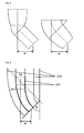
Fig. 6 shows the dilation of angular aperture in the meridian section of a toroidal angle rotator. The extreme ray hitting the inner circle dilates to a maximum value when the aperture cut the ray path exactly out of phase. Cutting the aperture at a different location does not significantly improve the situation. For this reason, the torus is of practical use only for redirecting radiation having an angular aperture near 90°. However with such a large angular aperture, the torus suffers from a higher average number of reflections. - b) Chaves and Collares-Pereira developed an angle rotator that is capable of redirecting radiation through any rotation angle while preserving angular aperture (in the meridian section) [3]. The angle rotator consists of three flat mirrors and one elliptic mirror (EAR, see
Fig. 10 left side; taken from [4]). Since the elliptic angle rotator preserves angular aperture, it may be used before or after a concentrating optic without loss of ideality (in the meridian section). - c) The Compound Parabolic Concentrator (CPC) is an ideal concentrator in two dimensions for an infinite source of half-angular aperture θacc. In revolved three-dimensional geometry, it falls short of ideality due to partial rejection of non-meridian (skew) rays.
- d) A light pipe (LP) is a simple extruded section which can be used to guide radiation. In the meridian section it preserves angular aperture and may therefore be used before and after a solar concentrator, see
Fig. 7 . - e) The CPC-TAR-LP consists of a CPC with the inlet placed at the focal plane. A torus is placed at the exit of the CPC to redirect radiation from the exit of the CPC. A light-pipe is used to gain further eccentricity. The inner radius of the torus is chosen as zero, since in general a higher eccentricity with a fewer number of reflections can be achieved when combining a small inner radius torus with a light-pipe than when using a large inner radius torus alone. The length of the light-pipe placed at the end of the torus is chosen to achieved a center-to-center eccentricity of 60 mm, see
Fig. 8 left side. - f) Due to the high number of reflections in the CPC-TAR-LP, the TAR-CPC was investigated. The TAR-CPC configuration can achieve a higher eccentricity with fewer reflections that the CPC-TAR-LP configuration since rotation is performed before the CPC such that the CPC length contributes to the eccentricity. It is expected that the TAR-CPC will suffer from a low acceptance efficiency due to dilation of the angular aperture by the torus, see
Fig. 8 right side. - g) The EAR-CPC has the advantages of the TAR-CPC but with the EAR preserving angular aperture thus hypothetically leading to a higher acceptance efficiency. Drawbacks are difficulties in manufacturability, reduced design flexibility as the EAR design is fixed by the angular aperture and rotation angle as opposed to the TAR where the inner radius can be chosen independent of the rotation angle, see
Fig. 10 right side. - h) Any two mirrors placed along lines of flow of a Lambertian radiator constitute an ideal concentrator in two dimensions. Considering the lines of flow of an inverted V-wedge receiver as in
Fig. 9 reveals some interesting concentrator profiles. The lines of flow are confocal parabolas with focus at the tip of the wedge. By placing mirrors along any two flowlines, an ideal eccentric concentrator with exit aperture rotated by anangle 90°- θc with an arbitrarily large eccentricity can be obtained. The main drawback of these designs is a high average number of reflections due to the high length to aperture (slenderness) ratio. To partially overcome this, the so-called Eccentric FlowLine Concentrator (EFLC) can be truncated on the inlet side with little loss of concentration and eccentricity.Fig. 9 shows a schematic drawing of an EFLC constructed from the lines offlow 200 from an inverted V-wedge receiver. Placing mirrors 201 along any two lines of flow constitute an ideal concentrator in two dimensions. The inlet side of the EFLC can be truncated to shorten the concentrator and reduce the average number of reflections without significant loss of concentration and eccentricity -
Fig. 1 to Fig. 3 andFig. 16 show asolar deflection device 1 according to the invention that in the following is referred to as tailored toroid concentrator (TTC). Such a TTC concentrates and redirects electromagnetic radiation and might be used for directing concentrated electromagnetic radiation particularly from a single stationary source particularly to a plurality of apertures of a multiple-cavity receiver, for example an array of cavities, each with an individual aperture. - The TTC is a tailored concentrator based on a torus with geometry modified to achieve ideal concentration at maximum optical efficiency. The TTC particularly comprises all or some of the following features:
- electromagnetic radiation is collected by a
circular inlet aperture 3 of radius ri, within a nominal half acceptance angle 9 (θ), and redirected to acircular exit aperture 4 with a radius ro or with adiameter 4d that is smaller than the radius ri ordiameter 3d of theinlet aperture 3 respectively, - the
exit aperture 4 is tilted by a rotation angle of φ, wherein said rotation angle corresponds to thelargest deflection angle 7, and wherein theexit aperture 4 is furthermore laterally displaced by an eccentricity ec, with respect to theinlet aperture 3, - the eccentricity ec and rotation angle φ may be chosen to achieve the required separation and inclination of the plurality of cavity apertures,
- the geometric concentration C= Ai/Ao is set equal to the theoretical limit of 1/sin2(θ) imposed by the three-dimensional conservation of étendue,
- the TTC features low average number of reflections (n), compared to composite devices comprised of existing optical components, thus minimizing power loses due to finite reflectivity of mirror surfaces,
- the optical efficiency ηoptical through the TTC may approach that of conventional non-imaging concentrators which only concentrate and do not redirect radiation,
- the geometry of the TTC is defined by a
curved line 5 that is particularly a circular arc centerline in the two-dimensional cross-section through the plane of symmetry of the TTC (as shown inFig. 2 ), - the geometric concentration C can be reduced from the theoretical limit by slightly increasing the
exit aperture diameter 4d, leading to an increase in optical efficiency ηoptical, - the three dimensional geometry is formed by a series of
circular cross-sections 6 cut at a deflection angle 7 (ϕ) with respect to theinlet aperture 3, - the normal of each
circular cross-section 6 is tangent to thecenterline 5 at the point of intersection, - the
diameter 6d or radius (r(ϕ)) of eachcircular cross-section 6 is defined by a function S, particularly a taper function S, with r = S(ϕ), where S is particularly an interpolant of linear, quadratic, or cubic form, - the mirror profiles may be tailored by changing the taper function S to maximize optical efficiency ηoptical,
- the inner Ri and outer radii Ro of the
solar deflection device 1 are chosen to meet the required eccentricity ec and rotation angle φ (see e.g.Fig. 5 ). - The construction of such a tailored toroidal concentrator particularly begins in the x-z plane with a
curved line 5, particularly a circular arc centerline covering a rotation angle φ and radius Rc centered at the origin as shown inFig. 2 . Theinlet aperture 3 extends along theinlet plane 3a along the x-y-axis. Thecircular inlet aperture 4 with a radius ri that is smaller than the radius of the circular arc centerline Rc, is centered at the start of said curved line 5 (defining a deflection angle of ϕ = 0), laying in the x-y plane. The center-to-center eccentricity ec of the TTC is given by ec = Rc(1-cos(φ) ). Eachdeflection angle 7 in the range between 0 ≤ ϕ ≤ φ defines across-section 6 that is comprised in aplane 6a that intersects theinlet plane 3a enclosing saiddeflection angle 7 and that is perpendicular to saidcurved line 5 at the point of intersection with thecurved line 5. Thecircular exit aperture 4 with a radius ro that is smaller than the radius of the inlet aperture ri, ro < ri < rc , is centered at the end (ϕ = ϕ) of thecurved line 5 through a plane whose normal is tangent to the end of thecurved line 5. The exit aperture radius ro is nominally chosen as ri = ro sin(θ), corresponding to the theoretical limit of geometric concentration C for partially collimated incident radiation of nominal half acceptance angle θ. Selecting a slightly larger exit aperture radius ro may be beneficial in improving optical efficiency η optical , with a slight reduction from the theoretical maximum geometric concentration C. Thereflective surface 2b of the TTC is defined by a series ofcircular cross-sections 6 from the inlet to exitaperture 3 onplanes 6a whose normals n are tangent to thecurved line 5 at the intersection point where therespective plane 6a intersects the curved line, as shown inFig. 3 . The "taper" of thesolar deflection device 1 is the function S describing the radius r of eachcircular cross section 6 as a function of the deflection angle 7 (also referred to as ϕ). The complete parametric equations of the surface in three dimensions, for an origin placed at the center of thecurved line 5, with x-z as the symmetry plane of the TTC, are:


for 0 ≤ ϕ ≤ φ, and 0 ≤ ψ < 2π. The resulting shape is a surface from thecircular inlet aperture 3 to thecircular exit aperture 4 through thecircular cross-sections 6 of radius r = S(ϕ). - Various taper functions S are possible, but generally interpolating functions are used. Depending on the number of interpolation points (also termed knots) used in addition to the endpoints (ϕ = 0, ri) and (ϕ = φ, ro), different interpolation functions (also termed interpolants) may be used. The simplest interpolant is (with zero additional knots) the linear interpolant r(ϕ) = r i - (r i - r o ) ϕ/φ. An additional interpolation point may be defined at the "waist" of the device at a deflection angle φw (given a nominal value of ½φ) and radius rw. It is then possible to define a piecewise linear spline, a parabola (quadratic), or piecewise cubic spline through the three knots. For φw = ½φ), a value of rw = ½(ri + ro) produces a linear interpolant for a spline of any degree. The waist control point can be tailored to maximize the optical transfer efficiency of the TTC. Additional knots provide additional degrees of freedom to tailor the TTC.
- Due to its high degree of smoothness, the cubic spline is a preferred interpolant for the taper function S. For one additional interpolation point at the waist, a natural cubic spline S(ϕ) may be fitted through knots I(0, ri), W(φw, rw) and O(φo, ro). The 3-point spline has two segments: the first segment ranges from the inlet to the waist, and second segment ranges from the waist to the exit, with second derivatives set to zero at the two ends (natural spline), and first and second derivatives matched at W. The interpolant for the jth segment has the form:



- One way to design such a TTC is to choose the inlet (and/or exit) aperture for maximum concentration C = 1/sin2(θ), and subsequently tailor the waist radius rw at half the rotation angle φ to yield the highest optical efficiency η optical.
- The particularly highest optical efficiency η optical can be estimated for example by a computer simulation.
- Ray-tracing simulations were performed in LightTools 7.1.0 using solid model geometries built in SolidWorks 2011. The radiation source was modelled as a Lambertian disk of radius 2.5 m at a distance of 2.5 m from the focal plane (i.e. subtending a rim angle of 45°). A low number of rays (25 000) were traced for each simulation to facilitate the investigation of many designs. The estimated error on the power reaching the exit plane was below 1% for all simulations (see
Fig. 15 ) - The results are compared to other solar deflection devices.
- The acceptance efficiency of a 45° three dimensional Compound parabolic concentrator (CPC) is used as a reference. As mentioned above, the CPC is an ideal concentrator in two dimensions for an infinite source of half-angular aperture θacc. In revolved three-dimensional geometry, it falls short of ideality due to partial rejection of non-meridian (skew) rays.
- In
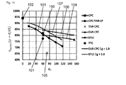
Fig. 11 it is shown that the EFLCs 101 (represented by the diamond-shaped markers) have the highest acceptance efficiency ηacc due to their ideal two dimensional construction. For large eccentricity ec (i.e. very slender designs), theEFLC 101 actually surpasses the three-dimensional CPC 102 (represented by the square-shaped marker at 0 degree ec) in terms of acceptance efficiency. The CPC-TAR-LP design 103 (represented by the circular shaped marker) also has a very high acceptance efficiency ηacc which should essentially be equivalent to that of theCPC 102 alone since both the TAR and the LP are ideal in three dimensions. TheTTC 100 shown (represented the square-shaped marker at 60°ec) has an optimized waist width and performs better than expected considering that it is not constructed from an ideal two-dimensional geometry. The EAR-CPC 104 performs reasonably well but is the lowest of the high-performance designs due to slight dilation of angular aperture through the EAR in 3D. The TAR-CPC 105 performs poorly due to significant dilation of angular aperture by the TAR. Furthermore the results of an EAR-CPC 106 and anEFLC 107 design each with a geometric concentration C of 1.8 are shown. - In
Fig. 12 it is shown that the long slender designs, particularly theEFLC 101 and the CPC-TAR-LP 103 have a very high average number of reflections (n) for high eccentricities ec. The EAR-CPC 104 andTTC 100 designs have a comparable average number of reflections 〈n〉. The TAR-CPC 105 has the lowest average number of reflections 〈n〉 owing to its extremely compact design. - The combined effect of the acceptance efficiency ηacc and the average number of reflections 〈n〉 is shown in
Fig. 13 andFig. 14 . TheEFLC 101 is a promising design for low eccentricities ec but is impractical for high eccentricities ec due to an increased average number of reflections 〈n〉. The EAR-CPC 104 is a potential candidate for medium eccentricities ec, but is long for a given aperture diameter. TheTTC 100 is particularly the best design for high eccentricities ec. Furthermore the results of an EAR-CPC 106 and anEFLC 107 design each with a geometric concentration C of 1.8 are shown. -
- Inlet aperture diameter, D¡ = 40 mm;
- Outlet aperture diameter, Do = 30 mm;
- Eccentricity ec = 50 mm;
- Normalized eccentricity, ec /Di = 1.25;
- Geometric concentration, C = (Di/Do)2 =16/9≈1.78;
- Maximal acceptance angle, θmax = sin-1(C-0.5) = 48.6°;
- Nominal half acceptance angle, θ = 45°;
- Etendue loss, sin2θiS/sin2θmax = 0.94;
- Outlet inclination, T = 45°
- Simulations were performed with a Lambertian disk source approximating the geometry of a solar simulator.
- Focal length, f = 1 m;
- Source diameter, Dmax = 2.25 m;
- Maximum rim angle, ϕmax = tan-1(Dmax/2f) = 48.4°;
- Nominal rim angle, Φnom = 45°;
- Source diameter at nominal rim angle, Dnom = 2 m;
- Aim area diameter, D¡ = 40 mm
- Three different geometric constructions with an increasing number of degrees-of-freedom were investigated. In all cases, the three dimensional geometry was obtained by lofting from the circular inlet aperture to the circular outlet aperture along the specified guide curves.
- The baseline design consists of a
circular centerline 5 with a radius Rc which governs the position of the inlet andoutlet aperture - The
Spline 1 design utilizes the height H and eccentricity ec to position the inlet andoutlet apertures guide profiles 300, 301 - that are the cross-sectional lines of thefunnel 2 representing thefunnel wall 2a - are natural cubic splines passing through the inlet andoutlet aperture knot 302 placed between a beginning and an end of the respective guide profile, particularly at the "waist" of thesolar deflection device 1. There are three degrees of freedom which may be used as optimization parameters. The optimization parameters are particularly given by the radius Rw from one of the guide profiles 300, the radius rw of thefunnel 2 at a particular deflection angle and the height H of thefunnel 2 as shown inFig. 4 . - The
Spline 2 design is similar to theSpline 1 design, but the placement of the knots is not restricted to be collinear with the origin. The twoguide profiles solar deflection device 1 may be chosen independently. There are five degrees of freedom which may be used as optimization parameters. The optimization parameters are particularly given by - the radius of the line in the x-z plane from the origin to the interior knot of the inner guide profile Ri,,
- the same but for the outer guide profile Ro,
- a first deflection angle τi of the line in the x-z plane from the origin to the interior knot of the
inner guide profile 300, - a second deflection angle τo of the line in the x-z plane from the origin to the outer knot of the
outer guide profile 301, and - the height H of the
solar deflection device 1 device as shown inFig. 5 . - Optimization was performed to maximize optical efficiency for a reflectivity of 95% at the nominal acceptance angle using 105 rays. The "alternate engine" in LightTools was used with an exit criterion of less than a 10-5% improvement on the objective function. However, it is likely that the noise floor of the MC simulation provides a less strict exit criterion.
- After the optimization, the resulting designs were traced with 106 rays. The results for an incident radiant power of Qi = 100 W, are shown below. The values of the output power Qo are equal to the percent optical efficiency of the design.
ρ=1 p=0.95 ρ=0.9 <n> Qo Qrej Qabs Qo Qrej Qabs Qo Qrej Qabs Baseline 3.57 99.16 0.93 0.00 83.04 0.26 16.70 69.85 0.08 30.07 Baseline* 3.79 99.16 0.93 0.00 82.12 0.26 17.62 68.42 0.08 31.50 Spline 13.05 98.42 1.58 0.00 84.91 0.69 14.40 73.27 0.32 26.42 Spline 22.82 98.78 1.22 0.00 95.94 0.71 13.35 74.71. 0.41 24.88 * with a 5 mm light pipe at the exit of the concentrator - The design parameters for the optimized designs are given below:
Spline 1Spline 2 Rw 125.42 Ri 123.43 rw 39.77 Ro 157.31 H 98.40 Ti 20.20° To 40.14° H 97.39 -
- [1] M. Collares-Pereira, et al., (1985). "Redirecting concentrated radiation," Proceedings of SPIE, 2538, pp. 131-135.
- [2] A. Rabl, (1977). "Radiation transfer through specular passages - a simple approximation," International Journal of Heat and Mass Transfer, 20, pp. 323-330.
- [3] J. Chaves and M. Collares-Pereira, (2002). "Ideal concentrators with gaps," Applied Optics, 41, pp. 1267-1276.
- [4] J. Chaves, Introduction to nonimaging optics: CRC Press, 2008.
-
- 1
- solar deflection device
- 2
- funnel
- 2a
- funnel wall
- 2b
- reflective surface
- 3
- inlet aperture
- 3a
- inlet plane
- 3b
- inlet area
- 3c
- center of inlet area
- 3d
- diameter of inlet aperture
- 4
- exit aperture
- 4a
- exit plane
- 4b
- exit area
- 4c
- center of exit area
- 4d
- diameter of exit aperture
- 5
- curved line
- 6
- cross-section
- 6a
- plane of cross-section
- 6b
- are of cross-section
- 6d
- diameter of cross-section
- 7
- deflection angle
- 9
- nominal half acceptance angle
- 100
- TTC / Tailored Toroidal Concentrator design
- 101
- EFLC design
- 102
- CPC / Compound Parabolic Concentrator design
- 103
- CPC-TAR-LP design
- 104
- EAR-CPC design
- 105
- TAR-CPC design
- 106
- EAR-CPC design for C = 1.8
- 107
- EFLC design for C = 1.8
- 200
- lines of flow
- 201
- mirrors
- 300
- guide profile
- 301
- guide profile
- 302
- knot
- A
- optical axis
- D¡
- diameter of inlet aperture
- Do
- diameter of exit aperture
- ri
- radius of inlet aperture
- ro
- radius of exit aperture
- H
- height of solar deflection device
- rw
- waist radius
- ec
- eccentricity
- F
- focal plane
- S
- function
- φ
- maximum deflection angle
Claims (14)
- Solar deflection device (1) comprising at least the following components:- a hollow funnel (2), comprising a funnel wall (2a) that comprises a reflective surface (2b) on an inside of the funnel (2) for reflecting electromagnetic radiation,- an inlet aperture (3) of said funnel (2), wherein the inlet aperture (3) extends within an inlet plane (3a),- an exit aperture (4) of said funnel (2), wherein the exit aperture (4) extends within an exit plane (4a) and wherein the area (4b) enclosed by the exit aperture (4) has a different size than the area (3b) enclosed by the inlet aperture (3),- a curved line that (5) extends from the center (3c) of the inlet aperture (3) to the center (4c) of the exit aperture (4), wherein for each plane (6a) that intersects said curved line (5) perpendicularly, the reflective surface (2b) of the funnel wall (2a) has a cross-section (6) within said plane (6a), wherein said cross-section (6) encloses an area (6b) and is centered around the curved line (5),- a deflection angle (7) that is enclosed between said plane (6a) and the inlet plane (3a).
- Solar deflection device according to claim 1, wherein the area (3b, 4b, 6b) enclosed by the inlet aperture (3), the exit aperture (4) and/or the cross-section (6) has an oval, particularly a circular shape or elliptical shape.
- Solar deflection device according to claim 1 or 2, wherein at essentially each point of the curved line (5), the curved line (5) has a curvature that is larger than zero.
- Solar deflection device according to one of the preceding claims, wherein said curved line (5) is an arc line, particularly a circular arc line with a radius (Rc), or a non-parabolic line.
- Solar deflection device according to one of the preceding claims, wherein the aperture area (3b) of the inlet aperture (3) is larger than the aperture area (4b) of the exit aperture (4).
- Solar deflection device according to one of the preceding claims, wherein the size of the enclosed area (6b) of the cross-section (6), particularly the diameter (6d) of the cross-section (6) is a continuous function (S) of said deflection angle (7).
- Solar deflection device according to claim 6, wherein the function (S) is continuously differentiable at least once, particularly twice, more particularly three times.
- Solar deflection device according to one of the claims 6 or 7, wherein the function (S) is a monotonic function, particularly a strictly monotonic function.
- Solar deflection device according to one of the claims 6 to 8, wherein the function (S) is an interpolating function, including the diameter (3d) of the inlet aperture (3) and the diameter (4d) of the exit aperture (4) as interpolation points.
- Solar deflection device according to one of the claims 6 to 9, wherein the function (S) comprises a spline, particularly a linear, a quadratic or a cubic, particularly a natural cubic spline.
- Solar deflection device according to one of the claims 9 or 10, wherein the function (S) comprises or is a piecewise particularly natural cubic spline connecting a plurality of interpolation points, wherein particularly the size of the enclosed area (3b), particularly the diameter (3d), of the inlet aperture (3) and the size of the enclosed area (4b), particularly the diameter (4d) of the exit aperture (4) are two of the plurality of interpolation points and wherein particularly a third interpolation point corresponds to the size of the enclosed area (6b), particularly to the diameter (6d) of the cross-section (6).
- Solar deflection device according to one of the preceding claims, wherein the solar deflection device comprises a nominal half acceptance angle (9) between 30° and 60°, preferably 45°.
- Solar deflection device according to one of the preceding claims, wherein the inlet aperture (3) and the exit aperture (4) enclose a deflection angle (7) between 30° and 60°, preferably 45°.
- Solar deflection device according to one of the preceding claims, wherein the inlet plane (3a) and the exit plane (4a) are perpendicular to the curved line (5).
Priority Applications (4)
| Application Number | Priority Date | Filing Date | Title |
|---|---|---|---|
| EP15159194.8A EP3070415A1 (en) | 2015-03-16 | 2015-03-16 | Solar deflection device |
| EP16712753.9A EP3271665A1 (en) | 2015-03-16 | 2016-03-14 | Solar deflection device |
| US15/558,584 US20180058725A1 (en) | 2015-03-16 | 2016-03-14 | Solar deflection device |
| PCT/EP2016/055443 WO2016146576A1 (en) | 2015-03-16 | 2016-03-14 | Solar deflection device |
Applications Claiming Priority (1)
| Application Number | Priority Date | Filing Date | Title |
|---|---|---|---|
| EP15159194.8A EP3070415A1 (en) | 2015-03-16 | 2015-03-16 | Solar deflection device |
Publications (1)
| Publication Number | Publication Date |
|---|---|
| EP3070415A1 true EP3070415A1 (en) | 2016-09-21 |
Family
ID=52686175
Family Applications (2)
| Application Number | Title | Priority Date | Filing Date |
|---|---|---|---|
| EP15159194.8A Withdrawn EP3070415A1 (en) | 2015-03-16 | 2015-03-16 | Solar deflection device |
| EP16712753.9A Withdrawn EP3271665A1 (en) | 2015-03-16 | 2016-03-14 | Solar deflection device |
Family Applications After (1)
| Application Number | Title | Priority Date | Filing Date |
|---|---|---|---|
| EP16712753.9A Withdrawn EP3271665A1 (en) | 2015-03-16 | 2016-03-14 | Solar deflection device |
Country Status (3)
| Country | Link |
|---|---|
| US (1) | US20180058725A1 (en) |
| EP (2) | EP3070415A1 (en) |
| WO (1) | WO2016146576A1 (en) |
Citations (5)
| Publication number | Priority date | Publication date | Assignee | Title |
|---|---|---|---|---|
| US3899672A (en) * | 1974-02-19 | 1975-08-12 | Univ Chicago | Solar energy collection |
| US20080066799A1 (en) * | 2003-10-30 | 2008-03-20 | Pratt & Whitney Rocketdyne, Inc. | Optical Concentrator for Solar Cell Electrical Power Generation |
| WO2009001106A2 (en) * | 2007-06-25 | 2008-12-31 | Sunsense Ltd. | System and methods of utilizing solar energy |
| EP2348342A1 (en) * | 2010-01-07 | 2011-07-27 | Sharp Kabushiki Kaisha | Non-Tracked Low Concentration Solar Concentrator, Solar Concentrator Array and Waveguide Concentrator |
| US20120138047A1 (en) * | 2009-05-08 | 2012-06-07 | Arthur Ashkin | Compound Collector System For Solar Energy Concentration |
-
2015
- 2015-03-16 EP EP15159194.8A patent/EP3070415A1/en not_active Withdrawn
-
2016
- 2016-03-14 US US15/558,584 patent/US20180058725A1/en not_active Abandoned
- 2016-03-14 WO PCT/EP2016/055443 patent/WO2016146576A1/en not_active Ceased
- 2016-03-14 EP EP16712753.9A patent/EP3271665A1/en not_active Withdrawn
Patent Citations (5)
| Publication number | Priority date | Publication date | Assignee | Title |
|---|---|---|---|---|
| US3899672A (en) * | 1974-02-19 | 1975-08-12 | Univ Chicago | Solar energy collection |
| US20080066799A1 (en) * | 2003-10-30 | 2008-03-20 | Pratt & Whitney Rocketdyne, Inc. | Optical Concentrator for Solar Cell Electrical Power Generation |
| WO2009001106A2 (en) * | 2007-06-25 | 2008-12-31 | Sunsense Ltd. | System and methods of utilizing solar energy |
| US20120138047A1 (en) * | 2009-05-08 | 2012-06-07 | Arthur Ashkin | Compound Collector System For Solar Energy Concentration |
| EP2348342A1 (en) * | 2010-01-07 | 2011-07-27 | Sharp Kabushiki Kaisha | Non-Tracked Low Concentration Solar Concentrator, Solar Concentrator Array and Waveguide Concentrator |
Non-Patent Citations (4)
| Title |
|---|
| A. RABL: "Radiation transfer through specular passages - a simple approximation", INTERNATIONAL JOURNAL OF HEAT AND MASS TRANSFER, vol. 20, 1977, pages 323 - 330 |
| J. CHAVES: "Introduction to nonimaging optics", 2008, CRC PRESS |
| J. CHAVES; M. COLLARES-PEREIRA: "Ideal concentrators with gaps", APPLIED OPTICS, vol. 41, 2002, pages 1267 - 1276 |
| M. COLLARES-PEREIRA ET AL.: "Redirecting concentrated radiation", PROCEEDINGS OF SPIE, vol. 2538, 1985, pages 131 - 135 |
Also Published As
| Publication number | Publication date |
|---|---|
| EP3271665A1 (en) | 2018-01-24 |
| US20180058725A1 (en) | 2018-03-01 |
| WO2016146576A1 (en) | 2016-09-22 |
Similar Documents
| Publication | Publication Date | Title |
|---|---|---|
| Dähler et al. | Optical design and experimental characterization of a solar concentrating dish system for fuel production via thermochemical redox cycles | |
| US7160522B2 (en) | Device for concentrating or collimating radiant energy | |
| Qiu et al. | Study on optical and thermal performance of a linear Fresnel solar reflector using molten salt as HTF with MCRT and FVM methods | |
| US7697219B2 (en) | Non-imaging facet based optics | |
| Crisostomo et al. | Spectral splitting strategy and optical model for the development of a concentrating hybrid PV/T collector | |
| US7688525B2 (en) | Hybrid primary optical component for optical concentrators | |
| EP1266255B1 (en) | Method of designing and manufacturing high efficiency non-imaging optics | |
| US6021007A (en) | Side-collecting lightguide | |
| EP2169728A2 (en) | Method and system for light collection and light energy converting apparatus | |
| EP1613901B1 (en) | Solar concentrating system with corrected total reflection reflectors | |
| TW201110386A (en) | Non-imaging light concentrator | |
| Ma et al. | Analysis on an optimal transmittance of Fresnel lens as solar concentrator | |
| US7607429B2 (en) | Multistage system for radiant energy flux transformation comprising an array of slat-like reflectors | |
| US20100024868A1 (en) | Solar radiation collector | |
| US20100165495A1 (en) | Collection optic for solar concentrating wedge | |
| EP2433164B1 (en) | Optimizing total internal reflection multilayer optics through material selection | |
| Hernández et al. | High-performance Köhler concentrators with uniform irradiance on solar cell | |
| Chemisana et al. | Design and optical performance of a nonimaging Fresnel transmissive concentrator for building integration applications | |
| Mojiri et al. | Spectrally splitting hybrid photovoltaic/thermal receiver design for a linear concentrator | |
| US20180051913A1 (en) | Solar radiation guidance device | |
| US20180058725A1 (en) | Solar deflection device | |
| CN104350676B (en) | The concentrator of polychromatic light | |
| Tsai | Enhanced irradiance distribution on solar cell using optimized variable-focus-parabolic concentrator | |
| Mo¨ ller et al. | SOLREF: Development of an advanced solar high-temperature reformer | |
| Groulx et al. | Ray-tracing analysis of a two-stage solar concentrator |
Legal Events
| Date | Code | Title | Description |
|---|---|---|---|
| PUAI | Public reference made under article 153(3) epc to a published international application that has entered the european phase |
Free format text: ORIGINAL CODE: 0009012 |
|
| AK | Designated contracting states |
Kind code of ref document: A1 Designated state(s): AL AT BE BG CH CY CZ DE DK EE ES FI FR GB GR HR HU IE IS IT LI LT LU LV MC MK MT NL NO PL PT RO RS SE SI SK SM TR |
|
| AX | Request for extension of the european patent |
Extension state: BA ME |
|
| STAA | Information on the status of an ep patent application or granted ep patent |
Free format text: STATUS: THE APPLICATION IS DEEMED TO BE WITHDRAWN |
|
| 18D | Application deemed to be withdrawn |
Effective date: 20170322 |