EP3070387A1 - Flexible coupling with rotational capability - Google Patents
Flexible coupling with rotational capability Download PDFInfo
- Publication number
- EP3070387A1 EP3070387A1 EP16161114.0A EP16161114A EP3070387A1 EP 3070387 A1 EP3070387 A1 EP 3070387A1 EP 16161114 A EP16161114 A EP 16161114A EP 3070387 A1 EP3070387 A1 EP 3070387A1
- Authority
- EP
- European Patent Office
- Prior art keywords
- convolution
- coupling
- section
- rotatable connection
- elbow
- Prior art date
- Legal status (The legal status is an assumption and is not a legal conclusion. Google has not performed a legal analysis and makes no representation as to the accuracy of the status listed.)
- Granted
Links
Images


Classifications
-
- F—MECHANICAL ENGINEERING; LIGHTING; HEATING; WEAPONS; BLASTING
- F25—REFRIGERATION OR COOLING; COMBINED HEATING AND REFRIGERATION SYSTEMS; HEAT PUMP SYSTEMS; MANUFACTURE OR STORAGE OF ICE; LIQUEFACTION SOLIDIFICATION OF GASES
- F25B—REFRIGERATION MACHINES, PLANTS OR SYSTEMS; COMBINED HEATING AND REFRIGERATION SYSTEMS; HEAT PUMP SYSTEMS
- F25B41/00—Fluid-circulation arrangements
- F25B41/20—Disposition of valves, e.g. of on-off valves or flow control valves
-
- F—MECHANICAL ENGINEERING; LIGHTING; HEATING; WEAPONS; BLASTING
- F16—ENGINEERING ELEMENTS AND UNITS; GENERAL MEASURES FOR PRODUCING AND MAINTAINING EFFECTIVE FUNCTIONING OF MACHINES OR INSTALLATIONS; THERMAL INSULATION IN GENERAL
- F16L—PIPES; JOINTS OR FITTINGS FOR PIPES; SUPPORTS FOR PIPES, CABLES OR PROTECTIVE TUBING; MEANS FOR THERMAL INSULATION IN GENERAL
- F16L25/00—Construction or details of pipe joints not provided for in, or of interest apart from, groups F16L13/00 - F16L23/00
- F16L25/0018—Abutment joints
-
- F—MECHANICAL ENGINEERING; LIGHTING; HEATING; WEAPONS; BLASTING
- F16—ENGINEERING ELEMENTS AND UNITS; GENERAL MEASURES FOR PRODUCING AND MAINTAINING EFFECTIVE FUNCTIONING OF MACHINES OR INSTALLATIONS; THERMAL INSULATION IN GENERAL
- F16L—PIPES; JOINTS OR FITTINGS FOR PIPES; SUPPORTS FOR PIPES, CABLES OR PROTECTIVE TUBING; MEANS FOR THERMAL INSULATION IN GENERAL
- F16L27/00—Adjustable joints; Joints allowing movement
- F16L27/08—Adjustable joints; Joints allowing movement allowing adjustment or movement only about the axis of one pipe
-
- F—MECHANICAL ENGINEERING; LIGHTING; HEATING; WEAPONS; BLASTING
- F16—ENGINEERING ELEMENTS AND UNITS; GENERAL MEASURES FOR PRODUCING AND MAINTAINING EFFECTIVE FUNCTIONING OF MACHINES OR INSTALLATIONS; THERMAL INSULATION IN GENERAL
- F16L—PIPES; JOINTS OR FITTINGS FOR PIPES; SUPPORTS FOR PIPES, CABLES OR PROTECTIVE TUBING; MEANS FOR THERMAL INSULATION IN GENERAL
- F16L27/00—Adjustable joints; Joints allowing movement
- F16L27/08—Adjustable joints; Joints allowing movement allowing adjustment or movement only about the axis of one pipe
- F16L27/0804—Adjustable joints; Joints allowing movement allowing adjustment or movement only about the axis of one pipe the fluid passing axially from one joint element to another
- F16L27/0837—Adjustable joints; Joints allowing movement allowing adjustment or movement only about the axis of one pipe the fluid passing axially from one joint element to another the joint elements being bends
- F16L27/0845—Adjustable joints; Joints allowing movement allowing adjustment or movement only about the axis of one pipe the fluid passing axially from one joint element to another the joint elements being bends forming an angle of 90 degrees
-
- F—MECHANICAL ENGINEERING; LIGHTING; HEATING; WEAPONS; BLASTING
- F16—ENGINEERING ELEMENTS AND UNITS; GENERAL MEASURES FOR PRODUCING AND MAINTAINING EFFECTIVE FUNCTIONING OF MACHINES OR INSTALLATIONS; THERMAL INSULATION IN GENERAL
- F16L—PIPES; JOINTS OR FITTINGS FOR PIPES; SUPPORTS FOR PIPES, CABLES OR PROTECTIVE TUBING; MEANS FOR THERMAL INSULATION IN GENERAL
- F16L27/00—Adjustable joints; Joints allowing movement
- F16L27/08—Adjustable joints; Joints allowing movement allowing adjustment or movement only about the axis of one pipe
- F16L27/0861—Arrangements of joints with one another and with pipes or hoses
-
- F—MECHANICAL ENGINEERING; LIGHTING; HEATING; WEAPONS; BLASTING
- F16—ENGINEERING ELEMENTS AND UNITS; GENERAL MEASURES FOR PRODUCING AND MAINTAINING EFFECTIVE FUNCTIONING OF MACHINES OR INSTALLATIONS; THERMAL INSULATION IN GENERAL
- F16L—PIPES; JOINTS OR FITTINGS FOR PIPES; SUPPORTS FOR PIPES, CABLES OR PROTECTIVE TUBING; MEANS FOR THERMAL INSULATION IN GENERAL
- F16L27/00—Adjustable joints; Joints allowing movement
- F16L27/10—Adjustable joints; Joints allowing movement comprising a flexible connection only
- F16L27/107—Adjustable joints; Joints allowing movement comprising a flexible connection only the ends of the pipe being interconnected by a flexible sleeve
- F16L27/11—Adjustable joints; Joints allowing movement comprising a flexible connection only the ends of the pipe being interconnected by a flexible sleeve the sleeve having the form of a bellows with multiple corrugations
- F16L27/111—Adjustable joints; Joints allowing movement comprising a flexible connection only the ends of the pipe being interconnected by a flexible sleeve the sleeve having the form of a bellows with multiple corrugations the bellows being reinforced
-
- F—MECHANICAL ENGINEERING; LIGHTING; HEATING; WEAPONS; BLASTING
- F16—ENGINEERING ELEMENTS AND UNITS; GENERAL MEASURES FOR PRODUCING AND MAINTAINING EFFECTIVE FUNCTIONING OF MACHINES OR INSTALLATIONS; THERMAL INSULATION IN GENERAL
- F16L—PIPES; JOINTS OR FITTINGS FOR PIPES; SUPPORTS FOR PIPES, CABLES OR PROTECTIVE TUBING; MEANS FOR THERMAL INSULATION IN GENERAL
- F16L43/00—Bends; Siphons
-
- F—MECHANICAL ENGINEERING; LIGHTING; HEATING; WEAPONS; BLASTING
- F16—ENGINEERING ELEMENTS AND UNITS; GENERAL MEASURES FOR PRODUCING AND MAINTAINING EFFECTIVE FUNCTIONING OF MACHINES OR INSTALLATIONS; THERMAL INSULATION IN GENERAL
- F16L—PIPES; JOINTS OR FITTINGS FOR PIPES; SUPPORTS FOR PIPES, CABLES OR PROTECTIVE TUBING; MEANS FOR THERMAL INSULATION IN GENERAL
- F16L43/00—Bends; Siphons
- F16L43/008—Bends; Siphons made from plastic material
-
- F—MECHANICAL ENGINEERING; LIGHTING; HEATING; WEAPONS; BLASTING
- F16—ENGINEERING ELEMENTS AND UNITS; GENERAL MEASURES FOR PRODUCING AND MAINTAINING EFFECTIVE FUNCTIONING OF MACHINES OR INSTALLATIONS; THERMAL INSULATION IN GENERAL
- F16L—PIPES; JOINTS OR FITTINGS FOR PIPES; SUPPORTS FOR PIPES, CABLES OR PROTECTIVE TUBING; MEANS FOR THERMAL INSULATION IN GENERAL
- F16L51/00—Expansion-compensation arrangements for pipe-lines
- F16L51/02—Expansion-compensation arrangements for pipe-lines making use of a bellows or an expansible folded or corrugated tube
- F16L51/025—Expansion-compensation arrangements for pipe-lines making use of a bellows or an expansible folded or corrugated tube with several corrugations
- F16L51/026—Expansion-compensation arrangements for pipe-lines making use of a bellows or an expansible folded or corrugated tube with several corrugations with interior reinforcement
-
- F—MECHANICAL ENGINEERING; LIGHTING; HEATING; WEAPONS; BLASTING
- F24—HEATING; RANGES; VENTILATING
- F24F—AIR-CONDITIONING; AIR-HUMIDIFICATION; VENTILATION; USE OF AIR CURRENTS FOR SCREENING
- F24F13/00—Details common to, or for air-conditioning, air-humidification, ventilation or use of air currents for screening
- F24F13/02—Ducting arrangements
- F24F13/0209—Ducting arrangements characterised by their connecting means, e.g. flanges
-
- F—MECHANICAL ENGINEERING; LIGHTING; HEATING; WEAPONS; BLASTING
- F25—REFRIGERATION OR COOLING; COMBINED HEATING AND REFRIGERATION SYSTEMS; HEAT PUMP SYSTEMS; MANUFACTURE OR STORAGE OF ICE; LIQUEFACTION SOLIDIFICATION OF GASES
- F25B—REFRIGERATION MACHINES, PLANTS OR SYSTEMS; COMBINED HEATING AND REFRIGERATION SYSTEMS; HEAT PUMP SYSTEMS
- F25B13/00—Compression machines, plants or systems, with reversible cycle
Definitions
- the present invention relates generally to couplings and, more particularly, to a coupling for an air conditioning system.
- Air conditioning systems for aircraft are often comprised of many different modules.
- the different modules can perform different functions, and certain modules are connected to other modules in order to execute the processes necessary to regulate the environment inside of an aircraft. Such an arrangement involves fluids being transferred from one module to another, so couplings are present between the modules in order for this to occur.
- air conditioning systems can have many modules, the modules can be affixed to different portions of the aircraft's structure. There are many forces exerted upon and within the aircraft during movement on the ground and through the air, such as dynamic, aerodynamic, and thermal forces. These forces can be transmitted through the aircraft's structure, causing the structure to be displaced in various directions at different locations. Therefore, for example, if two components are affixed to the aircraft structure at different locations, then the distance and orientation between them can vary depending on the loading of the aircraft structure at a given time.
- a coupling includes a body with two ends and a bore.
- Each end section includes a rotatable connection and a convolution, and there is a bent elbow section between the end sections.
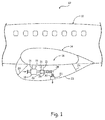
- FIG. 1 is a cut-away view of aircraft 10.
- Aircraft 10 includes airframe 12, wing 14, and air conditioning system 16.
- Air conditioning system 16 includes compressor motor assembly 18, diverter valve 20, and overboard exhaust 22.
- Wing 14 is connected to airframe 12, and compressor motor 18 and diverter valve 20 are connected to wing 14 using tie rods 21.
- Overboard exhaust 22 is connected to body fairing 23 which is connected to airframe 12 using tie rods 24.
- Compressor motor assembly 18 is fluidly connected to the atmosphere and to diverter valve 20 so that cooling air can flow past the compressor motor (not shown) inside of compressor motor assembly 18.
- Diverter valve 20 is fluidly connected to the primary heat exchanger fan (not shown) and to overboard exhaust 22.
- Diverter valve 20 is a 3-way valve that can send air from compressor motor assembly 18 to either the primary heat exchanger fan or overboard exhaust 22.
- Overboard exhaust 22 is also fluidly connected to the atmosphere.
- diverter valve 20 is fluidly connected to overboard exhaust 22 via extension 26, coupling 28, and extension 30.
- diverter valve 20 directs air from compressor motor assembly 18 to the primary heat exchanger fan because this fan pulls air from the atmosphere so that there is air flow through compressor motor assembly 18.
- diverter valve 20 directs air from compressor motor assembly 18 to overboard exhaust 22. This is because the air from the atmosphere is coming in from the ram scoop (not shown) and is sufficiently pressurized to flow through compressor motor assembly 18 on its own.
- air conditioning system 16 flows fluid through coupling 28 at a pressure higher than 0 kPa (0 psi) and lower than 35 kPa (5 psi) above atmospheric pressure.
- FIG. 2A is a side cross-sectional view of coupling 28, and FIGS. 2B and 2C are close-up views of coupling 28.
- Coupling 28 is configured to allow for the aforementioned relative movement of diverter valve 20 and overboard exhaust 22 (both shown in FIG. 1 ).
- the ability to remain attached to extension 26 and extension 30 while they change positions is due to coupling 28 being comprised of an elastomeric material and having a configuration that includes convolutions 32A and 32B and rotatable connections 34A and 34B.
- coupling 28 includes body 36 with bore 38 extending through body 36 from end 40A to end 40B.
- Body 36 has three sections including end section 42A, end section 42B, and elbow 44, with elbow 44 being positioned between end sections 42A and 42B.
- End sections 42A and 42B are mostly straight sections of coupling 28 that include rotatable connections 34A and 34B at ends 40A and 40B, respectively.
- End sections 42A and 42B also include two of convolutions 32A and 32B between rotatable connections 34A and 34B and elbow 44, respectively.
- Elbow 44 is a bent section of body 36 that changes the orientation of bore 38 between 45 degrees and 135 degrees, or between 60 degrees and 120 degrees, or between 75 degrees and 105 degrees, or, as shown in FIG. 2A , about 90 degrees (i.e. between 85 degrees and 95 degrees).
- Rotatable connections 34A and 34B interface with extensions 26 and 30 (both shown in FIG. 1 ), respectively, and allow rotation of coupling 28 with respect to extension 26 and/or extension 30 while maintaining sealed connections.
- rotatable connections 34A and 34B are designed in accordance with the Society of Automotive Engineers (SAE) AS 1650 standard. Not all the components of such rotatable connections are shown in FIG. 2A , but seals 46A and 46B have been included. Seals 46A and 46B are low friction seals comprised of rubber that can be coated with polytetrafluoroethylene.
- SAE AS 1650 standard rotatable connections allow for 360 degrees of rotation, although rotatable connections 34A and 34B may be configured to allow for only 30 degrees of rotation in some embodiments. Such embodiments are possible because the relative displacement of extension 26 to extension 30 can be restricted to eliminate the need for higher degrees of rotation of coupling 28.
- each convolution 32A and 32B has a chevron-shape that includes a diverging portion proximate end 40A or 40B, respectively, and a converging portion proximate elbow 44. Peaks 48A and 48B exist at the transitions between the diverging portions and the converging portions. In addition, bases 50A and 50B exist at the transitions to and from the remainder of end sections 42A and 42B as well as between each of convolutions 32A and 32B, respectively.
- elbow thickness T E is thicker than thicknesses T A and T B of end sections 42A and 42B, respectively, by about 2 times (i.e. between 1.5 and 2.5 times). More specifically, elbow thickness T E is about 2.5 mm (0.100 in.) (i.e. between 2.3 mm (0.090 in.) and 2.8 mm (0.110 in.)), and end section thicknesses T A and T B are about 1.3 mm (0.050 in.) (i.e. between 1.1 mm (0.045 in.) and 1.4 mm (0.055 in.)).
- the radial convolution height H from base 50B to peak 48B is smaller than bore diameter D by between 4 and 16 times.
- the convolution width W from one peak 48B to an adjacent peak 48B is between 1 and 2 times smaller than convolution height H.
- bore diameter D is about 100 mm (4 in.) (i.e. between 90 mm (3.6 in.) and 110 mm (4.4 in.)).
- Convolution height H is about 13 mm (0.500 in.) (i.e. between 11 mm (0.450 in.) and 14 mm (0.550 in.)), and convolution width W is about 9.5 mm (0.375 in.) (i.e. between 8.6 mm (0.338 in.) and 10.5 mm (4.13 in.)).
- coupling 28 comprises an elastomeric material. More specifically, coupling 28 can comprise a silicone material with a durometer hardness of about 70A on the Shore A scale (i.e. between 63A and 77A). Coupling 28 can be manufactured using a blow-molding process, and can include reinforcement material throughout and/or in select locations. Examples of such reinforcement material can include a meta-aramid fiber sheet such as sheet 52 that has been incorporated into end section 42A, as shown in FIG. 2C . Another example is in end section 42B, wherein peaks 48B and bases 50B have been reinforced with rings 54 and 56, respectively, which may comprise a meta-aramid fiber cords, as shown in FIG. 2B .
- extensions 26 and 30 can move relative to one another (all shown in FIG. 1 ).
- convolution width W and/or convolution height H may change in each of convolutions 32A and 32B, and the locations or peaks 48A and 48B and/or bases 50A and 50 B can change.
- rotatable connections 34A and/or 34B may need to rotate relative to extensions 26 and/or 30 in order to avoid twisting coupling 28, particularly at elbow 44.
- coupling 28 allows for coupling 28 to expand, contract, and change orientation while maintaining fluidly sealed connections with adjacent components.
- diverter valve 20 and overboard exhaust 22 shown in FIG. 1
- coupling 28 can have greater or fewer convolutions, and the arrangement of convolutions can be asymmetric (i.e. there may be a different number of convolutions in end section 42A than in end section 42B).
- one or more of the convolutions can be positioned in elbow 44.
- coupling 28 can comprise a polyphenylene sulfide (PPS) thermoplastic material and can be made using a suction blow molding process.
- PPS polyphenylene sulfide
- a coupling includes: a body with a first end, a second end, and a bore extending through the body from the first end to the second end; a first end section of the body beginning at the first end of the body, the first end section comprising: a first rotatable connection; and a first convolution; a second end section of the body beginning at the second end of the body, the second end comprising: a second rotatable connection; and a second convolution; and an elbow section of the body positioned between the first end section and the second end section wherein the elbow section includes a bend; wherein the first convolution is positioned between the first rotatable connection and the elbow section and the second convolution is positioned between the second rotatable connection and the elbow section.
- a further embodiment of the foregoing coupling wherein a third convolution can be positioned between the elbow section and the first convolution; and a fourth convolution can be positioned between the elbow section and the second convolution.
- a further embodiment of any of the foregoing couplings, wherein all of the first, second, third, and fourth convolutions can have substantially the same dimensions.
- the body at the first end section can have a first wall thickness; the body at the second end section can have a second wall thickness; and the body at the elbow section can have a third wall thickness that is between 1.5 and 2.5 times thicker than at least one of the first wall thickness and the second wall thickness.
- a further embodiment of any of the foregoing couplings, wherein the first rotatable connection can be an AS1650 standard joint.
- a further embodiment of any of the foregoing couplings, wherein the first rotatable connection can include a low friction seal.
- a further embodiment of any of the foregoing couplings, wherein the first convolution can comprise: a diverging portion proximate the first end; a converging portion proximate the elbow section; and a peak at the transition between the diverging portion and the converging portion.
- a height of the first convolution can be between 4 and 16 times smaller than an inner diameter of the bore at the first end section, and wherein a width of the first convolution can be between 1 and 2 times smaller than the height of the first convolution.
- a further embodiment of any of the foregoing couplings, wherein the first convolution can include a reinforcement ring located at the peak.
- An air conditioning system includes: a compressor motor assembly including a diverter valve; an overboard exhaust; and a coupling with a bore that is fluidly connected to the diverter valve and the overboard exhaust, the coupling comprising: a first end section including a first convolution and a first rotatable connection that is rotatably connected to the diverter valve; a second end section including a second convolution and a second rotatable connection that is rotatably connected to the overboard exhaust; and an elbow section positioned between the first end section and to the second end section.
- the air conditioning system of the preceding paragraph can optionally include, additionally and/or alternatively, any one or more of the following features, configurations and/or additional components:
- a further embodiment of the foregoing air conditioning system wherein the air conditioning system can be configured to flow fluid into the bore of the coupling at a pressure between 0 kPa (0 psi) and 35 kPa (5 psi) above atmospheric pressure.
- compressor motor assembly can be mounted to a wing that is connected to an airframe; and the overboard exhaust can be mounted to a body fairing that is connected to the airframe via a tie rod.
- the coupling can comprise: a body with a first end and a second end, wherein the bore extends through the body from the first end to the second end, the body including the first end section, the second end section, and the elbow section; wherein the first convolution is positioned between the first rotatable connection and the elbow section and the second convolution is positioned between the second rotatable connection and the elbow section.
- a further embodiment of any of the foregoing air conditioning systems wherein a straight extension tube can be connected to the diverter valve and the coupling.
- a further embodiment of any of the foregoing air conditioning systems, wherein the coupling can comprise: an elastomeric material; and reinforcement material molded into the elastomeric material.
Landscapes
- Engineering & Computer Science (AREA)
- General Engineering & Computer Science (AREA)
- Mechanical Engineering (AREA)
- Physics & Mathematics (AREA)
- Thermal Sciences (AREA)
- Chemical & Material Sciences (AREA)
- Combustion & Propulsion (AREA)
- Exhaust Silencers (AREA)
Abstract
Description
- The present invention relates generally to couplings and, more particularly, to a coupling for an air conditioning system.
- Air conditioning systems for aircraft are often comprised of many different modules. The different modules can perform different functions, and certain modules are connected to other modules in order to execute the processes necessary to regulate the environment inside of an aircraft. Such an arrangement involves fluids being transferred from one module to another, so couplings are present between the modules in order for this to occur. Because air conditioning systems can have many modules, the modules can be affixed to different portions of the aircraft's structure. There are many forces exerted upon and within the aircraft during movement on the ground and through the air, such as dynamic, aerodynamic, and thermal forces. These forces can be transmitted through the aircraft's structure, causing the structure to be displaced in various directions at different locations. Therefore, for example, if two components are affixed to the aircraft structure at different locations, then the distance and orientation between them can vary depending on the loading of the aircraft structure at a given time.
- According to one embodiment of the present invention, a coupling includes a body with two ends and a bore. Each end section includes a rotatable connection and a convolution, and there is a bent elbow section between the end sections.
-
-
FIG. 1 is a cut-away view of an aircraft including an air conditioning system. -
FIG. 2A is a side cross-sectional view of a coupling. -
FIG. 2B is a close-up view of the coupling enclosed by circle B inFIG. 2A . -
FIG. 2C is a close-up view of the coupling enclosed by circle C inFIG. 2A . -
FIG. 1 is a cut-away view ofaircraft 10.Aircraft 10 includesairframe 12,wing 14, andair conditioning system 16.Air conditioning system 16 includescompressor motor assembly 18,diverter valve 20, andoverboard exhaust 22. Wing 14 is connected toairframe 12, andcompressor motor 18 anddiverter valve 20 are connected towing 14 usingtie rods 21.Overboard exhaust 22 is connected tobody fairing 23 which is connected toairframe 12 usingtie rods 24. -
Compressor motor assembly 18 is fluidly connected to the atmosphere and to divertervalve 20 so that cooling air can flow past the compressor motor (not shown) inside ofcompressor motor assembly 18.Diverter valve 20 is fluidly connected to the primary heat exchanger fan (not shown) and to overboardexhaust 22.Diverter valve 20 is a 3-way valve that can send air fromcompressor motor assembly 18 to either the primary heat exchanger fan oroverboard exhaust 22. Overboardexhaust 22 is also fluidly connected to the atmosphere. - In the illustrated embodiment,
diverter valve 20 is fluidly connected tooverboard exhaust 22 viaextension 26,coupling 28, andextension 30. During operation ofaircraft 10 on the ground,diverter valve 20 directs air fromcompressor motor assembly 18 to the primary heat exchanger fan because this fan pulls air from the atmosphere so that there is air flow throughcompressor motor assembly 18. During operation ofaircraft 10 in flight,diverter valve 20 directs air fromcompressor motor assembly 18 to overboardexhaust 22. This is because the air from the atmosphere is coming in from the ram scoop (not shown) and is sufficiently pressurized to flow throughcompressor motor assembly 18 on its own. In the flight mode of operation,air conditioning system 16 flows fluid throughcoupling 28 at a pressure higher than 0 kPa (0 psi) and lower than 35 kPa (5 psi) above atmospheric pressure. - When
aircraft 10 is subject to force,airframe 12,wing 14,tie rods 21,body fairing 23, andtie rods 24 will be displaced. Becausediverter valve 20 is mounted towing 14, overboardexhaust 22 is mounted tobody fairing 23, andtie rods diverter valve 20 andoverboard exhaust 22 of up to 25 mm (1 in.) in any direction. This relative movement also results in an altered orientation ofextension 30 with respect toextension 26. Therefore,coupling 28 is positioned betweenextension 26 andextension 30. As discussed below,coupling 28 is configured to be flexible and rotatable in order to maintain a fluid connection betweendiverter valve 20 and overboardexhaust 22 despite changes in the locations of those two components. -
FIG. 2A is a side cross-sectional view ofcoupling 28, andFIGS. 2B and 2C are close-up views ofcoupling 28.Coupling 28 is configured to allow for the aforementioned relative movement ofdiverter valve 20 and overboard exhaust 22 (both shown inFIG. 1 ). In general, the ability to remain attached toextension 26 andextension 30 while they change positions is due to coupling 28 being comprised of an elastomeric material and having a configuration that includesconvolutions rotatable connections - More specifically, in the illustrated embodiment,
coupling 28 includesbody 36 withbore 38 extending throughbody 36 fromend 40A toend 40B.Body 36 has three sections includingend section 42A,end section 42B, andelbow 44, withelbow 44 being positioned betweenend sections End sections coupling 28 that includerotatable connections ends End sections convolutions rotatable connections elbow 44, respectively. Elbow 44 is a bent section ofbody 36 that changes the orientation ofbore 38 between 45 degrees and 135 degrees, or between 60 degrees and 120 degrees, or between 75 degrees and 105 degrees, or, as shown inFIG. 2A , about 90 degrees (i.e. between 85 degrees and 95 degrees). -
Rotatable connections extensions 26 and 30 (both shown inFIG. 1 ), respectively, and allow rotation ofcoupling 28 with respect toextension 26 and/orextension 30 while maintaining sealed connections. In the illustrated embodiment,rotatable connections FIG. 2A , butseals rotatable connections extension 26 toextension 30 can be restricted to eliminate the need for higher degrees of rotation ofcoupling 28. - As shown in
FIG. 2A , eachconvolution proximate end proximate elbow 44.Peaks bases end sections convolutions - The following are exemplary dimensions of
coupling 28. In this example, as shown inFIGS. 2A ,2B, and 2C , all ofconvolutions end sections base 50B to peak 48B is smaller than bore diameter D by between 4 and 16 times. In addition, the convolution width W from onepeak 48B to anadjacent peak 48B is between 1 and 2 times smaller than convolution height H. In the illustrated embodiment, bore diameter D is about 100 mm (4 in.) (i.e. between 90 mm (3.6 in.) and 110 mm (4.4 in.)). Convolution height H is about 13 mm (0.500 in.) (i.e. between 11 mm (0.450 in.) and 14 mm (0.550 in.)), and convolution width W is about 9.5 mm (0.375 in.) (i.e. between 8.6 mm (0.338 in.) and 10.5 mm (4.13 in.)). Because allconvolutions - As stated previously,
coupling 28 comprises an elastomeric material. More specifically, coupling 28 can comprise a silicone material with a durometer hardness of about 70A on the Shore A scale (i.e. between 63A and 77A).Coupling 28 can be manufactured using a blow-molding process, and can include reinforcement material throughout and/or in select locations. Examples of such reinforcement material can include a meta-aramid fiber sheet such assheet 52 that has been incorporated intoend section 42A, as shown inFIG. 2C . Another example is inend section 42B, whereinpeaks 48B andbases 50B have been reinforced withrings FIG. 2B . - During operation of
aircraft 10,extensions FIG. 1 ). When this occurs, some or all ofconvolutions coupling 28 remains attached to bothextensions convolutions peaks bases rotatable connections 34A and/or 34B may need to rotate relative toextensions 26 and/or 30 in order to avoid twistingcoupling 28, particularly atelbow 44. - The components and configuration of
coupling 28 as shown inFIGS. 1 ,2A ,2B, and 2C allow forcoupling 28 to expand, contract, and change orientation while maintaining fluidly sealed connections with adjacent components. Thereby,diverter valve 20 and overboard exhaust 22 (shown inFIG. 1 ) can remain fluidly connected to each other despite being mounted to different components (i.e.wing 14 and body fairing 23, respectively). - Depicted in
FIGS. 1 and2A-2C is one embodiment of the present invention, to which there can be alternatives. For example, coupling 28 can have greater or fewer convolutions, and the arrangement of convolutions can be asymmetric (i.e. there may be a different number of convolutions inend section 42A than inend section 42B). For another example, one or more of the convolutions can be positioned inelbow 44. For a further example, coupling 28 can comprise a polyphenylene sulfide (PPS) thermoplastic material and can be made using a suction blow molding process. - The following are non-exclusive descriptions of possible embodiments of the present invention.
- A coupling according to an exemplary embodiment of this disclosure, among other possible things, includes: a body with a first end, a second end, and a bore extending through the body from the first end to the second end; a first end section of the body beginning at the first end of the body, the first end section comprising: a first rotatable connection; and a first convolution; a second end section of the body beginning at the second end of the body, the second end comprising: a second rotatable connection; and a second convolution; and an elbow section of the body positioned between the first end section and the second end section wherein the elbow section includes a bend; wherein the first convolution is positioned between the first rotatable connection and the elbow section and the second convolution is positioned between the second rotatable connection and the elbow section.
- The coupling of the preceding paragraph can optionally include, additionally and/or alternatively, any one or more of the following features, configurations and/or additional components:
- A further embodiment of the foregoing coupling, wherein a third convolution can be positioned between the elbow section and the first convolution; and a fourth convolution can be positioned between the elbow section and the second convolution.
- A further embodiment of any of the foregoing couplings, wherein all of the first, second, third, and fourth convolutions can have substantially the same dimensions.
- A further embodiment of any of the foregoing couplings, wherein the body at the first end section can have a first wall thickness; the body at the second end section can have a second wall thickness; and the body at the elbow section can have a third wall thickness that is between 1.5 and 2.5 times thicker than at least one of the first wall thickness and the second wall thickness.
- A further embodiment of any of the foregoing couplings, wherein the first rotatable connection can be an AS1650 standard joint.
- A further embodiment of any of the foregoing couplings, wherein the first rotatable connection can include a low friction seal.
- A further embodiment of any of the foregoing couplings, wherein the first convolution can comprise: a diverging portion proximate the first end; a converging portion proximate the elbow section; and a peak at the transition between the diverging portion and the converging portion.
- A further embodiment of any of the foregoing couplings, wherein a height of the first convolution can be between 4 and 16 times smaller than an inner diameter of the bore at the first end section, and wherein a width of the first convolution can be between 1 and 2 times smaller than the height of the first convolution.
- A further embodiment of any of the foregoing couplings, wherein the first convolution can include a reinforcement ring located at the peak.
- An air conditioning system according to an exemplary embodiment of this disclosure, among other possible things, includes: a compressor motor assembly including a diverter valve; an overboard exhaust; and a coupling with a bore that is fluidly connected to the diverter valve and the overboard exhaust, the coupling comprising: a first end section including a first convolution and a first rotatable connection that is rotatably connected to the diverter valve; a second end section including a second convolution and a second rotatable connection that is rotatably connected to the overboard exhaust; and an elbow section positioned between the first end section and to the second end section.
- The air conditioning system of the preceding paragraph can optionally include, additionally and/or alternatively, any one or more of the following features, configurations and/or additional components:
- A further embodiment of the foregoing air conditioning system, wherein the air conditioning system can be configured to flow fluid into the bore of the coupling at a pressure between 0 kPa (0 psi) and 35 kPa (5 psi) above atmospheric pressure.
- A further embodiment of any of the foregoing air conditioning systems, wherein the compressor motor assembly can be mounted to a wing that is connected to an airframe; and the overboard exhaust can be mounted to a body fairing that is connected to the airframe via a tie rod.
- A further embodiment of any of the foregoing air conditioning systems, wherein the coupling can comprise: a body with a first end and a second end, wherein the bore extends through the body from the first end to the second end, the body including the first end section, the second end section, and the elbow section; wherein the first convolution is positioned between the first rotatable connection and the elbow section and the second convolution is positioned between the second rotatable connection and the elbow section.
- A further embodiment of any of the foregoing air conditioning systems, wherein a straight extension tube can be connected to the diverter valve and the coupling.
- A further embodiment of any of the foregoing air conditioning systems, wherein the coupling can comprise: an elastomeric material; and reinforcement material molded into the elastomeric material.
- While the invention has been described with reference to an exemplary embodiment(s), it will be understood by those skilled in the art that various changes may be made and equivalents may be substituted for elements thereof without departing from the scope of the invention. In addition, many modifications may be made to adapt a particular situation or material to the teachings of the invention without departing from the essential scope thereof. Therefore, it is intended that the invention not be limited to the particular embodiment(s) disclosed, but that the invention will include all embodiments falling within the scope of the appended claims.
Claims (15)
- A coupling (28) comprising:a body (56) with a first end (40A), a second end (40B), and a bore (38) extending through the body from the first end to the second end;a first end section (42A) of the body beginning at the first end (40A) of the body, the first end section (42A) comprising:a first rotatable connection (34A); anda first convolution (32A);a second end section (42B) of the body beginning at the second end of the body, the second end (40B) comprising:a second rotatable connection (34B); anda second convolution (32B); andan elbow section (44) of the body positioned between the first end section (42A) and the second end section (42B) wherein the elbow section includes a bend;wherein the first convolution (30A) is positioned between the first rotatable connection (34A) and the elbow section (44) and the second convolution (32B) is positioned between the second rotatable connection (34B) and the elbow section (44).
- The coupling of claim 1, further comprising:a third convolution positioned between the elbow section (44) and the first convolution (32A); anda fourth convolution positioned between the elbow section and the second convolution (32B).
- The coupling of claim 2, wherein all of the first, second, third, and fourth convolutions have substantially the same dimensions.
- The coupling of claim 1, wherein:the body at the first end section (42A) has a first wall thickness;the body at the second end section (42B) has a second wall thickness; andthe body at the elbow section (44) has a third wall thickness that is between 1.5 and 2.5 times thicker than at least one of the first wall thickness and the second wall thickness.
- The coupling of any preceding claim, wherein the first rotatable connection (34A) is an AS1650 standard joint.
- The coupling of claim 1, wherein the first rotatable connection (34A) includes a low friction seal.
- The coupling of any preceding claim, wherein the first convolution (32A) comprises:a diverging portion proximate the first end;a converging portion proximate the elbow section (44); anda peak at the transition between the diverging portion and the converging portion.
- The coupling of claim 7, wherein a height of the first convolution (32A) is between 4 and 16 times smaller than an inner diameter of the bore at the first end section (42A), and wherein a width of the first convolution is between 1 and 2 times smaller than the height of the first convolution (32A).
- The coupling of claim 7, wherein the first convolution (32A) includes a reinforcement ring located at the peak.
- An air conditioning system (16) comprising:a compressor motor assembly (18) including a diverter valve (20);an overboard exhaust (22); anda coupling (28) with a bore (38) that is fluidly connected to the diverter valve and the overboard exhaust, the coupling comprising:a first end section (42A) including a first convolution (32A) and a first rotatable connection (34A) that is rotatably connected to the diverter valve;a second end section (42B) including a second convolution (32B) and a second rotatable connection (34B) that is rotatably connected to the overboard exhaust; andan elbow section (44) positioned between the first end section (42A) and to the second end section (42B).
- The air conditioning system of claim 10, wherein the air conditioning system is configured to flow fluid into the bore (38) of the coupling (28) at a pressure between 0 kPa (0 psi) and 35 kPa (5 psi) above atmospheric pressure.
- The air conditioning system of claim 10 or 11, wherein:the compressor motor assembly (18) is mounted to a wing (14) that is connected to an airframe (12); andthe overboard exhaust (22) is mounted to a body fairing (23) that is connected to the airframe via a tie rod (124).
- The air conditioning system of any of claims 10 to 12, wherein the coupling (28) comprises:a body (56) with a first end (40A) and a second end (40B), wherein the bore (38) extends through the body from the first end to the second end, the body including the first end section (42A), the second end section (42B), and the elbow section (44);wherein the first convolution (32A) is positioned between the first rotatable connection (34A) and the elbow section (44) and the second convolution (32B) is positioned between the second rotatable connection (34B) and the elbow section (44).
- The air conditioning system of any of claims 10 to 13, and further comprising:a straight extension tube connected to the diverter valve (20) and the coupling (28).
- The air conditioning system of any of claims 10 to 14, wherein the coupling (28) comprises:an elastomeric material; andreinforcement material molded into the elastomeric material.
Applications Claiming Priority (1)
| Application Number | Priority Date | Filing Date | Title |
|---|---|---|---|
| US14/662,934 US10054338B2 (en) | 2015-03-19 | 2015-03-19 | Flexible coupling with rotational capability |
Publications (2)
| Publication Number | Publication Date |
|---|---|
| EP3070387A1 true EP3070387A1 (en) | 2016-09-21 |
| EP3070387B1 EP3070387B1 (en) | 2018-05-09 |
Family
ID=55696917
Family Applications (1)
| Application Number | Title | Priority Date | Filing Date |
|---|---|---|---|
| EP16161114.0A Active EP3070387B1 (en) | 2015-03-19 | 2016-03-18 | Flexible coupling with rotational capability |
Country Status (2)
| Country | Link |
|---|---|
| US (1) | US10054338B2 (en) |
| EP (1) | EP3070387B1 (en) |
Cited By (1)
| Publication number | Priority date | Publication date | Assignee | Title |
|---|---|---|---|---|
| CH717896A1 (en) * | 2020-09-23 | 2022-03-31 | Aborra Ag | Device for decoupling and vibration control. |
Families Citing this family (3)
| Publication number | Priority date | Publication date | Assignee | Title |
|---|---|---|---|---|
| CN109033923A (en) * | 2017-06-08 | 2018-12-18 | 北京君正集成电路股份有限公司 | The method and device of human body direction in a kind of detection picture |
| WO2020121955A1 (en) * | 2018-12-11 | 2020-06-18 | 日東工器株式会社 | Connecting pipe |
| US12523327B2 (en) * | 2023-11-14 | 2026-01-13 | Robert Sherwood | Elbow connection for a water drainage system |
Citations (5)
| Publication number | Priority date | Publication date | Assignee | Title |
|---|---|---|---|---|
| FR1122167A (en) * | 1955-02-18 | 1956-09-03 | Saint Gobain | Device for ensuring the longitudinal expansion of tubes, in particular of thermoplastic materials |
| WO1998039112A1 (en) * | 1997-03-04 | 1998-09-11 | Coral S.P.A. | All-purpose conduit for conveying harmful fumes or gases away from a work station |
| US20080054631A1 (en) * | 2006-08-30 | 2008-03-06 | Anatoly Gosis | Self-Positioning Adapting System Between Aircraft and Preconditioned-Air Supply Hose |
| DE102008034777A1 (en) * | 2008-07-25 | 2010-01-28 | Airbus Deutschland Gmbh | Air duct arrangement for air duct system of airplane, has two air duct pipes, where side of former air duct pipe has front side open retaining case |
| US20140120821A1 (en) * | 2012-10-26 | 2014-05-01 | Hamilton Sundstrand Corporation | Elbow for cabin air flow system |
Family Cites Families (15)
| Publication number | Priority date | Publication date | Assignee | Title |
|---|---|---|---|---|
| US3596939A (en) * | 1968-08-15 | 1971-08-03 | Glenn J Gibson | Tube joint having sealing and crimping means |
| GB1344457A (en) * | 1970-12-18 | 1974-01-23 | Hepworth Iron Co Ltd | Pipe fittings |
| US4059293A (en) * | 1975-12-01 | 1977-11-22 | Sipler Clarence L | Connector |
| US4508370A (en) * | 1981-11-02 | 1985-04-02 | Schroeder Clifford A | Rigid duct with bendable elbow |
| JPS6357882U (en) * | 1986-10-04 | 1988-04-18 | ||
| DE4410146C2 (en) * | 1993-10-23 | 2000-06-15 | Witzig & Frank Gmbh | Device for the production of press fittings |
| JP3536240B2 (en) * | 1997-12-25 | 2004-06-07 | 東拓工業株式会社 | Corrugated tube elbow made of resin and its manufacturing method. |
| DE29909715U1 (en) * | 1999-06-04 | 1999-09-02 | Anton Hummel Verwaltungs Gmbh, 79183 Waldkirch | Corrugated hose with a bracket |
| TW549389U (en) * | 2002-09-10 | 2003-08-21 | Ming-Shiun Jian | Pipe coupler |
| US6783160B2 (en) * | 2002-11-01 | 2004-08-31 | Mercury Plastics, Inc. | Plastic-lined metal-encased tubing segment connector system |
| KR20040084150A (en) * | 2003-03-26 | 2004-10-06 | 엘지전자 주식회사 | Drain hose for washing machine |
| US8091927B2 (en) * | 2005-11-18 | 2012-01-10 | Brass Craft Manufacturing Company | Gas supply coupling for a water heater |
| RU2515721C2 (en) * | 2008-03-31 | 2014-05-20 | Кофлекс С.А. де С.В. | Flexible drain bellows |
| KR20140036965A (en) * | 2012-09-18 | 2014-03-26 | 가부시키가이샤 니프코 | Curved tube structure and mold for molding curved tube |
| KR101495544B1 (en) * | 2013-08-12 | 2015-02-26 | 현대자동차주식회사 | Mounting structure of intercooler pipe |
-
2015
- 2015-03-19 US US14/662,934 patent/US10054338B2/en active Active
-
2016
- 2016-03-18 EP EP16161114.0A patent/EP3070387B1/en active Active
Patent Citations (5)
| Publication number | Priority date | Publication date | Assignee | Title |
|---|---|---|---|---|
| FR1122167A (en) * | 1955-02-18 | 1956-09-03 | Saint Gobain | Device for ensuring the longitudinal expansion of tubes, in particular of thermoplastic materials |
| WO1998039112A1 (en) * | 1997-03-04 | 1998-09-11 | Coral S.P.A. | All-purpose conduit for conveying harmful fumes or gases away from a work station |
| US20080054631A1 (en) * | 2006-08-30 | 2008-03-06 | Anatoly Gosis | Self-Positioning Adapting System Between Aircraft and Preconditioned-Air Supply Hose |
| DE102008034777A1 (en) * | 2008-07-25 | 2010-01-28 | Airbus Deutschland Gmbh | Air duct arrangement for air duct system of airplane, has two air duct pipes, where side of former air duct pipe has front side open retaining case |
| US20140120821A1 (en) * | 2012-10-26 | 2014-05-01 | Hamilton Sundstrand Corporation | Elbow for cabin air flow system |
Cited By (4)
| Publication number | Priority date | Publication date | Assignee | Title |
|---|---|---|---|---|
| CH717896A1 (en) * | 2020-09-23 | 2022-03-31 | Aborra Ag | Device for decoupling and vibration control. |
| WO2022063932A1 (en) | 2020-09-23 | 2022-03-31 | Aborra Ag | Device for decoupling and for vibration control |
| EP4417856A2 (en) | 2020-09-23 | 2024-08-21 | Aborra AG | Decoupling and vibration control device |
| EP4417856A3 (en) * | 2020-09-23 | 2024-12-11 | Aborra AG | Decoupling and vibration control device |
Also Published As
| Publication number | Publication date |
|---|---|
| EP3070387B1 (en) | 2018-05-09 |
| US20160273810A1 (en) | 2016-09-22 |
| US10054338B2 (en) | 2018-08-21 |
Similar Documents
| Publication | Publication Date | Title |
|---|---|---|
| EP3070387B1 (en) | Flexible coupling with rotational capability | |
| US20090079186A1 (en) | Flexible fitting for rigid tubing assembly | |
| EP2759779B1 (en) | Ventilation duct coupling and method of manufacturing thereof | |
| US3549176A (en) | Flexible flow liner for bellows joints | |
| US10202868B2 (en) | Attachment of a discharge conduit of a turbine engine | |
| EP3131817B1 (en) | Engine inlet configuration | |
| US5288110A (en) | Flexible connector assembly | |
| EP2447520A2 (en) | Compliant sealing joint for an aircraft exhaust system | |
| EP3632799B1 (en) | Magnetic fire seal for aircraft nacelle | |
| US20090217986A1 (en) | Methods and apparatus for regulating gas turbine engine fluid flow | |
| US8157241B2 (en) | Methods and apparatus for regulating gas turbine engine fluid flow | |
| EP3324054A1 (en) | Hydraulic actuator | |
| US8534606B2 (en) | Pipe coupling device for aircraft wing | |
| EP2551573A1 (en) | Pipe connector | |
| US20190203837A1 (en) | Seal | |
| US12234930B2 (en) | Multipart pipe joint | |
| EP3048354B1 (en) | Conductive elastomeric flexible coupling | |
| EP3306161B1 (en) | Flexible tube | |
| CN109707469B (en) | Adjustable flexible attachment structure, method of providing compliance therewith, and method of forming same | |
| US12181081B2 (en) | Pipe connecting system | |
| CN106089446A (en) | Hula Seal | |
| EP2894099B1 (en) | Method for assembling a duct apparatus for use with aircraft | |
| EP2906862B1 (en) | Method for attaching metallic flanges to thermal plastic ducts | |
| US7845901B2 (en) | Air bleed device on a machine stator pivoting blade | |
| US12269572B2 (en) | Connector for a structurally integrated line system |
Legal Events
| Date | Code | Title | Description |
|---|---|---|---|
| PUAI | Public reference made under article 153(3) epc to a published international application that has entered the european phase |
Free format text: ORIGINAL CODE: 0009012 |
|
| AK | Designated contracting states |
Kind code of ref document: A1 Designated state(s): AL AT BE BG CH CY CZ DE DK EE ES FI FR GB GR HR HU IE IS IT LI LT LU LV MC MK MT NL NO PL PT RO RS SE SI SK SM TR |
|
| AX | Request for extension of the european patent |
Extension state: BA ME |
|
| STAA | Information on the status of an ep patent application or granted ep patent |
Free format text: STATUS: REQUEST FOR EXAMINATION WAS MADE |
|
| 17P | Request for examination filed |
Effective date: 20170321 |
|
| RBV | Designated contracting states (corrected) |
Designated state(s): AL AT BE BG CH CY CZ DE DK EE ES FI FR GB GR HR HU IE IS IT LI LT LU LV MC MK MT NL NO PL PT RO RS SE SI SK SM TR |
|
| GRAP | Despatch of communication of intention to grant a patent |
Free format text: ORIGINAL CODE: EPIDOSNIGR1 |
|
| STAA | Information on the status of an ep patent application or granted ep patent |
Free format text: STATUS: GRANT OF PATENT IS INTENDED |
|
| RIC1 | Information provided on ipc code assigned before grant |
Ipc: F16L 51/02 20060101ALI20171023BHEP Ipc: F16L 43/00 20060101ALI20171023BHEP Ipc: F16L 27/111 20060101ALI20171023BHEP Ipc: F24F 13/02 20060101ALI20171023BHEP Ipc: F16L 27/08 20060101AFI20171023BHEP Ipc: B64D 13/06 20060101ALI20171023BHEP |
|
| INTG | Intention to grant announced |
Effective date: 20171121 |
|
| GRAS | Grant fee paid |
Free format text: ORIGINAL CODE: EPIDOSNIGR3 |
|
| GRAA | (expected) grant |
Free format text: ORIGINAL CODE: 0009210 |
|
| STAA | Information on the status of an ep patent application or granted ep patent |
Free format text: STATUS: THE PATENT HAS BEEN GRANTED |
|
| AK | Designated contracting states |
Kind code of ref document: B1 Designated state(s): AL AT BE BG CH CY CZ DE DK EE ES FI FR GB GR HR HU IE IS IT LI LT LU LV MC MK MT NL NO PL PT RO RS SE SI SK SM TR |
|
| REG | Reference to a national code |
Ref country code: GB Ref legal event code: FG4D |
|
| REG | Reference to a national code |
Ref country code: CH Ref legal event code: EP Ref country code: AT Ref legal event code: REF Ref document number: 997885 Country of ref document: AT Kind code of ref document: T Effective date: 20180515 |
|
| REG | Reference to a national code |
Ref country code: IE Ref legal event code: FG4D |
|
| REG | Reference to a national code |
Ref country code: DE Ref legal event code: R096 Ref document number: 602016002842 Country of ref document: DE |
|
| REG | Reference to a national code |
Ref country code: NL Ref legal event code: MP Effective date: 20180509 |
|
| REG | Reference to a national code |
Ref country code: LT Ref legal event code: MG4D |
|
| PG25 | Lapsed in a contracting state [announced via postgrant information from national office to epo] |
Ref country code: FI Free format text: LAPSE BECAUSE OF FAILURE TO SUBMIT A TRANSLATION OF THE DESCRIPTION OR TO PAY THE FEE WITHIN THE PRESCRIBED TIME-LIMIT Effective date: 20180509 Ref country code: BG Free format text: LAPSE BECAUSE OF FAILURE TO SUBMIT A TRANSLATION OF THE DESCRIPTION OR TO PAY THE FEE WITHIN THE PRESCRIBED TIME-LIMIT Effective date: 20180809 Ref country code: NO Free format text: LAPSE BECAUSE OF FAILURE TO SUBMIT A TRANSLATION OF THE DESCRIPTION OR TO PAY THE FEE WITHIN THE PRESCRIBED TIME-LIMIT Effective date: 20180809 Ref country code: LT Free format text: LAPSE BECAUSE OF FAILURE TO SUBMIT A TRANSLATION OF THE DESCRIPTION OR TO PAY THE FEE WITHIN THE PRESCRIBED TIME-LIMIT Effective date: 20180509 Ref country code: ES Free format text: LAPSE BECAUSE OF FAILURE TO SUBMIT A TRANSLATION OF THE DESCRIPTION OR TO PAY THE FEE WITHIN THE PRESCRIBED TIME-LIMIT Effective date: 20180509 Ref country code: SE Free format text: LAPSE BECAUSE OF FAILURE TO SUBMIT A TRANSLATION OF THE DESCRIPTION OR TO PAY THE FEE WITHIN THE PRESCRIBED TIME-LIMIT Effective date: 20180509 |
|
| PG25 | Lapsed in a contracting state [announced via postgrant information from national office to epo] |
Ref country code: LV Free format text: LAPSE BECAUSE OF FAILURE TO SUBMIT A TRANSLATION OF THE DESCRIPTION OR TO PAY THE FEE WITHIN THE PRESCRIBED TIME-LIMIT Effective date: 20180509 Ref country code: HR Free format text: LAPSE BECAUSE OF FAILURE TO SUBMIT A TRANSLATION OF THE DESCRIPTION OR TO PAY THE FEE WITHIN THE PRESCRIBED TIME-LIMIT Effective date: 20180509 Ref country code: GR Free format text: LAPSE BECAUSE OF FAILURE TO SUBMIT A TRANSLATION OF THE DESCRIPTION OR TO PAY THE FEE WITHIN THE PRESCRIBED TIME-LIMIT Effective date: 20180810 Ref country code: RS Free format text: LAPSE BECAUSE OF FAILURE TO SUBMIT A TRANSLATION OF THE DESCRIPTION OR TO PAY THE FEE WITHIN THE PRESCRIBED TIME-LIMIT Effective date: 20180509 Ref country code: NL Free format text: LAPSE BECAUSE OF FAILURE TO SUBMIT A TRANSLATION OF THE DESCRIPTION OR TO PAY THE FEE WITHIN THE PRESCRIBED TIME-LIMIT Effective date: 20180509 |
|
| REG | Reference to a national code |
Ref country code: AT Ref legal event code: MK05 Ref document number: 997885 Country of ref document: AT Kind code of ref document: T Effective date: 20180509 |
|
| PG25 | Lapsed in a contracting state [announced via postgrant information from national office to epo] |
Ref country code: PL Free format text: LAPSE BECAUSE OF FAILURE TO SUBMIT A TRANSLATION OF THE DESCRIPTION OR TO PAY THE FEE WITHIN THE PRESCRIBED TIME-LIMIT Effective date: 20180509 Ref country code: DK Free format text: LAPSE BECAUSE OF FAILURE TO SUBMIT A TRANSLATION OF THE DESCRIPTION OR TO PAY THE FEE WITHIN THE PRESCRIBED TIME-LIMIT Effective date: 20180509 Ref country code: SK Free format text: LAPSE BECAUSE OF FAILURE TO SUBMIT A TRANSLATION OF THE DESCRIPTION OR TO PAY THE FEE WITHIN THE PRESCRIBED TIME-LIMIT Effective date: 20180509 Ref country code: RO Free format text: LAPSE BECAUSE OF FAILURE TO SUBMIT A TRANSLATION OF THE DESCRIPTION OR TO PAY THE FEE WITHIN THE PRESCRIBED TIME-LIMIT Effective date: 20180509 Ref country code: CZ Free format text: LAPSE BECAUSE OF FAILURE TO SUBMIT A TRANSLATION OF THE DESCRIPTION OR TO PAY THE FEE WITHIN THE PRESCRIBED TIME-LIMIT Effective date: 20180509 Ref country code: AT Free format text: LAPSE BECAUSE OF FAILURE TO SUBMIT A TRANSLATION OF THE DESCRIPTION OR TO PAY THE FEE WITHIN THE PRESCRIBED TIME-LIMIT Effective date: 20180509 Ref country code: EE Free format text: LAPSE BECAUSE OF FAILURE TO SUBMIT A TRANSLATION OF THE DESCRIPTION OR TO PAY THE FEE WITHIN THE PRESCRIBED TIME-LIMIT Effective date: 20180509 |
|
| REG | Reference to a national code |
Ref country code: DE Ref legal event code: R097 Ref document number: 602016002842 Country of ref document: DE |
|
| PG25 | Lapsed in a contracting state [announced via postgrant information from national office to epo] |
Ref country code: SM Free format text: LAPSE BECAUSE OF FAILURE TO SUBMIT A TRANSLATION OF THE DESCRIPTION OR TO PAY THE FEE WITHIN THE PRESCRIBED TIME-LIMIT Effective date: 20180509 Ref country code: IT Free format text: LAPSE BECAUSE OF FAILURE TO SUBMIT A TRANSLATION OF THE DESCRIPTION OR TO PAY THE FEE WITHIN THE PRESCRIBED TIME-LIMIT Effective date: 20180509 |
|
| PLBE | No opposition filed within time limit |
Free format text: ORIGINAL CODE: 0009261 |
|
| STAA | Information on the status of an ep patent application or granted ep patent |
Free format text: STATUS: NO OPPOSITION FILED WITHIN TIME LIMIT |
|
| 26N | No opposition filed |
Effective date: 20190212 |
|
| PG25 | Lapsed in a contracting state [announced via postgrant information from national office to epo] |
Ref country code: SI Free format text: LAPSE BECAUSE OF FAILURE TO SUBMIT A TRANSLATION OF THE DESCRIPTION OR TO PAY THE FEE WITHIN THE PRESCRIBED TIME-LIMIT Effective date: 20180509 |
|
| REG | Reference to a national code |
Ref country code: DE Ref legal event code: R119 Ref document number: 602016002842 Country of ref document: DE |
|
| PG25 | Lapsed in a contracting state [announced via postgrant information from national office to epo] |
Ref country code: MC Free format text: LAPSE BECAUSE OF FAILURE TO SUBMIT A TRANSLATION OF THE DESCRIPTION OR TO PAY THE FEE WITHIN THE PRESCRIBED TIME-LIMIT Effective date: 20180509 |
|
| REG | Reference to a national code |
Ref country code: CH Ref legal event code: PL |
|
| PG25 | Lapsed in a contracting state [announced via postgrant information from national office to epo] |
Ref country code: LU Free format text: LAPSE BECAUSE OF NON-PAYMENT OF DUE FEES Effective date: 20190318 Ref country code: AL Free format text: LAPSE BECAUSE OF FAILURE TO SUBMIT A TRANSLATION OF THE DESCRIPTION OR TO PAY THE FEE WITHIN THE PRESCRIBED TIME-LIMIT Effective date: 20180509 |
|
| REG | Reference to a national code |
Ref country code: BE Ref legal event code: MM Effective date: 20190331 |
|
| PG25 | Lapsed in a contracting state [announced via postgrant information from national office to epo] |
Ref country code: CH Free format text: LAPSE BECAUSE OF NON-PAYMENT OF DUE FEES Effective date: 20190331 Ref country code: DE Free format text: LAPSE BECAUSE OF NON-PAYMENT OF DUE FEES Effective date: 20191001 Ref country code: LI Free format text: LAPSE BECAUSE OF NON-PAYMENT OF DUE FEES Effective date: 20190331 Ref country code: IE Free format text: LAPSE BECAUSE OF NON-PAYMENT OF DUE FEES Effective date: 20190318 |
|
| PG25 | Lapsed in a contracting state [announced via postgrant information from national office to epo] |
Ref country code: BE Free format text: LAPSE BECAUSE OF NON-PAYMENT OF DUE FEES Effective date: 20190331 |
|
| PG25 | Lapsed in a contracting state [announced via postgrant information from national office to epo] |
Ref country code: TR Free format text: LAPSE BECAUSE OF FAILURE TO SUBMIT A TRANSLATION OF THE DESCRIPTION OR TO PAY THE FEE WITHIN THE PRESCRIBED TIME-LIMIT Effective date: 20180509 |
|
| PG25 | Lapsed in a contracting state [announced via postgrant information from national office to epo] |
Ref country code: MT Free format text: LAPSE BECAUSE OF NON-PAYMENT OF DUE FEES Effective date: 20190318 Ref country code: PT Free format text: LAPSE BECAUSE OF FAILURE TO SUBMIT A TRANSLATION OF THE DESCRIPTION OR TO PAY THE FEE WITHIN THE PRESCRIBED TIME-LIMIT Effective date: 20180910 |
|
| PG25 | Lapsed in a contracting state [announced via postgrant information from national office to epo] |
Ref country code: CY Free format text: LAPSE BECAUSE OF FAILURE TO SUBMIT A TRANSLATION OF THE DESCRIPTION OR TO PAY THE FEE WITHIN THE PRESCRIBED TIME-LIMIT Effective date: 20180509 |
|
| PG25 | Lapsed in a contracting state [announced via postgrant information from national office to epo] |
Ref country code: IS Free format text: LAPSE BECAUSE OF FAILURE TO SUBMIT A TRANSLATION OF THE DESCRIPTION OR TO PAY THE FEE WITHIN THE PRESCRIBED TIME-LIMIT Effective date: 20180909 |
|
| PG25 | Lapsed in a contracting state [announced via postgrant information from national office to epo] |
Ref country code: HU Free format text: LAPSE BECAUSE OF FAILURE TO SUBMIT A TRANSLATION OF THE DESCRIPTION OR TO PAY THE FEE WITHIN THE PRESCRIBED TIME-LIMIT; INVALID AB INITIO Effective date: 20160318 |
|
| PG25 | Lapsed in a contracting state [announced via postgrant information from national office to epo] |
Ref country code: MK Free format text: LAPSE BECAUSE OF FAILURE TO SUBMIT A TRANSLATION OF THE DESCRIPTION OR TO PAY THE FEE WITHIN THE PRESCRIBED TIME-LIMIT Effective date: 20180509 |
|
| P01 | Opt-out of the competence of the unified patent court (upc) registered |
Effective date: 20230522 |
|
| PGFP | Annual fee paid to national office [announced via postgrant information from national office to epo] |
Ref country code: GB Payment date: 20260220 Year of fee payment: 11 |
|
| PGFP | Annual fee paid to national office [announced via postgrant information from national office to epo] |
Ref country code: FR Payment date: 20260220 Year of fee payment: 11 |