EP3070343B1 - Dispositif destine a etre fixe comprenant une partie avec un orifice et un ruban metallique fixe audit orifice - Google Patents
Dispositif destine a etre fixe comprenant une partie avec un orifice et un ruban metallique fixe audit orifice Download PDFInfo
- Publication number
- EP3070343B1 EP3070343B1 EP16160256.0A EP16160256A EP3070343B1 EP 3070343 B1 EP3070343 B1 EP 3070343B1 EP 16160256 A EP16160256 A EP 16160256A EP 3070343 B1 EP3070343 B1 EP 3070343B1
- Authority
- EP
- European Patent Office
- Prior art keywords
- orifice
- axis
- internal wall
- metal band
- stationary
- Prior art date
- Legal status (The legal status is an assumption and is not a legal conclusion. Google has not performed a legal analysis and makes no representation as to the accuracy of the status listed.)
- Active
Links
Images



Classifications
-
- F—MECHANICAL ENGINEERING; LIGHTING; HEATING; WEAPONS; BLASTING
- F16—ENGINEERING ELEMENTS AND UNITS; GENERAL MEASURES FOR PRODUCING AND MAINTAINING EFFECTIVE FUNCTIONING OF MACHINES OR INSTALLATIONS; THERMAL INSULATION IN GENERAL
- F16B—DEVICES FOR FASTENING OR SECURING CONSTRUCTIONAL ELEMENTS OR MACHINE PARTS TOGETHER, e.g. NAILS, BOLTS, CIRCLIPS, CLAMPS, CLIPS OR WEDGES; JOINTS OR JOINTING
- F16B41/00—Measures against loss of bolts, nuts, or pins; Measures against unauthorised operation of bolts, nuts or pins
- F16B41/002—Measures against loss of bolts, nuts or pins
-
- F—MECHANICAL ENGINEERING; LIGHTING; HEATING; WEAPONS; BLASTING
- F16—ENGINEERING ELEMENTS AND UNITS; GENERAL MEASURES FOR PRODUCING AND MAINTAINING EFFECTIVE FUNCTIONING OF MACHINES OR INSTALLATIONS; THERMAL INSULATION IN GENERAL
- F16B—DEVICES FOR FASTENING OR SECURING CONSTRUCTIONAL ELEMENTS OR MACHINE PARTS TOGETHER, e.g. NAILS, BOLTS, CIRCLIPS, CLAMPS, CLIPS OR WEDGES; JOINTS OR JOINTING
- F16B5/00—Joining sheets or plates, e.g. panels, to one another or to strips or bars parallel to them
- F16B5/02—Joining sheets or plates, e.g. panels, to one another or to strips or bars parallel to them by means of fastening members using screw-thread
- F16B5/0216—Joining sheets or plates, e.g. panels, to one another or to strips or bars parallel to them by means of fastening members using screw-thread the position of the plates to be connected being adjustable
- F16B5/0225—Joining sheets or plates, e.g. panels, to one another or to strips or bars parallel to them by means of fastening members using screw-thread the position of the plates to be connected being adjustable allowing for adjustment parallel to the plane of the plates
Definitions
- the present invention relates to a device intended to be fixed comprising a part with a hole and a metal strip fixed to said hole as well as a method of fixing said device to a support.
- fixing means there may be mentioned, for example, a system of the clamping screw-nut type which is inserted, for example, in devices intended to be fixed, such as for example a base or a fixing channel.
- devices intended to be fixed such as for example a base or a fixing channel.
- These devices include an orifice used to fix, by way of example, electrical wiring, pipes or hoses, plastic components or housings in motor vehicles or in the aeronautical field.
- the bases on which the screw-nut system comes to rest are subjected to strong mechanical stresses at the level of the orifice of the base, thus creating a deformation of said base.
- This phenomenon is all the more marked when the base is an injected plastic part.
- the metal tape must have very precise dimensions so as to be in contact with the periphery of the orifice. If its dimensions are too large, its insertion will be difficult, if its dimensions are too small, the fixing will not be ensured.
- a first object of the invention is a device intended to be fixed as defined in the appended claims.
- the orthonormal frame of reference (XYZ) is used in which the height h1 of the internal wall and the height h2 of the strip are defined with respect to the Z axis.
- the plane (XY) being orthogonal to the Z axis .
- the part and the tape are fixed or are directly integrated into the device intended to be fixed to a support.
- the device intended to be fixed on a support is chosen from the group consisting of a fixing or routing channel, a base, a plastic case.
- the orifice may have different shapes such as a circular shape, an oblong shape, an elliptical shape or else a rectangular shape.
- the thickness e of the metal strip is between 0.5mm and 3mm, preferably between 0.7mm and 1.5mm.
- the orifice has an oblong shape defining two opposite flat surfaces, that is to say arranged facing each other, and two opposite curved surfaces, generally in the form of semicircle.
- two protuberances are located at different positions z 1 and z 2 (with z 1 different from z 2 ) along the Z axis.
- the two protrusions are located at different positions y 1 and y 2 (with y 1 different from y 2 ) along the Y axis and / or at different positions x 1 and x 2 (with x 1 different from x 2 ) along the X axis in order to optimally fix the tape to the orifice of the device part.
- the orifice of the part of the device is oblong in shape and the internal wall of the orifice comprises two protuberances arranged on the two opposite flat surfaces of the internal wall. of the orifice, and advantageously one opposite the other.
- the internal wall of the orifice comprises two protuberances arranged at different positions z 1 and z 2 , the positions z 1 and z 2 advantageously being as far apart as possible.
- At least one protuberance is movable in the Z direction and / or in the (XY) plane in order to allow the introduction of the metal strip into the orifice.
- This embodiment is particularly suitable when the metal strip is not very deformable.
- the movable protrusion is set in motion by applying an external force to said protuberance or to an actuator connected to said protuberance in the Z direction and / or in the (XY) plane.
- an actuator there may be mentioned for example a rod located on the part of the device and which would be connected to the protuberance of the internal wall of the orifice of the part.
- the movable protuberance once the movable protuberance is no longer subjected to any external force, it automatically returns to its equilibrium position.
- This automatic return to the equilibrium position can take place, for example, either naturally when the material constituting the part of the device is sufficiently elastic or with a spring when the material of the part of the device is rigid.
- the part of the device according to the invention can be made of different materials depending on its field of use.
- the part of the device is made of a material chosen from the group consisting of a plastic, a composite and their mixtures.
- the part of the device is produced by plastic injection.
- the internal wall of the orifice comprises two protuberances located at a different position along the Z axis and on two opposite surfaces of the internal wall
- the metal strip comprises a first set of two notches (intended to come together with the protuberances of the internal wall) and a second set of two notches symmetrical with respect to the first set in an XY plane orthogonal to the Z axis.
- the tape comprises 4 notches thus allowing very easy assembly of the tape in the orifice, in any direction.
- the metal strip may have a height h 2 less than, equal to or greater than the height h 1 of the internal wall depending in particular on the location of the protuberances of the internal wall of the orifice.
- h1 is between 3mm and 10mm, preferably between 3.5 and 4.5mm.
- h2 is between 3.1mm and 11mm, preferably between 3.6 and 5mm.
- the metal tape protrudes from the part of the device in the Z direction in order to ensure that the fixing element (screw-nut system) is in contact only with the metal tape and not with the part. of the device, the part of the tape which protrudes along the Z axis being the part opposite the part intended to be in contact with the support.
- the metal strip is made of a material capable of withstanding high tightening torques without being deformed.
- the metal tape can withstand a tightening torque greater than 15N.m, preferably greater than 20N.m, even more preferably greater than 25N.m.
- the metal strip is made of steel. Mention may be made, for example, of steel EN 10 32-4-C75S for a metal tape having a thickness of 1 mm.
- the material of the metal tape is obtained by molding and / or has undergone heat treatments in order to increase its mechanical strength properties.
- kits comprising the device intended to be fixed as defined above and a fixing element.
- the fixing element is chosen from the group consisting of a screw, a screw-nut system, a screw-nut-washer system, and a washer integrated or not in a nut.
- the dimensions of the fixing element are substantially identical to those of the orifice of the part of the device.
- Another object of the invention is a method of fixing a device on a support as defined in the appended claims.
- the step consisting in fixing the tape in the orifice by causing the recess of the tape to cooperate with the protuberance of the internal wall is carried out so that the metal tape protrudes from the part of the device. in the Z direction in order to ensure that the fixing element (screw-nut system) is in contact only with the metal tape and not with the part of the device, the part of the tape that protrudes along the Z axis being the part opposite to the part intended to be in contact with the support.
- Another object of the invention is the use of the device as defined above or of the kit as defined above in order to fix a device to a support.
- the figure 1 shows a device intended to be fixed 10 comprising a part 1 having a through orifice 2 forming an internal wall 3 with a height h 1 in part 1.
- the internal wall 3 comprises a protuberance 4a movable along the X axis and a protuberance fixed 4b.
- the device 10 also comprises a metal strip 5 having a height h 2 along the Z axis and a thickness.
- the metal strip is oblong in shape defining two flat surfaces 6a and two semicircles 6b.
- the metal strip 5 comprises two pairs of notches 7a and 7b arranged opposite one another on the flat surfaces 6a, said pairs of notches 7a and 7b being symmetrical with respect to the plane (XY) orthogonal to the Z axis.
- the presence of these 4 notches having a particular configuration on the tape thus allows very easy assembly of the tape in the orifice, in any direction.
- the protuberances 4a and 4b are located one opposite the other on the two flat surfaces and at two different positions along the corresponding Z axis, advantageously as far apart as possible.
- the movable protuberance 4a allows the insertion of the metal tape into the orifice of the part of the device 1.
- the metal tape 5 is inserted into the orifice 2 of the part of the device 1, the latter is attached and fixed in a durable manner to the part of the device 1.
- the fixed protrusion 4b ensures the maintaining the tape 5 by acting as a stop against one of the notches 7a.
- the movable protuberance 4a regains its position of equilibrium thanks to the elasticity of the material of the part of the device 1 .
- the figure 5 represents the device of the figure 2 in which a fixing element (here a screw 8-nut 9-washer 12 system) is inserted into the orifice 2 of the part of the device 1 in order to fix said part of the device 1 to a support 11.
- a fixing element here a screw 8-nut 9-washer 12 system
- the presence of the metal tape makes it possible to apply high tightening torques on the fixing element without the orifice of the part of the device being deformed since the fixing element is in contact only with the metal tape and not with the part of the device.
- the presence of at least one protuberance on the internal wall of the orifice of the part of the device and of at least one recess on the metal tape makes it possible to fix the tape securely to the orifice of the part. of the device during transport and during installation.
Landscapes
- Engineering & Computer Science (AREA)
- General Engineering & Computer Science (AREA)
- Mechanical Engineering (AREA)
- Connection Of Plates (AREA)
Description
- La présente invention concerne un dispositif destiné à être fixé comprenant une partie avec un orifice et un ruban métallique fixé audit orifice ainsi qu'un procédé de fixation dudit dispositif à un support.
- Dans de nombreux domaines de l'industrie tels que l'automobile ou l'aéronautique, il est indispensable que des pièces constituant divers éléments soient assemblées de manière durable.
- Parmi les moyens de fixation, on peut citer par exemple un système de type vis-écrou de serrage venant s'insérer par exemple dans des dispositifs destinés à être fixés comme par exemple une embase ou une goulotte de fixation. Ces dispositifs comprennent un orifice servant à fixer à titre d'exemple des câblages électriques, des tuyaux ou des durits, des organes ou des boitiers en plastique dans les véhicules automobiles ou dans le domaine aéronautique.
- Lors de leur utilisation, les embases sur lesquelles le système vis-écrou vient prendre appui sont sollicitées à des fortes contraintes mécaniques au niveau de l'orifice de l'embase créant ainsi une déformation de ladite embase.
- Ce phénomène est d'autant plus marqué lorsque l'embase est une pièce injectée en plastique.
- C'est pourquoi, il existe actuellement des dispositifs comprenant une partie avec un orifice et un ruban métallique (appelés également insert) qui se place sur le pourtour de l'orifice de la partie afin que le système vis-écrou prenne appui sur la surface métallique du ruban et non plus sur la surface plastique de la partie du dispositif.
- Cependant, ces rubans métalliques sont simplement insérés dans l'orifice de la partie du dispositif, ce qui présente de nombreux inconvénients.
- En effet, il est assez fréquent que le ruban métallique se détache de l'orifice lors du transport du dispositif ou lors de son l'installation avant que ce dernier n'ait pu être fixé sur un support.
- De plus, le ruban métallique doit avoir des dimensions très précises de façon à être en contact avec le pourtour de l'orifice. Si ses dimensions sont trop importantes, son insertion sera difficile, si ses dimensions sont trop faibles, la fixation ne sera pas assurée.
- C'est pourquoi, il serait intéressant de disposer d'un dispositif destiné à être fixé comprenant une partie avec un orifice pouvant se fabriquer facilement et qui pourrait être fixé simplement et de manière durable à un support sans déformer ladite partie du dispositif.
- Un exemple de dispositif destiné à être fixé conformément aux enseignements de l'art antérieur est décrit notamment dans le document
DE202013000387U1 . - Or, les inventeurs ont démontré qu'un dispositif comprenant une partie avec un orifice présentant une structure particulière et un ruban métallique permettait de répondre à ces exigences.
- Ainsi, un premier objet de l'invention est un dispositif destiné à être fixé tel que défini dans les revendications ci-jointes.
- Selon l'invention, le référentiel orthonormé (XYZ) est utilisé dans lequel la hauteur h1 de la paroi interne et la hauteur h2 du ruban sont définis par rapport à l'axe Z. Le plan (XY) étant orthogonal à l'axe Z.
- Selon un mode de réalisation, la partie et le ruban sont fixés ou sont directement intégrés au dispositif destiné à être fixé à un support.
- Selon un mode de réalisation, le dispositif destiné à être fixé sur un support est choisi dans le groupe consistant en une goulotte de fixation ou de cheminement, une embase, un boitier en plastique.
- Selon l'invention, l'orifice peut présenter différentes formes telles qu'une forme circulaire, une forme oblongue, une forme elliptique ou bien une forme rectangulaire.
- Selon un mode de réalisation, l'épaisseur e du ruban métallique est comprise entre 0.5mm et 3mm, de préférence entre 0.7mm et 1.5mm.
- Selon un mode de réalisation particulier, l'orifice a une forme oblongue définissant deux surfaces planes opposées, c'est-à-dire disposées en regards l'une de l'autre, et deux surfaces courbes opposées, se présentant généralement sous la forme de demi-cercle.
- L'homme du métier saura adapter les dimensions de l'orifice en fonction des dimensions de l'élément de fixation destiné à être inséré dans ledit orifice.
- En effet, plus le nombre de protubérances est important et plus le ruban métallique est fixé de manière solidaire à l'orifice de la partie du dispositif.
- Selon l'invention, deux protubérances sont situées à différentes positions z1 et z2 (avec z1 différent de z2) selon l'axe Z. Selon un mode de réalisation particulier, les deux protubérances sont situées à différentes positions y1 et y2 (avec y1 différent de y2) selon l'axe Y et/ou à différentes positions x1 et x2 (avec x1 différent de x2) selon l'axe X afin de fixer de manière optimale le ruban à l'orifice de la partie du dispositif.
- Selon un mode de réalisation particulier, l'orifice de la partie du dispositif est de forme oblongue et la paroi interne de l'orifice comprend deux protubérances disposées sur les deux surfaces planes opposées de la paroi interne de l'orifice, et de manière avantageuse l'une en face de l'autre.
- Selon un autre mode de réalisation particulier pouvant être combiné au précédent, la paroi interne de l'orifice comprend deux protubérances disposées à différentes positions z1 et z2, les positions z1 et z2 étant avantageusement les plus éloignées possibles.
- Selon l'invention, au moins une protubérance est mobile dans la direction Z et/ou dans le plan (XY) afin de permettre l'introduction du ruban métallique dans l'orifice. Ce mode de réalisation est particulièrement adapté lorsque le ruban métallique est très peu déformable.
- Selon l'invention, la protubérance mobile est mise en déplacement en appliquant une force extérieure sur ladite protubérance ou sur un actuateur relié à ladite protubérance dans la direction Z et/ou dans le plan (XY).
- Comme actuateur, on peut citer par exemple une tige située sur la partie du dispositif et qui serait reliée à la protubérance de la paroi interne de l'orifice de la partie.
- Selon un mode de réalisation, une fois que la protubérance mobile n'est plus soumise à aucune force extérieure, elle retourne automatiquement à sa position d'équilibre.
- Ce retour automatique à la position d'équilibre peut se faire par exemple soit naturellement lorsque le matériau constituant la partie du dispositif est suffisamment élastique soit avec un ressort lorsque le matériau de la partie du dispositif est rigide.
- Selon un mode de réalisation particulier combiné au précédent, la paroi interne de l'orifice comprend :
- une protubérance mobile dans le plan (XY) et/ou dans la direction Z afin de permettre l'insertion du ruban dans l'orifice de la partie du dispositif ; et
- une protubérance fixe permettant de retenir le ruban dans l'orifice de la partie du dispositif.
- La partie du dispositif selon l'invention peut être réalisée en différents matériaux en fonction de son domaine d'utilisation.
- Ainsi, selon un mode de réalisation, la partie du dispositif est réalisée dans un matériau choisi dans le groupe consistant en un plastique, un composite et leurs mélanges.
- Selon un mode de réalisation particulier, la partie du dispositif est réalisée par injection plastique.
- Selon l'invention, la paroi interne de l'orifice comprend deux protubérances situées à une position différente selon l'axe Z et sur deux surfaces opposées de la paroi interne, le ruban métallique comprend un premier ensemble de deux encoches (destiné à venir coopérer avec les protubérances de la paroi interne) et un second ensemble de deux encoches symétrique par rapport au premier ensemble dans un plan XY orthogonal à l'axe Z.
- Ainsi, selon l'invention, le ruban comprend 4 encoches permettant ainsi un assemblage très aisé du ruban dans l'orifice, et ce dans l'importe quel sens.
- Selon l'invention, le ruban métallique peut présenter une hauteur h2 inférieure, égale ou supérieure à la hauteur h1 de de la paroi interne en fonction notamment de l'emplacement des protubérances de la paroi interne de l'orifice.
- Selon un mode de réalisation, h1 est compris entre 3mm et 10mm, de préférence entre 3.5 et 4.5mm.
- Selon un mode de réalisation, h2 est compris entre 3.1mm et 11mm, de préférence entre 3.6 et 5mm.
- Selon un mode de réalisation particulier, le ruban métallique dépasse de la partie du dispositif dans la direction Z afin de s'assurer que l'élément de fixation (système vis-écrou) soit en contact uniquement avec le ruban métallique et non avec la partie du dispositif, la partie du ruban qui dépasse selon l'axe Z étant la partie opposée à la partie destinée à être en contact avec le support.
- Selon l'invention, le ruban métallique est réalisé dans un matériau capable de supporter des couples de serrage importants sans se déformer.
- Selon un mode de réalisation, le ruban métallique peut supporter un couple de serrage supérieur à 15N.m, de préférence supérieur à 20N.m, de manière encore plus préférée supérieur à 25N.m.
- Ainsi, selon un mode de réalisation, le ruban métallique est réalisé en acier. On peut citer par exemple, l'acier EN 10 32-4-C75S pour un ruban métallique ayant une épaisseur de 1mm.
- Selon un autre mode de réalisation, le matériau du ruban métallique est obtenu par moulage et/ou a subi des traitements thermiques afin d'accroitre ses propriétés de résistance mécanique.
- Un autre objet de l'invention est un kit comprenant le dispositif destiné à être fixé tel que défini précédemment et un élément de fixation.
- Selon un mode de réalisation, l'élément de fixation est choisi dans le groupe consistant en une vis, un système vis-écrou, un système vis-écrou-rondelle, et une rondelle intégrée ou non à un écrou.
- Selon ce mode de réalisation, les dimensions de l'élément de fixation sont sensiblement identiques à celles de l'orifice de la partie du dispositif.
- Un autre objet de l'invention est un procédé de fixation d'un dispositif sur un support tel que défini dans les revendications ci-jointes.
- Selon un mode de réalisation particulier, l'étape consistant à fixer le ruban dans l'orifice en faisant coopérer l'évidement du ruban avec la protubérance de la paroi interne est réalisée de façon à ce que le ruban métallique dépasse de la partie du dispositif dans la direction Z afin de s'assurer que l'élément de fixation (système vis-écrou) soit en contact uniquement avec le ruban métallique et non avec la partie du dispositif, la partie du ruban qui dépasse selon l'axe Z étant la partie opposée à la partie destinée à être en contact avec le support.
- Par ailleurs, toutes les caractéristiques techniques décrites dans les modes de réalisation du dispositif destiné à être fixé décrit précédemment s'appliquent également au procédé de l'invention.
- Enfin, un autre objet de l'invention est l'utilisation du dispositif tel que défini précédemment ou du kit tel que défini précédemment afin de fixer un dispositif à un support.
-
- La
figure 1 représente un dispositif destiné à être fixé selon l'invention comprenant une partie comportant un orifice et un ruban métallique. - La
figure 2 représente le dispositif de lafigure 1 dans lequel le ruban métallique est inséré dans l'orifice de la partie du dispositif. - La
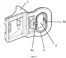
figure 3 représente une vue de dessous du dispositif de lafigure 2 . - La
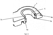
figure 4 représente une vue en coupe du dispositif de lafigure 2 . - La
figure 5 représente le dispositif de lafigure 2 dans lequel un élément de fixation (système vis-écrou) a été inséré dans l'orifice de la partie du dispositif. - La
figure 1 représente un dispositif destiné à être fixé 10 comprenant une partie 1 présentant un orifice 2 traversant formant une paroi interne 3 d'une hauteur h1 dans la partie 1. La paroi interne 3 comprend une protubérance 4a mobile selon l'axe X et une protubérance fixe 4b. - Le dispositif 10 comprend également un ruban métallique 5 ayant une hauteur h2 selon l'axe Z et une épaisseur. Le ruban métallique est de forme oblongue définissant deux surfaces planes 6a et deux demi-cercles 6b. Le ruban métallique 5 comprend deux paires d'encoches 7a et 7b disposées en regard l'une de l'autre sur les surfaces planes 6a, lesdites paires d'encoches 7a et 7b étant symétriques par rapport au plan (XY) orthogonal à l'axe Z. La présence de ces 4 encoches ayant une configuration particulière sur le ruban permet ainsi un assemblage très aisé du ruban dans l'orifice, et ce dans l'importe quel sens.
- Les protubérances 4a et 4b sont situées l'une en face de l'autre sur les deux surfaces planes et à deux positions différentes selon l'axe Z correspondant, avantageusement les plus éloignées possible.
- La protubérance 4a mobile permet l'insertion du ruban métallique dans l'orifice de la partie du dispositif 1.
- Comme illustré avec les
figures 2 et3 , une fois que le ruban métallique 5 est inséré dans l'orifice 2 de la partie du dispositif 1, ce dernier est accolé et fixé de manière durable à la partie du dispositif 1. En effet, la protubérance fixe 4b permet d'assurer le maintien du ruban 5 en jouant un rôle de butée contre une des encoches 7a. De plus, une fois que le ruban est inséré dans l'orifice et qu'une des encoches 7a coopère avec la protubérance fixe 4b, la protubérance mobile 4a retrouve sa position d'équilibre grâce à l'élasticité du matériau de la partie du dispositif 1. - Ainsi, comme représenté sur la
figure 4 , quand le ruban 5 est inséré dans l'orifice 2, ce dernier est fixé de manière solidaire à l'orifice de la partie du dispositif 1 puisque le ruban 5 est bloqué à la fois par la protubérance fixe 4b qui coopère avec l'encoche et par la protubérance mobile 4a revenu à sa position d'équilibre qui coopère avec l'encoche. - La
figure 5 représente le dispositif de lafigure 2 dans lequel un élément de fixation (ici un système vis 8-écrou 9- rondelle 12) est inséré dans l'orifice 2 de la partie du dispositif 1 afin de fixer ladite la partie du dispositif 1 à un support 11. - La présence du ruban métallique permet d'appliquer des couples de serrage important sur l'élément de fixation sans que l'orifice de la partie du dispositif soit déformé puisque l'élément de fixation est en contact uniquement avec le ruban métallique et non avec la partie du dispositif.
- De plus, la présence d'au moins une protubérance sur la paroi interne de l'orifice de la partie du dispositif et d'au moins un évidement sur le ruban métallique permet de fixer de manière solidaire le ruban à l'orifice de la partie du dispositif durant son transport et durant son installation.
Claims (9)
- Dispositif destiné à être fixé (10) incluant :- une partie (1) comprenant un orifice (2) traversant formant une paroi interne (3) dans ladite partie, ladite paroi interne (3) ayant une hauteur h1 selon un axe (Z); et- un ruban métallique (5), ayant une hauteur h2 selon l'axe (Z) et une épaisseur e, ledit ruban métallique (5) étant accolé et fixé à la paroi interne (3) de l'orifice (2);
caractérisé en ce que :• l'orifice (2) définit deux surfaces opposées dans la paroi interne (3),• la paroi interne (3) de l'orifice (2) comprend deux protubérances (4a, 4b) disposées sur les deux surfaces opposées et disposées à différentes positions z1, z2, avec z1 différent de z2, selon l'axe (Z),• le ruban métallique (5) comprend: un premier ensemble de deux encoches (7a, 7b) coopérant avec les protubérances (4a, 4b) de ladite paroi interne (3); et un second ensemble de deux encoches symétrique par rapport au premier ensemble dans un plan (XY) orthogonal à l'axe (Z), le ruban métallique (5) comprenant ainsi quatre encoches (7a, 7B),• au moins une protubérance (4a) est mobile dans la direction de l'axe (Z) et/ou dans un plan (XY) orthogonal à l'axe (Z) afin de permettre l'introduction du ruban métallique (5) dans l'orifice (22). - Dispositif destiné à être fixé (10) selon la revendication précédente caractérisé en ce que le ruban métallique (5) dépasse de la partie du dispositif (1) dans la direction Z.
- Dispositif destiné à être fixé (10) selon l'une des revendications précédentes, caractérisé en ce que l'orifice de la partie du dispositif (1) est de forme oblongue définissant deux surfaces planes opposées et deux surfaces courbes opposées dans la paroi interne (3).
- Dispositif destiné à être fixé (10) selon l'une des revendications précédentes caractérisé en ce que h2>h1.
- Dispositif destiné à être fixé (10) selon l'une des revendications précédentes caractérisé en ce que la partie du dispositif (1) est réalisée dans un matériau choisi dans le groupe consistant en un plastique, un composite et leurs mélanges.
- Dispositif destiné à être fixé (10) selon l'une des revendications précédentes caractérisé en ce que le ruban métallique (5) est réalisé en acier.
- Kit comprenant le dispositif destiné à être fixé tel que défini dans l'une des revendications précédentes et un élément de fixation.
- Procédé de fixation d'un dispositif sur un support (11) comprenant les étapes consistant à :fournir un dispositif destiné à être fixé (10) comportant une partie (1) comprenant un orifice (2) formant une paroi interne (3) d'une hauteur h1 selon un axe (Z) dans ladite partie; la paroi interne (3) de l'orifice (2) définissant deux surfaces opposées et comprenant deux protubérances (4a, 4b) disposées sur les deux surfaces opposées et disposées à différentes positions z1, z2, avec z1 différent de z2, selon l'axe (Z), au moins une protubérance (4a, 4b) étant mobile dans la direction de l'axe (Z) et/ou dans un plan (XY) orthogonal à l'axe (Z);fournir un ruban métallique (5) d'une hauteur h2 selon l'axe (Z) et d'une épaisseur e comprenant: un premier ensemble de deux encoches (7a, 7b) destiné à venir coopérer avec les protubérances (4a, 4b) de la paroi interne (3) de l'orifice (2); et un second ensemble de deux encoches symétrique par rapport au premier ensemble dans un plan (XY) orthogonal à l'axe (Z), le ruban métallique (5) comprenant ainsi quatre encoches (7a, 7B);fixer le ruban (5) dans l'orifice (2) de la partie du dispositif (1) en faisant coopérer les encoches (7a, 7b) du ruban (5) avec les protubérances (4a, 4b) de la paroi interne (3) de l'orifice (2), la protubérance mobile (4a) étant mise en déplacement en appliquant une force extérieure sur ladite protubérance (4a) ou sur un actuateur relié à ladite protubérance (4a) dans la direction de l'axe (Z) et/ou dans le plan (XY) orthogonal à l'axe (Z);disposer le dispositif obtenu à l'étape précédente sur un support ;insérer un élément de fixation (8, 9, 12) dans l'orifice (2) de la partie du dispositif (1); etfixer ledit dispositif au support (11).
- Utilisation du dispositif tel que défini dans l'une des revendications 1 à 6 ou du kit tel que défini dans la revendication 7 afin de fixer ledit dispositif à un support.
Applications Claiming Priority (1)
| Application Number | Priority Date | Filing Date | Title |
|---|---|---|---|
| FR1552135A FR3033848B1 (fr) | 2015-03-16 | 2015-03-16 | Dispositif destine a etre fixe comprenant une partie avec un orifice et un ruban metallique fixe audit orifice |
Publications (2)
| Publication Number | Publication Date |
|---|---|
| EP3070343A1 EP3070343A1 (fr) | 2016-09-21 |
| EP3070343B1 true EP3070343B1 (fr) | 2021-05-12 |
Family
ID=53177642
Family Applications (1)
| Application Number | Title | Priority Date | Filing Date |
|---|---|---|---|
| EP16160256.0A Active EP3070343B1 (fr) | 2015-03-16 | 2016-03-15 | Dispositif destine a etre fixe comprenant une partie avec un orifice et un ruban metallique fixe audit orifice |
Country Status (2)
| Country | Link |
|---|---|
| EP (1) | EP3070343B1 (fr) |
| FR (1) | FR3033848B1 (fr) |
Cited By (1)
| Publication number | Priority date | Publication date | Assignee | Title |
|---|---|---|---|---|
| EP4230879A1 (fr) * | 2022-02-22 | 2023-08-23 | SIMAF CZ s.r.o. | Ensemble de liaison d'une pièce en matière plastique à une pièce de base |
Families Citing this family (2)
| Publication number | Priority date | Publication date | Assignee | Title |
|---|---|---|---|---|
| DE102019200340A1 (de) * | 2019-01-14 | 2020-07-16 | Mahle International Gmbh | Bauteil und Loslagereinrichtung |
| EP3904705B1 (fr) | 2020-05-01 | 2024-10-09 | HellermannTyton s.a.s. | Support pour insert et ensemble comprenant le support et l'insert |
Family Cites Families (4)
| Publication number | Priority date | Publication date | Assignee | Title |
|---|---|---|---|---|
| US20080304906A1 (en) * | 2007-06-11 | 2008-12-11 | Michael Henry Maj | Creep and Corrosion Mitigating Inserts for Bolted Joints |
| DE102009011547A1 (de) * | 2009-03-03 | 2010-09-09 | Bayerische Motoren Werke Aktiengesellschaft | Gleitelement und Verfahren zu dessen Herstellung |
| CN104321545A (zh) * | 2012-06-13 | 2015-01-28 | 迈进有限公司 | 嵌入套管及嵌入螺母 |
| DE202013000387U1 (de) * | 2013-01-16 | 2014-01-27 | Hellermanntyton Gmbh | ln einer Überkopfposition vormontierbare Befestigungsvorrichtung zur Schraubmontage |
-
2015
- 2015-03-16 FR FR1552135A patent/FR3033848B1/fr active Active
-
2016
- 2016-03-15 EP EP16160256.0A patent/EP3070343B1/fr active Active
Non-Patent Citations (1)
| Title |
|---|
| None * |
Cited By (1)
| Publication number | Priority date | Publication date | Assignee | Title |
|---|---|---|---|---|
| EP4230879A1 (fr) * | 2022-02-22 | 2023-08-23 | SIMAF CZ s.r.o. | Ensemble de liaison d'une pièce en matière plastique à une pièce de base |
Also Published As
| Publication number | Publication date |
|---|---|
| FR3033848B1 (fr) | 2017-11-24 |
| EP3070343A1 (fr) | 2016-09-21 |
| FR3033848A1 (fr) | 2016-09-23 |
Similar Documents
| Publication | Publication Date | Title |
|---|---|---|
| EP2318747B1 (fr) | Raccord en deux parties reliées par baïonnette, procédé de renforcement de la liaison de parties de corps d' un tel raccord | |
| EP2917969B1 (fr) | Dispositif de fixation d'une cosse de raccordement electrique sur un support | |
| EP0751305A1 (fr) | Dispositif pour la fixation d'un élément appartenant à un mécanisme d'essuie-glace sur la caisse d'un véhicule automobile | |
| FR2943856A1 (fr) | Dispositif de support pour harnais electrique a la traversee d'une structure | |
| EP1553661A1 (fr) | Dispositif de connexion électrique destiné à réaliser un point de métallisation, support muni d'un tel dispositif de connexion, et aéronef équipé d'un tel support | |
| EP3070343A1 (fr) | Dispositif destine a etre fixe comprenant une partie avec un orifice et un ruban metallique fixe audit orifice | |
| FR2734958A1 (fr) | Dispositif de fixation d'aimants sur culasse de stator ou de rotor de moteurs electriques | |
| FR2770880A1 (fr) | Ensemble pour le positionnement, le centrage et le maintien en service d'une piece mecanique | |
| FR2720866A1 (fr) | Dispositif serre-câbles formant raccord arrière pour connecteur. | |
| EP3638891B1 (fr) | Gicleur a vis captive | |
| FR3096336A1 (fr) | Procédé de fixation d’un couvercle sur un orifice d’un système de direction assistée | |
| EP1963688B1 (fr) | Agencement pour l'assemblage de deux pieces par vissage par l'intermediaire d'un ensemble vis-ecrou | |
| EP2456014B1 (fr) | Borne de connexion entre une machine électrique tournante d'un véhicule automobile et un câble du circuit électrique dudit véhicule | |
| FR2975453A1 (fr) | Assemblage mecanique du type a bouton-pression, et application a un appareillage electrique | |
| EP4351929B1 (fr) | Support ajustable pour la fixation de composants électroniques et/ou mécaniques sur un parebrise d'un véhicule | |
| EP1057552B1 (fr) | Ensemble d'une rotule et d'un triangle de suspension | |
| EP1588897B1 (fr) | Elément de fixation et véhicule correspondant | |
| FR3094049A1 (fr) | Rotule sphérique | |
| EP4416397B1 (fr) | Dispositif de fixation | |
| FR2687195A1 (fr) | Organe d'assemblage a tete fraisee, tel qu'un rivet, pour l'assemblage de pieces en materiau composite munies de revetements electriquement conducteurs, et structure obtenue par cet assemblage. | |
| FR3098872A1 (fr) | Tirant pour structure notamment en treillis | |
| FR3096840A1 (fr) | Dispositif et procédé de liaison mécanique et électrique de deux organes électriques de puissance | |
| FR3089592A1 (fr) | Systeme de fixation pour cable | |
| FR2775045A1 (fr) | Procede de montage d'un joint souple sur une piece et piece equipee d'un tel joint | |
| EP1457691A2 (fr) | Procédé d'assemblage d'une bielle sur un support et dispositif anti-vibratoire fabrique par ce procédé |
Legal Events
| Date | Code | Title | Description |
|---|---|---|---|
| PUAI | Public reference made under article 153(3) epc to a published international application that has entered the european phase |
Free format text: ORIGINAL CODE: 0009012 |
|
| AK | Designated contracting states |
Kind code of ref document: A1 Designated state(s): AL AT BE BG CH CY CZ DE DK EE ES FI FR GB GR HR HU IE IS IT LI LT LU LV MC MK MT NL NO PL PT RO RS SE SI SK SM TR |
|
| AX | Request for extension of the european patent |
Extension state: BA ME |
|
| STAA | Information on the status of an ep patent application or granted ep patent |
Free format text: STATUS: REQUEST FOR EXAMINATION WAS MADE |
|
| 17P | Request for examination filed |
Effective date: 20170321 |
|
| RBV | Designated contracting states (corrected) |
Designated state(s): AL AT BE BG CH CY CZ DE DK EE ES FI FR GB GR HR HU IE IS IT LI LT LU LV MC MK MT NL NO PL PT RO RS SE SI SK SM TR |
|
| STAA | Information on the status of an ep patent application or granted ep patent |
Free format text: STATUS: EXAMINATION IS IN PROGRESS |
|
| 17Q | First examination report despatched |
Effective date: 20181127 |
|
| GRAP | Despatch of communication of intention to grant a patent |
Free format text: ORIGINAL CODE: EPIDOSNIGR1 |
|
| STAA | Information on the status of an ep patent application or granted ep patent |
Free format text: STATUS: GRANT OF PATENT IS INTENDED |
|
| RIC1 | Information provided on ipc code assigned before grant |
Ipc: F16B 5/02 20060101AFI20201016BHEP Ipc: F16B 21/07 20060101ALN20201016BHEP Ipc: F16B 41/00 20060101ALI20201016BHEP |
|
| INTG | Intention to grant announced |
Effective date: 20201110 |
|
| GRAS | Grant fee paid |
Free format text: ORIGINAL CODE: EPIDOSNIGR3 |
|
| GRAA | (expected) grant |
Free format text: ORIGINAL CODE: 0009210 |
|
| STAA | Information on the status of an ep patent application or granted ep patent |
Free format text: STATUS: THE PATENT HAS BEEN GRANTED |
|
| AK | Designated contracting states |
Kind code of ref document: B1 Designated state(s): AL AT BE BG CH CY CZ DE DK EE ES FI FR GB GR HR HU IE IS IT LI LT LU LV MC MK MT NL NO PL PT RO RS SE SI SK SM TR |
|
| REG | Reference to a national code |
Ref country code: GB Ref legal event code: FG4D Free format text: NOT ENGLISH |
|
| REG | Reference to a national code |
Ref country code: CH Ref legal event code: EP |
|
| REG | Reference to a national code |
Ref country code: DE Ref legal event code: R096 Ref document number: 602016057676 Country of ref document: DE |
|
| REG | Reference to a national code |
Ref country code: IE Ref legal event code: FG4D Free format text: LANGUAGE OF EP DOCUMENT: FRENCH |
|
| REG | Reference to a national code |
Ref country code: AT Ref legal event code: REF Ref document number: 1392372 Country of ref document: AT Kind code of ref document: T Effective date: 20210615 |
|
| REG | Reference to a national code |
Ref country code: LT Ref legal event code: MG9D |
|
| REG | Reference to a national code |
Ref country code: AT Ref legal event code: MK05 Ref document number: 1392372 Country of ref document: AT Kind code of ref document: T Effective date: 20210512 |
|
| REG | Reference to a national code |
Ref country code: NL Ref legal event code: MP Effective date: 20210512 |
|
| PG25 | Lapsed in a contracting state [announced via postgrant information from national office to epo] |
Ref country code: FI Free format text: LAPSE BECAUSE OF FAILURE TO SUBMIT A TRANSLATION OF THE DESCRIPTION OR TO PAY THE FEE WITHIN THE PRESCRIBED TIME-LIMIT Effective date: 20210512 Ref country code: LT Free format text: LAPSE BECAUSE OF FAILURE TO SUBMIT A TRANSLATION OF THE DESCRIPTION OR TO PAY THE FEE WITHIN THE PRESCRIBED TIME-LIMIT Effective date: 20210512 Ref country code: AT Free format text: LAPSE BECAUSE OF FAILURE TO SUBMIT A TRANSLATION OF THE DESCRIPTION OR TO PAY THE FEE WITHIN THE PRESCRIBED TIME-LIMIT Effective date: 20210512 Ref country code: BG Free format text: LAPSE BECAUSE OF FAILURE TO SUBMIT A TRANSLATION OF THE DESCRIPTION OR TO PAY THE FEE WITHIN THE PRESCRIBED TIME-LIMIT Effective date: 20210812 Ref country code: HR Free format text: LAPSE BECAUSE OF FAILURE TO SUBMIT A TRANSLATION OF THE DESCRIPTION OR TO PAY THE FEE WITHIN THE PRESCRIBED TIME-LIMIT Effective date: 20210512 |
|
| PG25 | Lapsed in a contracting state [announced via postgrant information from national office to epo] |
Ref country code: GR Free format text: LAPSE BECAUSE OF FAILURE TO SUBMIT A TRANSLATION OF THE DESCRIPTION OR TO PAY THE FEE WITHIN THE PRESCRIBED TIME-LIMIT Effective date: 20210813 Ref country code: IS Free format text: LAPSE BECAUSE OF FAILURE TO SUBMIT A TRANSLATION OF THE DESCRIPTION OR TO PAY THE FEE WITHIN THE PRESCRIBED TIME-LIMIT Effective date: 20210912 Ref country code: LV Free format text: LAPSE BECAUSE OF FAILURE TO SUBMIT A TRANSLATION OF THE DESCRIPTION OR TO PAY THE FEE WITHIN THE PRESCRIBED TIME-LIMIT Effective date: 20210512 Ref country code: RS Free format text: LAPSE BECAUSE OF FAILURE TO SUBMIT A TRANSLATION OF THE DESCRIPTION OR TO PAY THE FEE WITHIN THE PRESCRIBED TIME-LIMIT Effective date: 20210512 Ref country code: SE Free format text: LAPSE BECAUSE OF FAILURE TO SUBMIT A TRANSLATION OF THE DESCRIPTION OR TO PAY THE FEE WITHIN THE PRESCRIBED TIME-LIMIT Effective date: 20210512 Ref country code: NO Free format text: LAPSE BECAUSE OF FAILURE TO SUBMIT A TRANSLATION OF THE DESCRIPTION OR TO PAY THE FEE WITHIN THE PRESCRIBED TIME-LIMIT Effective date: 20210812 Ref country code: PL Free format text: LAPSE BECAUSE OF FAILURE TO SUBMIT A TRANSLATION OF THE DESCRIPTION OR TO PAY THE FEE WITHIN THE PRESCRIBED TIME-LIMIT Effective date: 20210512 Ref country code: PT Free format text: LAPSE BECAUSE OF FAILURE TO SUBMIT A TRANSLATION OF THE DESCRIPTION OR TO PAY THE FEE WITHIN THE PRESCRIBED TIME-LIMIT Effective date: 20210913 Ref country code: ES Free format text: LAPSE BECAUSE OF FAILURE TO SUBMIT A TRANSLATION OF THE DESCRIPTION OR TO PAY THE FEE WITHIN THE PRESCRIBED TIME-LIMIT Effective date: 20210512 |
|
| PG25 | Lapsed in a contracting state [announced via postgrant information from national office to epo] |
Ref country code: NL Free format text: LAPSE BECAUSE OF FAILURE TO SUBMIT A TRANSLATION OF THE DESCRIPTION OR TO PAY THE FEE WITHIN THE PRESCRIBED TIME-LIMIT Effective date: 20210512 |
|
| PG25 | Lapsed in a contracting state [announced via postgrant information from national office to epo] |
Ref country code: SK Free format text: LAPSE BECAUSE OF FAILURE TO SUBMIT A TRANSLATION OF THE DESCRIPTION OR TO PAY THE FEE WITHIN THE PRESCRIBED TIME-LIMIT Effective date: 20210512 Ref country code: SM Free format text: LAPSE BECAUSE OF FAILURE TO SUBMIT A TRANSLATION OF THE DESCRIPTION OR TO PAY THE FEE WITHIN THE PRESCRIBED TIME-LIMIT Effective date: 20210512 Ref country code: DK Free format text: LAPSE BECAUSE OF FAILURE TO SUBMIT A TRANSLATION OF THE DESCRIPTION OR TO PAY THE FEE WITHIN THE PRESCRIBED TIME-LIMIT Effective date: 20210512 Ref country code: CZ Free format text: LAPSE BECAUSE OF FAILURE TO SUBMIT A TRANSLATION OF THE DESCRIPTION OR TO PAY THE FEE WITHIN THE PRESCRIBED TIME-LIMIT Effective date: 20210512 Ref country code: EE Free format text: LAPSE BECAUSE OF FAILURE TO SUBMIT A TRANSLATION OF THE DESCRIPTION OR TO PAY THE FEE WITHIN THE PRESCRIBED TIME-LIMIT Effective date: 20210512 Ref country code: RO Free format text: LAPSE BECAUSE OF FAILURE TO SUBMIT A TRANSLATION OF THE DESCRIPTION OR TO PAY THE FEE WITHIN THE PRESCRIBED TIME-LIMIT Effective date: 20210512 |
|
| REG | Reference to a national code |
Ref country code: DE Ref legal event code: R097 Ref document number: 602016057676 Country of ref document: DE |
|
| PLBE | No opposition filed within time limit |
Free format text: ORIGINAL CODE: 0009261 |
|
| STAA | Information on the status of an ep patent application or granted ep patent |
Free format text: STATUS: NO OPPOSITION FILED WITHIN TIME LIMIT |
|
| 26N | No opposition filed |
Effective date: 20220215 |
|
| PG25 | Lapsed in a contracting state [announced via postgrant information from national office to epo] |
Ref country code: IS Free format text: LAPSE BECAUSE OF FAILURE TO SUBMIT A TRANSLATION OF THE DESCRIPTION OR TO PAY THE FEE WITHIN THE PRESCRIBED TIME-LIMIT Effective date: 20210912 Ref country code: AL Free format text: LAPSE BECAUSE OF FAILURE TO SUBMIT A TRANSLATION OF THE DESCRIPTION OR TO PAY THE FEE WITHIN THE PRESCRIBED TIME-LIMIT Effective date: 20210512 |
|
| PG25 | Lapsed in a contracting state [announced via postgrant information from national office to epo] |
Ref country code: IT Free format text: LAPSE BECAUSE OF FAILURE TO SUBMIT A TRANSLATION OF THE DESCRIPTION OR TO PAY THE FEE WITHIN THE PRESCRIBED TIME-LIMIT Effective date: 20210512 |
|
| PG25 | Lapsed in a contracting state [announced via postgrant information from national office to epo] |
Ref country code: MC Free format text: LAPSE BECAUSE OF FAILURE TO SUBMIT A TRANSLATION OF THE DESCRIPTION OR TO PAY THE FEE WITHIN THE PRESCRIBED TIME-LIMIT Effective date: 20210512 |
|
| REG | Reference to a national code |
Ref country code: CH Ref legal event code: PL |
|
| REG | Reference to a national code |
Ref country code: BE Ref legal event code: MM Effective date: 20220331 |
|
| PG25 | Lapsed in a contracting state [announced via postgrant information from national office to epo] |
Ref country code: LU Free format text: LAPSE BECAUSE OF NON-PAYMENT OF DUE FEES Effective date: 20220315 Ref country code: LI Free format text: LAPSE BECAUSE OF NON-PAYMENT OF DUE FEES Effective date: 20220331 Ref country code: IE Free format text: LAPSE BECAUSE OF NON-PAYMENT OF DUE FEES Effective date: 20220315 Ref country code: CH Free format text: LAPSE BECAUSE OF NON-PAYMENT OF DUE FEES Effective date: 20220331 |
|
| PG25 | Lapsed in a contracting state [announced via postgrant information from national office to epo] |
Ref country code: BE Free format text: LAPSE BECAUSE OF NON-PAYMENT OF DUE FEES Effective date: 20220331 |
|
| P01 | Opt-out of the competence of the unified patent court (upc) registered |
Effective date: 20230424 |
|
| PG25 | Lapsed in a contracting state [announced via postgrant information from national office to epo] |
Ref country code: HU Free format text: LAPSE BECAUSE OF FAILURE TO SUBMIT A TRANSLATION OF THE DESCRIPTION OR TO PAY THE FEE WITHIN THE PRESCRIBED TIME-LIMIT; INVALID AB INITIO Effective date: 20160315 |
|
| PG25 | Lapsed in a contracting state [announced via postgrant information from national office to epo] |
Ref country code: MK Free format text: LAPSE BECAUSE OF FAILURE TO SUBMIT A TRANSLATION OF THE DESCRIPTION OR TO PAY THE FEE WITHIN THE PRESCRIBED TIME-LIMIT Effective date: 20210512 Ref country code: CY Free format text: LAPSE BECAUSE OF FAILURE TO SUBMIT A TRANSLATION OF THE DESCRIPTION OR TO PAY THE FEE WITHIN THE PRESCRIBED TIME-LIMIT Effective date: 20210512 |
|
| PG25 | Lapsed in a contracting state [announced via postgrant information from national office to epo] |
Ref country code: MT Free format text: LAPSE BECAUSE OF FAILURE TO SUBMIT A TRANSLATION OF THE DESCRIPTION OR TO PAY THE FEE WITHIN THE PRESCRIBED TIME-LIMIT Effective date: 20210512 |
|
| PG25 | Lapsed in a contracting state [announced via postgrant information from national office to epo] |
Ref country code: TR Free format text: LAPSE BECAUSE OF FAILURE TO SUBMIT A TRANSLATION OF THE DESCRIPTION OR TO PAY THE FEE WITHIN THE PRESCRIBED TIME-LIMIT Effective date: 20210512 |
|
| PGFP | Annual fee paid to national office [announced via postgrant information from national office to epo] |
Ref country code: GB Payment date: 20260204 Year of fee payment: 11 |
|
| PGFP | Annual fee paid to national office [announced via postgrant information from national office to epo] |
Ref country code: DE Payment date: 20260223 Year of fee payment: 11 |
|
| PGFP | Annual fee paid to national office [announced via postgrant information from national office to epo] |
Ref country code: FR Payment date: 20260205 Year of fee payment: 11 |