EP3070342A1 - Fluidzylinder - Google Patents
Fluidzylinder Download PDFInfo
- Publication number
- EP3070342A1 EP3070342A1 EP16159795.0A EP16159795A EP3070342A1 EP 3070342 A1 EP3070342 A1 EP 3070342A1 EP 16159795 A EP16159795 A EP 16159795A EP 3070342 A1 EP3070342 A1 EP 3070342A1
- Authority
- EP
- European Patent Office
- Prior art keywords
- sensor elements
- optoelectronic sensor
- fluid cylinder
- marks
- output signal
- Prior art date
- Legal status (The legal status is an assumption and is not a legal conclusion. Google has not performed a legal analysis and makes no representation as to the accuracy of the status listed.)
- Granted
Links
Images


Classifications
-
- F—MECHANICAL ENGINEERING; LIGHTING; HEATING; WEAPONS; BLASTING
- F15—FLUID-PRESSURE ACTUATORS; HYDRAULICS OR PNEUMATICS IN GENERAL
- F15B—SYSTEMS ACTING BY MEANS OF FLUIDS IN GENERAL; FLUID-PRESSURE ACTUATORS, e.g. SERVOMOTORS; DETAILS OF FLUID-PRESSURE SYSTEMS, NOT OTHERWISE PROVIDED FOR
- F15B15/00—Fluid-actuated devices for displacing a member from one position to another; Gearing associated therewith
- F15B15/20—Other details, e.g. assembly with regulating devices
- F15B15/28—Means for indicating the position, e.g. end of stroke
- F15B15/2815—Position sensing, i.e. means for continuous measurement of position, e.g. LVDT
- F15B15/2846—Position sensing, i.e. means for continuous measurement of position, e.g. LVDT using detection of markings, e.g. markings on the piston rod
-
- F—MECHANICAL ENGINEERING; LIGHTING; HEATING; WEAPONS; BLASTING
- F15—FLUID-PRESSURE ACTUATORS; HYDRAULICS OR PNEUMATICS IN GENERAL
- F15B—SYSTEMS ACTING BY MEANS OF FLUIDS IN GENERAL; FLUID-PRESSURE ACTUATORS, e.g. SERVOMOTORS; DETAILS OF FLUID-PRESSURE SYSTEMS, NOT OTHERWISE PROVIDED FOR
- F15B15/00—Fluid-actuated devices for displacing a member from one position to another; Gearing associated therewith
- F15B15/08—Characterised by the construction of the motor unit
- F15B15/14—Characterised by the construction of the motor unit of the straight-cylinder type
- F15B15/1423—Component parts; Constructional details
-
- F—MECHANICAL ENGINEERING; LIGHTING; HEATING; WEAPONS; BLASTING
- F15—FLUID-PRESSURE ACTUATORS; HYDRAULICS OR PNEUMATICS IN GENERAL
- F15B—SYSTEMS ACTING BY MEANS OF FLUIDS IN GENERAL; FLUID-PRESSURE ACTUATORS, e.g. SERVOMOTORS; DETAILS OF FLUID-PRESSURE SYSTEMS, NOT OTHERWISE PROVIDED FOR
- F15B15/00—Fluid-actuated devices for displacing a member from one position to another; Gearing associated therewith
- F15B15/20—Other details, e.g. assembly with regulating devices
- F15B15/28—Means for indicating the position, e.g. end of stroke
- F15B15/2815—Position sensing, i.e. means for continuous measurement of position, e.g. LVDT
- F15B15/2869—Position sensing, i.e. means for continuous measurement of position, e.g. LVDT using electromagnetic radiation, e.g. radar or microwaves
- F15B15/2876—Position sensing, i.e. means for continuous measurement of position, e.g. LVDT using electromagnetic radiation, e.g. radar or microwaves using optical means, e.g. laser
-
- G—PHYSICS
- G01—MEASURING; TESTING
- G01B—MEASURING LENGTH, THICKNESS OR SIMILAR LINEAR DIMENSIONS; MEASURING ANGLES; MEASURING AREAS; MEASURING IRREGULARITIES OF SURFACES OR CONTOURS
- G01B11/00—Measuring arrangements characterised by the use of optical techniques
- G01B11/02—Measuring arrangements characterised by the use of optical techniques for measuring length, width or thickness
- G01B11/024—Measuring arrangements characterised by the use of optical techniques for measuring length, width or thickness by means of diode-array scanning
-
- G—PHYSICS
- G01—MEASURING; TESTING
- G01D—MEASURING NOT SPECIALLY ADAPTED FOR A SPECIFIC VARIABLE; ARRANGEMENTS FOR MEASURING TWO OR MORE VARIABLES NOT COVERED IN A SINGLE OTHER SUBCLASS; TARIFF METERING APPARATUS; MEASURING OR TESTING NOT OTHERWISE PROVIDED FOR
- G01D5/00—Mechanical means for transferring the output of a sensing member; Means for converting the output of a sensing member to another variable where the form or nature of the sensing member does not constrain the means for converting; Transducers not specially adapted for a specific variable
- G01D5/12—Mechanical means for transferring the output of a sensing member; Means for converting the output of a sensing member to another variable where the form or nature of the sensing member does not constrain the means for converting; Transducers not specially adapted for a specific variable using electric or magnetic means
- G01D5/244—Mechanical means for transferring the output of a sensing member; Means for converting the output of a sensing member to another variable where the form or nature of the sensing member does not constrain the means for converting; Transducers not specially adapted for a specific variable using electric or magnetic means influencing characteristics of pulses or pulse trains; generating pulses or pulse trains
- G01D5/24457—Failure detection
-
- G—PHYSICS
- G01—MEASURING; TESTING
- G01D—MEASURING NOT SPECIALLY ADAPTED FOR A SPECIFIC VARIABLE; ARRANGEMENTS FOR MEASURING TWO OR MORE VARIABLES NOT COVERED IN A SINGLE OTHER SUBCLASS; TARIFF METERING APPARATUS; MEASURING OR TESTING NOT OTHERWISE PROVIDED FOR
- G01D5/00—Mechanical means for transferring the output of a sensing member; Means for converting the output of a sensing member to another variable where the form or nature of the sensing member does not constrain the means for converting; Transducers not specially adapted for a specific variable
- G01D5/12—Mechanical means for transferring the output of a sensing member; Means for converting the output of a sensing member to another variable where the form or nature of the sensing member does not constrain the means for converting; Transducers not specially adapted for a specific variable using electric or magnetic means
- G01D5/244—Mechanical means for transferring the output of a sensing member; Means for converting the output of a sensing member to another variable where the form or nature of the sensing member does not constrain the means for converting; Transducers not specially adapted for a specific variable using electric or magnetic means influencing characteristics of pulses or pulse trains; generating pulses or pulse trains
- G01D5/245—Mechanical means for transferring the output of a sensing member; Means for converting the output of a sensing member to another variable where the form or nature of the sensing member does not constrain the means for converting; Transducers not specially adapted for a specific variable using electric or magnetic means influencing characteristics of pulses or pulse trains; generating pulses or pulse trains using a variable number of pulses in a train
- G01D5/2454—Encoders incorporating incremental and absolute signals
- G01D5/2455—Encoders incorporating incremental and absolute signals with incremental and absolute tracks on the same encoder
- G01D5/2457—Incremental encoders having reference marks
-
- F—MECHANICAL ENGINEERING; LIGHTING; HEATING; WEAPONS; BLASTING
- F15—FLUID-PRESSURE ACTUATORS; HYDRAULICS OR PNEUMATICS IN GENERAL
- F15B—SYSTEMS ACTING BY MEANS OF FLUIDS IN GENERAL; FLUID-PRESSURE ACTUATORS, e.g. SERVOMOTORS; DETAILS OF FLUID-PRESSURE SYSTEMS, NOT OTHERWISE PROVIDED FOR
- F15B2215/00—Fluid-actuated devices for displacing a member from one position to another
- F15B2215/30—Constructional details thereof
Definitions
- the present invention relates to a fluid cylinder with a guided in a cylinder jacket piston rod, on which a mark is provided with equidistantly arranged way marks.
- the marking is directed to an optical sensor unit. With the aid of the optical sensor unit, a stroke length and / or a stroke speed of the fluid cylinder can be detected.
- a hybrid-cylinder optical position sensor serves as a position monitoring system which detects the position of a movable member relative to a stationary sensor circuit.
- the sensor circuit determines the current position by an image evaluation, in which the movement is determined by the comparison of two consecutively recorded images.
- WO 96/35098 a device for position measurement for cylinder drives is known.
- the moving piston rod is used as a displacement measuring system in which a bar pattern is produced on the piston rod only by the action of laser radiation.
- a sensor based on optical reflection detects the dark lines and the light gaps and can thereby hold the position of the piston rod.
- a measuring and control device for a lift has become known, in which a plurality of way marks are mounted on a movable body and a directed to the way mark sensor detects the way marks and counted up an evaluation device, the number of way marks and so a distance is determined.
- a truck with a hydraulic cylinder has become known, which has a piston rod and a cylinder jacket, in the piston rod is guided.
- an optical sensor is provided which has a light source directed toward the piston rod and a receiver for the reflected light. The optical sensor detects movement of the piston rod relative to the sensor from the light reflected in succession to the receiver.
- a position measuring device in which the position of two objects is measured relative to each other.
- a coded strip is attached to the one object which has a pseudorandom binary sequence.
- a detection device is directed to this sequence and detects it at several points at the same time in order to be able to determine a relative movement.
- EP 1 426 737 B1 is a Positionsmesseicardi for a cylinder has become known in which way marks are applied to a piston rod with different distances. The position of the landmarks is detected by an optical sensor.
- a stroke position scale has been disclosed wherein the strokes have first and second edges of which either the first or second edge is arranged at regular intervals.
- the strokes have two different widths and several consecutive strokes thus form an individual binary code for indicating the position of the strokes on the scale.
- a position measuring device for fluid cylinders has become known in which an image sensor detects a rectangular measuring section and a code pattern is mounted on a piston rod which can be detected.
- EP 1 461 585 B1 For example, a cylinder with an optical detection device is known. Fiber optic sensor arrays are evenly spaced with a quarter phase shift from an incremental mark so that changes do not occur simultaneously. From the sequence of changes occurring, the direction of movement and the position of a piston rod relative to a starting point are determined.
- EP 2 222 966 B1 For example, a system for determining the position of a piston along its stroke for a fluid dynamic actuator is known. On the piston rod grooves are provided, which can be detected optically for position detection.
- the invention has for its object to provide a fluid cylinder, which can detect the position of its piston rod in a simple and reliable manner.
- the fluid cylinder according to the invention has a guided in a cylinder jacket piston rod to which a mark is provided with equidistantly arranged marks. Furthermore, the fluid cylinder has an optical sensor unit directed at the marking. According to the invention, the sensor unit has two or more optoelectronic sensor elements arranged equidistant from each other. The optoelectronic sensor elements each generate a binary output signal corresponding to the mark on the piston rod. According to the invention, the optoelectronic sensors are arranged relative to the marks in the axial direction such that each binary output signal has a predetermined phase shift to the temporally subsequent output signal.
- phase shift of the output signals relative to one another allows a good spatial resolution of the sensor unit and makes it possible to reliably detect the position or the temporal change of the position.
- the position detection can be robust.
- three optoelectronic sensor elements are used.
- the marking also has at least one reference mark, in which all the optoelectronic sensor elements respond simultaneously.
- the sensor unit has an error detection unit which converts the applied binary output signals of the optoelectronic sensor elements into a Gray code and checks whether more than one bit has changed with a change of the output signals.
- the Gray code is a code known from information technology which, when using N optoelectronic sensor elements, also comprises N bits.
- the Gray code is constructed so that with increasing time and change of the signals of the optoelectronic sensor elements always only one bit changes. The Hamming distance of the Gray code is therefore equal to 1. Should the situation occur that more than one bit changes, two different cases can be distinguished.
- the error detection unit can deduce therefrom a measurement error on one of the optical sensor elements.
- a detected as faulty signal is registered. However, if all the optical sensor elements respond, then the error detection unit assumes that a reference mark and no erroneous signal has been detected.
- the marks each have at least one length in the axial direction of the piston rod, which corresponds to the distance of two adjacent marks. In the axial direction, therefore, the marking extends at least over the same length as the distance between two adjacent marks.
- the electronics of the sensor elements each generate an output signal with a duty cycle of 0.5.
- the duty cycle of 0.5 means that in the digital output signal state 1 is present for as long as the state zero.
- the predetermined phase shift between two temporally successive output signals is an integer fraction of a full period. This means that the digital output signal is again periodic even with the output signals of the other optoelectronic sensor elements.
- the integer fraction of the full period is equal to the number of optoelectronic sensor elements. This means that when using three optoelectronic sensor elements after three complete periods of a signal, the signal sequence is repeated.
- (N) is the number of sensor elements and (n) is a natural number.
- the distance (a) between the optoelectronic sensor elements is predetermined, for example, as the minimum distance of the optoelectronic sensor elements, without these interacting mutually. From this distance (t) between the marks then results in selected number (n) and the number (N) of the sensor elements, the distance (a) of the sensor elements.
- the distance (a) between the sensor elements is defined, for example, as a distance between their measuring axes.
- the markings have a predetermined extent in the circumferential direction and the optoelectronic sensor elements are arranged offset from one another in the circumferential direction.
- the radial distance of the optoelectronic sensor elements to the marking and the cylinder rod surface can vary. The relevant for the position detection axial distance between the optoelectronic sensor elements remains unchanged. The additional distance in the circumferential direction and / or in radial Direction does not contribute to the coding, but does increase the distance between the measuring ranges of the contrast light scanners.
- Fig. 1 shows a schematic view of a piston rod 10 with an applied mark 12, which is introduced by tempering discoloration by laser in the chromium layer.
- the marker 12 has at least one reference mark 14, which is characterized by a long continuous mark.
- the reference mark has a sufficient length to be detected simultaneously by all optoelectronic sensor elements.
- two sensor elements respond and in a second part separated from the first part, the third sensor element responds.
- all sensor elements must respond, regardless of whether the mark is formed on the piece or not.
- a plurality of reference marks can also be applied to the piston rod.
- the mark 16 adjoining the reference mark 14 in the axial direction consist of marks arranged equidistantly to one another, which are shown in black.
- a sensor unit 18 with three optoelectronic sensor elements 20a, 20b, 20c is shown schematically.
- the optoelectronic sensor elements 20a, 20b, 20c are designed as light-emitting diodes with a corresponding receiver.
- the receiver can be a photodiode or a phototransistor tuned to the LED. They receive a signal reflected from the piston rod, with the dark color of a mark correspondingly attenuating the signal proportionally. About threshold comparisons the applied signal is digitized, so that digitizing the signals have a duty cycle 0.5 of. In this case, a 1 is preferably shown digitally in the case of a dark and / or black mark.
- the optoelectronic sensor elements 20a, 20b, 20c in the axial direction one behind the other.
- the view from the top in Fig. 2b shows that the contrast light scanners 20a, 20b, 20c, however, can be distributed in the circumferential direction to each other. Due to the radial distribution of the geometric distance of the contrast sensor is increased to each other and a mutual influence between the contrast light sensors avoided.
- FIGS. 3 to 5 explain the signal processing and error detection for the example of three optoelectronic sensor elements.
- the sensor unit and the processing of the signals has to be made when (N) optoelectronic sensor elements are provided.
- N the number of optoelectronic sensor elements.
- the increase in the axial length of the sensor unit depends on how the optoelectronic sensor elements are distributed around the piston rod in the circumferential direction and how the sensor elements are constructed.
- Fig. 1 shows a sensor unit 18, in which the three optoelectronic sensor elements 20a, 20b, 20c each have the distance (a) from the measuring axis to the measuring axis. Since the optoelectronic sensor elements are always arranged equidistant from each other, the size (a) can always denote the distance between them.
- Fig. 4 shows the time course of the digital signals.
- the upper row shows, for example, the digital signal of the optoelectronic sensor element 20a
- the middle row shows the signal of the optoelectronic sensor element 20b
- the lower row shows the signal of the optoelectronic sensor element 20c.
- Fig. 5 shows the path detected on the basis of the signals of the optoelectronic sensor elements, which the mark has traversed relative to the sensor unit.
- Fig. 5 shows a made by the sensor unit 18 Gray coding.
- the signals of the optoelectronic sensor elements 20a, 20b, 20c are each combined into a triple. Since the marking moves past the sensor unit during the measurement process and the resulting output signals have a phase shift relative to one another, the situation naturally arises that only one bit can ever change in the event of a state change. This means that the state change of the Gray coding always takes place along the edges of the hexagon.
- the triple is [111] and the mark is unambiguously identified as the reference mark.
- the triple [000] can not occur.
- a change occurs by more than 1 bit, the signal is faulty. Faulty signals are registered and a corresponding status message is generated. Preferably, an error is output or the measurement is repeated.
- the reference mark can also be achieved by changing only one bit, for example [011] -> [111], [101] -> [111] and [110] -> [111]. Therefore, the reference mark is not determined by changing the bit, but is determined by its value [111].
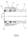
- Fig. 6 shows a section through a cylinder head 22 in which a piston rod 10 is guided.
- the cylinder head 22 has a seal 24 in the form of a U-ring and a scraper 26.
- a cap 28 is mounted, which has a cavity 30 for the sensor unit, which can be mounted from the outside.
- the cap 28 has at its end facing away from the cylinder head, a further scraper 32.
- the cap is constructed so that a superposition of marker 12 and sensor unit 18 is set and then the cap can be secured against rotation on the cylinder head.
Landscapes
- Physics & Mathematics (AREA)
- Engineering & Computer Science (AREA)
- Fluid Mechanics (AREA)
- Mechanical Engineering (AREA)
- General Engineering & Computer Science (AREA)
- General Physics & Mathematics (AREA)
- Optics & Photonics (AREA)
- Health & Medical Sciences (AREA)
- Electromagnetism (AREA)
- Radar, Positioning & Navigation (AREA)
- Remote Sensing (AREA)
- Toxicology (AREA)
- Actuator (AREA)
- Length Measuring Devices With Unspecified Measuring Means (AREA)
- Length Measuring Devices By Optical Means (AREA)
Abstract
Description
- Die vorliegende Erfindung betrifft einen Fluidzylinder mit einer in einem Zylindermantel geführten Kolbenstange, an der eine Markierung mit äquidistant angeordneten Wegmarken vorgesehen ist. Auf die Markierung ist eine optische Sensoreinheit gerichtet. Mit Hilfe der optischen Sensoreinheit kann eine Hublänge und/oder eine Hubgeschwindigkeit des Fluidzylinders erfasst werden.
- Aus
DE 10 2005 059 251 ist ein optischer Hybrid-Zylinderpositionssensor bekannt. Der Sensor dient als ein Lageüberwachungssystem, das die Lage eines bewegbaren Gliedes gegenüber einer ortsfesten Sensorschaltung erfasst. Die Sensorschaltung ermittelt die aktuelle Position durch eine Bildauswertung, bei der die Bewegung durch den Vergleich von zwei nacheinander aufgenommenen Bildern ermittelt wird. - Aus
WO 96/35098 - Aus
DE 102 42 630 A1 ist eine Mess- und Steuervorrichtung für eine Hebebühne bekannt geworden, bei der an einem beweglichen Körper mehrere Wegmarken angebracht sind und ein auf die Wegmarken gerichteter Sensor die Wegmarken detektiert und über eine Auswertevorrichtung die Anzahl der Wegmarken hochgezählt und so ein Abstand bestimmt wird. - Aus
DE 10 2010 044 656 A1 ist ein Flurförderzeug mit einem Hydraulikzylinder bekannt geworden, der eine Kolbenstange und einen Zylindermantel aufweist, in dem die Kolbenstange geführt ist. In einem Kopfbereich ist ein optischer Sensor vorgesehen, der eine auf die Kolbenstange gerichtete Lichtquelle und einen Empfänger für das reflektierte Licht aufweist. Der optische Sensor erfasst aus dem zeitlich nacheinander zu dem Empfänger reflektierten Licht eine Bewegung der Kolbenstange relativ zu dem Sensor. - Aus
WO 84/01027 - Aus
EP 1 426 737 B1 ist eine Positionsmesseirichtung für einen Zylinder bekannt geworden, bei dem Wegmarken auf einer Kolbenstange mit unterschiedlichen Abständen aufgebracht sind. Die Position der Wegmarken wird über einen optischen Sensor erfasst. - Aus
DE 693 07 135 T2 ist eine Positionsskala mit Strichen bekannt geworden, wobei die Striche eine erste und eine zweite Kante aufweisen, von denen entweder die erste oder die zweite Kante in regelmäßigen Abschnitten angeordnet ist. Die Striche besitzen zwei verschiedene Breiten und mehrere aufeinander folgende Striche bilden somit einen individuellen binären Code zur Anzeige der Lage der Striche auf der Skala. - Aus
AT 511 883 - Aus
WO 2009/112895 A1 ist eine Positionsmesseinrichtung bekannt geworden, bei der mit einem optischen Photosensor eine Veränderung an der Kolbenstange mit unterschiedlichen Markierungen erfasst wird. - Aus
EP 1 461 585 B1 ist ein Zylinder mit einer optischen Erfassungseinrichtung bekannt. Faseroptische Sensorfelder sind gleichmäßig beabstandet mit einer Viertelphasenverschiebung gegenüber einer inkrementellen Markierung angeordnet, so dass Änderungen nicht gleichzeitig auftreten. Aus der Reihenfolge der auftretenden Änderungen werden die Bewegungsrichtung und die Position einer Kolbenstange relativ zu einem Startpunkt bestimmt. - Aus
EP 2 222 966 B1 ist ein System zur Bestimmung der Position eines Kolbens entlang seinem Hubweg für einen fluiddynamischen Aktuator bekannt. Auf der Kolbenstange sind Rillen vorgesehen, die optisch zur Positionserfassung detektiert werden können. - Aus
US 2013/0076346 A1 ist ein System und ein Verfahren zur Bestimmung einer Relativposition bekannt. Hierzu ist ein Feld von Codewörtern vorgesehen, in denen jeweils die Position ihrer Anbringung codiert ist. - Der Erfindung liegt die Aufgabe zugrunde, einen Fluidzylinder bereitzustellen, der auf einfache und zuverlässige Art und Weise die Position seiner Kolbenstange erfassen kann.
- Erfindungsgemäß wird die Aufgabe durch einen Fluidzylinder mit den Merkmalen aus Anspruch 1 gelöst. Vorteilhafte Ausgestaltungen bilden den Gegenstand der Unteransprüche.
- Der erfindungsgemäße Fluidzylinder besitzt eine in einem Zylindermantel geführte Kolbenstange, an der eine Markierung mit äquidistant angeordneten Marken vorgesehen ist. Ferner besitzt der Fluidzylinder eine auf die Markierung gerichtete optische Sensoreinheit. Erfindungsgemäß weist die Sensoreinheit zwei oder mehr äquidistant zueinander angeordnete optoelektronische Sensorelemente auf. Die optoelektronische Sensorelemente erzeugen jeweils ein binäres Ausgangssignal entsprechend der Markierung auf der Kolbenstange. Erfindungsgemäß sind die optoelektronischen Sensoren relativ zu den Marken in axialer Richtung derart angeordnet, dass jedes binäre Ausgangssignal eine vorbestimmte Phasenverschiebung zu dem zeitlich nachfolgenden Ausgangssignal besitzt. Die Phasenverschiebung der Ausgangssignale relativ zueinander erlaubt eine gute Ortsauflösung der Sensoreinheit und gestattet es, die Position bzw. die zeitliche Veränderung der Position zuverlässig zu erfassen. Durch die Verwendung von zwei oder mehr als zwei optoelektronischen Sensorelementen kann die Positionserfassung robust erfolgen. Bevorzugt werden drei optoelektronische Sensorelemente verwendet.
- Erfindungsgemäß weist die Markierung auch mindestens eine Referenzmarke auf, bei der sämtliche optoelektronischen Sensorelemente gleichzeitig ansprechen. Die Sensoreinheit besitzt eine Fehlererkennungseinheit, die die anliegenden binären Ausgangssignale der optoelektronischen Sensorelemente in einen Gray-Code umwandelt und prüft, ob sich mehr als ein Bit bei einer Änderung der Ausgangssignale verändert hat. Bei dem Gray-Code handelt es sich um einen an sich bekannten Code aus der Informationstechnik, der bei der Verwendung von N optoelektronischen Sensorelementen auch N-Bit umfasst. Der Gray-Code ist so aufgebaut, dass mit zunehmender Zeit und Veränderung der Signale der optoelektronischen Sensorelemente stets nur ein Bit sich ändert. Die Hamming-Distanz des Gray-Codes ist somit gleich 1. Sollte die Situation auftreten, dass sich mehr als ein Bit verändert, so können zwei unterschiedliche Fälle unterschieden werden. Die Fehlererkennungseinheit kann hieraus auf einen Messfehler an einem der optischen Sensorelemente schließen. In einer bevorzugten Ausgestaltung wird ein als fehlerhaft erkanntes Signal registriert. Wenn jedoch sämtliche optische Sensorelemente ansprechen, dann geht die Fehlererkennungseinheit davon aus, dass eine Referenzmarke und kein fehlerhaftes Signal detektiert wurde.
- In einer bevorzugten Ausgestaltung der Erfindung besitzen die Marken jeweils mindestens eine Länge in axialer Richtung der Kolbenstange, die dem Abstand von zwei benachbarten Marken entspricht. In axialer Richtung erstreckt sich die Markierung also mindestens über die gleiche Länge wie der Abstand zwischen zwei benachbarten Marken.
- In einer weiter bevorzugten Ausgestaltung erzeugt die Elektronik der Sensorelemente jeweils ein Ausgangssignal mit einem Tastgrad von 0,5. Der Tastgrad von 0,5 bedeutet, dass in dem digitalen Ausgangssignal der Zustand 1 genauso lange wie der Zustand Null anliegt. Durch das Einstellen des optoelektronischen Sensorelements mit seinem Schwellwert bei der Hell-Dunkel-Erkennung kann zusammen mit der geeigneten Ausdehnung in axialer Richtung der Marken der Tastgrad von 0,5 erreicht werden.
- In einer bevorzugten Ausgestaltung ist die vorbestimmte Phasenverschiebung zwischen zwei zeitlich aufeinander folgenden Ausgangssignalen ein ganzzahliger Bruchteil einer vollen Periode. Dies bedeutet, dass das digitale Ausgangssignal selbst mit den Ausgangssignalen der anderen optoelektronischen Sensorelemente wieder periodisch ist.
- In einer bevorzugten Ausgestaltung ist der ganzzahlige Bruchteil der vollen Periode gleich der Anzahl der optoelektronischen Sensorelemente. Dies bedeutet, dass bei der Verwendung von drei optoelektronischen Sensorelementen nach drei vollständigen Perioden eines Signals, sich die Signalfolge wiederholt.
- In einer bevorzugten Ausgestaltung genügt der Abstand (a) zwischen der Messachse der Sensorelemente und der Abstand (t) zwischen den Marken der folgenden Gleichung:

- In einer bevorzugten Weiterentwicklung besitzen die Markierungen eine vorbestimmte Ausdehnung in Umfangsrichtung und die optoelektronischen Sensorelemente sind in Umfangsrichtung versetzt zueinander angeordnet. Zudem kann der radiale Abstand der optoelektronischen Sensorelemente zur Markierung und der Zylinderstangenoberfläche variieren. Der für die Positionserkennung relevante axiale Abstand zwischen den optoelektronischen Sensorelementen bleibt dabei unverändert. Der zusätzliche Abstand in Umfangsrichtung und/oder in radialer Richtung trägt nicht zu der Codierung bei, vergrößert aber den Abstand zwischen den Messbereichen der Kontrastlichttaster.
- Die Erfindung wird nachfolgend an einem Ausführungsbeispiel näher erläutert. Es zeigen:
- Fig. 1
- eine schematische Ansicht der Kolbenstange mit ihrer Markierung und der darauf gerichteten optischen Sensoreinheit,
- Fign. 2a, b
- die relative Positionierung zwischen Markierung und Sensoreinheit in einer Ansicht von der Seite und in einer Ansicht von oben,
- Fig.3
- eine schematische Ansicht zu den axialen Abständen zwischen Markierung und Sensoreinheit,
- Fig. 4
- die zeitliche Abfolge der Signalfolge,
- Fig. 5
- eine Darstellung der Gray-Codierung und
- Fig. 6
- einen Schnitt durch den Zylindermantel in seinem Kopfabschnitt.
-
Fig. 1 zeigt in einer schematischen Ansicht eine Kolbenstange 10 mit einer aufgebrachten Markierung 12, die durch Anlassverfärbung per Laser in die Chromschicht eingebracht ist. Die Markierung 12 besitzt mindestens eine Referenzmarke 14, die sich durch eine lange durchgehende Marke auszeichnet. Die Referenzmarke besitzt eine ausreichende Länge, um von allen optoelektronischen Sensorelementen gleichzeitig detektiert zu werden. Alternativ ist es auch möglich, dass bei der Referenzmarke in einem ersten Teil zwei Sensorelemente ansprechen und in einem vom ersten Teil getrennten zweiten Teil das dritte Sensorelement anspricht. Um eine Marke als Referenzmarke zu qualifizieren, müssen alle Sensorelemente ansprechen, unabhängig davon, ob die Markierung am Stück ausgebildet ist oder nicht. Je nach Ausgestaltung können auch mehrere Referenzmarken auf die Kolbenstange aufgebracht werden. Die sich in axialer Richtung an die Referenzmarke 14 anschließenden Marke 16 bestehen aus äquidistant zueinander angeordneten Marken, die schwarz dargestellt sind. Eine Sensoreinheit 18 mit drei optoelektronischen Sensorelementen 20a, 20b, 20c ist schematisch dargestellt. - Die optoelektronischen Sensorelemente 20a, 20b, 20c sind als Leuchtdioden mit einem entsprechenden Empfänger ausgebildet. Als Empfänger kann eine auf die Leuchtdiode abgestimmte Fotodiode oder ein Fototransistor eingesetzt werden. Sie empfangen ein von der Kolbenstange reflektiertes Signal, wobei die dunkle Farbe einer Markierung das Signal entsprechend proportional abschwächt. Über Schwellwertvergleiche wird das anliegende Signal digitalisiert, so dass eine Digitalisierung die Signale einen Tastgrad 0,5 von aufweisen. Dabei wird bevorzugt bei einer dunklen und/oder schwarzen Marke digital eine 1 dargestellt.
- Wie in
Fig. 2a zu erkennen, liegen die optoelektronischen Sensorelemente20a, 20b, 20c in axialer Richtung hintereinander. Der Blick von oben inFig. 2b zeigt, dass die Kontrastlichttaster 20a, 20b, 20c jedoch in Umfangsrichtung zueinander verteilt liegen können. Durch die radiale Verteilung wird der geometrische Abstand der Kontrastlichttaster zueinander vergrößert und eine wechselseitige Beeinflussung zwischen den Kontrastlichttastern vermieden. -
Figuren 3 bis 5 erläutern die Signalverarbeitung und die Fehlererkennung für das Beispiel von drei optoelektronischen Sensorelementen. Bei der Erläuterung wird gelegentlich darauf verwiesen, wie die Sensoreinheit und die Verarbeitung der Signale zu erfolgen hat, wenn (N) optoelektronische Sensorelemente vorgesehen sind. Bei der Bestimmung der idealen Zahl von optoelektronischen Sensorelementen ist zu berücksichtigen, dass diese gewisse Anforderungen an die Ausdehnung der Sensoreinheit in axialer Richtung stellen, so dass mit einer größer werdenden Anzahl von optoelektronischen Sensorelementen die Sensoreinheit länger baut. Dabei hängt der Zuwachs an axialer Länge der Sensoreinheit davon ab, wie die optoelektronischen Sensorelemente in Umfangsrichtung um die Kolbenstange verteilt und wie die Sensorelemente aufgebaut sind. -
Fig. 1 zeigt eine Sensoreinheit 18, bei der die drei optoelektronischen Sensorelemente 20a, 20b, 20c jeweils von Messachse zu Messachse den Abstand (a) besitzen. Da die optoelektronischen Sensorelemente stets äquidistant zueinander angeordnet sind, kann die Größe (a) immer den Abstand zwischen diesen bezeichnen. -
Fig. 4 zeigt den zeitlichen Verlauf der Digitalsignale. Hierbei zeigt die obere Reihe beispielsweise das Digitalsignal des optoelektronischen Sensorelements 20a, die mittlere Reihe das Signal des optoelektronischen Sensorelements 20b und die untere Reihe das Signal des optoelektronischen Sensorelements 20c. Deutlich zu erkennen ist, dass zwischen den Signalen der optoelektronischen Sensorelemente 20a und 20b einen Phasenwinkel von 120° = 360°/3 herrscht. - Das untere Diagramm in
Fig. 5 zeigt den aufgrund der Signale der optoelektronischen Sensorelemente erfassten Weg, den die Markierung relativ zu der Sensoreinheit zurückgelegt hat. -
Fig. 5 zeigt eine von der Sensoreinheit 18 vorgenommene Gray-Codierung. Hierbei werden die Signale der optoelektronischen Sensorelemente 20a, 20b, 20c jeweils in einen Triple zusammengefasst. Da sich bei dem Messvorgang die Markierung an der Sensoreinheit vorbei bewegt und die dabei entstehenden Ausgangssignale eine Phasenverschiebung zueinander besitzen, tritt auf natürliche Weise die Situation auf, dass sich bei einer Zustandsänderung stets nur ein Bit ändern kann. Dies bedeutet, dass die Zustandsänderung der Gray-Codierung stets entlang der Kanten des Sechsecks erfolgt. Befinden sich drei Sensorelemente über einer Referenzmarke, also entweder über einer einheitlichen Referenzmarke für drei Sensorelemente oder über einer zweiteiligen Referenzmarke, ist das Triple [111] und die Marke wird eindeutig als Referenzmarke erkannt. Das Triple [000] kann nicht auftreten. Tritt eine Änderung um mehr als 1 Bit auf, so ist das Signal fehlerhaft. Fehlerhafte Signale werden registriert und eine entsprechende Statusmitteilung erzeugt. Bevorzugt wird ein Fehlerausgegeben oder die Messung wiederholt. - Wichtig für das Verständnis ist, dass die Referenzmarke auch durch Änderung nur eines Bits erreicht werden kann, also beispielsweise [011] -> [111], [101] -> [111] und [110] -> [111]. Daher wird die Referenzmarke nicht über die Änderung der Bit bestimmt, sondern ist durch ihren Wert [111] festgelegt.
-
Fig. 6 zeigt einen Schnitt durch einen Zylinderkopf 22, in dem eine Kolbenstange 10 geführt ist. Der Zylinderkopf 22 besitzt eine Dichtung 24 in Form eines Nutringes und einen Abstreifer 26. Auf das Ende des Zylinderkopfes 22 ist eine Kappe 28 aufgesetzt, die einen Hohlraum 30 für die Sensoreinheit besitzt, die von außen montiert werden kann. Die Kappe 28 besitzt an ihrem vom Zylinderkopf fortweisenden Ende einen weiteren Abstreifer 32. Die Kappe ist so konstruiert, dass eine Übereinander-Anordnung von Markierung 12 und Sensoreinheit 18 eingestellt werden und anschließend die Kappe verdrehsicher an dem Zylinderkopf befestigt werden kann. -
- 10
- Kolbenstange
- 12
- Markierung
- 14
- Referenzmarke
- 16
- Marke
- 18
- Sensoreinheit
- 20a-c
- optoelektronische Sensorelemente
- 22
- Zylinderkopf
- 24
- Dichtung
- 26
- Abstreifer
- 28
- Kappe
- 30
- Hohlraum
- 32
- Abstreifer
Claims (9)
- Fluidzylinder mit einer in einem Zylindermantel geführten Kolbenstange (10), an der eine Markierung (12) mit äquidistant angeordneten Marken vorgesehen ist und mit einer auf die Markierung gerichteten, optischen Sensoreinheit (18), die mehr als zwei äquidistant angeordnete optoelektronische Sensorelemente (20a, 20b, 20c) aufweist, mit denen jeweils ein binäres Ausgangssignal erzeugt werden kann, wobei der axiale Abstand zwischen den optoelektronischen Sensorelementen (20a, 20b, 20c) und den Marken derart bemessen ist, dass jedes binäre Ausgangssignal eine vorbestimmte Phasenverschiebung zu dem zeitlich nachfolgenden Ausgangssignal besitzt und die Markierung mindestens eine Referenzmarke aufweist, bei der für sämtliche optoelektronische Sensorelemente ein Ausgangssignal vorliegt,
dadurch gekennzeichnet, dass
die Sensoreinheit (18) eine Fehlererkennung besitzt, die die anliegenden binären Ausgangssignale der optoelektronischen Sensorelemente (20a, 20b, 20c) in einen Gray-Code umwandelt und bei einer Änderung der Ausgangssignale um mehr als ein Bit ein fehlerhaftes Signal erkennt und ebenfalls bei Ansprechen sämtlicher Sensorelemente die mindestens eine Referenzmarke erkennt. - Fluidzylinder nach Anspruch 1, dadurch gekennzeichnet, dass die Marken mindestens eine Länge in axialer Richtung aufweisen, die dem Abstand von zwei benachbarten Marken entspricht.
- Fluidzylinder nach Anspruch 1 oder 2, dadurch gekennzeichnet, dass die optoelektronischen Sensorelemente (20a, 20b, 20c) jeweils ein Ausgangssignal mit einem Tastgrad von 0,5 erzeugen.
- Fluidzylinder nach Anspruch 1 bis 3, dadurch gekennzeichnet, dass die vorbestimmte Phasenverschiebung zwischen zwei zeitlich aufeinander nachfolgenden Ausgangssignalen einem ganzzahligen Bruchteil einer vollen Periode entspricht.
- Fluidzylinder nach Anspruch 4, dadurch gekennzeichnet, dass der ganzzahlige Bruchteil der vollen Periode der Anzahl der optoelektronischen Sensorelemente (20a, 20b, 20c) entspricht.
- Fluidzylinder nach einem der Ansprüche 1 bis 5, dadurch gekennzeichnet, dass der Abstand zwischen den optoelektronischen Sensorelementen (a) und der Abstand zwischen den Markierungen (t) folgender Gleichung genügen

- Fluidzylinder nach Anspruch 1, dadurch gekennzeichnet, dass ein als fehlerhaft erkanntes Signal registriert wird.
- Fluidzylinder nach Anspruch 1 bis 7, dadurch gekennzeichnet, dass die Marken eine vorbestimmte Ausdehnung in Umfangsrichtung besitzen und die optoelektronischen Sensorelemente (20a, 20b, 20c) in Umfangsrichtung versetzt zueinander sind.
- Fluidzylinder nach einem der Ansprüche 1 bis 8, dadurch gekennzeichnet, dass eine Kappe (28) für einen Zylinderkopf (22) vorgesehen ist, wobei die Kolbenstange durch den Zylinderkopf (22) und die Kappe (28) geführt und in der Kappe (28) ein Hohlraum für die Sensoreinheit (18) vorgesehen ist.
Applications Claiming Priority (1)
| Application Number | Priority Date | Filing Date | Title |
|---|---|---|---|
| DE102015104201.0A DE102015104201A1 (de) | 2015-03-20 | 2015-03-20 | Fluidzylinder |
Publications (2)
| Publication Number | Publication Date |
|---|---|
| EP3070342A1 true EP3070342A1 (de) | 2016-09-21 |
| EP3070342B1 EP3070342B1 (de) | 2017-10-25 |
Family
ID=55650095
Family Applications (1)
| Application Number | Title | Priority Date | Filing Date |
|---|---|---|---|
| EP16159795.0A Active EP3070342B1 (de) | 2015-03-20 | 2016-03-11 | Fluidzylinder |
Country Status (4)
| Country | Link |
|---|---|
| US (1) | US20160273560A1 (de) |
| EP (1) | EP3070342B1 (de) |
| CN (1) | CN106122162B (de) |
| DE (1) | DE102015104201A1 (de) |
Cited By (2)
| Publication number | Priority date | Publication date | Assignee | Title |
|---|---|---|---|---|
| EP3225854A1 (de) * | 2016-04-01 | 2017-10-04 | CLAAS Hungaria Kft. | Hydraulikzylinder für eine landwirtschaftliche arbeitsmaschine |
| CN110388871A (zh) * | 2018-04-16 | 2019-10-29 | 永恒力股份公司 | 用于运行地面搬运车的光学传感器单元的方法和光学传感器单元 |
Families Citing this family (5)
| Publication number | Priority date | Publication date | Assignee | Title |
|---|---|---|---|---|
| DE102018104994A1 (de) * | 2018-03-05 | 2019-09-05 | Jungheinrich Ag | Ortungssystem zur Positionsbestimmung in einer Warenlogistikeinrichtung sowie Verfahren zum Betreiben desselben |
| DE102018130332A1 (de) * | 2018-11-29 | 2020-06-04 | Jungheinrich Aktiengesellschaft | Verfahren zur Fehlererkennung für ein Positionserfassungssystem für einen Hydraulikzylinder, Fehlererkennungssystem und Flurförderzeug |
| CN112145400B (zh) * | 2019-06-28 | 2022-08-02 | 青岛海尔智能技术研发有限公司 | 用于压缩机的控制装置及制冷设备 |
| CN115143162B (zh) * | 2021-03-31 | 2024-03-08 | 三一汽车制造有限公司 | 液压缸和作业机械 |
| US11828306B2 (en) | 2021-04-30 | 2023-11-28 | Industries Mailhot Inc. | Method and a system for position measurement of a piston rod of a hydraulic cylinder |
Citations (13)
| Publication number | Priority date | Publication date | Assignee | Title |
|---|---|---|---|---|
| WO1984001027A1 (en) | 1982-09-01 | 1984-03-15 | Rosemount Eng Co Ltd | Position measuring apparatus |
| US4836578A (en) * | 1987-12-28 | 1989-06-06 | Ford Motor Company | High resolution digital suspension position sensor for automotive vehicle |
| WO1996035098A1 (de) | 1995-05-02 | 1996-11-07 | Wolfgang Stubenvoll | Vorrichtung zur positionsmessung für zylinderantriebe |
| DE69307135T2 (de) | 1992-04-07 | 1997-04-24 | Partek Cargotec Oy | Positionsskala und optischer lesesensor zum lesen derselben |
| DE10242630A1 (de) | 2002-09-13 | 2004-03-18 | Maha Maschinenbau Haldenwang Gmbh & Co. Kg | Meß-und Steuervorrichtung für Hebebühnen |
| EP1461585A1 (de) * | 2002-01-04 | 2004-09-29 | Parker Hannifin Corporation | Zylinder mit optischer erfassungsvorrichtung und verfahren |
| DE102005059251A1 (de) | 2005-01-31 | 2006-08-03 | Caterpillar Inc., Peoria | Optischer Hybrid-Zylinderpositionssensor |
| WO2009112895A1 (en) | 2008-03-10 | 2009-09-17 | Timothy Webster | Position sensing of a piston in a hydraulic cylinder using a photo image sensor |
| EP1426737B1 (de) | 1998-04-02 | 2010-11-03 | J.C. Bamford Excavators Limited | Positionsbestimmungsvorrichtung für ein bewegliches mechanisches Teil und Markierungsverfahren dafür |
| DE102010044656A1 (de) | 2010-09-08 | 2012-03-08 | Jungheinrich Aktiengesellschaft | Flurförderzeug mit einem Hubhöhensensor |
| AT511883A1 (de) | 2011-08-25 | 2013-03-15 | Weber Hydraulik Gmbh | Positionsmessvorrichtung für fluidzylinder |
| US20130076346A1 (en) | 2011-09-23 | 2013-03-28 | Caterpillar Inc. | System and method of determining relative position |
| EP2222966B1 (de) | 2007-10-22 | 2014-04-23 | A.M.A. S.p.A. | System zur bestimmung der position eines kolbens entlang seinem hubweg für einen fluiddynamischen aktuator |
Family Cites Families (9)
| Publication number | Priority date | Publication date | Assignee | Title |
|---|---|---|---|---|
| US4633224A (en) * | 1985-05-06 | 1986-12-30 | Caterpillar Inc. | Absolute and incremental optical encoder |
| CN1201118A (zh) * | 1997-03-25 | 1998-12-09 | 三星重工业株式会社 | 用于行程传感缸的绝对位置检测方法 |
| US6147342A (en) * | 1998-06-02 | 2000-11-14 | Caterpillar Inc. | Encoding system for determining the position of a cylinder rod along a path of movement |
| US6556946B2 (en) * | 2000-12-19 | 2003-04-29 | Caterpillar Inc | Linear position sensor |
| US7552671B2 (en) * | 2002-01-04 | 2009-06-30 | Parker-Hannifin Corporation | Cylinder with fiber optical position sensing device and method |
| EP2725325B1 (de) * | 2012-10-26 | 2019-12-11 | Robert Bosch Gmbh | Positionsmesssystem |
| KR101768351B1 (ko) * | 2013-04-12 | 2017-08-14 | 가부시키가이샤 고마쓰 세이사쿠쇼 | 유압 실린더의 스트로크 동작 진단 지원 장치 및 유압 실린더의 스트로크 동작 진단 지원 방법 |
| ITVR20130191A1 (it) * | 2013-08-07 | 2015-02-08 | Giuliani S R L | Unitá cilindro-pistone e metodo di rilevamento in continuo della posizione reciproca tra il cilindro ed il pistone di tale unitá. |
| US10119842B1 (en) * | 2014-08-05 | 2018-11-06 | X Development Llc | Encoder design and use |
-
2015
- 2015-03-20 DE DE102015104201.0A patent/DE102015104201A1/de not_active Withdrawn
-
2016
- 2016-03-11 EP EP16159795.0A patent/EP3070342B1/de active Active
- 2016-03-18 CN CN201610380348.7A patent/CN106122162B/zh active Active
- 2016-03-18 US US15/074,660 patent/US20160273560A1/en not_active Abandoned
Patent Citations (14)
| Publication number | Priority date | Publication date | Assignee | Title |
|---|---|---|---|---|
| WO1984001027A1 (en) | 1982-09-01 | 1984-03-15 | Rosemount Eng Co Ltd | Position measuring apparatus |
| US4836578A (en) * | 1987-12-28 | 1989-06-06 | Ford Motor Company | High resolution digital suspension position sensor for automotive vehicle |
| DE69307135T2 (de) | 1992-04-07 | 1997-04-24 | Partek Cargotec Oy | Positionsskala und optischer lesesensor zum lesen derselben |
| WO1996035098A1 (de) | 1995-05-02 | 1996-11-07 | Wolfgang Stubenvoll | Vorrichtung zur positionsmessung für zylinderantriebe |
| EP1426737B1 (de) | 1998-04-02 | 2010-11-03 | J.C. Bamford Excavators Limited | Positionsbestimmungsvorrichtung für ein bewegliches mechanisches Teil und Markierungsverfahren dafür |
| EP1461585B1 (de) | 2002-01-04 | 2010-12-08 | Parker Hannifin Corporation | Zylinder mit optischer erfassungsvorrichtung und verfahren |
| EP1461585A1 (de) * | 2002-01-04 | 2004-09-29 | Parker Hannifin Corporation | Zylinder mit optischer erfassungsvorrichtung und verfahren |
| DE10242630A1 (de) | 2002-09-13 | 2004-03-18 | Maha Maschinenbau Haldenwang Gmbh & Co. Kg | Meß-und Steuervorrichtung für Hebebühnen |
| DE102005059251A1 (de) | 2005-01-31 | 2006-08-03 | Caterpillar Inc., Peoria | Optischer Hybrid-Zylinderpositionssensor |
| EP2222966B1 (de) | 2007-10-22 | 2014-04-23 | A.M.A. S.p.A. | System zur bestimmung der position eines kolbens entlang seinem hubweg für einen fluiddynamischen aktuator |
| WO2009112895A1 (en) | 2008-03-10 | 2009-09-17 | Timothy Webster | Position sensing of a piston in a hydraulic cylinder using a photo image sensor |
| DE102010044656A1 (de) | 2010-09-08 | 2012-03-08 | Jungheinrich Aktiengesellschaft | Flurförderzeug mit einem Hubhöhensensor |
| AT511883A1 (de) | 2011-08-25 | 2013-03-15 | Weber Hydraulik Gmbh | Positionsmessvorrichtung für fluidzylinder |
| US20130076346A1 (en) | 2011-09-23 | 2013-03-28 | Caterpillar Inc. | System and method of determining relative position |
Cited By (2)
| Publication number | Priority date | Publication date | Assignee | Title |
|---|---|---|---|---|
| EP3225854A1 (de) * | 2016-04-01 | 2017-10-04 | CLAAS Hungaria Kft. | Hydraulikzylinder für eine landwirtschaftliche arbeitsmaschine |
| CN110388871A (zh) * | 2018-04-16 | 2019-10-29 | 永恒力股份公司 | 用于运行地面搬运车的光学传感器单元的方法和光学传感器单元 |
Also Published As
| Publication number | Publication date |
|---|---|
| DE102015104201A1 (de) | 2016-09-22 |
| EP3070342B1 (de) | 2017-10-25 |
| CN106122162B (zh) | 2019-07-26 |
| US20160273560A1 (en) | 2016-09-22 |
| CN106122162A (zh) | 2016-11-16 |
Similar Documents
| Publication | Publication Date | Title |
|---|---|---|
| EP3070342B1 (de) | Fluidzylinder | |
| DE102012202138B4 (de) | Drei-Kanal-Encoder, welcher eine einzelne optische Spur benutzt | |
| DE69308034T2 (de) | Lageerfassungssystem | |
| EP0848804B1 (de) | Lenkwinkelsensor mit absolutwertmessung | |
| DE69222072T2 (de) | Messanordnung zur Bestimmung einer absoluten Position eines bewegbaren Elements und Skalenteilungselement zur Verwendung in einer derartigen Messanordnung | |
| DE69815919T2 (de) | Positionskodierer | |
| EP2561319B1 (de) | Positionserfassungsvorrichtung und verfahren zur herstellung einer markierungsanordnung für eine positionserfassungsvorrichtung | |
| DE19628765B4 (de) | Verfahren und Vorrichtung zur Positionsbestimmung von nicht-geradlinig bewegten, insbesondere rotierenden Maschinenteilen | |
| EP3645440A1 (de) | Positionsbestimmungssystem und verfahren zur ermittlung einer kabinenposition einer aufzugkabine | |
| EP0991918B1 (de) | Verfahren zum bestimmen der absoluten winkelstellung des lenkrades eines kraftfahrzeuges sowie optoelektronischer lenkwinkelsensor | |
| EP3457244A1 (de) | Autonomes fahrzeug und markierungsanordnung für ein autonomes fahrzeug | |
| DE102015121571A1 (de) | Optischer Sensor, insbesondere für Zylinder, sowie Verwendung | |
| EP1102040A1 (de) | Positionssensor | |
| AT410485B (de) | Positionsmesseinrichtung | |
| DE102017100962A1 (de) | Sensoranordnung | |
| DE102015120115A1 (de) | Drehgeber | |
| EP3214410B1 (de) | Zylinder mit einem optischen positionssensor | |
| DE19621015C2 (de) | Verfahren und Vorrichtung zur Positionierung von bewegten Maschinenteilen | |
| DE102013220747A1 (de) | Maßverkörperung für ein absolutes Positionsmesssystem | |
| EP0194611B1 (de) | Messeinrichtung | |
| EP3225854A1 (de) | Hydraulikzylinder für eine landwirtschaftliche arbeitsmaschine | |
| EP2587404B1 (de) | Barcodelesegerät | |
| DE102016208649A1 (de) | Vorrichtung und Verfahren zum Erfassen einer Lageänderung eines Signalgeberrads | |
| DE102021110583B4 (de) | Gebervorrichtung und Verfahren zur Bestimmung einer Absolutposition | |
| DE102017118509B4 (de) | Zylinder mit einer Kolbenstange und einem optischen Positionsmesser |
Legal Events
| Date | Code | Title | Description |
|---|---|---|---|
| PUAI | Public reference made under article 153(3) epc to a published international application that has entered the european phase |
Free format text: ORIGINAL CODE: 0009012 |
|
| AK | Designated contracting states |
Kind code of ref document: A1 Designated state(s): AL AT BE BG CH CY CZ DE DK EE ES FI FR GB GR HR HU IE IS IT LI LT LU LV MC MK MT NL NO PL PT RO RS SE SI SK SM TR |
|
| AX | Request for extension of the european patent |
Extension state: BA ME |
|
| STAA | Information on the status of an ep patent application or granted ep patent |
Free format text: STATUS: REQUEST FOR EXAMINATION WAS MADE |
|
| 17P | Request for examination filed |
Effective date: 20161115 |
|
| RBV | Designated contracting states (corrected) |
Designated state(s): AL AT BE BG CH CY CZ DE DK EE ES FI FR GB GR HR HU IE IS IT LI LT LU LV MC MK MT NL NO PL PT RO RS SE SI SK SM TR |
|
| GRAP | Despatch of communication of intention to grant a patent |
Free format text: ORIGINAL CODE: EPIDOSNIGR1 |
|
| STAA | Information on the status of an ep patent application or granted ep patent |
Free format text: STATUS: GRANT OF PATENT IS INTENDED |
|
| INTG | Intention to grant announced |
Effective date: 20170518 |
|
| GRAS | Grant fee paid |
Free format text: ORIGINAL CODE: EPIDOSNIGR3 |
|
| GRAA | (expected) grant |
Free format text: ORIGINAL CODE: 0009210 |
|
| STAA | Information on the status of an ep patent application or granted ep patent |
Free format text: STATUS: THE PATENT HAS BEEN GRANTED |
|
| AK | Designated contracting states |
Kind code of ref document: B1 Designated state(s): AL AT BE BG CH CY CZ DE DK EE ES FI FR GB GR HR HU IE IS IT LI LT LU LV MC MK MT NL NO PL PT RO RS SE SI SK SM TR |
|
| REG | Reference to a national code |
Ref country code: GB Ref legal event code: FG4D Free format text: NOT ENGLISH |
|
| REG | Reference to a national code |
Ref country code: CH Ref legal event code: EP |
|
| REG | Reference to a national code |
Ref country code: AT Ref legal event code: REF Ref document number: 940233 Country of ref document: AT Kind code of ref document: T Effective date: 20171115 |
|
| REG | Reference to a national code |
Ref country code: IE Ref legal event code: FG4D Free format text: LANGUAGE OF EP DOCUMENT: GERMAN |
|
| REG | Reference to a national code |
Ref country code: DE Ref legal event code: R096 Ref document number: 502016000225 Country of ref document: DE |
|
| REG | Reference to a national code |
Ref country code: NL Ref legal event code: MP Effective date: 20171025 |
|
| REG | Reference to a national code |
Ref country code: LT Ref legal event code: MG4D |
|
| REG | Reference to a national code |
Ref country code: FR Ref legal event code: PLFP Year of fee payment: 3 |
|
| PG25 | Lapsed in a contracting state [announced via postgrant information from national office to epo] |
Ref country code: NL Free format text: LAPSE BECAUSE OF FAILURE TO SUBMIT A TRANSLATION OF THE DESCRIPTION OR TO PAY THE FEE WITHIN THE PRESCRIBED TIME-LIMIT Effective date: 20171025 |
|
| PG25 | Lapsed in a contracting state [announced via postgrant information from national office to epo] |
Ref country code: LT Free format text: LAPSE BECAUSE OF FAILURE TO SUBMIT A TRANSLATION OF THE DESCRIPTION OR TO PAY THE FEE WITHIN THE PRESCRIBED TIME-LIMIT Effective date: 20171025 Ref country code: ES Free format text: LAPSE BECAUSE OF FAILURE TO SUBMIT A TRANSLATION OF THE DESCRIPTION OR TO PAY THE FEE WITHIN THE PRESCRIBED TIME-LIMIT Effective date: 20171025 Ref country code: NO Free format text: LAPSE BECAUSE OF FAILURE TO SUBMIT A TRANSLATION OF THE DESCRIPTION OR TO PAY THE FEE WITHIN THE PRESCRIBED TIME-LIMIT Effective date: 20180125 Ref country code: FI Free format text: LAPSE BECAUSE OF FAILURE TO SUBMIT A TRANSLATION OF THE DESCRIPTION OR TO PAY THE FEE WITHIN THE PRESCRIBED TIME-LIMIT Effective date: 20171025 Ref country code: SE Free format text: LAPSE BECAUSE OF FAILURE TO SUBMIT A TRANSLATION OF THE DESCRIPTION OR TO PAY THE FEE WITHIN THE PRESCRIBED TIME-LIMIT Effective date: 20171025 |
|
| PG25 | Lapsed in a contracting state [announced via postgrant information from national office to epo] |
Ref country code: LV Free format text: LAPSE BECAUSE OF FAILURE TO SUBMIT A TRANSLATION OF THE DESCRIPTION OR TO PAY THE FEE WITHIN THE PRESCRIBED TIME-LIMIT Effective date: 20171025 Ref country code: GR Free format text: LAPSE BECAUSE OF FAILURE TO SUBMIT A TRANSLATION OF THE DESCRIPTION OR TO PAY THE FEE WITHIN THE PRESCRIBED TIME-LIMIT Effective date: 20180126 Ref country code: IS Free format text: LAPSE BECAUSE OF FAILURE TO SUBMIT A TRANSLATION OF THE DESCRIPTION OR TO PAY THE FEE WITHIN THE PRESCRIBED TIME-LIMIT Effective date: 20180225 Ref country code: RS Free format text: LAPSE BECAUSE OF FAILURE TO SUBMIT A TRANSLATION OF THE DESCRIPTION OR TO PAY THE FEE WITHIN THE PRESCRIBED TIME-LIMIT Effective date: 20171025 Ref country code: BG Free format text: LAPSE BECAUSE OF FAILURE TO SUBMIT A TRANSLATION OF THE DESCRIPTION OR TO PAY THE FEE WITHIN THE PRESCRIBED TIME-LIMIT Effective date: 20180125 Ref country code: HR Free format text: LAPSE BECAUSE OF FAILURE TO SUBMIT A TRANSLATION OF THE DESCRIPTION OR TO PAY THE FEE WITHIN THE PRESCRIBED TIME-LIMIT Effective date: 20171025 |
|
| REG | Reference to a national code |
Ref country code: DE Ref legal event code: R097 Ref document number: 502016000225 Country of ref document: DE |
|
| PG25 | Lapsed in a contracting state [announced via postgrant information from national office to epo] |
Ref country code: DK Free format text: LAPSE BECAUSE OF FAILURE TO SUBMIT A TRANSLATION OF THE DESCRIPTION OR TO PAY THE FEE WITHIN THE PRESCRIBED TIME-LIMIT Effective date: 20171025 Ref country code: CZ Free format text: LAPSE BECAUSE OF FAILURE TO SUBMIT A TRANSLATION OF THE DESCRIPTION OR TO PAY THE FEE WITHIN THE PRESCRIBED TIME-LIMIT Effective date: 20171025 Ref country code: EE Free format text: LAPSE BECAUSE OF FAILURE TO SUBMIT A TRANSLATION OF THE DESCRIPTION OR TO PAY THE FEE WITHIN THE PRESCRIBED TIME-LIMIT Effective date: 20171025 Ref country code: CY Free format text: LAPSE BECAUSE OF FAILURE TO SUBMIT A TRANSLATION OF THE DESCRIPTION OR TO PAY THE FEE WITHIN THE PRESCRIBED TIME-LIMIT Effective date: 20171025 Ref country code: SK Free format text: LAPSE BECAUSE OF FAILURE TO SUBMIT A TRANSLATION OF THE DESCRIPTION OR TO PAY THE FEE WITHIN THE PRESCRIBED TIME-LIMIT Effective date: 20171025 |
|
| PG25 | Lapsed in a contracting state [announced via postgrant information from national office to epo] |
Ref country code: RO Free format text: LAPSE BECAUSE OF FAILURE TO SUBMIT A TRANSLATION OF THE DESCRIPTION OR TO PAY THE FEE WITHIN THE PRESCRIBED TIME-LIMIT Effective date: 20171025 Ref country code: IT Free format text: LAPSE BECAUSE OF FAILURE TO SUBMIT A TRANSLATION OF THE DESCRIPTION OR TO PAY THE FEE WITHIN THE PRESCRIBED TIME-LIMIT Effective date: 20171025 Ref country code: SM Free format text: LAPSE BECAUSE OF FAILURE TO SUBMIT A TRANSLATION OF THE DESCRIPTION OR TO PAY THE FEE WITHIN THE PRESCRIBED TIME-LIMIT Effective date: 20171025 Ref country code: PL Free format text: LAPSE BECAUSE OF FAILURE TO SUBMIT A TRANSLATION OF THE DESCRIPTION OR TO PAY THE FEE WITHIN THE PRESCRIBED TIME-LIMIT Effective date: 20171025 |
|
| PLBE | No opposition filed within time limit |
Free format text: ORIGINAL CODE: 0009261 |
|
| STAA | Information on the status of an ep patent application or granted ep patent |
Free format text: STATUS: NO OPPOSITION FILED WITHIN TIME LIMIT |
|
| PG25 | Lapsed in a contracting state [announced via postgrant information from national office to epo] |
Ref country code: MT Free format text: LAPSE BECAUSE OF FAILURE TO SUBMIT A TRANSLATION OF THE DESCRIPTION OR TO PAY THE FEE WITHIN THE PRESCRIBED TIME-LIMIT Effective date: 20171025 |
|
| 26N | No opposition filed |
Effective date: 20180726 |
|
| PG25 | Lapsed in a contracting state [announced via postgrant information from national office to epo] |
Ref country code: MC Free format text: LAPSE BECAUSE OF FAILURE TO SUBMIT A TRANSLATION OF THE DESCRIPTION OR TO PAY THE FEE WITHIN THE PRESCRIBED TIME-LIMIT Effective date: 20171025 Ref country code: SI Free format text: LAPSE BECAUSE OF FAILURE TO SUBMIT A TRANSLATION OF THE DESCRIPTION OR TO PAY THE FEE WITHIN THE PRESCRIBED TIME-LIMIT Effective date: 20171025 |
|
| REG | Reference to a national code |
Ref country code: BE Ref legal event code: MM Effective date: 20180331 |
|
| REG | Reference to a national code |
Ref country code: IE Ref legal event code: MM4A |
|
| PG25 | Lapsed in a contracting state [announced via postgrant information from national office to epo] |
Ref country code: LU Free format text: LAPSE BECAUSE OF NON-PAYMENT OF DUE FEES Effective date: 20180311 |
|
| PG25 | Lapsed in a contracting state [announced via postgrant information from national office to epo] |
Ref country code: IE Free format text: LAPSE BECAUSE OF NON-PAYMENT OF DUE FEES Effective date: 20180311 |
|
| PG25 | Lapsed in a contracting state [announced via postgrant information from national office to epo] |
Ref country code: BE Free format text: LAPSE BECAUSE OF NON-PAYMENT OF DUE FEES Effective date: 20180331 |
|
| REG | Reference to a national code |
Ref country code: CH Ref legal event code: PL |
|
| PG25 | Lapsed in a contracting state [announced via postgrant information from national office to epo] |
Ref country code: CH Free format text: LAPSE BECAUSE OF NON-PAYMENT OF DUE FEES Effective date: 20190331 Ref country code: LI Free format text: LAPSE BECAUSE OF NON-PAYMENT OF DUE FEES Effective date: 20190331 |
|
| PG25 | Lapsed in a contracting state [announced via postgrant information from national office to epo] |
Ref country code: TR Free format text: LAPSE BECAUSE OF FAILURE TO SUBMIT A TRANSLATION OF THE DESCRIPTION OR TO PAY THE FEE WITHIN THE PRESCRIBED TIME-LIMIT Effective date: 20171025 |
|
| PG25 | Lapsed in a contracting state [announced via postgrant information from national office to epo] |
Ref country code: PT Free format text: LAPSE BECAUSE OF FAILURE TO SUBMIT A TRANSLATION OF THE DESCRIPTION OR TO PAY THE FEE WITHIN THE PRESCRIBED TIME-LIMIT Effective date: 20171025 |
|
| PG25 | Lapsed in a contracting state [announced via postgrant information from national office to epo] |
Ref country code: HU Free format text: LAPSE BECAUSE OF FAILURE TO SUBMIT A TRANSLATION OF THE DESCRIPTION OR TO PAY THE FEE WITHIN THE PRESCRIBED TIME-LIMIT; INVALID AB INITIO Effective date: 20160311 Ref country code: MK Free format text: LAPSE BECAUSE OF NON-PAYMENT OF DUE FEES Effective date: 20171025 |
|
| PG25 | Lapsed in a contracting state [announced via postgrant information from national office to epo] |
Ref country code: AL Free format text: LAPSE BECAUSE OF FAILURE TO SUBMIT A TRANSLATION OF THE DESCRIPTION OR TO PAY THE FEE WITHIN THE PRESCRIBED TIME-LIMIT Effective date: 20171025 |
|
| REG | Reference to a national code |
Ref country code: AT Ref legal event code: MM01 Ref document number: 940233 Country of ref document: AT Kind code of ref document: T Effective date: 20210311 |
|
| PG25 | Lapsed in a contracting state [announced via postgrant information from national office to epo] |
Ref country code: AT Free format text: LAPSE BECAUSE OF NON-PAYMENT OF DUE FEES Effective date: 20210311 |
|
| PGFP | Annual fee paid to national office [announced via postgrant information from national office to epo] |
Ref country code: GB Payment date: 20260324 Year of fee payment: 11 |
|
| PGFP | Annual fee paid to national office [announced via postgrant information from national office to epo] |
Ref country code: DE Payment date: 20260320 Year of fee payment: 11 |
|
| PGFP | Annual fee paid to national office [announced via postgrant information from national office to epo] |
Ref country code: FR Payment date: 20260324 Year of fee payment: 11 |