EP3070330A1 - Zylinderblockanordnung für hydraulikaggregat - Google Patents
Zylinderblockanordnung für hydraulikaggregat Download PDFInfo
- Publication number
- EP3070330A1 EP3070330A1 EP16160853.4A EP16160853A EP3070330A1 EP 3070330 A1 EP3070330 A1 EP 3070330A1 EP 16160853 A EP16160853 A EP 16160853A EP 3070330 A1 EP3070330 A1 EP 3070330A1
- Authority
- EP
- European Patent Office
- Prior art keywords
- cylinder block
- block assembly
- diameter
- piston
- face
- Prior art date
- Legal status (The legal status is an assumption and is not a legal conclusion. Google has not performed a legal analysis and makes no representation as to the accuracy of the status listed.)
- Withdrawn
Links
Images


Classifications
-
- F—MECHANICAL ENGINEERING; LIGHTING; HEATING; WEAPONS; BLASTING
- F04—POSITIVE - DISPLACEMENT MACHINES FOR LIQUIDS; PUMPS FOR LIQUIDS OR ELASTIC FLUIDS
- F04B—POSITIVE-DISPLACEMENT MACHINES FOR LIQUIDS; PUMPS
- F04B53/00—Component parts, details or accessories not provided for in, or of interest apart from, groups F04B1/00 - F04B23/00 or F04B39/00 - F04B47/00
- F04B53/16—Casings; Cylinders; Cylinder liners or heads; Fluid connections
-
- F—MECHANICAL ENGINEERING; LIGHTING; HEATING; WEAPONS; BLASTING
- F04—POSITIVE - DISPLACEMENT MACHINES FOR LIQUIDS; PUMPS FOR LIQUIDS OR ELASTIC FLUIDS
- F04B—POSITIVE-DISPLACEMENT MACHINES FOR LIQUIDS; PUMPS
- F04B1/00—Multi-cylinder machines or pumps characterised by number or arrangement of cylinders
- F04B1/12—Multi-cylinder machines or pumps characterised by number or arrangement of cylinders having cylinder axes coaxial with, or parallel or inclined to, main shaft axis
- F04B1/20—Multi-cylinder machines or pumps characterised by number or arrangement of cylinders having cylinder axes coaxial with, or parallel or inclined to, main shaft axis having rotary cylinder block
- F04B1/2014—Details or component parts
- F04B1/2021—Details or component parts characterised by the contact area between cylinder barrel and valve plate
-
- F—MECHANICAL ENGINEERING; LIGHTING; HEATING; WEAPONS; BLASTING
- F01—MACHINES OR ENGINES IN GENERAL; ENGINE PLANTS IN GENERAL; STEAM ENGINES
- F01B—MACHINES OR ENGINES, IN GENERAL OR OF POSITIVE-DISPLACEMENT TYPE, e.g. STEAM ENGINES
- F01B31/00—Component parts, details, or accessories not provided for in, or of interest apart from, other groups
- F01B31/26—Other component parts, details, or accessories, peculiar to steam engines
- F01B31/28—Cylinders or cylinder covers
-
- F—MECHANICAL ENGINEERING; LIGHTING; HEATING; WEAPONS; BLASTING
- F03—MACHINES OR ENGINES FOR LIQUIDS; WIND, SPRING, OR WEIGHT MOTORS; PRODUCING MECHANICAL POWER OR A REACTIVE PROPULSIVE THRUST, NOT OTHERWISE PROVIDED FOR
- F03C—POSITIVE-DISPLACEMENT ENGINES DRIVEN BY LIQUIDS
- F03C1/00—Reciprocating-piston liquid engines
- F03C1/02—Reciprocating-piston liquid engines with multiple-cylinders, characterised by the number or arrangement of cylinders
- F03C1/06—Reciprocating-piston liquid engines with multiple-cylinders, characterised by the number or arrangement of cylinders with cylinder axes generally coaxial with, or parallel or inclined to, main shaft axis
- F03C1/0636—Reciprocating-piston liquid engines with multiple-cylinders, characterised by the number or arrangement of cylinders with cylinder axes generally coaxial with, or parallel or inclined to, main shaft axis having rotary cylinder block
- F03C1/0644—Component parts
- F03C1/0647—Particularities in the contacting area between cylinder barrel and valve plate
-
- F—MECHANICAL ENGINEERING; LIGHTING; HEATING; WEAPONS; BLASTING
- F03—MACHINES OR ENGINES FOR LIQUIDS; WIND, SPRING, OR WEIGHT MOTORS; PRODUCING MECHANICAL POWER OR A REACTIVE PROPULSIVE THRUST, NOT OTHERWISE PROVIDED FOR
- F03C—POSITIVE-DISPLACEMENT ENGINES DRIVEN BY LIQUIDS
- F03C1/00—Reciprocating-piston liquid engines
- F03C1/02—Reciprocating-piston liquid engines with multiple-cylinders, characterised by the number or arrangement of cylinders
- F03C1/06—Reciprocating-piston liquid engines with multiple-cylinders, characterised by the number or arrangement of cylinders with cylinder axes generally coaxial with, or parallel or inclined to, main shaft axis
- F03C1/0636—Reciprocating-piston liquid engines with multiple-cylinders, characterised by the number or arrangement of cylinders with cylinder axes generally coaxial with, or parallel or inclined to, main shaft axis having rotary cylinder block
- F03C1/0644—Component parts
- F03C1/0652—Cylinders
-
- F—MECHANICAL ENGINEERING; LIGHTING; HEATING; WEAPONS; BLASTING
- F04—POSITIVE - DISPLACEMENT MACHINES FOR LIQUIDS; PUMPS FOR LIQUIDS OR ELASTIC FLUIDS
- F04B—POSITIVE-DISPLACEMENT MACHINES FOR LIQUIDS; PUMPS
- F04B1/00—Multi-cylinder machines or pumps characterised by number or arrangement of cylinders
- F04B1/12—Multi-cylinder machines or pumps characterised by number or arrangement of cylinders having cylinder axes coaxial with, or parallel or inclined to, main shaft axis
- F04B1/20—Multi-cylinder machines or pumps characterised by number or arrangement of cylinders having cylinder axes coaxial with, or parallel or inclined to, main shaft axis having rotary cylinder block
- F04B1/2014—Details or component parts
- F04B1/2035—Cylinder barrels
-
- F—MECHANICAL ENGINEERING; LIGHTING; HEATING; WEAPONS; BLASTING
- F04—POSITIVE - DISPLACEMENT MACHINES FOR LIQUIDS; PUMPS FOR LIQUIDS OR ELASTIC FLUIDS
- F04B—POSITIVE-DISPLACEMENT MACHINES FOR LIQUIDS; PUMPS
- F04B53/00—Component parts, details or accessories not provided for in, or of interest apart from, groups F04B1/00 - F04B23/00 or F04B39/00 - F04B47/00
- F04B53/14—Pistons, piston-rods or piston-rod connections
Definitions
- Embodiments of this invention generally relate to an integrated drive generator, and more particularly, to a cylinder block assembly of a hydraulic unit of an integrated drive generator.
- Aircraft currently rely on electrical, pneumatic, and hydraulic systems for secondary power.
- a typical electrical system utilizes an integrated drive generator coupled to each engine of an aircraft to provide fixed frequency power to a power distribution system and associated loads.
- One type of integrated drive generator includes a generator, a hydraulic unit, and a differential assembly arranged in a common housing.
- the differential assembly is operably coupled to an aircraft engine, such as a gas turbine engine, via an input shaft. The rotational speed of the input shaft varies during operation of the engine.
- the hydraulic unit cooperates with the differential assembly to provide a constant speed to the generator throughout engine operation.
- a cylinder block assembly of a hydraulic unit includes a cylinder block having a plurality of piston bores arranged circumferentially about a central axis of the cylinder block assembly and extending through a first face of the cylinder block.
- Each of the piston bores has a pitch diameter defined radially with respect to the central axis of the cylinder block assembly.
- the cylinder block also includes a second face having a plurality of pressure ports that extend from the piston bores, where each of the pressure ports has a smaller diameter than a piston bore diameter of each of the piston bores.
- the cylinder block assembly further includes a balance plate coupled to the second face of the cylinder block.
- the balance plate includes a plurality of apertures that align with the pressure ports, where a cylinder block assembly outer length is defined between the first face of the cylinder block and an outer face of the balance plate.
- a ratio of the pitch diameter to the cylinder block assembly outer length is between 1.24 and 1.27.
- a method of assembling a hydraulic unit includes biasing a cylinder block assembly toward a port plate.
- the cylinder block assembly has a plurality of piston bores arranged circumferentially about a central axis of the cylinder block assembly and extending through a first face of the cylinder block.
- Each of the piston bores has a pitch diameter defined radially with respect to the central axis of the cylinder block assembly.
- the cylinder block further includes a second face having a plurality of pressure ports that extend from the piston bores, where each of the pressure ports has a smaller diameter than a piston bore diameter of each of the piston bores.
- the cylinder block assembly also includes a balance plate coupled to the second face of the cylinder block.
- the balance plate includes a plurality of apertures that align with the pressure ports, where a cylinder block assembly outer length is defined between the first face of the cylinder block and an outer face of the balance plate proximate the port plate. A ratio of the pitch diameter to the cylinder block assembly outer length is between 1.24 and 1.27.
- the method also includes arranging a plurality of pistons in the piston bores and interfacing the cylinder block assembly with a shaft.
- the generator system 100 includes a gas turbine engine 102 that is configured to rotationally drive an integrated drive generator 106 through an accessory drive gearbox 104 mounted on the gas turbine engine 102.
- the accessory drive gearbox 104 is coupled to a spool 108 of the gas turbine engine 102, and the speed of the spool 108 varies throughout the entire operation of the gas turbine engine 102, depending on operational characteristics, such as high altitude cruising flight or take-off of an aircraft in which the generator system 100 is installed.
- An input shaft 110 is configured to transfer rotational energy to the integrated drive generator 106 from the accessory drive gearbox 104.
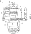
- FIG. 2 An example of an integrated drive generator 200 including a housing 202 is shown in FIG. 2 .
- the integrated drive generator 200 includes an input shaft 204 configured to receive rotational drive from an accessory drive gearbox (see FIG. 1 ).
- the rotational speed of the input shaft 204 varies depending upon the operation of the engine (see FIG. 1 ).
- a hydraulic unit 206 cooperates with a differential assembly 208 to convert the variable rotational speed from the input shaft 204 to a fixed rotational output speed that is transferred to a generator 210.
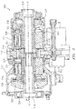
- the hydraulic unit 300 includes a variable displacement hydraulic pump 302 and a fixed displacement hydraulic motor 304.
- the variable displacement hydraulic pump 302 and the fixed displacement hydraulic motor 304 have respective cylinder block assemblies 306 and 308 which are arranged for rotation about a common axis A within housings 310, 311 on opposite sides of a stationary port plate 312 of the hydraulic unit 300.
- the port plate 312 is formed with one or more kidneys or apertures 314 through which hydraulic fluid communication between the pump 302 and the motor 304 is established during normal operation of the hydraulic unit 300.
- a biasing mechanism 316 resiliently biases the cylinder block assemblies 306, 308 in the direction of the port plate 312.
- the operation of the hydraulic unit 300 in an integrated drive generator involves transmission of torque from an engine of the aircraft to an input, which rotates an input shaft 318 of the hydraulic unit 300 about axis A.
- the cylinder block assembly 306 of the pump 302 is connected to the input shaft 318 for rotation therewith.
- Pistons 320 within the cylinder block assembly 306 of the pump 302 are displaced during rotation an amount which is a function of the setting of a variable swash plate or wobbler 322 of the pump 302.
- Pistons 321 within the cylinder block assembly 308 of the motor 304 are displaced during rotation with respect to a fixed swash plate or wobbler 326 of the motor 304.
- the system may include nine pistons 320, 321 in each of the motor 304 and the pump 302, and nine apertures 314 may pass through the port plate 312.
- the number of apertures 314 is not dependent on the number of pistons 320, 321, and in some embodiments there may be five apertures 314 when nine pistons 320, 321 are employed.
- the number of pistons 320, 321 and the number apertures 314 may be varied without departing from the scope of the invention.
- Hydraulic fluid under pressure from the hydraulic pump 302 is delivered to the hydraulic motor 304 through the apertures 314 of port plate 312 for rotating the cylinder block assembly 308 and an output shaft 324 to which the cylinder block assembly 308 is fixedly connected.
- the swash plate or wobbler 326 of the motor 304 is fixedly configured so that an operating speed of the motor 304 is a function of a displacement of the pump 302.
- the rotary output from output shaft 324 is added to or subtracted from the rotary motion from the engine through a conventional differential gearing of an integrated drive generator for operating an electrical generator at a substantially constant rotational speed.
- the position of the variable wobbler 322 is adjusted in response to these detected speed variations for providing the necessary reduction or increase in the rotational speed for obtaining a desired constant output speed to the generator.
- the hydraulic unit 300 illustrated and described herein refers to the variable unit as a pump 302 and the fixed unit as a motor 304, hydraulic units having other configurations, such as where the variable unit functions as a motor and the hydraulic unit operates as a pump for example, are within the scope of the invention.
- the wobbler 322 is permitted to turn, rotate, tumble, and/or wobble about a retainer ball 328.
- the wobbler 322 is configured to wobble, etc., in part, as a result of the movement of the pistons 320, 321, respectively.
- a retainer ball 330 is configured to turn or rotate with respect to the wobbler 326.
- Each piston 320, 321 has a ball 332 (ball of piston 320 not labeled for clarity) on one end.
- the ball 332 of the pistons 320, 321 is retained within a slipper 334.
- the slipper 334 is retained by a slipper retainer 336.
- the slipper retainer 336 enables the slipper 334 to be held in contact with the wobbler 322, 326, thus enabling operational coupling and/or contact between the wobblers 322, 326 and the pistons 320, 321, respectively, of the pump 302 and the motor 304.
- FIG. 4 an isometric view of a cylinder block assembly 400 is depicted in accordance with an embodiment of the invention.
- the cylinder block assembly 400 is an embodiment of the cylinder block assemblies 306 and 308 of FIG. 3 .
- the cylinder block assembly 400 includes a cylinder block 402 and a plurality of piston bores 404 arranged circumferentially about a central axis A of the cylinder block assembly 400 and extending through a first face 406 of the cylinder block 402.
- a shaft interface 408 extends from an inner portion 409 (i.e., closer to the central axis A) of the first face 406 of the cylinder block 402 and has an outer edge 410.
- the cylinder block assembly 400 also includes a balance plate 414 that is coupled to a second face 412 of the cylinder block 402.
- the balance plate 414 has an outer face 416 that defines a balance land to establish hydrostatic balance with the port plate 312 of FIG. 3 .
- FIG. 5 is a side plan view of the cylinder block assembly 400 of FIG. 4 .
- a cylinder block assembly total length L1 is defined between the outer edge 410 of the shaft interface 408 and the outer face 416 of the balance plate 414.
- a cylinder block assembly outer length L2 is defined between the first face 406 of the cylinder block 402 and the outer face 416 of the balance plate 414.
- the cylinder block assembly total length L1 is about 1.634 inches (4.150 cm), and the cylinder block assembly outer length L2 is about 1.266 inches (3.216 cm).
- FIG. 6 is a plan view of the balance plate 414 of the cylinder block assembly 400 of FIG. 4 .
- Each of the piston bores 404 has a piston bore axis B, as best seen in FIG. 7 .
- Each of the piston bores 404 also has a pitch diameter D1 defined radially with respect to the central axis A of the cylinder block assembly 400 such that each piston bore axis B is radially offset from the central axis A by a value of D1/2.
- the balance plate 414 includes a plurality of apertures 418 that align with pressure ports 420, as best seen in FIG. 7 , where both the apertures 418 and pressure ports 420 have a diameter D5.
- the outer face 416 of the balance plate 414 defines a balance land having balance land outer diameter D2 and a balance land inner diameter D3, as best seen in FIG. 7 .
- the pitch diameter D1 is about 1.592 inches (4.044 cm)
- the balance land outer diameter D2 is about 1.977 inches (5.022 cm)
- the balance land inner diameter D3 is about 1.207 inches (3.066 cm).
- FIG. 7 is a cross-sectional view of the cylinder block assembly 400 of FIG. 4 as viewed along the line A-A of FIG. 6 .
- the second face 412 of the cylinder block 402 includes a plurality of pressure ports 420 that extend from the piston bores 404.
- Each of the piston bores 404 has a piston bore diameter D4, where the diameter D5 of each of the pressure ports 420 is smaller than the piston bore diameter D4.
- a piston relief 422 having a piston relief diameter D6 is defined between each pairing of the piston bores 404 and the pressure ports 420.
- the shaft interface 408 has a smaller diameter D7 than the pitch diameter D1.
- the piston bore diameter D4 is about 0.46 inches (1.168 cm)
- the piston relief diameter D6 is about 0.476 inches (1.209 cm).
- a number of ratios are defined between multiple features of the cylinder block assembly 400 of FIGS. 4-7 .
- a ratio of the pitch diameter D1 to the cylinder block assembly outer length L2 is between 1.24 and 1.27.
- a ratio of the pitch diameter D1 to the piston bore diameter D4 is between 3.44 and 3.48.
- a ratio of the cylinder block assembly outer length L2 to the piston bore diameter D4 is between 2.73 and 2.77.
- a ratio of the balance land outer diameter D2 to the pitch diameter D1 is between 1.23 and 1.25.
- a ratio of the balance land outer diameter D2 to the piston bore diameter D4 is between 4.28 and 4.32.
- a ratio of the balance land inner diameter D3 to the pitch diameter D1 is between 0.75 and 0.77.
- a ratio of the balance land inner diameter D3 to the piston bore diameter D4 is between 2.60 and 2.65.
- a ratio of the balance land outer diameter D2 to the balance land inner diameter D3 is between 1.62 and 1.65.
- a ratio of the piston relief diameter D6 to the piston bore diameter D4 is between 1.02 and 1.05.
- a ratio of the cylinder block assembly total length L1 to the cylinder block assembly outer length L2 is between 1.28 and 1.30.
- a method of assembling a hydraulic unit includes biasing a cylinder block assembly, such as one of the cylinder block assemblies 306 and 308 of FIG. 3 , toward port plate 312 using, for example, biasing mechanism 316.
- the cylinder block 402 includes a plurality of piston bores 404 arranged circumferentially about a central axis A of the cylinder block assembly 400, and the piston bores 404 extend through the first face 406 of the cylinder block 402, where each of the piston bores 404 has a pitch diameter D1 defined radially with respect to the central axis A of the cylinder block assembly 400.
- the cylinder block 402 also includes a second face 412 having a plurality of pressure ports 420 that extend from the piston bores 404, where each of the pressure ports 420 has a smaller diameter D5 than a piston bore diameter D4 of each of the piston bores 404.
- Balance plate 414 is coupled to the second face 412 of the cylinder block 402, where the balance plate 414 includes a plurality of apertures 418 that align with the pressure ports 420.
- the outer face 416 of the balance plate 414 is proximate the port plate 312.
- Pistons 320, 321 of FIG. 3 can be arranged in the piston bores 404.
- the cylinder block assembly 400 also interfaces with a shaft, such as the input shaft 318 or the output shaft 324 of FIG. 3 , through shaft interface 408 that extends from the first face 406 of the cylinder block 402.
Landscapes
- Engineering & Computer Science (AREA)
- Mechanical Engineering (AREA)
- General Engineering & Computer Science (AREA)
- Chemical & Material Sciences (AREA)
- Combustion & Propulsion (AREA)
- Reciprocating Pumps (AREA)
Applications Claiming Priority (1)
| Application Number | Priority Date | Filing Date | Title |
|---|---|---|---|
| US14/661,582 US20160273531A1 (en) | 2015-03-18 | 2015-03-18 | Cylinder block assembly for hydraulic unit |
Publications (1)
| Publication Number | Publication Date |
|---|---|
| EP3070330A1 true EP3070330A1 (de) | 2016-09-21 |
Family
ID=55661194
Family Applications (1)
| Application Number | Title | Priority Date | Filing Date |
|---|---|---|---|
| EP16160853.4A Withdrawn EP3070330A1 (de) | 2015-03-18 | 2016-03-17 | Zylinderblockanordnung für hydraulikaggregat |
Country Status (2)
| Country | Link |
|---|---|
| US (1) | US20160273531A1 (de) |
| EP (1) | EP3070330A1 (de) |
Families Citing this family (2)
| Publication number | Priority date | Publication date | Assignee | Title |
|---|---|---|---|---|
| US10539213B2 (en) * | 2017-10-03 | 2020-01-21 | Hamilton Sundstrand Corporation | Hydraulic unit cylinder block for integrated drive generator |
| US11898582B1 (en) | 2023-03-09 | 2024-02-13 | Dana Motion Systems Italia S.R.L. | System for a bent axis motor |
Citations (2)
| Publication number | Priority date | Publication date | Assignee | Title |
|---|---|---|---|---|
| US3585901A (en) * | 1969-02-19 | 1971-06-22 | Sundstrand Corp | Hydraulic pump |
| US20140009126A1 (en) * | 2012-07-06 | 2014-01-09 | Henry R. Vanderzyden | Integrated drive generator pump plate |
Family Cites Families (1)
| Publication number | Priority date | Publication date | Assignee | Title |
|---|---|---|---|---|
| US3089426A (en) * | 1958-09-17 | 1963-05-14 | New York Air Brake Co | Engine |
-
2015
- 2015-03-18 US US14/661,582 patent/US20160273531A1/en not_active Abandoned
-
2016
- 2016-03-17 EP EP16160853.4A patent/EP3070330A1/de not_active Withdrawn
Patent Citations (2)
| Publication number | Priority date | Publication date | Assignee | Title |
|---|---|---|---|---|
| US3585901A (en) * | 1969-02-19 | 1971-06-22 | Sundstrand Corp | Hydraulic pump |
| US20140009126A1 (en) * | 2012-07-06 | 2014-01-09 | Henry R. Vanderzyden | Integrated drive generator pump plate |
Also Published As
| Publication number | Publication date |
|---|---|
| US20160273531A1 (en) | 2016-09-22 |
Similar Documents
| Publication | Publication Date | Title |
|---|---|---|
| EP2541741A1 (de) | Wellengetriebener doppelstator-mehrgeschwindigkeitsmotor mit krümmungen von gleicher breite | |
| US20110314963A1 (en) | Controllable constant speed gearbox | |
| EP3045721A1 (de) | Variables taumelelement für hydraulikeinheit | |
| EP3070330A1 (de) | Zylinderblockanordnung für hydraulikaggregat | |
| US9714702B2 (en) | Variable coaxial shaft for hydraulic unit | |
| US2872875A (en) | Hydraulic power units | |
| EP3514351B1 (de) | Anschlussplatte für einen integrierten antriebsgenerator | |
| US3522759A (en) | Pump or motor device | |
| US9845679B2 (en) | Port plate assembly for hydraulic unit | |
| EP3023651B1 (de) | Festwelle für hydraulikeinheit | |
| EP3048302B1 (de) | Gleitschuhhalter für hydraulikeinheit | |
| EP3483443B1 (de) | Pumpenhülse für einen integrierten antriebsgenerator | |
| US9435378B1 (en) | Roller bearing outer race for hydraulic unit | |
| EP3073111A1 (de) | Kolben- und gleitschuhanordnung für eine hydraulikbaugruppe | |
| US20240124126A1 (en) | System and method for controlling the modification of the pitch of the blades of a turbine engine | |
| EP3061965B1 (de) | Wälzlageraussenring einer hydraulikeinheit | |
| EP3045720B1 (de) | Gleitschuhhalterkugel für hydraulikeinheit | |
| US10707792B2 (en) | Variable wobbler plate for integrated drive generator | |
| EP3511595B1 (de) | Variable blockwelle für einen integrierten antriebsgenerator | |
| US10422324B2 (en) | Wear ring for integrated drive generator | |
| EP3045722B1 (de) | Fester wobbler für hydraulikbaugruppe |
Legal Events
| Date | Code | Title | Description |
|---|---|---|---|
| PUAI | Public reference made under article 153(3) epc to a published international application that has entered the european phase |
Free format text: ORIGINAL CODE: 0009012 |
|
| AK | Designated contracting states |
Kind code of ref document: A1 Designated state(s): AL AT BE BG CH CY CZ DE DK EE ES FI FR GB GR HR HU IE IS IT LI LT LU LV MC MK MT NL NO PL PT RO RS SE SI SK SM TR |
|
| AX | Request for extension of the european patent |
Extension state: BA ME |
|
| 17P | Request for examination filed |
Effective date: 20170317 |
|
| RBV | Designated contracting states (corrected) |
Designated state(s): AL AT BE BG CH CY CZ DE DK EE ES FI FR GB GR HR HU IE IS IT LI LT LU LV MC MK MT NL NO PL PT RO RS SE SI SK SM TR |
|
| 17Q | First examination report despatched |
Effective date: 20171010 |
|
| STAA | Information on the status of an ep patent application or granted ep patent |
Free format text: STATUS: THE APPLICATION IS DEEMED TO BE WITHDRAWN |
|
| 18D | Application deemed to be withdrawn |
Effective date: 20180221 |