EP3069807A1 - Drilling machine and method of manufacturing drilled product - Google Patents
Drilling machine and method of manufacturing drilled product Download PDFInfo
- Publication number
- EP3069807A1 EP3069807A1 EP16155137.9A EP16155137A EP3069807A1 EP 3069807 A1 EP3069807 A1 EP 3069807A1 EP 16155137 A EP16155137 A EP 16155137A EP 3069807 A1 EP3069807 A1 EP 3069807A1
- Authority
- EP
- European Patent Office
- Prior art keywords
- drilling
- travelling
- machine
- drilled
- elongated structural
- Prior art date
- Legal status (The legal status is an assumption and is not a legal conclusion. Google has not performed a legal analysis and makes no representation as to the accuracy of the status listed.)
- Granted
Links
Images



Classifications
-
- B—PERFORMING OPERATIONS; TRANSPORTING
- B23—MACHINE TOOLS; METAL-WORKING NOT OTHERWISE PROVIDED FOR
- B23Q—DETAILS, COMPONENTS, OR ACCESSORIES FOR MACHINE TOOLS, e.g. ARRANGEMENTS FOR COPYING OR CONTROLLING; MACHINE TOOLS IN GENERAL CHARACTERISED BY THE CONSTRUCTION OF PARTICULAR DETAILS OR COMPONENTS; COMBINATIONS OR ASSOCIATIONS OF METAL-WORKING MACHINES, NOT DIRECTED TO A PARTICULAR RESULT
- B23Q9/00—Arrangements for supporting or guiding portable metal-working machines or apparatus
- B23Q9/0014—Portable machines provided with or cooperating with guide means supported directly by the workpiece during action
- B23Q9/0042—Portable machines provided with or cooperating with guide means supported directly by the workpiece during action the guide means being fixed only on the workpiece
- B23Q9/0057—Portable machines provided with or cooperating with guide means supported directly by the workpiece during action the guide means being fixed only on the workpiece and being capable of guiding the tool in a circular path
-
- B—PERFORMING OPERATIONS; TRANSPORTING
- B23—MACHINE TOOLS; METAL-WORKING NOT OTHERWISE PROVIDED FOR
- B23B—TURNING; BORING
- B23B39/00—General-purpose boring or drilling machines or devices; Sets of boring and/or drilling machines
- B23B39/14—General-purpose boring or drilling machines or devices; Sets of boring and/or drilling machines with special provision to enable the machine or the drilling or boring head to be moved into any desired position, e.g. with respect to immovable work
-
- B—PERFORMING OPERATIONS; TRANSPORTING
- B23—MACHINE TOOLS; METAL-WORKING NOT OTHERWISE PROVIDED FOR
- B23B—TURNING; BORING
- B23B41/00—Boring or drilling machines or devices specially adapted for particular work; Accessories specially adapted therefor
-
- B—PERFORMING OPERATIONS; TRANSPORTING
- B23—MACHINE TOOLS; METAL-WORKING NOT OTHERWISE PROVIDED FOR
- B23B—TURNING; BORING
- B23B41/00—Boring or drilling machines or devices specially adapted for particular work; Accessories specially adapted therefor
- B23B41/003—Boring or drilling machines or devices specially adapted for particular work; Accessories specially adapted therefor for drilling elongated pieces, e.g. beams
- B23B41/006—Boring or drilling machines or devices specially adapted for particular work; Accessories specially adapted therefor for drilling elongated pieces, e.g. beams the machining device being moved along a fixed workpiece
-
- B—PERFORMING OPERATIONS; TRANSPORTING
- B23—MACHINE TOOLS; METAL-WORKING NOT OTHERWISE PROVIDED FOR
- B23Q—DETAILS, COMPONENTS, OR ACCESSORIES FOR MACHINE TOOLS, e.g. ARRANGEMENTS FOR COPYING OR CONTROLLING; MACHINE TOOLS IN GENERAL CHARACTERISED BY THE CONSTRUCTION OF PARTICULAR DETAILS OR COMPONENTS; COMBINATIONS OR ASSOCIATIONS OF METAL-WORKING MACHINES, NOT DIRECTED TO A PARTICULAR RESULT
- B23Q9/00—Arrangements for supporting or guiding portable metal-working machines or apparatus
- B23Q9/0007—Portable machines comprising means for their guidance or support directly on the workpiece
-
- B—PERFORMING OPERATIONS; TRANSPORTING
- B23—MACHINE TOOLS; METAL-WORKING NOT OTHERWISE PROVIDED FOR
- B23Q—DETAILS, COMPONENTS, OR ACCESSORIES FOR MACHINE TOOLS, e.g. ARRANGEMENTS FOR COPYING OR CONTROLLING; MACHINE TOOLS IN GENERAL CHARACTERISED BY THE CONSTRUCTION OF PARTICULAR DETAILS OR COMPONENTS; COMBINATIONS OR ASSOCIATIONS OF METAL-WORKING MACHINES, NOT DIRECTED TO A PARTICULAR RESULT
- B23Q9/00—Arrangements for supporting or guiding portable metal-working machines or apparatus
- B23Q9/0014—Portable machines provided with or cooperating with guide means supported directly by the workpiece during action
- B23Q9/0042—Portable machines provided with or cooperating with guide means supported directly by the workpiece during action the guide means being fixed only on the workpiece
-
- B—PERFORMING OPERATIONS; TRANSPORTING
- B23—MACHINE TOOLS; METAL-WORKING NOT OTHERWISE PROVIDED FOR
- B23Q—DETAILS, COMPONENTS, OR ACCESSORIES FOR MACHINE TOOLS, e.g. ARRANGEMENTS FOR COPYING OR CONTROLLING; MACHINE TOOLS IN GENERAL CHARACTERISED BY THE CONSTRUCTION OF PARTICULAR DETAILS OR COMPONENTS; COMBINATIONS OR ASSOCIATIONS OF METAL-WORKING MACHINES, NOT DIRECTED TO A PARTICULAR RESULT
- B23Q9/00—Arrangements for supporting or guiding portable metal-working machines or apparatus
- B23Q9/02—Arrangements for supporting or guiding portable metal-working machines or apparatus for securing machines or apparatus to workpieces, or other parts, of particular shape, e.g. to beams of particular cross-section
-
- B—PERFORMING OPERATIONS; TRANSPORTING
- B64—AIRCRAFT; AVIATION; COSMONAUTICS
- B64F—GROUND OR AIRCRAFT-CARRIER-DECK INSTALLATIONS SPECIALLY ADAPTED FOR USE IN CONNECTION WITH AIRCRAFT; DESIGNING, MANUFACTURING, ASSEMBLING, CLEANING, MAINTAINING OR REPAIRING AIRCRAFT, NOT OTHERWISE PROVIDED FOR; HANDLING, TRANSPORTING, TESTING OR INSPECTING AIRCRAFT COMPONENTS, NOT OTHERWISE PROVIDED FOR
- B64F5/00—Designing, manufacturing, assembling, cleaning, maintaining or repairing aircraft, not otherwise provided for; Handling, transporting, testing or inspecting aircraft components, not otherwise provided for
- B64F5/10—Manufacturing or assembling aircraft, e.g. jigs therefor
-
- B—PERFORMING OPERATIONS; TRANSPORTING
- B23—MACHINE TOOLS; METAL-WORKING NOT OTHERWISE PROVIDED FOR
- B23B—TURNING; BORING
- B23B2215/00—Details of workpieces
- B23B2215/04—Aircraft components
-
- Y—GENERAL TAGGING OF NEW TECHNOLOGICAL DEVELOPMENTS; GENERAL TAGGING OF CROSS-SECTIONAL TECHNOLOGIES SPANNING OVER SEVERAL SECTIONS OF THE IPC; TECHNICAL SUBJECTS COVERED BY FORMER USPC CROSS-REFERENCE ART COLLECTIONS [XRACs] AND DIGESTS
- Y10—TECHNICAL SUBJECTS COVERED BY FORMER USPC
- Y10T—TECHNICAL SUBJECTS COVERED BY FORMER US CLASSIFICATION
- Y10T408/00—Cutting by use of rotating axially moving tool
- Y10T408/55—Cutting by use of rotating axially moving tool with work-engaging structure other than Tool or tool-support
- Y10T408/556—Tool supporting wheel
-
- Y—GENERAL TAGGING OF NEW TECHNOLOGICAL DEVELOPMENTS; GENERAL TAGGING OF CROSS-SECTIONAL TECHNOLOGIES SPANNING OVER SEVERAL SECTIONS OF THE IPC; TECHNICAL SUBJECTS COVERED BY FORMER USPC CROSS-REFERENCE ART COLLECTIONS [XRACs] AND DIGESTS
- Y10—TECHNICAL SUBJECTS COVERED BY FORMER USPC
- Y10T—TECHNICAL SUBJECTS COVERED BY FORMER US CLASSIFICATION
- Y10T408/00—Cutting by use of rotating axially moving tool
- Y10T408/91—Machine frame
Definitions
- Embodiments described herein relate generally to a drilling machine and a method of manufacturing a drilled product.
- An object of the present invention is to allow drilling a part of an aircraft or the like with a simpler structure.
- a drilling machine includes a drilling structure and a travelling machine.
- the drilling structure drills an object to be drilled composed of at least one structural object on a platy part.
- the travelling machine positions the drilling structure in a travelling direction of the travelling machine by travelling in a longitudinal direction of the at least one structural object using the at least one structural object as a guide.
- a method of manufacturing a drilled product using the above-mentioned drilling machine is provided.
- a method of manufacturing a drilled product includes: positioning a drilling structure in a travelling direction of a travelling machine by making the travelling machine travel in a longitudinal direction of at least one structural object of an object to be drilled; and manufacturing a drilled product by drilling the object to be drilled, using the drilling structure after the positioning.
- the drilling structure is coupled to the travelling machine.
- the travelling machine travels using the at least one structural object as a guide.
- the object to be drilled is composed of the at least one structural object on a platy part.
- FIG. 1 is a front view showing a structure of a drilling machine according to an embodiment of the present invention.
- FIG. 2 is a top view showing the structure of the drilling machine shown in FIG. 1 .
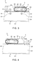
- FIG. 3 is a left side view showing a structure of the first travelling structure included in the drilling machine shown in FIG. 1 .
- FIG. 4 is a right side view showing a structure of the second travelling structure included in the drilling machine shown in FIG. 1 .
- a drilling machine 1 is a self-propelled automatic drilling machine which drills an object 0 to be drilled with travelling on the object 0 to be drilled.
- the object 0 to be drilled which is composed of a structural object 02 on a plate-like part 01 is a drilling target by the drilling machine 1.
- the object 0 to be drilled which has a structure of elongated structural objects 02, having webs 03 and flanges 04, on the plate-like part 01 is a drilling target. More specifically, portions of the webs 03 of the object 0 to be drilled are drilling targets.
- drilling plates T are attached to the webs 03 of the object 0 to be drilled.
- Examples of the object O to be drilled which has a structure of having the elongated structural objects 02 attached on the plate-like part 01 include a center wing of an aircraft.
- the center wing is a wing disposed between the right and left main wings of an aircraft. Therefore, the center wing is located at the bottom of a fuselage of an aircraft.
- the center wing has a structure of having seat rails, for fixing seats, attached on a curved surface-like panel.
- the object O to be drilled when the object O to be drilled is a center wing of an aircraft on which seat rails have been attached, the object O to be drilled has a structure of having the shaped metal-like structural objects 02 whose top surfaces are flat, as seat rails, disposed on a panel which is the non-flat plate-like part 01.
- Other examples of the object 0 to be drilled include a structural object for aircraft, such as a main wing, where sub-structural objects, such as stringers, ribs, and spars, having webs and flanges have been attached on a panel.
- a shaped metal i.e., a metal material which has a constant sectional shape, such as an I shape or an H shape, and is long in the direction of the material axis
- a shaped metal material which has a non-constant sectional shape and is long in the direction of the material axis can also be an example of the elongated structural object 02.
- a shaped metal-like structural object made of not only a metal material but also a composite material can also be an example of the elongated structural object 02.
- the drilling machine 1 can be composed of at least one drilling structure 2, at least one travelling machine 3, at least one position sensor 4, at least one IC (integrated circuit) tag reader 5, and a controlling device 6.
- Elements which perform information processing and/or control out of the elements composing the drilling machine 1 can be configured by circuitry, such as a computer.
- the drilling structure 2 is a device which drills the object 0 to be drilled with holding a tool, such as a drill.
- the drilling machine 1 has the two drilling structures 2. Therefore, drilling can be performed with two kinds of sizes.
- Each of the drilling structures 2 is a drill driving device which can perform a rotation and a feed of a tool, such as a drill.
- Each of the drilling structures 2 may also have a supply structure of a cutting oil and/or a dust collection structure for collecting chips, as necessary.
- Methods of supplying a cutting oil include a method of supplying a cutting oil through inside a tool, such as a drill, and a method of disposing a nozzle for supplying a cutting oil outside a tool.
- a general drill driving device which can operate a rotation, a feed, a return, and cutting oil supply by air signals from a single air supply system has been on the market. Therefore, when a commercially available air type drill driving device is diverted as the drilling structure 2, manufacturing costs of the drilling machine 1 can be reduced. Note that, not only limited to an air type structure but also a hydraulic structure or a structure driven by electric control may also be used in order to operate an arbitrary part of the drilling structure 2.
- the collet 2A is a device which clamps the head of the drilling structure 2 to the drilling plate T in a state where the collet 2A has been inserted in the drilling plate T. Specifically, when the tip of the head of the drilling structure 2 is pressed into the collet 2A which has been inserted in the drilling plate T, the collet 2A is pushed and expanded outside, thereby the head of the drilling structure 2 can be fixed to the drilling plate T through the collet 2A.
- Each of the drilling structures 2 is coupled directly or indirectly to the travelling machine 3 by a removable structure 7.
- each of the drilling structures 2 has been indirectly coupled to the travelling machine 3 through a feed structure 8, by the removable structure 7.
- the feed structure 8 is a device to move the drilling structure 2 itself in the tool axis direction.
- each of the feed structures 8 can be composed of a rack and pinion 8A, a feed motor 8B for rotating the pinion side of the rack and pinion 8A, and a feed guide 8C which guides a movement of the drilling structure 2.
- the rack is a toothed linear bar on which a gear cutting has been performed while the pinion is a small-diameter circular gear which meshes with the rack.
- the drilling structure 2, which has been installed slidably along the feed guide 8C is fixed to the rack side of the rack and pinion 8A. Meanwhile, the pinion of the rack and pinion 8A is rotated by the feed motor 8B. Thereby, the drilling structure 2 can be fed out in the tool axis direction of the drilling structure 2.
- the feed structure 8 may be omitted. Nevertheless, when the feed structure 8 of the drilling structure 2 is provided to the drilling machine 1, interference between the head of the drilling structure 2 and the structural object 02 can be avoided even when the structural object 02 has concavity and convexity in the tool axis direction.
- the removable structure 7 can be composed of positioning pins 7A, positioning holes 7B, a hook 7C, and a fixing knob 7D.
- the positioning pins 7A and the hook 7C are disposed in the drilling structure 2 side.
- the positioning holes 7B and the fixing knob 7D are disposed in a target side to which the drilling structure 2 is attached.
- the drilling structures 2 are attached to the feed structures 8 respectively. Therefore, the positioning holes 7B and the fixing knob 7D are disposed on each of the feed structures 8.
- Two sets of the positioning pin 7A and the positioning hole 7B are disposed so that the positioning pins 7A can be inserted into the positioning holes 7B, respectively. Therefore, the drilling structure 2 can be positioned by inserting the two positioning pins 7A into the positioning holes 7B respectively.
- the fixing knob 7D is configured to enable to be pulled up like a lever by a rotating shaft.
- the fixing knob 7D engages with the hook 7C attached to the drilling structure 2. Therefore, the drilling structure 2 can be fixed to the feed structure 8 by engagement between the fixing knob 7D and the hook 7C. That is, the drilling structure 2 can be positioned by the positioning pins 7A, and can be simply attached to the feed structure 8 and detached from the feed structure 8 by operating the fixing knob 7D.
- the feed structure 8 which is a target to attach and detach the drilling structure 2 is coupled to the travelling machine 3.
- the travelling machine 3 is a device which positions the drilling structure 2 in the travelling direction of the travelling machine 3 by travelling in the longitudinal direction of the elongated structural object 02 of the object 0 to be drilled, using the elongated structural object 02 as a guide.
- the travelling machine 3 can be composed using plural travelling structures 9 and an adjusting structure 10.
- Each of the travelling structures 9 is a device which travels using the elongated structural object 02 of the object O to be drilled as a guide.
- the adjusting structure 10 is a device which adjusts an interval between the travelling structures 9.
- the travelling machine 3 has the two travelling structures 9 according to positions of the two elongated structural objects 02, respectively.
- more than two travelling structures 9 may be provided according to positions of more than two elongated structural objects 02.
- two travelling structures 9 may be provided according to positions of arbitrary two elongated structural objects 02. That is, the travelling machine 3 can be composed of the plural travelling structures 9 which propel on at least two elongated structural objects 02 respectively.
- the travelling machine 3 has the two travelling structures 9 as shown in the figures will be described.
- the travelling machine 3 When the travelling machine 3 is provided with the adjusting structure 10 which adjusts an interval of the two travelling structures 9, the travelling machine 3 can travel using two selected elongated structural objects 02 as guides even when the object O to be drilled has more than two elongated structural objects 02 disposed at different intervals.
- the adjusting structure 10 can be composed of cylindrical sliders 10B, which slide along two rods 10A respectively, and a frame 10C, to which the cylindrical sliders 10B are coupled, as shown in the figures.
- a width of the adjusting structure 10 can be expanded or contracted by sliding the frame 10C along the two rods 10A in the longitudinal direction of the rods 10A.
- the frame 10C can be fixed to the rods 10A side by stoppers 10D. Therefore, when the adjusting structure 10 is disposed between the two travelling structures 9, an interval of the two travelling structures 9 can be adjusted by expansion and contraction of the adjusting structure 10.
- Each of the travelling structures 9 can be composed of a roller, a chain or the like.
- each of the travelling structures 9 has a chain 20 and a support roller 21 which travel on the flange 04 being the top surface of the elongated structural object 02, and underside guide rollers 22 which guide the undersurface of the flange 04.
- the travelling structure 9 in the drilling plate T side has external side rollers 23, which travel with contacting the web 03 from the horizontal direction, and internal side rollers 24, which travel with contacting the drilling plate T from the horizontal direction.
- the chain 20 which travels on the flange 04 is adapted to be driven by two sprockets 25 (gears which engage with the chain 20). Then, one sprocket 25 is fixed to one end of a drive shaft 26. Since each of the two travelling structures 9 has the chain 20 which travels on the flange 04, one sprockets 25 out of two sets of the two sprockets 25 included in the travelling structures 9 are to be fixed to both ends of the drive shaft 26. As a result, the sprockets 25 of the two travelling structures 9 are coupled to each other by the drive shaft 26.
- the drive shaft 26 of the sprockets 25 is coupled to a travelling motor 28 with a belt 27. Therefore, when the travelling motor 28 is driven, a rotative power is transmitted to the drive shaft 26 by the belt 27. Thereby, the two sprockets 25 as two wheels rotate with the drive shaft 26 so that the two chains 20 can be driven in the travelling direction along the longitudinal direction of the elongated structural objects 02. That is, the travelling machine 3 can travel in the travelling direction along the longitudinal direction of the elongated structural objects 02 by a drive of the chains 20.
- the travelling machine 3 is guided by the support rollers 21, the underside guide rollers 22, the external side rollers 23, and the internal side rollers 24 so that the travelling machine 3 can certainly travel along the elongated structural object 02. That is, even when the elongated structural object 02 has a complicated structure, such as a seat rail, which is not a rail for travelling originally, the elongated structural object 02 can be used as a rail for travelling by the travelling structure 9 which has a structure astride the elongated structural object 02.
- the elongated structural object 02 is a seat rail
- holes are formed on the flange 04 along the longitudinal direction.
- the object O to be drilled has a structure in which at least one elongated structural object 02 having holes along the travelling direction of the travelling machine 3 is attached on the plate-like part O1.
- projections 29, such as pins, which fit into the holes formed on at least one elongated structural object 02, such as a seat rail, can be formed on at least one travelling structure 9 of the travelling machine 3. Thereby, dropping of the travelling structure 9 or the travelling structures 9 can be prevented.
- the chain 20 of one travelling structure 9 has the projections 29 which fit into holes formed on the upper surface of the elongated structural object 02.
- the projections 29 may also be formed on the support roller 21.
- the chain 20 has a portion which linearly contacts on the upper surface of the elongated structural object 02, unlike a roller.
- the projections 29 which simultaneously fit into at least two holes out of the holes formed on the upper surface of the elongated structural object 02 can be formed on the chain 20.
- the travelling direction of the chain 20 can be directed to an array direction of the holes formed on the upper surface of the elongated structural object 02.
- a tool axis direction can be kept to be constant relative to the array direction of the holes of the elongated structural object 02.
- the travelling structure 9 has a travelling mechanism, such as a metal crawler or a belt, which contacts on the upper surface of the elongated structural object 02 linearly or planarly in the longitudinal direction, instead of the chain 20, the projections 29 which simultaneously fit into at least two holes out of the holes formed on the upper surface of the elongated structural object 02 can be also formed on the travelling structure 9.
- a travelling mechanism such as a metal crawler or a belt
- the projections 29 of the travelling structure 9 are generally formed linearly in the longitudinal direction at an equal interval. Therefore, when an interval of the projections 29 of the travelling structure 9 is determined according to a pitch of the through holes, the projections 29 can be simultaneously fit into at least two holes of a seat rail. Furthermore, even when holes are formed on the top surface of the elongated structural object 02 at unequal intervals, the projections 29 can be simultaneously fit into at least two holes by forming the projections 29 on the travelling structure 9 at an interval corresponding to the least common multiple of the intervals of the holes.
- a travelling direction of the travelling structure 9 and a tool axis direction can be directed to appropriate directions using the elongated structural object 02, such as a seat rail, which is not a rail for travelling originally.
- the travelling structure 9 can be made to travel on the basis of the holes formed on the top surface of the elongated structural object 02 while the tool axis direction can also be fixed.
- a slipping and a dropping of the travelling structure 9 can also be prevented certainly.
- a travelling direction of the travelling structures 9 and a tool axis direction can be appropriate directions on the basis of an array direction of holes formed on the elongated structural object 02 on which the chain 20 with the projections 29 travels even when an array direction of holes formed on the elongated structural object 02 on which the other chain 20 travels differs from the array direction of the holes formed on the elongated structural object 02 on which the chain 20 with the projections 29 travels. More specifically, when a travelling direction of the travelling structures 9 is perpendicular to a tool axis direction, a direction of tool can be constantly perpendicular to an array direction of holes formed on the elongated structural object 02.
- the travelling machine 3 has more than two travelling structures 9. That is, when the travelling machine 3 has the plural travelling structures 9 which travel at positions far from each other in a direction different from a travelling direction, it is appropriate to form the projections 29, which simultaneously fit into at least two holes out of holes of the elongated structural object 02, only on one travelling structure 9 out of the travelling structures 9. Then, the travelling machine 3 can be made to travel using one elongated structural object 02, arbitrarily selected from the elongated structural objects 02, as a guide.
- the external side rollers 23, which travel with contacting the web 03 from the horizontal direction, and the internal side rollers 24, which travel with contacting the drilling plate T from the horizontal direction, can also be disposed only in the travelling structure 9 in the drilling plate T side.
- the external side rollers 23 and the internal side rollers 24 can be made to travel on only one elongated structural object 02 arbitrarily selected from the elongated structural objects 02 and the drilling plate T attached to the selected elongated structural object 02.
- the drilling machine 1 can further have the position sensors 4 and the IC tag reader 5 to allow automatically controlling travelling of the travelling machine 3 and drilling by the drilling structures 2.
- Each position sensor 4 detects a position of the drilling plate T attached to the object 0 to be drilled.
- the IC tag reader 5 is an information reading device which reads information recorded in each IC tag 30 attached directly or indirectly to the object 0 to be drilled.
- the IC tags 30 are attached to the drilling plates T.
- FIG. 5 shows the drilling plates T shown in FIG. 1 as viewed from the right direction.
- the platy drilling plates T can be attached to the drilling side of the web 03 with fastening tools, such as bolts, along the longitudinal direction of the elongated structural object 02.
- the two drilling plates T have been disposed side by side with each other.
- the through holes for guide, corresponding to drilling positions of the elongated structural object 02, are formed on each drilling plate T.
- the IC tags 30 can be attached on each drilling plate T.
- the position sensors 4 can be configured by laser displacement sensors each irradiating a laser toward the top surface of each drilling plate T. Then, the end portions of the drilling plates T can be detected by the position sensors 4. Specifically, an existing range of the drilling plates T can be detected by a binary detected signal showing whether a laser reflected on the top surface of the drilling plate T has been detected by the position sensor 4.
- the drilling machine 1 has the position sensor 4 for detecting one end portion of the combined drilling plates T and the position sensor 4 for detecting the other end portion of the drilling plates T.
- detecting not the object 0 to be drilled but the drilling plates T each disposed as a drilling jig makes it possible to detect a relative positional relationship between the object 0 to be drilled and the drilling machine 1, using the simple and common position sensors 4, regardless of a structure of the object 0 to be drilled.
- Each IC tag 30 attached on the drilling plates T records information for identifying (ID information) the corresponding drilling plate T and information for selecting the drilling structure 2. Since the number of the drilling structures 2 is two, the two IC tags 30 corresponding to the two drilling structures 2 have been attached on each of the drilling plates T in the example shown in FIG. 5 .
- the IC tags 30 on the drilling plates T allow automatic control including automatic travelling and automatic drilling of the drilling machine 1 using RFID (radio frequency identifier) technique.
- the RFID is the technique which obtains ID information by wireless from an RF tag, such as an IC tag, in which the ID information has been recorded.
- the IC tag reader 5 of the drilling machine 1 is disposed at a position at which the IC tag reader 5 can read IC tag information from each of the IC tags 30 attached on the drilling plates T.
- the IC tag information including the ID information of the drilling plate T and the information for selecting the drilling structure 2, which have been read by the IC tag reader 5, is transferred to the controlling device 6 by wireless.
- the positional information of an end portion of the drilling plates T detected by any one of the position sensors 4 is also transferred to the controlling device 6 by wireless.
- the controlling device 6 which is configured by electronic circuitry, such as a computer, controls each element of the drilling machine 1. Specifically, the controlling device 6 controls drives of the drilling structures 2, drives of the feed structures 8, and travelling of the travelling machine 3. From a viewpoint of a weight reduction of a load to be mounted on the travelling machine 3, the controlling device 6 can remotely control the drilling structures 2, the feed structures 8, and the travelling machine 3 with wireless, instead of loading the whole controlling device 6 on the travelling machine 3.
- the controlling device 6 can be composed of a main part 6A and a control signal receiver 6B.
- the main part 6A is not loaded on the travelling machine 3.
- the control signal receiver 6B is loaded on the travelling machine 3 and performs wireless communication with the main part 6A.
- the control signal receiver 6B has been disposed above the adjusting structure 10 which adjusts an interval of the travelling structures 9.
- the main part 6A of the controlling device 6 has a function to remotely control the travelling machine 3, the feed structures 8, and the drilling structures 2 based on positions of the drilling plates T, which have been detected by the position sensors 4 attached on the travelling machine 3, and information read by the IC tag reader 5. That is, the main part 6A has a function to generate control signals of the drilling structures 2, the feed structures 8, and the travelling machine 3, based on the positions of the drilling plates T detected by the position sensors 4 and the information read by the IC tag reader 5, and to transmit the generated control signals to the control signal receiver 6B by wireless.
- control signal receiver 6B of the controlling device 6 has a function to receive the respective control signals of the drilling structures 2, the feed structures 8, and the travelling machine 3, transmitted from the main part 6A by wireless, and output the control signals to target devices respectively.
- the drilling structures 2, the feed structures 8, and the travelling machine 3 are configured to be driven according to control signals output from the control signal receiver 6B.
- control signals output from the control signal receiver 6B to a device driven by compressed air may also be air signals.
- the position sensors 4 detect positions of the both end portions of the drilling plates T. Therefore, the travelling direction of the travelling machine 3 can be controlled based on the positions of the drilling plates T detected by the position sensors 4. Specifically, when one end portion of the drilling plates T has been detected, a control signal which directs stop of the travelling machine 3 or reversal of the travelling direction of the travelling machine 3 can be transmitted from the main part 6A to the control signal receiver 6B by wireless. Thereby, when the travelling machine 3 has arrived at one end portion of the drilling plates T, the travelling machine 3 can be made to stop or reverse the travelling direction immediately. Thus, dropping of the travelling machine 3 can be prevented by the remote control in addition to the mechanical structure.
- ID information of the drilling plate T and information for selecting the drilling structure 2, which have been read by the IC tag reader 5, are used for specifying drilling positions.
- information showing a relationship between ID information of each drilling plate T and drilling positions is previously stored in the main part 6A.
- the drilling positions can be expressed as one-dimensional positional information, i.e., a pitch between adjacent holes or distances from a reference position to the respective holes. Therefore, storing a table, showing a relationship between sets of ID information of the drilling plates T and sets of one-dimensional drilling positions, in the main part 6A makes it possible to specify drilling positions based on ID information of a certain drilling plate T.
- holes, which have two diameters, arranged on straight lines different from each other are drilling targets of the object 0 to be drilled. Accordingly, holes having two diameters have also been arranged on straight lines different from each other on the two drilling plates T.
- the holes having one diameter can be determined to drilling targets by one drilling structure 2 while the holes having the other diameter can be determined to drilling targets by the other drilling structure 2.
- holes having two kinds of sizes can be formed on the elongated structural object 02 by making the travelling machine 3 reciprocate on the elongated structural objects 02. That is, one drilling structure 2 can process holes having one diameter in the outward path of the travelling machine 3 while the other drilling structure 2 can process holes having the other diameter in the return path of the travelling machine 3.
- the drilling structures 2 may be provided with an adjusting structure for adjusting their positions in the height direction.
- the positions of the holes, having one diameter, on the drilling plates T are drilling positions by one drilling structure 2 while the positions of the holes, having the other diameter, on the drilling plates T are drilling positions by the other drilling structure 2.
- the IC tag 30 on which information for selecting one drilling structure 2 and ID information of the drilling plate T have been recorded can be attached on the end portion of the corresponding drilling plate T where the IC tag reader 5 can read the information recorded on the IC tag 30 when the one drilling structure 2 is on an initial position before a start of drilling, as exemplified in FIG. 5 .
- the IC tag 30 on which information for selecting the other drilling structure 2 and ID information of the drilling plate T have been recorded can also be attached on the end portion of the corresponding drilling plate T where the IC tag reader 5 can read the information recorded on the IC tag 30 when the other drilling structure 2 is on an initial position before a start of drilling.
- drilling positions can be specified in the main part 6A, at a drilling start time, based on information for selecting the drilling structure 2 and ID information of the drilling plate T. That is, when a position of one drilling structure 2 has become an initial position before a start of drilling, positions to be drilled can be specified.
- control signals which instruct movement distances of the travelling machine 3 and control signals which instruct operations of the drilling structure 2 and the feed structure 8 to be driven can be generated. Then, the generated control signals can be output from the main part 6A, through the control signal receiver 6B, to the travelling machine 3, the feed structure 8, and the drilling structure 2.
- fixing the drilling plates T, to which the IC tags 30 have been attached, to the object O to be drilled and installing the position sensors 4 and the IC tag reader 5 in the travelling machine 3 allow remote operations of the drilling structures 2, the feed structures 8, and the travelling machine 3. That is, automatic control, including automatic travelling, of the drilling machine 1 can be performed using the elongated structural object 02, such as a seat rail, which is not a rail for travelling originally, as a guide.
- the drilling plates T In the case of manufacturing a drilled product using the drilling machine 1, the drilling plates T, to which the IC tags 30 have been attached, are attached to the elongated structural object 02 of the object 0 to be drilled, as shown in FIG. 5 .
- ID information of a corresponding drilling plate T and information for selecting one of the drilling structures 2 are previously stored in each IC tag 30. Note that, information showing a size of holes may be stored instead of the information for selecting the drilling structure 2.
- drills according to sizes of holes to be drilled are installed to the drilling structures 2, respectively.
- the drills can be installed in a state where the drilling structures 2 have been detached from the travelling machine 3, respectively.
- each of the drilling structures 2 is installed to the feed structure 8 by the removable structure 7. Thereby, the drilling structures 2 are coupled to the travelling machine 3.
- the travelling machine 3 equipped with the drilling structures 2 are placed on the elongated structural objects 02 of the object 0 to be drilled.
- the projections 29 formed on one travelling structure 9 are inserted into the holes of one elongated structural object 02.
- drilling can be started with directing a travelling direction of the travelling structures 9 to the array direction of the holes formed on the elongated structural object 02, and preventing a dropping of the travelling structures 9 from the elongated structural objects 02.
- ID information of the drilling plate T and information for selecting one drilling structure 2, which have been recorded on the IC tag 30 of the drilling plate T are read by the IC tag reader 5 attached to the travelling machine 3.
- the ID information of the drilling plate T and the information for selecting one drilling structure 2, which have been read by the IC tag reader 5, are transferred to the main part 6A of the controlling device 6 by wireless.
- the main part 6A specifies drilling positions corresponding to the one selected drilling structure 2, by referring to reference information which relates pieces of the ID information of the drilling plates T with sets of drilling positions.
- the main part 6A generates control signals, which instruct the travelling machine 3 to move to the specified drilling positions, and control signals, which instruct respective drives of the one selected drilling structure 2 and the corresponding feed structure 8.
- the respective generated control signals are transmitted from the main part 6A to the control signal receiver 6B by wireless.
- the control signal receiver 6B instructs the travelling machine 3 to move to the drilling positions by the control signals.
- the travelling machine 3 travels in the longitudinal direction of the elongated structural object 02 of the object 0 to be drilled, using the elongated structural object 02 as a guide.
- the travelling machine 3 arrives at the initial drilling position, the travelling machine 3 is stopped.
- the drilling structure 2 coupled to the travelling machine 3 can be positioned in the travelling direction.
- the tool axis direction of the drilling structure 2 can be directed perpendicular to the array direction of the holes formed on the elongated structural object 02.
- the control signal receiver 6B gives driving signals to the drilling structure 2 and the feed structure 8, respectively.
- the drilling structure 2 is given a feeding operation by a drive of the feed structure 8.
- drilling at the initial drilling position of the elongated structural object 02 can be performed by a drive of the drilling structure 2.
- the drill attached to the drilling structure 2 returns to the initial position, and the drilling structure 2 also returns to the initial position by a drive of the feed structure 8.
- the end portion of the drilling plate T is detected by one of the position sensors 4.
- detection information of the end portion of the drilling plate T is transferred to the main part 6A of the controlling device 6 by wireless. Then, the main part 6A generates a control signal for inverting the travelling direction of the travelling machine 3.
- ID information of the drilling plate T and information for selecting the other drilling structure 2, which have been recorded on the IC tag 30 disposed near the end portion of the drilling plate T are read by the IC tag reader 5.
- the ID information of the drilling plate T and the information for selecting the other drilling structure 2, which have been read by the IC tag reader 5, are transferred to the main part 6A of the controlling device 6 by wireless.
- the main part 6A specifies drilling positions corresponding to the other drilling structure 2 by referring to the reference information which relates the pieces of the ID information of the drilling plates T with the sets of the drilling positions.
- the main part 6A generates control signals, which instruct the travelling machine 3 to move to the specified drilling positions, and control signals, which instruct respective drives of the other selected drilling structure 2 and the corresponding feed structure 8.
- the generated respective control signals are transmitted from the main part 6A to the control signal receiver 6B by wireless.
- drilling by the other drilling structure 2 is performed at each drilling position in a flow similar to that of the drilling by the first selected drilling structure 2. Specifically, positioning of the other drilling structure 2 by travelling of the travelling machine 3 and drilling by drives of the other drilling structure 2 and the feed structure 8 are sequentially performed for each drilling position. After that, when the travelling machine 3 travels to near the end portion of the elongated structural object 02, the end portion of the drilling plate T is detected by the other one of the position sensors 4. When the end portion of the drilling plate T is detected by the position sensor 4, detection information of the end portion of the drilling plate T is transferred to the main part 6A of the controlling device 6 by wireless.
- the main part 6A generates a control signal for stopping travelling of the travelling machine 3.
- the generated control signal is output to the travelling machine 3 through the control signal receiver 6B by wireless. Thereby, the travelling machine 3 is stopped and the drilling of the elongated structural object 02 can be completed.
- drilling can be performed similarly by attaching the drilling plates T and placing the travelling machine 3, equipped with the drilling structures 2, on the next elongated structural object 02 to be drilled. Then, when drilling of the all elongated structural objects 02 to be drilled by the drilling machine 1 is completed, a drilled product can be obtained. That is, a drilled product can be manufactured.
- the drilling machine 1 and a method of manufacturing a drilled product allow to drill an object 0 to be drilled, having a structure in which elongated structural objects 02 are disposed on a plate-like part O1 like a center wing having seat rails of an aircraft, with travelling using at least one elongated structural object 02 as a guide.
- the drilling machine 1 and the method of manufacturing a drilled product do not require dedicated rails for moving the drilling machine 1.
- a structure of the drilling machine 1 can be simplified.
- the travelling structure 9 striding over the elongated structural object 02 can prevent dropping of the drilling machine 1 from the elongated structural object 02.
- the travelling structure 9 can travel stably by inserting the projections 29 of the travelling structure 9 into the holes of the elongated structural object 02.
- the tool axis can be directed perpendicular to the array direction of the holes on the elongated structural object 02.
- the drilling plates T to which the IC tags 30 have been attached, the position sensors 4, and the IC tag reader 5 allow of specifying positions of the drilling plates T, drilling positions, and the drilling structure 2 used for drilling.
- the drilling structure 2 can be positioned by travelling of the travelling structures 9 without depending on the structure of the elongated structural object 02.
- the drilling machine 1 and the method of manufacturing a drilled product allow of using even the elongated structural object 02, such as a seat rail, which has an irregular structure and is not a rail for travelling originally, as a guide for travelling, by a structural feature and a feature with regard to control.
- the drilling machine 1 has a structure in which the drilling structures 2 can be easily attached to the travelling machine 3 and detached from the travelling machine 3. Thereby, in the case of carrying the drilling machine 1, the drilling machine 1 can be carried after detaching the drilling structures 2. That is, the drilling machine 1 can be easily carried by attaining a weight reduction of the drilling machine 1 at the time of carrying the drilling machine 1.
- the attachment, detachment, or replacement of the drill can be performed in a state where the drilling structures 2 have been detached from the travelling machine 3.
- labor required for setup work including attachment, detachment, or replacement of a drill can be reduced.
- the drilling structure 2 is a general drill driving device
- the drilling structure 2 can also be used for drilling in a state where the drilling structure 2 has been detached from the travelling machine 3.
- the plural travelling structures 9 travel on the top surfaces of the elongated structural objects 02, respectively.
- one of the travelling structures may travel on a plate-like part O1.
- the travelling structure which travels on the plate-like part 01 can have a simple structure, such as a wheel.
- the drilling structure 2 may change to a non-negligible extent by travelling on the plate-like part 01. For that reason, the drilling structure 2 may be provided with a moving structure which moves the drilling structure 2 in the height direction, i.e., in the direction perpendicular to both the travelling direction of the travelling machine 3 and the feed direction of a tool. That is, a moving structure which moves the drilling structure 2 in the two dimensional direction may be installed in the travelling machine 3.
- the IC tags 30 may be attached to the drilling plates T as long as information in the IC tags 30 can be read by the IC tag reader 5.
- the position sensors 4 may detect a position of the object 0 to be drilled, instead of positions of the drilling plates T.
Landscapes
- Engineering & Computer Science (AREA)
- Mechanical Engineering (AREA)
- Manufacturing & Machinery (AREA)
- Transportation (AREA)
- Aviation & Aerospace Engineering (AREA)
- Drilling And Boring (AREA)
- Perforating, Stamping-Out Or Severing By Means Other Than Cutting (AREA)
Abstract
Description
- Embodiments described herein relate generally to a drilling machine and a method of manufacturing a drilled product.
- Conventionally, a self-travelling drilling machine which has a travelling function has been proposed as a drilling machine which drills a part of an aircraft or the like (for example, refer to Japanese Patent Application Publication
JP 2007-526134 A Japanese Patent Application Publication JP 2006-502010 A - An object of the present invention is to allow drilling a part of an aircraft or the like with a simpler structure.
- In general, according to one embodiment, a drilling machine includes a drilling structure and a travelling machine. The drilling structure drills an object to be drilled composed of at least one structural object on a platy part. The travelling machine positions the drilling structure in a travelling direction of the travelling machine by travelling in a longitudinal direction of the at least one structural object using the at least one structural object as a guide.
- Further, according to one embodiment, a method of manufacturing a drilled product using the above-mentioned drilling machine is provided.
- Further, according to one embodiment, a method of manufacturing a drilled product includes: positioning a drilling structure in a travelling direction of a travelling machine by making the travelling machine travel in a longitudinal direction of at least one structural object of an object to be drilled; and manufacturing a drilled product by drilling the object to be drilled, using the drilling structure after the positioning. The drilling structure is coupled to the travelling machine. The travelling machine travels using the at least one structural object as a guide. The object to be drilled is composed of the at least one structural object on a platy part.
- In the accompanying drawings:
-
Fig. 1 is a front view showing a structure of a drilling machine according to an embodiment of the present invention; -
Fig. 2 is a top view showing the structure of the drilling machine shown inFIG. 1 ; -
Fig. 3 is a left side view showing a structure of the first travelling structure included in the drilling machine shown inFIG. 1 ; -
Fig. 4 is a right side view showing a structure of the second travelling structure included in the drilling machine shown inFIG. 1 ; and -
Fig. 5 shows the drilling plates T shown inFIG. 1 as viewed from the right direction; - A drilling machine and a method of manufacturing a drilled product according to embodiments of the present invention will be described with reference to the accompanying drawings.
-
FIG. 1 is a front view showing a structure of a drilling machine according to an embodiment of the present invention.FIG. 2 is a top view showing the structure of the drilling machine shown inFIG. 1 .FIG. 3 is a left side view showing a structure of the first travelling structure included in the drilling machine shown inFIG. 1 .FIG. 4 is a right side view showing a structure of the second travelling structure included in the drilling machine shown inFIG. 1 . - A
drilling machine 1 is a self-propelled automatic drilling machine which drills an object 0 to be drilled with travelling on the object 0 to be drilled. In particular, the object 0 to be drilled which is composed of astructural object 02 on a plate-like part 01 is a drilling target by thedrilling machine 1. In the example shown in the figures, the object 0 to be drilled which has a structure of elongatedstructural objects 02, havingwebs 03 andflanges 04, on the plate-like part 01 is a drilling target. More specifically, portions of thewebs 03 of the object 0 to be drilled are drilling targets. For that purpose, drilling plates T are attached to thewebs 03 of the object 0 to be drilled. - Examples of the object O to be drilled which has a structure of having the elongated
structural objects 02 attached on the plate-like part 01 include a center wing of an aircraft. The center wing is a wing disposed between the right and left main wings of an aircraft. Therefore, the center wing is located at the bottom of a fuselage of an aircraft. Thus, the center wing has a structure of having seat rails, for fixing seats, attached on a curved surface-like panel. - Therefore, when the object O to be drilled is a center wing of an aircraft on which seat rails have been attached, the object O to be drilled has a structure of having the shaped metal-like
structural objects 02 whose top surfaces are flat, as seat rails, disposed on a panel which is the non-flat plate-like part 01. Other examples of the object 0 to be drilled include a structural object for aircraft, such as a main wing, where sub-structural objects, such as stringers, ribs, and spars, having webs and flanges have been attached on a panel. - Note that, while a shaped metal, i.e., a metal material which has a constant sectional shape, such as an I shape or an H shape, and is long in the direction of the material axis is an example of the elongated
structural object 02, a shaped metal material which has a non-constant sectional shape and is long in the direction of the material axis can also be an example of the elongatedstructural object 02. Furthermore, a shaped metal-like structural object made of not only a metal material but also a composite material can also be an example of the elongatedstructural object 02. - The
drilling machine 1 can be composed of at least onedrilling structure 2, at least onetravelling machine 3, at least oneposition sensor 4, at least one IC (integrated circuit)tag reader 5, and a controllingdevice 6. Elements which perform information processing and/or control out of the elements composing thedrilling machine 1 can be configured by circuitry, such as a computer. - The
drilling structure 2 is a device which drills the object 0 to be drilled with holding a tool, such as a drill. In the example shown in the figures, thedrilling machine 1 has the twodrilling structures 2. Therefore, drilling can be performed with two kinds of sizes. Each of thedrilling structures 2 is a drill driving device which can perform a rotation and a feed of a tool, such as a drill. - Each of the
drilling structures 2 may also have a supply structure of a cutting oil and/or a dust collection structure for collecting chips, as necessary. Methods of supplying a cutting oil include a method of supplying a cutting oil through inside a tool, such as a drill, and a method of disposing a nozzle for supplying a cutting oil outside a tool. - A general drill driving device which can operate a rotation, a feed, a return, and cutting oil supply by air signals from a single air supply system has been on the market. Therefore, when a commercially available air type drill driving device is diverted as the
drilling structure 2, manufacturing costs of thedrilling machine 1 can be reduced. Note that, not only limited to an air type structure but also a hydraulic structure or a structure driven by electric control may also be used in order to operate an arbitrary part of thedrilling structure 2. - It is preferable to dispose a
collet 2A on each head of thedrilling structures 2 as shown in the figures. Thecollet 2A is a device which clamps the head of thedrilling structure 2 to the drilling plate T in a state where thecollet 2A has been inserted in the drilling plate T. Specifically, when the tip of the head of thedrilling structure 2 is pressed into thecollet 2A which has been inserted in the drilling plate T, thecollet 2A is pushed and expanded outside, thereby the head of thedrilling structure 2 can be fixed to the drilling plate T through thecollet 2A. - Each of the
drilling structures 2 is coupled directly or indirectly to thetravelling machine 3 by aremovable structure 7. In the example shown in the figures, each of thedrilling structures 2 has been indirectly coupled to thetravelling machine 3 through afeed structure 8, by theremovable structure 7. - The
feed structure 8 is a device to move thedrilling structure 2 itself in the tool axis direction. For example, each of thefeed structures 8 can be composed of a rack andpinion 8A, afeed motor 8B for rotating the pinion side of the rack andpinion 8A, and afeed guide 8C which guides a movement of thedrilling structure 2. The rack is a toothed linear bar on which a gear cutting has been performed while the pinion is a small-diameter circular gear which meshes with the rack. Specifically, thedrilling structure 2, which has been installed slidably along thefeed guide 8C, is fixed to the rack side of the rack andpinion 8A. Meanwhile, the pinion of the rack andpinion 8A is rotated by thefeed motor 8B. Thereby, thedrilling structure 2 can be fed out in the tool axis direction of thedrilling structure 2. - When a feeding operation of a tool is performed only by a feed function of tool provided in each of the
drilling structures 2, thefeed structure 8 may be omitted. Nevertheless, when thefeed structure 8 of thedrilling structure 2 is provided to thedrilling machine 1, interference between the head of thedrilling structure 2 and thestructural object 02 can be avoided even when thestructural object 02 has concavity and convexity in the tool axis direction. - The
removable structure 7 can be composed ofpositioning pins 7A,positioning holes 7B, ahook 7C, and afixing knob 7D. The positioning pins 7A and thehook 7C are disposed in thedrilling structure 2 side. Meanwhile, thepositioning holes 7B and the fixingknob 7D are disposed in a target side to which thedrilling structure 2 is attached. In the example shown in the figures, thedrilling structures 2 are attached to thefeed structures 8 respectively. Therefore, thepositioning holes 7B and the fixingknob 7D are disposed on each of thefeed structures 8. - Two sets of the
positioning pin 7A and thepositioning hole 7B are disposed so that the positioning pins 7A can be inserted into thepositioning holes 7B, respectively. Therefore, thedrilling structure 2 can be positioned by inserting the twopositioning pins 7A into thepositioning holes 7B respectively. - The fixing
knob 7D is configured to enable to be pulled up like a lever by a rotating shaft. When the fixingknob 7D is pulled up in a state where thedrilling structure 2 has been positioned by the two sets of thepositioning pin 7A and thepositioning hole 7B, the fixingknob 7D engages with thehook 7C attached to thedrilling structure 2. Therefore, thedrilling structure 2 can be fixed to thefeed structure 8 by engagement between the fixingknob 7D and thehook 7C. That is, thedrilling structure 2 can be positioned by the positioning pins 7A, and can be simply attached to thefeed structure 8 and detached from thefeed structure 8 by operating the fixingknob 7D. - The
feed structure 8 which is a target to attach and detach thedrilling structure 2 is coupled to the travellingmachine 3. The travellingmachine 3 is a device which positions thedrilling structure 2 in the travelling direction of the travellingmachine 3 by travelling in the longitudinal direction of the elongatedstructural object 02 of the object 0 to be drilled, using the elongatedstructural object 02 as a guide. The travellingmachine 3 can be composed using plural travellingstructures 9 and an adjustingstructure 10. Each of the travellingstructures 9 is a device which travels using the elongatedstructural object 02 of the object O to be drilled as a guide. Meanwhile, the adjustingstructure 10 is a device which adjusts an interval between the travellingstructures 9. - In the example shown in the figures, the travelling
machine 3 has the two travellingstructures 9 according to positions of the two elongatedstructural objects 02, respectively. Note that, more than two travellingstructures 9 may be provided according to positions of more than two elongatedstructural objects 02. Alternatively, when more than two elongatedstructural objects 02 exist, two travellingstructures 9 may be provided according to positions of arbitrary two elongatedstructural objects 02. That is, the travellingmachine 3 can be composed of the plural travellingstructures 9 which propel on at least two elongatedstructural objects 02 respectively. Hereinafter, an example case where the travellingmachine 3 has the two travellingstructures 9 as shown in the figures will be described. - When the travelling
machine 3 is provided with the adjustingstructure 10 which adjusts an interval of the two travellingstructures 9, the travellingmachine 3 can travel using two selected elongatedstructural objects 02 as guides even when the object O to be drilled has more than two elongatedstructural objects 02 disposed at different intervals. For example, the adjustingstructure 10 can be composed ofcylindrical sliders 10B, which slide along tworods 10A respectively, and aframe 10C, to which thecylindrical sliders 10B are coupled, as shown in the figures. Specifically, a width of the adjustingstructure 10 can be expanded or contracted by sliding theframe 10C along the tworods 10A in the longitudinal direction of therods 10A. Theframe 10C can be fixed to therods 10A side bystoppers 10D. Therefore, when the adjustingstructure 10 is disposed between the two travellingstructures 9, an interval of the two travellingstructures 9 can be adjusted by expansion and contraction of the adjustingstructure 10. - Each of the travelling
structures 9 can be composed of a roller, a chain or the like. In the example shown in the figures, each of the travellingstructures 9 has achain 20 and asupport roller 21 which travel on theflange 04 being the top surface of the elongatedstructural object 02, andunderside guide rollers 22 which guide the undersurface of theflange 04. Furthermore, the travellingstructure 9 in the drilling plate T side hasexternal side rollers 23, which travel with contacting theweb 03 from the horizontal direction, andinternal side rollers 24, which travel with contacting the drilling plate T from the horizontal direction. - The
chain 20 which travels on theflange 04 is adapted to be driven by two sprockets 25 (gears which engage with the chain 20). Then, onesprocket 25 is fixed to one end of adrive shaft 26. Since each of the two travellingstructures 9 has thechain 20 which travels on theflange 04, onesprockets 25 out of two sets of the twosprockets 25 included in the travellingstructures 9 are to be fixed to both ends of thedrive shaft 26. As a result, thesprockets 25 of the two travellingstructures 9 are coupled to each other by thedrive shaft 26. - The
drive shaft 26 of thesprockets 25 is coupled to a travellingmotor 28 with abelt 27. Therefore, when the travellingmotor 28 is driven, a rotative power is transmitted to thedrive shaft 26 by thebelt 27. Thereby, the twosprockets 25 as two wheels rotate with thedrive shaft 26 so that the twochains 20 can be driven in the travelling direction along the longitudinal direction of the elongatedstructural objects 02. That is, the travellingmachine 3 can travel in the travelling direction along the longitudinal direction of the elongatedstructural objects 02 by a drive of thechains 20. - Furthermore, the travelling
machine 3 is guided by thesupport rollers 21, theunderside guide rollers 22, theexternal side rollers 23, and theinternal side rollers 24 so that the travellingmachine 3 can certainly travel along the elongatedstructural object 02. That is, even when the elongatedstructural object 02 has a complicated structure, such as a seat rail, which is not a rail for travelling originally, the elongatedstructural object 02 can be used as a rail for travelling by the travellingstructure 9 which has a structure astride the elongatedstructural object 02. - When the elongated
structural object 02 is a seat rail, holes are formed on theflange 04 along the longitudinal direction. Specifically, when the object 0 to be drilled is a panel on which seat rails are attached, the object O to be drilled has a structure in which at least one elongatedstructural object 02 having holes along the travelling direction of the travellingmachine 3 is attached on the plate-like part O1. - Accordingly,
projections 29, such as pins, which fit into the holes formed on at least one elongatedstructural object 02, such as a seat rail, can be formed on at least one travellingstructure 9 of the travellingmachine 3. Thereby, dropping of the travellingstructure 9 or the travellingstructures 9 can be prevented. In the example shown in the figures, thechain 20 of one travellingstructure 9 has theprojections 29 which fit into holes formed on the upper surface of the elongatedstructural object 02. Note that, theprojections 29 may also be formed on thesupport roller 21. - The
chain 20 has a portion which linearly contacts on the upper surface of the elongatedstructural object 02, unlike a roller. Thus, theprojections 29 which simultaneously fit into at least two holes out of the holes formed on the upper surface of the elongatedstructural object 02 can be formed on thechain 20. Thereby, the travelling direction of thechain 20 can be directed to an array direction of the holes formed on the upper surface of the elongatedstructural object 02. In addition, a tool axis direction can be kept to be constant relative to the array direction of the holes of the elongatedstructural object 02. - Similarly, when the travelling
structure 9 has a travelling mechanism, such as a metal crawler or a belt, which contacts on the upper surface of the elongatedstructural object 02 linearly or planarly in the longitudinal direction, instead of thechain 20, theprojections 29 which simultaneously fit into at least two holes out of the holes formed on the upper surface of the elongatedstructural object 02 can be also formed on the travellingstructure 9. - When the elongated
structural object 02 is a seat rail, through holes are generally formed linearly in the longitudinal direction at an equal interval. Therefore, when an interval of theprojections 29 of the travellingstructure 9 is determined according to a pitch of the through holes, theprojections 29 can be simultaneously fit into at least two holes of a seat rail. Furthermore, even when holes are formed on the top surface of the elongatedstructural object 02 at unequal intervals, theprojections 29 can be simultaneously fit into at least two holes by forming theprojections 29 on the travellingstructure 9 at an interval corresponding to the least common multiple of the intervals of the holes. - Thereby, a travelling direction of the travelling
structure 9 and a tool axis direction can be directed to appropriate directions using the elongatedstructural object 02, such as a seat rail, which is not a rail for travelling originally. Specifically, the travellingstructure 9 can be made to travel on the basis of the holes formed on the top surface of the elongatedstructural object 02 while the tool axis direction can also be fixed. In addition, a slipping and a dropping of the travellingstructure 9 can also be prevented certainly. - Note that, it is desirable to form the
projections 29 only on one travellingstructure 9. This is because array directions of holes formed on the two elongatedstructural objects 02 on which the travellingstructures 9 travel are not necessarily parallel. Specifically, when theprojections 29 are formed only on onechain 20 as shown in the figures, a travelling direction of the travellingstructures 9 and a tool axis direction can be appropriate directions on the basis of an array direction of holes formed on the elongatedstructural object 02 on which thechain 20 with theprojections 29 travels even when an array direction of holes formed on the elongatedstructural object 02 on which theother chain 20 travels differs from the array direction of the holes formed on the elongatedstructural object 02 on which thechain 20 with theprojections 29 travels. More specifically, when a travelling direction of the travellingstructures 9 is perpendicular to a tool axis direction, a direction of tool can be constantly perpendicular to an array direction of holes formed on the elongatedstructural object 02. - The similar applies to a case where the travelling
machine 3 has more than two travellingstructures 9. That is, when the travellingmachine 3 has the plural travellingstructures 9 which travel at positions far from each other in a direction different from a travelling direction, it is appropriate to form theprojections 29, which simultaneously fit into at least two holes out of holes of the elongatedstructural object 02, only on one travellingstructure 9 out of the travellingstructures 9. Then, the travellingmachine 3 can be made to travel using one elongatedstructural object 02, arbitrarily selected from the elongatedstructural objects 02, as a guide. - Furthermore, the
external side rollers 23, which travel with contacting theweb 03 from the horizontal direction, and theinternal side rollers 24, which travel with contacting the drilling plate T from the horizontal direction, can also be disposed only in the travellingstructure 9 in the drilling plate T side. Thereby, even when thewebs 03 of the elongatedstructural objects 02 are not parallel to each other, theexternal side rollers 23 and theinternal side rollers 24 can be made to travel on only one elongatedstructural object 02 arbitrarily selected from the elongatedstructural objects 02 and the drilling plate T attached to the selected elongatedstructural object 02. - The
drilling machine 1 can further have theposition sensors 4 and theIC tag reader 5 to allow automatically controlling travelling of the travellingmachine 3 and drilling by thedrilling structures 2. Eachposition sensor 4 detects a position of the drilling plate T attached to the object 0 to be drilled. Meanwhile, theIC tag reader 5 is an information reading device which reads information recorded in eachIC tag 30 attached directly or indirectly to the object 0 to be drilled. In the example shown in the figures, the IC tags 30 are attached to the drilling plates T. -
FIG. 5 shows the drilling plates T shown inFIG. 1 as viewed from the right direction. - As shown in
FIG. 5 , the platy drilling plates T can be attached to the drilling side of theweb 03 with fastening tools, such as bolts, along the longitudinal direction of the elongatedstructural object 02. In the example shown in the figures, the two drilling plates T have been disposed side by side with each other. The through holes for guide, corresponding to drilling positions of the elongatedstructural object 02, are formed on each drilling plate T. In addition, the IC tags 30 can be attached on each drilling plate T. - The
position sensors 4 can be configured by laser displacement sensors each irradiating a laser toward the top surface of each drilling plate T. Then, the end portions of the drilling plates T can be detected by theposition sensors 4. Specifically, an existing range of the drilling plates T can be detected by a binary detected signal showing whether a laser reflected on the top surface of the drilling plate T has been detected by theposition sensor 4. - In the example shown in the figures, the
drilling machine 1 has theposition sensor 4 for detecting one end portion of the combined drilling plates T and theposition sensor 4 for detecting the other end portion of the drilling plates T. As described above, detecting not the object 0 to be drilled but the drilling plates T each disposed as a drilling jig makes it possible to detect a relative positional relationship between the object 0 to be drilled and thedrilling machine 1, using the simple andcommon position sensors 4, regardless of a structure of the object 0 to be drilled. - Each
IC tag 30 attached on the drilling plates T records information for identifying (ID information) the corresponding drilling plate T and information for selecting thedrilling structure 2. Since the number of thedrilling structures 2 is two, the twoIC tags 30 corresponding to the twodrilling structures 2 have been attached on each of the drilling plates T in the example shown inFIG. 5 . The IC tags 30 on the drilling plates T allow automatic control including automatic travelling and automatic drilling of thedrilling machine 1 using RFID (radio frequency identifier) technique. The RFID is the technique which obtains ID information by wireless from an RF tag, such as an IC tag, in which the ID information has been recorded. - The
IC tag reader 5 of thedrilling machine 1 is disposed at a position at which theIC tag reader 5 can read IC tag information from each of the IC tags 30 attached on the drilling plates T. The IC tag information, including the ID information of the drilling plate T and the information for selecting thedrilling structure 2, which have been read by theIC tag reader 5, is transferred to thecontrolling device 6 by wireless. Similarly, the positional information of an end portion of the drilling plates T detected by any one of theposition sensors 4 is also transferred to thecontrolling device 6 by wireless. - The controlling
device 6, which is configured by electronic circuitry, such as a computer, controls each element of thedrilling machine 1. Specifically, the controllingdevice 6 controls drives of thedrilling structures 2, drives of thefeed structures 8, and travelling of the travellingmachine 3. From a viewpoint of a weight reduction of a load to be mounted on the travellingmachine 3, the controllingdevice 6 can remotely control thedrilling structures 2, thefeed structures 8, and the travellingmachine 3 with wireless, instead of loading the wholecontrolling device 6 on the travellingmachine 3. - In that case, the controlling
device 6 can be composed of amain part 6A and acontrol signal receiver 6B. Themain part 6A is not loaded on the travellingmachine 3. Meanwhile, thecontrol signal receiver 6B is loaded on the travellingmachine 3 and performs wireless communication with themain part 6A. In the example shown in the figures, thecontrol signal receiver 6B has been disposed above the adjustingstructure 10 which adjusts an interval of the travellingstructures 9. - The
main part 6A of thecontrolling device 6 has a function to remotely control the travellingmachine 3, thefeed structures 8, and thedrilling structures 2 based on positions of the drilling plates T, which have been detected by theposition sensors 4 attached on the travellingmachine 3, and information read by theIC tag reader 5. That is, themain part 6A has a function to generate control signals of thedrilling structures 2, thefeed structures 8, and the travellingmachine 3, based on the positions of the drilling plates T detected by theposition sensors 4 and the information read by theIC tag reader 5, and to transmit the generated control signals to thecontrol signal receiver 6B by wireless. - Meanwhile, the
control signal receiver 6B of thecontrolling device 6 has a function to receive the respective control signals of thedrilling structures 2, thefeed structures 8, and the travellingmachine 3, transmitted from themain part 6A by wireless, and output the control signals to target devices respectively. Specifically, thedrilling structures 2, thefeed structures 8, and the travellingmachine 3 are configured to be driven according to control signals output from thecontrol signal receiver 6B. Note that, control signals output from thecontrol signal receiver 6B to a device driven by compressed air may also be air signals. - The
position sensors 4 detect positions of the both end portions of the drilling plates T. Therefore, the travelling direction of the travellingmachine 3 can be controlled based on the positions of the drilling plates T detected by theposition sensors 4. Specifically, when one end portion of the drilling plates T has been detected, a control signal which directs stop of the travellingmachine 3 or reversal of the travelling direction of the travellingmachine 3 can be transmitted from themain part 6A to thecontrol signal receiver 6B by wireless. Thereby, when the travellingmachine 3 has arrived at one end portion of the drilling plates T, the travellingmachine 3 can be made to stop or reverse the travelling direction immediately. Thus, dropping of the travellingmachine 3 can be prevented by the remote control in addition to the mechanical structure. - Meanwhile, ID information of the drilling plate T and information for selecting the
drilling structure 2, which have been read by theIC tag reader 5, are used for specifying drilling positions. For that purpose, information showing a relationship between ID information of each drilling plate T and drilling positions is previously stored in themain part 6A. - In the case of drilling holes, having a specific diameter, arranged on a straight line, the drilling positions can be expressed as one-dimensional positional information, i.e., a pitch between adjacent holes or distances from a reference position to the respective holes. Therefore, storing a table, showing a relationship between sets of ID information of the drilling plates T and sets of one-dimensional drilling positions, in the
main part 6A makes it possible to specify drilling positions based on ID information of a certain drilling plate T. - In the example shown in
FIG. 5 , holes, which have two diameters, arranged on straight lines different from each other are drilling targets of the object 0 to be drilled. Accordingly, holes having two diameters have also been arranged on straight lines different from each other on the two drilling plates T. - Thus, the holes having one diameter can be determined to drilling targets by one
drilling structure 2 while the holes having the other diameter can be determined to drilling targets by theother drilling structure 2. Then, holes having two kinds of sizes can be formed on the elongatedstructural object 02 by making the travellingmachine 3 reciprocate on the elongatedstructural objects 02. That is, onedrilling structure 2 can process holes having one diameter in the outward path of the travellingmachine 3 while theother drilling structure 2 can process holes having the other diameter in the return path of the travellingmachine 3. When a position in the height direction of holes having one diameter is different from a position in the height direction of holes having the other diameter, thedrilling structures 2 may be provided with an adjusting structure for adjusting their positions in the height direction. - In this case, the positions of the holes, having one diameter, on the drilling plates T are drilling positions by one
drilling structure 2 while the positions of the holes, having the other diameter, on the drilling plates T are drilling positions by theother drilling structure 2. Thus, theIC tag 30 on which information for selecting onedrilling structure 2 and ID information of the drilling plate T have been recorded can be attached on the end portion of the corresponding drilling plate T where theIC tag reader 5 can read the information recorded on theIC tag 30 when the onedrilling structure 2 is on an initial position before a start of drilling, as exemplified inFIG. 5 . Similarly, theIC tag 30 on which information for selecting theother drilling structure 2 and ID information of the drilling plate T have been recorded can also be attached on the end portion of the corresponding drilling plate T where theIC tag reader 5 can read the information recorded on theIC tag 30 when theother drilling structure 2 is on an initial position before a start of drilling. - Thereby, drilling positions can be specified in the
main part 6A, at a drilling start time, based on information for selecting thedrilling structure 2 and ID information of the drilling plate T. That is, when a position of onedrilling structure 2 has become an initial position before a start of drilling, positions to be drilled can be specified. - When the drilling positions are specified, control signals which instruct movement distances of the travelling
machine 3 and control signals which instruct operations of thedrilling structure 2 and thefeed structure 8 to be driven can be generated. Then, the generated control signals can be output from themain part 6A, through thecontrol signal receiver 6B, to the travellingmachine 3, thefeed structure 8, and thedrilling structure 2. - As described above, fixing the drilling plates T, to which the IC tags 30 have been attached, to the object O to be drilled and installing the
position sensors 4 and theIC tag reader 5 in the travellingmachine 3 allow remote operations of thedrilling structures 2, thefeed structures 8, and the travellingmachine 3. That is, automatic control, including automatic travelling, of thedrilling machine 1 can be performed using the elongatedstructural object 02, such as a seat rail, which is not a rail for travelling originally, as a guide. - Next, a method of manufacturing a drilled product using the
drilling machine 1 will be described. - In the case of manufacturing a drilled product using the
drilling machine 1, the drilling plates T, to which the IC tags 30 have been attached, are attached to the elongatedstructural object 02 of the object 0 to be drilled, as shown inFIG. 5 . ID information of a corresponding drilling plate T and information for selecting one of thedrilling structures 2 are previously stored in eachIC tag 30. Note that, information showing a size of holes may be stored instead of the information for selecting thedrilling structure 2. - Meanwhile, drills according to sizes of holes to be drilled are installed to the
drilling structures 2, respectively. The drills can be installed in a state where thedrilling structures 2 have been detached from the travellingmachine 3, respectively. When the drills are installed to thedrilling structures 2, respectively, each of thedrilling structures 2 is installed to thefeed structure 8 by theremovable structure 7. Thereby, thedrilling structures 2 are coupled to the travellingmachine 3. - Next, the travelling
machine 3 equipped with thedrilling structures 2 are placed on the elongatedstructural objects 02 of the object 0 to be drilled. When at least one of the elongatedstructural objects 02 has holes at a predetermined interval on the top surface, like a seat rail attached to a center wing of an aircraft, theprojections 29 formed on one travellingstructure 9 are inserted into the holes of one elongatedstructural object 02. Thereby, drilling can be started with directing a travelling direction of the travellingstructures 9 to the array direction of the holes formed on the elongatedstructural object 02, and preventing a dropping of the travellingstructures 9 from the elongatedstructural objects 02. - Next, ID information of the drilling plate T and information for selecting one
drilling structure 2, which have been recorded on theIC tag 30 of the drilling plate T, are read by theIC tag reader 5 attached to the travellingmachine 3. The ID information of the drilling plate T and the information for selecting onedrilling structure 2, which have been read by theIC tag reader 5, are transferred to themain part 6A of thecontrolling device 6 by wireless. Then, themain part 6A specifies drilling positions corresponding to the one selecteddrilling structure 2, by referring to reference information which relates pieces of the ID information of the drilling plates T with sets of drilling positions. - Subsequently, the
main part 6A generates control signals, which instruct the travellingmachine 3 to move to the specified drilling positions, and control signals, which instruct respective drives of the one selecteddrilling structure 2 and thecorresponding feed structure 8. The respective generated control signals are transmitted from themain part 6A to thecontrol signal receiver 6B by wireless. - Then, the
control signal receiver 6B instructs the travellingmachine 3 to move to the drilling positions by the control signals. Thereby, the travellingmachine 3 travels in the longitudinal direction of the elongatedstructural object 02 of the object 0 to be drilled, using the elongatedstructural object 02 as a guide. When the travellingmachine 3 arrives at the initial drilling position, the travellingmachine 3 is stopped. Thereby, thedrilling structure 2 coupled to the travellingmachine 3 can be positioned in the travelling direction. At this time, when it is a state where at least twoprojections 29 of the travellingstructure 9 have been simultaneously inserted into holes of the elongatedstructural object 02, the tool axis direction of thedrilling structure 2 can be directed perpendicular to the array direction of the holes formed on the elongatedstructural object 02. - After the selected
drilling structure 2 is positioned, thecontrol signal receiver 6B gives driving signals to thedrilling structure 2 and thefeed structure 8, respectively. Thus, thedrilling structure 2 is given a feeding operation by a drive of thefeed structure 8. Then, drilling at the initial drilling position of the elongatedstructural object 02 can be performed by a drive of thedrilling structure 2. When the drilling at the initial drilling position is completed, the drill attached to thedrilling structure 2 returns to the initial position, and thedrilling structure 2 also returns to the initial position by a drive of thefeed structure 8. - Then, positioning of the
drilling structure 2 by travelling of the travellingmachine 3 and drilling by drives of thedrilling structure 2 and thefeed structure 8 are sequentially performed for each drilling position in a similar flow. Thereby, drilling at each drilling position by the firstselected drilling structure 2 can be performed. - When the travelling
machine 3 travels to near the end portion of the elongatedstructural object 02, the end portion of the drilling plate T is detected by one of theposition sensors 4. When the end portion of the drilling plate T is detected by theposition sensor 4, detection information of the end portion of the drilling plate T is transferred to themain part 6A of thecontrolling device 6 by wireless. Then, themain part 6A generates a control signal for inverting the travelling direction of the travellingmachine 3. - Meanwhile, ID information of the drilling plate T and information for selecting the
other drilling structure 2, which have been recorded on theIC tag 30 disposed near the end portion of the drilling plate T, are read by theIC tag reader 5. The ID information of the drilling plate T and the information for selecting theother drilling structure 2, which have been read by theIC tag reader 5, are transferred to themain part 6A of thecontrolling device 6 by wireless. Then, themain part 6A specifies drilling positions corresponding to theother drilling structure 2 by referring to the reference information which relates the pieces of the ID information of the drilling plates T with the sets of the drilling positions. - Then, the
main part 6A generates control signals, which instruct the travellingmachine 3 to move to the specified drilling positions, and control signals, which instruct respective drives of the otherselected drilling structure 2 and thecorresponding feed structure 8. The generated respective control signals are transmitted from themain part 6A to thecontrol signal receiver 6B by wireless. - Then, drilling by the
other drilling structure 2 is performed at each drilling position in a flow similar to that of the drilling by the firstselected drilling structure 2. Specifically, positioning of theother drilling structure 2 by travelling of the travellingmachine 3 and drilling by drives of theother drilling structure 2 and thefeed structure 8 are sequentially performed for each drilling position. After that, when the travellingmachine 3 travels to near the end portion of the elongatedstructural object 02, the end portion of the drilling plate T is detected by the other one of theposition sensors 4. When the end portion of the drilling plate T is detected by theposition sensor 4, detection information of the end portion of the drilling plate T is transferred to themain part 6A of thecontrolling device 6 by wireless. - Then, the
main part 6A generates a control signal for stopping travelling of the travellingmachine 3. The generated control signal is output to the travellingmachine 3 through thecontrol signal receiver 6B by wireless. Thereby, the travellingmachine 3 is stopped and the drilling of the elongatedstructural object 02 can be completed. - Note that, when a plurality of elongated
structural objects 02 are objects to be drilled by thedrilling machine 1, drilling can be performed similarly by attaching the drilling plates T and placing the travellingmachine 3, equipped with thedrilling structures 2, on the next elongatedstructural object 02 to be drilled. Then, when drilling of the all elongatedstructural objects 02 to be drilled by thedrilling machine 1 is completed, a drilled product can be obtained. That is, a drilled product can be manufactured. - As described above, the
drilling machine 1 and a method of manufacturing a drilled product allow to drill an object 0 to be drilled, having a structure in which elongatedstructural objects 02 are disposed on a plate-like part O1 like a center wing having seat rails of an aircraft, with travelling using at least one elongatedstructural object 02 as a guide. - Accordingly, the
drilling machine 1 and the method of manufacturing a drilled product do not require dedicated rails for moving thedrilling machine 1. As a result, a structure of thedrilling machine 1 can be simplified. In particular, the travellingstructure 9 striding over the elongatedstructural object 02 can prevent dropping of thedrilling machine 1 from the elongatedstructural object 02. - Furthermore, when holes have been arranged on at least one elongated
structural object 02, the travellingstructure 9 can travel stably by inserting theprojections 29 of the travellingstructure 9 into the holes of the elongatedstructural object 02. In particular, when at least two of theprojections 29 are simultaneously inserted into the holes of the elongatedstructural object 02, the tool axis can be directed perpendicular to the array direction of the holes on the elongatedstructural object 02. Furthermore, even when a plurality of the travellingstructures 9 travel on a plurality of the elongatedstructural objects 02 on which array directions of holes are not parallel, forming theprojections 29, to be inserted into the holes of the elongatedstructural object 02, only on one of the travellingstructures 9 makes it possible to direct the tool axis direction in an appropriate direction without influence by the elongatedstructural object 02 which is not an object to be drilled. - Furthermore, the drilling plates T to which the IC tags 30 have been attached, the
position sensors 4, and theIC tag reader 5 allow of specifying positions of the drilling plates T, drilling positions, and thedrilling structure 2 used for drilling. Thereby, even when the elongatedstructural object 02 has a complicated structure, thedrilling structure 2 can be positioned by travelling of the travellingstructures 9 without depending on the structure of the elongatedstructural object 02. - As described above, the
drilling machine 1 and the method of manufacturing a drilled product allow of using even the elongatedstructural object 02, such as a seat rail, which has an irregular structure and is not a rail for travelling originally, as a guide for travelling, by a structural feature and a feature with regard to control. - Furthermore, the
drilling machine 1 has a structure in which thedrilling structures 2 can be easily attached to the travellingmachine 3 and detached from the travellingmachine 3. Thereby, in the case of carrying thedrilling machine 1, thedrilling machine 1 can be carried after detaching thedrilling structures 2. That is, thedrilling machine 1 can be easily carried by attaining a weight reduction of thedrilling machine 1 at the time of carrying thedrilling machine 1. - Furthermore, in the case of attaching, detaching, or replacing a drill, the attachment, detachment, or replacement of the drill can be performed in a state where the
drilling structures 2 have been detached from the travellingmachine 3. Thus, labor required for setup work including attachment, detachment, or replacement of a drill can be reduced. In particular, when thedrilling structure 2 is a general drill driving device, thedrilling structure 2 can also be used for drilling in a state where thedrilling structure 2 has been detached from the travellingmachine 3. - While certain embodiments have been described, these embodiments have been presented by way of example only, and are not intended to limit the scope of the invention. Indeed, the novel methods and systems described herein may be embodied in a variety of other forms; furthermore, various omissions, substitutions and changes in the form of the methods and systems described herein may be made without departing from the spirit of the invention. The accompanying claims and their equivalents are intended to cover such forms or modifications as would fall within the scope and spirit of the invention.
- In the above-mentioned embodiment, an example case where the plural travelling
structures 9 travel on the top surfaces of the elongatedstructural objects 02, respectively, has been described. Nevertheless, one of the travelling structures may travel on a plate-like part O1. In that case, the travelling structure which travels on the plate-like part 01 can have a simple structure, such as a wheel. - When the plate-
like part 01 has a curved surface, the height of thedrilling structure 2 may change to a non-negligible extent by travelling on the plate-like part 01. For that reason, thedrilling structure 2 may be provided with a moving structure which moves thedrilling structure 2 in the height direction, i.e., in the direction perpendicular to both the travelling direction of the travellingmachine 3 and the feed direction of a tool. That is, a moving structure which moves thedrilling structure 2 in the two dimensional direction may be installed in the travellingmachine 3. - Nevertheless, as the embodiment described above, when a moving structure of each
drilling structure 2 installed on the travellingmachine 3 has only thefeed structure 8 which performs a one-dimensional movement of thedrilling structure 2, the number of necessary drive axes and motors can be reduced compared to the case of performing a two-dimensional movement of thedrilling structure 2. Thus, a weight reduction of thedrilling machine 1 can be attained. Therefore, when the plate-like part O1 composing the object 0 to be drilled has a curved surface, it leads to a weight reduction of thedrilling machine 1 to make the plural travellingstructures 9 travel on the top surfaces of the elongatedstructural objects 02, respectively, and to make a moving structure of eachdrilling structure 2 installed on the travellingmachine 3 be composed of only thefeed structure 8 which performs a one-dimensional movement. In that case, an adjusting structure of a position, such as a height, of thedrilling structure 2, which is not driven by a motor, may be installed on the travellingmachine 3 as necessary. - Furthermore, in the above-mentioned embodiment, an example case where the IC tags 30 are attached to the drilling plates T has been described. Alternatively, the IC tags 30 may be attached on arbitrary positions of the object O to be drilled as long as information in the IC tags 30 can be read by the
IC tag reader 5. Meanwhile, theposition sensors 4 may detect a position of the object 0 to be drilled, instead of positions of the drilling plates T.
Claims (12)
- A drilling machine comprising:a drilling structure that drills an object to be drilled composed of at least one structural object on a platy part; anda travelling machine that positions the drilling structure in a travelling direction of the travelling machine by travelling in a longitudinal direction of the at least one structural object using the at least one structural object as a guide.
- The drilling machine according to claim 1,
wherein the at least one structural object comprises elongated structural objects each having a flat top surface,
the platy part on which the elongated structural objects are disposed is a non-flat platy part, and
the travelling machine has travelling structures that travel on at least two of the elongated structural objects. - The drilling machine according to claim 1 or 2,
wherein the at least one structural object has holes along the travelling direction of the travelling machine, and
the travelling machine has at least one travelling structure that has at least one projection fitting into the holes. - The drilling machine according to claim 3,
wherein the at least one projection comprises projections simultaneously fitting into at least two holes out of the holes. - The drilling machine according to claim 4,
wherein the at least one travelling structure comprises travelling structures that travel at positions far from each other in a direction different from the travelling direction, only one travelling structure out of the travelling structures having the projections simultaneously fitting into the at least two holes out of the holes. - The drilling machine according to any one of claims 1 to 5,
wherein the at least one structural object comprises elongated structural objects, and
the travelling machine is adapted to travel using one elongated structural object out of the elongated structural objects as a guide, the one elongated structural object being selected suitably from the elongated structural objects. - The drilling machine according to claim 2 or 5,
wherein the travelling machine has an adjusting structure that adjusts an interval between the travelling structures. - The drilling machine according to any one of claims 1 to 7, further comprising:a sensor that detects a position of a drilling plate attached to the object to be drilled; anda controlling device that controls the travelling direction of the travelling machine based on the position of the drilling plate detected by the sensor.
- The drilling machine according to any one of claims 1 to 8, further comprising:a reader that reads information recorded on an integrated circuit tag attached directly or indirectly to the object to be drilled; anda controlling device that controls the travelling machine based on the information read by the reader.
- The drilling machine according to any one of claims 1 to 9, wherein the drilling structure is coupled directly or indirectly to the travelling machine by a removable structure.
- A method of manufacturing a drilled product using the drilling machine according to any one of claims 1 to 10.
- A method of manufacturing a drilled product comprising:positioning a drilling structure in a travelling direction of a travelling machine by making the travelling machine travel in a longitudinal direction of at least one structural object of an object to be drilled, the drilling structure being coupled to the travelling machine, the travelling machine travelling using the at least one structural object as a guide, the object to be drilled being composed of the at least one structural object on a platy part; andmanufacturing a drilled product by drilling the object to be drilled, using the drilling structure after the positioning.
Applications Claiming Priority (1)
| Application Number | Priority Date | Filing Date | Title |
|---|---|---|---|
| JP2015057768A JP6549394B2 (en) | 2015-03-20 | 2015-03-20 | Perforating machine and method of manufacturing perforated product |
Publications (3)
| Publication Number | Publication Date |
|---|---|
| EP3069807A1 true EP3069807A1 (en) | 2016-09-21 |
| EP3069807C0 EP3069807C0 (en) | 2023-10-11 |
| EP3069807B1 EP3069807B1 (en) | 2023-10-11 |
Family
ID=55409700
Family Applications (1)
| Application Number | Title | Priority Date | Filing Date |
|---|---|---|---|
| EP16155137.9A Active EP3069807B1 (en) | 2015-03-20 | 2016-02-11 | Drilling machine and method of manufacturing drilled product |
Country Status (4)
| Country | Link |
|---|---|
| US (1) | US10265780B2 (en) |
| EP (1) | EP3069807B1 (en) |
| JP (1) | JP6549394B2 (en) |
| CN (1) | CN105983876B (en) |
Cited By (3)
| Publication number | Priority date | Publication date | Assignee | Title |
|---|---|---|---|---|
| EP3202517A1 (en) * | 2016-02-05 | 2017-08-09 | Subaru Corporation | Drilling machine and method of manufacturing drilled product |
| EP3466576A1 (en) * | 2017-10-04 | 2019-04-10 | Airbus Operations, S.L. | Automatic drilling machine for drilling in one-shot at least two holes in a crosspiece structure |
| CN110340683A (en) * | 2019-07-31 | 2019-10-18 | 成都航空职业技术学院 | A kind of robot end's drilling actuator |
Families Citing this family (8)
| Publication number | Priority date | Publication date | Assignee | Title |
|---|---|---|---|---|
| JP6920092B2 (en) * | 2017-04-10 | 2021-08-18 | 株式会社Subaru | Drilling system, drill abnormality detection method and manufacturing method of the product to be drilled |
| CN108526540A (en) * | 2018-07-04 | 2018-09-14 | 合肥欧语自动化有限公司 | A kind of drilling machine for fixed spherical fixture |
| CN109398856B (en) * | 2018-12-14 | 2023-09-01 | 湖南元想科技有限公司 | Seedling labelling machine |
| CN109590508A (en) * | 2018-12-25 | 2019-04-09 | 重庆精高金属结构制造有限公司 | A kind of auto parts and components drilling device |
| ES2788274B2 (en) * | 2019-04-17 | 2022-07-21 | Loxin 2002 Sl | MACHINING HEAD WITH ACTIVE CORRECTION, OPERATION PROCEDURE AND USE |
| JP7481829B2 (en) | 2019-11-11 | 2024-05-13 | 株式会社Subaru | Assembly Equipment |
| US11491533B2 (en) * | 2019-12-18 | 2022-11-08 | Spirit Aerosystems, Inc. | Fastener insertion gun for installing fasteners in vehicle structures |
| US11370073B2 (en) * | 2019-12-18 | 2022-06-28 | Spirit Aerosystems, Inc. | System and method for drilling holes and installing fasteners in vehicle structures |
Citations (8)
| Publication number | Priority date | Publication date | Assignee | Title |
|---|---|---|---|---|
| NL8101079A (en) * | 1981-03-05 | 1982-10-01 | Aloysius Marinus Luyken | Plate or profiled material drill - is portable and with head movable after clamping to material |
| WO1999042246A1 (en) * | 1998-02-20 | 1999-08-26 | Quicksilver Profiling Equipment Limited | Transport devices |
| JP2006502010A (en) | 2001-10-31 | 2006-01-19 | ザ・ボーイング・カンパニー | Manufacturing systems for aircraft structures and other large structures |
| JP2007526134A (en) | 2003-06-25 | 2007-09-13 | ザ・ボーイング・カンパニー | Method and apparatus for manufacturing operations |
| EP1918068A1 (en) * | 2006-11-06 | 2008-05-07 | The Boeing Company | Interlocking precision flexible rail system |
| US20100054877A1 (en) * | 2008-09-02 | 2010-03-04 | The Boeing Company | Stringer crawler |
| US20140339394A1 (en) * | 2013-05-14 | 2014-11-20 | The Boeing Company | Small Frame Crawler System |
| US20150003927A1 (en) * | 2013-06-28 | 2015-01-01 | The Boeing Company | Magnet sensing hole driller and method therefor |
Family Cites Families (29)
| Publication number | Priority date | Publication date | Assignee | Title |
|---|---|---|---|---|
| US3459134A (en) * | 1967-07-24 | 1969-08-05 | Wilson C Shepheard | Rack rail aircraft moving locomotive |
| DE1777087C2 (en) * | 1968-09-04 | 1973-01-04 | Kramatorskij Nautschno-Issledowatel' Skij I Projektno-Technologitscheskij Institut Maschinostrojenija, Kramatorsk (Sowjetunion) | Gear cutting machine |
| US4022106A (en) * | 1975-12-05 | 1977-05-10 | Kile Walter A | Portable multi-purpose machine tool |
| AT379767B (en) * | 1984-03-29 | 1986-02-25 | Peter Lisec | DEVICE FOR DRILLING HOLES ON THE INTERNAL SURFACES OF SPACER FRAME FOR INSULATING GLASS PANELS |
| JPS61279405A (en) * | 1985-06-04 | 1986-12-10 | Ando Electric Co Ltd | Drilling machine |
| US5001818A (en) * | 1988-09-30 | 1991-03-26 | Westinghouse Electric Corp. | Underwater milling machine system for core barrel repair |
| JPH0398794A (en) | 1989-09-08 | 1991-04-24 | Oishi Seisakusho:Kk | Punching device |
| US5070792A (en) * | 1990-04-09 | 1991-12-10 | Gullco International Limited | Multi-position travelling carriage with flexible track |
| US5181808A (en) | 1991-09-18 | 1993-01-26 | Lockheed Corporation | Method and apparatus for automated drilling hole patterns in elongated workpieces |
| US5477596A (en) | 1992-12-23 | 1995-12-26 | The Boeing Company | Stringer/clip placement and drilling |
| NL9301721A (en) * | 1993-10-06 | 1995-05-01 | Adamas Nederland B V | Drilling machine and method for using it |
| JP3723630B2 (en) * | 1996-04-18 | 2005-12-07 | 住友電設株式会社 | Cable conduit punching device |
| JP2002233905A (en) * | 2001-02-06 | 2002-08-20 | Hitachi Plant Eng & Constr Co Ltd | Drilling equipment |
| US7488144B2 (en) * | 2003-06-25 | 2009-02-10 | The Boeing Company | Methods and apparatus for track members having a neutral-axis rack |
| US7273333B2 (en) * | 2003-06-25 | 2007-09-25 | The Boeing Company | Methods and apparatus for counterbalance-assisted manufacturing operations |
| US7406758B2 (en) * | 2003-09-05 | 2008-08-05 | The Boeing Company | Apparatus and methods for manufacturing operations |
| JP4777985B2 (en) * | 2004-06-09 | 2011-09-21 | ノヴァートル・アクチボラゲット | Method and system for forming holes of various sizes and configurations in a workpiece |
| JP4554460B2 (en) | 2005-07-22 | 2010-09-29 | 日立ビアメカニクス株式会社 | Drilling method |
| US20100040426A1 (en) | 2007-04-27 | 2010-02-18 | Novator Ab | Fixation device for a portable drilling unit |
| US20100037444A1 (en) * | 2008-08-15 | 2010-02-18 | Reid Eric M | Reconfigurable flexible rail apparatus and method |
| US8365376B2 (en) * | 2008-11-18 | 2013-02-05 | The Boeing Company | Rivet installation system |
| US9382669B2 (en) * | 2013-02-06 | 2016-07-05 | Herzog Railroad Services, Inc. | Rail loading and unloading machine |
| FR3011494B1 (en) * | 2013-10-08 | 2016-04-01 | Airbus Operations Sas | MACHINE TOOL COMPRISING A LONGITUDINAL RAIL AND A TRANSVERSE ARM |
| US9700978B2 (en) | 2014-01-27 | 2017-07-11 | The Boeing Company | System and method for processing a workpiece |
| FR3029440B1 (en) * | 2014-12-03 | 2017-01-13 | Airbus Operations Sas | MACHINE TOOL COMPRISING A LONGITUDINAL RAIL, A TRANSVERSE ARM, AND A MOTORIZED UNIT |
| FR3033273B1 (en) * | 2015-03-02 | 2017-08-18 | Airbus Operations Sas | TOOL HOLDER FIXED ON A PIECE |
| US9623492B2 (en) * | 2015-03-27 | 2017-04-18 | General Electric Company | Milling tool for portion of slot in rotor |
| FR3039450B1 (en) * | 2015-07-29 | 2017-08-11 | Airbus Operations Sas | TOOL SUPPORT SYSTEM |
| JP6703846B2 (en) * | 2016-02-05 | 2020-06-03 | 株式会社Subaru | Punching machine and method for manufacturing punched product |
-
2015
- 2015-03-20 JP JP2015057768A patent/JP6549394B2/en active Active
-
2016
- 2016-02-11 US US15/042,057 patent/US10265780B2/en active Active
- 2016-02-11 EP EP16155137.9A patent/EP3069807B1/en active Active
- 2016-03-11 CN CN201610140973.4A patent/CN105983876B/en active Active
Patent Citations (8)
| Publication number | Priority date | Publication date | Assignee | Title |
|---|---|---|---|---|
| NL8101079A (en) * | 1981-03-05 | 1982-10-01 | Aloysius Marinus Luyken | Plate or profiled material drill - is portable and with head movable after clamping to material |
| WO1999042246A1 (en) * | 1998-02-20 | 1999-08-26 | Quicksilver Profiling Equipment Limited | Transport devices |
| JP2006502010A (en) | 2001-10-31 | 2006-01-19 | ザ・ボーイング・カンパニー | Manufacturing systems for aircraft structures and other large structures |
| JP2007526134A (en) | 2003-06-25 | 2007-09-13 | ザ・ボーイング・カンパニー | Method and apparatus for manufacturing operations |
| EP1918068A1 (en) * | 2006-11-06 | 2008-05-07 | The Boeing Company | Interlocking precision flexible rail system |
| US20100054877A1 (en) * | 2008-09-02 | 2010-03-04 | The Boeing Company | Stringer crawler |
| US20140339394A1 (en) * | 2013-05-14 | 2014-11-20 | The Boeing Company | Small Frame Crawler System |
| US20150003927A1 (en) * | 2013-06-28 | 2015-01-01 | The Boeing Company | Magnet sensing hole driller and method therefor |
Cited By (5)
| Publication number | Priority date | Publication date | Assignee | Title |
|---|---|---|---|---|
| EP3202517A1 (en) * | 2016-02-05 | 2017-08-09 | Subaru Corporation | Drilling machine and method of manufacturing drilled product |
| US10702929B2 (en) | 2016-02-05 | 2020-07-07 | Subaru Corporation | Drilling machine and method of manufacturing drilled product |
| EP3466576A1 (en) * | 2017-10-04 | 2019-04-10 | Airbus Operations, S.L. | Automatic drilling machine for drilling in one-shot at least two holes in a crosspiece structure |
| US10589393B2 (en) | 2017-10-04 | 2020-03-17 | Airbus Operations S.L. | Automatic drilling machine for drilling in one-shot at least two holes in a crosspiece structure |
| CN110340683A (en) * | 2019-07-31 | 2019-10-18 | 成都航空职业技术学院 | A kind of robot end's drilling actuator |
Also Published As
| Publication number | Publication date |
|---|---|
| CN105983876B (en) | 2020-03-06 |
| JP2016175157A (en) | 2016-10-06 |
| US20160271747A1 (en) | 2016-09-22 |
| JP6549394B2 (en) | 2019-07-24 |
| EP3069807C0 (en) | 2023-10-11 |
| CN105983876A (en) | 2016-10-05 |
| EP3069807B1 (en) | 2023-10-11 |
| US10265780B2 (en) | 2019-04-23 |
Similar Documents
| Publication | Publication Date | Title |
|---|---|---|
| EP3069807B1 (en) | Drilling machine and method of manufacturing drilled product | |
| EP3202517B1 (en) | Drilling machine and method of manufacturing drilled product | |
| TWI591006B (en) | Multi-mode and multi-pitch conveyor system | |
| US20060060450A1 (en) | Conveyance system | |
| US9962758B2 (en) | Continuous fastener feeding apparatus and method | |
| CN107336991A (en) | Feeder apparatus | |
| CN103029449B (en) | Marking device | |
| US9421795B2 (en) | Pallet conveyors for printers | |
| CN104259923A (en) | Automatic reaming machine | |
| CN105710645A (en) | Watch movement gear automatic assembly production line | |
| US20160256956A1 (en) | Plate processing system and plate processing method | |
| US7305748B2 (en) | Automated floor assembly machine | |
| CN115582680A (en) | Automatic replacement component supply device using unmanned conveying tool combined with positioning device capable of fine positioning | |
| KR102094374B1 (en) | Manufacturing apparatus for load securing plater and manufacturing method for load securing plater using the same | |
| US20170297831A1 (en) | Workpiece loading method | |
| CN114770191B (en) | Online disassembly jig mechanism, system and method | |
| KR101877836B1 (en) | Conveyor apparatus for rotating a meterial in material production equipment | |
| CN114516416B (en) | Manufacturing using the pulsed production line of the machine body at the workstation | |
| KR20110072832A (en) | Forward and backward sliding double feed | |
| JP6543606B2 (en) | Wood precut processing equipment | |
| CN111993162B (en) | Processing production line | |
| KR101632875B1 (en) | punching equipment | |
| CN1938125A (en) | Modular transfer system for workpieces | |
| CN209983599U (en) | Slider conveying device | |
| KR101489847B1 (en) | Multi Head Robot Installed One Lead Screw |
Legal Events
| Date | Code | Title | Description |
|---|---|---|---|
| PUAI | Public reference made under article 153(3) epc to a published international application that has entered the european phase |
Free format text: ORIGINAL CODE: 0009012 |
|
| AK | Designated contracting states |
Kind code of ref document: A1 Designated state(s): AL AT BE BG CH CY CZ DE DK EE ES FI FR GB GR HR HU IE IS IT LI LT LU LV MC MK MT NL NO PL PT RO RS SE SI SK SM TR |
|
| AX | Request for extension of the european patent |
Extension state: BA ME |
|
| STAA | Information on the status of an ep patent application or granted ep patent |
Free format text: STATUS: REQUEST FOR EXAMINATION WAS MADE |
|
| 17P | Request for examination filed |
Effective date: 20170320 |
|
| RBV | Designated contracting states (corrected) |
Designated state(s): AL AT BE BG CH CY CZ DE DK EE ES FI FR GB GR HR HU IE IS IT LI LT LU LV MC MK MT NL NO PL PT RO RS SE SI SK SM TR |
|
| RAP1 | Party data changed (applicant data changed or rights of an application transferred) |
Owner name: SUBARU CORPORATION |
|
| STAA | Information on the status of an ep patent application or granted ep patent |
Free format text: STATUS: EXAMINATION IS IN PROGRESS |
|
| 17Q | First examination report despatched |
Effective date: 20190917 |
|
| REG | Reference to a national code |
Ref country code: DE Ref legal event code: R079 Ref document number: 602016083333 Country of ref document: DE Free format text: PREVIOUS MAIN CLASS: B23B0041000000 Ipc: B23B0039140000 Ref country code: DE Ref legal event code: R079 Free format text: PREVIOUS MAIN CLASS: B23B0041000000 Ipc: B23B0039140000 |
|
| GRAP | Despatch of communication of intention to grant a patent |
Free format text: ORIGINAL CODE: EPIDOSNIGR1 |
|
| STAA | Information on the status of an ep patent application or granted ep patent |
Free format text: STATUS: GRANT OF PATENT IS INTENDED |
|
| RIC1 | Information provided on ipc code assigned before grant |
Ipc: B23Q 9/02 20060101ALI20230330BHEP Ipc: B23B 41/00 20060101ALI20230330BHEP Ipc: B64F 5/10 20170101ALI20230330BHEP Ipc: B23Q 9/00 20060101ALI20230330BHEP Ipc: B23B 39/14 20060101AFI20230330BHEP |
|
| INTG | Intention to grant announced |
Effective date: 20230426 |
|
| RIN1 | Information on inventor provided before grant (corrected) |
Inventor name: SHIBATA, SHIGERU Inventor name: HIRAI, HISAYUKI Inventor name: YOKONO, TSUKASA Inventor name: ONO, YUZURU |
|
| GRAS | Grant fee paid |
Free format text: ORIGINAL CODE: EPIDOSNIGR3 |
|
| GRAA | (expected) grant |
Free format text: ORIGINAL CODE: 0009210 |
|
| STAA | Information on the status of an ep patent application or granted ep patent |
Free format text: STATUS: THE PATENT HAS BEEN GRANTED |
|
| AK | Designated contracting states |
Kind code of ref document: B1 Designated state(s): AL AT BE BG CH CY CZ DE DK EE ES FI FR GB GR HR HU IE IS IT LI LT LU LV MC MK MT NL NO PL PT RO RS SE SI SK SM TR |
|
| REG | Reference to a national code |
Ref country code: GB Ref legal event code: FG4D |
|
| REG | Reference to a national code |
Ref country code: CH Ref legal event code: EP |
|
| REG | Reference to a national code |
Ref country code: DE Ref legal event code: R096 Ref document number: 602016083333 Country of ref document: DE |
|
| REG | Reference to a national code |
Ref country code: IE Ref legal event code: FG4D |
|
| U01 | Request for unitary effect filed |
Effective date: 20231012 |
|
| U07 | Unitary effect registered |
Designated state(s): AT BE BG DE DK EE FI FR IT LT LU LV MT NL PT SE SI Effective date: 20231023 |
|
| U20 | Renewal fee for the european patent with unitary effect paid |
Year of fee payment: 9 Effective date: 20240222 |
|
| PG25 | Lapsed in a contracting state [announced via postgrant information from national office to epo] |
Ref country code: GR Free format text: LAPSE BECAUSE OF FAILURE TO SUBMIT A TRANSLATION OF THE DESCRIPTION OR TO PAY THE FEE WITHIN THE PRESCRIBED TIME-LIMIT Effective date: 20240112 |
|
| PG25 | Lapsed in a contracting state [announced via postgrant information from national office to epo] |
Ref country code: IS Free format text: LAPSE BECAUSE OF FAILURE TO SUBMIT A TRANSLATION OF THE DESCRIPTION OR TO PAY THE FEE WITHIN THE PRESCRIBED TIME-LIMIT Effective date: 20240211 |
|
| PG25 | Lapsed in a contracting state [announced via postgrant information from national office to epo] |
Ref country code: ES Free format text: LAPSE BECAUSE OF FAILURE TO SUBMIT A TRANSLATION OF THE DESCRIPTION OR TO PAY THE FEE WITHIN THE PRESCRIBED TIME-LIMIT Effective date: 20231011 |
|
| PG25 | Lapsed in a contracting state [announced via postgrant information from national office to epo] |
Ref country code: IS Free format text: LAPSE BECAUSE OF FAILURE TO SUBMIT A TRANSLATION OF THE DESCRIPTION OR TO PAY THE FEE WITHIN THE PRESCRIBED TIME-LIMIT Effective date: 20240211 Ref country code: GR Free format text: LAPSE BECAUSE OF FAILURE TO SUBMIT A TRANSLATION OF THE DESCRIPTION OR TO PAY THE FEE WITHIN THE PRESCRIBED TIME-LIMIT Effective date: 20240112 Ref country code: ES Free format text: LAPSE BECAUSE OF FAILURE TO SUBMIT A TRANSLATION OF THE DESCRIPTION OR TO PAY THE FEE WITHIN THE PRESCRIBED TIME-LIMIT Effective date: 20231011 |
|
| PG25 | Lapsed in a contracting state [announced via postgrant information from national office to epo] |
Ref country code: RS Free format text: LAPSE BECAUSE OF FAILURE TO SUBMIT A TRANSLATION OF THE DESCRIPTION OR TO PAY THE FEE WITHIN THE PRESCRIBED TIME-LIMIT Effective date: 20231011 Ref country code: PL Free format text: LAPSE BECAUSE OF FAILURE TO SUBMIT A TRANSLATION OF THE DESCRIPTION OR TO PAY THE FEE WITHIN THE PRESCRIBED TIME-LIMIT Effective date: 20231011 Ref country code: NO Free format text: LAPSE BECAUSE OF FAILURE TO SUBMIT A TRANSLATION OF THE DESCRIPTION OR TO PAY THE FEE WITHIN THE PRESCRIBED TIME-LIMIT Effective date: 20240111 Ref country code: HR Free format text: LAPSE BECAUSE OF FAILURE TO SUBMIT A TRANSLATION OF THE DESCRIPTION OR TO PAY THE FEE WITHIN THE PRESCRIBED TIME-LIMIT Effective date: 20231011 |
|
| REG | Reference to a national code |
Ref country code: DE Ref legal event code: R097 Ref document number: 602016083333 Country of ref document: DE |
|
| PG25 | Lapsed in a contracting state [announced via postgrant information from national office to epo] |
Ref country code: CZ Free format text: LAPSE BECAUSE OF FAILURE TO SUBMIT A TRANSLATION OF THE DESCRIPTION OR TO PAY THE FEE WITHIN THE PRESCRIBED TIME-LIMIT Effective date: 20231011 |
|
| PG25 | Lapsed in a contracting state [announced via postgrant information from national office to epo] |
Ref country code: SK Free format text: LAPSE BECAUSE OF FAILURE TO SUBMIT A TRANSLATION OF THE DESCRIPTION OR TO PAY THE FEE WITHIN THE PRESCRIBED TIME-LIMIT Effective date: 20231011 |
|
| PG25 | Lapsed in a contracting state [announced via postgrant information from national office to epo] |
Ref country code: SM Free format text: LAPSE BECAUSE OF FAILURE TO SUBMIT A TRANSLATION OF THE DESCRIPTION OR TO PAY THE FEE WITHIN THE PRESCRIBED TIME-LIMIT Effective date: 20231011 Ref country code: SK Free format text: LAPSE BECAUSE OF FAILURE TO SUBMIT A TRANSLATION OF THE DESCRIPTION OR TO PAY THE FEE WITHIN THE PRESCRIBED TIME-LIMIT Effective date: 20231011 Ref country code: RO Free format text: LAPSE BECAUSE OF FAILURE TO SUBMIT A TRANSLATION OF THE DESCRIPTION OR TO PAY THE FEE WITHIN THE PRESCRIBED TIME-LIMIT Effective date: 20231011 Ref country code: CZ Free format text: LAPSE BECAUSE OF FAILURE TO SUBMIT A TRANSLATION OF THE DESCRIPTION OR TO PAY THE FEE WITHIN THE PRESCRIBED TIME-LIMIT Effective date: 20231011 |
|
| PLBE | No opposition filed within time limit |
Free format text: ORIGINAL CODE: 0009261 |
|
| STAA | Information on the status of an ep patent application or granted ep patent |
Free format text: STATUS: NO OPPOSITION FILED WITHIN TIME LIMIT |
|
| 26N | No opposition filed |
Effective date: 20240712 |
|
| PG25 | Lapsed in a contracting state [announced via postgrant information from national office to epo] |
Ref country code: MC Free format text: LAPSE BECAUSE OF FAILURE TO SUBMIT A TRANSLATION OF THE DESCRIPTION OR TO PAY THE FEE WITHIN THE PRESCRIBED TIME-LIMIT Effective date: 20231011 |
|
| REG | Reference to a national code |
Ref country code: CH Ref legal event code: PL |
|
| PG25 | Lapsed in a contracting state [announced via postgrant information from national office to epo] |
Ref country code: CH Free format text: LAPSE BECAUSE OF NON-PAYMENT OF DUE FEES Effective date: 20240229 |
|
| PG25 | Lapsed in a contracting state [announced via postgrant information from national office to epo] |
Ref country code: CH Free format text: LAPSE BECAUSE OF NON-PAYMENT OF DUE FEES Effective date: 20240229 |
|
| PG25 | Lapsed in a contracting state [announced via postgrant information from national office to epo] |
Ref country code: IE Free format text: LAPSE BECAUSE OF NON-PAYMENT OF DUE FEES Effective date: 20240211 |
|
| PG25 | Lapsed in a contracting state [announced via postgrant information from national office to epo] |
Ref country code: IE Free format text: LAPSE BECAUSE OF NON-PAYMENT OF DUE FEES Effective date: 20240211 |
|
| U20 | Renewal fee for the european patent with unitary effect paid |
Year of fee payment: 10 Effective date: 20250221 |
|
| PG25 | Lapsed in a contracting state [announced via postgrant information from national office to epo] |
Ref country code: CY Free format text: LAPSE BECAUSE OF FAILURE TO SUBMIT A TRANSLATION OF THE DESCRIPTION OR TO PAY THE FEE WITHIN THE PRESCRIBED TIME-LIMIT; INVALID AB INITIO Effective date: 20160211 |
|
| PG25 | Lapsed in a contracting state [announced via postgrant information from national office to epo] |
Ref country code: HU Free format text: LAPSE BECAUSE OF FAILURE TO SUBMIT A TRANSLATION OF THE DESCRIPTION OR TO PAY THE FEE WITHIN THE PRESCRIBED TIME-LIMIT; INVALID AB INITIO Effective date: 20160211 |
|
| PG25 | Lapsed in a contracting state [announced via postgrant information from national office to epo] |
Ref country code: TR Free format text: LAPSE BECAUSE OF FAILURE TO SUBMIT A TRANSLATION OF THE DESCRIPTION OR TO PAY THE FEE WITHIN THE PRESCRIBED TIME-LIMIT Effective date: 20231011 |
|
| U20 | Renewal fee for the european patent with unitary effect paid |
Year of fee payment: 11 Effective date: 20260225 |
|
| PGFP | Annual fee paid to national office [announced via postgrant information from national office to epo] |
Ref country code: GB Payment date: 20260219 Year of fee payment: 11 |