EP3069805A2 - Powered removal for element formed by electron beam melting - Google Patents
Powered removal for element formed by electron beam melting Download PDFInfo
- Publication number
- EP3069805A2 EP3069805A2 EP16160748.6A EP16160748A EP3069805A2 EP 3069805 A2 EP3069805 A2 EP 3069805A2 EP 16160748 A EP16160748 A EP 16160748A EP 3069805 A2 EP3069805 A2 EP 3069805A2
- Authority
- EP
- European Patent Office
- Prior art keywords
- wire
- forming
- passage
- portions
- electron beam
- Prior art date
- Legal status (The legal status is an assumption and is not a legal conclusion. Google has not performed a legal analysis and makes no representation as to the accuracy of the status listed.)
- Granted
Links
Images


Classifications
-
- B—PERFORMING OPERATIONS; TRANSPORTING
- B22—CASTING; POWDER METALLURGY
- B22F—WORKING METALLIC POWDER; MANUFACTURE OF ARTICLES FROM METALLIC POWDER; MAKING METALLIC POWDER; APPARATUS OR DEVICES SPECIALLY ADAPTED FOR METALLIC POWDER
- B22F5/00—Manufacture of workpieces or articles from metallic powder characterised by the special shape of the product
- B22F5/10—Manufacture of workpieces or articles from metallic powder characterised by the special shape of the product of articles with cavities or holes, not otherwise provided for in the preceding subgroups
-
- B—PERFORMING OPERATIONS; TRANSPORTING
- B22—CASTING; POWDER METALLURGY
- B22F—WORKING METALLIC POWDER; MANUFACTURE OF ARTICLES FROM METALLIC POWDER; MAKING METALLIC POWDER; APPARATUS OR DEVICES SPECIALLY ADAPTED FOR METALLIC POWDER
- B22F10/00—Additive manufacturing of workpieces or articles from metallic powder
- B22F10/20—Direct sintering or melting
- B22F10/28—Powder bed fusion, e.g. selective laser melting [SLM] or electron beam melting [EBM]
-
- B—PERFORMING OPERATIONS; TRANSPORTING
- B22—CASTING; POWDER METALLURGY
- B22F—WORKING METALLIC POWDER; MANUFACTURE OF ARTICLES FROM METALLIC POWDER; MAKING METALLIC POWDER; APPARATUS OR DEVICES SPECIALLY ADAPTED FOR METALLIC POWDER
- B22F3/00—Manufacture of workpieces or articles from metallic powder characterised by the manner of compacting or sintering; Apparatus specially adapted therefor ; Presses and furnaces
- B22F3/24—After-treatment of workpieces or articles
-
- H—ELECTRICITY
- H01—ELECTRIC ELEMENTS
- H01B—CABLES; CONDUCTORS; INSULATORS; SELECTION OF MATERIALS FOR THEIR CONDUCTIVE, INSULATING OR DIELECTRIC PROPERTIES
- H01B13/00—Apparatus or processes specially adapted for manufacturing conductors or cables
- H01B13/0036—Details
-
- B—PERFORMING OPERATIONS; TRANSPORTING
- B22—CASTING; POWDER METALLURGY
- B22F—WORKING METALLIC POWDER; MANUFACTURE OF ARTICLES FROM METALLIC POWDER; MAKING METALLIC POWDER; APPARATUS OR DEVICES SPECIALLY ADAPTED FOR METALLIC POWDER
- B22F3/00—Manufacture of workpieces or articles from metallic powder characterised by the manner of compacting or sintering; Apparatus specially adapted therefor ; Presses and furnaces
- B22F3/24—After-treatment of workpieces or articles
- B22F2003/247—Removing material: carving, cleaning, grinding, hobbing, honing, lapping, polishing, milling, shaving, skiving, turning the surface
-
- B—PERFORMING OPERATIONS; TRANSPORTING
- B22—CASTING; POWDER METALLURGY
- B22F—WORKING METALLIC POWDER; MANUFACTURE OF ARTICLES FROM METALLIC POWDER; MAKING METALLIC POWDER; APPARATUS OR DEVICES SPECIALLY ADAPTED FOR METALLIC POWDER
- B22F5/00—Manufacture of workpieces or articles from metallic powder characterised by the special shape of the product
- B22F5/10—Manufacture of workpieces or articles from metallic powder characterised by the special shape of the product of articles with cavities or holes, not otherwise provided for in the preceding subgroups
- B22F2005/103—Cavity made by removal of insert
-
- B—PERFORMING OPERATIONS; TRANSPORTING
- B23—MACHINE TOOLS; METAL-WORKING NOT OTHERWISE PROVIDED FOR
- B23K—SOLDERING OR UNSOLDERING; WELDING; CLADDING OR PLATING BY SOLDERING OR WELDING; CUTTING BY APPLYING HEAT LOCALLY, e.g. FLAME CUTTING; WORKING BY LASER BEAM
- B23K26/00—Working by laser beam, e.g. welding, cutting or boring
- B23K26/34—Laser welding for purposes other than joining
-
- B—PERFORMING OPERATIONS; TRANSPORTING
- B33—ADDITIVE MANUFACTURING TECHNOLOGY
- B33Y—ADDITIVE MANUFACTURING, i.e. MANUFACTURING OF THREE-DIMENSIONAL [3D] OBJECTS BY ADDITIVE DEPOSITION, ADDITIVE AGGLOMERATION OR ADDITIVE LAYERING, e.g. BY 3D PRINTING, STEREOLITHOGRAPHY OR SELECTIVE LASER SINTERING
- B33Y10/00—Processes of additive manufacturing
-
- Y—GENERAL TAGGING OF NEW TECHNOLOGICAL DEVELOPMENTS; GENERAL TAGGING OF CROSS-SECTIONAL TECHNOLOGIES SPANNING OVER SEVERAL SECTIONS OF THE IPC; TECHNICAL SUBJECTS COVERED BY FORMER USPC CROSS-REFERENCE ART COLLECTIONS [XRACs] AND DIGESTS
- Y02—TECHNOLOGIES OR APPLICATIONS FOR MITIGATION OR ADAPTATION AGAINST CLIMATE CHANGE
- Y02P—CLIMATE CHANGE MITIGATION TECHNOLOGIES IN THE PRODUCTION OR PROCESSING OF GOODS
- Y02P10/00—Technologies related to metal processing
- Y02P10/25—Process efficiency
Definitions
- This invention relates forming elements or parts and, more particularly, to a method of removing power from parts formed by electron beam melting.
- Powder bed fusion (PBF) methods use either a laser or electron beam to melt and fuse material powder together.
- Electron beam melting (EBM) is a particular example of a PDF method and is a type of additive manufacturing (AM) for metal parts.
- AM additive manufacturing
- EBM additive manufacturing is a powder bed fusion technique process where an electron beam is used to melting metal powder layer by layer in a vacuum to form a product.
- non-melted particles i.e. those particles not utilized in the final part
- the sintering process binds the non-melted particles together providing additional mechanical strength during the build process.
- the sintered particle is very difficult to remove from more complex structures, particularly those that contain internal features such passages or blind holes.
- Another type of PDF utilizes a laser. Powder is not sintered but complex geometries may still exist that include powder.
- a method for forming a part includes: forming a first portion of the part at a first level; forming a second portion of the part at a second level; wherein forming the first and second portions includes exposing the first and second levels to a sintering process and portions of the first and second levels to an electron beam; forming a wire in the passage formed inside the first and second portions by exposing a portion of the passage to the electron beam; applying a signal to the wire to break up sintered material in the passage; and removing the wire.
- a method for forming a part includes: forming a first portion of the part at a first level; forming a second portion of the part at a second level; wherein the first and second portions are formed by exposing, respectively, by exposing some of the first level and some of the second level to a laser beam; forming a wire in the passage formed inside the first and second portions by exposing a portion of the passage to the laser beam; applying a signal to the wire to break up sintered material in the passage; and removing the wire.
- Embodiments disclosed herein may provide a more efficient or economical solution to removing the dense power.
- the methods disclosed herein may expedite and minimize the amount of time required for powder removal from PBF (including EBM and laser PBF) manufactured parts.
- the removal element is formed as a portion of the part itself, used to remove the powder and then discarded.
- the methods disclosed herein may be especially useful in removing hardened powered in internal surfaces of a part.
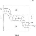
- FIG. 1 is an example of part 100 that is formed by PBF shown in a cut-away side view. While the following describes an EBM process, the removal methods are applicable to all PBF created pieces where powder needs to be removed from internal passages.
- the part 100 includes first and second portions 102, 104 separated by an internal passage 106. As the part 100 is formed, metallic power is first layered down and then sintered. The portions of the part 100 that are to become part of the final product are then exposed to an electron beam to convert the sintered powder to a hard metal object. However, the portions of the part that are not exposed to the electron beam are still sintered, just not fully hardened by the electron beam.
- the passage 106 may be filled with sintered material 108. That is, the portions 102, 104 are metal pieces formed by exposing the sintered powder to an electron beam to form the fully hardened metal. Portions that are not exposed remain as partially hardened sintered material as illustrated by sintered material 108. Removal of this material to open, for example, passage 106 may be difficult, especially when the passage is not a straight or varies in size.
- a wire 110 is formed through the passage 106.
- the wire 110 is formed in the same manner as the portions 102, 104. That is, as each level of the part 100 is formed, a small portion of the otherwise sintered only section (e.g., material 108) is exposed to the electron beam to form a continuous wire 110 through it.
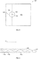
- FIG. 2 shows a top view of the part taken along line A-A from FIG. 1 .
- the portions 102, 104 have been exposed to the electron beam to fully harden them. So too has the wire 110.
- portions 102, 104 and wire 110 are in the same state of processing and are fully hardened metal.
- the passage 106 is shown as including sintered material 108 that has not been exposed to an electron beam. This is the material that needs to be removed in order to allow material to pass through passage 106. For example, if the part 100 is a manifold, passage 106 would need material 108 removed in order to allow fluids to pass through it.
- the wire 110 may be coupled to a transducer 112.
- the transducer 112 is an ultrasonic transducer in one embodiment.
- the transducer 112 provides an ultrasonic input to the wire 100 which causes the sintered material 110 to more easily be removed.
- FIG. 3 shows an alternative embodiment.
- a passage 106 is formed that includes sintered material (not shown). Portions of sintered material are exposed to form multiple sinusoidal wires 110a, 110b, 110c.
- the number of wires can be varied from 1 to any number and the wires can be either straight or sinusoidal.
- Using sinusoidal wire shapes may allow for more ultrasonic energy from the transducer 112 to be contact the sintered material in the passage 106. Further, as the wires 110 are pulled out (for example, in direction C) the increased surface area of additional wires may remove more powder.
- FIG. 4 shows yet another embodiment.
- the passage 106 is formed to include wire 110 a cleaning element 120.
- the cleaning element 120 is formed of the same material as the wire in one embodiment. As the wire 100 is removed (direction C) the cleaning element 120 may aid in powder removal. The particular shape of the cleaning element 120 may be varied from that shown in FIG. 4 . Also, more cleaning elements 120 may be provided. In general, the cleaning element 120 has a larger cross-section than the wire 110. In another embodiment, one or more optional additional cleaning elements 140 may be added to the wire 110. One or more of the additional elements 140 may be of a different size or shape than cleaning element 120.
- nested cleaning elements 220 may be provided. Each element (e.g., 220a, 220b) may be attached to an individual wire 110a, 110b, respectively. As illustrated, a first cleaning element 220a is attached to a first wire 110a and a second cleaning element 220b is attached to a second wire 110b. In this configuration, the first wire 110a passes through a hole or other passage way (e.g., notch 240) formed in the second cleaning element 220b. This allows the second cleaning element 220b to be removed before the first cleaning element 220a. In this manner, a first amount of powder may be removed and then a second amount (assuming that the second cleaning element 220b is smaller than the first cleaning element 220a). In one embodiment, the wires 110a. 110b may run through different channels to allow them both to work in the illustrated channel 106 and then to work in different channels as they are removed.
- FIG. 6 shows a method according to one embodiment. The method includes several optional steps that may or may not be needed depending on the particular wire/cleaning element combination chosen.
- a plan for part is received.
- the plan may, for example, be a representation of the part or it may be CAD model of the part.
- One or more wires are added to the plan at block 602.
- the added wires are added such that they will be formed in an interior passage(s) of the part.
- optional cleaning elements are added to the plan.
- the part, including the wire(s)/optional cleaning element(s) is formed.
- the part and the wires are formed using electron beam manufacturing as described above.
- a signal is applied to the wires. This signal causes sintered powder to break up or otherwise become easier to remove.
- the signal is an ultrasonic signal in one embodiment.
- the wire (or wires) is removed.
Landscapes
- Engineering & Computer Science (AREA)
- Manufacturing & Machinery (AREA)
- Mechanical Engineering (AREA)
- Physics & Mathematics (AREA)
- Plasma & Fusion (AREA)
- Chemical & Material Sciences (AREA)
- Materials Engineering (AREA)
- Powder Metallurgy (AREA)
- Welding Or Cutting Using Electron Beams (AREA)
Abstract
Description
- This invention relates forming elements or parts and, more particularly, to a method of removing power from parts formed by electron beam melting.
- Powder bed fusion (PBF) methods use either a laser or electron beam to melt and fuse material powder together. Electron beam melting (EBM) is a particular example of a PDF method and is a type of additive manufacturing (AM) for metal parts. In particular, it is a powder bed fusion technique process where an electron beam is used to melting metal powder layer by layer in a vacuum to form a product. One unique aspect of EBM additive manufacturing is that non-melted particles, i.e. those particles not utilized in the final part, are sintered together. The sintering process binds the non-melted particles together providing additional mechanical strength during the build process. The sintered particle is very difficult to remove from more complex structures, particularly those that contain internal features such passages or blind holes. Another type of PDF utilizes a laser. Powder is not sintered but complex geometries may still exist that include powder.
- According to one aspect of the invention, a method for forming a part is disclosed. The method includes: forming a first portion of the part at a first level; forming a second portion of the part at a second level; wherein forming the first and second portions includes exposing the first and second levels to a sintering process and portions of the first and second levels to an electron beam; forming a wire in the passage formed inside the first and second portions by exposing a portion of the passage to the electron beam; applying a signal to the wire to break up sintered material in the passage; and removing the wire.
- According to some aspects of the invention , a method for forming a part includes: forming a first portion of the part at a first level; forming a second portion of the part at a second level; wherein the first and second portions are formed by exposing, respectively, by exposing some of the first level and some of the second level to a laser beam; forming a wire in the passage formed inside the first and second portions by exposing a portion of the passage to the laser beam; applying a signal to the wire to break up sintered material in the passage; and removing the wire.
- The subject matter which is regarded as the invention is particularly pointed out and distinctly claimed in the claims at the conclusion of the specification. The foregoing and other features, and advantages of the invention are apparent from the following detailed description taken in conjunction with the accompanying drawings in which:
-
FIG. 1 is a cut-away side view of a part including powder and a removal wire; -
FIG. 2 is a top view of the part ofFIG. 1 taken along line A-A; -
FIG. 3 depicts one example of a passage with multiple wires formed therein; -
FIG. 4 depicts another embodiment of a wire including a cleaning attachment; -
FIG. 5 shows an alternative embodiment that includes multiple wires and cleaning elements in combination; and -
FIG. 6 is a flow chart of one method of removing powder. - As briefly described above, it is very difficult to remove the dense, sintered powder after completion of the build. Parts with internal features such as passages within a housing have to be specially processed in order to remove dense powder. Powder removal is a step that, for complex parts, will add cost to an additively built part. Embodiments disclosed herein may provide a more efficient or economical solution to removing the dense power.
- The methods disclosed herein may expedite and minimize the amount of time required for powder removal from PBF (including EBM and laser PBF) manufactured parts. In one embodiment, the removal element is formed as a portion of the part itself, used to remove the powder and then discarded. The methods disclosed herein may be especially useful in removing hardened powered in internal surfaces of a part.
-
FIG. 1 is an example ofpart 100 that is formed by PBF shown in a cut-away side view. While the following describes an EBM process, the removal methods are applicable to all PBF created pieces where powder needs to be removed from internal passages. Thepart 100 includes first andsecond portions internal passage 106. As thepart 100 is formed, metallic power is first layered down and then sintered. The portions of thepart 100 that are to become part of the final product are then exposed to an electron beam to convert the sintered powder to a hard metal object. However, the portions of the part that are not exposed to the electron beam are still sintered, just not fully hardened by the electron beam. - In the example in
FIG. 1 , thepassage 106 may be filled withsintered material 108. That is, theportions material 108. Removal of this material to open, for example,passage 106 may be difficult, especially when the passage is not a straight or varies in size. According to one embodiment, as thepart 100 is being formed, awire 110 is formed through thepassage 106. Thewire 110 is formed in the same manner as theportions part 100 is formed, a small portion of the otherwise sintered only section (e.g., material 108) is exposed to the electron beam to form acontinuous wire 110 through it. -
FIG. 2 shows a top view of the part taken along line A-A fromFIG. 1 . Theportions wire 110. Thus,portions wire 110 are in the same state of processing and are fully hardened metal. Thepassage 106 is shown as including sinteredmaterial 108 that has not been exposed to an electron beam. This is the material that needs to be removed in order to allow material to pass throughpassage 106. For example, if thepart 100 is a manifold,passage 106 would needmaterial 108 removed in order to allow fluids to pass through it. - With reference to both
FIGs. 1 and2 , in one embodiment, thewire 110 may be coupled to atransducer 112. Thetransducer 112 is an ultrasonic transducer in one embodiment. In one embodiment, thetransducer 112 provides an ultrasonic input to thewire 100 which causes the sinteredmaterial 110 to more easily be removed. -
FIG. 3 shows an alternative embodiment. Again, apassage 106 is formed that includes sintered material (not shown). Portions of sintered material are exposed to form multiplesinusoidal wires transducer 112 to be contact the sintered material in thepassage 106. Further, as thewires 110 are pulled out (for example, in direction C) the increased surface area of additional wires may remove more powder. -
FIG. 4 shows yet another embodiment. In this embodiment, thepassage 106 is formed to includewire 110 acleaning element 120. Thecleaning element 120 is formed of the same material as the wire in one embodiment. As thewire 100 is removed (direction C) thecleaning element 120 may aid in powder removal. The particular shape of thecleaning element 120 may be varied from that shown inFIG. 4 . Also,more cleaning elements 120 may be provided. In general, thecleaning element 120 has a larger cross-section than thewire 110. In another embodiment, one or more optionaladditional cleaning elements 140 may be added to thewire 110. One or more of theadditional elements 140 may be of a different size or shape than cleaningelement 120. - In yet another embodiment, nested cleaning elements 220 may be provided. Each element (e.g., 220a, 220b) may be attached to an
individual wire first cleaning element 220a is attached to afirst wire 110a and asecond cleaning element 220b is attached to asecond wire 110b. In this configuration, thefirst wire 110a passes through a hole or other passage way (e.g., notch 240) formed in thesecond cleaning element 220b. This allows thesecond cleaning element 220b to be removed before thefirst cleaning element 220a. In this manner, a first amount of powder may be removed and then a second amount (assuming that thesecond cleaning element 220b is smaller than thefirst cleaning element 220a). In one embodiment, thewires 110a. 110b may run through different channels to allow them both to work in the illustratedchannel 106 and then to work in different channels as they are removed. -
FIG. 6 shows a method according to one embodiment. The method includes several optional steps that may or may not be needed depending on the particular wire/cleaning element combination chosen. - At block 600 a plan for part is received. The plan may, for example, be a representation of the part or it may be CAD model of the part. One or more wires are added to the plan at
block 602. The added wires are added such that they will be formed in an interior passage(s) of the part. Atblock 604 optional cleaning elements are added to the plan. Atblock 606 the part, including the wire(s)/optional cleaning element(s), is formed. The part and the wires are formed using electron beam manufacturing as described above. At block 608 a signal is applied to the wires. This signal causes sintered powder to break up or otherwise become easier to remove. The signal is an ultrasonic signal in one embodiment. Atblock 610 the wire (or wires) is removed. - While the invention has been described in detail in connection with only a limited number of embodiments, it should be readily understood that the invention is not limited to such disclosed embodiments. Rather, the invention can be modified to incorporate any number of variations, alterations or substitutions, but which are commensurate with the scope of the invention. Additionally, while various embodiments of the invention have been described, it is to be understood that aspects of the invention may include only some of the described embodiments. Accordingly, the invention is not to be seen as limited by the foregoing description, but is only limited by the scope of the appended claims.
Claims (15)
- A method for forming a part, the method comprising:forming a first portion (102) of the part at a first level;forming a second portion (104) of the part at a second level;wherein forming the first and second portions (102, 104) includes exposing the first and second levels to a sintering process and portions of the first and second levels to an electron beam;forming a wire (110) in a passage (106) formed inside the first and second portions (102, 104) by exposing a portion of the passage to the electron beam;applying a signal to the wire (110) to break up sintered material in the passage (106); andremoving the wire (110).
- The method of claim 1, wherein the first and second levels are formed from a sintered metallic powder.
- The method of claim 2, wherein forming the at least one wire (110) includes forming a first wire and a second wire.
- The method of any of claims 2 or 3, wherein the at least one wire (110) has a sinusoidal shape.
- The method of claims 2-4, wherein forming the at least one wire (110) includes forming a cleaning element (220) on the wire (110).
- The method of claim 5, wherein the cleaning element has a larger cross-section than the wire.
- The method of claim 6, further, comprising:forming a secondary wire (110b);forming a secondary cleaning element (220b) on the second wire (110b);applying a signal to the secondary wire (110b); andremoving the secondary wire (110b) and the secondary cleaning element (220b).
- The method of claim 7, wherein the wire passes at least partially through the secondary cleaning element (220b).
- The method of any preceding claim, wherein the signal is an ultrasonic signal.
- A method for forming a part (100), the method comprising:forming a first portion (102) of the part at a first level;forming a second portion (104) of the part at a second level;wherein the first and second portions (102, 104) are formed by exposing, respectively, by exposing some of the first level and some of the second level to a laser beam;forming a wire in a passage (106) formed inside the first and second portions (102, 104) by exposing a portion of the passage to the laser beam;applying a signal to the wire (110) to break up sintered material in the passage (106); andremoving the wire (110).
- The method of claim 10, wherein the first and second levels are formed from a powder.
- The method of claim 11, wherein forming the at least one wire (110) includes forming a first wire and a second wire.
- The method of claims 11 or 12, wherein the at least one wire (110) has a sinusoidal shape.
- The method of any of claims 11-13, wherein forming the at least one wire (110) includes forming a cleaning element (220) on the wire.
- The method of claim 14, wherein the cleaning element (220) has a larger cross-section than the wire.
Applications Claiming Priority (1)
| Application Number | Priority Date | Filing Date | Title |
|---|---|---|---|
| US14/660,545 US9773586B2 (en) | 2015-03-17 | 2015-03-17 | Powered removal for element formed by electron beam melting |
Publications (3)
| Publication Number | Publication Date |
|---|---|
| EP3069805A2 true EP3069805A2 (en) | 2016-09-21 |
| EP3069805A3 EP3069805A3 (en) | 2016-10-12 |
| EP3069805B1 EP3069805B1 (en) | 2019-06-19 |
Family
ID=55699364
Family Applications (1)
| Application Number | Title | Priority Date | Filing Date |
|---|---|---|---|
| EP16160748.6A Active EP3069805B1 (en) | 2015-03-17 | 2016-03-16 | Powered removal for element formed by electron beam melting inside a cavity of an object simultaneously additively formed by electron beam melting |
Country Status (3)
| Country | Link |
|---|---|
| US (1) | US9773586B2 (en) |
| EP (1) | EP3069805B1 (en) |
| JP (1) | JP6695715B2 (en) |
Cited By (9)
| Publication number | Priority date | Publication date | Assignee | Title |
|---|---|---|---|---|
| EP3153256A1 (en) * | 2015-10-05 | 2017-04-12 | United Technologies Corporation | Additive manufactured conglomerated powder removal from internal passages |
| EP3192599A1 (en) * | 2016-01-13 | 2017-07-19 | United Technologies Corporation | Method for removing partially sintered powder from internal passages in electron beam additive manufactured parts |
| EP3199270A1 (en) * | 2016-02-01 | 2017-08-02 | United Technologies Corporation | Additive manufactured conglomerated powder removal from internal passages with co-built agitation solids |
| EP3199269A1 (en) * | 2016-02-01 | 2017-08-02 | United Technologies Corporation | Additive manufactured conglomerated powder removal from internal passages with co-built ultrasonic horns |
| EP3219417A1 (en) * | 2016-03-18 | 2017-09-20 | United Technologies Corporation | Sacrificial core for conglomerated powder removal |
| EP3219418A1 (en) * | 2016-03-18 | 2017-09-20 | United Technologies Corporation | Sacrificial core for conglomerated powder removal |
| GB2539092B (en) * | 2015-06-03 | 2020-02-19 | Rolls Royce Plc | Manufacture of component with cavity |
| WO2020065650A1 (en) * | 2018-09-26 | 2020-04-02 | Stratasys Ltd. | Automated 3d-printing of hollow objects |
| DE102018125263B4 (en) | 2018-10-12 | 2025-01-30 | Volkswagen Aktiengesellschaft | Method and device for cleaning components manufactured in a powder bed |
Families Citing this family (2)
| Publication number | Priority date | Publication date | Assignee | Title |
|---|---|---|---|---|
| US12251884B2 (en) * | 2017-04-28 | 2025-03-18 | Divergent Technologies, Inc. | Support structures in additive manufacturing |
| US20190201982A1 (en) | 2018-01-03 | 2019-07-04 | General Electric Company | Systems and methods for removing build material from additively manufactured parts |
Family Cites Families (9)
| Publication number | Priority date | Publication date | Assignee | Title |
|---|---|---|---|---|
| US4104445A (en) * | 1975-10-20 | 1978-08-01 | Monsanto Company | Method for making steel wire |
| US4386970A (en) * | 1980-10-20 | 1983-06-07 | Kabushiki Kaisha Kobe Seiko Sho | Production method of compound-type superconducting wire |
| GB2110135A (en) * | 1981-11-03 | 1983-06-15 | Robert Bernard Cummins | Making metal wire from powder |
| JP3893992B2 (en) | 2002-01-31 | 2007-03-14 | 松下電工株式会社 | Method for producing photomolding |
| US7521652B2 (en) * | 2004-12-07 | 2009-04-21 | 3D Systems, Inc. | Controlled cooling methods and apparatus for laser sintering part-cake |
| US8828311B2 (en) | 2009-05-15 | 2014-09-09 | Board Of Regents, The University Of Texas System | Reticulated mesh arrays and dissimilar array monoliths by additive layered manufacturing using electron and laser beam melting |
| JPWO2013137283A1 (en) | 2012-03-16 | 2015-08-03 | パナソニック株式会社 | Manufacturing method of three-dimensional shaped object and three-dimensional shaped object |
| GB2517490B (en) | 2013-08-23 | 2015-08-05 | Univ Montfort | Additive manufacturing methods |
| GB201502087D0 (en) | 2015-02-09 | 2015-03-25 | Rolls Royce Plc | A method for the production on a three-dimensional product |
-
2015
- 2015-03-17 US US14/660,545 patent/US9773586B2/en active Active
-
2016
- 2016-03-16 EP EP16160748.6A patent/EP3069805B1/en active Active
- 2016-03-17 JP JP2016053195A patent/JP6695715B2/en active Active
Non-Patent Citations (1)
| Title |
|---|
| None |
Cited By (16)
| Publication number | Priority date | Publication date | Assignee | Title |
|---|---|---|---|---|
| GB2539092B (en) * | 2015-06-03 | 2020-02-19 | Rolls Royce Plc | Manufacture of component with cavity |
| EP3153256A1 (en) * | 2015-10-05 | 2017-04-12 | United Technologies Corporation | Additive manufactured conglomerated powder removal from internal passages |
| US11312064B2 (en) | 2015-10-05 | 2022-04-26 | Raytheon Technologies Corporation | Additive manufactured conglomerated powder removal from internal passages |
| US10786966B2 (en) | 2015-10-05 | 2020-09-29 | Raytheon Technologies Corporation | Additive manufactured conglomerated powder removal from internal passages |
| EP3192599A1 (en) * | 2016-01-13 | 2017-07-19 | United Technologies Corporation | Method for removing partially sintered powder from internal passages in electron beam additive manufactured parts |
| US10940510B2 (en) | 2016-02-01 | 2021-03-09 | Raytheon Technologies Corporation | Additive manufactured conglomerated powder removal from internal passages with co-built ultrasonic horns |
| EP3199270A1 (en) * | 2016-02-01 | 2017-08-02 | United Technologies Corporation | Additive manufactured conglomerated powder removal from internal passages with co-built agitation solids |
| EP3199269A1 (en) * | 2016-02-01 | 2017-08-02 | United Technologies Corporation | Additive manufactured conglomerated powder removal from internal passages with co-built ultrasonic horns |
| US11597014B2 (en) | 2016-02-01 | 2023-03-07 | Raytheon Technologies Corporation | Additive manufactured conglomerated powder removal from internal passages |
| EP3219417A1 (en) * | 2016-03-18 | 2017-09-20 | United Technologies Corporation | Sacrificial core for conglomerated powder removal |
| EP3219418A1 (en) * | 2016-03-18 | 2017-09-20 | United Technologies Corporation | Sacrificial core for conglomerated powder removal |
| WO2020065650A1 (en) * | 2018-09-26 | 2020-04-02 | Stratasys Ltd. | Automated 3d-printing of hollow objects |
| US11840014B2 (en) | 2018-09-26 | 2023-12-12 | Stratasys Ltd. | Automated 3D-printing of hollow objects |
| IL281694B1 (en) * | 2018-09-26 | 2025-06-01 | Stratasys Ltd | Automated 3D printing of hollow objects |
| IL281694B2 (en) * | 2018-09-26 | 2025-10-01 | Stratasys Ltd | Automated 3d-printing of hollow objects |
| DE102018125263B4 (en) | 2018-10-12 | 2025-01-30 | Volkswagen Aktiengesellschaft | Method and device for cleaning components manufactured in a powder bed |
Also Published As
| Publication number | Publication date |
|---|---|
| EP3069805B1 (en) | 2019-06-19 |
| US20160271697A1 (en) | 2016-09-22 |
| EP3069805A3 (en) | 2016-10-12 |
| JP2016176145A (en) | 2016-10-06 |
| JP6695715B2 (en) | 2020-05-20 |
| US9773586B2 (en) | 2017-09-26 |
Similar Documents
| Publication | Publication Date | Title |
|---|---|---|
| EP3069805B1 (en) | Powered removal for element formed by electron beam melting inside a cavity of an object simultaneously additively formed by electron beam melting | |
| EP3144081B1 (en) | Powder removal for element formed by powder bed fusion additive manufacturing processes | |
| Jelali | An overview of control performance assessment technology and industrial applications | |
| CN107405709B (en) | Method for manufacturing a support structure for supporting a three-dimensional object to be generatively constructed | |
| GB2517490A (en) | Additive manufacturing methods | |
| EP3363563B1 (en) | Additive manufacturing method to produce a heat exchanger | |
| EP3178588A2 (en) | Adjusting process parameters of an additive mahufacturing process to reduce conglomerated powder in cavity | |
| DE10229952A1 (en) | Metallic workpiece and method for producing a metallic workpiece | |
| JP2017511842A (en) | Forming tool, method for producing green body and method for using forming tool | |
| EP1348506A3 (en) | Method of making sintered object by selective laser sintering | |
| EP3219418B1 (en) | Sacrificial core for conglomerated powder removal | |
| WO2013160198A1 (en) | Method for manufacturing a component having an overhang by layer-wise buildup | |
| DE102015210744A1 (en) | Method for manufacturing a turbine blade | |
| EP2666613A1 (en) | Invention related to auxiliary structures for the production of components by means of generative or additive methods | |
| US20170197362A1 (en) | Sacrificial core for conglomerated powder removal | |
| WO2017054799A1 (en) | Composite body having at least one functional component, and a method for producing said composite body | |
| JPWO2016051778A1 (en) | Injection mold | |
| US20180029123A1 (en) | Removable support package for additive manufacture | |
| EP2792436A2 (en) | Integrally formed stiffener | |
| JP6417586B2 (en) | Modeling method and model | |
| EP3219417A1 (en) | Sacrificial core for conglomerated powder removal | |
| EP3233337B1 (en) | Laser sintering method for manufacturing a tread molding element | |
| US20170197364A1 (en) | Sacrificial core for conglomerated powder removal | |
| US11813689B2 (en) | Method for producing a solder deposit, and solder deposit | |
| DE102013002242A1 (en) | Producing component, which flows through and around medium, preferably producing housing component, preferably producing valve component, comprises producing component in three dimensions by selective melting of raw material |
Legal Events
| Date | Code | Title | Description |
|---|---|---|---|
| PUAI | Public reference made under article 153(3) epc to a published international application that has entered the european phase |
Free format text: ORIGINAL CODE: 0009012 |
|
| PUAL | Search report despatched |
Free format text: ORIGINAL CODE: 0009013 |
|
| AK | Designated contracting states |
Kind code of ref document: A2 Designated state(s): AL AT BE BG CH CY CZ DE DK EE ES FI FR GB GR HR HU IE IS IT LI LT LU LV MC MK MT NL NO PL PT RO RS SE SI SK SM TR |
|
| AX | Request for extension of the european patent |
Extension state: BA ME |
|
| AK | Designated contracting states |
Kind code of ref document: A3 Designated state(s): AL AT BE BG CH CY CZ DE DK EE ES FI FR GB GR HR HU IE IS IT LI LT LU LV MC MK MT NL NO PL PT RO RS SE SI SK SM TR |
|
| AX | Request for extension of the european patent |
Extension state: BA ME |
|
| RIC1 | Information provided on ipc code assigned before grant |
Ipc: B22F 3/105 20060101AFI20160902BHEP Ipc: B22F 3/24 20060101ALI20160902BHEP |
|
| STAA | Information on the status of an ep patent application or granted ep patent |
Free format text: STATUS: REQUEST FOR EXAMINATION WAS MADE |
|
| 17P | Request for examination filed |
Effective date: 20170405 |
|
| RBV | Designated contracting states (corrected) |
Designated state(s): AL AT BE BG CH CY CZ DE DK EE ES FI FR GB GR HR HU IE IS IT LI LT LU LV MC MK MT NL NO PL PT RO RS SE SI SK SM TR |
|
| REG | Reference to a national code |
Ref country code: DE Ref legal event code: R079 Ref document number: 602016015388 Country of ref document: DE Free format text: PREVIOUS MAIN CLASS: B22F0003105000 Ipc: B22F0005100000 |
|
| GRAP | Despatch of communication of intention to grant a patent |
Free format text: ORIGINAL CODE: EPIDOSNIGR1 |
|
| STAA | Information on the status of an ep patent application or granted ep patent |
Free format text: STATUS: GRANT OF PATENT IS INTENDED |
|
| RIC1 | Information provided on ipc code assigned before grant |
Ipc: B22F 3/24 20060101ALI20181218BHEP Ipc: B33Y 10/00 20150101ALI20181218BHEP Ipc: B33Y 40/00 20150101ALI20181218BHEP Ipc: B22F 5/10 20060101AFI20181218BHEP Ipc: B22F 3/105 20060101ALI20181218BHEP Ipc: B23K 26/34 20140101ALI20181218BHEP |
|
| INTG | Intention to grant announced |
Effective date: 20190123 |
|
| RAP1 | Party data changed (applicant data changed or rights of an application transferred) |
Owner name: HAMILTON SUNDSTRAND CORPORATION |
|
| GRAS | Grant fee paid |
Free format text: ORIGINAL CODE: EPIDOSNIGR3 |
|
| GRAA | (expected) grant |
Free format text: ORIGINAL CODE: 0009210 |
|
| STAA | Information on the status of an ep patent application or granted ep patent |
Free format text: STATUS: THE PATENT HAS BEEN GRANTED |
|
| AK | Designated contracting states |
Kind code of ref document: B1 Designated state(s): AL AT BE BG CH CY CZ DE DK EE ES FI FR GB GR HR HU IE IS IT LI LT LU LV MC MK MT NL NO PL PT RO RS SE SI SK SM TR |
|
| REG | Reference to a national code |
Ref country code: GB Ref legal event code: FG4D |
|
| REG | Reference to a national code |
Ref country code: CH Ref legal event code: EP |
|
| REG | Reference to a national code |
Ref country code: IE Ref legal event code: FG4D |
|
| REG | Reference to a national code |
Ref country code: DE Ref legal event code: R096 Ref document number: 602016015388 Country of ref document: DE |
|
| REG | Reference to a national code |
Ref country code: AT Ref legal event code: REF Ref document number: 1144849 Country of ref document: AT Kind code of ref document: T Effective date: 20190715 |
|
| REG | Reference to a national code |
Ref country code: NL Ref legal event code: MP Effective date: 20190619 |
|
| PG25 | Lapsed in a contracting state [announced via postgrant information from national office to epo] |
Ref country code: HR Free format text: LAPSE BECAUSE OF FAILURE TO SUBMIT A TRANSLATION OF THE DESCRIPTION OR TO PAY THE FEE WITHIN THE PRESCRIBED TIME-LIMIT Effective date: 20190619 Ref country code: LT Free format text: LAPSE BECAUSE OF FAILURE TO SUBMIT A TRANSLATION OF THE DESCRIPTION OR TO PAY THE FEE WITHIN THE PRESCRIBED TIME-LIMIT Effective date: 20190619 Ref country code: FI Free format text: LAPSE BECAUSE OF FAILURE TO SUBMIT A TRANSLATION OF THE DESCRIPTION OR TO PAY THE FEE WITHIN THE PRESCRIBED TIME-LIMIT Effective date: 20190619 Ref country code: NO Free format text: LAPSE BECAUSE OF FAILURE TO SUBMIT A TRANSLATION OF THE DESCRIPTION OR TO PAY THE FEE WITHIN THE PRESCRIBED TIME-LIMIT Effective date: 20190919 Ref country code: SE Free format text: LAPSE BECAUSE OF FAILURE TO SUBMIT A TRANSLATION OF THE DESCRIPTION OR TO PAY THE FEE WITHIN THE PRESCRIBED TIME-LIMIT Effective date: 20190619 Ref country code: AL Free format text: LAPSE BECAUSE OF FAILURE TO SUBMIT A TRANSLATION OF THE DESCRIPTION OR TO PAY THE FEE WITHIN THE PRESCRIBED TIME-LIMIT Effective date: 20190619 |
|
| REG | Reference to a national code |
Ref country code: LT Ref legal event code: MG4D |
|
| PG25 | Lapsed in a contracting state [announced via postgrant information from national office to epo] |
Ref country code: BG Free format text: LAPSE BECAUSE OF FAILURE TO SUBMIT A TRANSLATION OF THE DESCRIPTION OR TO PAY THE FEE WITHIN THE PRESCRIBED TIME-LIMIT Effective date: 20190919 Ref country code: LV Free format text: LAPSE BECAUSE OF FAILURE TO SUBMIT A TRANSLATION OF THE DESCRIPTION OR TO PAY THE FEE WITHIN THE PRESCRIBED TIME-LIMIT Effective date: 20190619 Ref country code: RS Free format text: LAPSE BECAUSE OF FAILURE TO SUBMIT A TRANSLATION OF THE DESCRIPTION OR TO PAY THE FEE WITHIN THE PRESCRIBED TIME-LIMIT Effective date: 20190619 Ref country code: GR Free format text: LAPSE BECAUSE OF FAILURE TO SUBMIT A TRANSLATION OF THE DESCRIPTION OR TO PAY THE FEE WITHIN THE PRESCRIBED TIME-LIMIT Effective date: 20190920 |
|
| REG | Reference to a national code |
Ref country code: AT Ref legal event code: MK05 Ref document number: 1144849 Country of ref document: AT Kind code of ref document: T Effective date: 20190619 |
|
| PG25 | Lapsed in a contracting state [announced via postgrant information from national office to epo] |
Ref country code: PT Free format text: LAPSE BECAUSE OF FAILURE TO SUBMIT A TRANSLATION OF THE DESCRIPTION OR TO PAY THE FEE WITHIN THE PRESCRIBED TIME-LIMIT Effective date: 20191021 Ref country code: EE Free format text: LAPSE BECAUSE OF FAILURE TO SUBMIT A TRANSLATION OF THE DESCRIPTION OR TO PAY THE FEE WITHIN THE PRESCRIBED TIME-LIMIT Effective date: 20190619 Ref country code: NL Free format text: LAPSE BECAUSE OF FAILURE TO SUBMIT A TRANSLATION OF THE DESCRIPTION OR TO PAY THE FEE WITHIN THE PRESCRIBED TIME-LIMIT Effective date: 20190619 Ref country code: SK Free format text: LAPSE BECAUSE OF FAILURE TO SUBMIT A TRANSLATION OF THE DESCRIPTION OR TO PAY THE FEE WITHIN THE PRESCRIBED TIME-LIMIT Effective date: 20190619 Ref country code: CZ Free format text: LAPSE BECAUSE OF FAILURE TO SUBMIT A TRANSLATION OF THE DESCRIPTION OR TO PAY THE FEE WITHIN THE PRESCRIBED TIME-LIMIT Effective date: 20190619 Ref country code: RO Free format text: LAPSE BECAUSE OF FAILURE TO SUBMIT A TRANSLATION OF THE DESCRIPTION OR TO PAY THE FEE WITHIN THE PRESCRIBED TIME-LIMIT Effective date: 20190619 Ref country code: AT Free format text: LAPSE BECAUSE OF FAILURE TO SUBMIT A TRANSLATION OF THE DESCRIPTION OR TO PAY THE FEE WITHIN THE PRESCRIBED TIME-LIMIT Effective date: 20190619 |
|
| PG25 | Lapsed in a contracting state [announced via postgrant information from national office to epo] |
Ref country code: IS Free format text: LAPSE BECAUSE OF FAILURE TO SUBMIT A TRANSLATION OF THE DESCRIPTION OR TO PAY THE FEE WITHIN THE PRESCRIBED TIME-LIMIT Effective date: 20191019 Ref country code: SM Free format text: LAPSE BECAUSE OF FAILURE TO SUBMIT A TRANSLATION OF THE DESCRIPTION OR TO PAY THE FEE WITHIN THE PRESCRIBED TIME-LIMIT Effective date: 20190619 Ref country code: ES Free format text: LAPSE BECAUSE OF FAILURE TO SUBMIT A TRANSLATION OF THE DESCRIPTION OR TO PAY THE FEE WITHIN THE PRESCRIBED TIME-LIMIT Effective date: 20190619 |
|
| PG25 | Lapsed in a contracting state [announced via postgrant information from national office to epo] |
Ref country code: TR Free format text: LAPSE BECAUSE OF FAILURE TO SUBMIT A TRANSLATION OF THE DESCRIPTION OR TO PAY THE FEE WITHIN THE PRESCRIBED TIME-LIMIT Effective date: 20190619 |
|
| PG25 | Lapsed in a contracting state [announced via postgrant information from national office to epo] |
Ref country code: DK Free format text: LAPSE BECAUSE OF FAILURE TO SUBMIT A TRANSLATION OF THE DESCRIPTION OR TO PAY THE FEE WITHIN THE PRESCRIBED TIME-LIMIT Effective date: 20190619 Ref country code: PL Free format text: LAPSE BECAUSE OF FAILURE TO SUBMIT A TRANSLATION OF THE DESCRIPTION OR TO PAY THE FEE WITHIN THE PRESCRIBED TIME-LIMIT Effective date: 20190619 |
|
| PG25 | Lapsed in a contracting state [announced via postgrant information from national office to epo] |
Ref country code: IS Free format text: LAPSE BECAUSE OF FAILURE TO SUBMIT A TRANSLATION OF THE DESCRIPTION OR TO PAY THE FEE WITHIN THE PRESCRIBED TIME-LIMIT Effective date: 20200224 |
|
| REG | Reference to a national code |
Ref country code: DE Ref legal event code: R097 Ref document number: 602016015388 Country of ref document: DE |
|
| PLBE | No opposition filed within time limit |
Free format text: ORIGINAL CODE: 0009261 |
|
| STAA | Information on the status of an ep patent application or granted ep patent |
Free format text: STATUS: NO OPPOSITION FILED WITHIN TIME LIMIT |
|
| PG2D | Information on lapse in contracting state deleted |
Ref country code: IS |
|
| 26N | No opposition filed |
Effective date: 20200603 |
|
| PG25 | Lapsed in a contracting state [announced via postgrant information from national office to epo] |
Ref country code: SI Free format text: LAPSE BECAUSE OF FAILURE TO SUBMIT A TRANSLATION OF THE DESCRIPTION OR TO PAY THE FEE WITHIN THE PRESCRIBED TIME-LIMIT Effective date: 20190619 |
|
| PG25 | Lapsed in a contracting state [announced via postgrant information from national office to epo] |
Ref country code: MC Free format text: LAPSE BECAUSE OF FAILURE TO SUBMIT A TRANSLATION OF THE DESCRIPTION OR TO PAY THE FEE WITHIN THE PRESCRIBED TIME-LIMIT Effective date: 20190619 |
|
| REG | Reference to a national code |
Ref country code: CH Ref legal event code: PL |
|
| REG | Reference to a national code |
Ref country code: BE Ref legal event code: MM Effective date: 20200331 |
|
| PG25 | Lapsed in a contracting state [announced via postgrant information from national office to epo] |
Ref country code: LU Free format text: LAPSE BECAUSE OF NON-PAYMENT OF DUE FEES Effective date: 20200316 |
|
| PG25 | Lapsed in a contracting state [announced via postgrant information from national office to epo] |
Ref country code: LI Free format text: LAPSE BECAUSE OF NON-PAYMENT OF DUE FEES Effective date: 20200331 Ref country code: IE Free format text: LAPSE BECAUSE OF NON-PAYMENT OF DUE FEES Effective date: 20200316 Ref country code: CH Free format text: LAPSE BECAUSE OF NON-PAYMENT OF DUE FEES Effective date: 20200331 Ref country code: FR Free format text: LAPSE BECAUSE OF NON-PAYMENT OF DUE FEES Effective date: 20200331 |
|
| PG25 | Lapsed in a contracting state [announced via postgrant information from national office to epo] |
Ref country code: BE Free format text: LAPSE BECAUSE OF NON-PAYMENT OF DUE FEES Effective date: 20200331 |
|
| PG25 | Lapsed in a contracting state [announced via postgrant information from national office to epo] |
Ref country code: MT Free format text: LAPSE BECAUSE OF FAILURE TO SUBMIT A TRANSLATION OF THE DESCRIPTION OR TO PAY THE FEE WITHIN THE PRESCRIBED TIME-LIMIT Effective date: 20190619 Ref country code: CY Free format text: LAPSE BECAUSE OF FAILURE TO SUBMIT A TRANSLATION OF THE DESCRIPTION OR TO PAY THE FEE WITHIN THE PRESCRIBED TIME-LIMIT Effective date: 20190619 |
|
| PG25 | Lapsed in a contracting state [announced via postgrant information from national office to epo] |
Ref country code: MK Free format text: LAPSE BECAUSE OF FAILURE TO SUBMIT A TRANSLATION OF THE DESCRIPTION OR TO PAY THE FEE WITHIN THE PRESCRIBED TIME-LIMIT Effective date: 20190619 |
|
| P01 | Opt-out of the competence of the unified patent court (upc) registered |
Effective date: 20230522 |
|
| PGFP | Annual fee paid to national office [announced via postgrant information from national office to epo] |
Ref country code: GB Payment date: 20260219 Year of fee payment: 11 |
|
| PGFP | Annual fee paid to national office [announced via postgrant information from national office to epo] |
Ref country code: DE Payment date: 20260219 Year of fee payment: 11 |
|
| PGFP | Annual fee paid to national office [announced via postgrant information from national office to epo] |
Ref country code: IT Payment date: 20260219 Year of fee payment: 11 |