EP3069695A1 - An endograft introducer assembly having a transfer sheath - Google Patents
An endograft introducer assembly having a transfer sheath Download PDFInfo
- Publication number
- EP3069695A1 EP3069695A1 EP16275001.2A EP16275001A EP3069695A1 EP 3069695 A1 EP3069695 A1 EP 3069695A1 EP 16275001 A EP16275001 A EP 16275001A EP 3069695 A1 EP3069695 A1 EP 3069695A1
- Authority
- EP
- European Patent Office
- Prior art keywords
- stopper
- transfer sheath
- assembly
- sheath
- distal
- Prior art date
- Legal status (The legal status is an assumption and is not a legal conclusion. Google has not performed a legal analysis and makes no representation as to the accuracy of the status listed.)
- Granted
Links
Images



Classifications
-
- A—HUMAN NECESSITIES
- A61—MEDICAL OR VETERINARY SCIENCE; HYGIENE
- A61F—FILTERS IMPLANTABLE INTO BLOOD VESSELS; PROSTHESES; DEVICES PROVIDING PATENCY TO, OR PREVENTING COLLAPSING OF, TUBULAR STRUCTURES OF THE BODY, e.g. STENTS; ORTHOPAEDIC, NURSING OR CONTRACEPTIVE DEVICES; FOMENTATION; TREATMENT OR PROTECTION OF EYES OR EARS; BANDAGES, DRESSINGS OR ABSORBENT PADS; FIRST-AID KITS
- A61F2/00—Filters implantable into blood vessels; Prostheses, i.e. artificial substitutes or replacements for parts of the body; Appliances for connecting them with the body; Devices providing patency to, or preventing collapsing of, tubular structures of the body, e.g. stents
- A61F2/95—Instruments specially adapted for placement or removal of stents or stent-grafts
- A61F2/962—Instruments specially adapted for placement or removal of stents or stent-grafts having an outer sleeve
- A61F2/966—Instruments specially adapted for placement or removal of stents or stent-grafts having an outer sleeve with relative longitudinal movement between outer sleeve and prosthesis, e.g. using a push rod
-
- A—HUMAN NECESSITIES
- A61—MEDICAL OR VETERINARY SCIENCE; HYGIENE
- A61F—FILTERS IMPLANTABLE INTO BLOOD VESSELS; PROSTHESES; DEVICES PROVIDING PATENCY TO, OR PREVENTING COLLAPSING OF, TUBULAR STRUCTURES OF THE BODY, e.g. STENTS; ORTHOPAEDIC, NURSING OR CONTRACEPTIVE DEVICES; FOMENTATION; TREATMENT OR PROTECTION OF EYES OR EARS; BANDAGES, DRESSINGS OR ABSORBENT PADS; FIRST-AID KITS
- A61F2/00—Filters implantable into blood vessels; Prostheses, i.e. artificial substitutes or replacements for parts of the body; Appliances for connecting them with the body; Devices providing patency to, or preventing collapsing of, tubular structures of the body, e.g. stents
- A61F2/95—Instruments specially adapted for placement or removal of stents or stent-grafts
- A61F2/962—Instruments specially adapted for placement or removal of stents or stent-grafts having an outer sleeve
- A61F2/97—Instruments specially adapted for placement or removal of stents or stent-grafts having an outer sleeve the outer sleeve being splittable
-
- A—HUMAN NECESSITIES
- A61—MEDICAL OR VETERINARY SCIENCE; HYGIENE
- A61F—FILTERS IMPLANTABLE INTO BLOOD VESSELS; PROSTHESES; DEVICES PROVIDING PATENCY TO, OR PREVENTING COLLAPSING OF, TUBULAR STRUCTURES OF THE BODY, e.g. STENTS; ORTHOPAEDIC, NURSING OR CONTRACEPTIVE DEVICES; FOMENTATION; TREATMENT OR PROTECTION OF EYES OR EARS; BANDAGES, DRESSINGS OR ABSORBENT PADS; FIRST-AID KITS
- A61F2250/00—Special features of prostheses classified in groups A61F2/00 - A61F2/26 or A61F2/82 or A61F9/00 or A61F11/00 or subgroups thereof
- A61F2250/0058—Additional features; Implant or prostheses properties not otherwise provided for
- A61F2250/0071—Additional features; Implant or prostheses properties not otherwise provided for breakable or frangible
Definitions
- the invention relates to medical devices and more particularly to a medical device used for deployment of an intraluminal graft or stent graft, otherwise referred to as an introducer or a stent graft introducer.
- this invention relates to an endograft introducer assembly having a transfer sheath.
- a deployment device In the deployment of a graft, or stent graft, into the human or animal body via intraluminal techniques, a deployment device is used to introduce the stent graft into a lumen of the body and, after the stent graft has been deployed and expanded within the lumen, the introducer assembly is retracted.
- a main sheath assembly is required to be deployed into the vasculature independently of the graft.
- a graft which is pre-compressed into a temporary tube or transfer tube is transferred into a main sheath of the main sheath assembly.
- distal with respect to a portion of the aorta, a deployment device or an endograft means the end of the aorta, deployment device or endograft further away in the direction of blood flow away from the heart and the term proximal means the portion of the aorta, deployment device or end of the endograft nearer to the heart.
- proximal means the portion of the aorta, deployment device or end of the endograft nearer to the heart.
- an endograft introducer assembly comprising:
- Preferred embodiments of the invention address the problem of having to deploy a main sheath assembly into the vasculature independently of a graft, as described hereinbefore, or at least provide the practitioner in the field with a useful alternative device.
- the stopper has a second length, the second length less than the first length.
- the distal portion of the stopper comprises a transfer sheath receiving portion having a receiving outer diameter and wherein the stopper surface has a stopper outer diameter, the stopper outer diameter larger than the receiving outer diameter.
- the stopper has a longitudinal split, the split allowing the stopper to flexibly open for lateral movement over the transfer sheath.
- the transfer sheath comprises a return portion at a distal end thereof, the return portion arranged and constructed to prevent relative axial movement between the stopper and the transfer sheath in the at least one direction.
- the stopper has a first longitudinal stiffness and the transfer sheath has a second longitudinal stiffness, the first longitudinal stiffness greater than the second longitudinal stiffness.
- the transfer sheath is frangible so as to allow it to be removed from the pusher without the need to slide over an end of the pusher.
- the transfer sheath comprises a bifurcated end terminating in a pair of gripable tails.
- an assembly comprising:
- the stopper has a second length, the second length less than the first length.
- the distal portion of the stopper comprises a transfer sheath receiving portion having a receiving outer diameter and wherein the stopper surface has a stopper outer diameter, the stopper outer diameter larger than the receiving outer diameter.
- the stopper has a longitudinal split, the split allowing the stopper to flexibly open for lateral movement over the transfer sheath.
- the transfer sheath comprises a return portion at a distal end thereof, the return portion arranged and constructed to prevent relative axial movement between the stopper and the transfer sheath in the at least one direction.
- the stopper has a first longitudinal stiffness and the transfer sheath has a second longitudinal stiffness, the first longitudinal stiffness greater than the second longitudinal stiffness.
- the transfer sheath is frangible so as to allow it to be removed from the pusher without the need to slide over an end of the pusher.
- the transfer sheath comprises a bifurcated end terminating in a pair of gripable tails.
- a system comprises: a main sheath assembly having a valve assembly, the valve assembly having a distal end face surrounding an aperture; a pusher assembly comprising a guide wire catheter, a tip mounted to a proximal end of the guide wire catheter, a stent graft receiving portion distal of the tip and a pusher distal of the receiving portion; a transfer sheath extending distally over the stent graft receiving portion from a proximal position adjacent to the tip, the transfer sheath having a first length over the stent graft receiving portion and a stent graft mounted on the receiving portion; and a stopper disposed co-axially around the transfer sheath, the stopper having a proximal end terminating in a stopper surface and a distal portion, the distal portion removably engaged with the transfer sheath so as to prevent relative axial movement between the stopper and the transfer sheath in at least one direction, wherein,
- the stopper may have a first longitudinal stiffness and the transfer sheath may have a second longitudinal stiffness, the first longitudinal stiffness may be greater than the second longitudinal stiffness.
- the distal portion of the stopper may comprise a transfer sheath receiving portion having a receiving outer diameter.
- the stopper surface may have a stopper outer diameter.
- the stopper outer diameter may be larger than the receiving outer diameter.
- the transfer sheath imay be frangible so as to allow it to be removed from the pusher without the need to slide over an end of the pusher.
- the transfer sheath may comprise a bifurcated end terminating in a pair of gripable tails.
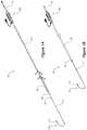
- the endograft introducer assembly 10 includes a pusher assembly 20, as is shown in Figure 1A .
- the pusher assembly 20 comprises a guide wire catheter 12, a tip 14 mounted to a proximal end 13 of the guide wire catheter 12 and a pusher 21.
- the pusher 21 has a handle 28.
- Figure 3 shows a stent graft receiving portion 24 and shows that the pusher 21 is distal of the stent graft receiving portion 24.
- a stent graft 200 is shown mounted on the receiving portion 24.
- Figure 4 also shows a transfer sheath 30.
- the transfer sheath 30 is in a position extending distally over the stent graft 200 from a proximal position 15 adjacent to the tip 14.
- a stopper 40 disposed coaxially around the transfer sheath 30 is shown.
- the stopper 40 has a proximal end 42 terminating in a stopper surface 44.
- This stopper surface 44 is more clearly shown in Figure 7A.
- Figure 7A also shows that the stopper 40 has a distal portion 46, the distal portion 46 being removably engaged with the transfer sheath 30, as is shown in Figures 4 and 5 for instance, so as to prevent relative movement between the stopper 40 and the transfer sheath 30 in at least one direction.
- the reaction force is transferred along the a stopper 40 to its distal portion 46 thereby preventing movement of the transfer sheath 30 towards the distal end face 120 (which functions as a reaction surface) as the pusher 21 is pushed in a direction towards the distal end face 120.
- the stopper 40 shown in Figure 7A and Figure 11A has a longitudinal split 45, the split 45 allowing the stopper 40 to flexibly open for lateral movement over the transfer sheath 30.
- Figure 11B shows the stopper forced open for removal from around the transfer sheath 30.
- alternative stoppers can be used.
- the stopper 40 illustrated in Figure 7B or the stopper 40 illustrated in Figure 7C can be used.
- the transfer sheath 30 has a first length TL, as is illustrated in Figure 5 . This length is sufficient to entirely cover the stent graft 200 illustrated in Figure 4 .
- the stopper 40 also illustrated in Figure 5 , has a second length SL. This second length, SL, is less than the first length. The reason for this becomes apparent when use of the introducer assembly 10 is explained (see below).
- the distal portion 46 of the stopper 40 has a receiving outer diameter A.
- This receiving outer diameter A receives a return portion 39 of the transfer sheath 30, as is shown in Figure 5 .
- the return portion 39 is arranged and constructed to prevent relative axial movement between the stopper 40 and the transfer sheath 30 in one direction.
- the receiving outer diameter A is smaller than the stopper surface 44 outer diameter B, as indicated on Figure 7A . This allows the stopper 40 to snuggly fit around the transfer sheath 30 at its distal end and to loosely fit around the transfer sheath 30 at, or towards, its distal end 37, where the stopper 40 has a constant wall thickness.
- the transfer sheath 30 is frangible so as to allow it to be removed from the pusher 21 without the need to be slid over an end of the pusher 21.
- the transfer sheath 30 comprises a bifurcated end 38 terminating in a pair of gripable tails 39a and 39b as can be seen in Figure 2 . These gripable tails 39a and 39b allow the operator to peel and remove the transfer sheath 30 from the pusher assembly 20.
- the transfer sheath 30 can thus be considered a "peelaway" component.
- Figures 1 and 5 show a peelaway plug 70.
- This peelaway plug 70 is provided to plug the distal end 37 of the transfer sheath 30. This ensures that the introducer assembly 10 can be flushed with a flushing fluid.
- the peelaway plug 70 may include gripable tails 79a and 79b, as illustrated in Figure 2 .
- Alternative plugs, such as the plug 70 schematically illustrated in Figure 5 may be used.
- the introducer assembly 10 is shown over a guide wire 8 adjacent a main sheath assembly 100.
- Figure 9 shows that the main sheath assembly 100 has a valve assembly 110 that has a distal end face 120 surrounding an aperture 125.
- a valve as is known in the art. The valve prevents, or at least minimises, blood leakage.
- Figure 10 shows the stopper 40 with its stopper surface 44 (shown in Figure 8 ) abutting the distal end face 120 of the valve assembly 110.
- the diameter B is larger than the diameter A, so as to ensure that the stopper surface 44 does not enter the aperture 125, and instead firmly abuts the annular distal end face 120, as is shown in Figure 10 .
- the stopper 40 has a first longitudinal stiffness and the transfer sheath 30 has a second longitudinal stiffness.
- the first longitudinal stiffness is greater than the second longitudinal stiffness.
- the longitudinal stiffness of the stopper 40 is such that when a person pushes the pusher 21 axially along the guide wire 8, as shown in Figure 8 , towards the main sheath assembly 100 so that the stopper surface 44 abuts the distal end face 120, a reaction force is transmitted from the stopper surface 44 along the stopper to the proximal end 38 of the transfer sheath 30. This reaction force is sufficient to prevent further movement of the transfer sheath 30 and thereby only allows the transfer sheath 30 to travel a small distance into the main sheath assembly 100.
- This distance is the difference between the lengths TL and SL, as illustrated in Figure 5 .
- the stent graft 200 begins to move axially with respect to the transfer sheath 30 such that it is transferred from the transfer sheath 30 into the main sheath 105. This prevents the transfer sheath 30 from progressing too far into the valve assembly 110 and hence prevents the transfer sheath 30 becoming jammed in the valve within the valve assembly 110.
- the relative length of the stopper 40 and the temporary transfer sheath 30 is such that the transfer sheath 30 is held at a pre-determined position inside the valve assembly 110, so as to prevent both the possibility of graft deployment within the valve assembly 110 and the possibility of the transfer sheath 30 becoming jammed inside the valve assembly 110.
- the longitudinal slit 45 is provided so that the stopper 40 is easily removable when no longer required.
- Figure 11A shows the stopper 40 of Figure 7A around the transfer sheath 30 and Figure 11B shows the stopper 40 of Figure 7A being removed from the transfer sheath 30.
- the material thickness and properties of the stopper 40 are such that, even with the longitudinal split 45, it is positively located so that it is not easily dislodged accidently from its coaxial position around the transfer sheath 30.
- An advantage of the arrangement described above is that its operators do not require as much training and do not need as much skill to transfer a graft 200 into a main sheath 100 during and endovascular procedure. Furthermore, the likelihood of jamming is reduces, as described above.
Landscapes
- Health & Medical Sciences (AREA)
- Engineering & Computer Science (AREA)
- Biomedical Technology (AREA)
- Cardiology (AREA)
- Oral & Maxillofacial Surgery (AREA)
- Transplantation (AREA)
- Heart & Thoracic Surgery (AREA)
- Vascular Medicine (AREA)
- Life Sciences & Earth Sciences (AREA)
- Animal Behavior & Ethology (AREA)
- General Health & Medical Sciences (AREA)
- Public Health (AREA)
- Veterinary Medicine (AREA)
- Media Introduction/Drainage Providing Device (AREA)
Abstract
Description
- The invention relates to medical devices and more particularly to a medical device used for deployment of an intraluminal graft or stent graft, otherwise referred to as an introducer or a stent graft introducer. In particular, this invention relates to an endograft introducer assembly having a transfer sheath.
- In the deployment of a graft, or stent graft, into the human or animal body via intraluminal techniques, a deployment device is used to introduce the stent graft into a lumen of the body and, after the stent graft has been deployed and expanded within the lumen, the introducer assembly is retracted.
- In some procedures, including some procedures using custom made devices, a main sheath assembly is required to be deployed into the vasculature independently of the graft. In such procedures, after the main sheath assembly is in place, a graft which is pre-compressed into a temporary tube or transfer tube is transferred into a main sheath of the main sheath assembly. At this time it is important that the transfer takes place safely and smoothly. When using currently known endograft introducer assemblies, this results in an additional workload for operating theatre staff and can add risk to the procedure.
- Throughout this specification, the term distal with respect to a portion of the aorta, a deployment device or an endograft means the end of the aorta, deployment device or endograft further away in the direction of blood flow away from the heart and the term proximal means the portion of the aorta, deployment device or end of the endograft nearer to the heart. When applied to other vessels, similar terms such as caudal and cranial should be understood.
- Aspects of the present invention are defined in the claims.
- According to a first aspect of the invention, there is provided an endograft introducer assembly comprising:
- a pusher assembly comprising a guide wire catheter, a tip mounted to a proximal end of the guide wire catheter, a stent graft receiving portion distal of the tip and a pusher distal of the receiving portion;
- a transfer sheath extending distally over the stent graft receiving portion from a proximal position adjacent to the tip, the transfer sheath having a first length over the stent graft receiving portion; and
- a stopper disposed co-axially around the transfer sheath, the stopper having a proximal end terminating in a stopper surface and a distal portion, the distal portion removably engaged with the transfer sheath so as to prevent relative axial movement between the stopper and the transfer sheath in at least one direction.
- Preferred embodiments of the invention address the problem of having to deploy a main sheath assembly into the vasculature independently of a graft, as described hereinbefore, or at least provide the practitioner in the field with a useful alternative device.
- In one form, the stopper has a second length, the second length less than the first length.
- In one form, the distal portion of the stopper comprises a transfer sheath receiving portion having a receiving outer diameter and wherein the stopper surface has a stopper outer diameter, the stopper outer diameter larger than the receiving outer diameter.
- In one form, the stopper has a longitudinal split, the split allowing the stopper to flexibly open for lateral movement over the transfer sheath.
- In one form, the transfer sheath comprises a return portion at a distal end thereof, the return portion arranged and constructed to prevent relative axial movement between the stopper and the transfer sheath in the at least one direction.
- In one form, the stopper has a first longitudinal stiffness and the transfer sheath has a second longitudinal stiffness, the first longitudinal stiffness greater than the second longitudinal stiffness.
- In one form, the transfer sheath is frangible so as to allow it to be removed from the pusher without the need to slide over an end of the pusher.
- In one form, the transfer sheath comprises a bifurcated end terminating in a pair of gripable tails.
- According to a second aspect of the invention, there is provided an assembly comprising:
- a pusher assembly comprising a guide wire catheter, a tip mounted to a proximal end of the guide wire catheter, a stent graft receiving portion distal of the tip and a pusher distal of the receiving portion;
- a transfer sheath extending distally over the stent graft receiving portion from a proximal position adjacent to the tip, the transfer sheath having a first length over the stent graft receiving portion and a stent graft mounted on the receiving portion; and
- a stopper disposed co-axially around the transfer sheath, the stopper having a proximal end terminating in a stopper surface and a distal portion, the distal portion removably engaged with the transfer sheath so as to prevent relative axial movement between the stopper and the transfer sheath in at least one direction.
- In one form, the stopper has a second length, the second length less than the first length.
- In one form, the distal portion of the stopper comprises a transfer sheath receiving portion having a receiving outer diameter and wherein the stopper surface has a stopper outer diameter, the stopper outer diameter larger than the receiving outer diameter.
- In one form, the stopper has a longitudinal split, the split allowing the stopper to flexibly open for lateral movement over the transfer sheath.
- In one form, the transfer sheath comprises a return portion at a distal end thereof, the return portion arranged and constructed to prevent relative axial movement between the stopper and the transfer sheath in the at least one direction.
- In one form, the stopper has a first longitudinal stiffness and the transfer sheath has a second longitudinal stiffness, the first longitudinal stiffness greater than the second longitudinal stiffness.
- In one form, the transfer sheath is frangible so as to allow it to be removed from the pusher without the need to slide over an end of the pusher.
- In one form, the transfer sheath comprises a bifurcated end terminating in a pair of gripable tails.
- According to a third aspect of the present invention a system comprises: a main sheath assembly having a valve assembly, the valve assembly having a distal end face surrounding an aperture; a pusher assembly comprising a guide wire catheter, a tip mounted to a proximal end of the guide wire catheter, a stent graft receiving portion distal of the tip and a pusher distal of the receiving portion; a transfer sheath extending distally over the stent graft receiving portion from a proximal position adjacent to the tip, the transfer sheath having a first length over the stent graft receiving portion and a stent graft mounted on the receiving portion; and a stopper disposed co-axially around the transfer sheath, the stopper having a proximal end terminating in a stopper surface and a distal portion, the distal portion removably engaged with the transfer sheath so as to prevent relative axial movement between the stopper and the transfer sheath in at least one direction, wherein, in use, when an operator pushes the pusher axially towards the main sheath assembly so that the stopper surface abuts the distal end face of the valve assembly, a reaction force is transmitted from the stopper surface along the stopper to the proximal end of the transfer sheath, such that the transfer sheath is held at a pre-determined position inside the valve assembly.
- The stopper may have a first longitudinal stiffness and the transfer sheath may have a second longitudinal stiffness, the first longitudinal stiffness may be greater than the second longitudinal stiffness. The distal portion of the stopper may comprise a transfer sheath receiving portion having a receiving outer diameter. The stopper surface may have a stopper outer diameter.The stopper outer diameter may be larger than the receiving outer diameter. The transfer sheath imay be frangible so as to allow it to be removed from the pusher without the need to slide over an end of the pusher. The transfer sheath may comprise a bifurcated end terminating in a pair of gripable tails.
- Embodiments of the present invention are described below, by way of example only, with reference to the accompanying drawings, wherein:
-
Figure 1A is an isometric view of an endograft introducer assembly according to the invention; -
Figure 1B is an isometric view of a pusher assembly which forms part of the endograft introducer assembly ofFigure 1A . -
Figure 2 is a close up view of a proximal end of the introducer assembly ofFigure 1A ; -
Figure 3 is a similar view to that ofFigure 2 , but shows a guide wire catheter and tip, also shown inFigures 1 and2 , in a straightened condition; -
Figure 4 is a similar view to that ofFigure 3 , but shows the introducer assembly ofFigures 1 to 3 loaded with a stent graft; -
Figures 5 and 6 are diagrammatic views showing a portion of the distal end of the introducer assembly shown inFigure 4 , but with the stent graft retracted and covered by a transfer sheath; -
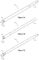
Figure 7A is a detailed isometric view of a stopper, the stopper being a component of the introducer assembly shown inFigures 1 to 6 ; -
Figures 7B and 7C show alternative embodiments of the stopper shown inFigure 7A ; -
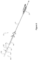
Figure 8 shows an isometric view of the introducer assembly ofFigures 1 to 6 on a guide wire being guided towards a main sheath assembly; -
Figure 9 is a close up view of a portion of the main sheath assembly shown inFigure 8 ; and -
Figure 10 is a similar view to that ofFigure 8 but is a close up view and shows the stopper of the introducer assembly abutting the main sheath assembly; -
Figure11A shows a diagrammatic end view of a stopper of the introducer assembly ofFigures 1 to 3 in an installed condition and being removed respectively. -
Figure 11B is a similar view to that ofFigure 11A , but shows the stopper being removed. - The components in the drawings are not necessarily to scale, emphasis instead being placed upon illustrating the principles of the teachings herein.
- Aspects of the present invention are defined in the appended claims.
- Referring to
Figure 1A , an endograft introducerassembly 10 according to the invention is shown. Theendograft introducer assembly 10 includes apusher assembly 20, as is shown inFigure 1A . Thepusher assembly 20 comprises aguide wire catheter 12, atip 14 mounted to aproximal end 13 of theguide wire catheter 12 and apusher 21. Thepusher 21 has ahandle 28. - Referring now to
Figures 2 and 3 , aproximal end 11 of theendograft introducer assembly 10 is shown more clearly.Figure 3 shows a stentgraft receiving portion 24 and shows that thepusher 21 is distal of the stentgraft receiving portion 24. - Referring now to
Figure 4 , astent graft 200 is shown mounted on the receivingportion 24.Figure 4 also shows atransfer sheath 30. - Turning now to
Figure 5 , thetransfer sheath 30 is in a position extending distally over thestent graft 200 from aproximal position 15 adjacent to thetip 14. - Again referring to
Figure 5 , astopper 40 disposed coaxially around thetransfer sheath 30 is shown. Thestopper 40 has aproximal end 42 terminating in astopper surface 44. Thisstopper surface 44 is more clearly shown inFigure 7A. Figure 7A also shows that thestopper 40 has adistal portion 46, thedistal portion 46 being removably engaged with thetransfer sheath 30, as is shown inFigures 4 and5 for instance, so as to prevent relative movement between thestopper 40 and thetransfer sheath 30 in at least one direction. More specifically, when thestopper surface 44 of thestopper 40 is pushed against a surface, such as thedistal end face 120 of thevalve assembly 110 shown inFigures 9 and 10 , the reaction force is transferred along the astopper 40 to itsdistal portion 46 thereby preventing movement of thetransfer sheath 30 towards the distal end face 120 (which functions as a reaction surface) as thepusher 21 is pushed in a direction towards thedistal end face 120. - The
stopper 40 shown inFigure 7A andFigure 11A has alongitudinal split 45, thesplit 45 allowing thestopper 40 to flexibly open for lateral movement over thetransfer sheath 30.Figure 11B shows the stopper forced open for removal from around thetransfer sheath 30. - In other embodiments of the invention, alternative stoppers can be used. For instance, the
stopper 40 illustrated inFigure 7B or thestopper 40 illustrated inFigure 7C can be used. - The
transfer sheath 30 has a first length TL, as is illustrated inFigure 5 . This length is sufficient to entirely cover thestent graft 200 illustrated inFigure 4 . Thestopper 40, also illustrated inFigure 5 , has a second length SL. This second length, SL, is less than the first length. The reason for this becomes apparent when use of theintroducer assembly 10 is explained (see below). - Referring again to
Figure 7A , it can be seen that thedistal portion 46 of thestopper 40 has a receiving outer diameter A. This receiving outer diameter A receives areturn portion 39 of thetransfer sheath 30, as is shown inFigure 5 . Thereturn portion 39 is arranged and constructed to prevent relative axial movement between thestopper 40 and thetransfer sheath 30 in one direction. - The receiving outer diameter A is smaller than the
stopper surface 44 outer diameter B, as indicated onFigure 7A . This allows thestopper 40 to snuggly fit around thetransfer sheath 30 at its distal end and to loosely fit around thetransfer sheath 30 at, or towards, itsdistal end 37, where thestopper 40 has a constant wall thickness. - The
transfer sheath 30 is frangible so as to allow it to be removed from thepusher 21 without the need to be slid over an end of thepusher 21. Thetransfer sheath 30 comprises abifurcated end 38 terminating in a pair ofgripable tails Figure 2 . Thesegripable tails transfer sheath 30 from thepusher assembly 20. Thetransfer sheath 30 can thus be considered a "peelaway" component. -
Figures 1 and5 show apeelaway plug 70. Thispeelaway plug 70 is provided to plug thedistal end 37 of thetransfer sheath 30. This ensures that theintroducer assembly 10 can be flushed with a flushing fluid. The peelaway plug 70 may includegripable tails Figure 2 . Alternative plugs, such as theplug 70 schematically illustrated inFigure 5 , may be used. - Referring to
Figure 8 , theintroducer assembly 10 is shown over aguide wire 8 adjacent amain sheath assembly 100.Figure 9 shows that themain sheath assembly 100 has avalve assembly 110 that has adistal end face 120 surrounding anaperture 125. Within theaperture 125 is a valve as is known in the art. The valve prevents, or at least minimises, blood leakage.Figure 10 shows thestopper 40 with its stopper surface 44 (shown inFigure 8 ) abutting thedistal end face 120 of thevalve assembly 110. As mentioned above, the diameter B is larger than the diameter A, so as to ensure that thestopper surface 44 does not enter theaperture 125, and instead firmly abuts the annulardistal end face 120, as is shown inFigure 10 . - The
stopper 40 has a first longitudinal stiffness and thetransfer sheath 30 has a second longitudinal stiffness. The first longitudinal stiffness is greater than the second longitudinal stiffness. The longitudinal stiffness of thestopper 40 is such that when a person pushes thepusher 21 axially along theguide wire 8, as shown inFigure 8 , towards themain sheath assembly 100 so that thestopper surface 44 abuts thedistal end face 120, a reaction force is transmitted from thestopper surface 44 along the stopper to theproximal end 38 of thetransfer sheath 30. This reaction force is sufficient to prevent further movement of thetransfer sheath 30 and thereby only allows thetransfer sheath 30 to travel a small distance into themain sheath assembly 100. This distance is the difference between the lengths TL and SL, as illustrated inFigure 5 . As thepusher 21 is further pushed into themain sheath assembly 100, thestent graft 200 begins to move axially with respect to thetransfer sheath 30 such that it is transferred from thetransfer sheath 30 into themain sheath 105. This prevents thetransfer sheath 30 from progressing too far into thevalve assembly 110 and hence prevents thetransfer sheath 30 becoming jammed in the valve within thevalve assembly 110. The relative length of thestopper 40 and thetemporary transfer sheath 30 is such that thetransfer sheath 30 is held at a pre-determined position inside thevalve assembly 110, so as to prevent both the possibility of graft deployment within thevalve assembly 110 and the possibility of thetransfer sheath 30 becoming jammed inside thevalve assembly 110. Thelongitudinal slit 45 is provided so that thestopper 40 is easily removable when no longer required.Figure 11A shows thestopper 40 ofFigure 7A around thetransfer sheath 30 andFigure 11B shows thestopper 40 ofFigure 7A being removed from the transfer sheath 30.The material thickness and properties of thestopper 40 are such that, even with thelongitudinal split 45, it is positively located so that it is not easily dislodged accidently from its coaxial position around thetransfer sheath 30. - An advantage of the arrangement described above is that its operators do not require as much training and do not need as much skill to transfer a
graft 200 into amain sheath 100 during and endovascular procedure. Furthermore, the likelihood of jamming is reduces, as described above. - Throughout the specification and the claims that follow, unless the context requires otherwise, the words "comprise" and "include" and variations such as "comprising" and "including" will be understood to imply the inclusion of a stated integer or group of integers, but not the exclusion of any other integer or group of integers.
- The reference to any prior art in this specification is not, and should not be taken as, an acknowledgement of any form of suggestion that such prior art forms part of the common general knowledge.
- It will be appreciated by those skilled in the art that the invention is not restricted in its use to the particular application described. Neither is the present invention restricted in its preferred embodiment with regard to the particular elements and/or features described or depicted herein. It will be appreciated that the invention is not limited to the embodiment or embodiments disclosed, but is capable of numerous rearrangements, modifications and substitutions without departing from the scope of the invention as set forth and defined by the following claims.
- All optional and preferred features and modifications of the described embodiments and dependent claims are usable in all aspects of the invention taught herein. Furthermore, the individual features of the dependent claims, as well as all optional and preferred features and modifications of the described embodiments are combinable and interchangeable with one another.
- The disclosures in Australian patent application number
2015201411
Claims (13)
- An endograft introducer assembly comprising:a pusher assembly comprising a guide wire catheter, a tip mounted to a proximal end of the guide wire catheter, a stent graft receiving portion distal of the tip and a pusher distal of the receiving portion;a transfer sheath extending distally over the stent graft receiving portion from a proximal position adjacent to the tip, the transfer sheath having a first length over the stent graft receiving portion; anda stopper disposed co-axially around the transfer sheath, the stopper having a proximal end terminating in a stopper surface and a distal portion, the distal portion removably engaged with the transfer sheath so as to prevent relative axial movement between the stopper and the transfer sheath in at least one direction,wherein the distal portion of the stopper comprises a transfer sheath receiving portion having a receiving outer diameter and wherein the stopper surface has a stopper outer diameter, the stopper outer diameter larger than the receiving outer diameter.
- An introducer assembly according to claim 1 comprising a stent graft mounted on the receiving portion.
- The introducer assembly of any preceding claim wherein the stopper has a second length, the second length less than the first length.
- The introducer assembly of any preceding claim wherein the stopper has a longitudinal split, the split allowing the stopper to flexibly open for lateral movement over the transfer sheath.
- The introducer assembly of any preceding claim wherein the transfer sheath comprises a return portion at a distal end thereof, the return portion arranged and constructed to prevent relative axial movement between the stopper and the transfer sheath in the at least one direction.
- The introducer assembly of any preceding claim wherein the stopper has a first longitudinal stiffness and the transfer sheath has a second longitudinal stiffness, the first longitudinal stiffness greater than the second longitudinal stiffness.
- The introducer assembly of any preceding claim wherein the transfer sheath is frangible so as to allow it to be removed from the pusher without the need to slide over an end of the pusher.
- The introducer assembly of any preceding claim wherein the transfer sheath comprises a bifurcated end terminating in a pair of gripable tails.
- A system comprising:a main sheath assembly having a valve assembly, the valve assembly having a distal end face surrounding an aperture;a pusher assembly comprising a guide wire catheter, a tip mounted to a proximal end of the guide wire catheter, a stent graft receiving portion distal of the tip and a pusher distal of the receiving portion;a transfer sheath extending distally over the stent graft receiving portion from a proximal position adjacent to the tip, the transfer sheath having a first length over the stent graft receiving portion and a stent graft mounted on the receiving portion; anda stopper disposed co-axially around the transfer sheath, the stopper having a proximal end terminating in a stopper surface and a distal portion, the distal portion removably engaged with the transfer sheath so as to prevent relative axial movement between the stopper and the transfer sheath in at least one direction,wherein, in use, when an operator pushes the pusher axially towards the main sheath assembly so that the stopper surface abuts the distal end face of the valve assembly, a reaction force is transmitted from the stopper surface along the stopper to the proximal end of the transfer sheath, such that the transfer sheath is held at a pre-determined position inside the valve assembly.
- The assembly of claim 9 wherein the stopper has a first longitudinal stiffness and the transfer sheath has a second longitudinal stiffness, the first longitudinal stiffness greater than the second longitudinal stiffness.
- The assembly of any of claims 9 and 10 wherein the distal portion of the stopper comprises a transfer sheath receiving portion having a receiving outer diameter and wherein the stopper surface has a stopper outer diameter, the stopper outer diameter larger than the receiving outer diameter.
- The assembly of any of claims 9 to 11 wherein the transfer sheath is frangible so as to allow it to be removed from the pusher without the need to slide over an end of the pusher.
- The assembly of any of claims 9 to 12 wherein the transfer sheath comprises a bifurcated end terminating in a pair of gripable tails.
Applications Claiming Priority (1)
| Application Number | Priority Date | Filing Date | Title |
|---|---|---|---|
| AU2015201411A AU2015201411B1 (en) | 2015-03-18 | 2015-03-18 | An endograft introducer assembly having a transfer sheath |
Publications (2)
| Publication Number | Publication Date |
|---|---|
| EP3069695A1 true EP3069695A1 (en) | 2016-09-21 |
| EP3069695B1 EP3069695B1 (en) | 2017-12-20 |
Family
ID=54198718
Family Applications (1)
| Application Number | Title | Priority Date | Filing Date |
|---|---|---|---|
| EP16275001.2A Active EP3069695B1 (en) | 2015-03-18 | 2016-01-04 | An endograft introducer assembly having a transfer sheath |
Country Status (3)
| Country | Link |
|---|---|
| US (1) | US10583023B2 (en) |
| EP (1) | EP3069695B1 (en) |
| AU (1) | AU2015201411B1 (en) |
Citations (2)
| Publication number | Priority date | Publication date | Assignee | Title |
|---|---|---|---|---|
| EP2749258A1 (en) * | 2012-12-28 | 2014-07-02 | Cook Medical Technologies LLC | Endoluminal prosthesis introducer |
| WO2014204758A1 (en) * | 2013-06-21 | 2014-12-24 | Abbott Cardiovascular Systems Inc. | Removable sheath assembly for a polymer scaffold |
Family Cites Families (11)
| Publication number | Priority date | Publication date | Assignee | Title |
|---|---|---|---|---|
| US6254628B1 (en) * | 1996-12-09 | 2001-07-03 | Micro Therapeutics, Inc. | Intracranial stent |
| US6228073B1 (en) * | 1998-12-15 | 2001-05-08 | Medtronic, Inc. | Angiography luer hub having wings proximal to the plurality of grips and strain relief |
| AU768071B2 (en) | 1999-01-22 | 2003-12-04 | W.L. Gore & Associates, Inc. | Low profile stent and graft combination |
| US7163552B2 (en) | 2000-10-13 | 2007-01-16 | Medtronic Vascular, Inc. | Stent delivery system with hydraulic deployment |
| US20080264102A1 (en) | 2004-02-23 | 2008-10-30 | Bolton Medical, Inc. | Sheath Capture Device for Stent Graft Delivery System and Method for Operating Same |
| EP1819391B1 (en) | 2004-09-09 | 2020-02-19 | Onset Medical Corporation | Expandable transluminal sheath |
| GB0512321D0 (en) * | 2005-06-16 | 2005-07-27 | Angiomed Ag | Catheter device double swaging |
| US8216302B2 (en) | 2005-10-26 | 2012-07-10 | Cardiosolutions, Inc. | Implant delivery and deployment system and method |
| US8382794B2 (en) * | 2006-01-04 | 2013-02-26 | St. Jude Medical Puerto Rico Llc | Balloon insertion apparatus and method of sealing a tissue puncture |
| US9101507B2 (en) * | 2011-05-18 | 2015-08-11 | Ralph F. Caselnova | Apparatus and method for proximal-to-distal endoluminal stent deployment |
| US20120296313A1 (en) * | 2011-05-20 | 2012-11-22 | Abbott Cardiovascular Systems Inc. | Drug Coated Balloon Hemostatic Valve Insertion/Balloon Sheath |
-
2015
- 2015-03-18 AU AU2015201411A patent/AU2015201411B1/en active Active
-
2016
- 2016-01-04 EP EP16275001.2A patent/EP3069695B1/en active Active
- 2016-03-18 US US15/074,084 patent/US10583023B2/en active Active
Patent Citations (2)
| Publication number | Priority date | Publication date | Assignee | Title |
|---|---|---|---|---|
| EP2749258A1 (en) * | 2012-12-28 | 2014-07-02 | Cook Medical Technologies LLC | Endoluminal prosthesis introducer |
| WO2014204758A1 (en) * | 2013-06-21 | 2014-12-24 | Abbott Cardiovascular Systems Inc. | Removable sheath assembly for a polymer scaffold |
Also Published As
| Publication number | Publication date |
|---|---|
| EP3069695B1 (en) | 2017-12-20 |
| US10583023B2 (en) | 2020-03-10 |
| US20160270937A1 (en) | 2016-09-22 |
| AU2015201411B1 (en) | 2015-09-24 |
Similar Documents
| Publication | Publication Date | Title |
|---|---|---|
| JP5347175B2 (en) | Introducer | |
| EP1863402B1 (en) | Exchangeable delivery system with distal protection | |
| EP3773361B1 (en) | Prosthesis delivery system with tip travel limiter | |
| EP2043566B1 (en) | Medical device introducer with docking arrangement | |
| US9186482B2 (en) | Elongate medical device | |
| EP2604232B1 (en) | Circumferential trigger wire for deploying an endoluminal prosthesis | |
| EP2661244B1 (en) | Proximal release expandable prosthesis delivery system | |
| US20070250151A1 (en) | Endovascular aortic repair delivery system with anchor | |
| EP2366364A1 (en) | Deploying medical implants | |
| US20100274340A1 (en) | Deployment device | |
| US9101507B2 (en) | Apparatus and method for proximal-to-distal endoluminal stent deployment | |
| EP2921144B1 (en) | A capsule assembly for a medical device introducer | |
| EP2870947B1 (en) | An endograft introducer and a capsule assembly for an endograft introducer | |
| EP3069695B1 (en) | An endograft introducer assembly having a transfer sheath | |
| EP3037072B1 (en) | Introducer with side opening | |
| EP3251634B1 (en) | Medical device introducer assembly particularly for branched medical devices | |
| EP3040057B1 (en) | Prosthesis delivery systems having an atraumatic tip for use with trigger wires | |
| EP3407833B1 (en) | Trans-aortic proximal aortic stent graft | |
| JP2019536524A (en) | Driver and set for insertion of connectable implants |
Legal Events
| Date | Code | Title | Description |
|---|---|---|---|
| PUAI | Public reference made under article 153(3) epc to a published international application that has entered the european phase |
Free format text: ORIGINAL CODE: 0009012 |
|
| AK | Designated contracting states |
Kind code of ref document: A1 Designated state(s): AL AT BE BG CH CY CZ DE DK EE ES FI FR GB GR HR HU IE IS IT LI LT LU LV MC MK MT NL NO PL PT RO RS SE SI SK SM TR |
|
| AX | Request for extension of the european patent |
Extension state: BA ME |
|
| 17P | Request for examination filed |
Effective date: 20160914 |
|
| RBV | Designated contracting states (corrected) |
Designated state(s): AL AT BE BG CH CY CZ DE DK EE ES FI FR GB GR HR HU IE IS IT LI LT LU LV MC MK MT NL NO PL PT RO RS SE SI SK SM TR |
|
| GRAP | Despatch of communication of intention to grant a patent |
Free format text: ORIGINAL CODE: EPIDOSNIGR1 |
|
| STAA | Information on the status of an ep patent application or granted ep patent |
Free format text: STATUS: GRANT OF PATENT IS INTENDED |
|
| INTG | Intention to grant announced |
Effective date: 20170906 |
|
| GRAS | Grant fee paid |
Free format text: ORIGINAL CODE: EPIDOSNIGR3 |
|
| GRAA | (expected) grant |
Free format text: ORIGINAL CODE: 0009210 |
|
| STAA | Information on the status of an ep patent application or granted ep patent |
Free format text: STATUS: THE PATENT HAS BEEN GRANTED |
|
| AK | Designated contracting states |
Kind code of ref document: B1 Designated state(s): AL AT BE BG CH CY CZ DE DK EE ES FI FR GB GR HR HU IE IS IT LI LT LU LV MC MK MT NL NO PL PT RO RS SE SI SK SM TR |
|
| REG | Reference to a national code |
Ref country code: GB Ref legal event code: FG4D |
|
| REG | Reference to a national code |
Ref country code: CH Ref legal event code: EP |
|
| REG | Reference to a national code |
Ref country code: IE Ref legal event code: FG4D |
|
| REG | Reference to a national code |
Ref country code: AT Ref legal event code: REF Ref document number: 955681 Country of ref document: AT Kind code of ref document: T Effective date: 20180115 |
|
| REG | Reference to a national code |
Ref country code: DE Ref legal event code: R096 Ref document number: 602016001147 Country of ref document: DE |
|
| REG | Reference to a national code |
Ref country code: NL Ref legal event code: MP Effective date: 20171220 |
|
| PG25 | Lapsed in a contracting state [announced via postgrant information from national office to epo] |
Ref country code: NO Free format text: LAPSE BECAUSE OF FAILURE TO SUBMIT A TRANSLATION OF THE DESCRIPTION OR TO PAY THE FEE WITHIN THE PRESCRIBED TIME-LIMIT Effective date: 20180320 Ref country code: SE Free format text: LAPSE BECAUSE OF FAILURE TO SUBMIT A TRANSLATION OF THE DESCRIPTION OR TO PAY THE FEE WITHIN THE PRESCRIBED TIME-LIMIT Effective date: 20171220 Ref country code: LT Free format text: LAPSE BECAUSE OF FAILURE TO SUBMIT A TRANSLATION OF THE DESCRIPTION OR TO PAY THE FEE WITHIN THE PRESCRIBED TIME-LIMIT Effective date: 20171220 Ref country code: FI Free format text: LAPSE BECAUSE OF FAILURE TO SUBMIT A TRANSLATION OF THE DESCRIPTION OR TO PAY THE FEE WITHIN THE PRESCRIBED TIME-LIMIT Effective date: 20171220 |
|
| REG | Reference to a national code |
Ref country code: LT Ref legal event code: MG4D |
|
| REG | Reference to a national code |
Ref country code: AT Ref legal event code: MK05 Ref document number: 955681 Country of ref document: AT Kind code of ref document: T Effective date: 20171220 |
|
| PG25 | Lapsed in a contracting state [announced via postgrant information from national office to epo] |
Ref country code: RS Free format text: LAPSE BECAUSE OF FAILURE TO SUBMIT A TRANSLATION OF THE DESCRIPTION OR TO PAY THE FEE WITHIN THE PRESCRIBED TIME-LIMIT Effective date: 20171220 Ref country code: HR Free format text: LAPSE BECAUSE OF FAILURE TO SUBMIT A TRANSLATION OF THE DESCRIPTION OR TO PAY THE FEE WITHIN THE PRESCRIBED TIME-LIMIT Effective date: 20171220 Ref country code: LV Free format text: LAPSE BECAUSE OF FAILURE TO SUBMIT A TRANSLATION OF THE DESCRIPTION OR TO PAY THE FEE WITHIN THE PRESCRIBED TIME-LIMIT Effective date: 20171220 Ref country code: GR Free format text: LAPSE BECAUSE OF FAILURE TO SUBMIT A TRANSLATION OF THE DESCRIPTION OR TO PAY THE FEE WITHIN THE PRESCRIBED TIME-LIMIT Effective date: 20180321 Ref country code: BG Free format text: LAPSE BECAUSE OF FAILURE TO SUBMIT A TRANSLATION OF THE DESCRIPTION OR TO PAY THE FEE WITHIN THE PRESCRIBED TIME-LIMIT Effective date: 20180320 |
|
| PG25 | Lapsed in a contracting state [announced via postgrant information from national office to epo] |
Ref country code: NL Free format text: LAPSE BECAUSE OF FAILURE TO SUBMIT A TRANSLATION OF THE DESCRIPTION OR TO PAY THE FEE WITHIN THE PRESCRIBED TIME-LIMIT Effective date: 20171220 |
|
| PG25 | Lapsed in a contracting state [announced via postgrant information from national office to epo] |
Ref country code: ES Free format text: LAPSE BECAUSE OF FAILURE TO SUBMIT A TRANSLATION OF THE DESCRIPTION OR TO PAY THE FEE WITHIN THE PRESCRIBED TIME-LIMIT Effective date: 20171220 Ref country code: SK Free format text: LAPSE BECAUSE OF FAILURE TO SUBMIT A TRANSLATION OF THE DESCRIPTION OR TO PAY THE FEE WITHIN THE PRESCRIBED TIME-LIMIT Effective date: 20171220 Ref country code: CZ Free format text: LAPSE BECAUSE OF FAILURE TO SUBMIT A TRANSLATION OF THE DESCRIPTION OR TO PAY THE FEE WITHIN THE PRESCRIBED TIME-LIMIT Effective date: 20171220 Ref country code: EE Free format text: LAPSE BECAUSE OF FAILURE TO SUBMIT A TRANSLATION OF THE DESCRIPTION OR TO PAY THE FEE WITHIN THE PRESCRIBED TIME-LIMIT Effective date: 20171220 Ref country code: CY Free format text: LAPSE BECAUSE OF FAILURE TO SUBMIT A TRANSLATION OF THE DESCRIPTION OR TO PAY THE FEE WITHIN THE PRESCRIBED TIME-LIMIT Effective date: 20171220 |
|
| PG25 | Lapsed in a contracting state [announced via postgrant information from national office to epo] |
Ref country code: SM Free format text: LAPSE BECAUSE OF FAILURE TO SUBMIT A TRANSLATION OF THE DESCRIPTION OR TO PAY THE FEE WITHIN THE PRESCRIBED TIME-LIMIT Effective date: 20171220 Ref country code: PL Free format text: LAPSE BECAUSE OF FAILURE TO SUBMIT A TRANSLATION OF THE DESCRIPTION OR TO PAY THE FEE WITHIN THE PRESCRIBED TIME-LIMIT Effective date: 20171220 Ref country code: IT Free format text: LAPSE BECAUSE OF FAILURE TO SUBMIT A TRANSLATION OF THE DESCRIPTION OR TO PAY THE FEE WITHIN THE PRESCRIBED TIME-LIMIT Effective date: 20171220 Ref country code: RO Free format text: LAPSE BECAUSE OF FAILURE TO SUBMIT A TRANSLATION OF THE DESCRIPTION OR TO PAY THE FEE WITHIN THE PRESCRIBED TIME-LIMIT Effective date: 20171220 Ref country code: IS Free format text: LAPSE BECAUSE OF FAILURE TO SUBMIT A TRANSLATION OF THE DESCRIPTION OR TO PAY THE FEE WITHIN THE PRESCRIBED TIME-LIMIT Effective date: 20180420 Ref country code: AT Free format text: LAPSE BECAUSE OF FAILURE TO SUBMIT A TRANSLATION OF THE DESCRIPTION OR TO PAY THE FEE WITHIN THE PRESCRIBED TIME-LIMIT Effective date: 20171220 |
|
| REG | Reference to a national code |
Ref country code: DE Ref legal event code: R097 Ref document number: 602016001147 Country of ref document: DE |
|
| PG25 | Lapsed in a contracting state [announced via postgrant information from national office to epo] |
Ref country code: MC Free format text: LAPSE BECAUSE OF FAILURE TO SUBMIT A TRANSLATION OF THE DESCRIPTION OR TO PAY THE FEE WITHIN THE PRESCRIBED TIME-LIMIT Effective date: 20171220 |
|
| PG25 | Lapsed in a contracting state [announced via postgrant information from national office to epo] |
Ref country code: FR Free format text: LAPSE BECAUSE OF NON-PAYMENT OF DUE FEES Effective date: 20180220 Ref country code: LU Free format text: LAPSE BECAUSE OF NON-PAYMENT OF DUE FEES Effective date: 20180104 |
|
| PLBE | No opposition filed within time limit |
Free format text: ORIGINAL CODE: 0009261 |
|
| REG | Reference to a national code |
Ref country code: FR Ref legal event code: ST Effective date: 20180928 |
|
| STAA | Information on the status of an ep patent application or granted ep patent |
Free format text: STATUS: NO OPPOSITION FILED WITHIN TIME LIMIT |
|
| REG | Reference to a national code |
Ref country code: BE Ref legal event code: MM Effective date: 20180131 |
|
| PG25 | Lapsed in a contracting state [announced via postgrant information from national office to epo] |
Ref country code: DK Free format text: LAPSE BECAUSE OF FAILURE TO SUBMIT A TRANSLATION OF THE DESCRIPTION OR TO PAY THE FEE WITHIN THE PRESCRIBED TIME-LIMIT Effective date: 20171220 Ref country code: BE Free format text: LAPSE BECAUSE OF NON-PAYMENT OF DUE FEES Effective date: 20180131 |
|
| 26N | No opposition filed |
Effective date: 20180921 |
|
| PG25 | Lapsed in a contracting state [announced via postgrant information from national office to epo] |
Ref country code: SI Free format text: LAPSE BECAUSE OF FAILURE TO SUBMIT A TRANSLATION OF THE DESCRIPTION OR TO PAY THE FEE WITHIN THE PRESCRIBED TIME-LIMIT Effective date: 20171220 |
|
| REG | Reference to a national code |
Ref country code: CH Ref legal event code: PL |
|
| PG25 | Lapsed in a contracting state [announced via postgrant information from national office to epo] |
Ref country code: CH Free format text: LAPSE BECAUSE OF NON-PAYMENT OF DUE FEES Effective date: 20190131 Ref country code: LI Free format text: LAPSE BECAUSE OF NON-PAYMENT OF DUE FEES Effective date: 20190131 |
|
| PG25 | Lapsed in a contracting state [announced via postgrant information from national office to epo] |
Ref country code: MT Free format text: LAPSE BECAUSE OF NON-PAYMENT OF DUE FEES Effective date: 20180104 |
|
| PG25 | Lapsed in a contracting state [announced via postgrant information from national office to epo] |
Ref country code: TR Free format text: LAPSE BECAUSE OF FAILURE TO SUBMIT A TRANSLATION OF THE DESCRIPTION OR TO PAY THE FEE WITHIN THE PRESCRIBED TIME-LIMIT Effective date: 20171220 |
|
| PG25 | Lapsed in a contracting state [announced via postgrant information from national office to epo] |
Ref country code: PT Free format text: LAPSE BECAUSE OF FAILURE TO SUBMIT A TRANSLATION OF THE DESCRIPTION OR TO PAY THE FEE WITHIN THE PRESCRIBED TIME-LIMIT Effective date: 20171220 |
|
| PG25 | Lapsed in a contracting state [announced via postgrant information from national office to epo] |
Ref country code: MK Free format text: LAPSE BECAUSE OF NON-PAYMENT OF DUE FEES Effective date: 20171220 Ref country code: HU Free format text: LAPSE BECAUSE OF FAILURE TO SUBMIT A TRANSLATION OF THE DESCRIPTION OR TO PAY THE FEE WITHIN THE PRESCRIBED TIME-LIMIT; INVALID AB INITIO Effective date: 20160104 |
|
| PG25 | Lapsed in a contracting state [announced via postgrant information from national office to epo] |
Ref country code: AL Free format text: LAPSE BECAUSE OF FAILURE TO SUBMIT A TRANSLATION OF THE DESCRIPTION OR TO PAY THE FEE WITHIN THE PRESCRIBED TIME-LIMIT Effective date: 20171220 |
|
| P01 | Opt-out of the competence of the unified patent court (upc) registered |
Effective date: 20230602 |
|
| PGFP | Annual fee paid to national office [announced via postgrant information from national office to epo] |
Ref country code: GB Payment date: 20260126 Year of fee payment: 11 |
|
| PGFP | Annual fee paid to national office [announced via postgrant information from national office to epo] |
Ref country code: DE Payment date: 20260127 Year of fee payment: 11 Ref country code: IE Payment date: 20260120 Year of fee payment: 11 |