EP3069426B1 - Verfahren und vorrichtung für einen reaktorwindungsschutz - Google Patents
Verfahren und vorrichtung für einen reaktorwindungsschutz Download PDFInfo
- Publication number
- EP3069426B1 EP3069426B1 EP13897331.8A EP13897331A EP3069426B1 EP 3069426 B1 EP3069426 B1 EP 3069426B1 EP 13897331 A EP13897331 A EP 13897331A EP 3069426 B1 EP3069426 B1 EP 3069426B1
- Authority
- EP
- European Patent Office
- Prior art keywords
- voltage
- zero sequence
- sequence
- negative sequence
- turn
- Prior art date
- Legal status (The legal status is an assumption and is not a legal conclusion. Google has not performed a legal analysis and makes no representation as to the accuracy of the status listed.)
- Active
Links
Images


Classifications
-
- H—ELECTRICITY
- H02—GENERATION; CONVERSION OR DISTRIBUTION OF ELECTRIC POWER
- H02H—EMERGENCY PROTECTIVE CIRCUIT ARRANGEMENTS
- H02H7/00—Emergency protective circuit arrangements specially adapted for specific types of electric machines or apparatus or for sectionalised protection of cable or line systems, and effecting automatic switching in the event of an undesired change from normal working conditions
- H02H7/008—Emergency protective circuit arrangements specially adapted for specific types of electric machines or apparatus or for sectionalised protection of cable or line systems, and effecting automatic switching in the event of an undesired change from normal working conditions for protective arrangements according to this subclass
-
- G—PHYSICS
- G01—MEASURING; TESTING
- G01R—MEASURING ELECTRIC VARIABLES; MEASURING MAGNETIC VARIABLES
- G01R31/00—Arrangements for testing electric properties; Arrangements for locating electric faults; Arrangements for electrical testing characterised by what is being tested not provided for elsewhere
- G01R31/50—Testing of electric apparatus, lines, cables or components for short-circuits, continuity, leakage current or incorrect line connections
- G01R31/72—Testing of electric windings
-
- G—PHYSICS
- G01—MEASURING; TESTING
- G01R—MEASURING ELECTRIC VARIABLES; MEASURING MAGNETIC VARIABLES
- G01R31/00—Arrangements for testing electric properties; Arrangements for locating electric faults; Arrangements for electrical testing characterised by what is being tested not provided for elsewhere
- G01R31/50—Testing of electric apparatus, lines, cables or components for short-circuits, continuity, leakage current or incorrect line connections
- G01R31/52—Testing for short-circuits, leakage current or ground faults
-
- G—PHYSICS
- G01—MEASURING; TESTING
- G01R—MEASURING ELECTRIC VARIABLES; MEASURING MAGNETIC VARIABLES
- G01R31/00—Arrangements for testing electric properties; Arrangements for locating electric faults; Arrangements for electrical testing characterised by what is being tested not provided for elsewhere
- G01R31/50—Testing of electric apparatus, lines, cables or components for short-circuits, continuity, leakage current or incorrect line connections
- G01R31/62—Testing of transformers
Definitions
- the present invention relates to electrical technologies. More particularly, the present invention relates to a method and apparatus of reactor turn-to-turn protection.
- HV shunt reactors are also widely used to limit the arc current and improve the success rate of single phase auto-reclosing.
- HV shunt reactors consisted by high capacity inductance coils connected to HV transmission lines, which are indispensable elements in the current HV power grids. They play a vital role for stability and security of the whole power system. Same with other electrical equipment, as a consequence, the appropriate protection apparatus is necessary for the operation of HV shunt reactors.
- Chinese patent CN. 101651328B discloses a method of reactor turn-to-turn protection. This method can improve the sensitivity of inter-turn protection, but it may cause false operation in some transient process. At the same time, overcompensation and under compensation always exist due to the changes of the system operation mode, and the value of zero-sequence compensating voltage is difficult to be determined.
- Chinese patent CN. 101505051A provides a method for protecting interturn short circuits of a stator of a power generator based on negative sequence voltage distribution.
- the method not only reflects various asymmetric failures in the generator, but also can reflect partial internal failures of a main transformer and a transformer for a generator terminal plant; compared with a vertical zero sequence voltage proposal, the method can be easily dualized without increasing primary equipment; when a interphase fault close to the neutral point of the generator is generated, the protection can achieve higher sensibility; and the method can also protect the generator which is not merged into system operation.
- Chinese patent CN. 1555116A discloses a method for differentiating unbalance three phases and interturn short circuits by fault-tolerant re-judging to each electricity quantity of the reactor beginning and end when a high voltage parallel reactor operates normally including the following steps: a reactor protection device samples the current, voltage waveforms of mutual-inductor to get the transient value, the plural form of each electricity is evaluated by Fourier algorithm. When the measured zero-sequence voltage is bigger, a phase-comparison relay is used directly, if it's in positive direction, then the master criterion operates. When the zero-sequence voltage is small, the adaptive zero-sequence voltage compensation is carried out to compare the phase, if it's in the positive direction, then the master criterion operates.
- the present invention provides in an aspect a method of reactor turn-to-turn protection, the method comprising:
- the method comprising: acquiring an open triangle zero sequence voltage of the high voltage as the actual zero sequence voltage U ⁇ 0 acquiring a CT zero sequence current of the neutral point of the reactor as the actual zero sequence current I ⁇ 0 f .
- U o p .0
- U r e s .0
- U op. 0 represents the zero sequence operation quantity,
- U res. 0 represents the zero sequence restraining quantity,
- U ⁇ 0 represents the actual zero sequence voltage,
- U ⁇ 0 ′ represents the virtual zero sequence voltage.
- U o p .2
- U r e s .2
- U op. 2 represents the negative sequence operation quantity,
- U res. 2 represents the negative sequence restraining quantity,
- U ⁇ 2 represents the actual negative sequence voltage,
- U ⁇ 2 ′ represents the virtual negative sequence voltage.
- the present invention provides in an aspect an apparatus of reactor turn-to-turn protection, comprising:
- the apparatus further comprising: an acquiring unit, adapted to acquire a phase voltage of high voltage end of the reactor and a phase current of low voltage end of the reactor , to determine the actual zero sequence voltage U ⁇ 0 based on the phase voltage of high voltage end, and to determine the actual zero sequence current I ⁇ 0 f based on the phase current of low voltage end.
- the apparatus further comprising: an acquiring unit, adapted to acquire a phase voltage of high voltage end of the reactor and a phase current of low voltage end of the reactor and to determine the actual negative sequence voltage U ⁇ 2 based on the phase voltage of high voltage end, and to determine the actual negative sequence current I ⁇ 2 f based on the phase current of low voltage end.
- the apparatus further comprising: an acquiring unit, adapted to acquire an open triangle zero sequence voltage of the high voltage as the actual zero sequence voltage U ⁇ 0 , and to acquire a CT zero sequence current of the neutral point of the reactor as the actual zero sequence current I ⁇ 0 f .
- the performing unit adapted to:
- the performing unit adapted to:
- U o p .0
- U r e s .0
- U op .0 represents the zero sequence operation quantity,
- U res .0 represents the zero sequence restraining quantity,
- U ⁇ 0 represents the actual zero sequence voltage,
- U ⁇ 0 ′ represents the virtual zero sequence voltage.
- U o p .2
- U r e s .2
- U op. 2 represents the negative sequence operation quantity,
- U res .2 represents the negative sequence restraining quantity,
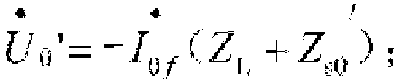
- U • 2 represents the actual negative sequence voltage,
- I • 0 f represents the actual zero sequence current
- Z L represents phase reactance of the reactor
- Z s0 ' represents neutral point reactance.
- the virtual voltage determining unit adapted to calculate the virtual negative sequence voltage U • 2 ' ;
- U • 2 ' ⁇ I 2 f • Z L ;
- I • 2 f represents the actual negative sequence current,
- Z L represents phase reactance of the reactor.
- the present invention is simple, intuitive, less affected by the variance of system operating mode and has higher sensitivity and reliability.
- the present invention disclosures a new reactor inter-turn (turn-to-turn) short circuit detection solution.
- Figure 1 represents a flow chart depicting a method of reactor turn-to-turn protection according to the present invention.
- the method comprises following steps: Step 101: determining a virtual zero sequence voltage based on an actually measured zero sequence current (or say, actual zero sequence current); and/or determining a virtual negative sequence voltage based on an actually measured negative-sequence current (or say, actual negative sequence current).
- a phase voltage of high voltage end of the reactor and a phase current of low voltage end of the reactor are acquired; and the actual zero sequence voltage is determined based on the phase voltage of high voltage end, the actual zero sequence current is determined based on the phase current of low voltage end.
- a phase voltage of high voltage end of the reactor and a phase current of low voltage end of the reactor are acquired; and the actual negative sequence voltage is determined based on the phase voltage of high voltage end, the actual negative sequence current is determined based on the phase current of low voltage end.
- an open triangle zero sequence voltage of the high voltage is obtained as the actual zero sequence voltage
- a CT zero sequence current of the neutral point of the reactor is obtained as the actual zero sequence current
- Step 102 determining a zero sequence operation quantity and a zero sequence restraining quantity based on an actual zero sequence voltage and the virtual zero sequence voltage; and/or determining a negative sequence operation quantity and a negative sequence restraining quantity based on an actual negative sequence voltage and the virtual z negative sequence voltage.
- U o p .0
- U r e s .0
- U op .0 represents the zero sequence operation quantity,
- U res. 0 represents the zero sequence restraining quantity,
- U ⁇ 0 represents the actual zero sequence voltage,
- U • 0 ' represents the virtual zero sequence voltage.
- U o p .2
- U r e s .2
- U op. 2 represents the negative sequence operation quantity
- U res. 2 represents the negative sequence restraining quantity
- U • 2 represents the actual negative sequence voltage
- U 2 ' • represents the virtual negative sequence voltage.
- Step103 performing a turn-to-turn protection when the zero sequence operation quantity is greater than the zero sequence restraining quantity, and/or when the negative sequence operation quantity is greater than the negative sequence restraining quantity.
- the step of performing a turn-to-turn protection may include the step of sending trip instructions to a breaker connected to the high voltage end of the reactor.
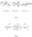
- Figure 2 shows zero sequence networks respectively when turn-to-turn short circuit or external earth fault occurred according to the present invention.
- E • F 1 , E • F 2 are the equivalent power sources in the zero sequence networks respectively when turn-to-turn short circuit or external earth fault occurred.
- U ⁇ op and U ⁇ res are diagonal lines of the parallelogram whose side length is U ⁇ 0 and U • 0 ' .
- the combined criterion can be described as follows:
- the Zero sequence criterion: Set U o p .0
- and U r e s .0
- the Negative sequence criterion: Set U o p .2
- and U r e s .2
- U • 2 is the negative sequence voltage measured in the location where the protection is installed.
- U ⁇ ' 2 is the virtual negative sequence voltage similar to U • 0 ' .
- the sensitivity of the negative sequence power directional protection is higher than the sensitivity of the zero sequence power directional protection. But we can see through the existing simulation test, in the internal ground fault, the sensitivity of the zero sequence power directional protection is higher than the sensitivity of the negative sequence power direction protection. Therefore, for reactor turn-to-turn protection program, zero sequence and negative sequence power directional protection can match and coordinate each other.
- the zero sequence and negative sequence thresholds are used to prevent the incorrect operation when zero and negative sequence voltages are so small to dissatisfy the measurement accuracy.
- the setting value can generally be not more than 5% of the rated value.
- the present invention is preferably suitable for HV(High Voltage) reactor turn-to-turn protection.
- the present invention also discloses an apparatus of reactor turn-to-turn protection.
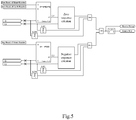
- Figure 4 is a block diagram of an apparatus of reactor turn-to-turn protection according to the present invention.
- the apparatus of reactor turn-to-turn protection comprising:
- the apparatus further comprising: an acquiring unit (not illustrated), adapted to acquire a phase voltage of high voltage end of the reactor and a phase current of low voltage end of the reactor and to determine the actual zero sequence voltage based on the phase voltage of high voltage end, and to determine the actual zero sequence current based on the phase current of low voltage end.
- an acquiring unit (not illustrated), adapted to acquire a phase voltage of high voltage end of the reactor and a phase current of low voltage end of the reactor and to determine the actual zero sequence voltage based on the phase voltage of high voltage end, and to determine the actual zero sequence current based on the phase current of low voltage end.
- the apparatus further comprising: an acquiring unit (not illustrated), adapted to acquire a phase voltage of high voltage end of the reactor and a phase current of low voltage end of the reactor and to determine the actual negative sequence voltage based on the phase voltage of high voltage end, to determine the actual negative sequence current based on the phase current of low voltage end.
- an acquiring unit (not illustrated), adapted to acquire a phase voltage of high voltage end of the reactor and a phase current of low voltage end of the reactor and to determine the actual negative sequence voltage based on the phase voltage of high voltage end, to determine the actual negative sequence current based on the phase current of low voltage end.
- the apparatus further comprising: an acquiring unit (not illustrated), adapted to acquire an open triangle zero sequence voltage of the high voltage as the actual zero sequence voltage, and to acquire a CT zero sequence current of the neutral point of the reactor as the actual zero sequence current.
- an acquiring unit (not illustrated), adapted to acquire an open triangle zero sequence voltage of the high voltage as the actual zero sequence voltage, and to acquire a CT zero sequence current of the neutral point of the reactor as the actual zero sequence current.
- the performing unit 403 adapted to judge whether the zero sequence operation quantity is greater than the zero sequence restraining quantity when the actual zero sequence voltage is greater than a predetermined zero sequence voltage threshold value, and performing the turn-to-turn protection when the zero sequence operation quantity is greater than the zero sequence restraining quantity.
- the performing unit 403 adapted to judge whether the zero sequence operation quantity is greater than the zero sequence restraining quantity when the actual zero sequence current is greater than a predetermined zero sequence current threshold value, and performing the turn-to-turn protection when the zero sequence operation quantity is greater than the zero sequence restraining quantity.
- the performing unit 403 adapted to judge whether the zero sequence operation quantity is greater than the zero sequence restraining quantity when the actual zero sequence current is greater than a predetermined zero sequence current threshold value and the actual zero sequence voltage is greater than a predetermined zero sequence voltage threshold value, and to perform the turn-to-turn protection when the zero sequence operation quantity is greater than the zero sequence restraining quantity.
- the performing unit 403 adapted to judge whether the negative sequence operation quantity is greater than the negative sequence restraining quantity when the actual negative sequence voltage is greater than a predetermined negative sequence voltage threshold value, and toperforme the turn-to-turn protection when the negative sequence operation quantity is greater than the negative sequence restraining quantity.
- the performing unit 403, adapted to judge whether the negative sequence operation quantity is greater than the negative sequence restraining quantity when the actual negative sequence current is greater than a predetermined negative sequence current threshold value, and performing the turn-to-turn protection when the negative sequence operation quantity is greater than the negative sequence restraining quantity; or Preferably, in one embodiment, the performing unit 403, adapted to judge whether the negative sequence operation quantity is greater than the negative sequence restraining quantity when the actual negative sequence current is greater than a predetermined negative sequence current threshold value and the actual negative sequence voltage is greater than a predetermined negative sequence voltage threshold value, and to perform the turn-to-turn protection when the negative sequence operation quantity is greater than the negative sequence restraining quantity.
- U o p .0
- U r e s .0
- U op .0 represents the zero sequence operation quantity,
- U res. 0 represents the zero sequence restraining quantity,
- U ⁇ 0 represents the actual zero sequence voltage,
- U • 0 ' represents the virtual zero sequence voltage.
- U op .2 represents the negative sequence operation quantity
- U res. 2 represents the negative sequence restraining quantity
- U • 2 represents the actual negative sequence voltage
- U 2 ' • represents the virtual negative sequence voltage.
- the virtual voltage determining unit adapted to calculate the virtual negative sequence voltage U • 2 ' ;
- U • 2 ' ⁇ I 2 f • Z L ;
- I • 2 f represents the actual negative sequence current,
- Z L represents phase reactance of the reactor
- Figure 5 shows a block diagram of an exemplary apparatus of reactor turn-to-turn protection according to the present invention.
- the apparatus of reactor turn-to-turn protection employs some gate circuits to perform a turn-to-turn protection. That is, a turn-to-turn protection action is performed when the zero sequence operation quantity is greater than the zero sequence restraining quantity or when the negative sequence operation quantity is greater than the negative sequence restraining quantity.
- an AND gate is respectively used in zero sequence criterion judgment and negative sequence criterion judgment to respectively limit the zero sequence voltage and zero sequence current.
- PSCAD / EMTDC simulation software has been used to simulate faults, normal and abnormal operating conditions.
- Establish the simulation model as shown in Figure 6 where the voltage and current are taken from the high voltage end of the reactor.
- the digital simulation software PSCAD / EMTDC does not have ready reactor model. Considering the difficulty of implement turn-to-turn faults and the approximation of actual reactor magnetic coupling relationship, the single-phase transformers are used to simulate the reactor in the digital simulation as shown in Figure 7 .
- phase A At 0.3 second, the phase A will have 50% turn-to-turn short circuit in the head, middle and end of the reactor respectively.
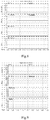
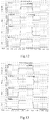
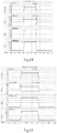
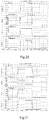
- the waveforms of relative zero and negative sequence voltages and operation quantity U op and restraint quantity U res obtained by simulation are shown in figure 10-11 , 12-13 and 14-15 .
- Waveforms of zero and negative sequence variables when 1.7% turn-to-turn short circuit occurred is shown in figure 16-17 , 18-19 and 20-21 .
- the proposed algorithm which directly compares the measured zero sequence voltage and calculated virtual zero sequence voltage, can identify the external fault, inter-turn fault and abnormal operation accurately in cooperated with the negative sequence protection criterion.
- the proposed principle is simple, intuitive, less affected by the variance of system operating mode and has higher sensitivity and reliability.
- the principle of the present invention is simple, intuitive, less affected by the variance of system operating mode and has higher sensitivity and reliability.
- the present invention can not only compare amplitudes, but also compare phases, which is an ideal inter-turn protection program for reactors.
Landscapes
- Engineering & Computer Science (AREA)
- Power Engineering (AREA)
- Physics & Mathematics (AREA)
- General Physics & Mathematics (AREA)
- Emergency Protection Circuit Devices (AREA)
- Protection Of Static Devices (AREA)
- Supply And Distribution Of Alternating Current (AREA)
Claims (12)
- Verfahren zum Reaktorwindungsschutz, umfassend:Bestimmen einer virtuellen Nullsystemspannung


 Bestimmen einer Nullsystembetriebsgröße (U op.0 ) und einer Nullsystemstabilisierungsgröße (U res.0 ) auf Basis einer tatsächlichen Nullsystemspannung


 Durchführen eines Windungsschutzes, wenn die Nullsystembetriebsgröße (Uop.0 ) größer ist als die Nullsystemstabilisierungsgröße (U res.0 ) und/oder wenn die Gegensystembetriebsgröße (Uop.2 ) größer ist als die Gegensystemstabilisierungsgröße (Ures.2 );Berechnen der virtuellen Nullsystemspannung

 Berechnen der virtuellen Gegensystemspannung


- Verfahren nach Anspruch 1, wobei umfassend:Erfassen einer Phasenspannung eines Hochspannungsendes des Reaktors und eines Phasenstroms des Niederspannungsendes des Reaktors;Bestimmen der tatsächlichen Nullsystemspannung


- Verfahren nach Anspruch 1, wobei umfassend:Erfassen einer Phasenspannung eines Hochspannungsendes des Reaktors und eines Phasenstroms des Niederspannungsendes des Reaktors;Bestimmen der tatsächlichen Gegensystemspannung


- Verfahren nach Anspruch 1, wobei umfassend:
Erfassen einer Offenes-Dreieck-Nullsystemspannung der Hochspannung als die tatsächliche Nullsystemspannung

- Verfahren nach Anspruch 1, wobei umfassend:Beurteilen, ob die Nullsystembetriebsgröße (U op.0) größer ist als die Nullsystemstabilisierungsgröße (U res.0), wenn die tatsächliche Nullsystemspannung
 Beurteilen, ob die Nullsystembetriebsgröße (U op.0) größer ist als die Nullsystemstabilisierungsgröße (U res.0), wenn der tatsächliche Nullsystemstrom
 Beurteilen, ob die Nullsystembetriebsgröße (U op.0) größer ist als die Nullsystemstabilisierungsgröße (U res.0), wenn der tatsächliche Nullsystemstrom

- Verfahren nach Anspruch 1, wobei umfassend:Beurteilen, ob die Gegensystembetriebsgröße (U op.2) größer ist als die Gegensystemstabilisierungsgröße (U res.2), wenn die tatsächliche Gegensystemspannung
 Beurteilen, ob die Gegensystembetriebsgröße (U op.2) größer ist als die Gegensystemstabilisierungsgröße (U res.2), wenn der tatsächliche Gegensystemstrom
 Beurteilen, ob die Gegensystembetriebsgröße (U op.2) größer ist als die Gegensystemstabilisierungsgröße (U res.2), wenn der tatsächliche Gegensystemstrom
- Vorrichtung für einen Reaktorwindungsschutz, umfassend:eine Virtuelle-Spannung-Bestimmungseinheit, ausgelegt zum Bestimmen einer virtuellen Nullsystemspannung


 eine Betriebsgrößen- und Stabilisierungsgrößenbestimmungseinheit, ausgelegt zum Bestimmen einer Nullsystembetriebsgröße (U op.0 ) und einer Nullsystemstabilisierungsgröße (Ures.0 ) auf Basis einer tatsächlichen Nullsystemspannung


 eine Durchführungseinheit, ausgelegt zum Durchführen eines Windungsschutzes, wenn die Nullsystembetriebsgröße (U op.0 ) größer ist als die Nullsystemstabilisierungsgröße (Ures.0 ), und/oder wenn die Gegensystembetriebsgröße (Uop.2 ) größer ist als die Gegensystemstabilisierungsgröße (U res.2 );die Virtuelle-Spannung-Bestimmungseinheit, ausgelegt zum Berechnen der virtuellen Nullsystemspannung
 die Virtuelle-Spannung-Bestimmungseinheit, weiterhin ausgelegt zum Berechnen der virtuellen Gegensystemspannung U 2;


- Vorrichtung nach Anspruch 7, weiterhin umfassend:
eine Erfassungseinheit, ausgelegt zum Erfassen einer Phasenspannung eines Hochspannungsendes des Reaktors und eines Phasenstroms des Niederspannungsendes des Reaktors, zum Bestimmen der tatsächlichen Nullsystemspannung

- Vorrichtung nach Anspruch 7, weiterhin umfassend:
eine Erfassungseinheit, ausgelegt zum Erfassen einer Phasenspannung eines Hochspannungsendes des Reaktors und eines Phasenstroms des Niederspannungsendes des Reaktors und zum Bestimmen der tatsächlichen Gegensystemspannung

- Vorrichtung nach Anspruch 7, weiterhin umfassend:
eine Erfassungseinheit, ausgelegt zum Erfassen einer Offenes-Dreieck-Nullsystemspannung der Hochspannung als die tatsächliche Nullsystemspannung

- Vorrichtung nach Anspruch 7, wobei
die Durchführungseinheit ausgelegt ist zum Beurteilen, ob die Nullsystembetriebsgröße (U op.0) größer ist als die Nullsystemstabilisierungsgröße (U res.0), wenn die tatsächliche Nullsystemspannung
Beurteilen, ob die Nullsystembetriebsgröße (U op.0) größer ist als die Nullsystemstabilisierungsgröße (U res.0), wenn der tatsächliche Nullsystemstrom
Beurteilen, ob die Nullsystembetriebsgröße (U op.0) größer ist als die Nullsystemstabilisierungsgröße (U res.0), wenn der tatsächliche Nullsystemstrom

- Vorrichtung nach Anspruch 7, wobei
die Durchführungseinheit ausgelegt ist zum: Beurteilen, ob die Gegensystembetriebsgröße (U op.2) größer ist als die Gegensystemstabilisierungsgröße (U res.2), wenn die tatsächliche Gegensystemspannung
Beurteilen, ob die Gegensystembetriebsgröße (U op.2) größer ist als die Gegensystemstabilisierungsgröße (U res.2), wenn der tatsächliche Gegensystemstrom
Beurteilen, ob die Gegensystembetriebsgröße (U op.2) größer ist als die Gegensystemstabilisierungsgröße (U res.2), wenn der tatsächliche Gegensystemstrom

Applications Claiming Priority (1)
| Application Number | Priority Date | Filing Date | Title |
|---|---|---|---|
| PCT/CN2013/087091 WO2015070407A1 (en) | 2013-11-13 | 2013-11-13 | Method and apparatus of reactor turn-to-turn protection |
Publications (3)
| Publication Number | Publication Date |
|---|---|
| EP3069426A1 EP3069426A1 (de) | 2016-09-21 |
| EP3069426A4 EP3069426A4 (de) | 2017-07-26 |
| EP3069426B1 true EP3069426B1 (de) | 2018-08-22 |
Family
ID=53056629
Family Applications (1)
| Application Number | Title | Priority Date | Filing Date |
|---|---|---|---|
| EP13897331.8A Active EP3069426B1 (de) | 2013-11-13 | 2013-11-13 | Verfahren und vorrichtung für einen reaktorwindungsschutz |
Country Status (3)
| Country | Link |
|---|---|
| EP (1) | EP3069426B1 (de) |
| CN (1) | CN105917539A (de) |
| WO (1) | WO2015070407A1 (de) |
Families Citing this family (26)
| Publication number | Priority date | Publication date | Assignee | Title |
|---|---|---|---|---|
| CN105006802B (zh) * | 2015-07-15 | 2017-10-31 | 南京国电南自电网自动化有限公司 | 基于电流比幅式序分量的电抗器保护方法 |
| US10088516B2 (en) * | 2016-02-10 | 2018-10-02 | General Electric Company | Systems and methods for detecting turn-to-turn faults in windings |
| CN106533239B (zh) * | 2016-12-13 | 2019-03-22 | 天津大学 | 具有自适应限流功能的三相四桥臂并网逆变器控制方法 |
| CN106786369B (zh) * | 2016-12-26 | 2018-12-28 | 云南电网有限责任公司电力科学研究院 | 基于有功功率的并联干式空心电抗器的保护方法 |
| CN106786368B (zh) * | 2016-12-26 | 2018-12-18 | 云南电网有限责任公司电力科学研究院 | 基于电压相位变化量的干式空心并联电抗器的保护方法 |
| CN109494683A (zh) * | 2018-11-16 | 2019-03-19 | 内蒙古电力勘测设计院有限责任公司 | 一种用于220kv线路限流电抗器的保护装置和方法 |
| CN109738739A (zh) * | 2018-12-20 | 2019-05-10 | 国网北京市电力公司 | 故障检测方法及装置 |
| CN109617016B (zh) * | 2018-12-27 | 2020-05-05 | 北京四方继保自动化股份有限公司 | 一种抽能绕组△型接线的抽能高抗抽能绕组匝间保护方法 |
| CN110912078B (zh) * | 2019-10-15 | 2022-07-01 | 中国电力科学研究院有限公司 | 一种串联变压器匝间故障环流定位方法及装置 |
| CN110867828B (zh) * | 2019-10-15 | 2022-09-02 | 中国电力科学研究院有限公司 | 一种抽能电抗器匝间故障的定位方法及装置 |
| CN110829367B (zh) * | 2019-12-16 | 2025-01-14 | 天津凯发电气股份有限公司 | 一种用于提高非电量保护可靠性的系统及方法 |
| CN111244893B (zh) * | 2020-01-20 | 2022-08-30 | 中国电力科学研究院有限公司 | 抽能电抗器匝间保护控制方法及装置 |
| CN111404118B (zh) * | 2020-03-27 | 2022-04-05 | 南京国电南自维美德自动化有限公司 | 一种纵向零序电压合成算法和匝间保护方法及装置 |
| CN113675819B (zh) * | 2020-05-14 | 2023-11-17 | 南京南瑞继保电气有限公司 | 电抗器的匝间保护方法、装置及电子设备 |
| CN111799757B (zh) * | 2020-05-25 | 2024-04-26 | 大唐国际发电股份有限公司陡河热电分公司 | 发电机纵向零序电压匝间保护方法 |
| CN112666376B (zh) * | 2020-12-29 | 2024-04-02 | 华能平凉发电有限责任公司 | 具有零序电流补偿功能的负序电流检测方法、系统及装置 |
| CN113937730B (zh) * | 2021-09-26 | 2024-07-05 | 长园深瑞继保自动化有限公司 | 匝间保护方法、装置及计算机设备 |
| CN114050551B (zh) * | 2021-11-04 | 2024-04-16 | 许继集团有限公司 | 一种并联电抗器保护方法及装置 |
| CN114050552B (zh) * | 2021-11-17 | 2023-09-15 | 许继集团有限公司 | 一种并联电抗器匝间保护方法及装置 |
| CN114397601A (zh) * | 2021-12-23 | 2022-04-26 | 广东电网有限责任公司 | 一种三相并联电抗器系统匝间短路的检测方法及装置 |
| CN114740313B (zh) * | 2022-03-30 | 2024-04-05 | 国网安徽省电力有限公司马鞍山供电公司 | 一种干式空心电抗器匝间绝缘缺陷检测系统及方法 |
| CN114879098B (zh) * | 2022-06-10 | 2024-09-24 | 华北电力大学 | 一种抽能型并联电抗器匝间故障判定方法及系统 |
| CN115032491B (zh) * | 2022-08-12 | 2022-11-01 | 国网山东省电力公司电力科学研究院 | 一种变压器非电量保护测试方法 |
| CN116247618B (zh) * | 2023-03-20 | 2024-08-16 | 南京国电南自电网自动化有限公司 | 一种防止并联电抗器低频振荡匝间保护误动的方法和系统 |
| CN119270133B (zh) * | 2024-10-11 | 2025-11-25 | 国网湖南省电力有限公司 | 一种干式电抗器匝间短路故障监测方法及系统 |
| CN119805204B (zh) * | 2024-11-29 | 2025-10-28 | 中国航发西安动力控制科技有限公司 | 一种电动燃油泵用永磁同步电机驱动系统的故障诊断装置 |
Family Cites Families (8)
| Publication number | Priority date | Publication date | Assignee | Title |
|---|---|---|---|---|
| SU678582A1 (ru) * | 1976-12-28 | 1979-08-05 | Челябинский Политехнический Институт Им.Ленинского Комсомола | Устройство дл защиты электроустановки с магнитопроводом от витковых замыканий |
| CN100362718C (zh) | 2003-12-24 | 2008-01-16 | 北京四方继保自动化有限公司 | 容错复判自适应高压并联电抗器匝间保护方法 |
| CN101071151B (zh) * | 2006-05-08 | 2010-04-21 | 许继集团有限公司 | 比幅式零序方向继电器测量电抗器匝间故障的方法 |
| CN101320908B (zh) * | 2008-03-27 | 2010-06-02 | 深圳南瑞科技有限公司 | 并联电抗器的匝间启动方法 |
| CN101614779B (zh) * | 2008-12-30 | 2011-01-26 | 许继集团有限公司 | 判别并联电抗器匝间短路、两相短路和单相短路的方法 |
| CN101819242A (zh) * | 2009-02-28 | 2010-09-01 | 浙江广天变压器有限公司 | 改进型电压差动对变压器匝间短路的检测装置 |
| CN101505051B (zh) | 2009-03-17 | 2011-04-13 | 国电南端科技股份有限公司 | 基于负序电压分布的发电机定子匝间短路保护方法 |
| CN101651328B (zh) * | 2009-08-20 | 2011-10-05 | 深圳南瑞科技有限公司 | 一种并联电抗器匝间保护方法及装置 |
-
2013
- 2013-11-13 EP EP13897331.8A patent/EP3069426B1/de active Active
- 2013-11-13 WO PCT/CN2013/087091 patent/WO2015070407A1/en not_active Ceased
- 2013-11-13 CN CN201380078834.8A patent/CN105917539A/zh active Pending
Non-Patent Citations (1)
| Title |
|---|
| None * |
Also Published As
| Publication number | Publication date |
|---|---|
| EP3069426A1 (de) | 2016-09-21 |
| EP3069426A4 (de) | 2017-07-26 |
| CN105917539A (zh) | 2016-08-31 |
| WO2015070407A1 (en) | 2015-05-21 |
Similar Documents
| Publication | Publication Date | Title |
|---|---|---|
| EP3069426B1 (de) | Verfahren und vorrichtung für einen reaktorwindungsschutz | |
| Liao et al. | Online optimal transmission line parameter estimation for relaying applications | |
| Chen et al. | A new adaptive PMU based protection scheme for transposed/untransposed parallel transmission lines | |
| CN104345197B (zh) | 在单相接地故障时估计零序电压的角度的方法及设备 | |
| CN101507072B (zh) | 接地故障检测装置、用于接地故障检测的方法和电气设备 | |
| EP2128951B1 (de) | Elektronisches aktives erdungssystem zur verwendung in hochspannungs-stromnetzen | |
| CN103782509A (zh) | 用于检测同步发电机内部绕组故障的系统、计算机程序产品和方法 | |
| CN108054764A (zh) | 一种多功能配电网柔性接地装置及控制方法 | |
| CN106569075A (zh) | 主变压器及高压侧电缆零序差动保护极性试验电路和方法 | |
| CN101237146A (zh) | 消弧线圈系统单相接地补偿状态在线监测及调控方法 | |
| CN103840437A (zh) | 配电网铁磁谐振与单相接地故障的快速诊断与处理方法 | |
| CN101860000A (zh) | 一种输电线路单相重合闸前的永久性故障快速识别方法 | |
| CN103293446A (zh) | 基于消弧线圈的小电流接地故障选线方法 | |
| CN104218526A (zh) | 采用分段相角补偿的发电机注入式定子接地保护方法 | |
| Xu et al. | A new fault-impedance algorithm for distance relaying on a transmission line | |
| CN106655121A (zh) | 一种微电网母线低阻抗自适应保护方法 | |
| Jiang et al. | A novel adaptive PMU-based transmission-line relay-design and EMTP simulation results | |
| CN107831378B (zh) | 一种检验消弧线圈补偿效果的装置及方法 | |
| Schlake et al. | Performance of third harmonic ground fault protection schemes for generator stator windings | |
| CN101877480A (zh) | 输电线路单相自适应重合闸的电压补偿判别方法 | |
| Wang et al. | Negative-sequence pilot protection with applications in open-phase transmission lines | |
| CN108051699A (zh) | 一种变电站互感器二次回路异常带电检测方法及系统 | |
| CN117538746A (zh) | 发电机机端pt一次绕组匝间短路故障在线监测及预警方法 | |
| CN113358978A (zh) | 一种配电网单相故障的故障类型辨识方法和装置 | |
| CN108107325A (zh) | 一种快速查找三相电压互感器故障的方法 |
Legal Events
| Date | Code | Title | Description |
|---|---|---|---|
| PUAI | Public reference made under article 153(3) epc to a published international application that has entered the european phase |
Free format text: ORIGINAL CODE: 0009012 |
|
| 17P | Request for examination filed |
Effective date: 20160513 |
|
| AK | Designated contracting states |
Kind code of ref document: A1 Designated state(s): AL AT BE BG CH CY CZ DE DK EE ES FI FR GB GR HR HU IE IS IT LI LT LU LV MC MK MT NL NO PL PT RO RS SE SI SK SM TR |
|
| AX | Request for extension of the european patent |
Extension state: BA ME |
|
| DAX | Request for extension of the european patent (deleted) | ||
| A4 | Supplementary search report drawn up and despatched |
Effective date: 20170626 |
|
| RIC1 | Information provided on ipc code assigned before grant |
Ipc: H02H 7/00 20060101AFI20170620BHEP |
|
| RAP1 | Party data changed (applicant data changed or rights of an application transferred) |
Owner name: SIEMENS AKTIENGESELLSCHAFT |
|
| GRAP | Despatch of communication of intention to grant a patent |
Free format text: ORIGINAL CODE: EPIDOSNIGR1 |
|
| INTG | Intention to grant announced |
Effective date: 20180319 |
|
| GRAS | Grant fee paid |
Free format text: ORIGINAL CODE: EPIDOSNIGR3 |
|
| GRAA | (expected) grant |
Free format text: ORIGINAL CODE: 0009210 |
|
| AK | Designated contracting states |
Kind code of ref document: B1 Designated state(s): AL AT BE BG CH CY CZ DE DK EE ES FI FR GB GR HR HU IE IS IT LI LT LU LV MC MK MT NL NO PL PT RO RS SE SI SK SM TR |
|
| REG | Reference to a national code |
Ref country code: GB Ref legal event code: FG4D |
|
| REG | Reference to a national code |
Ref country code: CH Ref legal event code: EP |
|
| REG | Reference to a national code |
Ref country code: AT Ref legal event code: REF Ref document number: 1033572 Country of ref document: AT Kind code of ref document: T Effective date: 20180915 |
|
| REG | Reference to a national code |
Ref country code: IE Ref legal event code: FG4D |
|
| REG | Reference to a national code |
Ref country code: DE Ref legal event code: R096 Ref document number: 602013042605 Country of ref document: DE |
|
| REG | Reference to a national code |
Ref country code: NL Ref legal event code: MP Effective date: 20180822 |
|
| REG | Reference to a national code |
Ref country code: LT Ref legal event code: MG4D |
|
| PG25 | Lapsed in a contracting state [announced via postgrant information from national office to epo] |
Ref country code: IS Free format text: LAPSE BECAUSE OF FAILURE TO SUBMIT A TRANSLATION OF THE DESCRIPTION OR TO PAY THE FEE WITHIN THE PRESCRIBED TIME-LIMIT Effective date: 20181222 Ref country code: RS Free format text: LAPSE BECAUSE OF FAILURE TO SUBMIT A TRANSLATION OF THE DESCRIPTION OR TO PAY THE FEE WITHIN THE PRESCRIBED TIME-LIMIT Effective date: 20180822 Ref country code: LT Free format text: LAPSE BECAUSE OF FAILURE TO SUBMIT A TRANSLATION OF THE DESCRIPTION OR TO PAY THE FEE WITHIN THE PRESCRIBED TIME-LIMIT Effective date: 20180822 Ref country code: NO Free format text: LAPSE BECAUSE OF FAILURE TO SUBMIT A TRANSLATION OF THE DESCRIPTION OR TO PAY THE FEE WITHIN THE PRESCRIBED TIME-LIMIT Effective date: 20181122 Ref country code: FI Free format text: LAPSE BECAUSE OF FAILURE TO SUBMIT A TRANSLATION OF THE DESCRIPTION OR TO PAY THE FEE WITHIN THE PRESCRIBED TIME-LIMIT Effective date: 20180822 Ref country code: GR Free format text: LAPSE BECAUSE OF FAILURE TO SUBMIT A TRANSLATION OF THE DESCRIPTION OR TO PAY THE FEE WITHIN THE PRESCRIBED TIME-LIMIT Effective date: 20181123 Ref country code: SE Free format text: LAPSE BECAUSE OF FAILURE TO SUBMIT A TRANSLATION OF THE DESCRIPTION OR TO PAY THE FEE WITHIN THE PRESCRIBED TIME-LIMIT Effective date: 20180822 Ref country code: NL Free format text: LAPSE BECAUSE OF FAILURE TO SUBMIT A TRANSLATION OF THE DESCRIPTION OR TO PAY THE FEE WITHIN THE PRESCRIBED TIME-LIMIT Effective date: 20180822 Ref country code: BG Free format text: LAPSE BECAUSE OF FAILURE TO SUBMIT A TRANSLATION OF THE DESCRIPTION OR TO PAY THE FEE WITHIN THE PRESCRIBED TIME-LIMIT Effective date: 20181122 |
|
| REG | Reference to a national code |
Ref country code: AT Ref legal event code: MK05 Ref document number: 1033572 Country of ref document: AT Kind code of ref document: T Effective date: 20180822 |
|
| PG25 | Lapsed in a contracting state [announced via postgrant information from national office to epo] |
Ref country code: LV Free format text: LAPSE BECAUSE OF FAILURE TO SUBMIT A TRANSLATION OF THE DESCRIPTION OR TO PAY THE FEE WITHIN THE PRESCRIBED TIME-LIMIT Effective date: 20180822 Ref country code: AL Free format text: LAPSE BECAUSE OF FAILURE TO SUBMIT A TRANSLATION OF THE DESCRIPTION OR TO PAY THE FEE WITHIN THE PRESCRIBED TIME-LIMIT Effective date: 20180822 Ref country code: HR Free format text: LAPSE BECAUSE OF FAILURE TO SUBMIT A TRANSLATION OF THE DESCRIPTION OR TO PAY THE FEE WITHIN THE PRESCRIBED TIME-LIMIT Effective date: 20180822 |
|
| PG25 | Lapsed in a contracting state [announced via postgrant information from national office to epo] |
Ref country code: RO Free format text: LAPSE BECAUSE OF FAILURE TO SUBMIT A TRANSLATION OF THE DESCRIPTION OR TO PAY THE FEE WITHIN THE PRESCRIBED TIME-LIMIT Effective date: 20180822 Ref country code: ES Free format text: LAPSE BECAUSE OF FAILURE TO SUBMIT A TRANSLATION OF THE DESCRIPTION OR TO PAY THE FEE WITHIN THE PRESCRIBED TIME-LIMIT Effective date: 20180822 Ref country code: CZ Free format text: LAPSE BECAUSE OF FAILURE TO SUBMIT A TRANSLATION OF THE DESCRIPTION OR TO PAY THE FEE WITHIN THE PRESCRIBED TIME-LIMIT Effective date: 20180822 Ref country code: PL Free format text: LAPSE BECAUSE OF FAILURE TO SUBMIT A TRANSLATION OF THE DESCRIPTION OR TO PAY THE FEE WITHIN THE PRESCRIBED TIME-LIMIT Effective date: 20180822 Ref country code: AT Free format text: LAPSE BECAUSE OF FAILURE TO SUBMIT A TRANSLATION OF THE DESCRIPTION OR TO PAY THE FEE WITHIN THE PRESCRIBED TIME-LIMIT Effective date: 20180822 Ref country code: EE Free format text: LAPSE BECAUSE OF FAILURE TO SUBMIT A TRANSLATION OF THE DESCRIPTION OR TO PAY THE FEE WITHIN THE PRESCRIBED TIME-LIMIT Effective date: 20180822 |
|
| REG | Reference to a national code |
Ref country code: DE Ref legal event code: R097 Ref document number: 602013042605 Country of ref document: DE |
|
| PG25 | Lapsed in a contracting state [announced via postgrant information from national office to epo] |
Ref country code: SK Free format text: LAPSE BECAUSE OF FAILURE TO SUBMIT A TRANSLATION OF THE DESCRIPTION OR TO PAY THE FEE WITHIN THE PRESCRIBED TIME-LIMIT Effective date: 20180822 Ref country code: DK Free format text: LAPSE BECAUSE OF FAILURE TO SUBMIT A TRANSLATION OF THE DESCRIPTION OR TO PAY THE FEE WITHIN THE PRESCRIBED TIME-LIMIT Effective date: 20180822 Ref country code: SM Free format text: LAPSE BECAUSE OF FAILURE TO SUBMIT A TRANSLATION OF THE DESCRIPTION OR TO PAY THE FEE WITHIN THE PRESCRIBED TIME-LIMIT Effective date: 20180822 |
|
| PLBE | No opposition filed within time limit |
Free format text: ORIGINAL CODE: 0009261 |
|
| REG | Reference to a national code |
Ref country code: CH Ref legal event code: PL |
|
| STAA | Information on the status of an ep patent application or granted ep patent |
Free format text: STATUS: NO OPPOSITION FILED WITHIN TIME LIMIT |
|
| 26N | No opposition filed |
Effective date: 20190523 |
|
| PG25 | Lapsed in a contracting state [announced via postgrant information from national office to epo] |
Ref country code: LU Free format text: LAPSE BECAUSE OF NON-PAYMENT OF DUE FEES Effective date: 20181113 Ref country code: MC Free format text: LAPSE BECAUSE OF FAILURE TO SUBMIT A TRANSLATION OF THE DESCRIPTION OR TO PAY THE FEE WITHIN THE PRESCRIBED TIME-LIMIT Effective date: 20180822 |
|
| REG | Reference to a national code |
Ref country code: BE Ref legal event code: MM Effective date: 20181130 |
|
| REG | Reference to a national code |
Ref country code: IE Ref legal event code: MM4A |
|
| PG25 | Lapsed in a contracting state [announced via postgrant information from national office to epo] |
Ref country code: LI Free format text: LAPSE BECAUSE OF NON-PAYMENT OF DUE FEES Effective date: 20181130 Ref country code: SI Free format text: LAPSE BECAUSE OF FAILURE TO SUBMIT A TRANSLATION OF THE DESCRIPTION OR TO PAY THE FEE WITHIN THE PRESCRIBED TIME-LIMIT Effective date: 20180822 Ref country code: CH Free format text: LAPSE BECAUSE OF NON-PAYMENT OF DUE FEES Effective date: 20181130 |
|
| PG25 | Lapsed in a contracting state [announced via postgrant information from national office to epo] |
Ref country code: IE Free format text: LAPSE BECAUSE OF NON-PAYMENT OF DUE FEES Effective date: 20181113 |
|
| PG25 | Lapsed in a contracting state [announced via postgrant information from national office to epo] |
Ref country code: BE Free format text: LAPSE BECAUSE OF NON-PAYMENT OF DUE FEES Effective date: 20181130 |
|
| PG25 | Lapsed in a contracting state [announced via postgrant information from national office to epo] |
Ref country code: MT Free format text: LAPSE BECAUSE OF NON-PAYMENT OF DUE FEES Effective date: 20181113 |
|
| PG25 | Lapsed in a contracting state [announced via postgrant information from national office to epo] |
Ref country code: TR Free format text: LAPSE BECAUSE OF FAILURE TO SUBMIT A TRANSLATION OF THE DESCRIPTION OR TO PAY THE FEE WITHIN THE PRESCRIBED TIME-LIMIT Effective date: 20180822 |
|
| PG25 | Lapsed in a contracting state [announced via postgrant information from national office to epo] |
Ref country code: PT Free format text: LAPSE BECAUSE OF FAILURE TO SUBMIT A TRANSLATION OF THE DESCRIPTION OR TO PAY THE FEE WITHIN THE PRESCRIBED TIME-LIMIT Effective date: 20180822 |
|
| PG25 | Lapsed in a contracting state [announced via postgrant information from national office to epo] |
Ref country code: MK Free format text: LAPSE BECAUSE OF NON-PAYMENT OF DUE FEES Effective date: 20180822 Ref country code: HU Free format text: LAPSE BECAUSE OF FAILURE TO SUBMIT A TRANSLATION OF THE DESCRIPTION OR TO PAY THE FEE WITHIN THE PRESCRIBED TIME-LIMIT; INVALID AB INITIO Effective date: 20131113 Ref country code: CY Free format text: LAPSE BECAUSE OF FAILURE TO SUBMIT A TRANSLATION OF THE DESCRIPTION OR TO PAY THE FEE WITHIN THE PRESCRIBED TIME-LIMIT Effective date: 20180822 |
|
| PGFP | Annual fee paid to national office [announced via postgrant information from national office to epo] |
Ref country code: DE Payment date: 20250120 Year of fee payment: 12 |
|
| PGFP | Annual fee paid to national office [announced via postgrant information from national office to epo] |
Ref country code: GB Payment date: 20251211 Year of fee payment: 13 |
|
| PGFP | Annual fee paid to national office [announced via postgrant information from national office to epo] |
Ref country code: IT Payment date: 20251125 Year of fee payment: 13 |
|
| PGFP | Annual fee paid to national office [announced via postgrant information from national office to epo] |
Ref country code: FR Payment date: 20251114 Year of fee payment: 13 |