EP3068710B1 - Slat for a conveyor - Google Patents
Slat for a conveyor Download PDFInfo
- Publication number
- EP3068710B1 EP3068710B1 EP14861192.4A EP14861192A EP3068710B1 EP 3068710 B1 EP3068710 B1 EP 3068710B1 EP 14861192 A EP14861192 A EP 14861192A EP 3068710 B1 EP3068710 B1 EP 3068710B1
- Authority
- EP
- European Patent Office
- Prior art keywords
- slat
- track
- slats
- wheel
- conveyor
- Prior art date
- Legal status (The legal status is an assumption and is not a legal conclusion. Google has not performed a legal analysis and makes no representation as to the accuracy of the status listed.)
- Active
Links
Images



Classifications
-
- B—PERFORMING OPERATIONS; TRANSPORTING
- B65—CONVEYING; PACKING; STORING; HANDLING THIN OR FILAMENTARY MATERIAL
- B65G—TRANSPORT OR STORAGE DEVICES, e.g. CONVEYORS FOR LOADING OR TIPPING, SHOP CONVEYOR SYSTEMS OR PNEUMATIC TUBE CONVEYORS
- B65G21/00—Supporting or protective framework or housings for endless load-carriers or traction elements of belt or chain conveyors
- B65G21/20—Means incorporated in, or attached to, framework or housings for guiding load-carriers, traction elements or loads supported on moving surfaces
- B65G21/22—Rails or the like engaging sliding elements or rollers attached to load-carriers or traction elements
-
- B—PERFORMING OPERATIONS; TRANSPORTING
- B65—CONVEYING; PACKING; STORING; HANDLING THIN OR FILAMENTARY MATERIAL
- B65G—TRANSPORT OR STORAGE DEVICES, e.g. CONVEYORS FOR LOADING OR TIPPING, SHOP CONVEYOR SYSTEMS OR PNEUMATIC TUBE CONVEYORS
- B65G17/00—Conveyors having an endless traction element, e.g. a chain, transmitting movement to a continuous or substantially-continuous load-carrying surface or to a series of individual load-carriers; Endless-chain conveyors in which the chains form the load-carrying surface
- B65G17/06—Conveyors having an endless traction element, e.g. a chain, transmitting movement to a continuous or substantially-continuous load-carrying surface or to a series of individual load-carriers; Endless-chain conveyors in which the chains form the load-carrying surface having a load-carrying surface formed by a series of interconnected, e.g. longitudinal, links, plates, or platforms
- B65G17/065—Conveyors having an endless traction element, e.g. a chain, transmitting movement to a continuous or substantially-continuous load-carrying surface or to a series of individual load-carriers; Endless-chain conveyors in which the chains form the load-carrying surface having a load-carrying surface formed by a series of interconnected, e.g. longitudinal, links, plates, or platforms the load carrying surface being formed by plates or platforms attached to a single traction element
- B65G17/066—Conveyors having an endless traction element, e.g. a chain, transmitting movement to a continuous or substantially-continuous load-carrying surface or to a series of individual load-carriers; Endless-chain conveyors in which the chains form the load-carrying surface having a load-carrying surface formed by a series of interconnected, e.g. longitudinal, links, plates, or platforms the load carrying surface being formed by plates or platforms attached to a single traction element specially adapted to follow a curved path
-
- B—PERFORMING OPERATIONS; TRANSPORTING
- B65—CONVEYING; PACKING; STORING; HANDLING THIN OR FILAMENTARY MATERIAL
- B65G—TRANSPORT OR STORAGE DEVICES, e.g. CONVEYORS FOR LOADING OR TIPPING, SHOP CONVEYOR SYSTEMS OR PNEUMATIC TUBE CONVEYORS
- B65G21/00—Supporting or protective framework or housings for endless load-carriers or traction elements of belt or chain conveyors
- B65G21/16—Supporting or protective framework or housings for endless load-carriers or traction elements of belt or chain conveyors for conveyors having endless load-carriers movable in curved paths
- B65G21/18—Supporting or protective framework or housings for endless load-carriers or traction elements of belt or chain conveyors for conveyors having endless load-carriers movable in curved paths in three-dimensionally curved paths
-
- B—PERFORMING OPERATIONS; TRANSPORTING
- B65—CONVEYING; PACKING; STORING; HANDLING THIN OR FILAMENTARY MATERIAL
- B65G—TRANSPORT OR STORAGE DEVICES, e.g. CONVEYORS FOR LOADING OR TIPPING, SHOP CONVEYOR SYSTEMS OR PNEUMATIC TUBE CONVEYORS
- B65G17/00—Conveyors having an endless traction element, e.g. a chain, transmitting movement to a continuous or substantially-continuous load-carrying surface or to a series of individual load-carriers; Endless-chain conveyors in which the chains form the load-carrying surface
- B65G17/06—Conveyors having an endless traction element, e.g. a chain, transmitting movement to a continuous or substantially-continuous load-carrying surface or to a series of individual load-carriers; Endless-chain conveyors in which the chains form the load-carrying surface having a load-carrying surface formed by a series of interconnected, e.g. longitudinal, links, plates, or platforms
- B65G17/08—Conveyors having an endless traction element, e.g. a chain, transmitting movement to a continuous or substantially-continuous load-carrying surface or to a series of individual load-carriers; Endless-chain conveyors in which the chains form the load-carrying surface having a load-carrying surface formed by a series of interconnected, e.g. longitudinal, links, plates, or platforms the surface being formed by the traction element
- B65G17/086—Conveyors having an endless traction element, e.g. a chain, transmitting movement to a continuous or substantially-continuous load-carrying surface or to a series of individual load-carriers; Endless-chain conveyors in which the chains form the load-carrying surface having a load-carrying surface formed by a series of interconnected, e.g. longitudinal, links, plates, or platforms the surface being formed by the traction element specially adapted to follow a curved path
-
- B—PERFORMING OPERATIONS; TRANSPORTING
- B65—CONVEYING; PACKING; STORING; HANDLING THIN OR FILAMENTARY MATERIAL
- B65G—TRANSPORT OR STORAGE DEVICES, e.g. CONVEYORS FOR LOADING OR TIPPING, SHOP CONVEYOR SYSTEMS OR PNEUMATIC TUBE CONVEYORS
- B65G17/00—Conveyors having an endless traction element, e.g. a chain, transmitting movement to a continuous or substantially-continuous load-carrying surface or to a series of individual load-carriers; Endless-chain conveyors in which the chains form the load-carrying surface
- B65G17/24—Conveyors having an endless traction element, e.g. a chain, transmitting movement to a continuous or substantially-continuous load-carrying surface or to a series of individual load-carriers; Endless-chain conveyors in which the chains form the load-carrying surface comprising a series of rollers which are moved, e.g. over a supporting surface, by the traction element to effect conveyance of loads or load-carriers
-
- B—PERFORMING OPERATIONS; TRANSPORTING
- B65—CONVEYING; PACKING; STORING; HANDLING THIN OR FILAMENTARY MATERIAL
- B65G—TRANSPORT OR STORAGE DEVICES, e.g. CONVEYORS FOR LOADING OR TIPPING, SHOP CONVEYOR SYSTEMS OR PNEUMATIC TUBE CONVEYORS
- B65G17/00—Conveyors having an endless traction element, e.g. a chain, transmitting movement to a continuous or substantially-continuous load-carrying surface or to a series of individual load-carriers; Endless-chain conveyors in which the chains form the load-carrying surface
- B65G17/30—Details; Auxiliary devices
-
- B—PERFORMING OPERATIONS; TRANSPORTING
- B65—CONVEYING; PACKING; STORING; HANDLING THIN OR FILAMENTARY MATERIAL
- B65G—TRANSPORT OR STORAGE DEVICES, e.g. CONVEYORS FOR LOADING OR TIPPING, SHOP CONVEYOR SYSTEMS OR PNEUMATIC TUBE CONVEYORS
- B65G21/00—Supporting or protective framework or housings for endless load-carriers or traction elements of belt or chain conveyors
- B65G21/20—Means incorporated in, or attached to, framework or housings for guiding load-carriers, traction elements or loads supported on moving surfaces
-
- B—PERFORMING OPERATIONS; TRANSPORTING
- B65—CONVEYING; PACKING; STORING; HANDLING THIN OR FILAMENTARY MATERIAL
- B65G—TRANSPORT OR STORAGE DEVICES, e.g. CONVEYORS FOR LOADING OR TIPPING, SHOP CONVEYOR SYSTEMS OR PNEUMATIC TUBE CONVEYORS
- B65G2207/00—Indexing codes relating to constructional details, configuration and additional features of a handling device, e.g. Conveyors
- B65G2207/44—Spiral conveyor tracks
-
- B—PERFORMING OPERATIONS; TRANSPORTING
- B65—CONVEYING; PACKING; STORING; HANDLING THIN OR FILAMENTARY MATERIAL
- B65G—TRANSPORT OR STORAGE DEVICES, e.g. CONVEYORS FOR LOADING OR TIPPING, SHOP CONVEYOR SYSTEMS OR PNEUMATIC TUBE CONVEYORS
- B65G2812/00—Indexing codes relating to the kind or type of conveyors
- B65G2812/02—Belt or chain conveyors
- B65G2812/02009—Common features for belt or chain conveyors
- B65G2812/02019—Supporting or guiding frames
- B65G2812/02069—Rails
-
- B—PERFORMING OPERATIONS; TRANSPORTING
- B65—CONVEYING; PACKING; STORING; HANDLING THIN OR FILAMENTARY MATERIAL
- B65G—TRANSPORT OR STORAGE DEVICES, e.g. CONVEYORS FOR LOADING OR TIPPING, SHOP CONVEYOR SYSTEMS OR PNEUMATIC TUBE CONVEYORS
- B65G2812/00—Indexing codes relating to the kind or type of conveyors
- B65G2812/02—Belt or chain conveyors
- B65G2812/02267—Conveyors having endless traction elements
- B65G2812/02415—Conveyors having endless traction elements with load-carrying surfaces supported by traction means
- B65G2812/02425—Continuous or uninterrupted load-carrying surfaces
- B65G2812/02455—Continuous or uninterrupted load-carrying surfaces the surfaces being above, between or beside the traction means
- B65G2812/02465—Continuous or uninterrupted load-carrying surfaces the surfaces being above, between or beside the traction means for conveyance along curves
Definitions
- the present invention relates to a conveyor utilizing a plurality of slats with the features of the preamble of claim 1. Furthermore, the invention relates to a plurality of slats and a slat for an endless carrier for use in such a conveyor.
- the current invention utilizes a novel and nonobvious endless carrier including slats having landing gears carrying wheels set apart from the slat, where the wheels are capable of engaging a surface distinctive from the landing gears.
- An aspect of a preferred embodiment of the current invention is to provide slats with landing gears including wheels.
- Another aspect of a preferred embodiment of the present invention is to provide an endless carrier for a conveyor where the combination of the slat, the landing gears and the wheels reduces friction encountered by the endless carrier as the endless carrier moves about the support supporting the endless carrier.
- Still another aspect of a preferred embodiment of the current invention is to provide slats with landing gears and wheels capable of reducing the weight-load resistance encountered by the endless carrier as the endless carrier moves articles over the article's transportation path.
- Another aspect of a preferred embodiment the present invention is to better distribute the various load stresses encountered by the slat across the length of slat rather than have the load stresses concentrated near the center-point of the slat.
- Still another aspect of a preferred embodiment of the present invention is to provide a stable slat whether the load is carried about the center of the slat or near the slat's lateral edges.
- Yet another aspect of a preferred embodiment of the present invention is to provide a landing gear that is integral with the slat.
- Another aspect of a preferred embodiment of the present invention is to provide landing gears that improve vertical stability of the slats whether the weight load is distributed proximate the slat's center or about the slat's lateral edges.
- Still another aspect of a preferred embodiment of the current invention is to simplify the structures required for restraining the tendency of the endless carrier to pull away from the endless carrier's support as the endless carrier moves through one or more curves associated with the conveyor's article transportation path.
- Yet another aspect of a preferred embodiment of the present invention is to provide a landing gear with a wheel capable of engaging the endless conveyor's support where the vertical and horizontal movement of the landing gear can be limited while rotational movement of the wheel is not limited.
- Still another aspect of a preferred embodiment of the present invention is to provide a landing gear/wheel combination that limits movement of the slat to a predetermined range for improving the slat's carrying performance and safe usage.
- a solution for these aspects is a conveyor with features of claim 1 as well as an endless plurality of slats according to claim 5. Further embodiments of the invention are described in the dependent claims.
- a preferred embodiment of the current invention can be described as a conveyor utilizing a plurality of slats; the conveyor comprising: a) a helical support comprising: i) a first track, wherein at least a portion of the first track spirals simultaneously with the helical support; ii) a second track, opposite the first track, wherein at least a portion of the second track spirals simultaneously with the helical support; and iii) a wall positioned between the first track and the second track; wherein at least a portion of the wall spirals simultaneously with the helical support; b) the plurality of slats traveling an endless pathway about the helical support; each slat having a superior article carrying side and an opposed side; wherein the opposed side further comprises: i) a first landing gear integral with the slat carrying a first wheel for engaging the first track, wherein vertical and horizontal movement but not rotational movement of the rotatable first wheel is limited by contact with the first track; and ii
- the current invention can be described as a conveyor utilizing a plurality of slats comprising: a) a support comprising: i) a first track routed about a first side of the support; and ii) a second track routed about a second side of the support; b) the plurality of slats defining a movable endless carrier traversing the support, wherein each slat has a superior article carrying side and an opposed side, and wherein the opposed side of each slat further comprises: i) a first landing gear carrying a first wheel for engaging the first track, wherein vertical and horizontal movement of the first wheel is limited by the first track; and ii) a second landing gear carrying a second wheel for engaging the second track, wherein vertical and horizontal movement of the second wheel is limited by the second track; and c) a drive driving the endless carrier.
- the current invention can be described as an endless plurality of slats driven about a support, wherein the support comprises a first track proximate a first side of the support and a second track proximate a second side of the support, wherein each of the plurality of slats comprises an article carrying side and an opposed side, and wherein one or more of the opposed sides comprises: a) a first landing gear carrying a first wheel for engaging the first track for limiting vertical and horizontal movement but not rotational movement of the first wheel; and b) a second landing gear carrying a second wheel for engaging the second track for limiting vertical and horizontal movement but not rotational movement of the first wheel.
- Yet another preferred embodiment of the current invention can be described as an endless plurality of slats driven about a support, wherein the support comprises a first track proximate a first side of the support and a second track proximate a second side of the support, wherein each of the plurality of slats comprises an article carrying side and an opposed side, and wherein one or more of the opposed sides comprises a first landing gear carrying a first wheel for engaging the first track and a second landing gear carrying a second wheel for engaging the second track.
- each of the plurality of slats comprises an article carrying side, an opposed side and a central transverse axis, and wherein one or more of the opposed sides comprises: a) a first landing gear carrying a first wheel set apart from the opposed side, wherein the first landing gear is located on a first side of the central transverse axis; and b) a second landing gear carrying a second wheel set apart from the opposed side, wherein the second landing gear is located on a second side of the central transverse axis.
- Yet another preferred embodiment of the current invention can be described as a slat for an endless carrier of a conveyor; the slat comprising a superior article carrying side and an opposed side, wherein the opposed side further comprises first and second landing gears carrying wheels traversing an approximate distance of an article transportation path and engaging opposed tracks associated with the article transportation path of the conveyor.
- Still another preferred embodiment of the current invention can be described as a slat for an endless loop traversing a conveyor; the slat comprising: a) a first side capable of carrying articles; b) a central transverse axis; and c) a second side opposite the first side; the second side comprising landing gears on opposed sides of the central transverse axis, wherein each landing gear further comprises a wheel set apart from the second side and capable of engaging a surface distinct from the landing gear.
- the present invention is a slat for a conveyor.
- Preferred embodiments of the current slat are compatible with a plethora of conveyors, including straight conveyors, curved conveyors as well as conveyors having both straight and curved sections.
- Preferred embodiments of the current slat can be attached together by any means acceptable in the art to form an endless loop that traverses about the conveyor.
- Each slat has a first side for carrying articles, a central transverse axis and a second side opposite the first side that is provided with landing gears on opposed sides of the central transverse axis.
- a wheel is set apart from the second side of the slat and carried by the landing gear such that the wheel is capable of engaging a surface that is distinct from the landing gear.
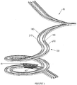
- FIG. 1 is an isometric view depicting a slat support (150) of conveyor (30) incorporating multiple curves, walls (180) and opposed tracks (210) for interacting with wheels associated with the slats' landing gears.
- Slat support (150), walls (180) and opposed tracks (210) are supported by any conveyor frame (not shown) acceptable in the art.
- the remaining slats (60) of endless carrier (40) have been cut away to reveal slat support (150).
- the FIG. 1 slat support (150) illustrates varying height, pitch, radius and direction.
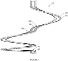
- FIG. 2 is an isometric view depicting a slat support (150) of conveyor (30) incorporating multiple curves, walls (180) and opposed tracks (210) for interacting with wheels associated with the slats' landing gears.
- Slat support (150), walls (180) and opposed tracks (210) are supported by any conveyor frame (not shown) acceptable in the art.
- the remaining slats (60) of endless carrier (40) have been cut away to reveal slat support (150).
- the FIG. 2 slat support (150) illustrates varying height, radius and direction.
- FIG. 3 is a top view depicting a slat support (150) of conveyor (30) incorporating multiple curves, walls (180) and opposed tracks (210) for interacting with wheels associated with the slats' landing gears.
- Slat support (150), walls (180) and opposed tracks (210) are supported by any conveyor frame (not shown) acceptable in the art.
- the remaining slats (60) of endless carrier (40) have been cut away to reveal slat support (150).
- the FIG. 3 slat support (150) illustrates varying height, radius and direction.
- FIG. 4 is a perspective of a spiral slat support (150) of conveyor (30) incorporating multiple curves, wall (180) and opposed tracks (210) for interacting with wheels associated with the slats' landing gears.
- Slat support (150), wall (180) and opposed tracks (210) are supported by any conveyor frame (not shown) acceptable in the art.
- the remaining slats (60) of endless carrier (40) have been cut away to reveal slat support (150).
- the FIG. 4 slat support (150) illustrates constant pitch, radius and direction.
- FIG. 5 is an isometric view of a helical slat support (150) of conveyor (30) incorporating multiple curves, wall (180) and opposed tracks (210) for interacting with wheels associated with the slats' landing gears.
- Slat support (150), wall (180) and opposed tracks (210) are supported by any conveyor frame (not shown) acceptable in the art.
- the remaining slats (60) of endless carrier (40) have been cut away to reveal slat support (150).
- the FIG. 5 slat support (150) illustrates constant pitch, radius and direction.
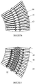
- FIG. 6 illustrates a preferred embodiment of slats (60) in accordance with the present invention.
- FIG. 6 is a top view of superior article carrying or first sides (66) of a section of slats (60) of endless carrier (40).
- FIG. 7 is a view of second or opposed sides (68) of a section of slats (60) of endless carrier (40).
- chain (90) interconnects opposed sides (68) of slats (60).
- Chain or interconnected links (90) can be driven by any drive (not shown in this view) acceptable in the art for driving endless carrier (40) about conveyor (30).
- preferred embodiments of the slats (60) and landing gears (80f, 80s) can be manufactured of high strength polymer or other synthetics.
- a preferred embodiment of a landing gear's wheel or wheels (82f, 82s) can include high precision sealed or unsealed bearings.
- select preferred embodiments of the current slats have: a thickness of about 3.2 centimeters; a length of about 61 centimeters; and a weight of about 340 grams.
- FIGS. 8 and 9 are rear views of preferred embodiments of slat (60) of endless carrier (40).
- Slat (60) includes superior side (66) and second side (68).
- second side (68) is superior to tracks (210f, 210s) receiving wheels (82f, 82s) carried by landing gears (80f, 80s) depending from second side (68) of slat (60).
- Landing gears (80f, 80s) can be integral with slat (60) or attached to slat (60) via any means acceptable in the art.
- wheels (82f, 82s) are carried by landing gears (80f, 80s) and are set apart from second side (68) of slat (60) such that wheels (82f, 82s) can engage a surface that is distinct from landing gears (80f, 80s) and slat (60). Further, in select preferred embodiments of endless carrier (40), it is not required that landing gears (80f, 80s) are attached to every slat (60) of endless carrier (40) for functionality of endless carrier (40).
- Preferred embodiments of tracks (210f, 210s) are provided with upper rails (212f, 212s), lower rails (214f, 214s) and connecting members (216f, 216s).
- the combination of upper rails (212f, 212s), lower rail (214f, 214s) and connecting member or connectors (216f, 216s) controls the vertical and horizontal movements but not the rotational movements of wheels (82f, 82s) of landing gear (80f, 80s).
- Construction of tracks (210f, 210s) in accordance with select preferred embodiments of the current invention allows tracks (210f, 210s) to capture wheels (82f, 82s) and enhances safer use of endless carrier (40).
- Select preferred embodiments of track (210) are provided with lower rail (214f, 214s) protectors (218f, 218s) for increasing the wearability of tracks (210f, 210s).
- clevis (100) carrying roller bearing (110) is attached to link (90).
- Roller bearing (110) engages wall (180) and assists endless carrier's (40) movement through a curve of conveyor (30).
- Preferred embodiments of the structures portrayed in FIG. 8 are generally used for conveyors having one or more curves only in a single direction.
- the attachment of a clevis (100) to each link is not required for functionality of link (90) of the chain within the scope of the current invention.
- a clevis is not required for functionality of endless carrier (40).
- FIG. 9 is a rear view of a preferred embodiment of slat (60) of endless carrier (40).
- two clevises (100f, 100s) carrying roller bearings (110f, 110s) are attached to opposed sides of chain (90).
- Each roller bearing (110f, 110s) engages a wall (180f, 180s) and assists endless carrier's (40) movement through curves of conveyor (30).
- Preferred embodiments of the structures portrayed in FIG. 9 are generally used for conveyors having curves in more than a single direction.
- clevises (100f, 100s) carrying roller bearings (110f, 110s) are attached to link (90) of chain. Roller bearings (110f, 110s) engage walls (180f, 180s) and assist endless carrier's (40) movement through curves of conveyor (30). Preferred embodiments of the structures portrayed in FIG. 9 are generally used for conveyors having curves in more than a single direction. Within the scope of the preferred embodiment disclosed in FIG. 9 , the attachment of a clevis (100f or 100s) to each link (90) is not required for functionality of endless carrier (40).
Landscapes
- Engineering & Computer Science (AREA)
- Mechanical Engineering (AREA)
- Chain Conveyers (AREA)
- Structure Of Belt Conveyors (AREA)
Description
- Among other things, the present invention relates to a conveyor utilizing a plurality of slats with the features of the preamble of claim 1. Furthermore, the invention relates to a plurality of slats and a slat for an endless carrier for use in such a conveyor.
- Any discussion of references cited in this Description of the Previous Art merely summarizes the disclosures of the cited references and Applicant makes no admission that any cited reference or portion thereof is relevant prior art. Applicant reserves the right to challenge the accuracy, relevancy and veracity of the cited references.
- 1)
EP 1 902 978 A1 /US Patent No. 7963389-Broers et al. enables a conveyor. This document discloses a conveyor with the features of the preamble of claim 1. Among other things, Broers does not disclose a slat comprising: a first side capable of carrying articles; a central transverse axis; and a second side opposite the first side comprising landing gears on opposed sides of the central transverse axis, where each landing gear further comprises a wheel set apart from the second side and capable of engaging a surface distinct from the landing gear. - 2)
DE 957 374 B-Dommann et al. discloses a conveyor with two rolls or wheels on the underside of the conveyor plate. The wheels have a profiled bearing surface. The wheel has a vertical rotational axis. On the outer side of the wheel is a rail which has a form which is adapted to the form of the bearing surface. - 3)
JP H 10-67424 A-YOSHIYUKI - 4)
JP 2002-29618 A- RYOSUKE - 5)
EP 1 097 885 A1-Mauri discloses a chain operated floor conveyor. A trolly is used for the conveyance of the parts to be handled. The wheels are mounted on crossbeams which are connected via an oscillation pin with a plate of the trolly. - 6)
US Patent No. 6336551-Balk enables a conveyor. Among other things, Balk does not disclose a slat comprising: a first side capable of carrying articles; a central transverse axis; and a second side opposite the first side comprising landing gears on opposed sides of the central transverse axis, where each landing gear further comprises a wheel set apart from the second side and capable of engaging a surface distinct from the landing gear. - 7)
US Patent No. 3627109-Cabak enables a conveyor construction. Among other things, Cabak does not disclose a slat comprising: a first side capable of carrying articles; a central transverse axis; and a second side opposite the first side comprising landing gears on opposed sides of the central transverse axis, where each landing gear further comprises a wheel set apart from the second side and capable of engaging a surface distinct from the landing gear. - 8)
US Patent No. 3826352-Van Zon, et al . enables a spiral column for endless chain conveyor. Among other things, Van Zon does not disclose a slat comprising: a first side capable of carrying articles; a central transverse axis; and a second side opposite the first side comprising landing gears on opposed sides of the central transverse axis, where each landing gear further comprises a wheel set apart from the second side and capable of engaging a surface distinct from the landing gear. - 9)
US Patent No. 5176247-Counter, et al . enables a sideplexing conveyor chain including low centerline hinge pin. Among other things, Counter does not disclose a slat comprising: a first side capable of carrying articles; a central transverse axis; and a second side opposite the first side comprising landing gears on opposed sides of the central transverse axis, where each landing gear further comprises a wheel set apart from the second side and capable of engaging a surface distinct from the landing gear. - 10)
US Patent No. 5775480-Lapeyre, et al . enables a low-friction conveyor assembly. Among other things, Lapeyre does not disclose a slat comprising: a first side capable of carrying articles; a central transverse axis; and a second side opposite the first side comprising landing gears on opposed sides of the central transverse axis, where each landing gear further comprises a wheel set apart from the second side and capable of engaging a surface distinct from the landing gear. - 11)
US Patent No. 7556142-Stebnicki, et al . enables a conveyor plate with integrated roller. Among other things, Stebnicki does not disclose a slat comprising: a first side capable of carrying articles; a central transverse axis; and a second side opposite the first side comprising landing gears on opposed sides of the central transverse axis, where each landing gear further comprises a wheel set apart from the second side and capable of engaging a surface distinct from the landing gear. - 12)
US Patent No. 7854315-Stebnicki, et al. enables a conveyor plate with integrated roller. The '315 Patent is a divisional Patent flowing fromUS Patent No. 7556142-Stebnicki, et al. Thus, the '315 Patent provides the same disclosure as the '142 Patent. - 13)
US Patent No. 4645070-Homeier enables a dual bend conveyor. Among other things, Homeier does not disclose a slat comprising: a first side capable of carrying articles; a central transverse axis; and a second side opposite the first side comprising landing gears on opposed sides of the central transverse axis, where each landing gear further comprises a wheel set apart from the second side and capable of engaging a surface distinct from the landing gear. - 14)
US Published Patent Application 20050150748-Zubair, et al. discloses a low-friction conveyor. Among other things, Zubair does not disclose a slat comprising: a first side capable of carrying articles; a central transverse axis; and a second side opposite the first side comprising landing gears on opposed sides of the central transverse axis, where each landing gear further comprises a wheel set apart from the second side and capable of engaging a surface distinct from the landing gear. - 15)
WO 2012154030-Ooi, B., et al. discloses a link for a conveyor chain, a conveyor chain made up of said links and a method of operation of said conveyor chain. Among other things, Ooi does not disclose a slat comprising: a first side capable of carrying articles; a central transverse axis; and a second side opposite the first side comprising landing gears on opposed sides of the central transverse axis, where each landing gear further comprises a wheel set apart from the second side and capable of engaging a surface distinct from the landing gear. - Unlike prior art systems, the current invention utilizes a novel and nonobvious endless carrier including slats having landing gears carrying wheels set apart from the slat, where the wheels are capable of engaging a surface distinctive from the landing gears.
- An aspect of a preferred embodiment of the current invention is to provide slats with landing gears including wheels.
- Another aspect of a preferred embodiment of the present invention is to provide an endless carrier for a conveyor where the combination of the slat, the landing gears and the wheels reduces friction encountered by the endless carrier as the endless carrier moves about the support supporting the endless carrier.
- Still another aspect of a preferred embodiment of the current invention is to provide slats with landing gears and wheels capable of reducing the weight-load resistance encountered by the endless carrier as the endless carrier moves articles over the article's transportation path.
- Another aspect of a preferred embodiment the present invention is to better distribute the various load stresses encountered by the slat across the length of slat rather than have the load stresses concentrated near the center-point of the slat.
- Still another aspect of a preferred embodiment of the present invention is to provide a stable slat whether the load is carried about the center of the slat or near the slat's lateral edges.
- Yet another aspect of a preferred embodiment of the present invention is to provide a landing gear that is integral with the slat.
- Another aspect of a preferred embodiment of the present invention is to provide landing gears that improve vertical stability of the slats whether the weight load is distributed proximate the slat's center or about the slat's lateral edges.
- Still another aspect of a preferred embodiment of the current invention is to simplify the structures required for restraining the tendency of the endless carrier to pull away from the endless carrier's support as the endless carrier moves through one or more curves associated with the conveyor's article transportation path.
- Yet another aspect of a preferred embodiment of the present invention is to provide a landing gear with a wheel capable of engaging the endless conveyor's support where the vertical and horizontal movement of the landing gear can be limited while rotational movement of the wheel is not limited.
- Still another aspect of a preferred embodiment of the present invention is to provide a landing gear/wheel combination that limits movement of the slat to a predetermined range for improving the slat's carrying performance and safe usage.
- A solution for these aspects is a conveyor with features of claim 1 as well as an endless plurality of slats according to claim 5. Further embodiments of the invention are described in the dependent claims.
- A preferred embodiment of the current invention can be described as a conveyor utilizing a plurality of slats; the conveyor comprising: a) a helical support comprising: i) a first track, wherein at least a portion of the first track spirals simultaneously with the helical support; ii) a second track, opposite the first track, wherein at least a portion of the second track spirals simultaneously with the helical support; and iii) a wall positioned between the first track and the second track; wherein at least a portion of the wall spirals simultaneously with the helical support; b) the plurality of slats traveling an endless pathway about the helical support; each slat having a superior article carrying side and an opposed side; wherein the opposed side further comprises: i) a first landing gear integral with the slat carrying a first wheel for engaging the first track, wherein vertical and horizontal movement but not rotational movement of the rotatable first wheel is limited by contact with the first track; and ii) a second landing gear integral with the slat carrying a second wheel for engaging the second track, wherein vertical and horizontal movement but not rotational movement of the second wheel is limited by contact with the second track; and c) a drive driving the plurality of slats.
- Another preferred embodiment the current invention can be described as a conveyor utilizing a plurality of slats comprising: a) a support comprising: i) a first track routed about a first side of the support; and ii) a second track routed about a second side of the support; b) the plurality of slats defining a movable endless carrier traversing the support, wherein each slat has a superior article carrying side and an opposed side, and wherein the opposed side of each slat further comprises: i) a first landing gear carrying a first wheel for engaging the first track, wherein vertical and horizontal movement of the first wheel is limited by the first track; and ii) a second landing gear carrying a second wheel for engaging the second track, wherein vertical and horizontal movement of the second wheel is limited by the second track; and c) a drive driving the endless carrier.
- Still another preferred embodiment the current invention can be described as an endless plurality of slats driven about a support, wherein the support comprises a first track proximate a first side of the support and a second track proximate a second side of the support, wherein each of the plurality of slats comprises an article carrying side and an opposed side, and wherein one or more of the opposed sides comprises: a) a first landing gear carrying a first wheel for engaging the first track for limiting vertical and horizontal movement but not rotational movement of the first wheel; and b) a second landing gear carrying a second wheel for engaging the second track for limiting vertical and horizontal movement but not rotational movement of the first wheel.
- Yet another preferred embodiment of the current invention can be described as an endless plurality of slats driven about a support, wherein the support comprises a first track proximate a first side of the support and a second track proximate a second side of the support, wherein each of the plurality of slats comprises an article carrying side and an opposed side, and wherein one or more of the opposed sides comprises a first landing gear carrying a first wheel for engaging the first track and a second landing gear carrying a second wheel for engaging the second track.
- Yet still another preferred embodiment of the current invention can be described as an endless plurality of slats driven about a support, wherein each of the plurality of slats comprises an article carrying side, an opposed side and a central transverse axis, and wherein one or more of the opposed sides comprises: a) a first landing gear carrying a first wheel set apart from the opposed side, wherein the first landing gear is located on a first side of the central transverse axis; and b) a second landing gear carrying a second wheel set apart from the opposed side, wherein the second landing gear is located on a second side of the central transverse axis.
- Yet another preferred embodiment of the current invention can be described as a slat for an endless carrier of a conveyor; the slat comprising a superior article carrying side and an opposed side, wherein the opposed side further comprises first and second landing gears carrying wheels traversing an approximate distance of an article transportation path and engaging opposed tracks associated with the article transportation path of the conveyor.
- Still another preferred embodiment of the current invention can be described as a slat for an endless loop traversing a conveyor; the slat comprising: a) a first side capable of carrying articles; b) a central transverse axis; and c) a second side opposite the first side; the second side comprising landing gears on opposed sides of the central transverse axis, wherein each landing gear further comprises a wheel set apart from the second side and capable of engaging a surface distinct from the landing gear.
-
-
FIG. 1 is an isometric view that shows a conveyor incorporating multiple curves and opposed tracks for interacting with wheels associated with the slats' landing gears. -
FIG. 2 is an isometric view that shows a conveyor incorporating multiple curves and opposed tracks for interacting with wheels associated with the slats' landing gears. -
FIG. 3 is a top view of a conveyor incorporating multiple curves and opposed tracks for interacting with wheels associated with the slats' landing gears. -
FIG.4 is a perspective of a spiral conveyor and opposed tracks for interacting with wheels associated with the slats' landing gears. -
FIG. 5 is an isometric view that shows a helical conveyor incorporating multiple curves and opposed tracks for interacting with wheels associated with the slats' landing gears. -
FIG. 6 illustrates a preferred embodiment of slats in accordance with the present invention. -
FIG. 7 is an view of the inferior sides of a section of slats of the endless carrier. -
FIG. 8 is a rear view of a preferred embodiment of a slat of the endless carrier. -
FIG. 9 is a rear view of a preferred embodiment of a slat of the endless carrier. - Among other things, the present invention is a slat for a conveyor. Preferred embodiments of the current slat are compatible with a plethora of conveyors, including straight conveyors, curved conveyors as well as conveyors having both straight and curved sections. Preferred embodiments of the current slat can be attached together by any means acceptable in the art to form an endless loop that traverses about the conveyor. Each slat has a first side for carrying articles, a central transverse axis and a second side opposite the first side that is provided with landing gears on opposed sides of the central transverse axis. A wheel is set apart from the second side of the slat and carried by the landing gear such that the wheel is capable of engaging a surface that is distinct from the landing gear.
- For many years, the conveyor industry has utilized conveyors with slats to move articles. Most of the prior art slats ride against the slat support and generate frictional resistance. Such friction forces decrease the efficiency of such conveying systems while simultaneously increasing the power consumption and wear and tear of such conveying systems.
- Some manufacturers of conveying slats have attempted to reduce frictional resistance by incorporating bearings into the slats. In such prior slat systems, the bearings contact the slat support at angles other than generally normal to the slat. The prior use of these radially located bearings requires the use of oversized bearings and decreases the efficiency of these systems. Because Applicants' landing gear/wheel combination is generally perpendicular to the slat, the current invention can pull greater package loads than the prior systems while the landing gear/wheel combination results in the present invention pulling lesser conveyor loads than prior systems. Through experimentation, the inventors have discovered that integral slat/landing gear/wheel combinations are well suited for the practice of the current invention. By way of example, integral slat/landing gear/wheel combinations have fewer parts to wear out and are easier to assemble and replace.
-
FIG. 1 is an isometric view depicting a slat support (150) of conveyor (30) incorporating multiple curves, walls (180) and opposed tracks (210) for interacting with wheels associated with the slats' landing gears. Slat support (150), walls (180) and opposed tracks (210) are supported by any conveyor frame (not shown) acceptable in the art. In this view, except for the section of slats (60) of endless carrier (40) illustrated inFIG. 1 , the remaining slats (60) of endless carrier (40) have been cut away to reveal slat support (150). Among other things, theFIG. 1 slat support (150) illustrates varying height, pitch, radius and direction. -
FIG. 2 is an isometric view depicting a slat support (150) of conveyor (30) incorporating multiple curves, walls (180) and opposed tracks (210) for interacting with wheels associated with the slats' landing gears. Slat support (150), walls (180) and opposed tracks (210) are supported by any conveyor frame (not shown) acceptable in the art. In this view, except for the section of slats (60) of endless carrier (40) illustrated inFIG. 2 , the remaining slats (60) of endless carrier (40) have been cut away to reveal slat support (150). Among other things, theFIG. 2 slat support (150) illustrates varying height, radius and direction. -
FIG. 3 is a top view depicting a slat support (150) of conveyor (30) incorporating multiple curves, walls (180) and opposed tracks (210) for interacting with wheels associated with the slats' landing gears. Slat support (150), walls (180) and opposed tracks (210) are supported by any conveyor frame (not shown) acceptable in the art. In this view, except for the section of slats (60) of endless carrier (40) illustrated inFIG. 3 , the remaining slats (60) of endless carrier (40) have been cut away to reveal slat support (150). Among other things, theFIG. 3 slat support (150) illustrates varying height, radius and direction. -
FIG. 4 is a perspective of a spiral slat support (150) of conveyor (30) incorporating multiple curves, wall (180) and opposed tracks (210) for interacting with wheels associated with the slats' landing gears. Slat support (150), wall (180) and opposed tracks (210) are supported by any conveyor frame (not shown) acceptable in the art. In this view, except for the section of slats (60) of endless carrier (40) illustrated inFIG. 4 , the remaining slats (60) of endless carrier (40) have been cut away to reveal slat support (150). Among other things, theFIG. 4 slat support (150) illustrates constant pitch, radius and direction. -
FIG. 5 is an isometric view of a helical slat support (150) of conveyor (30) incorporating multiple curves, wall (180) and opposed tracks (210) for interacting with wheels associated with the slats' landing gears. Slat support (150), wall (180) and opposed tracks (210) are supported by any conveyor frame (not shown) acceptable in the art. In this view, except for the section of slats (60) of endless carrier (40) illustrated inFIG. 5 , the remaining slats (60) of endless carrier (40) have been cut away to reveal slat support (150). Among other things, theFIG. 5 slat support (150) illustrates constant pitch, radius and direction. -
FIG. 6 illustrates a preferred embodiment of slats (60) in accordance with the present invention.FIG. 6 is a top view of superior article carrying or first sides (66) of a section of slats (60) of endless carrier (40).FIG. 7 is a view of second or opposed sides (68) of a section of slats (60) of endless carrier (40). As shown inFIG. 7 , chain (90) interconnects opposed sides (68) of slats (60). Chain or interconnected links (90) can be driven by any drive (not shown in this view) acceptable in the art for driving endless carrier (40) about conveyor (30). - Within the scope of the current invention, preferred embodiments of the slats (60) and landing gears (80f, 80s) can be manufactured of high strength polymer or other synthetics. A preferred embodiment of a landing gear's wheel or wheels (82f, 82s) can include high precision sealed or unsealed bearings. By way of example, select preferred embodiments of the current slats have: a thickness of about 3.2 centimeters; a length of about 61 centimeters; and a weight of about 340 grams.
-
FIGS. 8 and 9 are rear views of preferred embodiments of slat (60) of endless carrier (40). Slat (60) includes superior side (66) and second side (68). For the section of endless carrier (40) transporting articles, second side (68) is superior to tracks (210f, 210s) receiving wheels (82f, 82s) carried by landing gears (80f, 80s) depending from second side (68) of slat (60). Landing gears (80f, 80s) can be integral with slat (60) or attached to slat (60) via any means acceptable in the art. As shown, wheels (82f, 82s) are carried by landing gears (80f, 80s) and are set apart from second side (68) of slat (60) such that wheels (82f, 82s) can engage a surface that is distinct from landing gears (80f, 80s) and slat (60). Further, in select preferred embodiments of endless carrier (40), it is not required that landing gears (80f, 80s) are attached to every slat (60) of endless carrier (40) for functionality of endless carrier (40). - Preferred embodiments of tracks (210f, 210s) are provided with upper rails (212f, 212s), lower rails (214f, 214s) and connecting members (216f, 216s). The combination of upper rails (212f, 212s), lower rail (214f, 214s) and connecting member or connectors (216f, 216s) controls the vertical and horizontal movements but not the rotational movements of wheels (82f, 82s) of landing gear (80f, 80s). Construction of tracks (210f, 210s) in accordance with select preferred embodiments of the current invention allows tracks (210f, 210s) to capture wheels (82f, 82s) and enhances safer use of endless carrier (40). Select preferred embodiments of track (210) are provided with lower rail (214f, 214s) protectors (218f, 218s) for increasing the wearability of tracks (210f, 210s).
- As shown in the preferred embodiment of
FIG. 8 , clevis (100) carrying roller bearing (110) is attached to link (90). Roller bearing (110) engages wall (180) and assists endless carrier's (40) movement through a curve of conveyor (30). Preferred embodiments of the structures portrayed inFIG. 8 are generally used for conveyors having one or more curves only in a single direction. Within the scope of the preferred embodiment disclosed inFIG. 8 , the attachment of a clevis (100) to each link is not required for functionality of link (90) of the chain within the scope of the current invention. And for select conveyors, a clevis is not required for functionality of endless carrier (40). -
FIG. 9 is a rear view of a preferred embodiment of slat (60) of endless carrier (40). As shown in the preferred embodiment disclosed inFIG. 9 , two clevises (100f, 100s) carrying roller bearings (110f, 110s) are attached to opposed sides of chain (90). Each roller bearing (110f, 110s) engages a wall (180f, 180s) and assists endless carrier's (40) movement through curves of conveyor (30). Preferred embodiments of the structures portrayed inFIG. 9 are generally used for conveyors having curves in more than a single direction. - As shown in the preferred embodiment of
FIG. 9 , clevises (100f, 100s) carrying roller bearings (110f, 110s) are attached to link (90) of chain. Roller bearings (110f, 110s) engage walls (180f, 180s) and assist endless carrier's (40) movement through curves of conveyor (30). Preferred embodiments of the structures portrayed inFIG. 9 are generally used for conveyors having curves in more than a single direction. Within the scope of the preferred embodiment disclosed inFIG. 9 , the attachment of a clevis (100f or 100s) to each link (90) is not required for functionality of endless carrier (40).
Claims (8)
- A conveyor (30) utilizing a plurality of slats (60); said conveyor (30) comprising:a) a helical support (150) comprising:i) a first track (210f), wherein at least a portion of said first track (210f) spirals simultaneously with said helical support (150);ii) a second track (210s), opposite said first track (210f), wherein at least a portion of said second track (210s) spirals simultaneously with said helical support (150); andb) said plurality of slats (60) traveling an endless pathway about said helical support (150); each slat (60) having a superior article carrying side (66) and an opposed side (68); wherein said opposed side (68) further comprises:i) a first landing gear (80f) integral with said slat (60) carrying a first wheel (82f) for engaging said first track (210f), wherein vertical and horizontal movement but not rotational movement of said first wheel (82f) is limited by contact with said first track (210f); andii) a second landing gear (80s) integral with said slat (60) carrying a second wheel (82s) for engaging said second track (210s), wherein vertical and horizontal movement but not rotational movement of said second wheel (82s) is limited by contact with said second track (210s); andc) a drive driving said plurality of slats (60);
each of said tracks (210f, 210s) comprises an upper rail (212f, 212s) for said first and second wheels (82f, 82s), a lower rail (214f, 214s) for said first and second wheels (82f, 82s) and a connector (21 6f, 216s) extending between said upper rail (212f, 212s) and said lower rail (214f, 214s) and the combination of upper rails (212f, 212s), lower rails (214f, 214s) and connectors (216f, 216s) controls the vertical and horizontal movements but not the rotational movements of said wheels (82f, 82s) of said landing gears (80f, 80s);
the conveyer being characterized in that:the axis of rotation of the first wheel is parallel to the slat; andthe axis of rotation of the second wheel is parallel to the slat. - The conveyor of claim 1, further comprising:a chain of links (90) interconnecting said plurality of slats at the respective opposed sides (68), wherein the drive drives said plurality of slats via the chain of links (90);a wall (180) positioned between said first track (210f) and said second track (210s),wherein at least a portion of said wall (180) spirals simultaneously with said helical support (150); and each slat further comprising:
a clevis attached to a respective link of the chain of links (90) and carrying a roller bearing (110), which roller bearing (110) engages the wall (180). - The conveyor (30) of claim 1, wherein said landing gears (80f, 80s) are integral with said slat (60).
- The conveyor (30) of claim 1, wherein the first landing gear (80f) and the second landing gear (80s) are located on opposed sides of a central transverse axis of the slat (60).
- An endless plurality of slats (60) driven about a support (150), wherein said support (150) comprises a first track (210f) proximate a first side of said support (150) and a second track (210s) proximate a second side of said support (150), wherein each of said plurality of slats (60) comprises an article carrying side (66) and an opposed side (68), and wherein one or more of said opposed sides (68) comprises:a) a first landing gear (80f) carrying a first wheel (82f) for engaging an upper rail (212f) and a lower rail (214f) of said first track (210f), for limiting vertical and horizontal movement but not rotational movement of said first wheel (82f); andb) a second landing gear (80s) carrying a second wheel (82s) for engaging an upper rail (212s) and a lower rail (214s) of said second track (210s), for limiting vertical and horizontal movement but not rotational movement of said second wheel (82s);the endless plurality of slats being characterized in that:the axis of rotation of the first wheel is parallel to the slat; andthe axis of rotation of the second wheel is parallel to the slat.
- The endless plurality of slats of claim 5, wherein each of said tracks (210f, 210s) comprises an upper rail (212f, 212s), a lower rail (214f, 214s) and a connector (216f, 216s) extending between said upper rail (212f, 212s) and said lower rail (214f, 214s).
- The endless plurality of slats of claim 6, wherein said landing gears (80f, 80s) are integral with said slat (60).
- The endless plurality of slats of claim 5, wherein the first landing gear (80f) and the second landing gear (80s) are located on opposed sides of a central transverse axis of the slat (60).
Applications Claiming Priority (2)
| Application Number | Priority Date | Filing Date | Title |
|---|---|---|---|
| US201361902885P | 2013-11-12 | 2013-11-12 | |
| PCT/US2014/062331 WO2015073191A1 (en) | 2013-11-12 | 2014-10-27 | Slat for a conveyor |
Publications (3)
| Publication Number | Publication Date |
|---|---|
| EP3068710A1 EP3068710A1 (en) | 2016-09-21 |
| EP3068710A4 EP3068710A4 (en) | 2017-06-21 |
| EP3068710B1 true EP3068710B1 (en) | 2021-07-21 |
Family
ID=53057860
Family Applications (1)
| Application Number | Title | Priority Date | Filing Date |
|---|---|---|---|
| EP14861192.4A Active EP3068710B1 (en) | 2013-11-12 | 2014-10-27 | Slat for a conveyor |
Country Status (8)
| Country | Link |
|---|---|
| US (4) | US9731898B2 (en) |
| EP (1) | EP3068710B1 (en) |
| KR (2) | KR20160067871A (en) |
| CN (2) | CN105745166B (en) |
| AU (1) | AU2014349058B2 (en) |
| CA (2) | CA2927790C (en) |
| MX (2) | MX377681B (en) |
| WO (2) | WO2015073191A1 (en) |
Families Citing this family (9)
| Publication number | Priority date | Publication date | Assignee | Title |
|---|---|---|---|---|
| CA2927790C (en) * | 2013-11-12 | 2018-05-01 | Transnorm System, Inc. | Slat for a conveyor |
| NL2012475B1 (en) * | 2014-03-19 | 2016-01-08 | Ambaflex Int B V | Transporter for transporting goods in height. |
| NL2014054B1 (en) * | 2014-12-24 | 2016-10-12 | Ambaflex Int B V | Transporter. |
| KR101591425B1 (en) * | 2015-04-29 | 2016-02-12 | 한국공항공사 | Double sloping carousel |
| DE102017004820B3 (en) * | 2017-05-18 | 2018-09-27 | Interroll Holding Ag | Transport attachment, traction means, plate conveyor and method |
| CH714085A1 (en) * | 2017-08-28 | 2019-02-28 | Wrh Walter Reist Holding Ag | Conveyor system. |
| DE102018001569B4 (en) * | 2018-02-28 | 2019-10-31 | Interroll Holding Ag | Transport attachment, traction means, plate conveyor and method |
| EP4186826B1 (en) * | 2021-11-25 | 2024-04-03 | Ambaflex International B.V. | A helical conveyor |
| EP4361066A1 (en) * | 2022-10-26 | 2024-05-01 | Logi Concept Engineering B.V. | Conveyor belt |
Family Cites Families (48)
| Publication number | Priority date | Publication date | Assignee | Title |
|---|---|---|---|---|
| US2648423A (en) * | 1949-04-16 | 1953-08-11 | Theodore R Black | Endless belt conveyer |
| US2641354A (en) * | 1949-06-01 | 1953-06-09 | United Fruit Co | Banked conveyer |
| DE957374C (en) * | 1951-12-29 | 1957-01-31 | Gewerk Eisenhuette Westfalia | Rubber or steel link conveyor belt |
| US2850149A (en) * | 1955-11-17 | 1958-09-02 | Hewitt Robins Inc | Passenger conveyor |
| US2887209A (en) * | 1956-02-29 | 1959-05-19 | Swanson Tool & Machine Product | Straight line indexing unit |
| US3554360A (en) * | 1968-08-12 | 1971-01-12 | Seatech Engineering | Conveyor |
| US3627109A (en) | 1969-09-19 | 1971-12-14 | Richard E Cabak | Conveyor construction |
| US3826352A (en) | 1972-10-27 | 1974-07-30 | Rexnord Inc | Spiral column for endless chain conveyor |
| US3857476A (en) * | 1973-01-29 | 1974-12-31 | Theodore Equipment Corp | Helical endless-belt mechanisms for fuel or empty distray transporting and lifting |
| US3877567A (en) * | 1973-12-03 | 1975-04-15 | Ronald Sommerfield | Conveyor drive system |
| FR2383094A1 (en) | 1977-03-11 | 1978-10-06 | Barthelemy Louis | CONTINUOUS CARRIER |
| DE3408963A1 (en) | 1984-03-12 | 1985-09-19 | Liebherr-Verzahntechnik Gmbh, 8960 Kempten | TRANSPORT DEVICE FOR CONVEYING CARRIERS |
| CA1282028C (en) * | 1984-03-26 | 1991-03-26 | Stewart Systems, Inc. | Continuous proof and brake apparatus having improved conveyor system |
| US4729470A (en) * | 1984-03-26 | 1988-03-08 | Stewart Systems, Inc. | Continuous proofing and baking apparatus having improved conveyor system |
| US4645070A (en) | 1984-11-07 | 1987-02-24 | Pt Components, Inc. | Dual bend conveyor |
| CA1296671C (en) * | 1987-08-10 | 1992-03-03 | Gerald C. Roinestad | Conveyor belt and system with a non-collapsing inside edge |
| DE3928454A1 (en) * | 1989-08-29 | 1991-03-07 | Kampf Gmbh & Co Maschf | CLOCK AND TRANSPORT DEVICE |
| NO168520C (en) * | 1989-11-09 | 1992-03-04 | Merlin Teknologi As | HOSE AND CABLE TRANSPORT. |
| US5139135A (en) * | 1991-02-19 | 1992-08-18 | Guy Irwin | Reduced radius spiral conveyor with plastic belts |
| US5176247A (en) | 1991-08-12 | 1993-01-05 | Rexnord Corporation | Sideflexing conveyor chain including low centerline hinge pin |
| DE4224609A1 (en) * | 1992-07-25 | 1994-01-27 | Hauni Werke Koerber & Co Kg | Cigarette conveyor |
| US5394978A (en) * | 1993-09-29 | 1995-03-07 | G&T Conveyor Company, Inc. | Plate-type conveyor utilizing improved power applying means |
| IT234202Y1 (en) | 1994-11-08 | 2000-02-23 | Regina Sud Spa | CHAIN CONVEYOR WITH IMPROVED SLIDING FEATURES |
| US5620084A (en) | 1995-03-30 | 1997-04-15 | Jervis B. Webb Company | Chain propelled belt conveyor |
| GB2312487A (en) * | 1996-04-25 | 1997-10-29 | David John Cockayne | Conveyor Chain |
| US5775480A (en) | 1996-06-14 | 1998-07-07 | The Laitram Corporation | Low-friction conveyor assembly |
| JPH1067424A (en) | 1996-08-29 | 1998-03-10 | Tsubakimoto Chain Co | Carriage capable of coping with three-dimensional traveling and sorting device using same |
| DE19719008C1 (en) * | 1997-05-07 | 1998-11-26 | Dorma Gmbh & Co Kg | Drive for a guide rail with a partition wall or the like suspended from the drive |
| NL1006909C2 (en) * | 1997-09-02 | 1999-03-04 | Ambaflex B V | Transporter. |
| JP3448220B2 (en) * | 1998-07-29 | 2003-09-22 | 株式会社椿本チエイン | Slat conveyor chain |
| ATE261387T1 (en) * | 1998-10-20 | 2004-03-15 | Rexnord Marbett Spa | CONVEYOR CHAIN FOR CONVEYING ITEMS |
| IT1313921B1 (en) | 1999-11-05 | 2002-09-26 | Giardina Movimentazioni Ind S | CHAIN-OPERATED FLOOR CONVEYOR. |
| JP3622953B2 (en) | 2000-07-14 | 2005-02-23 | 株式会社椿本チエイン | Link frame connection mechanism of tray-type article transport device |
| JP3620022B2 (en) * | 2001-02-14 | 2005-02-16 | 山久チヱイン株式会社 | Chain for 3D transfer line |
| US7107899B2 (en) * | 2002-01-10 | 2006-09-19 | Nothum Jr Robert G | Spiral oven, heat delivery, enclosure and drive |
| DE60333376D1 (en) | 2002-05-30 | 2010-08-26 | Laitram Llc | FRICTION-FREE CONVEYOR |
| US7556142B2 (en) | 2005-11-30 | 2009-07-07 | Rexnord Industries, Llc | Conveyor plate with integrated roller |
| ES2425982T3 (en) * | 2006-09-25 | 2013-10-18 | Specialty Conveyor B.V. | Conveyor with curved trajectory |
| NL2000266C2 (en) | 2006-10-09 | 2008-04-10 | Specialty Conveyor Bv | Transporter for transporting and buffering general cargo. |
| WO2008072984A2 (en) * | 2006-12-12 | 2008-06-19 | Whisper Tech Limited | Linear-rotary motion conversion mechanism |
| IT1392467B1 (en) * | 2008-10-30 | 2012-03-09 | Rexnord Marbett Srl | CHAIN FOR CONVEYOR OF ARTICLES |
| DE102009035273B4 (en) * | 2009-07-29 | 2016-07-07 | Klotzki Maschinenbau Gmbh | Bowl feeders |
| WO2011146398A2 (en) | 2010-05-17 | 2011-11-24 | Globe Composite Solutions, Ltd | Slope plate carrousel carriage frame |
| US8490272B1 (en) | 2011-03-21 | 2013-07-23 | Transnorm System, Inc. | Merge/diverge conveying apparatus and method of providing a conveyor belt for a merge/diverge apparatus |
| MY172945A (en) | 2011-05-10 | 2019-12-16 | Flexmove System M Sdn Bhd | A link for a conveyor chain, a conveyor chain made up of said links and a method of operation of said conveyor chain |
| EP2644538B1 (en) | 2012-03-27 | 2015-02-25 | Specialty Conveyor B.V. | A conveyor |
| CA2927790C (en) * | 2013-11-12 | 2018-05-01 | Transnorm System, Inc. | Slat for a conveyor |
| NL2013073B1 (en) * | 2014-06-26 | 2016-07-11 | Specialty Conveyor Bv | Portal Accumulator. |
-
2014
- 2014-10-27 CA CA2927790A patent/CA2927790C/en active Active
- 2014-10-27 US US14/768,703 patent/US9731898B2/en active Active
- 2014-10-27 AU AU2014349058A patent/AU2014349058B2/en active Active
- 2014-10-27 KR KR1020167010452A patent/KR20160067871A/en not_active Ceased
- 2014-10-27 MX MX2016006122A patent/MX377681B/en active IP Right Grant
- 2014-10-27 MX MX2016006121A patent/MX367836B/en active IP Right Grant
- 2014-10-27 US US14/768,716 patent/US9561907B2/en active Active
- 2014-10-27 CA CA2927792A patent/CA2927792C/en active Active
- 2014-10-27 WO PCT/US2014/062331 patent/WO2015073191A1/en not_active Ceased
- 2014-10-27 WO PCT/US2014/062333 patent/WO2015073192A1/en not_active Ceased
- 2014-10-27 CN CN201480062074.6A patent/CN105745166B/en active Active
- 2014-10-27 EP EP14861192.4A patent/EP3068710B1/en active Active
- 2014-10-27 KR KR1020187037377A patent/KR102166880B1/en active Active
- 2014-10-27 CN CN201910323560.3A patent/CN109987380B/en active Active
-
2017
- 2017-08-06 US US15/669,938 patent/US10011429B2/en active Active
-
2018
- 2018-06-12 US US16/005,884 patent/US10421612B1/en active Active
Non-Patent Citations (1)
| Title |
|---|
| None * |
Also Published As
| Publication number | Publication date |
|---|---|
| CN105745166B (en) | 2019-04-19 |
| WO2015073191A1 (en) | 2015-05-21 |
| CA2927792A1 (en) | 2015-05-21 |
| US10011429B2 (en) | 2018-07-03 |
| MX2016006121A (en) | 2016-07-21 |
| MX2016006122A (en) | 2016-07-21 |
| US20160272430A1 (en) | 2016-09-22 |
| US10421612B1 (en) | 2019-09-24 |
| MX377681B (en) | 2025-03-04 |
| CA2927790A1 (en) | 2015-05-21 |
| CN105745166A (en) | 2016-07-06 |
| AU2014349058B2 (en) | 2017-10-05 |
| CA2927790C (en) | 2018-05-01 |
| US20170334652A1 (en) | 2017-11-23 |
| CA2927792C (en) | 2018-05-01 |
| US20160272431A1 (en) | 2016-09-22 |
| KR20190000404A (en) | 2019-01-02 |
| KR20160067871A (en) | 2016-06-14 |
| CN109987380B (en) | 2022-08-23 |
| CN109987380A (en) | 2019-07-09 |
| US9731898B2 (en) | 2017-08-15 |
| WO2015073192A1 (en) | 2015-05-21 |
| US9561907B2 (en) | 2017-02-07 |
| EP3068710A4 (en) | 2017-06-21 |
| MX367836B (en) | 2019-09-09 |
| KR102166880B1 (en) | 2020-10-19 |
| EP3068710A1 (en) | 2016-09-21 |
Similar Documents
| Publication | Publication Date | Title |
|---|---|---|
| CA2927790C (en) | Slat for a conveyor | |
| AU2014349058A1 (en) | Slat for a conveyor | |
| EP2039580B1 (en) | Carriage type conveyance device | |
| EP2343253B1 (en) | Conveyor plate with integrated roller | |
| US8011496B2 (en) | Conveyor means for articles | |
| US20070144991A1 (en) | Telescopic load-carrying device and method for the operation thereof | |
| CN107298370B (en) | Plate type conveying device | |
| KR20170129924A (en) | Automatic warehouse and hanging type stacker crane | |
| KR100511175B1 (en) | Conveyor for a load-moving system | |
| CN103863760A (en) | Chain conveyor | |
| EP4335787B1 (en) | Carrier basket transporter having carrier baskets with increased weight carrying capacity | |
| CN103415453A (en) | Conveying system, conveying element, and guide track | |
| CN107934439A (en) | It is a kind of to roll platform easy to adjust the conveying of height | |
| US9896271B1 (en) | Conveyor accumulator for controlling the flow of articles being conveyed | |
| US20050109579A1 (en) | Pallet conveyor | |
| EP2027046B1 (en) | Conveyor system | |
| US20240278995A1 (en) | Conveyor chain link and conveyor chain comprising such a chain link and conveyor system | |
| CN201209060Y (en) | Synchronous climbing conveyor | |
| EP3163265B1 (en) | Transport system suitable for transporting buckets in a combination weighing machine | |
| JP4090149B2 (en) | Conveyor for transporting the carrier | |
| HK40106540A (en) | Carrier basket support and stabilizing system for a carrier baskets transporter | |
| WO2014147582A1 (en) | Conveyer device for loading and unloading goods and/or luggage by means of carts |
Legal Events
| Date | Code | Title | Description |
|---|---|---|---|
| PUAI | Public reference made under article 153(3) epc to a published international application that has entered the european phase |
Free format text: ORIGINAL CODE: 0009012 |
|
| 17P | Request for examination filed |
Effective date: 20160513 |
|
| AK | Designated contracting states |
Kind code of ref document: A1 Designated state(s): AL AT BE BG CH CY CZ DE DK EE ES FI FR GB GR HR HU IE IS IT LI LT LU LV MC MK MT NL NO PL PT RO RS SE SI SK SM TR |
|
| AX | Request for extension of the european patent |
Extension state: BA ME |
|
| DAX | Request for extension of the european patent (deleted) | ||
| A4 | Supplementary search report drawn up and despatched |
Effective date: 20170523 |
|
| RIC1 | Information provided on ipc code assigned before grant |
Ipc: B65G 21/18 20060101AFI20170517BHEP |
|
| STAA | Information on the status of an ep patent application or granted ep patent |
Free format text: STATUS: EXAMINATION IS IN PROGRESS |
|
| 17Q | First examination report despatched |
Effective date: 20191205 |
|
| GRAP | Despatch of communication of intention to grant a patent |
Free format text: ORIGINAL CODE: EPIDOSNIGR1 |
|
| STAA | Information on the status of an ep patent application or granted ep patent |
Free format text: STATUS: GRANT OF PATENT IS INTENDED |
|
| INTG | Intention to grant announced |
Effective date: 20210210 |
|
| GRAS | Grant fee paid |
Free format text: ORIGINAL CODE: EPIDOSNIGR3 |
|
| GRAA | (expected) grant |
Free format text: ORIGINAL CODE: 0009210 |
|
| STAA | Information on the status of an ep patent application or granted ep patent |
Free format text: STATUS: THE PATENT HAS BEEN GRANTED |
|
| AK | Designated contracting states |
Kind code of ref document: B1 Designated state(s): AL AT BE BG CH CY CZ DE DK EE ES FI FR GB GR HR HU IE IS IT LI LT LU LV MC MK MT NL NO PL PT RO RS SE SI SK SM TR |
|
| REG | Reference to a national code |
Ref country code: GB Ref legal event code: FG4D |
|
| REG | Reference to a national code |
Ref country code: CH Ref legal event code: EP |
|
| REG | Reference to a national code |
Ref country code: DE Ref legal event code: R096 Ref document number: 602014078957 Country of ref document: DE |
|
| REG | Reference to a national code |
Ref country code: AT Ref legal event code: REF Ref document number: 1412425 Country of ref document: AT Kind code of ref document: T Effective date: 20210815 |
|
| REG | Reference to a national code |
Ref country code: IE Ref legal event code: FG4D |
|
| REG | Reference to a national code |
Ref country code: LT Ref legal event code: MG9D |
|
| REG | Reference to a national code |
Ref country code: NL Ref legal event code: MP Effective date: 20210721 |
|
| REG | Reference to a national code |
Ref country code: AT Ref legal event code: MK05 Ref document number: 1412425 Country of ref document: AT Kind code of ref document: T Effective date: 20210721 |
|
| PG25 | Lapsed in a contracting state [announced via postgrant information from national office to epo] |
Ref country code: RS Free format text: LAPSE BECAUSE OF FAILURE TO SUBMIT A TRANSLATION OF THE DESCRIPTION OR TO PAY THE FEE WITHIN THE PRESCRIBED TIME-LIMIT Effective date: 20210721 Ref country code: SE Free format text: LAPSE BECAUSE OF FAILURE TO SUBMIT A TRANSLATION OF THE DESCRIPTION OR TO PAY THE FEE WITHIN THE PRESCRIBED TIME-LIMIT Effective date: 20210721 Ref country code: HR Free format text: LAPSE BECAUSE OF FAILURE TO SUBMIT A TRANSLATION OF THE DESCRIPTION OR TO PAY THE FEE WITHIN THE PRESCRIBED TIME-LIMIT Effective date: 20210721 Ref country code: AT Free format text: LAPSE BECAUSE OF FAILURE TO SUBMIT A TRANSLATION OF THE DESCRIPTION OR TO PAY THE FEE WITHIN THE PRESCRIBED TIME-LIMIT Effective date: 20210721 Ref country code: BG Free format text: LAPSE BECAUSE OF FAILURE TO SUBMIT A TRANSLATION OF THE DESCRIPTION OR TO PAY THE FEE WITHIN THE PRESCRIBED TIME-LIMIT Effective date: 20211021 Ref country code: LT Free format text: LAPSE BECAUSE OF FAILURE TO SUBMIT A TRANSLATION OF THE DESCRIPTION OR TO PAY THE FEE WITHIN THE PRESCRIBED TIME-LIMIT Effective date: 20210721 Ref country code: PT Free format text: LAPSE BECAUSE OF FAILURE TO SUBMIT A TRANSLATION OF THE DESCRIPTION OR TO PAY THE FEE WITHIN THE PRESCRIBED TIME-LIMIT Effective date: 20211122 Ref country code: NL Free format text: LAPSE BECAUSE OF FAILURE TO SUBMIT A TRANSLATION OF THE DESCRIPTION OR TO PAY THE FEE WITHIN THE PRESCRIBED TIME-LIMIT Effective date: 20210721 Ref country code: NO Free format text: LAPSE BECAUSE OF FAILURE TO SUBMIT A TRANSLATION OF THE DESCRIPTION OR TO PAY THE FEE WITHIN THE PRESCRIBED TIME-LIMIT Effective date: 20211021 Ref country code: ES Free format text: LAPSE BECAUSE OF FAILURE TO SUBMIT A TRANSLATION OF THE DESCRIPTION OR TO PAY THE FEE WITHIN THE PRESCRIBED TIME-LIMIT Effective date: 20210721 Ref country code: FI Free format text: LAPSE BECAUSE OF FAILURE TO SUBMIT A TRANSLATION OF THE DESCRIPTION OR TO PAY THE FEE WITHIN THE PRESCRIBED TIME-LIMIT Effective date: 20210721 |
|
| PG25 | Lapsed in a contracting state [announced via postgrant information from national office to epo] |
Ref country code: PL Free format text: LAPSE BECAUSE OF FAILURE TO SUBMIT A TRANSLATION OF THE DESCRIPTION OR TO PAY THE FEE WITHIN THE PRESCRIBED TIME-LIMIT Effective date: 20210721 Ref country code: LV Free format text: LAPSE BECAUSE OF FAILURE TO SUBMIT A TRANSLATION OF THE DESCRIPTION OR TO PAY THE FEE WITHIN THE PRESCRIBED TIME-LIMIT Effective date: 20210721 Ref country code: GR Free format text: LAPSE BECAUSE OF FAILURE TO SUBMIT A TRANSLATION OF THE DESCRIPTION OR TO PAY THE FEE WITHIN THE PRESCRIBED TIME-LIMIT Effective date: 20211022 |
|
| REG | Reference to a national code |
Ref country code: DE Ref legal event code: R097 Ref document number: 602014078957 Country of ref document: DE |
|
| PG25 | Lapsed in a contracting state [announced via postgrant information from national office to epo] |
Ref country code: DK Free format text: LAPSE BECAUSE OF FAILURE TO SUBMIT A TRANSLATION OF THE DESCRIPTION OR TO PAY THE FEE WITHIN THE PRESCRIBED TIME-LIMIT Effective date: 20210721 |
|
| PLBE | No opposition filed within time limit |
Free format text: ORIGINAL CODE: 0009261 |
|
| STAA | Information on the status of an ep patent application or granted ep patent |
Free format text: STATUS: NO OPPOSITION FILED WITHIN TIME LIMIT |
|
| REG | Reference to a national code |
Ref country code: CH Ref legal event code: PL |
|
| PG25 | Lapsed in a contracting state [announced via postgrant information from national office to epo] |
Ref country code: SM Free format text: LAPSE BECAUSE OF FAILURE TO SUBMIT A TRANSLATION OF THE DESCRIPTION OR TO PAY THE FEE WITHIN THE PRESCRIBED TIME-LIMIT Effective date: 20210721 Ref country code: SK Free format text: LAPSE BECAUSE OF FAILURE TO SUBMIT A TRANSLATION OF THE DESCRIPTION OR TO PAY THE FEE WITHIN THE PRESCRIBED TIME-LIMIT Effective date: 20210721 Ref country code: RO Free format text: LAPSE BECAUSE OF FAILURE TO SUBMIT A TRANSLATION OF THE DESCRIPTION OR TO PAY THE FEE WITHIN THE PRESCRIBED TIME-LIMIT Effective date: 20210721 Ref country code: EE Free format text: LAPSE BECAUSE OF FAILURE TO SUBMIT A TRANSLATION OF THE DESCRIPTION OR TO PAY THE FEE WITHIN THE PRESCRIBED TIME-LIMIT Effective date: 20210721 Ref country code: CZ Free format text: LAPSE BECAUSE OF FAILURE TO SUBMIT A TRANSLATION OF THE DESCRIPTION OR TO PAY THE FEE WITHIN THE PRESCRIBED TIME-LIMIT Effective date: 20210721 Ref country code: AL Free format text: LAPSE BECAUSE OF FAILURE TO SUBMIT A TRANSLATION OF THE DESCRIPTION OR TO PAY THE FEE WITHIN THE PRESCRIBED TIME-LIMIT Effective date: 20210721 |
|
| REG | Reference to a national code |
Ref country code: BE Ref legal event code: MM Effective date: 20211031 |
|
| 26N | No opposition filed |
Effective date: 20220422 |
|
| PG25 | Lapsed in a contracting state [announced via postgrant information from national office to epo] |
Ref country code: MC Free format text: LAPSE BECAUSE OF FAILURE TO SUBMIT A TRANSLATION OF THE DESCRIPTION OR TO PAY THE FEE WITHIN THE PRESCRIBED TIME-LIMIT Effective date: 20210721 |
|
| PG25 | Lapsed in a contracting state [announced via postgrant information from national office to epo] |
Ref country code: LU Free format text: LAPSE BECAUSE OF NON-PAYMENT OF DUE FEES Effective date: 20211027 Ref country code: IT Free format text: LAPSE BECAUSE OF FAILURE TO SUBMIT A TRANSLATION OF THE DESCRIPTION OR TO PAY THE FEE WITHIN THE PRESCRIBED TIME-LIMIT Effective date: 20210721 Ref country code: BE Free format text: LAPSE BECAUSE OF NON-PAYMENT OF DUE FEES Effective date: 20211031 |
|
| PG25 | Lapsed in a contracting state [announced via postgrant information from national office to epo] |
Ref country code: LI Free format text: LAPSE BECAUSE OF NON-PAYMENT OF DUE FEES Effective date: 20211031 Ref country code: CH Free format text: LAPSE BECAUSE OF NON-PAYMENT OF DUE FEES Effective date: 20211031 |
|
| PG25 | Lapsed in a contracting state [announced via postgrant information from national office to epo] |
Ref country code: IE Free format text: LAPSE BECAUSE OF NON-PAYMENT OF DUE FEES Effective date: 20211027 |
|
| PG25 | Lapsed in a contracting state [announced via postgrant information from national office to epo] |
Ref country code: HU Free format text: LAPSE BECAUSE OF FAILURE TO SUBMIT A TRANSLATION OF THE DESCRIPTION OR TO PAY THE FEE WITHIN THE PRESCRIBED TIME-LIMIT; INVALID AB INITIO Effective date: 20141027 |
|
| PG25 | Lapsed in a contracting state [announced via postgrant information from national office to epo] |
Ref country code: CY Free format text: LAPSE BECAUSE OF FAILURE TO SUBMIT A TRANSLATION OF THE DESCRIPTION OR TO PAY THE FEE WITHIN THE PRESCRIBED TIME-LIMIT Effective date: 20210721 |
|
| PG25 | Lapsed in a contracting state [announced via postgrant information from national office to epo] |
Ref country code: MK Free format text: LAPSE BECAUSE OF FAILURE TO SUBMIT A TRANSLATION OF THE DESCRIPTION OR TO PAY THE FEE WITHIN THE PRESCRIBED TIME-LIMIT Effective date: 20210721 |
|
| PG25 | Lapsed in a contracting state [announced via postgrant information from national office to epo] |
Ref country code: MT Free format text: LAPSE BECAUSE OF FAILURE TO SUBMIT A TRANSLATION OF THE DESCRIPTION OR TO PAY THE FEE WITHIN THE PRESCRIBED TIME-LIMIT Effective date: 20210721 |
|
| PG25 | Lapsed in a contracting state [announced via postgrant information from national office to epo] |
Ref country code: TR Free format text: LAPSE BECAUSE OF FAILURE TO SUBMIT A TRANSLATION OF THE DESCRIPTION OR TO PAY THE FEE WITHIN THE PRESCRIBED TIME-LIMIT Effective date: 20210721 |
|
| PGFP | Annual fee paid to national office [announced via postgrant information from national office to epo] |
Ref country code: DE Payment date: 20251028 Year of fee payment: 12 |
|
| PGFP | Annual fee paid to national office [announced via postgrant information from national office to epo] |
Ref country code: GB Payment date: 20251023 Year of fee payment: 12 |
|
| PGFP | Annual fee paid to national office [announced via postgrant information from national office to epo] |
Ref country code: FR Payment date: 20251027 Year of fee payment: 12 |