EP3068661B1 - Mass transit vehicle chair - Google Patents
Mass transit vehicle chair Download PDFInfo
- Publication number
- EP3068661B1 EP3068661B1 EP14728665.2A EP14728665A EP3068661B1 EP 3068661 B1 EP3068661 B1 EP 3068661B1 EP 14728665 A EP14728665 A EP 14728665A EP 3068661 B1 EP3068661 B1 EP 3068661B1
- Authority
- EP
- European Patent Office
- Prior art keywords
- seat
- backrest
- frame
- axis
- base
- Prior art date
- Legal status (The legal status is an assumption and is not a legal conclusion. Google has not performed a legal analysis and makes no representation as to the accuracy of the status listed.)
- Active
Links
- 230000007246 mechanism Effects 0.000 description 4
- 230000008859 change Effects 0.000 description 3
- 230000009471 action Effects 0.000 description 2
- 238000010276 construction Methods 0.000 description 2
- 230000005484 gravity Effects 0.000 description 2
- 238000004873 anchoring Methods 0.000 description 1
- 238000010586 diagram Methods 0.000 description 1
- 230000000694 effects Effects 0.000 description 1
- 230000008030 elimination Effects 0.000 description 1
- 238000003379 elimination reaction Methods 0.000 description 1
- 210000004394 hip joint Anatomy 0.000 description 1
- 238000000034 method Methods 0.000 description 1
- 230000008569 process Effects 0.000 description 1
Images

Classifications
-
- B—PERFORMING OPERATIONS; TRANSPORTING
- B60—VEHICLES IN GENERAL
- B60N—SEATS SPECIALLY ADAPTED FOR VEHICLES; VEHICLE PASSENGER ACCOMMODATION NOT OTHERWISE PROVIDED FOR
- B60N2/00—Seats specially adapted for vehicles; Arrangement or mounting of seats in vehicles
- B60N2/02—Seats specially adapted for vehicles; Arrangement or mounting of seats in vehicles the seat or part thereof being movable, e.g. adjustable
- B60N2/04—Seats specially adapted for vehicles; Arrangement or mounting of seats in vehicles the seat or part thereof being movable, e.g. adjustable the whole seat being movable
- B60N2/16—Seats specially adapted for vehicles; Arrangement or mounting of seats in vehicles the seat or part thereof being movable, e.g. adjustable the whole seat being movable height-adjustable
- B60N2/18—Seats specially adapted for vehicles; Arrangement or mounting of seats in vehicles the seat or part thereof being movable, e.g. adjustable the whole seat being movable height-adjustable the front or the rear portion of the seat being adjustable, e.g. independently of each other
- B60N2/1807—Seats specially adapted for vehicles; Arrangement or mounting of seats in vehicles the seat or part thereof being movable, e.g. adjustable the whole seat being movable height-adjustable the front or the rear portion of the seat being adjustable, e.g. independently of each other characterised by the cinematic
- B60N2/181—Rods
-
- B—PERFORMING OPERATIONS; TRANSPORTING
- B60—VEHICLES IN GENERAL
- B60N—SEATS SPECIALLY ADAPTED FOR VEHICLES; VEHICLE PASSENGER ACCOMMODATION NOT OTHERWISE PROVIDED FOR
- B60N2/00—Seats specially adapted for vehicles; Arrangement or mounting of seats in vehicles
- B60N2/02—Seats specially adapted for vehicles; Arrangement or mounting of seats in vehicles the seat or part thereof being movable, e.g. adjustable
- B60N2/04—Seats specially adapted for vehicles; Arrangement or mounting of seats in vehicles the seat or part thereof being movable, e.g. adjustable the whole seat being movable
- B60N2/16—Seats specially adapted for vehicles; Arrangement or mounting of seats in vehicles the seat or part thereof being movable, e.g. adjustable the whole seat being movable height-adjustable
- B60N2/18—Seats specially adapted for vehicles; Arrangement or mounting of seats in vehicles the seat or part thereof being movable, e.g. adjustable the whole seat being movable height-adjustable the front or the rear portion of the seat being adjustable, e.g. independently of each other
- B60N2/1807—Seats specially adapted for vehicles; Arrangement or mounting of seats in vehicles the seat or part thereof being movable, e.g. adjustable the whole seat being movable height-adjustable the front or the rear portion of the seat being adjustable, e.g. independently of each other characterised by the cinematic
- B60N2/1839—Seats specially adapted for vehicles; Arrangement or mounting of seats in vehicles the seat or part thereof being movable, e.g. adjustable the whole seat being movable height-adjustable the front or the rear portion of the seat being adjustable, e.g. independently of each other characterised by the cinematic pivoting about an axis located in an intermediate position
-
- B—PERFORMING OPERATIONS; TRANSPORTING
- B60—VEHICLES IN GENERAL
- B60N—SEATS SPECIALLY ADAPTED FOR VEHICLES; VEHICLE PASSENGER ACCOMMODATION NOT OTHERWISE PROVIDED FOR
- B60N2/00—Seats specially adapted for vehicles; Arrangement or mounting of seats in vehicles
- B60N2/02—Seats specially adapted for vehicles; Arrangement or mounting of seats in vehicles the seat or part thereof being movable, e.g. adjustable
- B60N2/22—Seats specially adapted for vehicles; Arrangement or mounting of seats in vehicles the seat or part thereof being movable, e.g. adjustable the back-rest being adjustable
-
- B—PERFORMING OPERATIONS; TRANSPORTING
- B60—VEHICLES IN GENERAL
- B60N—SEATS SPECIALLY ADAPTED FOR VEHICLES; VEHICLE PASSENGER ACCOMMODATION NOT OTHERWISE PROVIDED FOR
- B60N2/00—Seats specially adapted for vehicles; Arrangement or mounting of seats in vehicles
- B60N2/24—Seats specially adapted for vehicles; Arrangement or mounting of seats in vehicles for particular purposes or particular vehicles
- B60N2/242—Bus seats
Definitions
- the subject of the invention if a mass transit vehicle chair, to be used in buses, vans, railway cars, aircraft and as seats of truck drivers, where it is necessary to change the position of the seat and backrest in the process of direct use by the passenger.
- the negative aspect of this movement is the spatial movement of "H" point within space.
- a chair with a variable seat inclination is presented, used in vehicles, offices and where a frequent change of seat position is required to adapt to the user's needs.
- the chair is characterised by the seat frame being placed on side connectors, mounted to the support mechanism in such a manner that the axis of rotation of the bolt, on which the seat frame is mounted is located approximately in a vertical axis, passing through the user's centre of gravity and is placed by the locking mechanism with a lock.
- variable backrest inclination vehicle chair used in long distance passenger transport vehicles.
- the chair is characterised by the fact that the frame, with shaped arms located in the recesses on the seat, placed on bolts mounted in supports, permanently connected with the base, whereas the ends of the arms are connected to the base with a connector.
- the vehicle seat which comprises: a seat frame a seat frame whose rear end portion is pivotally attached to a vehicle floor such that its front end portion can be raised and lowered, a backrest frame coupled to the rear end portion of the seat frame so as to be rotatable longitudinally; two linkage elements having a first end portion pivotally connected to a support piece on the right, respectively left, provided on the floor, and which are also engaged, at their central portion, with the front half-section of the seat frame; and a connecting bar for connecting the backrest frame with a second end portion linkage elements.
- the vehicle seat with a seat surface and a backrest which is pivotable about a transverse to the seat axis, preferably from an upright sitting position to an inclined rest position is pivotable, and with a height-adjustable via a height-adjusting head restraint, which has a top through an opening in the backrest engaging head cushion support and a head cushion, characterized in that the backrest an automatically operated tilt adjustment which is designed to adjust the headrest in a freely selectable position with the inclination adjustment within the backrest and the head cushion support by a in the backrest and arranged transversely to the seat surface extending pivot axis pivots.
- the essence of the invention which is a mass transit vehicle chair in the form of a seat, placed rotationally on a base and a rotationally placed reclining backrest on said base, with a given point "H" for said seat, wherein said base is permanently mounted to a floor and has a first horizontal axis perpendicular to the longitudinal axis of the vehicle on which a frame of said seat is rotationally placed, said frame is having in its front zone an axis mounted to an upper support which is connected by a common axis with a lower support which is placed in an articulated manner on an axis in said base, whereas both supports are connected at said common axis with one end of a pull rod, said pull rod is connected at an opposite end to an articulated joint at a lower arm of a backrest frame, said backrest frame is placed on a second horizontal axis which is placed on elements of said bas in parallel to said first horizontal axis, characterised in that said first horizontal axis is located at a distance "a" within 0.5 to 0.7,
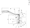
- the mass transit chair is composed of a seat 2 placed rotationally on frame 1 and a rotationally placed, reclined backrest 3.
- the chair has a base 4 fixed permanently to the floor 5.
- the upper support 8 and the lower support 11 on a common axis 9 are connected by a pull rod 12 end to an articulated joint 16 at the lower arm 13 of the backrest frame 14 of the reclining backrest 3.
- a reclining backrest 3 is placed on a horizontal axis 15, parallel to the first horizontal axis 6 of placement of frame 1 of the seat 2, at a constant distance from the characteristic point "H", near which the centre of gravity of the passenger in a normal sitting position is located.
- Chair base 4 elements are placed on the chair frame placement axis 6.
- the first horizontal axis 6 of the placement of frame 1 of the seat 2 is located at a distance "a" within 0.5 to 0.7, advantageously 0.6 of the length "A" of the frame 1 of the seat 2 from the front edge of the seat 2.
- the second horizontal axis 15 of the placement of frame 14 of the reclining backrest 3 is placed at a distance "b" within 0.05 to 0.15, advantageously 0.1 of the height "B" of the backrest frame 14 of the reclining backrest 3 from the lower edge of the backrest frame 14 of the reclining backrest 3.
- the natural shape of seat 2 will result in its shape being lowered towards the zone of connection with the reclining backrest 3.
Description
- The subject of the invention if a mass transit vehicle chair, to be used in buses, vans, railway cars, aircraft and as seats of truck drivers, where it is necessary to change the position of the seat and backrest in the process of direct use by the passenger.
- When constructing vehicle chairs, it is very important to establish the theoretical "H" point for each chair. This is a point which lies approximately at the height of the passenger's hip joint. The parameters of the chair, such as the length of the seat, backrest angle and anchoring points of safety belts are established in relation to this point. This point determines the construction of the entire chair. For each movement of the "H" point independent studies of chair structure should be conducted. Incorrectly adapted chair parameters in relation to the "H" point may result in the passenger sliding out from the seat belts during sudden braking, with all the negative consequences thereof.
- Long distance mass transit passenger chairs are known, where the seat is permanently placed in the base, and the backrest may be reclined by the placement of the backrest frame on the axis in the lower frame zone.
- Also chairs are known, where the seat frame and backrest frame are rigidly connected, whereas the movement of the seat and backrest when inclining the backrest has the same angle or a different backrest inclination angle, but with a simultaneous movement of the seat forward.
- The negative aspect of this movement is the spatial movement of "H" point within space.
- In the
PL 211142 B1 - In the
PL 205230 B1 - It is known from French application
FR 2569628 A1 - It is known from European application
EP 1346872 A1 the vehicle seat with a seat surface and a backrest, which is pivotable about a transverse to the seat axis, preferably from an upright sitting position to an inclined rest position is pivotable, and with a height-adjustable via a height-adjusting head restraint, which has a top through an opening in the backrest engaging head cushion support and a head cushion, characterized in that the backrest an automatically operated tilt adjustment which is designed to adjust the headrest in a freely selectable position with the inclination adjustment within the backrest and the head cushion support by a in the backrest and arranged transversely to the seat surface extending pivot axis pivots. - The essence of the invention, which is a mass transit vehicle chair in the form of a seat, placed rotationally on a base and a rotationally placed reclining backrest on said base, with a given point "H" for said seat, wherein said base is permanently mounted to a floor and has a first horizontal axis perpendicular to the longitudinal axis of the vehicle on which a frame of said seat is rotationally placed, said frame is having in its front zone an axis mounted to an upper support which is connected by a common axis with a lower support which is placed in an articulated manner on an axis in said base, whereas both supports are connected at said common axis with one end of a pull rod, said pull rod is connected at an opposite end to an articulated joint at a lower arm of a backrest frame, said backrest frame is placed on a second horizontal axis which is placed on elements of said bas in parallel to said first horizontal axis, characterised in that said first horizontal axis is located at a distance "a" within 0.5 to 0.7, advantageously 0.6 of the length "A" of said frame of said seat from the front edge of said seat and said second horizontal axis is located at a distance "b" within 0.05 to 0.15, advantageously 0.1 of the length "B" of said brackerst frame of the reclining backrest from the lower edge of said backrest frame of the reclining backrest.
- The use of the solution presented in the invention enables the following technical and utility effects:
- combination of the movement of raising the front of the seat and lowering the back of the seat with the backrest reclining movement.
- performing actions of changing the location of the seat and the backrest with one movement,
- the use of a single locking mechanism to change the location of the seat and chair,
- keeping the "H" point in the same area, which eliminates the necessity of conducting a cycle of studies for various locations of the seat,
- constant distance of the front edge of the seat from the chair mounted in front of it,
- possibility of moving the seat and backrest by any angle within the range of limiting values,
- possibility of changing the seat frame inclination angle other than the backrest frame inclination angle,
- reducing the unit weight by elimination of one locking mechanism,
- reducing the costs of construction.
- The subject of the invention, in an example, but not limiting, implementation was presented in diagrams on the figure, where on
fig. 1 the chair is presented in the position where the backrest is approximately vertical, and onfig. 2 the chair is presented in reclined backrest position, whereas on both figures additionally the theoretical "H" point is marked. - The mass transit chair is composed of a
seat 2 placed rotationally onframe 1 and a rotationally placed, reclinedbackrest 3. The chair has abase 4 fixed permanently to thefloor 5. On thebase 4, on the firsthorizontal axis 6, perpendicular to the longitudinal axis of the vehicle, theframe 1 of theseat 2 is placed. To theframe 1 in its front zone theaxis 7 mounted to theupper support 8 which is connected by thecommon axis 9 with alower support 11 which is placed in an articulated manner on theaxis 10 in thebase 4. Theupper support 8 and thelower support 11 on acommon axis 9 are connected by apull rod 12 end to an articulatedjoint 16 at thelower arm 13 of thebackrest frame 14 of the recliningbackrest 3. A recliningbackrest 3 is placed on ahorizontal axis 15, parallel to the firsthorizontal axis 6 of placement offrame 1 of theseat 2, at a constant distance from the characteristic point "H", near which the centre of gravity of the passenger in a normal sitting position is located.Chair base 4 elements are placed on the chairframe placement axis 6. - The first
horizontal axis 6 of the placement offrame 1 of theseat 2 is located at a distance "a" within 0.5 to 0.7, advantageously 0.6 of the length "A" of theframe 1 of theseat 2 from the front edge of theseat 2. - The second
horizontal axis 15 of the placement offrame 14 of the recliningbackrest 3 is placed at a distance "b" within 0.05 to 0.15, advantageously 0.1 of the height "B" of thebackrest frame 14 of the recliningbackrest 3 from the lower edge of thebackrest frame 14 of the recliningbackrest 3. - The chair in the position with the reclining
backrest 3 placed approximately vertically, has aseat 2 placed onframe 1, supported on the firshorizontal axis 6 andaxis 7, whereasframe 1 has an approximately horizontal position. The natural shape ofseat 2 will result in its shape being lowered towards the zone of connection with the recliningbackrest 3. - Release of the lock, not presented on the figure, and pressing the reclining
backrest 3 towards the back will result in thebackrest frame 14 of the recliningbackrest 3 moving on the secondhorizontal axis 15, resulting in the movement towards the front of thelower arm 13 of thebackrest frame 14. This will also cause the movement of the articulatedjoint 16 and pullrod 12 towards the front. A reciprocal movement of thelower support 11 andupper support 8 will occur. Due to the placement of thelower support 11 by one end in theaxis 10 in thebase 4 of the chair, an upwards movement of theaxis 7 of theupper support 8 will occur.Frame 1 of the chair will rotate by between ten and twenty degrees in relation to the firsthorizontal axis 6, lowering the back part of theseat 2 and raising the front part of theseat 2. - In the established position of the
seat 2 and the recliningbackrest 3 the position lock is closed. - Return of the
seat 2 and the recliningbackrest 3 to its primary position will occur after the lock is released. Then the recliningbackrest 3, when its upper part is moving towards the front, will result in thelower arm 13 of thebackrest frame 14 of the recliningbackrest 3 will move thepull rod 12 and thecommon axis 9 towards the back. Theaxis 7 of theframe 1 will move downwards, resulting in the rotation of theseat 2 of theframe 1 around the firsthorizontal axis 6, thus lowering the front part of theseat 2, and raising the rear part of theseat 2. After this action the position of elements is locked. - There is a possibility of using the same functions of reciprocal movement of the
seat 2 and the recliningbackrest 3 by raising the front part of theseat 2 upwards, or in a reverse case, pressing down on the front part of theseat 2. The kinematic system of connecting theseat 2 with the recliningbackrest 3 will result in the same movement as described above.
Claims (1)
- A mass transit vehicle chair in the form of a seat (2), placed rotationally on a base (4) and a rotationally placed reclining backrest (3) on said base (4), with a given point "H" for said seat, wherein said base (4) is permanently mounted to a floor (5), and has a first horizontal axis (6) perpendicular to the longitudinal axis of the vehicle on which a frame (1) of said seat (2) is rotationally placed, said frame (1) is having in its front zone an axis (7) mounted to an upper support (8) which is connected by a common axis (9) with a lower support (11) which is placed in an articulated manner on an axis (10) in said base (4), whereas both supports (8, 11) are connected at said common axis (9) with one end of a pull rod (12), said pull rod (12) is connected at an opposite end to an articulated joint (16) at a lower arm (13) of a backrest frame (14), said backrest frame (14) is placed on a second horizontal axis (15) which is placed on elements of said base (4) in parallel to said first horizontal axis (6), said first horizontal axis (6) is located at a distance "a" within 0.5 to 0.7, advantageously 0.6 of the length "A" of said frame (1) of said seat (2) from the front edge of said seat (2) and said second horizontal axis (15) is located at a distance "b" within 0.05 to 0.15, advantageously 0.1 of the length "B" of said backrest frame (14) of the reclining backrest (3) from the lower edge of said backrest frame (14) of the reclining backrest (3).
Applications Claiming Priority (2)
| Application Number | Priority Date | Filing Date | Title |
|---|---|---|---|
| PL406089A PL406089A1 (en) | 2013-11-15 | 2013-11-15 | Chair for the public communication vehicle |
| PCT/PL2014/000042 WO2015072867A1 (en) | 2013-11-15 | 2014-04-22 | Mass transit vehicle chair |
Publications (2)
| Publication Number | Publication Date |
|---|---|
| EP3068661A1 EP3068661A1 (en) | 2016-09-21 |
| EP3068661B1 true EP3068661B1 (en) | 2020-07-22 |
Family
ID=50896456
Family Applications (1)
| Application Number | Title | Priority Date | Filing Date |
|---|---|---|---|
| EP14728665.2A Active EP3068661B1 (en) | 2013-11-15 | 2014-04-22 | Mass transit vehicle chair |
Country Status (6)
| Country | Link |
|---|---|
| EP (1) | EP3068661B1 (en) |
| CN (1) | CN105899400B (en) |
| ES (1) | ES2819228T3 (en) |
| HK (1) | HK1223890A1 (en) |
| PL (1) | PL406089A1 (en) |
| WO (1) | WO2015072867A1 (en) |
Family Cites Families (8)
| Publication number | Priority date | Publication date | Assignee | Title |
|---|---|---|---|---|
| DE2836005A1 (en) * | 1978-08-17 | 1980-02-28 | Daimler Benz Ag | DEVICE FOR ADJUSTING A SEAT, IN PARTICULAR IN MOTOR VEHICLES |
| JPS6156609A (en) * | 1984-08-28 | 1986-03-22 | 株式会社タチエス | Seat for vehicle |
| FR2692529B1 (en) * | 1992-06-18 | 1994-09-16 | Faure Bertrand Automobile | Improvements to vehicle seats with multiple settings. |
| DE10209189A1 (en) * | 2002-03-04 | 2003-09-25 | Daimler Chrysler Ag | Vehicle seat with tilt-adjustable headrest |
| PL205230B1 (en) | 2003-06-18 | 2010-03-31 | Maciej Szymański | Vehicle seat |
| DE102006036532A1 (en) * | 2006-07-31 | 2008-02-07 | Sitech Sitztechnik Gmbh | Vehicle seat, has seat part rotating around rotation axis, where pelvic tilting of seat occurs within range of hip point by changing upward and backward rotation angles of seat part for correcting false position of lumbar spine |
| DE102007009170B4 (en) * | 2007-02-21 | 2014-10-30 | Johnson Controls Components Gmbh & Co. Kg | Vehicle seat, in particular commercial vehicle seat |
| PL211142B1 (en) | 2008-07-04 | 2012-04-30 | Maciej Szymański | Armchair |
-
2013
- 2013-11-15 PL PL406089A patent/PL406089A1/en unknown
-
2014
- 2014-04-22 EP EP14728665.2A patent/EP3068661B1/en active Active
- 2014-04-22 CN CN201480062365.5A patent/CN105899400B/en not_active Expired - Fee Related
- 2014-04-22 WO PCT/PL2014/000042 patent/WO2015072867A1/en active Application Filing
- 2014-04-22 ES ES14728665T patent/ES2819228T3/en active Active
-
2016
- 2016-10-24 HK HK16112170.9A patent/HK1223890A1/en not_active IP Right Cessation
Non-Patent Citations (1)
| Title |
|---|
| None * |
Also Published As
| Publication number | Publication date |
|---|---|
| CN105899400A (en) | 2016-08-24 |
| WO2015072867A1 (en) | 2015-05-21 |
| PL406089A1 (en) | 2015-05-25 |
| CN105899400B (en) | 2019-03-19 |
| HK1223890A1 (en) | 2017-08-11 |
| EP3068661A1 (en) | 2016-09-21 |
| ES2819228T3 (en) | 2021-04-15 |
Similar Documents
| Publication | Publication Date | Title |
|---|---|---|
| CN101578197B (en) | Stand up and kneel seat | |
| CN108528284B (en) | Seat back lifting mechanism for a recumbent motor vehicle seat assembly | |
| US8641141B2 (en) | Vehicle seat, scissors-type stand with force transmission | |
| CN106573553A (en) | Vehicle seat, in particular motor vehicle seat | |
| CN108528293B (en) | Mechanism for a recumbent motor vehicle seat assembly | |
| CN104670501B (en) | Passenger seat with bucket shape holder structure and adjustable position | |
| JP2016520470A (en) | Vehicle seat having simultaneous connection of seat pan and seat back | |
| JP2007507318A (en) | Reclining chair | |
| EP2694323B1 (en) | Adjustable seat | |
| CN101247972A (en) | Child safety seat | |
| US9649957B2 (en) | Second row vehicle seat | |
| JPH0197411A (en) | Seat and seat frame assembly | |
| US20160325837A1 (en) | Aircraft seat | |
| CN106627264B (en) | Foldable and overturned seat and automobile | |
| CN106379205B (en) | Vehicle seat mechanism and vehicle | |
| CN201313521Y (en) | Recliner for locomotive drivers | |
| JP4383333B2 (en) | wheelchair | |
| US20140239675A1 (en) | Furniture piece | |
| US9604553B2 (en) | Virtual H-point seat back system | |
| CN205836586U (en) | Multi-purpose vehicle(MPV) back seat | |
| EP3068661B1 (en) | Mass transit vehicle chair | |
| CN202966020U (en) | Two-purpose functional seat frame of automobile seat | |
| EP2587965B1 (en) | Second row package | |
| US8899684B2 (en) | Second row package | |
| CN208278064U (en) | A kind of cushion and the auto use chair for being equipped with the cushion |
Legal Events
| Date | Code | Title | Description |
|---|---|---|---|
| PUAI | Public reference made under article 153(3) epc to a published international application that has entered the european phase |
Free format text: ORIGINAL CODE: 0009012 |
|
| 17P | Request for examination filed |
Effective date: 20160323 |
|
| AK | Designated contracting states |
Kind code of ref document: A1 Designated state(s): AL AT BE BG CH CY CZ DE DK EE ES FI FR GB GR HR HU IE IS IT LI LT LU LV MC MK MT NL NO PL PT RO RS SE SI SK SM TR |
|
| AX | Request for extension of the european patent |
Extension state: BA ME |
|
| DAX | Request for extension of the european patent (deleted) | ||
| STAA | Information on the status of an ep patent application or granted ep patent |
Free format text: STATUS: EXAMINATION IS IN PROGRESS |
|
| 17Q | First examination report despatched |
Effective date: 20190507 |
|
| GRAP | Despatch of communication of intention to grant a patent |
Free format text: ORIGINAL CODE: EPIDOSNIGR1 |
|
| STAA | Information on the status of an ep patent application or granted ep patent |
Free format text: STATUS: GRANT OF PATENT IS INTENDED |
|
| INTG | Intention to grant announced |
Effective date: 20200506 |
|
| GRAS | Grant fee paid |
Free format text: ORIGINAL CODE: EPIDOSNIGR3 |
|
| GRAA | (expected) grant |
Free format text: ORIGINAL CODE: 0009210 |
|
| STAA | Information on the status of an ep patent application or granted ep patent |
Free format text: STATUS: THE PATENT HAS BEEN GRANTED |
|
| AK | Designated contracting states |
Kind code of ref document: B1 Designated state(s): AL AT BE BG CH CY CZ DE DK EE ES FI FR GB GR HR HU IE IS IT LI LT LU LV MC MK MT NL NO PL PT RO RS SE SI SK SM TR |
|
| REG | Reference to a national code |
Ref country code: GB Ref legal event code: FG4D |
|
| REG | Reference to a national code |
Ref country code: CH Ref legal event code: EP |
|
| REG | Reference to a national code |
Ref country code: DE Ref legal event code: R096 Ref document number: 602014067992 Country of ref document: DE |
|
| REG | Reference to a national code |
Ref country code: AT Ref legal event code: REF Ref document number: 1293086 Country of ref document: AT Kind code of ref document: T Effective date: 20200815 |
|
| REG | Reference to a national code |
Ref country code: IE Ref legal event code: FG4D |
|
| REG | Reference to a national code |
Ref country code: LT Ref legal event code: MG4D |
|
| REG | Reference to a national code |
Ref country code: AT Ref legal event code: MK05 Ref document number: 1293086 Country of ref document: AT Kind code of ref document: T Effective date: 20200722 |
|
| PG25 | Lapsed in a contracting state [announced via postgrant information from national office to epo] |
Ref country code: FI Free format text: LAPSE BECAUSE OF FAILURE TO SUBMIT A TRANSLATION OF THE DESCRIPTION OR TO PAY THE FEE WITHIN THE PRESCRIBED TIME-LIMIT Effective date: 20200722 Ref country code: AT Free format text: LAPSE BECAUSE OF FAILURE TO SUBMIT A TRANSLATION OF THE DESCRIPTION OR TO PAY THE FEE WITHIN THE PRESCRIBED TIME-LIMIT Effective date: 20200722 Ref country code: GR Free format text: LAPSE BECAUSE OF FAILURE TO SUBMIT A TRANSLATION OF THE DESCRIPTION OR TO PAY THE FEE WITHIN THE PRESCRIBED TIME-LIMIT Effective date: 20201023 Ref country code: NO Free format text: LAPSE BECAUSE OF FAILURE TO SUBMIT A TRANSLATION OF THE DESCRIPTION OR TO PAY THE FEE WITHIN THE PRESCRIBED TIME-LIMIT Effective date: 20201022 Ref country code: PT Free format text: LAPSE BECAUSE OF FAILURE TO SUBMIT A TRANSLATION OF THE DESCRIPTION OR TO PAY THE FEE WITHIN THE PRESCRIBED TIME-LIMIT Effective date: 20201123 Ref country code: SE Free format text: LAPSE BECAUSE OF FAILURE TO SUBMIT A TRANSLATION OF THE DESCRIPTION OR TO PAY THE FEE WITHIN THE PRESCRIBED TIME-LIMIT Effective date: 20200722 Ref country code: BG Free format text: LAPSE BECAUSE OF FAILURE TO SUBMIT A TRANSLATION OF THE DESCRIPTION OR TO PAY THE FEE WITHIN THE PRESCRIBED TIME-LIMIT Effective date: 20201022 Ref country code: LT Free format text: LAPSE BECAUSE OF FAILURE TO SUBMIT A TRANSLATION OF THE DESCRIPTION OR TO PAY THE FEE WITHIN THE PRESCRIBED TIME-LIMIT Effective date: 20200722 Ref country code: HR Free format text: LAPSE BECAUSE OF FAILURE TO SUBMIT A TRANSLATION OF THE DESCRIPTION OR TO PAY THE FEE WITHIN THE PRESCRIBED TIME-LIMIT Effective date: 20200722 |
|
| PG25 | Lapsed in a contracting state [announced via postgrant information from national office to epo] |
Ref country code: PL Free format text: LAPSE BECAUSE OF FAILURE TO SUBMIT A TRANSLATION OF THE DESCRIPTION OR TO PAY THE FEE WITHIN THE PRESCRIBED TIME-LIMIT Effective date: 20200722 Ref country code: LV Free format text: LAPSE BECAUSE OF FAILURE TO SUBMIT A TRANSLATION OF THE DESCRIPTION OR TO PAY THE FEE WITHIN THE PRESCRIBED TIME-LIMIT Effective date: 20200722 Ref country code: RS Free format text: LAPSE BECAUSE OF FAILURE TO SUBMIT A TRANSLATION OF THE DESCRIPTION OR TO PAY THE FEE WITHIN THE PRESCRIBED TIME-LIMIT Effective date: 20200722 Ref country code: IS Free format text: LAPSE BECAUSE OF FAILURE TO SUBMIT A TRANSLATION OF THE DESCRIPTION OR TO PAY THE FEE WITHIN THE PRESCRIBED TIME-LIMIT Effective date: 20201122 |
|
| PG25 | Lapsed in a contracting state [announced via postgrant information from national office to epo] |
Ref country code: NL Free format text: LAPSE BECAUSE OF FAILURE TO SUBMIT A TRANSLATION OF THE DESCRIPTION OR TO PAY THE FEE WITHIN THE PRESCRIBED TIME-LIMIT Effective date: 20200722 |
|
| REG | Reference to a national code |
Ref country code: ES Ref legal event code: FG2A Ref document number: 2819228 Country of ref document: ES Kind code of ref document: T3 Effective date: 20210415 |
|
| REG | Reference to a national code |
Ref country code: DE Ref legal event code: R097 Ref document number: 602014067992 Country of ref document: DE |
|
| PG25 | Lapsed in a contracting state [announced via postgrant information from national office to epo] |
Ref country code: IT Free format text: LAPSE BECAUSE OF FAILURE TO SUBMIT A TRANSLATION OF THE DESCRIPTION OR TO PAY THE FEE WITHIN THE PRESCRIBED TIME-LIMIT Effective date: 20200722 Ref country code: EE Free format text: LAPSE BECAUSE OF FAILURE TO SUBMIT A TRANSLATION OF THE DESCRIPTION OR TO PAY THE FEE WITHIN THE PRESCRIBED TIME-LIMIT Effective date: 20200722 Ref country code: DK Free format text: LAPSE BECAUSE OF FAILURE TO SUBMIT A TRANSLATION OF THE DESCRIPTION OR TO PAY THE FEE WITHIN THE PRESCRIBED TIME-LIMIT Effective date: 20200722 Ref country code: SM Free format text: LAPSE BECAUSE OF FAILURE TO SUBMIT A TRANSLATION OF THE DESCRIPTION OR TO PAY THE FEE WITHIN THE PRESCRIBED TIME-LIMIT Effective date: 20200722 Ref country code: RO Free format text: LAPSE BECAUSE OF FAILURE TO SUBMIT A TRANSLATION OF THE DESCRIPTION OR TO PAY THE FEE WITHIN THE PRESCRIBED TIME-LIMIT Effective date: 20200722 |
|
| PLBE | No opposition filed within time limit |
Free format text: ORIGINAL CODE: 0009261 |
|
| STAA | Information on the status of an ep patent application or granted ep patent |
Free format text: STATUS: NO OPPOSITION FILED WITHIN TIME LIMIT |
|
| PG25 | Lapsed in a contracting state [announced via postgrant information from national office to epo] |
Ref country code: AL Free format text: LAPSE BECAUSE OF FAILURE TO SUBMIT A TRANSLATION OF THE DESCRIPTION OR TO PAY THE FEE WITHIN THE PRESCRIBED TIME-LIMIT Effective date: 20200722 |
|
| 26N | No opposition filed |
Effective date: 20210423 |
|
| PG25 | Lapsed in a contracting state [announced via postgrant information from national office to epo] |
Ref country code: SK Free format text: LAPSE BECAUSE OF FAILURE TO SUBMIT A TRANSLATION OF THE DESCRIPTION OR TO PAY THE FEE WITHIN THE PRESCRIBED TIME-LIMIT Effective date: 20200722 |
|
| PG25 | Lapsed in a contracting state [announced via postgrant information from national office to epo] |
Ref country code: SI Free format text: LAPSE BECAUSE OF FAILURE TO SUBMIT A TRANSLATION OF THE DESCRIPTION OR TO PAY THE FEE WITHIN THE PRESCRIBED TIME-LIMIT Effective date: 20200722 |
|
| REG | Reference to a national code |
Ref country code: NL Ref legal event code: MP Effective date: 20200722 |
|
| REG | Reference to a national code |
Ref country code: DE Ref legal event code: R119 Ref document number: 602014067992 Country of ref document: DE |
|
| PG25 | Lapsed in a contracting state [announced via postgrant information from national office to epo] |
Ref country code: MC Free format text: LAPSE BECAUSE OF FAILURE TO SUBMIT A TRANSLATION OF THE DESCRIPTION OR TO PAY THE FEE WITHIN THE PRESCRIBED TIME-LIMIT Effective date: 20200722 |
|
| GBPC | Gb: european patent ceased through non-payment of renewal fee |
Effective date: 20210422 |
|
| PG25 | Lapsed in a contracting state [announced via postgrant information from national office to epo] |
Ref country code: LU Free format text: LAPSE BECAUSE OF NON-PAYMENT OF DUE FEES Effective date: 20210422 |
|
| REG | Reference to a national code |
Ref country code: BE Ref legal event code: MM Effective date: 20210430 |
|
| PG25 | Lapsed in a contracting state [announced via postgrant information from national office to epo] |
Ref country code: DE Free format text: LAPSE BECAUSE OF NON-PAYMENT OF DUE FEES Effective date: 20211103 Ref country code: CZ Free format text: LAPSE BECAUSE OF NON-PAYMENT OF DUE FEES Effective date: 20210422 Ref country code: GB Free format text: LAPSE BECAUSE OF NON-PAYMENT OF DUE FEES Effective date: 20210422 Ref country code: FR Free format text: LAPSE BECAUSE OF NON-PAYMENT OF DUE FEES Effective date: 20210430 Ref country code: CH Free format text: LAPSE BECAUSE OF NON-PAYMENT OF DUE FEES Effective date: 20210430 Ref country code: LI Free format text: LAPSE BECAUSE OF NON-PAYMENT OF DUE FEES Effective date: 20210430 |
|
| PG25 | Lapsed in a contracting state [announced via postgrant information from national office to epo] |
Ref country code: IE Free format text: LAPSE BECAUSE OF NON-PAYMENT OF DUE FEES Effective date: 20210422 |
|
| PG25 | Lapsed in a contracting state [announced via postgrant information from national office to epo] |
Ref country code: IS Free format text: LAPSE BECAUSE OF FAILURE TO SUBMIT A TRANSLATION OF THE DESCRIPTION OR TO PAY THE FEE WITHIN THE PRESCRIBED TIME-LIMIT Effective date: 20201122 |
|
| REG | Reference to a national code |
Ref country code: ES Ref legal event code: FD2A Effective date: 20220727 |
|
| PG25 | Lapsed in a contracting state [announced via postgrant information from national office to epo] |
Ref country code: BE Free format text: LAPSE BECAUSE OF NON-PAYMENT OF DUE FEES Effective date: 20210430 |
|
| PG25 | Lapsed in a contracting state [announced via postgrant information from national office to epo] |
Ref country code: ES Free format text: LAPSE BECAUSE OF NON-PAYMENT OF DUE FEES Effective date: 20210423 |
|
| PG25 | Lapsed in a contracting state [announced via postgrant information from national office to epo] |
Ref country code: HU Free format text: LAPSE BECAUSE OF FAILURE TO SUBMIT A TRANSLATION OF THE DESCRIPTION OR TO PAY THE FEE WITHIN THE PRESCRIBED TIME-LIMIT; INVALID AB INITIO Effective date: 20140422 |
|
| PG25 | Lapsed in a contracting state [announced via postgrant information from national office to epo] |
Ref country code: CY Free format text: LAPSE BECAUSE OF FAILURE TO SUBMIT A TRANSLATION OF THE DESCRIPTION OR TO PAY THE FEE WITHIN THE PRESCRIBED TIME-LIMIT Effective date: 20200722 |
|
| PG25 | Lapsed in a contracting state [announced via postgrant information from national office to epo] |
Ref country code: MK Free format text: LAPSE BECAUSE OF FAILURE TO SUBMIT A TRANSLATION OF THE DESCRIPTION OR TO PAY THE FEE WITHIN THE PRESCRIBED TIME-LIMIT Effective date: 20200722 |