EP3068510B1 - System and process for absorption and desorption of co2 - Google Patents
System and process for absorption and desorption of co2 Download PDFInfo
- Publication number
- EP3068510B1 EP3068510B1 EP13895964.8A EP13895964A EP3068510B1 EP 3068510 B1 EP3068510 B1 EP 3068510B1 EP 13895964 A EP13895964 A EP 13895964A EP 3068510 B1 EP3068510 B1 EP 3068510B1
- Authority
- EP
- European Patent Office
- Prior art keywords
- absorption liquid
- droplets
- desorber
- gas stream
- desorption
- Prior art date
- Legal status (The legal status is an assumption and is not a legal conclusion. Google has not performed a legal analysis and makes no representation as to the accuracy of the status listed.)
- Active
Links
- 238000010521 absorption reaction Methods 0.000 title claims description 95
- 238000003795 desorption Methods 0.000 title claims description 61
- 238000000034 method Methods 0.000 title claims description 25
- 239000007788 liquid Substances 0.000 claims description 96
- 239000006096 absorbing agent Substances 0.000 claims description 31
- 230000002745 absorbent Effects 0.000 claims description 24
- 239000002250 absorbent Substances 0.000 claims description 24
- 238000011084 recovery Methods 0.000 claims description 5
- 238000010438 heat treatment Methods 0.000 claims description 4
- 238000005507 spraying Methods 0.000 claims description 4
- CURLTUGMZLYLDI-UHFFFAOYSA-N Carbon dioxide Chemical compound O=C=O CURLTUGMZLYLDI-UHFFFAOYSA-N 0.000 description 46
- 229910002092 carbon dioxide Inorganic materials 0.000 description 45
- 239000007789 gas Substances 0.000 description 32
- 150000001412 amines Chemical class 0.000 description 14
- XLYOFNOQVPJJNP-UHFFFAOYSA-N water Substances O XLYOFNOQVPJJNP-UHFFFAOYSA-N 0.000 description 11
- 238000005265 energy consumption Methods 0.000 description 7
- 239000007921 spray Substances 0.000 description 7
- 230000000694 effects Effects 0.000 description 6
- UGFAIRIUMAVXCW-UHFFFAOYSA-N Carbon monoxide Chemical compound [O+]#[C-] UGFAIRIUMAVXCW-UHFFFAOYSA-N 0.000 description 4
- 239000003546 flue gas Substances 0.000 description 4
- 230000007423 decrease Effects 0.000 description 3
- 239000012530 fluid Substances 0.000 description 3
- 239000000463 material Substances 0.000 description 3
- 239000001569 carbon dioxide Substances 0.000 description 2
- 230000006835 compression Effects 0.000 description 2
- 238000007906 compression Methods 0.000 description 2
- 238000001816 cooling Methods 0.000 description 2
- 239000003085 diluting agent Substances 0.000 description 2
- VNWKTOKETHGBQD-UHFFFAOYSA-N methane Chemical compound C VNWKTOKETHGBQD-UHFFFAOYSA-N 0.000 description 2
- 238000002156 mixing Methods 0.000 description 2
- 238000005086 pumping Methods 0.000 description 2
- 230000008929 regeneration Effects 0.000 description 2
- 238000011069 regeneration method Methods 0.000 description 2
- 239000002904 solvent Substances 0.000 description 2
- 239000000126 substance Substances 0.000 description 2
- PVXVWWANJIWJOO-UHFFFAOYSA-N 1-(1,3-benzodioxol-5-yl)-N-ethylpropan-2-amine Chemical compound CCNC(C)CC1=CC=C2OCOC2=C1 PVXVWWANJIWJOO-UHFFFAOYSA-N 0.000 description 1
- QMMZSJPSPRTHGB-UHFFFAOYSA-N MDEA Natural products CC(C)CCCCC=CCC=CC(O)=O QMMZSJPSPRTHGB-UHFFFAOYSA-N 0.000 description 1
- 230000000903 blocking effect Effects 0.000 description 1
- 230000003247 decreasing effect Effects 0.000 description 1
- 230000007850 degeneration Effects 0.000 description 1
- 230000001419 dependent effect Effects 0.000 description 1
- 239000002608 ionic liquid Substances 0.000 description 1
- 230000014759 maintenance of location Effects 0.000 description 1
- 239000000203 mixture Substances 0.000 description 1
- 239000003345 natural gas Substances 0.000 description 1
- 230000001590 oxidative effect Effects 0.000 description 1
- 230000000704 physical effect Effects 0.000 description 1
- 238000009877 rendering Methods 0.000 description 1
- 238000005406 washing Methods 0.000 description 1
Images


Classifications
-
- B—PERFORMING OPERATIONS; TRANSPORTING
- B01—PHYSICAL OR CHEMICAL PROCESSES OR APPARATUS IN GENERAL
- B01D—SEPARATION
- B01D3/00—Distillation or related exchange processes in which liquids are contacted with gaseous media, e.g. stripping
- B01D3/08—Distillation or related exchange processes in which liquids are contacted with gaseous media, e.g. stripping in rotating vessels; Atomisation on rotating discs
-
- B—PERFORMING OPERATIONS; TRANSPORTING
- B01—PHYSICAL OR CHEMICAL PROCESSES OR APPARATUS IN GENERAL
- B01D—SEPARATION
- B01D53/00—Separation of gases or vapours; Recovering vapours of volatile solvents from gases; Chemical or biological purification of waste gases, e.g. engine exhaust gases, smoke, fumes, flue gases, aerosols
- B01D53/14—Separation of gases or vapours; Recovering vapours of volatile solvents from gases; Chemical or biological purification of waste gases, e.g. engine exhaust gases, smoke, fumes, flue gases, aerosols by absorption
- B01D53/1456—Removing acid components
- B01D53/1475—Removing carbon dioxide
-
- B—PERFORMING OPERATIONS; TRANSPORTING
- B01—PHYSICAL OR CHEMICAL PROCESSES OR APPARATUS IN GENERAL
- B01D—SEPARATION
- B01D53/00—Separation of gases or vapours; Recovering vapours of volatile solvents from gases; Chemical or biological purification of waste gases, e.g. engine exhaust gases, smoke, fumes, flue gases, aerosols
- B01D53/14—Separation of gases or vapours; Recovering vapours of volatile solvents from gases; Chemical or biological purification of waste gases, e.g. engine exhaust gases, smoke, fumes, flue gases, aerosols by absorption
- B01D53/18—Absorbing units; Liquid distributors therefor
-
- B—PERFORMING OPERATIONS; TRANSPORTING
- B01—PHYSICAL OR CHEMICAL PROCESSES OR APPARATUS IN GENERAL
- B01D—SEPARATION
- B01D53/00—Separation of gases or vapours; Recovering vapours of volatile solvents from gases; Chemical or biological purification of waste gases, e.g. engine exhaust gases, smoke, fumes, flue gases, aerosols
- B01D53/24—Separation of gases or vapours; Recovering vapours of volatile solvents from gases; Chemical or biological purification of waste gases, e.g. engine exhaust gases, smoke, fumes, flue gases, aerosols by centrifugal force
-
- B—PERFORMING OPERATIONS; TRANSPORTING
- B01—PHYSICAL OR CHEMICAL PROCESSES OR APPARATUS IN GENERAL
- B01D—SEPARATION
- B01D2252/00—Absorbents, i.e. solvents and liquid materials for gas absorption
- B01D2252/20—Organic absorbents
- B01D2252/204—Amines
- B01D2252/20405—Monoamines
-
- B—PERFORMING OPERATIONS; TRANSPORTING
- B01—PHYSICAL OR CHEMICAL PROCESSES OR APPARATUS IN GENERAL
- B01D—SEPARATION
- B01D2252/00—Absorbents, i.e. solvents and liquid materials for gas absorption
- B01D2252/20—Organic absorbents
- B01D2252/204—Amines
- B01D2252/20431—Tertiary amines
-
- B—PERFORMING OPERATIONS; TRANSPORTING
- B01—PHYSICAL OR CHEMICAL PROCESSES OR APPARATUS IN GENERAL
- B01D—SEPARATION
- B01D2252/00—Absorbents, i.e. solvents and liquid materials for gas absorption
- B01D2252/20—Organic absorbents
- B01D2252/204—Amines
- B01D2252/20478—Alkanolamines
- B01D2252/20484—Alkanolamines with one hydroxyl group
-
- B—PERFORMING OPERATIONS; TRANSPORTING
- B01—PHYSICAL OR CHEMICAL PROCESSES OR APPARATUS IN GENERAL
- B01D—SEPARATION
- B01D2252/00—Absorbents, i.e. solvents and liquid materials for gas absorption
- B01D2252/20—Organic absorbents
- B01D2252/204—Amines
- B01D2252/20478—Alkanolamines
- B01D2252/20489—Alkanolamines with two or more hydroxyl groups
-
- B—PERFORMING OPERATIONS; TRANSPORTING
- B01—PHYSICAL OR CHEMICAL PROCESSES OR APPARATUS IN GENERAL
- B01D—SEPARATION
- B01D2252/00—Absorbents, i.e. solvents and liquid materials for gas absorption
- B01D2252/30—Ionic liquids and zwitter-ions
-
- B—PERFORMING OPERATIONS; TRANSPORTING
- B01—PHYSICAL OR CHEMICAL PROCESSES OR APPARATUS IN GENERAL
- B01D—SEPARATION
- B01D53/00—Separation of gases or vapours; Recovering vapours of volatile solvents from gases; Chemical or biological purification of waste gases, e.g. engine exhaust gases, smoke, fumes, flue gases, aerosols
- B01D53/14—Separation of gases or vapours; Recovering vapours of volatile solvents from gases; Chemical or biological purification of waste gases, e.g. engine exhaust gases, smoke, fumes, flue gases, aerosols by absorption
- B01D53/1425—Regeneration of liquid absorbents
-
- Y—GENERAL TAGGING OF NEW TECHNOLOGICAL DEVELOPMENTS; GENERAL TAGGING OF CROSS-SECTIONAL TECHNOLOGIES SPANNING OVER SEVERAL SECTIONS OF THE IPC; TECHNICAL SUBJECTS COVERED BY FORMER USPC CROSS-REFERENCE ART COLLECTIONS [XRACs] AND DIGESTS
- Y02—TECHNOLOGIES OR APPLICATIONS FOR MITIGATION OR ADAPTATION AGAINST CLIMATE CHANGE
- Y02C—CAPTURE, STORAGE, SEQUESTRATION OR DISPOSAL OF GREENHOUSE GASES [GHG]
- Y02C20/00—Capture or disposal of greenhouse gases
- Y02C20/40—Capture or disposal of greenhouse gases of CO2
-
- Y—GENERAL TAGGING OF NEW TECHNOLOGICAL DEVELOPMENTS; GENERAL TAGGING OF CROSS-SECTIONAL TECHNOLOGIES SPANNING OVER SEVERAL SECTIONS OF THE IPC; TECHNICAL SUBJECTS COVERED BY FORMER USPC CROSS-REFERENCE ART COLLECTIONS [XRACs] AND DIGESTS
- Y02—TECHNOLOGIES OR APPLICATIONS FOR MITIGATION OR ADAPTATION AGAINST CLIMATE CHANGE
- Y02P—CLIMATE CHANGE MITIGATION TECHNOLOGIES IN THE PRODUCTION OR PROCESSING OF GOODS
- Y02P70/00—Climate change mitigation technologies in the production process for final industrial or consumer products
- Y02P70/10—Greenhouse gas [GHG] capture, material saving, heat recovery or other energy efficient measures, e.g. motor control, characterised by manufacturing processes, e.g. for rolling metal or metal working
Definitions
- the present invention relates to a system and a process for absorption and desorption of CO 2 .
- a standard design of a plant used for carbon dioxide removal from a gas stream such as a flue gas or natural gas comprises a blower either before or after an indirect or direct contact cooler to boost the gas pressure, a separate boiler, followed by a cooler for the gas before the carbon dioxide is removed in an absorption column where the gas is contacted counter-currently to an absorbent flowing downwards.
- a wash section is fitted to remove, essentially with water, remnants of absorbent following the flue gas from the CO 2 removal section.
- the known plants and processes for removing CO 2 from a gas stream involve equipment that causes a significant pressure drop in the gas.
- Absorbent rich in CO 2 from the lower part of the absorber column is pumped to the top of a desorption column via a heat recovery heat exchanger rendering the rich absorbent pre-heated before entering the desorption tower.
- the absorbent rich in CO 2 is introduced at the top and is stripped by steam moving up the tower. Steam and absorption liquid following CO 2 over the top is recovered in a condenser over the desorber top. Vapour is then formed in a reboiler from where the absorption liquid lean in CO 2 is pumped via a heat recovery heat exchanger and a cooler to the top of the absorption column.
- a further problem is that there is a lot of energy and heat exchange involved with circulating large amounts of diluted absorbent through the absorption-desorption process.
- the amount of solution that has to be circulated is highly influenced by the concentration of absorbent that is used in the process. The higher the concentration the less diluent has to be heated, cooled and circulated.
- the factors that influence the applicable concentration is the viscosity of the solution, the corrosiveness of the solution, the solubility as well as other chemical and physical properties of the solution and the equipment to be used.
- An object of at least the preferred embodiments of the present invention is to achieve a system and a process allowing the use of highly concentrated CO 2 absorption liquid in the CO 2 absorption and desorption process.
- WO 2012/092981 A1 discloses background information.
- the invention provides a system for accelerated absorption and desorption of CO 2 as defined in claim 1, and a process for accelerated absorption and desorption of CO 2 as defined in claim 10.
- centrifugal effect due to rotation both in the absorber and the desorber By using centrifugal effect due to rotation both in the absorber and the desorber it is achieved that the system can handle very viscous solutions.
- the centrifugal effect improves the efficiency and in both the absorber and the desorber and allows the use of very viscous and highly concentrated absorption liquid.
- the system is therefore significantly more efficient, up to 30% higher efficiency than conventional plants using standard MEA solutions.
- Embodiments of the present invention utilize a high amine concentration, up to 95 % by weight, in particular an amine concentration of approximately 50-70% by weight, and the absorption liquid may have a viscosity of up to 1500 nPa ⁇ s.
- Another advantage is that the retention times of solvents are short in both absorber and desorber and hence the oxidative and thermal degeneration of solvent is also reduced, thus the system and process provides an accelerated absorption and desorption of CO 2 in comparison to previous known processes. Both the absorber and the desorber are very compact and fewer elements are necessary to carry out the absorption of CO 2 and the regeneration of absorption liquid in the desorption process.
- Another advantage is that since the desorber is operated under pressure, the compressor investments is reduced in comparison to the conventional case. An operating pressure of 5 bara in the desorber gives that one CO 2 compressor stage can be omitted in the plant. The footprint (equipment size) and the investment costs for the system according to the invention is therefore significantly reduced in comparison to previously known plants.
- the energy consumption for compression compared to standard capture processes amounts to almost 20% reduced energy consumption for an operational pressure of 3 bara, and an energy consumption reduced by almost 30% for an operation pressure of 5 bara in comparison to a design case where the operational pressure is 1.7 bara.
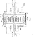
- FIG. 1 a system 1 according to the invention is schematically illustrated.
- the system shows an absorber 100, also referred to compact atmospheric rotating absorber (CARA) arranged to receive a gas stream 10 such as flue gas or exhaust gas and lean absorption liquid, also referred to as lean amine, to be used for the absorption process.
- a desorber 200 also referred to as rotating desorber wheel (RDW 2.0) arranged to receive absorption liquid 3 rich in CO 2 and pressurized steam 4 to be used as heating medium in the desorption process where C02 is desorbed from the CO 2 rich absorption liquid 3 which is regenerated and leaves the desorber as lean absorption liquid (2).
- the system is further provided with conventional equipment such as compressors, heat exchanger 5 , fans, pumps 6, storage tanks 7,14 , pipes, tubes and fittings and similar to complete the system for the accelerated process of absorption and desorption of CO 2 according to the invention.
- conventional equipment such as compressors, heat exchanger 5 , fans, pumps 6, storage tanks 7,14 , pipes, tubes and fittings and similar to complete the system for the accelerated process of absorption and desorption of CO 2 according to the invention.
- the system and process according to the invention allows for using a high amine concentration, up to 95 % by weight, and in particular approximately 50-70% by weight.
- the present invention is suitable to be used with absorption liquid comprising one of the following MEA, MDEA, DEA, or a mixture of different amines or other absorption liquids such as ionic liquid.
- Fig. 2 shows the absorber 100 which is provided with a stationary casing 101 having a longitudinal axis and a gas stream inlet 102 and outlet.
- a gas stream 10 containing CO 2 is supplied to the gas stream inlet of the absorber.
- the casing 101 encloses a rotatable main cylinder 104 which has an absorption section 105 , a demister section 106 and a washing section 107 arranged in series in direction of the gas flow.
- the mantle surface 108 of the main cylinder functions as the outer perimeter in the radial direction of each section.
- the absorption section 105 is provided with a plurality of spray means 109 arranged in the centre of the main cylinder.
- the spray means 109 are arranged to spray absorption liquid 14 into the gas stream 10 in the radial direction towards the perimeter of the main cylinder.
- the spray means and the perimeter of the main cylinder are means for disintegration 111 of the droplets provided to atomize the droplets and improve the turbulence inside the droplets thereby increasing the absorption efficiency. This is particularly important since the absorption liquid is very viscous and highly concentrated.
- the droplet disintegration means 111 are formed as a plurality of rotatable cylinders of permeable material, such as densely perforated plates, which are perforated all around the circumference and along the whole length of the cylinder.
- the perforations 114 are shown in Figure 3 .
- the main cylinder 104 and the perforated cylinders 111 are coaxial and are arranged to rotate about the common longitudinal axis by mechanical driving means 112 of conventional type provided in the absorber.
- the means for disintegration of droplets comprises 3-50 or more coaxial cylinder which are arranged between the spray means and the mantle surface of the main cylinder.
- the cylinders are arranged such that the gas stream passes in the axial direction in between the cylinders and is treated by the absorption liquid droplets which are moved in cross-flow direction to the gas stream by aid of the centrifugal effect caused by the rotation of the cylinders.
- the distance between the cylinders is adapted such that the droplets of absorption liquid (113) are well exposed to the passing gas stream in order to achieve good absorption without blocking or hindering the gas stream.
- the cylinders 111 are densely perforated such that the droplets pass through the perforations 114 by aid of centrifugal forces without forming a liquid layer on the inside surface of the perforated cylinder. Since the perforated cylinders rotate together with the main cylinder, the droplets are atomized and finely divided when passing through the perforations, thus very good mixing inside the droplets is achieved which improves the absorption of CO 2 .
- the finely atomised absorption liquid droplets provide that large surfaces for mass transfer purpose are exposed to the passing flue gas comprising CO 2 .
- the average droplet size of absorption liquid decreases with the distance from the centre and the volume of gas between the cylinders increases further out from the hollow axle which allows for high level of absorption of CO 2
- the absorption liquid collected at the perimeter of the main cylinder is thus rich in CO 2 .
- the perforated cylinders 111 are attached to the main cylinder 104 by conventional fastening means not shown in the figure but this may easily be done with use of appropriate stays, such that the main cylinder and the inner perforated cylinders rotate together about a common axis.
- the absorber 100 is further provided with a demister section 106 arranged in the main cylinder directly after the absorption section.
- the demister section collects and removes remaining droplets of absorption liquid 113 in the treated gas stream 10.
- the demister is provided with a packed bed material 115, which is arranged to rotate together with the main cylinder. The treated gas stream 10 flows through the packed bed material 115 and droplets of absorption liquid 113 are moved by centrifugal force to the perimeter of the main cylinder.
- the absorber 100 is further provided with a wash section 107 arranged in the main cylinder directly after the demister section 106.
- the wash section is arranged like the absorption section and has spray means 109 arranged in the centre for spraying wash liquid into the treated gas stream.
- the wash section is also provided with means for disintegration of droplets 111 comprising a plurality of rotatable perforated cylinders for atomizing the wash liquid droplets. The droplets are moved by aid of centrifugal force in a cross-flow direction through the gas stream and through the perforated cylinders such that the wash liquid droplets 119 absorb absorption liquid dissolved in the treated gas stream.
- demister section arranged after the wash section such that all wash liquid is removed from the cleaned gas before the gas vented to the atmosphere.
- the absorber 100 is operated at atmospheric pressure. Pressure drop is an important design parameter for atmospheric CO 2 capture. It is therefore preferred to install sufficient pressure generation (fans) at the gas inlet (not shown in the figures) have to overcome pressure drop throughout the absorber.
- Rich absorption liquid RA is collected at the perimeter of the main cylinder 104 and forms a liquid layer on the inside of the main cylinder surface.
- the main cylinder is provided with liquid outlets 116 , through holes in the mantle surface 104 where the collected liquid is discharged.
- the liquid outlets are distributed over the whole main cylinder surface such that both the absorption liquid and the wash liquid is collected and removed via the liquid outlets in respective sections.
- the liquid outlets 116 arranged on the surface of the main cylinder may optionally be provided with energy recovering means.
- the energy recovery means comprises diffusers 117 connected to the liquid outlets 116.
- the diffusers 117 are formed such that the kinetic energy in the liquid layer collected and formed on the inside of the main cylinder is converted into hydrodynamic energy.
- the diffusers 117 are formed like short tubes with a decreasing cross - section and are directed towards the casing 101 enclosing the main cylinder.
- the hydrodynamic energy is used as hydrodynamic driving force to rotate the cylinder. This is advantageous in that less power is used by the means for rotating the absorber.
- the system is further provided with a desorber 200 which is connected to the absorber 100 to receive CO 2 rich absorption liquid.
- the desorber 200 has a rotatable desorption cylinder 201 which is provided with a desorption chamber 202 and a steam chamber 203.
- the desorption cylinder 201 is also provided with an absorbent collection chamber 204 for collecting lean absorption liquid (2).
- the desorption cylinder is rotated by conventional drive means 205 arranged in a suitable manner.
- the desorption chamber 202 and the steam chamber 203 are integrated in the desorption cylinder 201 to achieve a compact desorber 200. Efficient desorption is achieved without mixing the fluids, thus there is no exchange of substances or mass transfer between the fluids present in the chambers.
- the chambers are completely separated such that the chambers can be operated with different operating pressures.
- the system 1 can thus be used with highly pressurized fluids of up to 10 Bar which is advantageous in that energy consumption for desorption is reduced . By using an increased pressure of the released CO 2 the energy consumption for compression in the system 1 is also reduced.
- the integrated design of the desorption cylinder 201 and the utilisation of centrifugal force created by rotation of the desorption cylinder to force the absorption liquid droplets through the gas stream results in that the desorber is more compact compared to a conventional column and reboiler design.
- the desorption chamber 202 is provided with spray means 206 in the core region 209 close to the axis of rotation for spraying CO 2 rich absorption liquid 3 into the chamber.
- the chamber is further provided with a stripper unit 207 arranged between the core region 209 of the chamber and the perimeter 216 of the desorption cylinder 201.
- the stripper unit 207 is formed as a rotatable tube bundle heat exchanger having a large number of tubes 208 which are attached to the desorption cylinder 201 and rotate together with the cylinder about a rotation axis.
- the steam chamber 203 is connected to the tubes 208 in the rotating tube bundle heat exchanger 207 such that heated steam 4 is supplied to the inside of the tubes from the steam chamber.
- the steam condenses in the tubes in the desorption process and the steam condensate 9 is returned via a steam condensate chamber 211 and steam condensate channels 224 (shown in the upper part of the desorption chamber illustrated in Fig. 4 ) to the steam chamber.
- the absorption liquid droplets 212 are sprayed into the core of the desorption chamber 202 and moved by aid of centrifugal force through the tube bundle heat exchanger 207.
- the desorption process takes place on the outside surface of the tubes 208 where absorption liquid droplets 212 are indirectly heated and releases CO 2 and vapours 13.
- the desorption cylinder 201 is also provided with an absorbent collection chamber 204 for collecting lean absorption liquid 2.
- the lean absorption liquid 2 moves to the periphery 216 of the desorption chamber.
- Absorbent channels 217 (shown in the lower part of the desorption chamber in Fig. 4 ) are provided on the perimeter 216 of the desorption chamber and connects the desorption chamber 202 to the absorbent collection chamber 204.
- the lean absorption liquid 2 is transferred via the absorbent channels 217 to the absorbent collection chamber where the lean absorbent forms a layer 218 on the perimeter of the rotating desorption cylinder.
- CO 2 and vapours 13 released in the desorption process flows towards the core region 209 of the desorption chamber and preheats the absorption liquid droplets moving outwards.
- CO 2 is removed from the desorption chamber via an outlet 220 arranged in the core region of the desorption chamber.
- the absorbent channels 217 and the condensate channels 224 are arranged all around the perimeter of the desorption cylinder.
- the desorber is provided with means for recovery of kinetic energy in the liquid layer formed on the inside surface of the desorption cylinder in the absorbent collecting chamber 204.
- the absorbent collection chamber 204 is provided with the diffuser means 221 to remove the lean absorbent from the chamber.
- the diffuser means are formed of a plurality of stationary diffuser arms, which are connected to a lean absorbent outlet conduit 222 arranged along the axis of rotation of the desorption cylinder.
- Each diffuser arm 221 is formed like a hollow pipe 223 provided with a liquid inlet arranged in near proximity of the outer perimeter of the absorbent collection chamber.
- the liquid inlet 228 is funnel shaped and has a cross-section which decreases in the flow direction of the absorbent.
- the kinetic energy in the rotating layer 218 of the lean absorption liquid 2 is recovered and converted into hydrodynamic energy such as a pressure head.
- the pressure head has a pumping effect and the liquid is pumped out from the absorbent collection chamber to a storage tank by aid of this pumping effect.
- the diffuser means By using the diffuser means, at least a part of the supplied energy in order to rotate the desorption cylinder is recovered. Also investments in separate pumps can be avoided.
- the steam chamber 203 is also provided with diffuser means 221 of the same type as in the absorbent collection chamber 204 for removing steam condensate 9 in the same manner from the desorber.
- the desorption cylinder 201 is designed such that conduits 230,231 for supplying CO 2 rich absorption liquid 3 and removal of lean absorption liquid 2 are provided in the core region along the axis of rotation of the desorption cylinder, and also the conduit 232 for removing steam condensate 9 from the desorber is provided along the axis of rotation of the desorption cylinder 201.
- This design decreases the size of the desorber 200 and provides efficient liquid supply and removal systems and demands less energy and investments in pumps and other equipment.
- the regeneration of the CO 2 rich absorption liquid 3 results in a stream of lean absorption liquid 2 and a gas stream 13 of CO 2 and vapour.
- the desorber 200 contributes to the steam consumption in the system by use of steam for heating of preheated rich amine to desorption exit temperature, heat for desorption of CO 2 and water vapor leaving the desorber together with CO 2 .
- Trials indicate that the steam consumption of the desorber amounts to a 30% reduction in steam consumption compared to conventional CO 2 capture process cwhich implies less water vapor leaving with the CO 2 .
- amine solution 70 wt% MEA in water. This will reduce steam consumption needed for CO 2 desorption by almost 30% compared to prior known processes using an amine solution of 30 wt% MEA in water amine.
- a system 1 according to the invention where the desorber 200 is operated at pressure of 3 bara reduces the compressor energy by almost 20% compared to a desorber of alternative type having operational pressure of 1.7 bara (no compressor steps avoided).
- the rotating desorber in the system according to the invention is operated at pressure of 5 bara the compressor energy is reduced by almost 30% compared to a desorber of different type having operational pressure of 1.7 bara.
- the absorption liquid 2, 3 is circulated in the system.
- the system provides for efficient circulation of the absorption liquid, water, CO 2 , and vapour.
- Heat exchangers and condensers of different types are used in various process steps for recovering heat and adjusting the operational parameters to achieve high energy efficiency of the system.
- Rich Amine from the absorber CARA is pumped via a storage tank to the desorber RDW 2.0.
- the rich amine flow which is fed to the desorber 200 is pre-heated by cooling warm desorbed lean amine 2 coming from the desorber 200, and then heated to desorber operating temperature by steam.
- the lean amine is further cooled by water to the desired temperature before it is pumped back to the lean amine storage tank 7 of the absorber
- Warm gases, water vapour and CO 2 , 13 from the gas outlet of the desorber are cooled and water separated in a gas/liquid separator. Energy can be recovered from this stream by condensing of water vapor. Released CO 2 is washed with water and is either sent to atmosphere or recycled to increase CO 2 concentration in the gas feed.
Description
- The present invention relates to a system and a process for absorption and desorption of CO2.
- A standard design of a plant used for carbon dioxide removal from a gas stream such as a flue gas or natural gas comprises a blower either before or after an indirect or direct contact cooler to boost the gas pressure, a separate boiler, followed by a cooler for the gas before the carbon dioxide is removed in an absorption column where the gas is contacted counter-currently to an absorbent flowing downwards. In the top of the column a wash section is fitted to remove, essentially with water, remnants of absorbent following the flue gas from the CO2 removal section.
- The known plants and processes for removing CO2 from a gas stream involve equipment that causes a significant pressure drop in the gas.
- Absorbent rich in CO2 from the lower part of the absorber column is pumped to the top of a desorption column via a heat recovery heat exchanger rendering the rich absorbent pre-heated before entering the desorption tower. The absorbent rich in CO2 is introduced at the top and is stripped by steam moving up the tower. Steam and absorption liquid following CO2 over the top is recovered in a condenser over the desorber top. Vapour is then formed in a reboiler from where the absorption liquid lean in CO2 is pumped via a heat recovery heat exchanger and a cooler to the top of the absorption column.
- Thus, conventional plants consists of very large units comprising a large number of process equipment and require instrumentation and control, in addition to a complex piping system to connect the various units.
- A further problem is that there is a lot of energy and heat exchange involved with circulating large amounts of diluted absorbent through the absorption-desorption process. The amount of solution that has to be circulated is highly influenced by the concentration of absorbent that is used in the process. The higher the concentration the less diluent has to be heated, cooled and circulated. The factors that influence the applicable concentration is the viscosity of the solution, the corrosiveness of the solution, the solubility as well as other chemical and physical properties of the solution and the equipment to be used.
- An object of at least the preferred embodiments of the present invention is to achieve a system and a process allowing the use of highly concentrated CO2 absorption liquid in the CO2 absorption and desorption process.
-
WO 2012/092981 A1 discloses background information. - The invention provides a system for accelerated absorption and desorption of CO2 as defined in claim 1, and a process for accelerated absorption and desorption of CO2 as defined in
claim 10. - By using centrifugal effect due to rotation both in the absorber and the desorber it is achieved that the system can handle very viscous solutions. The centrifugal effect improves the efficiency and in both the absorber and the desorber and allows the use of very viscous and highly concentrated absorption liquid. The system is therefore significantly more efficient, up to 30% higher efficiency than conventional plants using standard MEA solutions.
- Embodiments of the present invention utilize a high amine concentration, up to 95 % by weight, in particular an amine concentration of approximately 50-70% by weight, and the absorption liquid may have a viscosity of up to 1500 nPa·s.
- This has the further effect that the amounts of circulated absorption liquid is significantly lower, and also the absorption circulation rate is lower. Also the need for heating and cooling large amounts of 15 diluents is therefore reduced.
- Another advantage is that the retention times of solvents are short in both absorber and desorber and hence the oxidative and thermal degeneration of solvent is also reduced, thus the system and process provides an accelerated absorption and desorption of CO2 in comparison to previous known processes. Both the absorber and the desorber are very compact and fewer elements are necessary to carry out the absorption of CO2 and the regeneration of absorption liquid in the desorption process. Another advantage is that since the desorber is operated under pressure, the compressor investments is reduced in comparison to the conventional case. An operating pressure of 5 bara in the desorber gives that one CO2 compressor stage can be omitted in the plant. The footprint (equipment size) and the investment costs for the system according to the invention is therefore significantly reduced in comparison to previously known plants.
- Furthermore, the energy consumption for compression compared to standard capture processes (depending on the operational pressure in the desorber) amounts to almost 20% reduced energy consumption for an operational pressure of 3 bara, and an energy consumption reduced by almost 30% for an operation pressure of 5 bara in comparison to a design case where the operational pressure is 1.7 bara.
- Other distinctive features and advantages with the invention will be evident in the dependent claims and the following detailed description of preferred embodiments of the invention.
-
Figure 1 schematically illustrates a system according to the invention. -
Figure 2 schematically illustrates the absorber in detail. -
Figure 3 schematically shows details of the absorber. -
Figure 4 schematically illustrates the desorber in detail. - It should be noted that the figures only show details which are important for the understanding of the invention. Moreover, same features are indicated by the same reference number throughout the specification. It should also be noted that the illustrated apparatus and the features thereof are out of proportion in relation to each other and the indicated features and dimensions thereof are exaggerated. The features are shown in this manner for explanatory purposes only.
- With reference to
figure 1 a system 1 according to the invention is schematically illustrated. - The system shows an
absorber 100, also referred to compact atmospheric rotating absorber (CARA) arranged to receive agas stream 10 such as flue gas or exhaust gas and lean absorption liquid, also referred to as lean amine, to be used for the absorption process. Adesorber 200 , also referred to as rotating desorber wheel (RDW 2.0) arranged to receiveabsorption liquid 3 rich in CO2 and pressurizedsteam 4 to be used as heating medium in the desorption process where C02 is desorbed from the CO2rich absorption liquid 3 which is regenerated and leaves the desorber as lean absorption liquid (2). The system is further provided with conventional equipment such as compressors, heat exchanger 5 , fans, pumps 6,storage tanks 7,14 , pipes, tubes and fittings and similar to complete the system for the accelerated process of absorption and desorption of CO2 according to the invention. These types of equipments are previously known and therefore not further described here. - The system and process according to the invention allows for using a high amine concentration, up to 95 % by weight, and in particular approximately 50-70% by weight.
- The present invention is suitable to be used with absorption liquid comprising one of the following MEA, MDEA, DEA, or a mixture of different amines or other absorption liquids such as ionic liquid.
-
Fig. 2 shows theabsorber 100 which is provided with astationary casing 101 having a longitudinal axis and agas stream inlet 102 and outlet. Agas stream 10 containing CO2 is supplied to the gas stream inlet of the absorber. - The
casing 101 encloses a rotatablemain cylinder 104 which has anabsorption section 105 , ademister section 106 and awashing section 107 arranged in series in direction of the gas flow. Themantle surface 108 of the main cylinder functions as the outer perimeter in the radial direction of each section. Theabsorption section 105 is provided with a plurality of spray means 109 arranged in the centre of the main cylinder. The spray means 109 are arranged to sprayabsorption liquid 14 into thegas stream 10 in the radial direction towards the perimeter of the main cylinder. Between the spray means and the perimeter of the main cylinder are means fordisintegration 111 of the droplets provided to atomize the droplets and improve the turbulence inside the droplets thereby increasing the absorption efficiency. This is particularly important since the absorption liquid is very viscous and highly concentrated. - The droplet disintegration means 111 are formed as a plurality of rotatable cylinders of permeable material, such as densely perforated plates, which are perforated all around the circumference and along the whole length of the cylinder. The
perforations 114 are shown inFigure 3 . - The
main cylinder 104 and theperforated cylinders 111 are coaxial and are arranged to rotate about the common longitudinal axis by mechanical driving means 112 of conventional type provided in the absorber. The means for disintegration of droplets comprises 3-50 or more coaxial cylinder which are arranged between the spray means and the mantle surface of the main cylinder. The cylinders are arranged such that the gas stream passes in the axial direction in between the cylinders and is treated by the absorption liquid droplets which are moved in cross-flow direction to the gas stream by aid of the centrifugal effect caused by the rotation of the cylinders. The distance between the cylinders is adapted such that the droplets of absorption liquid (113) are well exposed to the passing gas stream in order to achieve good absorption without blocking or hindering the gas stream. - The
cylinders 111 are densely perforated such that the droplets pass through theperforations 114 by aid of centrifugal forces without forming a liquid layer on the inside surface of the perforated cylinder. Since the perforated cylinders rotate together with the main cylinder, the droplets are atomized and finely divided when passing through the perforations, thus very good mixing inside the droplets is achieved which improves the absorption of CO2. The finely atomised absorption liquid droplets provide that large surfaces for mass transfer purpose are exposed to the passing flue gas comprising CO2. - The average droplet size of absorption liquid decreases with the distance from the centre and the volume of gas between the cylinders increases further out from the hollow axle which allows for high level of absorption of CO2 The absorption liquid collected at the perimeter of the main cylinder is thus rich in CO2.
- The
perforated cylinders 111 are attached to themain cylinder 104 by conventional fastening means not shown in the figure but this may easily be done with use of appropriate stays, such that the main cylinder and the inner perforated cylinders rotate together about a common axis. - The
absorber 100 is further provided with ademister section 106 arranged in the main cylinder directly after the absorption section. The demister section collects and removes remaining droplets of absorption liquid 113 in the treatedgas stream 10. The demister is provided with a packedbed material 115, which is arranged to rotate together with the main cylinder. The treatedgas stream 10 flows through the packedbed material 115 and droplets of absorption liquid 113 are moved by centrifugal force to the perimeter of the main cylinder. - The
absorber 100 is further provided with awash section 107 arranged in the main cylinder directly after thedemister section 106. The wash section is arranged like the absorption section and has spray means 109 arranged in the centre for spraying wash liquid into the treated gas stream. The wash section is also provided with means for disintegration ofdroplets 111 comprising a plurality of rotatable perforated cylinders for atomizing the wash liquid droplets. The droplets are moved by aid of centrifugal force in a cross-flow direction through the gas stream and through the perforated cylinders such that the wash liquid droplets 119 absorb absorption liquid dissolved in the treated gas stream. - Optionally, there is also a further demister section arranged after the wash section such that all wash liquid is removed from the cleaned gas before the gas vented to the atmosphere.
- The
absorber 100 is operated at atmospheric pressure. Pressure drop is an important design parameter for atmospheric CO2 capture. It is therefore preferred to install sufficient pressure generation (fans) at the gas inlet (not shown in the figures) have to overcome pressure drop throughout the absorber. - Rich absorption liquid RA, is collected at the perimeter of the
main cylinder 104 and forms a liquid layer on the inside of the main cylinder surface. The main cylinder is provided withliquid outlets 116 , through holes in themantle surface 104 where the collected liquid is discharged. The liquid outlets are distributed over the whole main cylinder surface such that both the absorption liquid and the wash liquid is collected and removed via the liquid outlets in respective sections. - The
liquid outlets 116 arranged on the surface of the main cylinder may optionally be provided with energy recovering means. The energy recovery means comprises diffusers 117 connected to theliquid outlets 116. The diffusers 117 are formed such that the kinetic energy in the liquid layer collected and formed on the inside of the main cylinder is converted into hydrodynamic energy. The diffusers 117 are formed like short tubes with a decreasing cross - section and are directed towards thecasing 101 enclosing the main cylinder. The hydrodynamic energy is used as hydrodynamic driving force to rotate the cylinder. This is advantageous in that less power is used by the means for rotating the absorber. - The system is further provided with a
desorber 200 which is connected to theabsorber 100 to receive CO2 rich absorption liquid. Thedesorber 200 has arotatable desorption cylinder 201 which is provided with adesorption chamber 202 and asteam chamber 203. Thedesorption cylinder 201 is also provided with anabsorbent collection chamber 204 for collecting lean absorption liquid (2). The desorption cylinder is rotated by conventional drive means 205 arranged in a suitable manner. - The
desorption chamber 202 and thesteam chamber 203 are integrated in thedesorption cylinder 201 to achieve acompact desorber 200. Efficient desorption is achieved without mixing the fluids, thus there is no exchange of substances or mass transfer between the fluids present in the chambers. The chambers are completely separated such that the chambers can be operated with different operating pressures. The system 1 can thus be used with highly pressurized fluids of up to 10 Bar which is advantageous in that energy consumption for desorption is reduced . By using an increased pressure of the released CO2 the energy consumption for compression in the system 1 is also reduced. - The integrated design of the
desorption cylinder 201 and the utilisation of centrifugal force created by rotation of the desorption cylinder to force the absorption liquid droplets through the gas stream results in that the desorber is more compact compared to a conventional column and reboiler design. - The
desorption chamber 202 is provided with spray means 206 in the core region 209 close to the axis of rotation for spraying CO2rich absorption liquid 3 into the chamber. The chamber is further provided with astripper unit 207 arranged between the core region 209 of the chamber and theperimeter 216 of thedesorption cylinder 201. - The
stripper unit 207 is formed as a rotatable tube bundle heat exchanger having a large number oftubes 208 which are attached to thedesorption cylinder 201 and rotate together with the cylinder about a rotation axis. - The
steam chamber 203 is connected to thetubes 208 in the rotating tubebundle heat exchanger 207 such thatheated steam 4 is supplied to the inside of the tubes from the steam chamber. The steam condenses in the tubes in the desorption process and thesteam condensate 9 is returned via a steam condensate chamber 211 and steam condensate channels 224 (shown in the upper part of the desorption chamber illustrated inFig. 4 ) to the steam chamber. - The absorption liquid droplets 212 are sprayed into the core of the
desorption chamber 202 and moved by aid of centrifugal force through the tubebundle heat exchanger 207. The desorption process takes place on the outside surface of thetubes 208 where absorption liquid droplets 212 are indirectly heated and releases CO2 and vapours 13. Thedesorption cylinder 201 is also provided with anabsorbent collection chamber 204 for collectinglean absorption liquid 2. Thelean absorption liquid 2 moves to theperiphery 216 of the desorption chamber. Absorbent channels 217 (shown in the lower part of the desorption chamber inFig. 4 ) are provided on theperimeter 216 of the desorption chamber and connects thedesorption chamber 202 to theabsorbent collection chamber 204. Thelean absorption liquid 2 is transferred via theabsorbent channels 217 to the absorbent collection chamber where the lean absorbent forms alayer 218 on the perimeter of the rotating desorption cylinder. CO2 and vapours 13 released in the desorption process flows towards the core region 209 of the desorption chamber and preheats the absorption liquid droplets moving outwards. CO2 is removed from the desorption chamber via anoutlet 220 arranged in the core region of the desorption chamber. - The
absorbent channels 217 and thecondensate channels 224 are arranged all around the perimeter of the desorption cylinder. - The desorber is provided with means for recovery of kinetic energy in the liquid layer formed on the inside surface of the desorption cylinder in the
absorbent collecting chamber 204. Theabsorbent collection chamber 204 is provided with the diffuser means 221 to remove the lean absorbent from the chamber. The diffuser means are formed of a plurality of stationary diffuser arms, which are connected to a leanabsorbent outlet conduit 222 arranged along the axis of rotation of the desorption cylinder. Eachdiffuser arm 221 is formed like a hollow pipe 223 provided with a liquid inlet arranged in near proximity of the outer perimeter of the absorbent collection chamber. Theliquid inlet 228 is funnel shaped and has a cross-section which decreases in the flow direction of the absorbent. The kinetic energy in therotating layer 218 of thelean absorption liquid 2 is recovered and converted into hydrodynamic energy such as a pressure head. The pressure head has a pumping effect and the liquid is pumped out from the absorbent collection chamber to a storage tank by aid of this pumping effect. By using the diffuser means, at least a part of the supplied energy in order to rotate the desorption cylinder is recovered. Also investments in separate pumps can be avoided. - The
steam chamber 203 is also provided with diffuser means 221 of the same type as in theabsorbent collection chamber 204 for removingsteam condensate 9 in the same manner from the desorber. - The
desorption cylinder 201 is designed such that conduits 230,231 for supplying CO2rich absorption liquid 3 and removal oflean absorption liquid 2 are provided in the core region along the axis of rotation of the desorption cylinder, and also the conduit 232 for removingsteam condensate 9 from the desorber is provided along the axis of rotation of thedesorption cylinder 201. This design decreases the size of thedesorber 200 and provides efficient liquid supply and removal systems and demands less energy and investments in pumps and other equipment. The regeneration of the CO2rich absorption liquid 3 results in a stream oflean absorption liquid 2 and agas stream 13 of CO2 and vapour. - The
desorber 200 contributes to the steam consumption in the system by use of steam for heating of preheated rich amine to desorption exit temperature, heat for desorption of CO2 and water vapor leaving the desorber together with CO2. Trials indicate that the steam consumption of the desorber amounts to a 30% reduction in steam consumption compared to conventional CO2 capture process cwhich implies less water vapor leaving with the CO2. It should be noted that there is significantly reduced energy consumption for amine desorption due to compact equipment design and the use of highly concentrated absorption liquid, amine solution (70 wt% MEA in water). This will reduce steam consumption needed for CO2 desorption by almost 30% compared to prior known processes using an amine solution of 30 wt% MEA in water amine. - Furthermore it should be noted that the operational pressure of the rotating desorber in the system can be significantly higher than for known desorption alternatives, due to the design of the system and the design of the desorber. Hence CO2 compressor energy consumption post the desorption process and the subsequent pressurisation to the required level of 70 bar is less than for alternative strippers.
- Furthermore, a system 1 according to the invention where the
desorber 200 is operated at pressure of 3 bara reduces the compressor energy by almost 20% compared to a desorber of alternative type having operational pressure of 1.7 bara (no compressor steps avoided). In case the rotating desorber in the system according to the invention is operated at pressure of 5 bara the compressor energy is reduced by almost 30% compared to a desorber of different type having operational pressure of 1.7 bara. - The
absorption liquid desorber 200 is pre-heated by cooling warm desorbedlean amine 2 coming from thedesorber 200, and then heated to desorber operating temperature by steam. The lean amine is further cooled by water to the desired temperature before it is pumped back to the lean amine storage tank 7 of the absorber
Warm gases, water vapour and CO2, 13 from the gas outlet of the desorber are cooled and water separated in a gas/liquid separator. Energy can be recovered from this stream by condensing of water vapor. Released CO2 is washed with water and is either sent to atmosphere or recycled to increase CO2 concentration in the gas feed.
Claims (10)
- A system for accelerated absorption and desorption of CO2 comprising an absorber (100) for absorbing CO2 from a gas stream (10) by use of absorption liquid and a desorber (200) for desorbing CO2 from CO2 rich absorption liquid, characterized in that
the absorber (100) comprises a rotatable main cylinder (104) having an absorption section (105) provided with rotatable means for disintegration of droplets (111) of absorption liquid and means for rotating (112) the absorber, such that absorption liquid droplets (113) are moved by aid of centrifugal force in a cross flow-direction in relation to the gas stream (10), so that the direction of the flow of absorption liquid droplets (113) is substantially orthogonal to the direction of the flow of the gas stream (10), and being atomized by the means for disintegration of droplets whereby CO2 is absorbed from the gas stream by the absorption liquid droplets,
the desorber (200) is connected to the absorber to receive CO2 rich absorption liquid,
the desorber (200) is rotatable and comprises a desorption chamber (202) provided with a rotatable heat exchanger (207) and means for rotating (205) the desorber, such that the absorption liquid droplets (212) are moved by aid of centrifugal force through the heat exchanger (207) whereby the absorption liquid droplets are heated and CO2 is desorbed and separated from the absorption liquid droplets, and lean absorption liquid (2) is circulated to the absorber (100). - A system according to claim 1, wherein the means for disintegration of droplets (111) comprises a plurality of perforated rotating cylinders.
- A system according to any preceding claim, wherein the desorber is provided with means for recovery of kinetic energy (221) in the lean absorption liquid (2) and/or steam condensate (9);
wherein the desorber is provided with stationary diffusers (221) arranged in an absorbent collection chamber (204) adapted to convert kinetic energy in the lean absorption liquid (2) into hydrodynamic energy; and/or
wherein the desorber is provided with stationary diffusers (221) arranged in a steam chamber (203) to convert kinetic energy in steam condensate (9) into hydrodynamic energy. - A system according to any preceding claim, wherein the main cylinder of the absorber has a demister section (106) arranged after the absorption section (105) which is adapted to remove droplets of absorption liquid (113) from the treated gas stream.
- A system according to any preceding claim, wherein the main cylinder (104) of the absorber has a wash section (107) arranged after the demister section where wash liquid is sprayed into the gas stream, and provided with means for disintegration of droplets (111), and the wash liquid droplets (119) are moved by aid of centrifugal force in a cross-flow direction in relation to the gas stream, so that the direction of the flow of wash liquid droplets (119) is substantially orthogonal to the direction of the flow of the gas stream, whereby the wash liquid droplets absorb absorption liquid dissolved in the treated gas stream.
- A system according to claim 5, wherein the main cylinder (104) of the absorber is provided with a demister section which is arranged after the wash section (107), and the demister section is adapted for removing droplets of wash liquid from the treated gas stream.
- A system according to any preceding claim, wherein the desorber (200) comprises a steam chamber (203), and that the desorption chamber (202) and the steam chamber (203) are arranged such that absorption liquid (2,3) in the desorption chamber (202) and heating medium (4,9) in the steam chamber are not mixed in the desorber.
- A system according to any preceding claim, the system being adapted to supply and remove absorption liquid (2,3) from the desorber along the axis of rotation of the desorption cylinder.
- A system according to any the previous claims adapted to remove steam condensate (9) from the desorber along the axis of rotation of the desorption cylinder.
- A process for accelerated absorption and desorption of CO2 comprising the steps of:- supplying a gas stream (10) containing CO2 to an absorber (100) having a rotating main cylinder (104),- spraying lean absorption liquid into the gas stream,- moving absorption liquid droplets (113, 212) in a cross-flow direction to the gas stream by aid of centrifugal force so that the direction of the flow of absorption liquid droplets (113, 212) is substantially orthogonal to the direction of the flow of the gas stream,- atomizing the droplets of absorption liquid (113) by means for disintegration of droplets (111),- absorbing CO2 from the gas stream (10) by absorption liquid droplets (113),- circulating CO2 rich absorption liquid (3) from the absorber to a rotating desorber (200) having a desorption chamber (202) provided with a rotating heat exchanger (207),- spraying CO2 rich absorption liquid in the desorption chamber (202),- supplying steam (4) to the heat exchanger,- moving droplets of absorption liquid (212) through heat exchanger (207) by aid of centrifugal force,- desorbing CO2 from absorption liquid,- separating CO2 from lean absorption liquid,- circulating lean absorption liquid (2) from the desorber (200) to the absorber (100).
Applications Claiming Priority (1)
| Application Number | Priority Date | Filing Date | Title |
|---|---|---|---|
| PCT/NO2013/050178 WO2015060723A1 (en) | 2013-10-22 | 2013-10-22 | System and process for absorption and desorption of co2 |
Publications (3)
| Publication Number | Publication Date |
|---|---|
| EP3068510A1 EP3068510A1 (en) | 2016-09-21 |
| EP3068510A4 EP3068510A4 (en) | 2017-05-24 |
| EP3068510B1 true EP3068510B1 (en) | 2019-09-11 |
Family
ID=52993212
Family Applications (1)
| Application Number | Title | Priority Date | Filing Date |
|---|---|---|---|
| EP13895964.8A Active EP3068510B1 (en) | 2013-10-22 | 2013-10-22 | System and process for absorption and desorption of co2 |
Country Status (2)
| Country | Link |
|---|---|
| EP (1) | EP3068510B1 (en) |
| WO (1) | WO2015060723A1 (en) |
Cited By (1)
| Publication number | Priority date | Publication date | Assignee | Title |
|---|---|---|---|---|
| WO2024046597A1 (en) * | 2022-08-30 | 2024-03-07 | Nuovo Pignone Tecnologie - S.R.L. | Spiral mesh rotating bed absorber for compact carbon capture |
Families Citing this family (2)
| Publication number | Priority date | Publication date | Assignee | Title |
|---|---|---|---|---|
| CN114632402B (en) * | 2020-12-16 | 2022-11-11 | 中冶京诚工程技术有限公司 | Trapping method of flue gas carbon dioxide trapping system |
| CN116492816B (en) * | 2023-03-23 | 2024-03-12 | 中国能源建设集团广东省电力设计研究院有限公司 | High CO 2 Loaded absorbent carbon capture desorption system and method |
Family Cites Families (6)
| Publication number | Priority date | Publication date | Assignee | Title |
|---|---|---|---|---|
| US2176982A (en) * | 1937-08-06 | 1939-10-24 | Sinclair Refining Co | Centrifugal countercurrent contacting machine |
| GB8300096D0 (en) * | 1982-01-19 | 1983-02-09 | Ici Plc | Removal of hydrogen sulphide from gas streams |
| US7252703B2 (en) * | 2003-06-30 | 2007-08-07 | Honeywell International, Inc. | Direct contact liquid air contaminant control system |
| US20110131937A1 (en) * | 2009-12-08 | 2011-06-09 | Yang Hsien Ming | absorptive device to carbon dioxide in the air |
| NO333941B1 (en) * | 2010-12-09 | 2013-10-28 | Statoil Petroleum As | PROCEDURE AND ABSORBES FOR REMOVAL OF ACID GAS FROM NATURAL GAS |
| WO2012092981A1 (en) * | 2011-01-07 | 2012-07-12 | Statoil Petroleum As | Method and absorber for removal of a contaminant from natural gas |
-
2013
- 2013-10-22 WO PCT/NO2013/050178 patent/WO2015060723A1/en active Application Filing
- 2013-10-22 EP EP13895964.8A patent/EP3068510B1/en active Active
Non-Patent Citations (1)
| Title |
|---|
| None * |
Cited By (1)
| Publication number | Priority date | Publication date | Assignee | Title |
|---|---|---|---|---|
| WO2024046597A1 (en) * | 2022-08-30 | 2024-03-07 | Nuovo Pignone Tecnologie - S.R.L. | Spiral mesh rotating bed absorber for compact carbon capture |
Also Published As
| Publication number | Publication date |
|---|---|
| EP3068510A4 (en) | 2017-05-24 |
| WO2015060723A1 (en) | 2015-04-30 |
| EP3068510A1 (en) | 2016-09-21 |
Similar Documents
| Publication | Publication Date | Title |
|---|---|---|
| US10155194B2 (en) | Method and apparatus for collecting carbon dioxide from flue gas | |
| US9381463B2 (en) | Method and absorber for removal of acid gas from natural gas | |
| JP5465246B2 (en) | Method and apparatus for separating carbon dioxide from exhaust gas from fossil fuel power plant equipment | |
| CN101423214A (en) | Method for catching carbon dioxide in generating plant flue gas by ammonia process and equipment thereof | |
| EP3068510B1 (en) | System and process for absorption and desorption of co2 | |
| JPWO2018190104A1 (en) | Apparatus and method for recovering carbon dioxide in flue gas | |
| CN113374552A (en) | Device system and method for capturing carbon dioxide by amine method and utilizing energy of analytical tower | |
| CN104107616A (en) | NMP (N-Methyl Pyrrolidone) gas treating equipment and treating process thereof | |
| CN114206472B (en) | Method and treatment device for treating gas by adsorption using thermally optimized thermal flash solvent regeneration | |
| WO2012092981A1 (en) | Method and absorber for removal of a contaminant from natural gas | |
| US20120174782A1 (en) | Compact absorption-desorption process and apparatus using concentrated solution | |
| CN215486191U (en) | Device system for capturing energy of carbon dioxide analysis tower by amine method | |
| CN112391216A (en) | Device and method for regenerating triethylene glycol solvent | |
| JPH06315613A (en) | Recovering apparatus for solvent | |
| CN210057794U (en) | Equipment for reducing temperature and water content of wet flue gas in wet washing | |
| CA2909907C (en) | System and method for desorption of acid gas from an absorption liquid | |
| CN210584416U (en) | Exhaust gas treatment device | |
| EP3068509B1 (en) | Apparatus and method for absorbing co2 from flue gas | |
| WO2015060725A1 (en) | Apparatus and method for absorbing co2 from natural gas | |
| CN108905522A (en) | A kind of alcohol ethers and aromatic solvent VOCs treatment system and method | |
| CN215982493U (en) | Energy recovery device system of amine method carbon dioxide capture coupling coal-fired boiler | |
| US9702269B2 (en) | Device for capture of acid gas contained in combustion fumes | |
| CN116272315A (en) | Micro-interface oscillation absorber, regenerator, carbon capture and regeneration system and method | |
| CN109999603A (en) | A kind of device and method reducing wet scrubbing wet flue gas temperature and water content |
Legal Events
| Date | Code | Title | Description |
|---|---|---|---|
| PUAI | Public reference made under article 153(3) epc to a published international application that has entered the european phase |
Free format text: ORIGINAL CODE: 0009012 |
|
| 17P | Request for examination filed |
Effective date: 20160426 |
|
| AK | Designated contracting states |
Kind code of ref document: A1 Designated state(s): AL AT BE BG CH CY CZ DE DK EE ES FI FR GB GR HR HU IE IS IT LI LT LU LV MC MK MT NL NO PL PT RO RS SE SI SK SM TR |
|
| AX | Request for extension of the european patent |
Extension state: BA ME |
|
| DAX | Request for extension of the european patent (deleted) | ||
| A4 | Supplementary search report drawn up and despatched |
Effective date: 20170424 |
|
| RIC1 | Information provided on ipc code assigned before grant |
Ipc: B01D 53/48 20060101ALI20170418BHEP Ipc: B01D 3/08 20060101AFI20170418BHEP Ipc: B01D 53/14 20060101ALI20170418BHEP Ipc: B01D 53/18 20060101ALI20170418BHEP Ipc: B01D 53/78 20060101ALI20170418BHEP Ipc: B01D 53/96 20060101ALI20170418BHEP Ipc: B01D 53/52 20060101ALI20170418BHEP Ipc: B01D 53/40 20060101ALI20170418BHEP Ipc: B01D 53/62 20060101ALI20170418BHEP |
|
| STAA | Information on the status of an ep patent application or granted ep patent |
Free format text: STATUS: EXAMINATION IS IN PROGRESS |
|
| RAP1 | Party data changed (applicant data changed or rights of an application transferred) |
Owner name: ADVANCED MASS TRANSFER TECHNOLOGY AS |
|
| 17Q | First examination report despatched |
Effective date: 20180322 |
|
| RAP1 | Party data changed (applicant data changed or rights of an application transferred) |
Owner name: FJELL BIODRY AS |
|
| GRAP | Despatch of communication of intention to grant a patent |
Free format text: ORIGINAL CODE: EPIDOSNIGR1 |
|
| STAA | Information on the status of an ep patent application or granted ep patent |
Free format text: STATUS: GRANT OF PATENT IS INTENDED |
|
| INTG | Intention to grant announced |
Effective date: 20190319 |
|
| RAP1 | Party data changed (applicant data changed or rights of an application transferred) |
Owner name: COMPACT CARBON CAPTURE AS |
|
| GRAS | Grant fee paid |
Free format text: ORIGINAL CODE: EPIDOSNIGR3 |
|
| GRAA | (expected) grant |
Free format text: ORIGINAL CODE: 0009210 |
|
| STAA | Information on the status of an ep patent application or granted ep patent |
Free format text: STATUS: THE PATENT HAS BEEN GRANTED |
|
| AK | Designated contracting states |
Kind code of ref document: B1 Designated state(s): AL AT BE BG CH CY CZ DE DK EE ES FI FR GB GR HR HU IE IS IT LI LT LU LV MC MK MT NL NO PL PT RO RS SE SI SK SM TR |
|
| REG | Reference to a national code |
Ref country code: GB Ref legal event code: FG4D |
|
| REG | Reference to a national code |
Ref country code: CH Ref legal event code: EP |
|
| REG | Reference to a national code |
Ref country code: AT Ref legal event code: REF Ref document number: 1177715 Country of ref document: AT Kind code of ref document: T Effective date: 20190915 |
|
| REG | Reference to a national code |
Ref country code: DE Ref legal event code: R096 Ref document number: 602013060547 Country of ref document: DE Ref country code: IE Ref legal event code: FG4D |
|
| REG | Reference to a national code |
Ref country code: NL Ref legal event code: MP Effective date: 20190911 |
|
| REG | Reference to a national code |
Ref country code: LT Ref legal event code: MG4D Ref country code: NO Ref legal event code: T2 Effective date: 20190911 |
|
| PG25 | Lapsed in a contracting state [announced via postgrant information from national office to epo] |
Ref country code: HR Free format text: LAPSE BECAUSE OF FAILURE TO SUBMIT A TRANSLATION OF THE DESCRIPTION OR TO PAY THE FEE WITHIN THE PRESCRIBED TIME-LIMIT Effective date: 20190911 Ref country code: SE Free format text: LAPSE BECAUSE OF FAILURE TO SUBMIT A TRANSLATION OF THE DESCRIPTION OR TO PAY THE FEE WITHIN THE PRESCRIBED TIME-LIMIT Effective date: 20190911 Ref country code: FI Free format text: LAPSE BECAUSE OF FAILURE TO SUBMIT A TRANSLATION OF THE DESCRIPTION OR TO PAY THE FEE WITHIN THE PRESCRIBED TIME-LIMIT Effective date: 20190911 Ref country code: LT Free format text: LAPSE BECAUSE OF FAILURE TO SUBMIT A TRANSLATION OF THE DESCRIPTION OR TO PAY THE FEE WITHIN THE PRESCRIBED TIME-LIMIT Effective date: 20190911 Ref country code: BG Free format text: LAPSE BECAUSE OF FAILURE TO SUBMIT A TRANSLATION OF THE DESCRIPTION OR TO PAY THE FEE WITHIN THE PRESCRIBED TIME-LIMIT Effective date: 20191211 |
|
| PG25 | Lapsed in a contracting state [announced via postgrant information from national office to epo] |
Ref country code: GR Free format text: LAPSE BECAUSE OF FAILURE TO SUBMIT A TRANSLATION OF THE DESCRIPTION OR TO PAY THE FEE WITHIN THE PRESCRIBED TIME-LIMIT Effective date: 20191212 Ref country code: LV Free format text: LAPSE BECAUSE OF FAILURE TO SUBMIT A TRANSLATION OF THE DESCRIPTION OR TO PAY THE FEE WITHIN THE PRESCRIBED TIME-LIMIT Effective date: 20190911 Ref country code: ES Free format text: LAPSE BECAUSE OF FAILURE TO SUBMIT A TRANSLATION OF THE DESCRIPTION OR TO PAY THE FEE WITHIN THE PRESCRIBED TIME-LIMIT Effective date: 20190911 Ref country code: AL Free format text: LAPSE BECAUSE OF FAILURE TO SUBMIT A TRANSLATION OF THE DESCRIPTION OR TO PAY THE FEE WITHIN THE PRESCRIBED TIME-LIMIT Effective date: 20190911 Ref country code: RS Free format text: LAPSE BECAUSE OF FAILURE TO SUBMIT A TRANSLATION OF THE DESCRIPTION OR TO PAY THE FEE WITHIN THE PRESCRIBED TIME-LIMIT Effective date: 20190911 |
|
| REG | Reference to a national code |
Ref country code: AT Ref legal event code: MK05 Ref document number: 1177715 Country of ref document: AT Kind code of ref document: T Effective date: 20190911 |
|
| PG25 | Lapsed in a contracting state [announced via postgrant information from national office to epo] |
Ref country code: NL Free format text: LAPSE BECAUSE OF FAILURE TO SUBMIT A TRANSLATION OF THE DESCRIPTION OR TO PAY THE FEE WITHIN THE PRESCRIBED TIME-LIMIT Effective date: 20190911 Ref country code: RO Free format text: LAPSE BECAUSE OF FAILURE TO SUBMIT A TRANSLATION OF THE DESCRIPTION OR TO PAY THE FEE WITHIN THE PRESCRIBED TIME-LIMIT Effective date: 20190911 Ref country code: PL Free format text: LAPSE BECAUSE OF FAILURE TO SUBMIT A TRANSLATION OF THE DESCRIPTION OR TO PAY THE FEE WITHIN THE PRESCRIBED TIME-LIMIT Effective date: 20190911 Ref country code: PT Free format text: LAPSE BECAUSE OF FAILURE TO SUBMIT A TRANSLATION OF THE DESCRIPTION OR TO PAY THE FEE WITHIN THE PRESCRIBED TIME-LIMIT Effective date: 20200113 Ref country code: EE Free format text: LAPSE BECAUSE OF FAILURE TO SUBMIT A TRANSLATION OF THE DESCRIPTION OR TO PAY THE FEE WITHIN THE PRESCRIBED TIME-LIMIT Effective date: 20190911 Ref country code: IT Free format text: LAPSE BECAUSE OF FAILURE TO SUBMIT A TRANSLATION OF THE DESCRIPTION OR TO PAY THE FEE WITHIN THE PRESCRIBED TIME-LIMIT Effective date: 20190911 Ref country code: AT Free format text: LAPSE BECAUSE OF FAILURE TO SUBMIT A TRANSLATION OF THE DESCRIPTION OR TO PAY THE FEE WITHIN THE PRESCRIBED TIME-LIMIT Effective date: 20190911 |
|
| PG25 | Lapsed in a contracting state [announced via postgrant information from national office to epo] |
Ref country code: SM Free format text: LAPSE BECAUSE OF FAILURE TO SUBMIT A TRANSLATION OF THE DESCRIPTION OR TO PAY THE FEE WITHIN THE PRESCRIBED TIME-LIMIT Effective date: 20190911 Ref country code: SK Free format text: LAPSE BECAUSE OF FAILURE TO SUBMIT A TRANSLATION OF THE DESCRIPTION OR TO PAY THE FEE WITHIN THE PRESCRIBED TIME-LIMIT Effective date: 20190911 Ref country code: CZ Free format text: LAPSE BECAUSE OF FAILURE TO SUBMIT A TRANSLATION OF THE DESCRIPTION OR TO PAY THE FEE WITHIN THE PRESCRIBED TIME-LIMIT Effective date: 20190911 Ref country code: IS Free format text: LAPSE BECAUSE OF FAILURE TO SUBMIT A TRANSLATION OF THE DESCRIPTION OR TO PAY THE FEE WITHIN THE PRESCRIBED TIME-LIMIT Effective date: 20200224 |
|
| REG | Reference to a national code |
Ref country code: CH Ref legal event code: PL |
|
| REG | Reference to a national code |
Ref country code: DE Ref legal event code: R097 Ref document number: 602013060547 Country of ref document: DE |
|
| PLBE | No opposition filed within time limit |
Free format text: ORIGINAL CODE: 0009261 |
|
| STAA | Information on the status of an ep patent application or granted ep patent |
Free format text: STATUS: NO OPPOSITION FILED WITHIN TIME LIMIT |
|
| PG2D | Information on lapse in contracting state deleted |
Ref country code: IS |
|
| PG25 | Lapsed in a contracting state [announced via postgrant information from national office to epo] |
Ref country code: DK Free format text: LAPSE BECAUSE OF FAILURE TO SUBMIT A TRANSLATION OF THE DESCRIPTION OR TO PAY THE FEE WITHIN THE PRESCRIBED TIME-LIMIT Effective date: 20190911 Ref country code: LU Free format text: LAPSE BECAUSE OF NON-PAYMENT OF DUE FEES Effective date: 20191022 Ref country code: LI Free format text: LAPSE BECAUSE OF NON-PAYMENT OF DUE FEES Effective date: 20191031 Ref country code: CH Free format text: LAPSE BECAUSE OF NON-PAYMENT OF DUE FEES Effective date: 20191031 Ref country code: IS Free format text: LAPSE BECAUSE OF FAILURE TO SUBMIT A TRANSLATION OF THE DESCRIPTION OR TO PAY THE FEE WITHIN THE PRESCRIBED TIME-LIMIT Effective date: 20200112 |
|
| REG | Reference to a national code |
Ref country code: BE Ref legal event code: MM Effective date: 20191031 |
|
| 26N | No opposition filed |
Effective date: 20200615 |
|
| PG25 | Lapsed in a contracting state [announced via postgrant information from national office to epo] |
Ref country code: MC Free format text: LAPSE BECAUSE OF FAILURE TO SUBMIT A TRANSLATION OF THE DESCRIPTION OR TO PAY THE FEE WITHIN THE PRESCRIBED TIME-LIMIT Effective date: 20190911 Ref country code: SI Free format text: LAPSE BECAUSE OF FAILURE TO SUBMIT A TRANSLATION OF THE DESCRIPTION OR TO PAY THE FEE WITHIN THE PRESCRIBED TIME-LIMIT Effective date: 20190911 Ref country code: BE Free format text: LAPSE BECAUSE OF NON-PAYMENT OF DUE FEES Effective date: 20191031 |
|
| PG25 | Lapsed in a contracting state [announced via postgrant information from national office to epo] |
Ref country code: IE Free format text: LAPSE BECAUSE OF NON-PAYMENT OF DUE FEES Effective date: 20191022 |
|
| PG25 | Lapsed in a contracting state [announced via postgrant information from national office to epo] |
Ref country code: CY Free format text: LAPSE BECAUSE OF FAILURE TO SUBMIT A TRANSLATION OF THE DESCRIPTION OR TO PAY THE FEE WITHIN THE PRESCRIBED TIME-LIMIT Effective date: 20190911 |
|
| PG25 | Lapsed in a contracting state [announced via postgrant information from national office to epo] |
Ref country code: MT Free format text: LAPSE BECAUSE OF FAILURE TO SUBMIT A TRANSLATION OF THE DESCRIPTION OR TO PAY THE FEE WITHIN THE PRESCRIBED TIME-LIMIT Effective date: 20190911 Ref country code: HU Free format text: LAPSE BECAUSE OF FAILURE TO SUBMIT A TRANSLATION OF THE DESCRIPTION OR TO PAY THE FEE WITHIN THE PRESCRIBED TIME-LIMIT; INVALID AB INITIO Effective date: 20131022 |
|
| PG25 | Lapsed in a contracting state [announced via postgrant information from national office to epo] |
Ref country code: TR Free format text: LAPSE BECAUSE OF FAILURE TO SUBMIT A TRANSLATION OF THE DESCRIPTION OR TO PAY THE FEE WITHIN THE PRESCRIBED TIME-LIMIT Effective date: 20190911 |
|
| PG25 | Lapsed in a contracting state [announced via postgrant information from national office to epo] |
Ref country code: MK Free format text: LAPSE BECAUSE OF FAILURE TO SUBMIT A TRANSLATION OF THE DESCRIPTION OR TO PAY THE FEE WITHIN THE PRESCRIBED TIME-LIMIT Effective date: 20190911 |
|
| P01 | Opt-out of the competence of the unified patent court (upc) registered |
Effective date: 20230526 |
|
| PGFP | Annual fee paid to national office [announced via postgrant information from national office to epo] |
Ref country code: NO Payment date: 20230921 Year of fee payment: 11 Ref country code: GB Payment date: 20230920 Year of fee payment: 11 |
|
| PGFP | Annual fee paid to national office [announced via postgrant information from national office to epo] |
Ref country code: FR Payment date: 20230920 Year of fee payment: 11 |
|
| PGFP | Annual fee paid to national office [announced via postgrant information from national office to epo] |
Ref country code: DE Payment date: 20230920 Year of fee payment: 11 |