EP3068195B1 - Static discharger and aircraft having the static discharger - Google Patents
Static discharger and aircraft having the static discharger Download PDFInfo
- Publication number
- EP3068195B1 EP3068195B1 EP16160238.8A EP16160238A EP3068195B1 EP 3068195 B1 EP3068195 B1 EP 3068195B1 EP 16160238 A EP16160238 A EP 16160238A EP 3068195 B1 EP3068195 B1 EP 3068195B1
- Authority
- EP
- European Patent Office
- Prior art keywords
- basement
- media
- static discharger
- internal
- discharger
- Prior art date
- Legal status (The legal status is an assumption and is not a legal conclusion. Google has not performed a legal analysis and makes no representation as to the accuracy of the status listed.)
- Not-in-force
Links
- 230000003068 static effect Effects 0.000 title claims description 150
- 238000007599 discharging Methods 0.000 claims description 83
- 238000009434 installation Methods 0.000 claims description 72
- 238000004873 anchoring Methods 0.000 claims description 43
- 238000005553 drilling Methods 0.000 claims description 22
- 238000004891 communication Methods 0.000 claims description 5
- 238000005516 engineering process Methods 0.000 description 11
- 230000000694 effects Effects 0.000 description 4
- 210000000746 body region Anatomy 0.000 description 2
- 239000002131 composite material Substances 0.000 description 2
- 230000002708 enhancing effect Effects 0.000 description 2
- 238000003780 insertion Methods 0.000 description 2
- 230000037431 insertion Effects 0.000 description 2
- 238000010079 rubber tapping Methods 0.000 description 2
- OKTJSMMVPCPJKN-UHFFFAOYSA-N Carbon Chemical compound [C] OKTJSMMVPCPJKN-UHFFFAOYSA-N 0.000 description 1
- 239000004593 Epoxy Substances 0.000 description 1
- 230000006978 adaptation Effects 0.000 description 1
- 230000005611 electricity Effects 0.000 description 1
- 229910002804 graphite Inorganic materials 0.000 description 1
- 239000010439 graphite Substances 0.000 description 1
- 238000004519 manufacturing process Methods 0.000 description 1
- 239000002184 metal Substances 0.000 description 1
- 238000012986 modification Methods 0.000 description 1
- 230000004048 modification Effects 0.000 description 1
- 238000003466 welding Methods 0.000 description 1
Images





Classifications
-
- B—PERFORMING OPERATIONS; TRANSPORTING
- B64—AIRCRAFT; AVIATION; COSMONAUTICS
- B64D—EQUIPMENT FOR FITTING IN OR TO AIRCRAFT; FLIGHT SUITS; PARACHUTES; ARRANGEMENT OR MOUNTING OF POWER PLANTS OR PROPULSION TRANSMISSIONS IN AIRCRAFT
- B64D45/00—Aircraft indicators or protectors not otherwise provided for
- B64D45/02—Lightning protectors; Static dischargers
-
- H—ELECTRICITY
- H02—GENERATION; CONVERSION OR DISTRIBUTION OF ELECTRIC POWER
- H02G—INSTALLATION OF ELECTRIC CABLES OR LINES, OR OF COMBINED OPTICAL AND ELECTRIC CABLES OR LINES
- H02G13/00—Installations of lightning conductors; Fastening thereof to supporting structure
Definitions
- the present application relates to a static discharger and an aircraft having the same, and more particularly to a static discharger improved in aspects of installation adaptation and universality and so on.
- the static discharger is an essential component in the airplane used to protect relevant structures of the airplane by discharging the current (static electricity) to the air slowly.
- the static discharger may be installed at the wing (for example, a trailing edge of the outboard aileron and/or a trailing edge of the winglet), the VTP (vertical fin plane), the HTP (horizontal fin plane), the rudder and/or the elevator.
- FIG. 1 is a schematic view for illustrating a situation where a static discharger according to the relevant technology is installed on a rudder of an airplane
- the static discharger 10A according to the relevant technology includes a basement 12A and a discharging portion 14A.
- the static discharger 10A is installed on the rudder 20A (only a part of the rudder 20A is shown in Fig. 1 ) of the airplane.
- the basement 12A is a substantially rectangular plate.
- the discharging portion 14A is fixedly installed at or integrally formed at a transversely middle position of the basement 12A along a longitudinal direction of the basement 12A.
- the rudder 20A is provided, at a trailing edge 22A thereof, with a trailing edge profile member 24A which is made of metal.
- the trailing edge profile member 24A generally has a U-shaped cross section and is configured to envelop the trailing edge 22A of the rudder 20A (in Fig. 1 , the trailing edge profile member 24A envelops the trailing edge 22A of the rudder 20A from the right side).
- the static discharger 10A is mechanically fixed to the rudder 20A and at the same time conductively connected to the rudder 20A (that is, to the trailing edge profile member 24A) and thus to other relevant structures of the airplane.
- a width FDW of the trailing edge profile member 24A along the flight direction FD of the airplane is generally small.
- the area and then the length L of the basement 12A should not be too small, and therefore, the length L of the basement 12A is generally larger than the width FDW of the trailing edge profile member 24A.
- the discharging portion 14A be installed in a direction in line with the flight direction FD (for example, in the example shown in Fig. 1 , the static discharger 10A and the discharging portion 14A thereof should be orientated in the way shown in the figure with respect to the rudder 20A).
- an additional metallic plate 30A is needed via which the static discharger 10A is installed on the rudder 20A (the metallic plate 30A is directly installed on the trailing edge profile member 24A in a partially suspended manner, and then the basement 12A is installed on the metallic plate 30A by a fastener 40A).
- the structure in which the discharging portion 14A is fixedly connected to or integrally formed with the basement 12A may cause a problem that the static discharger 10A (in particular, the basement 12A) cannot be flexibly adapted to the trailing edge profile member 24A of the rudder 20A which is relatively narrow, and particularly, the angles of the discharging portion 14A with respect to the basement 12A and to the rudder 20A (the trailing edge profile member 24A) cannot be flexibly adjusted based on the practical situation on the installation site, and thus it is difficulty to ensure that the discharging portion 14A is installed in line with the flight direction FD.
- FIG. 2 is a schematic view which illustrates a situation where another static discharger according to the relevant technology is installed on an elevator of an airplane
- the static discharger 10B according to the relevant technology may also include a basement 12B and a discharging portion 14B.
- the discharging portion 14B is installed on the elevator 20B.
- a length L of the basement 12B is generally larger than a width FDW of a trailing edge profile member 24B of the elevator 20B along the flight direction FD of the airplane.
- the static discharger 10B is installed to the elevator 20B in a manner different from the partially suspended manner shown in Fig. 1 .
- the structure in which the discharging portion 14B is fixedly connected to or integrally formed with the basement 12B may cause a problem that the static discharger 10B (in particular, the basement 12B) cannot be flexibly adapted to the trailing edge profile member 24B of the elevator 20B which is relatively narrow, and particularly, the angles of the discharging portion 14B with respect to the basement 12B and to the elevator 20B (the trailing edge profile member 24B) cannot be flexibly adjusted based on the practical situation on the installation site, and thus it is difficulty to ensure that the discharging portion 14B is installed in line with the flight direction FD.
- US 4,262,321 A discloses a discharger which includes a mounting structure formed as a sub-base having a lower surface provided with downwardly extending conical projections terminating in points which engage the underlying graphite composite surface and form electrical contact therewith, providing for the mounting of the sub-base to the composite surface by conventional non-conductive epoxy.
- An object of the present application is to provide a static discharger with which an installation/assembly manner of a basement and then the whole static discharger can be determined based on the practical circumstance on the installation site.
- Another object of the present application is to provide a static discharger with which a basement and then the whole static discharger can be flexibly adapted to a trailing edge profile member which is relatively narrow.
- Another object of the present application is to provide a static discharger with which an angle of a discharging portion with respect to a basement and to a trailing edge profile member can be flexibly adjusted based on the practical circumstance on the installation site, thereby making it easy to ensure that the discharging portion is installed to be in line with a flight direction.
- Another object of the present application is to provide a static discharger with which the universality of the static discharger can be improved and thus there is no need to prepare a series of different static dischargers for different airplane models and installation positions etc.
- Another object of the present application is to provide a static discharger with which disadvantageous circumstances such as that the weight is increased, the assembly is complex and the aerodynamic surface is affected can be avoided.
- Another object of the present application is to provide a static discharger with which the electrical contact can be improved.
- a static discharger including: a basement adapted to be installed to a supporting and conductive structure of a moving body; and a discharger body adapted to be installed to the basement.
- the static discharger further includes a first fixing mechanism adapted to fix the discharger body to the basement.
- a pivoting mechanism is provided between the basement and the discharger body, the pivoting mechanism allowing the discharger body to pivot with respect to the basement so as to adjust an installation orientation of the discharger body with respect to the basement during an on-site-installation of the static discharger.
- the pivoting mechanism includes a protrusion and a shaft hole adapted to receive the protrusion, the protrusion protrudes out of one of the basement and the discharger body, and the shaft hole is formed at the other of the basement and the discharger body.
- the discharger body includes a discharging portion and an internal-media.
- the discharging portion includes a connecting portion and a tail portion.
- a receiving groove is formed in a bottom portion of the connecting portion, and the receiving groove is adapted to receive the internal-media.
- a shape of the receiving groove and a shape of the internal-media are configured such that the internal-media is adapted to be received in the receiving groove in a shape-matched manner so as to restrict the rotation of the discharging portion with respect to the internal-media.
- the height of the internal-media is smaller than the depth of the receiving groove, so that when the discharging portion is arranged on the internal-media, there is a gap between a top surface of the internal-media and a bottom surface of the receiving groove.
- the protrusion protrudes out of the basement and the shaft hole is formed at the internal-media.
- the shaft hole is formed to be a blind hole, and the height of the protrusion is smaller than the depth of the shaft hole, such that when the internal-media is arranged on the basement, there is a gap between a top surface of the protrusion and a bottom surface of the shaft hole.
- an inner diameter of the shaft hole and an outer diameter of the protrusion are set such that the shaft hole and the protrusion are in a small-clearance fit and that the protrusion is adapted to bear a shear load.
- the protrusion protrudes upwardly from either of a first side and a second side of an upper surface of the basement, and the shaft hole is formed in a corresponding one of a first region and a second region of a bottom portion of the internal-media.
- the first fixing mechanism includes a fastening hole, and the fastening hole is formed in a substantially middle region of the internal-media or formed in one, where the shaft hole is not formed, of the first region and the second region.
- the protrusion protrudes upwardly from a substantially central region of an upper surface of the basement, and the shaft hole is formed in a substantially central region of a bottom portion of the internal-media.
- the first fixing mechanism includes two fastening holes, and the fastening holes are formed in the internal-media around the shaft hole.
- the fastening hole is a threaded through-hole
- the first fixing mechanism further includes a countersunk bolt, and the countersunk bolt is adapted to pass through the basement to threadedly engage with the fastening hole.
- the basement is a rectangular plate with rounded corners, a square plate or a circular plate.
- a drilling trajectory line is denoted on at least the upper surface of the basement, the drilling trajectory line is a circular arc trajectory centered on a site, and the site corresponds to a center line of the protrusion or a center of the shaft hole, and a radius of the circular arc trajectory corresponds to a distance between the shaft hole and the fastening hole.
- the first fixing mechanism further includes a bore, and a drilling position which is determined for drilling the bore during the on-site-installation is located on the drilling trajectory line.
- the first fixing mechanism further includes a countersunk bolt, and the bore allows the countersunk bolt to pass through the basement and is adapted to receive a head portion of the countersunk bolt.
- the static discharger further includes a second fixing mechanism adapted to fix the discharging portion to the internal-media.
- the second fixing mechanism includes: an anchoring hole formed in a leeward portion of the connecting portion and being in communication with the receiving groove; a conical recess centrally formed in a leeward portion of the internal-media; and an anchoring member, and the conical recess is adapted to receive a front end of the anchoring member passing through the anchoring hole.
- the second fixing mechanism includes: an anchoring hole formed in a leeward portion of the connecting portion and being in communication with the receiving groove; a cutout; and an anchoring member, and the cutout is formed by substantially vertically truncating a lower portion of a leeward portion of the internal-media and beveling an upper portion of the leeward portion of the internal-media.
- the anchoring member is a self-locking screw, and a driving hole adapted to receiving a driving tool is formed in a rear portion of the anchoring member.
- a windward side of the discharging portion is formed to have a streamline profile in accordance with aerodynamic characteristics.
- an aircraft is provided.
- the aircraft includes the static discharger as described above.
- the static discharger is provided at a trailing edge profile member, which is configured as the supporting and conductive structure, of an elevator, a rudder, an aileron of a wing and/or a winglet of the wing of the aircraft.
- the installation/assembly manner of the basement and then the whole static discharger can be determined on the installation site based on practical circumstances such as dimension and orientation of the trailing edge profile member of the rudder and/or the elevator of the airplane, such that the basement and then the whole static discharger can be flexibly adapted to, for example, the relatively narrow trailing edge profile member of the rudder and/or the elevator.
- the angle of the discharging portion with respect to the basement and to the trailing edge profile member can be flexibly adjusted based on the practical circumstance on the installation site. Therefore, it is easy to ensure that the discharging portion is installed in line with the flight direction.
- the universality of the static discharger is increased, and there is no need to prepare a series of different static dischargers for different models of airplane and installation positions etc.
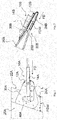
- a static discharger 10 according to a first embodiment of the present application is described with reference to Fig. 3 and Fig. 4 .
- Fig. 3 is an exploded perspective view showing a static discharger according to the first embodiment of the present application
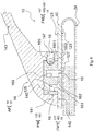
- Fig. 4 is a longitudinal section view showing the static discharger according to the first embodiment of the present application.
- the static discharger 10 may include a basement 12, a discharging portion 14 and an internal-media 16. It is to be noted herein that the assembly of the discharging portion 14 and the internal-media 16 corresponds to a discharger body AP according to the present application.
- the basement 12 may be a substantially rectangular shape plate (such as a rectangular plate with rounded corners), and is adapted to be installed (via a lower surface 123 thereof), for example, on a trailing edge profile member 24 (referring to Fig. 4 ) of a rudder and/or an elevator of an airplane.
- the flat plate configuration of the basement 12 can facilitate stable installation and electrical contact of the static discharger.
- the trailing edge profile member 24 serves as a supporting and conductive structure according to the present application.
- a (circular) protrusion 125 protruding upwardly from the upper surface 121 is provided.
- the protrusion 125 is adapted to be inserted in a (circular) shaft hole 161 formed in a bottom portion of the internal-media 16, which will be described hereinafter.
- a drilling trajectory line 129 is denoted on at least the upper surface 121 of the basement 12 (referring to Fig. 7 which is a schematic view showing bore arrangement on the basement according to the first embodiment of the present application).
- the drilling trajectory line 129 is a circular arc trajectory (which has a radius R corresponding to a distance D between the shaft hole and a fastening hole of the internal-media 16, which will be described hereinafter) centered on a site C (which corresponds to a center line of the protrusion 125 or a center 161C of the shaft hole 161).
- the drilling trajectory line 129 facilities the determination of a position of the bore on the basement 12 to facilitate an accurate assembly/installation of the static discharger 10.
- the discharging portion 14 may include a connection portion 141 and a tail portion 143.
- a receiving groove 145 (referring to Fig. 4 and Fig. 8 which is a perspective view showing the discharging portion according to the first embodiment of the present application) is formed in a bottom portion of the connection portion 141.
- the receiving groove 145 is of a substantially cuboid profile and is adapted to receiving the internal-media 16.
- An anchoring hole 147 (with or without threads) in communication with the receiving groove 145 is formed in a rear portion of the connection portion 141 (corresponding to a leeward portion according to the present application) (referring to Fig. 4 and Fig. 8 ).
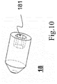
- An anchoring member 18, such as a self-locking screw, may pass through the anchoring hole 147, such that a front end of the anchoring member 18 is inserted in a recess at a rear portion of the internal-media 16 to thereby fasten the discharging portion 14 to the internal-media 16 and then to the basement 12. Referring to Fig. 10 (Fig.
- a driving hole 181 may be formed in a rear portion of the anchoring member 18.
- the driving hole 181 is adapted to receive driving tools such as a screwing tool such that the anchoring member 18 is, for example, screwed into the recess at the rear portion of the internal-media 16.
- a front side (the left side in Fig. 3 , that is, the windward side) of the discharging portion 14 which includes the connection portion 141 and the tail portion 143 is formed to have a streamline profile in accordance with the aerodynamic characteristics.
- the internal-media 16 may have a substantially cuboid profile, and is adapted to be fittingly (in a shape-matched manner) received in the receiving groove 145 of the discharging portion 14. Therefore, when the discharging portion 14 is arranged on the internal-media 16, because of non-circular or polyhedral profile matching between the internal-media 16 and the receiving groove 145, the rotation of the discharging portion 14 with respect to the internal-media 16 can be reliably restricted.
- the height of the internal-media 16 may be (slightly) smaller than the depth of the receiving groove 145, such that when the discharging portion 14 is arranged on the internal-media 16, there is a gap between a top surface of the internal-media 16 and a bottom surface of the receiving groove 145.
- a lower surface 142 of the connecting portion 141 of the discharging portion 14 can be sufficiently in contact with the upper surface 121 of the basement 12, enhancing installation stability and improving electrical contact.
- a (circular) shaft hole 161 is formed at a front region (corresponding to a first region according to the present application, and a rear region of the bottom portion corresponding to a second region according to the present application) of the bottom portion of the internal-media 16 (reference may be made to Fig. 9 which is a bottom view showing an internal-media according to the first embodiment of the present application).
- the shaft hole 161 is adapted to receive the (circular) protrusion 125 of the basement 12.
- the protrusion 125 and the shaft hole 161 together constitute a pivoting mechanism PM according to the present application.
- the height of the protrusion 125 may be (slightly) smaller than the depth of the shaft hole 161, such that when the internal-media 16 is arranged on the basement 12, there is a gap between a top surface of the protrusion 125 and a bottom surface of the shaft hole 161. Therefore, it can be reliably ensured that a lower surface 162 of the internal-media 16 is sufficiently in contact with the upper surface 121 of the basement 12, enhancing installation stability and improving electrical contact.
- the shaft hole 161 is formed to be a blind hole, and in other examples, the shaft hole may also be formed to be a through-hole.
- an inner diameter 161D of the shaft hole 161 is set such that the shaft hole 161 and the protrusion 125 can be in a small clearance fit and that the protrusion 125 of the basement 12 is adapted to bear a shear load.
- a fastening hole (a threaded hole) 163 is formed in a substantially longitudinally middle region or a rear region located more rearwardly than the middle region of the internal-media 16.
- the fastening hole 163 may be a through hole, and in other examples, the fastening hole 163 may be a blind hole.
- a fastener 19, for example a countersunk bolt, can pass through the basement 12 to threadedly engage to the fastening hole 163, thereby fastening the internal-media 16 to the basement 12.
- a recess 165 (for example, a conical recess 165) is formed at a center position of a rear portion (corresponding to a leeward portion according to the present application) of the internal-media 16.
- the front end of the anchoring member 18 as mentioned above may be inserted in the recess 165, to fasten the discharging portion 14 to the internal-media 16 and thus to the basement 12.
- the recess 165 is adapted to guide the self-tapping insertion of the anchoring member 18 such as a self-locking screw to thereby facilitate fastening the discharging portion 14 to the internal-media 16 via the anchoring member 18.
- a taper angle of the conical recess 165 may be 100 degrees or around 100 degrees (see Fig. 9 ).
- the shaft hole 161, the fastening hole 163 and the recess 165 are aligned in a longitudinal direction of the internal-media 16 and are positioned at a transversely middle position of the internal-media 16 (as clearly shown in Fig. 9 ).
- the basement 12 and the discharging portion 14 of the static discharger 10 are not fixedly assembled or integrally formed with each other, but is provided in an unassembled state as shown in Fig. 3 .
- the installation/assembly manner of the basement 12 and then the whole static discharger 10 will be determined based on practical circumstances such as dimension and orientation of the trailing edge profile member 24 of the rudder and/or the elevator of the airplane.
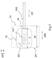
- a width W of the trailing edge profile member 24 is larger than or equal to a length L of the basement 12 (as shown in Fig. 5 which is a schematic view which illustrates a circumstance in which a static discharger according to the first embodiment of the present application is installed on a trailing edge profile member of a rudder and/or an elevator of an airplane)
- the basement 12 may be installed on the trailing edge profile member 24 in such a way that a longitudinal direction LD of the basement 12 is in line with a width direction WD of the trailing edge profile member 24.
- the width W of the trailing edge profile member 24 is smaller than the length L of the basement 12 (as shown in Fig.
- the basement 12 may be installed on the trailing edge profile member 24 in such a way that the longitudinal direction LD of the basement 12 intersects with or even is perpendicular to the width direction WD of the trailing edge profile member 24, such that the basement 12 can be completely superposed on the (flat) trailing edge profile member 24 to thereby avoid the so called (partially) suspended installation manner or bestriding installation manner.
- a suitable installation orientation of the discharging portion 14 with respect to the basement 12 is determined. It is to be noted herein that since the rotation of the discharging portion 14 with respect to the internal-media 16 is restricted, an installation orientation of the discharging portion 14 with respect to the basement 12 corresponds to that of the internal-media 16 with respect to the basement 12.
- the discharging portion 14 and the internal-media 16 are oriented such that a longitudinal direction of the discharging portion 14 and the internal-media 16 is in line with a longitudinal direction LD of the basement 12.
- drilling is performed at a middle position CN of the basement 12 (referring to Fig. 7 ).
- the flight direction FD of the airplane deviates (upwardly or downwardly) from the width direction WD of the trailing edge profile member 24 (referring to a flight direction UPFD and a flight direction LWFD in Fig.
- the discharging portion 14 and the internal-media 16 are oriented such that the longitudinal direction of the discharging portion 14 and the internal-media 16 accordingly deviates from the longitudinal direction LD of the basement 12.
- the flight direction FD deviates upwardly (such as the flight direction UPFD in Fig. 6 which deviates upwardly from the flight direction CNFD by an angle A)
- drilling will be performed at a position UP, which deviates upwardly with respect to the middle position CN, of the basement 12 (referring to Fig. 7 ); and in the case that the flight direction FD deviates downwardly (such as the flight direction LWFD in Fig.
- drilling will be performed at a position LW, which deviates downwardly with respect to the middle position CN, of the basement 12 (referring to Fig. 7 ).
- the middle position CN, the upper deviating position UP and the lower deviating position LW are all located on a circular arc drilling trajectory denoted by the drilling trajectory line 129.
- the assembly course of the static discharger 10 and the installation course for installing the static discharger 10 on the trailing edge profile member 24 can begin.
- a bore 127 is drilled in the basement 12 on the installation site (referring to Fig. 4 ) based on the determined drilling position (for example the middle position CN, the upper deviating position UP or the lower deviating position LW).
- the bore 127 allows the fastener 19 to pass through the basement 12 and is adapted to finally receive a head portion of the fastener 19.
- the internal-media 16 is arranged on the basement 12 such that the protrusion 125 is inserted in the shaft hole 161. Then, the internal-media 16 is pivoted about the protrusion 125, until the fastening hole 163 coincides with the bore 127. Then, the fastener 19 is passed through the bore 127 to threadedly engage to the fastening hole 163.
- an assembly of the basement 12 with the internal-media 16 is installed to, for example, the trailing edge profile member 24 of the rudder and/or the elevator of the airplane based on the determined installation orientation of the basement 12 with respect to the trailing edge profile member 24.
- the basement 12 is fixedly connected to the trailing edge profile member 24 via fasteners 40 such as a countersunk bolt as shown in Fig. 5 .
- the discharging portion 14 is arranged on the internal-media 16 such that the internal-media 16 is received in the receiving groove 145 of the discharging portion 14.
- the anchoring member 18, such as a self-locking screw is passed through the anchoring hole 147 and then inserted in the recess 165 at the rear portion of the internal-media 16, to thereby fasten the discharging portion 14 to the internal-media 16, to the basement 12 and then to the trailing edge profile member 24.
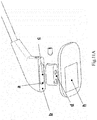
- Fig. 11A and Fig. 11B are respectively a schematic view illustrating an electrical conductivity route of a static discharger according to the first embodiment of the present application.
- the electrical conductivity routes may include a first route, a second route and a third route.
- the first route is: a conductive point "a" of a front wall of the receiving groove 145 of the discharging portion 14 --- a conductive point "e” of a front side of the internal-media 16 --- a conductive point “d” of the lower surface 162 of the internal-media 16 --- a conductive point "g” of the upper surface 121 of the basement 12 --- a conductive point "h” of the lower surface 123 of the basement 12 --- a conductive point "i” of the trailing edge profile member 24.
- the second route is: a conductive point "b" of a lower surface 142 of the connecting portion 141 of the discharging portion 14 --- the conductive point "g” of the upper surface 121 of the basement 12 --- the conductive point “h” of the lower surface 123 of the basement 12 --- the conductive point "i” of the trailing edge profile member 24.
- the third route is: a conductive point "c" of a side wall of the receiving groove 145 of the discharging portion 14 --- a conductive point "f” of a lateral side of the internal-media 16 --- the conductive point “d” of the lower surface 162 of the internal-media 16 --- the conductive point "g” of the upper surface 121 of the basement 12 --- the conductive point “h” of the lower surface 123 of the basement 12 --- the conductive point "i” of the trailing edge profile member 24.
- the basement and the discharging portion are not fixedly assembled or integrally formed with each other. Therefore, the installation/assembly manner of the basement and then the whole static discharger can be determined on the installation site based on practical circumstances such as dimension and orientation of the trailing edge profile member of the rudder and/or the elevator of the airplane, such that the basement and then the whole static discharger can be flexibly adapted to, for example, the relatively narrow trailing edge profile member of the rudder and/or the elevator. And in particular, the angle of the discharging portion with respect to the basement and to the trailing edge profile member can be flexibly adjusted based on the practical circumstance on the installation site. Therefore, it is easy to ensure that the discharging portion is installed in line with the flight direction. Thus, the universality of the static discharger is increased, and there is no need to prepare a series of different static dischargers for different models of airplane and installation positions etc.
- the angle of the discharging portion with respect to the basement and to the trailing edge profile member can be flexibly adjusted based on the practical circumstance on the installation site, and thus it is easy to ensure that the discharging portion is installed in line with the flight direction.
- the manner of fitting between the protrusion 125 of the basement 12 and the shaft hole 161 of the internal-media 16 and the manner of fitting between the fastener 19 and the fastening hole 163 of the internal-media 16 are appropriately designed (for example an appropriately designed fit tolerance), such that the protrusion 125 of the basement 12 is adapted to bear a shear load, and the fastener 19 is adapted to bear a tensile load, thereby effectively improving installation firmness of the static discharger 10.
- Fig. 12 is an exploded perspective view showing relevant components of a static discharger according to the second embodiment of the present application.
- a (circular) protrusion 125' protruding upwardly from an upper surface 121' of a basement 12' is provided at a substantially central region of the upper surface 121'. Accordingly, a (circular) shaft hole 161' is formed in a substantially central region of a bottom portion of an internal-media 16'.
- the protrusion125' and the shaft hole 161' together constitute a pivoting mechanism PM' according to the present application.
- two fastening holes (threaded holes) 163' are respectively formed on front and rear sides of the internal-media 16' with respect to the shaft hole 161'.
- distances from the two fastening holes 163' to the shaft hole 161' are equal and are spaced apart at 180 degrees.
- two corresponding bores (not shown in the figures) will be drilled on the circular arc drilling trajectory of the basement 12 on the installation site, and two corresponding fasteners 19', for example countersunk bolts, are equipped.
- the numbers of the fastening hole 163', the corresponding bores and the corresponding fasteners 19' may also each be three or more.
- the static discharger according to the present application may allow for many different variants.
- a (conical) recess 165 is formed at the center position of the rear portion of the internal-media 16 in order to guide a self-tapping insertion of the anchoring member 18 such as a self-locking screw.
- a cutout 165" is formed by substantially vertically truncating a lower portion of a rear portion of the internal-media 16" and beveling an upper portion of the rear portion of the internal-media 16" (as shown in Fig. 13 ).
- a lower wall of the cutout 165" is a substantially vertical flat wall, compared to the above conical recess 165, the following circumstance can be avoided: in the presence of an inappropriate manufacturing error, when the discharging portion 14 is fastened to the internal-media 16 via the anchoring member 18, the discharging portion 14 is forced to deviate upwardly such that the lower surface 142 of the connecting portion 141 is not in sufficient contact with the upper surface 121 of the basement 12. Specifically, referring to Fig.
- the basement is a substantially rectangular shape plate (such as a rectangular plate with rounded corners).
- suitable shapes of the basement may be conceived, such as, a square plate and a circular plate.
- the internal-media has a substantially cuboid profile.
- other suitable profiles of the internal-media may be conceived, for example a geometry with a square or truncated circular cross-section viewed from above.
- the receiving groove 145 is accordingly varied to allow the internal-media to adapt to fittingly (in a shape-matched manner) received in the receiving groove 145, such that the rotation of the discharging portion 14 with respect to the internal-media is reliably restricted.
- a bore is drilled in the basement on the installation site.
- a basement in which a series of bores are pre-drilled along the circular arc drilling trajectory, is provided.
- a protrusion is provided at the basement, and a shaft hole is provided at the internal-media.
- other arrangement in which the position of the protrusion and the position of the shaft hole are exchanged, can be conceived.
- the fastener passes through the bore of the basement to threadedly engage to the threaded fastening hole in the internal-media.
- the fastening hole is a hole without threads and a nut is employed to engage with threads on a front end of the fastener.
- the fastener passes through the fastening hole in the internal-media and then is threadedly engaged with a nut located below the bore of the basement.
- the fixing structure of the discharging portion and the internal-media (that is, the recess/cutout and the anchoring hole and the like) is provided at the leeward side of the static discharger.
- the fixing structure of the discharging portion and the internal-media can also be provided on other positions, for example, it can be provided at the front portion (the windward side) or the top portion of the connecting portion of the discharging portion.
- other suitable fixing structures can be employed instead of the self-locking screw fixing structure.
- the anchoring hole of the discharging portion can vertically coincide with the shaft hole or the fastening hole, which is provided as through holes, such that the upper portion of the shaft hole or the fastening hole can be configured to receive the front end of the anchoring member.
- a recess or the like which is additionally provided for receiving the front end of the anchoring member can be omitted.
- the discharging portion and the internal-media are separately formed and then are fixedly connected.
- the fastening hole 19 can be formed to be a blind hole or a through hole which penetrates through the connecting portion of the discharging portion.
- the fixing structure of the discharging portion and the internal-media and the like can be omitted.
- the static discharger is applied to the airplane.
- the static discharger according to the present application may also be applied to other aircrafts or even high-speed moving bodies such as a train and an automobile.
- high-speed moving bodies such as the airplane, the aerospace plane, the train and the automobile serve as a moving body according to the present application.
- the first fixing mechanism FM1 according to the present application includes the bore 127, the fastening hole 163/163' and the fastener 19, and the second fixing mechanism FM2 according to the present application includes the anchoring hole 147, the recess 165/the cutout 165', and the anchoring member 18.
- other suitable means can be employed to replace the first fixing mechanism FM1 and the second fixing mechanism FM2, for example welding and adhering.
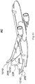
- an aircraft AC (referring to Fig. 14 which is a schematic view showing an aircraft according to the present application) including the above mentioned static discharger 10, 10' is further provided.
- the static discharger 10, 10' may be provided at a trailing edge (for example, a trailing edge profile member 24) of an elevator 20E, a trailing edge (for example, a trailing edge profile member 24) of a rudder 20R, a trailing edge (for example, a trailing edge profile member 24) of an aileron 20AL of the wing, or a trailing edge (for example, a trailing edge profile member 24) of a winglet 20W of the wing.
- a trailing edge for example, a trailing edge profile member 24
- orientation terms such as “up”, “down”, “top”, “bottom”, “vertical”, “transverse”, “lateral” and so on, is merely for description purpose, and should not be regarded as a limitation.
- the upper surface of the basement described in relation to a static discharger installed on an elevator is changed into a left/right side surface in the geographical sense described in relation to a static discharger installed on a rudder because the static discharger is rotated at 90 degrees.
- orientation term “front” generally corresponds to the nose direction of the airplane and the orientation term “rear” generally corresponds to tail direction of the airplane.
Landscapes
- Engineering & Computer Science (AREA)
- Aviation & Aerospace Engineering (AREA)
- Elimination Of Static Electricity (AREA)
Description
- The present application relates to a static discharger and an aircraft having the same, and more particularly to a static discharger improved in aspects of installation adaptation and universality and so on.
- Generally, high-speed moving bodies such as the airplane, the aerospace plane, the train and the automobile are provided with a static discharger. In particular, the static discharger is an essential component in the airplane used to protect relevant structures of the airplane by discharging the current (static electricity) to the air slowly. The static discharger may be installed at the wing (for example, a trailing edge of the outboard aileron and/or a trailing edge of the winglet), the VTP (vertical fin plane), the HTP (horizontal fin plane), the rudder and/or the elevator.
- Referring to
Fig. 1 (Fig. 1 is a schematic view for illustrating a situation where a static discharger according to the relevant technology is installed on a rudder of an airplane), thestatic discharger 10A according to the relevant technology includes abasement 12A and adischarging portion 14A. Thestatic discharger 10A is installed on therudder 20A (only a part of therudder 20A is shown inFig. 1 ) of the airplane. Generally, thebasement 12A is a substantially rectangular plate. Thedischarging portion 14A is fixedly installed at or integrally formed at a transversely middle position of thebasement 12A along a longitudinal direction of thebasement 12A. Therudder 20A is provided, at atrailing edge 22A thereof, with a trailingedge profile member 24A which is made of metal. The trailingedge profile member 24A generally has a U-shaped cross section and is configured to envelop thetrailing edge 22A of therudder 20A (inFig. 1 , the trailingedge profile member 24A envelops thetrailing edge 22A of therudder 20A from the right side). With thebasement 12A of thestatic discharger 10A being installed on the trailingedge profile member 24A of therudder 20A, thestatic discharger 10A is mechanically fixed to therudder 20A and at the same time conductively connected to therudder 20A (that is, to the trailingedge profile member 24A) and thus to other relevant structures of the airplane. - On the one hand, according to the design requirements of the airplane, a width FDW of the trailing
edge profile member 24A along the flight direction FD of the airplane is generally small. On the other hand, In order to ensure stable installation and sufficient electrical contact area of thestatic discharger 10A, the area and then the length L of thebasement 12A should not be too small, and therefore, the length L of thebasement 12A is generally larger than the width FDW of the trailingedge profile member 24A. On still another aspect, in order to minimize the windage caused by thedischarging portion 14A and to minimize the force (the wind force) suffered by thedischarging portion 14A, it is required that thedischarging portion 14A be installed in a direction in line with the flight direction FD (for example, in the example shown inFig. 1 , thestatic discharger 10A and thedischarging portion 14A thereof should be orientated in the way shown in the figure with respect to therudder 20A). - Therefore, as shown in
Fig. 1 , in thestatic discharger 10A according to the relevant technology, in order to avoid instable installation and/or poor electrical contact caused by the condition in which thebasement 12A of thestatic discharger 10A is directly installed to the trailingedge profile member 24A in a partially suspended manner, an additionalmetallic plate 30A is needed via which thestatic discharger 10A is installed on therudder 20A (themetallic plate 30A is directly installed on the trailingedge profile member 24A in a partially suspended manner, and then thebasement 12A is installed on themetallic plate 30A by afastener 40A). - In this way, in the
static discharger 10A according to the relevant technology, since an additionalmetallic plate 30A is needed for the installation, the weight is increased, the installation is complex, and the aerodynamic surface is affected. In addition, the partially suspended installations of themetallic plate 30A and thebasement 12A may also affect the aerodynamic surface (which will cause turbulence effect) and cause inconvenient installation. Still another, the structure in which thedischarging portion 14A is fixedly connected to or integrally formed with thebasement 12A may cause a problem that thestatic discharger 10A (in particular, thebasement 12A) cannot be flexibly adapted to the trailingedge profile member 24A of therudder 20A which is relatively narrow, and particularly, the angles of thedischarging portion 14A with respect to thebasement 12A and to therudder 20A (the trailingedge profile member 24A) cannot be flexibly adjusted based on the practical situation on the installation site, and thus it is difficulty to ensure that thedischarging portion 14A is installed in line with the flight direction FD. - Referring to
Fig. 2 (Fig. 2 is a schematic view which illustrates a situation where another static discharger according to the relevant technology is installed on an elevator of an airplane), thestatic discharger 10B according to the relevant technology may also include abasement 12B and adischarging portion 14B. Thedischarging portion 14B is installed on theelevator 20B. - In the
static discharger 10B according to the relevant technology, similarly, a length L of thebasement 12B is generally larger than a width FDW of a trailingedge profile member 24B of theelevator 20B along the flight direction FD of the airplane. As shown inFig. 2 , thestatic discharger 10B is installed to theelevator 20B in a manner different from the partially suspended manner shown inFig. 1 . However, in this different installing manner, it also need an additionalmetallic plate 30B to improve the electrical contact between thestatic discharger 10B and theelevator 20B (the trailingedge profile member 24B), and to fill up theintersection region 28B, which is generally concave, between the trailingedge profile member 24B of theelevator 20B and thebody region 26B of theelevator 20B, to ensure stable installation of thestatic discharger 10B. - In this way, in the
static discharger 10B according to the relevant technology, similarly, since an additionalmetallic plate 30B is needed for the installation, the weight is increased, the installation is complex, and the aerodynamic surface is affected. In addition, since themetallic plate 30B and thebasement 12B not only are installed on the trailingedge profile member 24B but also go upward and are installed on thebody region 26B of theelevator 20B (which is also called as a bestriding installation manner), themetallic plate 30B and thebasement 12B protrude upward at a higher degree, which not only affect the aerodynamic surface but also cause inconvenient installation. Still another, similarly, the structure in which thedischarging portion 14B is fixedly connected to or integrally formed with thebasement 12B may cause a problem that thestatic discharger 10B (in particular, thebasement 12B) cannot be flexibly adapted to the trailingedge profile member 24B of theelevator 20B which is relatively narrow, and particularly, the angles of thedischarging portion 14B with respect to thebasement 12B and to theelevator 20B (the trailingedge profile member 24B) cannot be flexibly adjusted based on the practical situation on the installation site, and thus it is difficulty to ensure that thedischarging portion 14B is installed in line with the flight direction FD. -
US 4,262,321 A discloses a discharger which includes a mounting structure formed as a sub-base having a lower surface provided with downwardly extending conical projections terminating in points which engage the underlying graphite composite surface and form electrical contact therewith, providing for the mounting of the sub-base to the composite surface by conventional non-conductive epoxy. - Herein, it is to be noted that the technical contents in this section are provided to help the person skilled in the art to understand the present application, and they do not necessarily constitute a part of the prior art.
- A general concept of the present application is provided in this section, but this section does not involve a complete scope of the present application or an overall disclosure of all the features of the present application.
- An object of the present application is to provide a static discharger with which an installation/assembly manner of a basement and then the whole static discharger can be determined based on the practical circumstance on the installation site.
- Another object of the present application is to provide a static discharger with which a basement and then the whole static discharger can be flexibly adapted to a trailing edge profile member which is relatively narrow.
- Another object of the present application is to provide a static discharger with which an angle of a discharging portion with respect to a basement and to a trailing edge profile member can be flexibly adjusted based on the practical circumstance on the installation site, thereby making it easy to ensure that the discharging portion is installed to be in line with a flight direction.
- Another object of the present application is to provide a static discharger with which the universality of the static discharger can be improved and thus there is no need to prepare a series of different static dischargers for different airplane models and installation positions etc.
- Another object of the present application is to provide a static discharger with which disadvantageous circumstances such as that the weight is increased, the assembly is complex and the aerodynamic surface is affected can be avoided.
- Another object of the present application is to provide a static discharger with which the electrical contact can be improved.
- In order to achieve one or more of the above objects, according to an aspect of the present application, a static discharger is provided including: a basement adapted to be installed to a supporting and conductive structure of a moving body; and a discharger body adapted to be installed to the basement. The static discharger further includes a first fixing mechanism adapted to fix the discharger body to the basement. A pivoting mechanism is provided between the basement and the discharger body, the pivoting mechanism allowing the discharger body to pivot with respect to the basement so as to adjust an installation orientation of the discharger body with respect to the basement during an on-site-installation of the static discharger.
- In the static discharger according to the present application, the pivoting mechanism includes a protrusion and a shaft hole adapted to receive the protrusion, the protrusion protrudes out of one of the basement and the discharger body, and the shaft hole is formed at the other of the basement and the discharger body.
- In the static discharger according to the present application, the discharger body includes a discharging portion and an internal-media.
- In the static discharger according to the present application, the discharging portion includes a connecting portion and a tail portion.
- In the static discharger according to the present application, a receiving groove is formed in a bottom portion of the connecting portion, and the receiving groove is adapted to receive the internal-media.
- In the static discharger according to the present application, a shape of the receiving groove and a shape of the internal-media are configured such that the internal-media is adapted to be received in the receiving groove in a shape-matched manner so as to restrict the rotation of the discharging portion with respect to the internal-media.
- In the static discharger according to the present application, the height of the internal-media is smaller than the depth of the receiving groove, so that when the discharging portion is arranged on the internal-media, there is a gap between a top surface of the internal-media and a bottom surface of the receiving groove.
- In the static discharger according to the present application, the protrusion protrudes out of the basement and the shaft hole is formed at the internal-media.
- In the static discharger according to the present application, the shaft hole is formed to be a blind hole, and the height of the protrusion is smaller than the depth of the shaft hole, such that when the internal-media is arranged on the basement, there is a gap between a top surface of the protrusion and a bottom surface of the shaft hole.
- In the static discharger according to the present application, an inner diameter of the shaft hole and an outer diameter of the protrusion are set such that the shaft hole and the protrusion are in a small-clearance fit and that the protrusion is adapted to bear a shear load.
- In the static discharger according to the present application, the protrusion protrudes upwardly from either of a first side and a second side of an upper surface of the basement, and the shaft hole is formed in a corresponding one of a first region and a second region of a bottom portion of the internal-media.
- In the static discharger according to the present application, the first fixing mechanism includes a fastening hole, and the fastening hole is formed in a substantially middle region of the internal-media or formed in one, where the shaft hole is not formed, of the first region and the second region.
- In the static discharger according to the present application, the protrusion protrudes upwardly from a substantially central region of an upper surface of the basement, and the shaft hole is formed in a substantially central region of a bottom portion of the internal-media.
- In the static discharger according to the present application, the first fixing mechanism includes two fastening holes, and the fastening holes are formed in the internal-media around the shaft hole.
- In the static discharger according to the present application, the fastening hole is a threaded through-hole, and the first fixing mechanism further includes a countersunk bolt, and the countersunk bolt is adapted to pass through the basement to threadedly engage with the fastening hole.
- In the static discharger according to the present application, the basement is a rectangular plate with rounded corners, a square plate or a circular plate.
- In the static discharger according to the present application, a drilling trajectory line is denoted on at least the upper surface of the basement, the drilling trajectory line is a circular arc trajectory centered on a site, and the site corresponds to a center line of the protrusion or a center of the shaft hole, and a radius of the circular arc trajectory corresponds to a distance between the shaft hole and the fastening hole.
- In the static discharger according to the present application, the first fixing mechanism further includes a bore, and a drilling position which is determined for drilling the bore during the on-site-installation is located on the drilling trajectory line.
- In the static discharger according to the present application, the first fixing mechanism further includes a countersunk bolt, and the bore allows the countersunk bolt to pass through the basement and is adapted to receive a head portion of the countersunk bolt.
- In the static discharger according to the present application, the static discharger further includes a second fixing mechanism adapted to fix the discharging portion to the internal-media.
- In the static discharger according to the present application, the second fixing mechanism includes: an anchoring hole formed in a leeward portion of the connecting portion and being in communication with the receiving groove; a conical recess centrally formed in a leeward portion of the internal-media; and an anchoring member, and the conical recess is adapted to receive a front end of the anchoring member passing through the anchoring hole.
- In the static discharger according to the present application, the second fixing mechanism includes: an anchoring hole formed in a leeward portion of the connecting portion and being in communication with the receiving groove; a cutout; and an anchoring member, and the cutout is formed by substantially vertically truncating a lower portion of a leeward portion of the internal-media and beveling an upper portion of the leeward portion of the internal-media.
- In the static discharger according to the present application, the anchoring member is a self-locking screw, and a driving hole adapted to receiving a driving tool is formed in a rear portion of the anchoring member.
- In the static discharger according to the present application, a windward side of the discharging portion is formed to have a streamline profile in accordance with aerodynamic characteristics.
- In order to achieve one or more of the above objects, according to another aspect of the present application, an aircraft is provided. The aircraft includes the static discharger as described above.
- In the aircraft according to the present application, the static discharger is provided at a trailing edge profile member, which is configured as the supporting and conductive structure, of an elevator, a rudder, an aileron of a wing and/or a winglet of the wing of the aircraft.
- According to the present application, when the static discharger is taken away from the factory, the basement and the discharging portion are not fixedly assembled or integrally formed with each other. Therefore, the installation/assembly manner of the basement and then the whole static discharger can be determined on the installation site based on practical circumstances such as dimension and orientation of the trailing edge profile member of the rudder and/or the elevator of the airplane, such that the basement and then the whole static discharger can be flexibly adapted to, for example, the relatively narrow trailing edge profile member of the rudder and/or the elevator. And in particular, the angle of the discharging portion with respect to the basement and to the trailing edge profile member can be flexibly adjusted based on the practical circumstance on the installation site. Therefore, it is easy to ensure that the discharging portion is installed in line with the flight direction. Thus, the universality of the static discharger is increased, and there is no need to prepare a series of different static dischargers for different models of airplane and installation positions etc.
- In addition, according to the present application, since no additional installation member such as a metallic plate is needed in the installation of the static discharger, disadvantageous circumstances such as that the weight is increased, the assembly is complex and the aerodynamic surface is affected can be avoided. Besides, the so called suspended installation manner or bestriding installation manner can be avoided since generally the basement can be completely superposed on the flat trailing edge profile member, thus the electrical contact can be improved, the installation course can be further simplified and the affection on the aerodynamic surface can be further reduced.
- Features and advantages of one or more embodiments of the present application will be understood more readily with reference to the description in conjunction with the drawings, and wherein:
-
Fig. 1 is a schematic view for illustrating a situation where a static discharger according to the relevant technology is installed on a rudder of an airplane; -
Fig. 2 is a schematic view which illustrates a situation where another static discharger according to the relevant technology is installed on an elevator of an airplane; -
Fig. 3 is an exploded perspective view showing a static discharger according to a first embodiment of the present application; -
Fig. 4 is a longitudinal section view showing the static discharger according to the first embodiment of the present application; -
Fig. 5 is a schematic view which illustrates a situation where the static discharger according to the first embodiment of the present application is installed on a trailing edge profile member of a rudder and/or an elevator of an airplane; -
Fig. 6 is a view showing an installation orientation of the discharging portion with respect to the basement according to the first embodiment of the present application; -
Fig. 7 is a schematic view showing bore arrangement on the basement according to the first embodiment of the present application; -
Fig. 8 is a perspective view showing the discharging portion according to the first embodiment of the present application; -
Fig. 9 is a bottom view showing an internal-media according to the first embodiment of the present application; -
Fig. 10 is a perspective view showing an anchoring member according the first embodiment of the present application; -
Fig. 11A andFig. 11B are respectively a schematic view illustrating an electrical conductivity route of the static discharger according to the first embodiment of the present application; -
Fig. 12 is an exploded perspective view showing relevant components of a static discharger according to a second embodiment of the present application; -
Fig. 13 is a perspective view of an internal-media according to a variation; and -
Fig. 14 is a schematic view showing an aircraft according to the present application. - Hereinafter, the present application will be described in detail with reference to the drawings and in conjunction with the exemplary embodiments. The following detailed description is for illustration purpose only but is not intended to limit the present application and its application or usage.
- Firstly, a
static discharger 10 according to a first embodiment of the present application is described with reference toFig. 3 andFig. 4 .Fig. 3 is an exploded perspective view showing a static discharger according to the first embodiment of the present application, andFig. 4 is a longitudinal section view showing the static discharger according to the first embodiment of the present application. - As shown in
Fig. 3 , thestatic discharger 10 may include abasement 12, a dischargingportion 14 and an internal-media 16. It is to be noted herein that the assembly of the dischargingportion 14 and the internal-media 16 corresponds to a discharger body AP according to the present application. - The
basement 12 may be a substantially rectangular shape plate (such as a rectangular plate with rounded corners), and is adapted to be installed (via alower surface 123 thereof), for example, on a trailing edge profile member 24 (referring toFig. 4 ) of a rudder and/or an elevator of an airplane. The flat plate configuration of thebasement 12 can facilitate stable installation and electrical contact of the static discharger. Here, it is to be noted that the trailingedge profile member 24 serves as a supporting and conductive structure according to the present application. - At a front region of an
upper surface 121 of the basement 12 (the left region inFig. 3 and it may correspond to a first side according to the present application, while a rear region of theupper surface 121 may correspond to a second side according to the present application), a (circular)protrusion 125 protruding upwardly from theupper surface 121 is provided. Theprotrusion 125 is adapted to be inserted in a (circular)shaft hole 161 formed in a bottom portion of the internal-media 16, which will be described hereinafter. - In some examples, a
drilling trajectory line 129 is denoted on at least theupper surface 121 of the basement 12 (referring toFig. 7 which is a schematic view showing bore arrangement on the basement according to the first embodiment of the present application). Thedrilling trajectory line 129 is a circular arc trajectory (which has a radius R corresponding to a distance D between the shaft hole and a fastening hole of the internal-media 16, which will be described hereinafter) centered on a site C (which corresponds to a center line of theprotrusion 125 or acenter 161C of the shaft hole 161). As will be described hereinafter, thedrilling trajectory line 129 facilities the determination of a position of the bore on thebasement 12 to facilitate an accurate assembly/installation of thestatic discharger 10. - The discharging
portion 14 may include aconnection portion 141 and atail portion 143. A receiving groove 145 (referring toFig. 4 andFig. 8 which is a perspective view showing the discharging portion according to the first embodiment of the present application) is formed in a bottom portion of theconnection portion 141. The receivinggroove 145 is of a substantially cuboid profile and is adapted to receiving the internal-media 16. - An anchoring hole 147 (with or without threads) in communication with the receiving
groove 145 is formed in a rear portion of the connection portion 141 (corresponding to a leeward portion according to the present application) (referring toFig. 4 andFig. 8 ). An anchoringmember 18, such as a self-locking screw, may pass through theanchoring hole 147, such that a front end of the anchoringmember 18 is inserted in a recess at a rear portion of the internal-media 16 to thereby fasten the dischargingportion 14 to the internal-media 16 and then to thebasement 12. Referring toFig. 10 (Fig. 10 is a perspective view showing an anchoring member according to the first embodiment of the present application), a drivinghole 181 may be formed in a rear portion of the anchoringmember 18. The drivinghole 181 is adapted to receive driving tools such as a screwing tool such that the anchoringmember 18 is, for example, screwed into the recess at the rear portion of the internal-media 16. - In some examples, a front side (the left side in
Fig. 3 , that is, the windward side) of the dischargingportion 14 which includes theconnection portion 141 and thetail portion 143 is formed to have a streamline profile in accordance with the aerodynamic characteristics. - The internal-
media 16 may have a substantially cuboid profile, and is adapted to be fittingly (in a shape-matched manner) received in the receivinggroove 145 of the dischargingportion 14. Therefore, when the dischargingportion 14 is arranged on the internal-media 16, because of non-circular or polyhedral profile matching between the internal-media 16 and the receivinggroove 145, the rotation of the dischargingportion 14 with respect to the internal-media 16 can be reliably restricted. - In some examples, as clearly shown in
Fig. 4 , the height of the internal-media 16 may be (slightly) smaller than the depth of the receivinggroove 145, such that when the dischargingportion 14 is arranged on the internal-media 16, there is a gap between a top surface of the internal-media 16 and a bottom surface of the receivinggroove 145. Thus, it can be reliably ensured that alower surface 142 of the connectingportion 141 of the dischargingportion 14 can be sufficiently in contact with theupper surface 121 of thebasement 12, enhancing installation stability and improving electrical contact. - A (circular)
shaft hole 161 is formed at a front region (corresponding to a first region according to the present application, and a rear region of the bottom portion corresponding to a second region according to the present application) of the bottom portion of the internal-media 16 (reference may be made toFig. 9 which is a bottom view showing an internal-media according to the first embodiment of the present application). Theshaft hole 161 is adapted to receive the (circular)protrusion 125 of thebasement 12. When the internal-media 16 is arranged on thebasement 12 in a state that theprotrusion 125 is inserted in theshaft hole 161, the internal-media 16 can pivot about the protrusion 125 (through 360 degrees). Herein, it is to be noted that theprotrusion 125 and theshaft hole 161 together constitute a pivoting mechanism PM according to the present application. - In some examples, the height of the
protrusion 125 may be (slightly) smaller than the depth of theshaft hole 161, such that when the internal-media 16 is arranged on thebasement 12, there is a gap between a top surface of theprotrusion 125 and a bottom surface of theshaft hole 161. Therefore, it can be reliably ensured that alower surface 162 of the internal-media 16 is sufficiently in contact with theupper surface 121 of thebasement 12, enhancing installation stability and improving electrical contact. In the illustrated example, theshaft hole 161 is formed to be a blind hole, and in other examples, the shaft hole may also be formed to be a through-hole. - In some examples, an
inner diameter 161D of theshaft hole 161 is set such that theshaft hole 161 and theprotrusion 125 can be in a small clearance fit and that theprotrusion 125 of thebasement 12 is adapted to bear a shear load. - A fastening hole (a threaded hole) 163 is formed in a substantially longitudinally middle region or a rear region located more rearwardly than the middle region of the internal-
media 16. In some examples, thefastening hole 163 may be a through hole, and in other examples, thefastening hole 163 may be a blind hole. Afastener 19, for example a countersunk bolt, can pass through thebasement 12 to threadedly engage to thefastening hole 163, thereby fastening the internal-media 16 to thebasement 12. - A recess 165 (for example, a conical recess 165) is formed at a center position of a rear portion (corresponding to a leeward portion according to the present application) of the internal-
media 16. The front end of the anchoringmember 18 as mentioned above may be inserted in therecess 165, to fasten the dischargingportion 14 to the internal-media 16 and thus to thebasement 12. Therecess 165 is adapted to guide the self-tapping insertion of the anchoringmember 18 such as a self-locking screw to thereby facilitate fastening the dischargingportion 14 to the internal-media 16 via the anchoringmember 18. Besides, the fixing structure of the dischargingportion 14 and the internal-media 16 is provided at the leeward side of thestatic discharger 10, which thereby can sustain the intact streamline profile of the windward side of thestatic discharger 10 to ensure that the leeward side of thestatic discharger 10 is in accordance with the aerodynamic characteristics. In some examples, a taper angle of theconical recess 165 may be 100 degrees or around 100 degrees (seeFig. 9 ). - In a preferred example, the
shaft hole 161, thefastening hole 163 and therecess 165 are aligned in a longitudinal direction of the internal-media 16 and are positioned at a transversely middle position of the internal-media 16 (as clearly shown inFig. 9 ). - Hereinafter, an exemplary assembly course of the
static discharger 10 according to the first embodiment of the present application and an exemplary installation course in which thestatic discharger 10 is installed, for example, on the trailingedge profile member 24 of the rudder and/or the elevator will be described. - According to the first embodiment of the present application, when the
static discharger 10 is taken away from the factory, thebasement 12 and the dischargingportion 14 of thestatic discharger 10 are not fixedly assembled or integrally formed with each other, but is provided in an unassembled state as shown inFig. 3 . On the installation site, the installation/assembly manner of thebasement 12 and then the wholestatic discharger 10 will be determined based on practical circumstances such as dimension and orientation of the trailingedge profile member 24 of the rudder and/or the elevator of the airplane. - In a case that a width W of the trailing
edge profile member 24 is larger than or equal to a length L of the basement 12 (as shown inFig. 5 which is a schematic view which illustrates a circumstance in which a static discharger according to the first embodiment of the present application is installed on a trailing edge profile member of a rudder and/or an elevator of an airplane), thebasement 12 may be installed on the trailingedge profile member 24 in such a way that a longitudinal direction LD of thebasement 12 is in line with a width direction WD of the trailingedge profile member 24. In a case that the width W of the trailingedge profile member 24 is smaller than the length L of the basement 12 (as shown inFig. 1 which shows a situation of the relevant technology), thebasement 12 may be installed on the trailingedge profile member 24 in such a way that the longitudinal direction LD of thebasement 12 intersects with or even is perpendicular to the width direction WD of the trailingedge profile member 24, such that thebasement 12 can be completely superposed on the (flat) trailingedge profile member 24 to thereby avoid the so called (partially) suspended installation manner or bestriding installation manner. - After a suitable installation manner of the
basement 12 with respect to the trailingedge profile member 24 is determined, a suitable installation orientation of the dischargingportion 14 with respect to thebasement 12 is determined. It is to be noted herein that since the rotation of the dischargingportion 14 with respect to the internal-media 16 is restricted, an installation orientation of the dischargingportion 14 with respect to thebasement 12 corresponds to that of the internal-media 16 with respect to thebasement 12. - Herein, the circumstance as shown in
Fig. 5 where the width W of the trailingedge profile member 24 is greater than or equal to the length L of thebasement 12 and thebasement 12 is installed in such a way that the longitudinal direction LD of thebasement 12 is in line with the width direction WD of the trailingedge profile member 24 is described as an example. In the case that a flight direction FD of an airplane is exactly in line with the width direction WD of the trailing edge profile member 24 (referring to a flight direction CNFD inFig. 6 which is a view showing an installation orientation of the discharging portion with respect to the basement according to the first embodiment of the present application), the dischargingportion 14 and the internal-media 16 are oriented such that a longitudinal direction of the dischargingportion 14 and the internal-media 16 is in line with a longitudinal direction LD of thebasement 12. In such case, drilling is performed at a middle position CN of the basement 12 (referring toFig. 7 ). In the case that the flight direction FD of the airplane deviates (upwardly or downwardly) from the width direction WD of the trailing edge profile member 24 (referring to a flight direction UPFD and a flight direction LWFD inFig. 6 for example), the dischargingportion 14 and the internal-media 16 are oriented such that the longitudinal direction of the dischargingportion 14 and the internal-media 16 accordingly deviates from the longitudinal direction LD of thebasement 12. In the case that the flight direction FD deviates upwardly (such as the flight direction UPFD inFig. 6 which deviates upwardly from the flight direction CNFD by an angle A), drilling will be performed at a position UP, which deviates upwardly with respect to the middle position CN, of the basement 12 (referring toFig. 7 ); and in the case that the flight direction FD deviates downwardly (such as the flight direction LWFD inFig. 6 which deviates downwardly from the flight direction CNFD by the angle A), drilling will be performed at a position LW, which deviates downwardly with respect to the middle position CN, of the basement 12 (referring toFig. 7 ). Herein, it is to be noted that the middle position CN, the upper deviating position UP and the lower deviating position LW are all located on a circular arc drilling trajectory denoted by thedrilling trajectory line 129. - After an installation orientation of the
basement 12 with respect to the trailingedge profile member 24 is determined, and after an installation orientation of the dischargingportion 14 with respect to thebasement 12 is determined (that is, after the drilling position on thebasement 12 is determined), the assembly course of thestatic discharger 10 and the installation course for installing thestatic discharger 10 on the trailingedge profile member 24 can begin. - Firstly, a
bore 127 is drilled in thebasement 12 on the installation site (referring toFig. 4 ) based on the determined drilling position (for example the middle position CN, the upper deviating position UP or the lower deviating position LW). Thebore 127 allows thefastener 19 to pass through thebasement 12 and is adapted to finally receive a head portion of thefastener 19. - Next, the internal-
media 16 is arranged on thebasement 12 such that theprotrusion 125 is inserted in theshaft hole 161. Then, the internal-media 16 is pivoted about theprotrusion 125, until thefastening hole 163 coincides with thebore 127. Then, thefastener 19 is passed through thebore 127 to threadedly engage to thefastening hole 163. - Next, an assembly of the
basement 12 with the internal-media 16 is installed to, for example, the trailingedge profile member 24 of the rudder and/or the elevator of the airplane based on the determined installation orientation of thebasement 12 with respect to the trailingedge profile member 24. In some examples, thebasement 12 is fixedly connected to the trailingedge profile member 24 viafasteners 40 such as a countersunk bolt as shown inFig. 5 . - Next, the discharging
portion 14 is arranged on the internal-media 16 such that the internal-media 16 is received in the receivinggroove 145 of the dischargingportion 14. Then, the anchoringmember 18, such as a self-locking screw, is passed through theanchoring hole 147 and then inserted in therecess 165 at the rear portion of the internal-media 16, to thereby fasten the dischargingportion 14 to the internal-media 16, to thebasement 12 and then to the trailingedge profile member 24. - As such, the assembly/installation course of the
static discharger 10 is completed. - Hereinafter, an electrical conductivity route of the
static discharger 10 according to an exemplary embodiment of the present application will be described with reference toFig. 11A andFig. 11B (Fig. 11A andFig. 11B are respectively a schematic view illustrating an electrical conductivity route of a static discharger according to the first embodiment of the present application). - In the
static discharger 10, there may be a plurality of electrical conductivity routes, which therefore can ensure an efficient static discharging. For example, the electrical conductivity routes may include a first route, a second route and a third route. The first route is: a conductive point "a" of a front wall of the receivinggroove 145 of the dischargingportion 14 --- a conductive point "e" of a front side of the internal-media 16 --- a conductive point "d" of thelower surface 162 of the internal-media 16 --- a conductive point "g" of theupper surface 121 of thebasement 12 --- a conductive point "h" of thelower surface 123 of thebasement 12 --- a conductive point "i" of the trailingedge profile member 24. The second route is: a conductive point "b" of alower surface 142 of the connectingportion 141 of the dischargingportion 14 --- the conductive point "g" of theupper surface 121 of thebasement 12 --- the conductive point "h" of thelower surface 123 of thebasement 12 --- the conductive point "i" of the trailingedge profile member 24. The third route is: a conductive point "c" of a side wall of the receivinggroove 145 of the dischargingportion 14 --- a conductive point "f" of a lateral side of the internal-media 16 --- the conductive point "d" of thelower surface 162 of the internal-media 16 --- the conductive point "g" of theupper surface 121 of thebasement 12 --- the conductive point "h" of thelower surface 123 of thebasement 12 --- the conductive point "i" of the trailingedge profile member 24. - According to the first embodiment of the present application, when the static discharger is taken away from the factory, the basement and the discharging portion are not fixedly assembled or integrally formed with each other. Therefore, the installation/assembly manner of the basement and then the whole static discharger can be determined on the installation site based on practical circumstances such as dimension and orientation of the trailing edge profile member of the rudder and/or the elevator of the airplane, such that the basement and then the whole static discharger can be flexibly adapted to, for example, the relatively narrow trailing edge profile member of the rudder and/or the elevator. And in particular, the angle of the discharging portion with respect to the basement and to the trailing edge profile member can be flexibly adjusted based on the practical circumstance on the installation site. Therefore, it is easy to ensure that the discharging portion is installed in line with the flight direction. Thus, the universality of the static discharger is increased, and there is no need to prepare a series of different static dischargers for different models of airplane and installation positions etc.
- In addition, according to the first embodiment of the present application, since no additional installation member such as a metallic plate is needed in the installation of the static discharger, disadvantageous circumstances such as that the weight is increased, the assembly is complex and the aerodynamic surface is affected can be avoided. Besides, the so called suspended installation manner or bestriding installation manner can be avoided since generally the basement can be completely superposed on the flat trailing edge profile member, thus the electrical contact can be improved, the installation course can be further simplified and the affection on the aerodynamic surface can be further reduced.
- It should be noted herein that according to the first embodiment of the present application, even though in a certain circumstance that the basement cannot be completely superposed on the trailing edge profile member by adjusting an installation orientation of the basement with respect to the trailing edge profile member, and the employment of the so called suspended installation manner or bestriding installation manner with or without an additional metallic plate cannot be avoided, since the suspended region/bestriding region can be properly reduced and then the additional metallic plate (in case that an additional metallic plate is employed) can be properly reduced, acceptable effects which are basically the same as or similar to the above advantageous technical effects can be obtained. In particular, even though in a certain circumstance that it is necessary to employ the so called suspended installation manner or bestriding installation manner with an additional metallic plate being used, the angle of the discharging portion with respect to the basement and to the trailing edge profile member can be flexibly adjusted based on the practical circumstance on the installation site, and thus it is easy to ensure that the discharging portion is installed in line with the flight direction.
- In addition, according to the first embodiment of the present application, the manner of fitting between the
protrusion 125 of thebasement 12 and theshaft hole 161 of the internal-media 16 and the manner of fitting between thefastener 19 and thefastening hole 163 of the internal-media 16 are appropriately designed (for example an appropriately designed fit tolerance), such that theprotrusion 125 of thebasement 12 is adapted to bear a shear load, and thefastener 19 is adapted to bear a tensile load, thereby effectively improving installation firmness of thestatic discharger 10. - Hereinafter, a static discharger 10' according to a second embodiment of the present application will be described with reference to
Fig. 12. Fig. 12 is an exploded perspective view showing relevant components of a static discharger according to the second embodiment of the present application. - For the sake of simplicity, only the main differences between the second embodiment and the first embodiment will be described.
- In the second embodiment, a (circular) protrusion 125' protruding upwardly from an upper surface 121' of a basement 12' is provided at a substantially central region of the upper surface 121'. Accordingly, a (circular) shaft hole 161' is formed in a substantially central region of a bottom portion of an internal-media 16'. Herein, it is to be noted that the protrusion125' and the shaft hole 161' together constitute a pivoting mechanism PM' according to the present application.
- In the second embodiment, two fastening holes (threaded holes) 163' are respectively formed on front and rear sides of the internal-media 16' with respect to the shaft hole 161'. In a preferable example, distances from the two fastening holes 163' to the shaft hole 161' are equal and are spaced apart at 180 degrees. Accordingly, two corresponding bores (not shown in the figures) will be drilled on the circular arc drilling trajectory of the
basement 12 on the installation site, and two corresponding fasteners 19', for example countersunk bolts, are equipped. Herein, it should be understood that the numbers of the fastening hole 163', the corresponding bores and the corresponding fasteners 19' may also each be three or more. - According to the second embodiment of the present application, technical effects similar to those of the first embodiment of the present application can be obtained. Also, according to the second embodiment, since a plurality of fastening holes 163' and a plurality of fasteners 19' are provided, the installation firmness of the static discharger 10' can be further improved.
- The static discharger according to the present application may allow for many different variants.
- In the above embodiment, it is described that a (conical)
recess 165 is formed at the center position of the rear portion of the internal-media 16 in order to guide a self-tapping insertion of the anchoringmember 18 such as a self-locking screw. However, in a variation as shown inFig. 13 (Fig. 13 is a perspective view showing an internal-media according to the variation), acutout 165" is formed by substantially vertically truncating a lower portion of a rear portion of the internal-media 16" and beveling an upper portion of the rear portion of the internal-media 16" (as shown inFig. 13 ). In such variation, since a lower wall of thecutout 165" is a substantially vertical flat wall, compared to the aboveconical recess 165, the following circumstance can be avoided: in the presence of an inappropriate manufacturing error, when the dischargingportion 14 is fastened to the internal-media 16 via the anchoringmember 18, the dischargingportion 14 is forced to deviate upwardly such that thelower surface 142 of the connectingportion 141 is not in sufficient contact with theupper surface 121 of thebasement 12. Specifically, referring toFig. 4 , when theanchoring hole 147 is positioned so as to inappropriately deviate downwardly, a front end of the anchoringmember 18 passing through theanchoring hole 147 is firstly brought into contact with a lowerinclined wall 1652 instead of acenter 1651 of therecess 165. In this way, as precession of the anchoringmember 18, the front end of the anchoringmember 18 is forced to move upwardly along the lowerinclined wall 1652 to thecenter 1651, and thereby the rear portion of the connectingportion 141 of the dischargingportion 14 is brought to deviate upwardly, such that thelower surface 142 of the connectingportion 141 is not in sufficient contact with theupper surface 121 of thebasement 12. In addition, besides theabove recess 165 andcutout 165", other suitable structures may be conceived, for example, the rear portion of the internal-media 16 has a flat rear surface. - In the above embodiment, it is described that the basement is a substantially rectangular shape plate (such as a rectangular plate with rounded corners). However, other suitable shapes of the basement may be conceived, such as, a square plate and a circular plate.
- In the above embodiment, it is described that the internal-media has a substantially cuboid profile. However, other suitable profiles of the internal-media may be conceived, for example a geometry with a square or truncated circular cross-section viewed from above. In this case, the receiving
groove 145 is accordingly varied to allow the internal-media to adapt to fittingly (in a shape-matched manner) received in the receivinggroove 145, such that the rotation of the dischargingportion 14 with respect to the internal-media is reliably restricted. - In the above embodiment, it is described that a bore is drilled in the basement on the installation site. However, it can be conceived that a basement, in which a series of bores are pre-drilled along the circular arc drilling trajectory, is provided.
- In the above embodiment, it is described that a protrusion is provided at the basement, and a shaft hole is provided at the internal-media. However, other arrangement, in which the position of the protrusion and the position of the shaft hole are exchanged, can be conceived.
- In the above embodiment, it is described that the fastener passes through the bore of the basement to threadedly engage to the threaded fastening hole in the internal-media. However, it can be conceived that the fastening hole is a hole without threads and a nut is employed to engage with threads on a front end of the fastener. Moreover, it also can be conceived that the fastener passes through the fastening hole in the internal-media and then is threadedly engaged with a nut located below the bore of the basement.
- In the above embodiment, it is described that the fixing structure of the discharging portion and the internal-media (that is, the recess/cutout and the anchoring hole and the like) is provided at the leeward side of the static discharger. However, it can be conceived that the fixing structure of the discharging portion and the internal-media can also be provided on other positions, for example, it can be provided at the front portion (the windward side) or the top portion of the connecting portion of the discharging portion. Besides, it can also be conceived that other suitable fixing structures can be employed instead of the self-locking screw fixing structure. Herein, in the situation that the anchoring hole of the discharging portion is provided on the top portion of the connecting portion of the discharging portion, the anchoring hole can vertically coincide with the shaft hole or the fastening hole, which is provided as through holes, such that the upper portion of the shaft hole or the fastening hole can be configured to receive the front end of the anchoring member. In this way, a recess or the like which is additionally provided for receiving the front end of the anchoring member can be omitted.
- In the above embodiment, a structure, in which the discharging portion and the internal-media are separately formed and then are fixedly connected, is described. However, it can be conceived that the discharging portion and the internal-media are integrally formed with other. In this case, the
fastening hole 19 can be formed to be a blind hole or a through hole which penetrates through the connecting portion of the discharging portion. In addition, in this case, the fixing structure of the discharging portion and the internal-media and the like can be omitted. - In the above embodiment, it is described that the static discharger is applied to the airplane. However, the static discharger according to the present application may also be applied to other aircrafts or even high-speed moving bodies such as a train and an automobile. It should be noted herein that, high-speed moving bodies such as the airplane, the aerospace plane, the train and the automobile serve as a moving body according to the present application.
- Herein, it is to be noted that in the present application, the first fixing mechanism FM1 according to the present application includes the
bore 127, thefastening hole 163/163' and thefastener 19, and the second fixing mechanism FM2 according to the present application includes theanchoring hole 147, therecess 165/the cutout 165', and the anchoringmember 18. In addition, it can be received that other suitable means can be employed to replace the first fixing mechanism FM1 and the second fixing mechanism FM2, for example welding and adhering. - In the present application, an aircraft AC (referring to
Fig. 14 which is a schematic view showing an aircraft according to the present application) including the above mentionedstatic discharger 10, 10' is further provided. In the aircraft AC, thestatic discharger 10, 10' may be provided at a trailing edge (for example, a trailing edge profile member 24) of anelevator 20E, a trailing edge (for example, a trailing edge profile member 24) of arudder 20R, a trailing edge (for example, a trailing edge profile member 24) of an aileron 20AL of the wing, or a trailing edge (for example, a trailing edge profile member 24) of awinglet 20W of the wing. - In the application documents, use of orientation terms such as "up", "down", "top", "bottom", "vertical", "transverse", "lateral" and so on, is merely for description purpose, and should not be regarded as a limitation. For example, the upper surface of the basement described in relation to a static discharger installed on an elevator is changed into a left/right side surface in the geographical sense described in relation to a static discharger installed on a rudder because the static discharger is rotated at 90 degrees. In addition, in the application documents, the orientation term "front" generally corresponds to the nose direction of the airplane and the orientation term "rear" generally corresponds to tail direction of the airplane.
- In the application documents, when referring to "exemplary embodiment", "some examples", "other examples", "preferable examples", "illustrated examples" and so on, it means that detailed features, structures or characteristics described in relation to the embodiment/example are included in at least one of the embodiments/examples of the present application, and the appearance of these words in the present application does not necessarily denote the same embodiment/example. In addition, when detailed features, structures or characteristics are described in relation to any of the embodiments/examples, it should be considered that these features, structures or characteristics can also be achieved by the skilled in the art in other embodiments/examples of all of the embodiments/examples.
- While the present application has been described with reference to the exemplary embodiment, it should be understood that the present application is not limited to the specific embodiments/examples described and illustrated in detail herein, and those skilled in the art can also make various modifications to the exemplary embodiment without departing from the protection scope defined by the claims.
Claims (26)
- A static discharger (10; 10'), comprising:a basement (12; 12') adapted to be installed to a supporting and conductive structure (24) of a moving body (AC); anda discharger body (AP) adapted to be installed to the basement (12; 12'),wherein the static discharger (10; 10') further comprises a first fixing mechanism (FM1) adapted to fix the discharger body (AP) to the basement (12; 12'), andcharacterised in that a pivoting mechanism (PM; PM') is provided between the basement (12; 12') and the discharger body (AP), the pivoting mechanism (PM; PM') allowing the discharger body (AP) to pivot with respect to the basement (12; 12') so as to adjust an installation orientation of the discharger body (AP) with respect to the basement (12; 12') during an on-site-installation of the static discharger (10; 10').
- The static discharger (10; 10') according to claim 1, wherein the pivoting mechanism (PM; PM') comprises a protrusion (125; 125') and a shaft hole (161; 161') adapted to receive the protrusion (125; 125'), the protrusion (125; 125') protrudes out of one of the basement (12; 12') and the discharger body (AP), and the shaft hole (161; 161') is formed at the other of the basement (12; 12') and the discharger body (AP).
- The static discharger (10; 10') according to claim 2, wherein the discharger body (AP) comprises a discharging portion (14) and an internal-media (16; 16'; 16").
- The static discharger (10; 10') according to claim 3, wherein the discharging portion (14) comprises a connecting portion (141) and a tail portion (143).
- The static discharger (10; 10') according to claim 4, wherein a receiving groove (145) is formed in a bottom portion of the connecting portion (141), and the receiving groove (145) is adapted to receive the internal-media (16; 16'; 16").
- The static discharger (10; 10') according to claim 5, wherein a shape of the receiving groove (145) and a shape of the internal-media (16; 16'; 16") are configured such that the internal-media (16; 16'; 16") is adapted to be received in the receiving groove (145) in a shape-matched manner so as to restrict the rotation of the discharging portion (14) with respect to the internal-media (16; 16'; 16").
- The static discharger (10; 10') according to claim 5, wherein the height of the internal-media (16; 16'; 16") is smaller than the depth of the receiving groove (15), so that when the discharging portion (14) is arranged on the internal-media (16; 16'; 16"), there is a gap between a top surface of the internal-media (16; 16'; 16") and a bottom surface of the receiving groove (145).
- The static discharger (10; 10') according to claim 5, wherein the protrusion (125; 125') protrudes out of the basement (12; 12') and the shaft hole (161; 161') is formed at the internal-media (16; 16'; 16").
- The static discharger (10; 10') according to claim 8, wherein
the shaft hole (161; 161') is formed to be a blind hole, and
the height of the protrusion (125; 125') is smaller than the depth of the shaft hole (161; 161'), such that when the internal-media (16; 16'; 16") is arranged on the basement (12; 12'), there is a gap between a top surface of the protrusion (125; 125') and a bottom surface of the shaft hole (161; 161'). - The static discharger (10; 10') according to claim 8, wherein an inner diameter (161D) of the shaft hole (161; 161') and an outer diameter of the protrusion (125; 125') are set such that the shaft hole (161; 161') and the protrusion (125; 125') are in a small-clearance fit and that the protrusion (125; 125') is adapted to bear a shear load.
- The static discharger (10) according to claim 8, wherein the protrusion (125) protrudes upwardly from either of a first side and a second side of an upper surface (121) of the basement (12), and the shaft hole (161) is formed in a corresponding one of a first region and a second region of a bottom portion of the internal-media (16).
- The static discharger (10) according to claim 11, wherein the first fixing mechanism (FM1) comprises a fastening hole (163), and the fastening hole (163) is formed in a substantially middle region of the internal-media (16) or formed in one, where the shaft hole (161) is not formed, of the first region and the second region.
- The static discharger (10') according to claim 8, wherein the protrusion (125') protrudes upwardly from a substantially central region of an upper surface (121') of the basement (12'), and the shaft hole (161') is formed in a substantially central region of a bottom portion of the internal-media (16').
- The static discharger (10') according to claim 13, wherein the first fixing mechanism (FM1) comprises two fastening holes (163'), and the fastening holes (163') are formed in the internal-media (16') around the shaft hole (161').
- The static discharger (10; 10') according to claim 12 or claim 14, wherein
the fastening hole (163; 163') is a threaded through-hole, and
the first fixing mechanism (FM1) further comprises a countersunk bolt (19; 19'), and the countersunk bolt (19; 19') is adapted to pass through the basement (12; 12') to threadedly engage with the fastening hole (163; 163'). - The static discharger (10; 10') according to any of claims 1 to 14, wherein the basement (12; 12') is a rectangular plate with rounded corners, a square plate or a circular plate.
- The static discharger (10; 10') according to claim 12 or claim 14, wherein
a drilling trajectory line (129) is denoted on at least the upper surface (121; 121') of the basement (12; 12'),
the drilling trajectory line (129) is a circular arc trajectory centered on a site (C), and the site (C) corresponds to a center line of the protrusion (125; 125') or a center (161C) of the shaft hole (161; 161'), and
a radius (R) of the circular arc trajectory corresponds to a distance (D) between the shaft hole (161; 161') and the fastening hole (163; 163'). - The static discharger (10; 10') according to claim 17, wherein the first fixing mechanism (FM1) further comprises a bore (127), and a drilling position (CN, UP, LW) which is determined for drilling the bore (127) during the on-site-installation is located on the drilling trajectory line (129).
- The static discharger (10; 10') according to claim 18, wherein
the first fixing mechanism (FM1) further comprises a countersunk bolt (19; 19'), and
the bore (127) allows the countersunk bolt (19; 19') to pass through the basement (12; 12') and is adapted to receive a head portion of the countersunk bolt (19; 19'). - The static discharger (10; 10') according to any of claims 5 to 14, wherein the static discharger (10; 10') further comprises a second fixing mechanism (FM2) adapted to fix the discharging portion (14) to the internal-media (16; 16'; 16").
- The static discharger (10; 10') according to claim 20, wherein
the second fixing mechanism (FM2) comprises: an anchoring hole (147) formed in a leeward portion of the connecting portion (141) and being in communication with the receiving groove (145); a conical recess (165) centrally formed in a leeward portion of the internal-media (16; 16'); and an anchoring member (18), and
the conical recess (165) is adapted to receive a front end of the anchoring member (18) passing through the anchoring hole (147). - The static discharger (10; 10') according to claim 20, wherein
the second fixing mechanism (FM2) comprises: an anchoring hole (147) formed in a leeward portion of the connecting portion (141) and being in communication with the receiving groove (145); a cutout (165"); and an anchoring member (18), and
the cutout (165") is formed by substantially vertically truncating a lower portion of a leeward portion of the internal-media (16") and beveling an upper portion of the leeward portion of the internal-media (16"). - The static discharger (10; 10') according to claim 21, wherein the anchoring member (18) is a self-locking screw, and a driving hole (181) adapted to receiving a driving tool is formed in a rear portion of the anchoring member (18).
- The static discharger (10; 10') according to any of claims 3 to 14, wherein a windward side of the discharging portion (14) is formed to have a streamline profile in accordance with aerodynamic characteristics.
- An aircraft (AC), wherein the aircraft (AC) comprises the static discharger (10; 10') according to any of claims 1 to 24.
- The aircraft (AC) according to claim 25, wherein the static discharger (10; 10') is provided at a trailing edge profile member (24), which is configured as the supporting and conductive structure (24), of an elevator (20E), a rudder (20R), an aileron (20AL) of a wing and/or a winglet (20W) of the wing of the aircraft (AC).
Applications Claiming Priority (1)
| Application Number | Priority Date | Filing Date | Title |
|---|---|---|---|
| CN201520144802.XU CN204750581U (en) | 2015-03-13 | 2015-03-13 | Static discharger and including this static discharger's aircraft |
Publications (2)
| Publication Number | Publication Date |
|---|---|
| EP3068195A1 EP3068195A1 (en) | 2016-09-14 |
| EP3068195B1 true EP3068195B1 (en) | 2019-02-06 |
Family
ID=54465315
Family Applications (1)
| Application Number | Title | Priority Date | Filing Date |
|---|---|---|---|
| EP16160238.8A Not-in-force EP3068195B1 (en) | 2015-03-13 | 2016-03-14 | Static discharger and aircraft having the static discharger |
Country Status (3)
| Country | Link |
|---|---|
| US (1) | US10301039B2 (en) |
| EP (1) | EP3068195B1 (en) |
| CN (1) | CN204750581U (en) |
Cited By (1)
| Publication number | Priority date | Publication date | Assignee | Title |
|---|---|---|---|---|
| DE102021100713A1 (en) | 2021-01-15 | 2022-07-21 | Airbus Operations Gmbh | Structural component for a vehicle |
Families Citing this family (7)
| Publication number | Priority date | Publication date | Assignee | Title |
|---|---|---|---|---|
| CN107434031A (en) * | 2016-05-25 | 2017-12-05 | 空中客车简化股份公司 | The structure member of aircraft wing body and the aircraft including the structure member |
| US10850871B2 (en) * | 2017-04-13 | 2020-12-01 | Northrop Grumman Innovation Systems, Inc. | Electrostatic discharge mitigation for a first spacecraft operating in proximity to a second spacecraft |
| FR3073334B1 (en) * | 2017-11-09 | 2020-11-06 | Airbus Sas | ANTI-LIGHTNING DEVICE FOR AIRCRAFT, AIRCRAFT CONTAINING SUCH AN ANTI-LIGHTNING DEVICE |
| CA3081846A1 (en) | 2019-06-04 | 2020-12-04 | Bombardier Inc. | Flooring arrangement for an aircraft |
| CN112072335B (en) * | 2020-09-25 | 2022-06-24 | 中国直升机设计研究所 | Conductive structure between composite material structural members and conductive processing method |
| CN114671037B (en) * | 2022-05-30 | 2022-09-02 | 合肥航太电物理技术有限公司 | Electrostatic discharge brush and arrangement method |
| CN116119018A (en) * | 2022-12-14 | 2023-05-16 | 航天时代飞鹏有限公司 | Unmanned aerial vehicle and wing trailing edge discharge brush mounting structure |
Family Cites Families (6)
| Publication number | Priority date | Publication date | Assignee | Title |
|---|---|---|---|---|
| US3617805A (en) | 1970-03-02 | 1971-11-02 | Dayton Aircraft Prod Inc | Low-noise static discharger device |
| US4080643A (en) * | 1977-04-21 | 1978-03-21 | Dayton-Granger Aviation, Inc. | Aircraft static discharger |
| US4262321A (en) * | 1979-09-26 | 1981-04-14 | Dayton-Granger, Inc. | Aircraft static discharger and mounting base therefor |
| US5570265A (en) * | 1989-01-31 | 1996-10-29 | Hr Smith (Technical Developments) Limited | Static dischargers for aircraft |
| IL156712A0 (en) | 2003-06-30 | 2004-01-04 | Elon Diskin | Electrostatic discharge system |
| US9610618B2 (en) * | 2014-12-15 | 2017-04-04 | The Boeing Company | Device and method for electrostatically cleaning a surface |
-
2015
- 2015-03-13 CN CN201520144802.XU patent/CN204750581U/en not_active Expired - Fee Related
-
2016
- 2016-03-14 US US15/069,698 patent/US10301039B2/en active Active
- 2016-03-14 EP EP16160238.8A patent/EP3068195B1/en not_active Not-in-force
Non-Patent Citations (1)
| Title |
|---|
| None * |
Cited By (1)
| Publication number | Priority date | Publication date | Assignee | Title |
|---|---|---|---|---|
| DE102021100713A1 (en) | 2021-01-15 | 2022-07-21 | Airbus Operations Gmbh | Structural component for a vehicle |
Also Published As
| Publication number | Publication date |
|---|---|
| CN204750581U (en) | 2015-11-11 |
| US10301039B2 (en) | 2019-05-28 |
| US20160264257A1 (en) | 2016-09-15 |
| EP3068195A1 (en) | 2016-09-14 |
Similar Documents
| Publication | Publication Date | Title |
|---|---|---|
| US10301039B2 (en) | Static discharger and aircraft having the static discharger | |
| US10246181B2 (en) | Method for attaching a split winglet to a wing | |
| EP2551187B1 (en) | Cap, fastened structure using same, and aircraft having said fastened structure | |
| US8398024B2 (en) | Wing cover panel assembly and wing cover panel for an aircraft wing and a method of forming thereof | |
| US20220001973A1 (en) | Fastening system for aircraft structures | |
| KR101723666B1 (en) | A rotorcraft having an advanced pitch stabilizer | |
| BR102013026940B1 (en) | ASSEMBLY FOR EXTERNAL FIXATION OF AIRCRAFT SENSOR CAPSULES TO AN AIRCRAFT FUSELAGE | |
| EP3075653B1 (en) | Composite rib for an aircraft | |
| EP2558364B1 (en) | Fixed wing of an aircraft | |
| EP3067276B1 (en) | Static discharger, aircraft and installation process for the static discharger | |
| EP3680167B1 (en) | Aircraft wing composite ribs having electrical grounding paths | |
| US12054273B2 (en) | Aircraft comprising an engine pylon with a movable cover assembly and a specific locking system | |
| US6986695B2 (en) | Method for attaching an empennage assembly to a model airplane | |
| BRPI0613875A2 (en) | side force joint | |
| US12172751B2 (en) | Kit of parts for forming an aerofoil assembly | |
| CN212448107U (en) | Helicopter outboard objective table | |
| EP3321185B1 (en) | Integrated strut support fittings with underwing longerons | |
| CN204750582U (en) | Static discharger and including this static discharger's aircraft | |
| US20240360865A1 (en) | Fastener lock | |
| PL231638B1 (en) | Autogyro rotor blade and the cover plate on the autogyro rotor blade |
Legal Events
| Date | Code | Title | Description |
|---|---|---|---|
| PUAI | Public reference made under article 153(3) epc to a published international application that has entered the european phase |
Free format text: ORIGINAL CODE: 0009012 |
|
| AK | Designated contracting states |
Kind code of ref document: A1 Designated state(s): AL AT BE BG CH CY CZ DE DK EE ES FI FR GB GR HR HU IE IS IT LI LT LU LV MC MK MT NL NO PL PT RO RS SE SI SK SM TR |
|
| AX | Request for extension of the european patent |
Extension state: BA ME |
|
| STAA | Information on the status of an ep patent application or granted ep patent |
Free format text: STATUS: REQUEST FOR EXAMINATION WAS MADE |
|
| 17P | Request for examination filed |
Effective date: 20170215 |
|
| RBV | Designated contracting states (corrected) |
Designated state(s): AL AT BE BG CH CY CZ DE DK EE ES FI FR GB GR HR HU IE IS IT LI LT LU LV MC MK MT NL NO PL PT RO RS SE SI SK SM TR |
|
| GRAP | Despatch of communication of intention to grant a patent |
Free format text: ORIGINAL CODE: EPIDOSNIGR1 |
|
| STAA | Information on the status of an ep patent application or granted ep patent |
Free format text: STATUS: GRANT OF PATENT IS INTENDED |
|
| RIC1 | Information provided on ipc code assigned before grant |
Ipc: H05F 3/00 20060101AFI20180807BHEP Ipc: B64D 45/02 20060101ALI20180807BHEP |
|
| INTG | Intention to grant announced |
Effective date: 20180828 |
|
| GRAS | Grant fee paid |
Free format text: ORIGINAL CODE: EPIDOSNIGR3 |
|
| GRAA | (expected) grant |
Free format text: ORIGINAL CODE: 0009210 |
|
| STAA | Information on the status of an ep patent application or granted ep patent |
Free format text: STATUS: THE PATENT HAS BEEN GRANTED |
|
| AK | Designated contracting states |
Kind code of ref document: B1 Designated state(s): AL AT BE BG CH CY CZ DE DK EE ES FI FR GB GR HR HU IE IS IT LI LT LU LV MC MK MT NL NO PL PT RO RS SE SI SK SM TR |
|
| REG | Reference to a national code |
Ref country code: GB Ref legal event code: FG4D |
|
| REG | Reference to a national code |
Ref country code: CH Ref legal event code: EP Ref country code: AT Ref legal event code: REF Ref document number: 1095676 Country of ref document: AT Kind code of ref document: T Effective date: 20190215 |
|
| REG | Reference to a national code |
Ref country code: IE Ref legal event code: FG4D |
|
| REG | Reference to a national code |
Ref country code: DE Ref legal event code: R096 Ref document number: 602016009750 Country of ref document: DE |
|
| REG | Reference to a national code |
Ref country code: NL Ref legal event code: MP Effective date: 20190206 |
|
| REG | Reference to a national code |
Ref country code: LT Ref legal event code: MG4D |
|
| PG25 | Lapsed in a contracting state [announced via postgrant information from national office to epo] |
Ref country code: NL Free format text: LAPSE BECAUSE OF FAILURE TO SUBMIT A TRANSLATION OF THE DESCRIPTION OR TO PAY THE FEE WITHIN THE PRESCRIBED TIME-LIMIT Effective date: 20190206 Ref country code: LT Free format text: LAPSE BECAUSE OF FAILURE TO SUBMIT A TRANSLATION OF THE DESCRIPTION OR TO PAY THE FEE WITHIN THE PRESCRIBED TIME-LIMIT Effective date: 20190206 Ref country code: PT Free format text: LAPSE BECAUSE OF FAILURE TO SUBMIT A TRANSLATION OF THE DESCRIPTION OR TO PAY THE FEE WITHIN THE PRESCRIBED TIME-LIMIT Effective date: 20190606 Ref country code: NO Free format text: LAPSE BECAUSE OF FAILURE TO SUBMIT A TRANSLATION OF THE DESCRIPTION OR TO PAY THE FEE WITHIN THE PRESCRIBED TIME-LIMIT Effective date: 20190506 Ref country code: FI Free format text: LAPSE BECAUSE OF FAILURE TO SUBMIT A TRANSLATION OF THE DESCRIPTION OR TO PAY THE FEE WITHIN THE PRESCRIBED TIME-LIMIT Effective date: 20190206 Ref country code: SE Free format text: LAPSE BECAUSE OF FAILURE TO SUBMIT A TRANSLATION OF THE DESCRIPTION OR TO PAY THE FEE WITHIN THE PRESCRIBED TIME-LIMIT Effective date: 20190206 |
|
| REG | Reference to a national code |
Ref country code: AT Ref legal event code: MK05 Ref document number: 1095676 Country of ref document: AT Kind code of ref document: T Effective date: 20190206 |
|
| PG25 | Lapsed in a contracting state [announced via postgrant information from national office to epo] |
Ref country code: HR Free format text: LAPSE BECAUSE OF FAILURE TO SUBMIT A TRANSLATION OF THE DESCRIPTION OR TO PAY THE FEE WITHIN THE PRESCRIBED TIME-LIMIT Effective date: 20190206 Ref country code: RS Free format text: LAPSE BECAUSE OF FAILURE TO SUBMIT A TRANSLATION OF THE DESCRIPTION OR TO PAY THE FEE WITHIN THE PRESCRIBED TIME-LIMIT Effective date: 20190206 Ref country code: BG Free format text: LAPSE BECAUSE OF FAILURE TO SUBMIT A TRANSLATION OF THE DESCRIPTION OR TO PAY THE FEE WITHIN THE PRESCRIBED TIME-LIMIT Effective date: 20190506 Ref country code: LV Free format text: LAPSE BECAUSE OF FAILURE TO SUBMIT A TRANSLATION OF THE DESCRIPTION OR TO PAY THE FEE WITHIN THE PRESCRIBED TIME-LIMIT Effective date: 20190206 Ref country code: GR Free format text: LAPSE BECAUSE OF FAILURE TO SUBMIT A TRANSLATION OF THE DESCRIPTION OR TO PAY THE FEE WITHIN THE PRESCRIBED TIME-LIMIT Effective date: 20190507 Ref country code: IS Free format text: LAPSE BECAUSE OF FAILURE TO SUBMIT A TRANSLATION OF THE DESCRIPTION OR TO PAY THE FEE WITHIN THE PRESCRIBED TIME-LIMIT Effective date: 20190606 |
|
| PG25 | Lapsed in a contracting state [announced via postgrant information from national office to epo] |
Ref country code: SK Free format text: LAPSE BECAUSE OF FAILURE TO SUBMIT A TRANSLATION OF THE DESCRIPTION OR TO PAY THE FEE WITHIN THE PRESCRIBED TIME-LIMIT Effective date: 20190206 Ref country code: RO Free format text: LAPSE BECAUSE OF FAILURE TO SUBMIT A TRANSLATION OF THE DESCRIPTION OR TO PAY THE FEE WITHIN THE PRESCRIBED TIME-LIMIT Effective date: 20190206 Ref country code: CZ Free format text: LAPSE BECAUSE OF FAILURE TO SUBMIT A TRANSLATION OF THE DESCRIPTION OR TO PAY THE FEE WITHIN THE PRESCRIBED TIME-LIMIT Effective date: 20190206 Ref country code: ES Free format text: LAPSE BECAUSE OF FAILURE TO SUBMIT A TRANSLATION OF THE DESCRIPTION OR TO PAY THE FEE WITHIN THE PRESCRIBED TIME-LIMIT Effective date: 20190206 Ref country code: AL Free format text: LAPSE BECAUSE OF FAILURE TO SUBMIT A TRANSLATION OF THE DESCRIPTION OR TO PAY THE FEE WITHIN THE PRESCRIBED TIME-LIMIT Effective date: 20190206 Ref country code: IT Free format text: LAPSE BECAUSE OF FAILURE TO SUBMIT A TRANSLATION OF THE DESCRIPTION OR TO PAY THE FEE WITHIN THE PRESCRIBED TIME-LIMIT Effective date: 20190206 Ref country code: DK Free format text: LAPSE BECAUSE OF FAILURE TO SUBMIT A TRANSLATION OF THE DESCRIPTION OR TO PAY THE FEE WITHIN THE PRESCRIBED TIME-LIMIT Effective date: 20190206 Ref country code: EE Free format text: LAPSE BECAUSE OF FAILURE TO SUBMIT A TRANSLATION OF THE DESCRIPTION OR TO PAY THE FEE WITHIN THE PRESCRIBED TIME-LIMIT Effective date: 20190206 |
|
| REG | Reference to a national code |
Ref country code: CH Ref legal event code: PL |
|
| REG | Reference to a national code |
Ref country code: DE Ref legal event code: R097 Ref document number: 602016009750 Country of ref document: DE |
|
| PG25 | Lapsed in a contracting state [announced via postgrant information from national office to epo] |
Ref country code: LU Free format text: LAPSE BECAUSE OF NON-PAYMENT OF DUE FEES Effective date: 20190314 Ref country code: PL Free format text: LAPSE BECAUSE OF FAILURE TO SUBMIT A TRANSLATION OF THE DESCRIPTION OR TO PAY THE FEE WITHIN THE PRESCRIBED TIME-LIMIT Effective date: 20190206 Ref country code: SM Free format text: LAPSE BECAUSE OF FAILURE TO SUBMIT A TRANSLATION OF THE DESCRIPTION OR TO PAY THE FEE WITHIN THE PRESCRIBED TIME-LIMIT Effective date: 20190206 |
|
| PLBE | No opposition filed within time limit |
Free format text: ORIGINAL CODE: 0009261 |
|
| REG | Reference to a national code |
Ref country code: BE Ref legal event code: MM Effective date: 20190331 |
|
| STAA | Information on the status of an ep patent application or granted ep patent |
Free format text: STATUS: NO OPPOSITION FILED WITHIN TIME LIMIT |
|
| PG25 | Lapsed in a contracting state [announced via postgrant information from national office to epo] |
Ref country code: AT Free format text: LAPSE BECAUSE OF FAILURE TO SUBMIT A TRANSLATION OF THE DESCRIPTION OR TO PAY THE FEE WITHIN THE PRESCRIBED TIME-LIMIT Effective date: 20190206 Ref country code: MC Free format text: LAPSE BECAUSE OF FAILURE TO SUBMIT A TRANSLATION OF THE DESCRIPTION OR TO PAY THE FEE WITHIN THE PRESCRIBED TIME-LIMIT Effective date: 20190206 |
|
| 26N | No opposition filed |
Effective date: 20191107 |
|
| PG25 | Lapsed in a contracting state [announced via postgrant information from national office to epo] |
Ref country code: IE Free format text: LAPSE BECAUSE OF NON-PAYMENT OF DUE FEES Effective date: 20190314 Ref country code: LI Free format text: LAPSE BECAUSE OF NON-PAYMENT OF DUE FEES Effective date: 20190331 Ref country code: CH Free format text: LAPSE BECAUSE OF NON-PAYMENT OF DUE FEES Effective date: 20190331 |
|
| PG25 | Lapsed in a contracting state [announced via postgrant information from national office to epo] |
Ref country code: SI Free format text: LAPSE BECAUSE OF FAILURE TO SUBMIT A TRANSLATION OF THE DESCRIPTION OR TO PAY THE FEE WITHIN THE PRESCRIBED TIME-LIMIT Effective date: 20190206 Ref country code: BE Free format text: LAPSE BECAUSE OF NON-PAYMENT OF DUE FEES Effective date: 20190331 |
|
| PG25 | Lapsed in a contracting state [announced via postgrant information from national office to epo] |
Ref country code: TR Free format text: LAPSE BECAUSE OF FAILURE TO SUBMIT A TRANSLATION OF THE DESCRIPTION OR TO PAY THE FEE WITHIN THE PRESCRIBED TIME-LIMIT Effective date: 20190206 |
|
| PG25 | Lapsed in a contracting state [announced via postgrant information from national office to epo] |
Ref country code: MT Free format text: LAPSE BECAUSE OF NON-PAYMENT OF DUE FEES Effective date: 20190314 |
|
| PG25 | Lapsed in a contracting state [announced via postgrant information from national office to epo] |
Ref country code: CY Free format text: LAPSE BECAUSE OF FAILURE TO SUBMIT A TRANSLATION OF THE DESCRIPTION OR TO PAY THE FEE WITHIN THE PRESCRIBED TIME-LIMIT Effective date: 20190206 |
|
| PG25 | Lapsed in a contracting state [announced via postgrant information from national office to epo] |
Ref country code: HU Free format text: LAPSE BECAUSE OF FAILURE TO SUBMIT A TRANSLATION OF THE DESCRIPTION OR TO PAY THE FEE WITHIN THE PRESCRIBED TIME-LIMIT; INVALID AB INITIO Effective date: 20160314 |
|
| PGFP | Annual fee paid to national office [announced via postgrant information from national office to epo] |
Ref country code: GB Payment date: 20220321 Year of fee payment: 7 Ref country code: DE Payment date: 20220322 Year of fee payment: 7 |
|
| PGFP | Annual fee paid to national office [announced via postgrant information from national office to epo] |
Ref country code: FR Payment date: 20220322 Year of fee payment: 7 |
|
| PG25 | Lapsed in a contracting state [announced via postgrant information from national office to epo] |
Ref country code: MK Free format text: LAPSE BECAUSE OF FAILURE TO SUBMIT A TRANSLATION OF THE DESCRIPTION OR TO PAY THE FEE WITHIN THE PRESCRIBED TIME-LIMIT Effective date: 20190206 |
|
| REG | Reference to a national code |
Ref country code: DE Ref legal event code: R119 Ref document number: 602016009750 Country of ref document: DE |
|
| GBPC | Gb: european patent ceased through non-payment of renewal fee |
Effective date: 20230314 |
|
| PG25 | Lapsed in a contracting state [announced via postgrant information from national office to epo] |
Ref country code: GB Free format text: LAPSE BECAUSE OF NON-PAYMENT OF DUE FEES Effective date: 20230314 |
|
| PG25 | Lapsed in a contracting state [announced via postgrant information from national office to epo] |
Ref country code: GB Free format text: LAPSE BECAUSE OF NON-PAYMENT OF DUE FEES Effective date: 20230314 Ref country code: FR Free format text: LAPSE BECAUSE OF NON-PAYMENT OF DUE FEES Effective date: 20230331 Ref country code: DE Free format text: LAPSE BECAUSE OF NON-PAYMENT OF DUE FEES Effective date: 20231003 |