EP3068019A2 - Sleeve for an electrical machine - Google Patents
Sleeve for an electrical machine Download PDFInfo
- Publication number
- EP3068019A2 EP3068019A2 EP16156359.8A EP16156359A EP3068019A2 EP 3068019 A2 EP3068019 A2 EP 3068019A2 EP 16156359 A EP16156359 A EP 16156359A EP 3068019 A2 EP3068019 A2 EP 3068019A2
- Authority
- EP
- European Patent Office
- Prior art keywords
- sleeve
- grooves
- groove
- radial
- electrical machine
- Prior art date
- Legal status (The legal status is an assumption and is not a legal conclusion. Google has not performed a legal analysis and makes no representation as to the accuracy of the status listed.)
- Granted
Links
Images


Classifications
-
- H—ELECTRICITY
- H02—GENERATION; CONVERSION OR DISTRIBUTION OF ELECTRIC POWER
- H02K—DYNAMO-ELECTRIC MACHINES
- H02K1/00—Details of the magnetic circuit
- H02K1/06—Details of the magnetic circuit characterised by the shape, form or construction
- H02K1/22—Rotating parts of the magnetic circuit
- H02K1/27—Rotor cores with permanent magnets
- H02K1/2706—Inner rotors
- H02K1/272—Inner rotors the magnetisation axis of the magnets being perpendicular to the rotor axis
- H02K1/274—Inner rotors the magnetisation axis of the magnets being perpendicular to the rotor axis the rotor consisting of two or more circumferentially positioned magnets
-
- H—ELECTRICITY
- H02—GENERATION; CONVERSION OR DISTRIBUTION OF ELECTRIC POWER
- H02K—DYNAMO-ELECTRIC MACHINES
- H02K1/00—Details of the magnetic circuit
- H02K1/06—Details of the magnetic circuit characterised by the shape, form or construction
- H02K1/22—Rotating parts of the magnetic circuit
- H02K1/28—Means for mounting or fastening rotating magnetic parts on to, or to, the rotor structures
-
- H—ELECTRICITY
- H02—GENERATION; CONVERSION OR DISTRIBUTION OF ELECTRIC POWER
- H02K—DYNAMO-ELECTRIC MACHINES
- H02K15/00—Processes or apparatus specially adapted for manufacturing, assembling, maintaining or repairing of dynamo-electric machines
- H02K15/14—Casings; Enclosures; Supports
-
- Y—GENERAL TAGGING OF NEW TECHNOLOGICAL DEVELOPMENTS; GENERAL TAGGING OF CROSS-SECTIONAL TECHNOLOGIES SPANNING OVER SEVERAL SECTIONS OF THE IPC; TECHNICAL SUBJECTS COVERED BY FORMER USPC CROSS-REFERENCE ART COLLECTIONS [XRACs] AND DIGESTS
- Y02—TECHNOLOGIES OR APPLICATIONS FOR MITIGATION OR ADAPTATION AGAINST CLIMATE CHANGE
- Y02E—REDUCTION OF GREENHOUSE GAS [GHG] EMISSIONS, RELATED TO ENERGY GENERATION, TRANSMISSION OR DISTRIBUTION
- Y02E10/00—Energy generation through renewable energy sources
- Y02E10/70—Wind energy
- Y02E10/72—Wind turbines with rotation axis in wind direction
Definitions
- the present disclosure concerns a sleeve for retaining magnets around a rotor of an electrical machine. It also concerns a rotor comprising such a sleeve and an electrical machine comprising such a rotor.
- An electrical machine comprises a rotor and a stator, one surrounding the other.
- a permanent magnet electrical machine a plurality of magnets are provided as a circumferential array around the rotor.
- a sleeve such as one or more cylindrical bands that can be heat shrunk onto the magnets and rotor.
- US 8 698 367 teaches a retention device comprising a plurality of metallic washers which are stacked axially to give a segmented sleeve. The eddy currents thus do not cross from one washer to the next.
- One problem with this arrangement is that it is very difficult to accurately align the washers axially so that fitting is difficult and slow. Manufacture and stacking of many washers is also relatively costly.
- a sleeve for retaining magnets around a rotor of an electrical machine; the sleeve being cylindrical and hollow, having axial length and having radial thickness between its inner surface and outer surface; the sleeve defining a plurality of axially spaced, circumferentially extending grooves, each groove having radial depth less than the radial thickness of the sleeve.
- the sleeve reduces electrical losses.
- the sleeve may be made of a metal and thus be suitable for a high speed electrical machine.
- the sleeve has mechanical integrity because it is a single continuous cylinder.
- the sleeve may comprise a radial bridge which is the difference between the radial thickness of the sleeve and the radial depth of each groove.
- the bridge may be greater than or equal to 1/3 (one-third) of the electrical skin depth of the sleeve. This bridge depth is appropriate where the eddy currents are inductance limited.
- the radial depth of each bridge may be equal to 1/3 (one-third) of the radial thickness of the sleeve. This bridge depth is appropriate where the eddy currents are resistance limited and so the electrical skin depth is greater than the radial thickness of the sleeve.
- the bridge depth constraints act to minimise power losses in the sleeve due to eddy currents and electrical resistance.
- All the grooves may have the same radial depth. Alternatively some or all of the grooves may have different radial depths to others of the grooves.
- Each groove may extend circumferentially through less than 360°.
- circumferential bridges are formed between circumferentially adjacent ends of the grooves which add mechanical strength to the sleeve.
- Each groove may extend circumferentially through at least 60°. Advantageously this ensures that there is a sufficient reduction in eddy currents due to the grooves.
- a circumferential bridge may be defined between circumferential ends of one or two circumferentially aligned grooves.
- Axially adjacent circumferential bridges may be circumferentially offset.
- Two or more circumferential bridges may be axially aligned and circumferentially spaced.
- Axially aligned grooves may have equal circumferential extent.
- the associated circumferential bridges may be equi-angularly spaced.
- the circumferential bridges between axially aligned grooves may be unequally spaced around the circumference of the sleeve.
- the grooves may extend from the outer surface of the sleeve. Alternatively or additionally the grooves may extend from the inner surface of the sleeve.
- a first plurality of grooves may extend from the outer surface of the sleeve and a second plurality of grooves may extend from the inner surface of the sleeve.
- it may be easier to machine grooves axially close together if alternate grooves extend from the inner and outer surfaces of the sleeve.
- the combined radial depth of grooves extending from the outer and inner surfaces of the sleeve may be less than the radial thickness of the sleeve.
- the combined radial depth of the grooves may be greater than the radial thickness of the sleeve. In this case the ends of the grooves overlap radially but are spaced axially.
- At least one groove from the first plurality of grooves may be axially aligned with at least one groove from the second plurality of grooves.
- the combined radial depth of axially aligned grooves extending from the outer and inner surfaces of the sleeve may be less than the radial thickness of the sleeve.
- the sleeve may be metal.
- the sleeve is suitable for use in a high speed electrical machine.
- an electrical machine rotor comprising:
- an electrical machine rotor is suitable for a high speed and/or large diameter electrical machine in which the permanent magnets are subjected to large centrifugal forces.
- an electrical machine rotor comprising:
- an electrical machine rotor is suitable for a high speed and/or large diameter electrical machine in which the electrical coil or coils is/are subjected to large centrifugal forces.
- an electrical machine comprising an electrical machine rotor as described.
- the step to cut the grooves may be performed by water jet machining. Alternatively the step to cut the grooves may be performed by laser cutting.
- a gas turbine engine is generally indicated at 10, having a principal and rotational axis 11.
- the engine 10 comprises, in axial flow series, an air intake 12, a propulsive fan 13, an intermediate pressure compressor 14, a high-pressure compressor 15, combustion equipment 16, a high-pressure turbine 17, and intermediate pressure turbine 18, a low-pressure turbine 19 and an exhaust nozzle 20.
- a nacelle 21 generally surrounds the engine 10 and defines both the intake 12 and the exhaust nozzle 20.
- the gas turbine engine 10 works in the conventional manner so that air entering the intake 12 is accelerated by the fan 13 to produce two air flows: a first air flow into the intermediate pressure compressor 14 and a second air flow which passes through a bypass duct 22 to provide propulsive thrust.
- the intermediate pressure compressor 14 compresses the air flow directed into it before delivering that air to the high pressure compressor 15 where further compression takes place.
- the compressed air exhausted from the high-pressure compressor 15 is directed into the combustion equipment 16 where it is mixed with fuel and the mixture combusted.
- the resultant hot combustion products then expand through, and thereby drive the high, intermediate and low-pressure turbines 17, 18, 19 before being exhausted through the nozzle 20 to provide additional propulsive thrust.
- the high 17, intermediate 18 and low 19 pressure turbines drive respectively the high pressure compressor 15, intermediate pressure compressor 14 and fan 13, each by suitable interconnecting shaft.
- Such a gas turbine engine 10 may be used to power an aircraft, to power a ship or in other marine applications, or may form part of a land or sea based power plant.
- An electrical machine 24 may be associated with, coupled to or be driven by such a gas turbine engine 10.
- An electrical machine 24 may be mounted to the outside of a gas turbine engine 10, either directly or through an auxiliary gearbox.
- an electrical machine 24 may be located within a gas turbine engine 10, for example by being directly mounted to one of the interconnecting shafts.
- Such an electrical machine 24 may be constituted as a generator to provide electrical power to the gas turbine engine 10 or to the aircraft, ship or plant which is powered by the gas turbine engine 10.
- an electrical machine 24 may be constituted as a motor to provide electrical power to start a gas turbine engine 10, or to power engine accessories such as oil or fuel pumps.
- An electrical machine 24 is shown in Figure 2 . It comprises a rotor 26 with a plurality of poles 28 at least partially provided by permanent magnets. Radially outside, and spaced from, the poles 28 of the rotor 26 is a stator 30. The magnets 28 are held firmly to the rotor 26 by a sleeve 32.
- the sleeve 32 is a hollow and cylindrical. To be suitable for high speed, and high temperature, operation of the electrical machine 24 the sleeve 32 is comprised of metal. For example, it may be formed from titanium, titanium alloy or a nickel-chromium alloy such as Inconel.
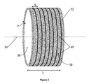
- the sleeve 32 is shown in more detail in Figure 3 .
- the sleeve 32 is a cylinder that is symmetrical about an axis 34 and has axial length L in the direction parallel to the axis 34.
- the axis 34 coincides with the axis about which the rotor 26 is symmetrical.
- these axes coincide with the axis of the stator 30 and the electrical machine 24 when in use.
- the axial length L of the sleeve 32 may be the same as the axial length of the rotor 26. Alternatively it may be shorter or longer than the rotor 26, provided that it is long enough to secure the magnets to the poles 28 and thus to the rotor 26.
- the sleeve 32 is a hollow cylinder. It therefore has radial thickness T which is the distance between the radially inner surface 36 and the radially outer surface 38 and which extends perpendicularly to the axis 34 of the sleeve 32.
- the sleeve 32 also includes a plurality of grooves 40. Each groove 40 extends circumferentially around the radially outer surface 38. The grooves 40 are axially spaced by spacing S so that the plurality of grooves 40 forms an axial array of circumferentially extending grooves 40.
- the spacing S may be constant between each adjacent pair of grooves 40 or may differ between pairs. This may be beneficial in managing any residual losses in the sleeve 32.
- each groove 40 may extend all the way around the circumference of the radially outer surface 38, that is through 360°.
- Each groove 40 is a trough or aperture into the radial thickness T of the sleeve 32 and may be rectangular in cross-section. It is formed of three walls, two parallel and one joining their ends. The fourth side of the rectangle is open and is flush with the radially outer surface 38 of the sleeve 32.
- the grooves 40 are aligned to be perpendicular to the eddy currents induced in the sleeve 32. Thus they usually extend radially.
- the cross-sectional form of the grooves 40 is shown in Figure 9 .
- the grooves 40 disrupt the eddy current patterns that form on a metallic sleeve 32 without grooves 40.
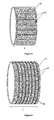
- a sleeve 32 without grooves 40 is shown in Figure 4 .
- the eddy current loops 42 have large magnitude, shown by thick lines, and extend across the full axial length L of the sleeve 32.
- the grooves 40 in the sleeve 32 cause the magnitude of the eddy currents 42 to reduce, as shown in Figure 5 by the thin lines, and/or the axial length of the eddy current loops 42 to reduce to cover only the axial distance between adjacent grooves 40, as shown in Figure 6.
- Figure 6 also shows that the magnitude of the eddy current loops 42 has reduced.
- the reduction in eddy currents consequently reduces the electrical power losses in the sleeve 32 because power is the product of current squared and resistance and so power loss is proportional to eddy current squared.
- One or more of the grooves 40 may have lesser circumferential extent. For example, one or more of the grooves 40 may extend through only 60°. Each of the plurality of grooves 40 may extend through between 60° and 360°. Different ones of the plurality of grooves 40 may have different angular extent to others of the plurality of grooves 40. For example, one groove 40 may extend through 60° but a groove 40 that is axially adjacent to it may extend through 120°.
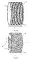
- Figure 7 is substantially the same as Figure 3 .
- the grooves 40 extend circumferentially around the radially inner surface 36.
- Figure 8 shows grooves 40 extending circumferentially on the radially inner surface 36 and on the radially outer surface 38.
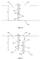
- Figure 9 is a cross section through the sleeve 32, in a radial plane.
- One of the grooves 40 can be seen extending from the radially outer surface 38 of the sleeve 32.
- the groove 40 is rectangular in cross-section. Although drawn with a straight end 44, distal to the surface 38 from which it extends, it may instead have a radiused end 44. The shape of the end 44 is dependent on the manner of forming the groove 40.
- the groove 40 has radial depth D which is the length between the radially outer surface 38 of the sleeve 32 and the distal end 44 of the groove 40.
- the groove 40 also has axial width W. This is the length of the discontinuity, in the axial direction, in the radially outer surface 38 as a result of the groove 40.
- the part of the sleeve 32 between the end 44 of the groove 40 and the other, radially inner, surface 36 is a bridge 46.
- the depth B of the bridge 46, in the radial direction, plus the radial depth D of the groove 40 is equal to the radial thickness T of the sleeve 32.
- the sleeve 32 is formed of metal or a metal alloy.
- the sleeve 32 therefore has electrical resistance R equal to the axial length multiplied by the electrical resistivity p divided by the cross-sectional area.
- the resistance R of the sleeve 32 locally to each groove 40 is increased because the cross-sectional area is decreased.
- the equivalent cross-sectional area for a portion of the sleeve 32 without a groove 40 is the width W multiplied by the radial thickness T of the sleeve 32.
- the cross-sectional area for the sleeve 32 where a groove 40 is provided is only the width W multiplied by the bridge depth D, which is considerably smaller than the radial thickness T of the sleeve 32.
- the reduction in local cross-sectional area also reduces the electrical power losses in the sleeve 32 because power is the product of current squared and resistance and so power loss is proportional to the resistance R of the sleeve 32.
- the sleeve 32 has an electrical skin depth ⁇ which is dependent on the electrical conductivity ⁇ of the sleeve 32, the relative magnetic permeability ⁇ r of the sleeve 32, the permeability of free space ⁇ o and the excitation frequency f of the induced eddy currents.
- the electrical skin depth ⁇ may be larger or smaller than the radial thickness T of the sleeve 32 since it depends on material properties rather than physical dimensions.
- the eddy currents are limited by the resistance R.
- the bridge depth B is set to one-third of the radial thickness T, so that the radial depth D of the groove 40 is two-thirds of the radial thickness T of the sleeve 32.
- the electrical skin depth ⁇ is smaller than the radial thickness T of the sleeve 32 the eddy currents are inductance limited.
- the radial depth D of the groove 40 is governed by setting the bridge depth B to be at least one-third of the electrical skin depth ⁇ .
- Figure 10 there are two grooves 40, one of which extends from the radially inner surface 36 and one of which extends from the radially outer surface 38.
- the bridge 46 is located radially between the ends 44 of the grooves 40 rather than being adjacent to one of the surfaces 36, 38.
- the grooves 40 may have the same radial depth D as each other or may have different radial depths D.
- the radial thickness T of the sleeve 32 is equal to the sum of the radial depths D of the two grooves 40 and the bridge depth B.
- Figure 11 illustrates a pair of axially adjacent grooves 40 in a sleeve 32.
- One of the grooves 40 drawn on the left of the figure, extends from the radially outer surface 38 whilst the other of the grooves 40, drawn on the right of the figure, extends from the radially inner surface 36.
- the width W of each groove 40 may be the same as the other groove 40 or the widths W may differ.
- the grooves 40 are spaced apart axially by offset O.
- the offset O may be greater than the axial width W of either of the grooves 40.
- the offset O is less than the spacing S between adjacent grooves 40 extending from the same one of the surfaces 36, 38.
- Each of the grooves 40 has sufficient radial depth D so that its distal end 44 overlaps radially with the distal end 44 of the other groove 40.
- this arrangement ensures that no portion of the sleeve 32 offers a straight path in an axial direction through which eddy currents can flow. Thus it guarantees that the eddy currents will follow a tortuous path, and therefore be reduced, whilst not compromising the mechanical integrity of the sleeve 32.
- a combination of axially aligned and axially offset grooves 40 may be provided on a sleeve 32 having grooves 40 extending from both the radially inner and radially outer surfaces 36, 38.
- Figure 12 illustrates a sleeve 32 having grooves 40 in its radially outer surface 38.
- the specific features are equally applicable to grooves 40 in the radially inner surface 36 of the sleeve 32 or to grooves 40 being provided in both surfaces 36, 38, whether or not those grooves 40 are axially aligned or include an offset O.
- the grooves 40 at least some of the axial positions the grooves extend through less than 360°. For example there may be a single groove 40 at each axial position which extends only a few degrees less than 360° so that a circumferential bridge 48 is left between the circumferential ends 50 of the groove 40. Alternatively there may be two grooves 40 from the radially outer surface 38 at a given axial alignment.
- the grooves 40 may extend by an equal amount or be of unequal circumferential lengths. For example, each groove 40 may extend less than 180° and be the same circumferential length so that there are two circumferential bridges 48 diametrically opposed around the surface 38.
- the grooves 40 may be fully circumferential, extending 360°. Alternatively they may also be shorter or there may be a pair of axially aligned grooves 40 extending from the radially outer surface 38. In these cases the grooves 40 are arranged so that the circumferential bridges 48 are circumferentially offset from the adjacent circumferential bridges 48. Advantageously this prevents there being a long axial path available for eddy currents.
- circumferential bridge 48 there may be one circumferential bridge 48 for each axial position of grooves 40.
- Axially adjacent circumferential bridges 48 are offset by approximately 180°.
- adjacent circumferential bridges are offset by approximately 60°.
- circumferential bridge 48 there may be more than one circumferential bridge 48 for each axial position of the grooves 40.
- Circumferential bridges 48 in adjacent axial positions are then offset by 90°. Different circumferential offsets are also envisaged, for example within the range 30° to 180° in either the clockwise sense or the anticlockwise sense.
- circumferential offsets between circumferentially adjacent bridges 48 may be different.
- circumferential offset in one direction may be 120° and the circumferential offset in the other direction may be 240°.
- Each groove 40 extends through at least 60°. Advantageously this ensures there is a sufficient effect on the electrical power losses.
- the sleeve 32 has greater mechanical integrity than the stack of washers known from US 8 698 367 . It is therefore easier to fit to the poles 28 of a rotor 26, for example by heat shrinking. Stress concentration on the sleeve 32 is also low due to the bridge 46 portions.
- a method of fabricating the sleeve 32 may comprise forming a hollow cylindrical sleeve 32 and then machining or cutting axially spaced, circumferentially extending grooves 40 into one or both of its radial surfaces 36, 38.
- the machining or cutting may be performed by water jet machining.
- this does not create stress points at the circumferential ends 50 of the grooves 40.
- the grooves 40 may be machined or cut by laser.
- the sleeve 32 protects the environment in which the electrical machine 24 operates.
- the sleeve 32 is also applicable in an electrical machine 24 in which the stator 30 is inside the rotor 26.
- the sleeve 32 surrounds the rotor 26 and acts to retain the electrical coil or coils against the centrifugal force.
- the sleeve 32 has application for any electrical machine 24 which experiences a high rim speed. Such high speed electrical machines 24 are used in automotive, kinetic energy recovery systems (KERS) for Formula 1 and other vehicles, diesel engines, and fly wheel energy storage. The sleeve 32 also finds application in direct drive applications with large diameter, such as marine gas turbine engines, wind turbines and tidal turbines.
- KERS kinetic energy recovery systems
Landscapes
- Engineering & Computer Science (AREA)
- Power Engineering (AREA)
- Manufacturing & Machinery (AREA)
- Iron Core Of Rotating Electric Machines (AREA)
- Permanent Field Magnets Of Synchronous Machinery (AREA)
Abstract
Description
- The present disclosure concerns a sleeve for retaining magnets around a rotor of an electrical machine. It also concerns a rotor comprising such a sleeve and an electrical machine comprising such a rotor.
- An electrical machine comprises a rotor and a stator, one surrounding the other. In a permanent magnet electrical machine a plurality of magnets are provided as a circumferential array around the rotor. In order to hold the magnets onto the rotor it is necessary to provide a sleeve, such as one or more cylindrical bands that can be heat shrunk onto the magnets and rotor.
- For an electrical machine operating at low speed and temperature it is possible to use carbon fibres wrapped around the magnets and rotor to retain the magnets in place. However, at higher speed and/or higher temperatures such fibres are not suitable and a metal or metal alloy sleeve is used. For example a hollow cylinder made of metal or metal alloy can be used.
- One problem with such metallic sleeves is that large eddy currents are induced which loop through the full axial extent of the sleeve. This causes significant power losses in the electrical machine. Consequently there may be detrimental effects on an associated cooling system, localised hotspots in the electrical machine and/or lower efficiency in the electrical machine.
-
US 8 698 367 teaches a retention device comprising a plurality of metallic washers which are stacked axially to give a segmented sleeve. The eddy currents thus do not cross from one washer to the next. One problem with this arrangement is that it is very difficult to accurately align the washers axially so that fitting is difficult and slow. Manufacture and stacking of many washers is also relatively costly. - According to a first aspect of the invention there is provided a sleeve for retaining magnets around a rotor of an electrical machine; the sleeve being cylindrical and hollow, having axial length and having radial thickness between its inner surface and outer surface; the sleeve defining a plurality of axially spaced, circumferentially extending grooves, each groove having radial depth less than the radial thickness of the sleeve.
- Advantageously the sleeve reduces electrical losses. Advantageously the sleeve may be made of a metal and thus be suitable for a high speed electrical machine. Advantageously the sleeve has mechanical integrity because it is a single continuous cylinder.
- The sleeve may comprise a radial bridge which is the difference between the radial thickness of the sleeve and the radial depth of each groove. The bridge may be greater than or equal to 1/3 (one-third) of the electrical skin depth of the sleeve. This bridge depth is appropriate where the eddy currents are inductance limited. The radial depth of each bridge may be equal to 1/3 (one-third) of the radial thickness of the sleeve. This bridge depth is appropriate where the eddy currents are resistance limited and so the electrical skin depth is greater than the radial thickness of the sleeve. Advantageously the bridge depth constraints act to minimise power losses in the sleeve due to eddy currents and electrical resistance.
- All the grooves may have the same radial depth. Alternatively some or all of the grooves may have different radial depths to others of the grooves.
- Each groove may extend circumferentially through less than 360°. Advantageously circumferential bridges are formed between circumferentially adjacent ends of the grooves which add mechanical strength to the sleeve. Each groove may extend circumferentially through at least 60°. Advantageously this ensures that there is a sufficient reduction in eddy currents due to the grooves.
- A circumferential bridge may be defined between circumferential ends of one or two circumferentially aligned grooves. Axially adjacent circumferential bridges may be circumferentially offset. Advantageously this offers a more tortuous path for eddy currents to traverse. Two or more circumferential bridges may be axially aligned and circumferentially spaced. Axially aligned grooves may have equal circumferential extent. Thus the associated circumferential bridges may be equi-angularly spaced. Alternatively the circumferential bridges between axially aligned grooves may be unequally spaced around the circumference of the sleeve.
- The grooves may extend from the outer surface of the sleeve. Alternatively or additionally the grooves may extend from the inner surface of the sleeve.
- A first plurality of grooves may extend from the outer surface of the sleeve and a second plurality of grooves may extend from the inner surface of the sleeve. Advantageously it may be easier to machine grooves axially close together if alternate grooves extend from the inner and outer surfaces of the sleeve.
- The combined radial depth of grooves extending from the outer and inner surfaces of the sleeve may be less than the radial thickness of the sleeve. Alternatively where a groove extending from the inner surface of the sleeve is axially offset from any groove extending from the outer surface of the sleeve the combined radial depth of the grooves may be greater than the radial thickness of the sleeve. In this case the ends of the grooves overlap radially but are spaced axially.
- At least one groove from the first plurality of grooves may be axially aligned with at least one groove from the second plurality of grooves. The combined radial depth of axially aligned grooves extending from the outer and inner surfaces of the sleeve may be less than the radial thickness of the sleeve.
- The sleeve may be metal. Advantageously the sleeve is suitable for use in a high speed electrical machine.
- Also an electrical machine rotor comprising:
- a rotor shaft;
- a plurality of permanent magnets located in a circumferential array around the surface of the rotor shaft; and
- a sleeve as described, the sleeve being affixed radially outside the magnets to retain them to the rotor shaft.
- Advantageously such an electrical machine rotor is suitable for a high speed and/or large diameter electrical machine in which the permanent magnets are subjected to large centrifugal forces.
- Also an electrical machine rotor comprising:
- a rotor shaft;
- at least one electrical coil located on the surface of the rotor shaft; and
- a sleeve as described, the sleeve being affixed radially outside the electrical coil to retain it to the rotor shaft.
- Advantageously such an electrical machine rotor is suitable for a high speed and/or large diameter electrical machine in which the electrical coil or coils is/are subjected to large centrifugal forces.
- Also an electrical machine comprising an electrical machine rotor as described.
- Also a method of fabricating a sleeve as described, the method comprising steps to:
- form a cylindrical sleeve; and
- cut axially spaced, circumferentially extending grooves into one or both radial surfaces of the sleeve.
- The step to cut the grooves may be performed by water jet machining. Alternatively the step to cut the grooves may be performed by laser cutting.
- The skilled person will appreciate that except where mutually exclusive, a feature described in relation to any one of the above aspects of the invention may be applied mutatis mutandis to any other aspect of the invention.
- Embodiments of the invention will now be described by way of example only, with reference to the Figures, in which:
-
Figure 1 is a sectional side view of a gas turbine engine; -
Figure 2 is a schematic cross-section of an electrical machine; -
Figure 3 is a perspective schematic drawing of a sleeve with grooves; -
Figure 4 is a perspective schematic drawing of a sleeve without grooves and illustrates eddy current paths; -
Figure 5 is a perspective schematic drawing of a sleeve with grooves and illustrates eddy current paths; -
Figure 6 is a perspective schematic drawing of a sleeve with grooves and illustrates eddy current paths; -
Figure 7 is perspective schematic drawing of a sleeve with grooves; -
Figure 8 is perspective schematic drawing of a sleeve with grooves; -
Figure 9 is a schematic cross-section through a groove; -
Figure 10 is a schematic cross-section through a pair of axially aligned grooves; -
Figure 11 is a schematic cross-section through a pair of axially spaced grooves; -
Figure 12 is perspective schematic drawing of a sleeve with grooves; -
Figure 13 is perspective schematic drawing of a sleeve with grooves. - With reference to
Figure 1 , a gas turbine engine is generally indicated at 10, having a principal androtational axis 11. Theengine 10 comprises, in axial flow series, anair intake 12, apropulsive fan 13, anintermediate pressure compressor 14, a high-pressure compressor 15,combustion equipment 16, a high-pressure turbine 17, andintermediate pressure turbine 18, a low-pressure turbine 19 and anexhaust nozzle 20. Anacelle 21 generally surrounds theengine 10 and defines both theintake 12 and theexhaust nozzle 20. - The
gas turbine engine 10 works in the conventional manner so that air entering theintake 12 is accelerated by thefan 13 to produce two air flows: a first air flow into theintermediate pressure compressor 14 and a second air flow which passes through a bypass duct 22 to provide propulsive thrust. Theintermediate pressure compressor 14 compresses the air flow directed into it before delivering that air to thehigh pressure compressor 15 where further compression takes place. - The compressed air exhausted from the high-
pressure compressor 15 is directed into thecombustion equipment 16 where it is mixed with fuel and the mixture combusted. The resultant hot combustion products then expand through, and thereby drive the high, intermediate and low-pressure turbines nozzle 20 to provide additional propulsive thrust. The high 17, intermediate 18 and low 19 pressure turbines drive respectively thehigh pressure compressor 15,intermediate pressure compressor 14 andfan 13, each by suitable interconnecting shaft. - Such a
gas turbine engine 10 may be used to power an aircraft, to power a ship or in other marine applications, or may form part of a land or sea based power plant. - An
electrical machine 24 may be associated with, coupled to or be driven by such agas turbine engine 10. Anelectrical machine 24 may be mounted to the outside of agas turbine engine 10, either directly or through an auxiliary gearbox. Alternatively anelectrical machine 24 may be located within agas turbine engine 10, for example by being directly mounted to one of the interconnecting shafts. - Such an
electrical machine 24 may be constituted as a generator to provide electrical power to thegas turbine engine 10 or to the aircraft, ship or plant which is powered by thegas turbine engine 10. Alternatively or additionally anelectrical machine 24 may be constituted as a motor to provide electrical power to start agas turbine engine 10, or to power engine accessories such as oil or fuel pumps. - An
electrical machine 24 is shown inFigure 2 . It comprises arotor 26 with a plurality ofpoles 28 at least partially provided by permanent magnets. Radially outside, and spaced from, thepoles 28 of therotor 26 is astator 30. Themagnets 28 are held firmly to therotor 26 by asleeve 32. Thesleeve 32 is a hollow and cylindrical. To be suitable for high speed, and high temperature, operation of theelectrical machine 24 thesleeve 32 is comprised of metal. For example, it may be formed from titanium, titanium alloy or a nickel-chromium alloy such as Inconel. - The
sleeve 32 is shown in more detail inFigure 3 . Thesleeve 32 is a cylinder that is symmetrical about anaxis 34 and has axial length L in the direction parallel to theaxis 34. When thesleeve 32 is mounted to therotor 26 theaxis 34 coincides with the axis about which therotor 26 is symmetrical. Similarly, these axes coincide with the axis of thestator 30 and theelectrical machine 24 when in use. The axial length L of thesleeve 32 may be the same as the axial length of therotor 26. Alternatively it may be shorter or longer than therotor 26, provided that it is long enough to secure the magnets to thepoles 28 and thus to therotor 26. - The
sleeve 32 is a hollow cylinder. It therefore has radial thickness T which is the distance between the radiallyinner surface 36 and the radiallyouter surface 38 and which extends perpendicularly to theaxis 34 of thesleeve 32. Thesleeve 32 also includes a plurality ofgrooves 40. Eachgroove 40 extends circumferentially around the radiallyouter surface 38. Thegrooves 40 are axially spaced by spacing S so that the plurality ofgrooves 40 forms an axial array of circumferentially extendinggrooves 40. The spacing S may be constant between each adjacent pair ofgrooves 40 or may differ between pairs. This may be beneficial in managing any residual losses in thesleeve 32. There is a relationship between the spacing S and the electrical losses in thesleeve 32 such that a smaller spacing S results in lower electrical losses. This is because there aremore grooves 40 for a given axial length of thesleeve 32. Eachgroove 40 may extend all the way around the circumference of the radiallyouter surface 38, that is through 360°. - Each
groove 40 is a trough or aperture into the radial thickness T of thesleeve 32 and may be rectangular in cross-section. It is formed of three walls, two parallel and one joining their ends. The fourth side of the rectangle is open and is flush with the radiallyouter surface 38 of thesleeve 32. Thegrooves 40 are aligned to be perpendicular to the eddy currents induced in thesleeve 32. Thus they usually extend radially. The cross-sectional form of thegrooves 40 is shown inFigure 9 . - Advantageously the
grooves 40 disrupt the eddy current patterns that form on ametallic sleeve 32 withoutgrooves 40. Asleeve 32 withoutgrooves 40 is shown inFigure 4 . Theeddy current loops 42 have large magnitude, shown by thick lines, and extend across the full axial length L of thesleeve 32. By contrast thegrooves 40 in thesleeve 32 cause the magnitude of theeddy currents 42 to reduce, as shown inFigure 5 by the thin lines, and/or the axial length of theeddy current loops 42 to reduce to cover only the axial distance betweenadjacent grooves 40, as shown inFigure 6. Figure 6 also shows that the magnitude of theeddy current loops 42 has reduced. The reduction in eddy currents consequently reduces the electrical power losses in thesleeve 32 because power is the product of current squared and resistance and so power loss is proportional to eddy current squared. - One or more of the
grooves 40 may have lesser circumferential extent. For example, one or more of thegrooves 40 may extend through only 60°. Each of the plurality ofgrooves 40 may extend through between 60° and 360°. Different ones of the plurality ofgrooves 40 may have different angular extent to others of the plurality ofgrooves 40. For example, onegroove 40 may extend through 60° but agroove 40 that is axially adjacent to it may extend through 120°. -
Figure 7 is substantially the same asFigure 3 . However, thegrooves 40 extend circumferentially around the radiallyinner surface 36.Figure 8 showsgrooves 40 extending circumferentially on the radiallyinner surface 36 and on the radiallyouter surface 38. -
Figure 9 is a cross section through thesleeve 32, in a radial plane. One of thegrooves 40 can be seen extending from the radiallyouter surface 38 of thesleeve 32. Thegroove 40 is rectangular in cross-section. Although drawn with astraight end 44, distal to thesurface 38 from which it extends, it may instead have aradiused end 44. The shape of theend 44 is dependent on the manner of forming thegroove 40. - The
groove 40 has radial depth D which is the length between the radiallyouter surface 38 of thesleeve 32 and thedistal end 44 of thegroove 40. Thegroove 40 also has axial width W. This is the length of the discontinuity, in the axial direction, in the radiallyouter surface 38 as a result of thegroove 40. - The part of the
sleeve 32 between theend 44 of thegroove 40 and the other, radially inner,surface 36 is abridge 46. The depth B of thebridge 46, in the radial direction, plus the radial depth D of thegroove 40 is equal to the radial thickness T of thesleeve 32. - The
sleeve 32 is formed of metal or a metal alloy. Thesleeve 32 therefore has electrical resistance R equal to the axial length multiplied by the electrical resistivity p divided by the cross-sectional area. The resistance R of thesleeve 32 locally to eachgroove 40 is increased because the cross-sectional area is decreased. The equivalent cross-sectional area for a portion of thesleeve 32 without agroove 40 is the width W multiplied by the radial thickness T of thesleeve 32. The cross-sectional area for thesleeve 32 where agroove 40 is provided is only the width W multiplied by the bridge depth D, which is considerably smaller than the radial thickness T of thesleeve 32. The reduction in local cross-sectional area also reduces the electrical power losses in thesleeve 32 because power is the product of current squared and resistance and so power loss is proportional to the resistance R of thesleeve 32. - The
sleeve 32 has an electrical skin depth δ which is dependent on the electrical conductivity σ of thesleeve 32, the relative magnetic permeability µr of thesleeve 32, the permeability of free space µo and the excitation frequency f of the induced eddy currents. The electrical conductivity σ and the relative magnetic permeability µr are each material properties of thesleeve 32; the permeability of free space µo is a physical constant, µo = 4π × 10-7 NA -2 . Specifically, the electrical skin depth δ is defined as
sleeve 32 since it depends on material properties rather than physical dimensions. - Where the electrical skin depth δ is larger than the radial thickness T of the
sleeve 32, the eddy currents are limited by the resistance R. In this case the bridge depth B is set to one-third of the radial thickness T, so that the radial depth D of thegroove 40 is two-thirds of the radial thickness T of thesleeve 32. On the other hand, where the electrical skin depth δ is smaller than the radial thickness T of thesleeve 32 the eddy currents are inductance limited. In this case the radial depth D of thegroove 40 is governed by setting the bridge depth B to be at least one-third of the electrical skin depth δ. Advantageously these constraints on the bridge depth B, and therefore on the radial depth D of thegrooves 40, act to minimise the power losses in thesleeve 32 due to eddy currents and electrical resistance R. - Other groove depths D may also be used, although the power losses in these cases will be reduced rather than minimised.
- The explanation of the dimensions of the
groove 40 andbridge 46 given in respect toFigure 9 is applicable, mutatis mutandis, where thegroove 40 extends from the radiallyinner surface 36 instead of from the radiallyouter surface 38. - In
Figure 10 there are twogrooves 40, one of which extends from the radiallyinner surface 36 and one of which extends from the radiallyouter surface 38. Thus thebridge 46 is located radially between theends 44 of thegrooves 40 rather than being adjacent to one of thesurfaces grooves 40 may have the same radial depth D as each other or may have different radial depths D. The radial thickness T of thesleeve 32 is equal to the sum of the radial depths D of the twogrooves 40 and the bridge depth B. -
Figure 11 illustrates a pair of axiallyadjacent grooves 40 in asleeve 32. One of thegrooves 40, drawn on the left of the figure, extends from the radiallyouter surface 38 whilst the other of thegrooves 40, drawn on the right of the figure, extends from the radiallyinner surface 36. The width W of eachgroove 40 may be the same as theother groove 40 or the widths W may differ. Thegrooves 40 are spaced apart axially by offset O. The offset O may be greater than the axial width W of either of thegrooves 40. The offset O is less than the spacing S betweenadjacent grooves 40 extending from the same one of thesurfaces grooves 40 has sufficient radial depth D so that itsdistal end 44 overlaps radially with thedistal end 44 of theother groove 40. Advantageously this arrangement ensures that no portion of thesleeve 32 offers a straight path in an axial direction through which eddy currents can flow. Thus it guarantees that the eddy currents will follow a tortuous path, and therefore be reduced, whilst not compromising the mechanical integrity of thesleeve 32. - A combination of axially aligned and axially offset
grooves 40 may be provided on asleeve 32 havinggrooves 40 extending from both the radially inner and radiallyouter surfaces -
Figure 12 illustrates asleeve 32 havinggrooves 40 in its radiallyouter surface 38. However, the specific features are equally applicable togrooves 40 in the radiallyinner surface 36 of thesleeve 32 or togrooves 40 being provided in bothsurfaces grooves 40 are axially aligned or include an offset O. - The
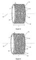
grooves 40 at least some of the axial positions the grooves extend through less than 360°. For example there may be asingle groove 40 at each axial position which extends only a few degrees less than 360° so that acircumferential bridge 48 is left between the circumferential ends 50 of thegroove 40. Alternatively there may be twogrooves 40 from the radiallyouter surface 38 at a given axial alignment. Thegrooves 40 may extend by an equal amount or be of unequal circumferential lengths. For example, eachgroove 40 may extend less than 180° and be the same circumferential length so that there are twocircumferential bridges 48 diametrically opposed around thesurface 38. - At axial positions adjacent to circumferentially
shorter grooves 40, thegrooves 40 may be fully circumferential, extending 360°. Alternatively they may also be shorter or there may be a pair of axially alignedgrooves 40 extending from the radiallyouter surface 38. In these cases thegrooves 40 are arranged so that thecircumferential bridges 48 are circumferentially offset from the adjacent circumferential bridges 48. Advantageously this prevents there being a long axial path available for eddy currents. - In
Figure 12 there may be onecircumferential bridge 48 for each axial position ofgrooves 40. Axially adjacentcircumferential bridges 48 are offset by approximately 180°. InFigure 13 adjacent circumferential bridges are offset by approximately 60°. - In
Figure 13 there may be more than onecircumferential bridge 48 for each axial position of thegrooves 40. For example there may be twocircumferential bridges 48 at each axial position of thegrooves 40 which are offset by 180°, or there may be threecircumferential bridges 48 at each axial position of thegrooves 40, with each pair of thecircumferential bridges 48 offset by 120°. InFigure 12 there may be twocircumferential bridges 48, spaced 180° apart, for each axial position of thegrooves 40.Circumferential bridges 48 in adjacent axial positions are then offset by 90°. Different circumferential offsets are also envisaged, for example within therange 30° to 180° in either the clockwise sense or the anticlockwise sense. Where there is more than onecircumferential bridge 48 at one axial alignment, the circumferential offsets between circumferentiallyadjacent bridges 48 may be different. Thus with two axially alignedcircumferential bridges 48 the circumferential offset in one direction may be 120° and the circumferential offset in the other direction may be 240°. - Each
groove 40 extends through at least 60°. Advantageously this ensures there is a sufficient effect on the electrical power losses. - The
sleeve 32 has greater mechanical integrity than the stack of washers known fromUS 8 698 367 . It is therefore easier to fit to thepoles 28 of arotor 26, for example by heat shrinking. Stress concentration on thesleeve 32 is also low due to thebridge 46 portions. - A method of fabricating the
sleeve 32 may comprise forming a hollowcylindrical sleeve 32 and then machining or cutting axially spaced, circumferentially extendinggrooves 40 into one or both of itsradial surfaces grooves 40. Alternatively thegrooves 40 may be machined or cut by laser. - Advantageously the
sleeve 32 protects the environment in which theelectrical machine 24 operates. - The
sleeve 32 is also applicable in anelectrical machine 24 in which thestator 30 is inside therotor 26. In this case thesleeve 32 surrounds therotor 26 and acts to retain the electrical coil or coils against the centrifugal force. - The
sleeve 32 has application for anyelectrical machine 24 which experiences a high rim speed. Such high speedelectrical machines 24 are used in automotive, kinetic energy recovery systems (KERS) forFormula 1 and other vehicles, diesel engines, and fly wheel energy storage. Thesleeve 32 also finds application in direct drive applications with large diameter, such as marine gas turbine engines, wind turbines and tidal turbines. - It will be understood that the invention is not limited to the embodiments above-described and various modifications and improvements can be made without departing from the concepts described herein. Except where mutually exclusive, any of the features may be employed separately or in combination with any other features and the disclosure extends to and includes all combinations and sub-combinations of one or more features described herein.
Claims (15)
- A sleeve (32) for retaining magnets (28) around a rotor (26) of an electrical machine (24); the sleeve (32) being cylindrical and hollow, having axial length (L) and having radial thickness (T) between its inner surface (36) and outer surface (38); the sleeve (32) defining a plurality of axially spaced, circumferentially extending grooves (40), each groove (40) having radial depth (D) less than the radial thickness (T) of the sleeve (32) wherein the grooves (40) extend from the inner surface (36) of the sleeve (32).
- A sleeve (32) as claimed in claim 1 wherein a radial bridge (46) is the difference between the radial thickness (T) of the sleeve (32) and the radial depth (D) of each groove (40); the bridge (46) being greater than or equal to 1/3 of the electrical skin depth (δ) of the sleeve (32).
- A sleeve (32) as claimed in claim 2 wherein the radial depth (D) of each bridge (46) is equal to 1/3 of the radial thickness (T) of the sleeve (32) where the electrical skin depth (δ) is greater than the radial thickness (T) of the sleeve (32).
- A sleeve (32) as claimed in any preceding claim wherein each groove (40) extends circumferentially through less than 360° and wherein each groove (40) extends circumferentially through at least 60°.
- A sleeve (32) as claimed in claim 4 wherein a circumferential bridge (48) is defined between circumferential ends (50) of one or two circumferentially aligned grooves (40), and wherein axially adjacent circumferential bridges (48) are circumferentially offset.
- A sleeve (32) as claimed in claim 5 wherein two or more circumferential bridges (48) are axially aligned and circumferentially spaced.
- A sleeve (32) as claimed in claim 6 wherein the axially aligned grooves (40) have equal circumferential extent.
- A sleeve (32) as claimed in any preceding claim wherein a first plurality of grooves (40) extend from the outer surface (38) of the sleeve (32) and a second plurality of grooves (40) extend from the inner surface (36) of the sleeve (32).
- A sleeve (32) as claimed in claim 8 wherein at least one groove (40) from the first plurality is axially aligned with at least one groove (40) from the second plurality.
- A sleeve (32) as claimed in claim 8 or claim 9 wherein the combined radial depth (D) is less than the radial thickness (T) of the sleeve (32).
- An electrical machine rotor (26) comprising:• a rotor shaft;• a plurality of permanent magnets (28) located in a circumferential array around the surface of the rotor shaft; and• a sleeve (32) as claimed in any of claims 1 to 10, the sleeve (32) being affixed radially outside the magnets (28) to retain them to the rotor shaft.
- An electrical machine rotor (26) comprising:• a rotor shaft;• at least one electrical coil located on the surface of the rotor shaft; and• a sleeve (32) as claimed in any of claims 1 to 10, the sleeve (32) being affixed radially outside the electrical coil to retain it to the rotor shaft.
- An electrical machine (24) comprising an electrical machine rotor (26) as claimed in claim 11 or 12.
- A method of fabricating a sleeve (32) as claimed in any of claims 1 to 10, the method comprising steps to:• form a cylindrical sleeve (32); and• cut axially spaced, circumferentially extending grooves (40) into one or both radial surfaces of the sleeve (32).
- A method as claimed in claim 14 wherein the step to cut the grooves (40) is performed by water jet machining.
Applications Claiming Priority (1)
| Application Number | Priority Date | Filing Date | Title |
|---|---|---|---|
| GB201504283A GB201504283D0 (en) | 2015-03-13 | 2015-03-13 | Sleeve for an electrical machine |
Publications (3)
| Publication Number | Publication Date |
|---|---|
| EP3068019A2 true EP3068019A2 (en) | 2016-09-14 |
| EP3068019A3 EP3068019A3 (en) | 2016-12-07 |
| EP3068019B1 EP3068019B1 (en) | 2023-05-24 |
Family
ID=53016089
Family Applications (1)
| Application Number | Title | Priority Date | Filing Date |
|---|---|---|---|
| EP16156359.8A Active EP3068019B1 (en) | 2015-03-13 | 2016-02-18 | Permanent magnet electrical machine and gas turbine engine comprising a permanent magnet electrical machine |
Country Status (3)
| Country | Link |
|---|---|
| US (1) | US10122228B2 (en) |
| EP (1) | EP3068019B1 (en) |
| GB (1) | GB201504283D0 (en) |
Cited By (2)
| Publication number | Priority date | Publication date | Assignee | Title |
|---|---|---|---|---|
| EP3451499A1 (en) * | 2017-09-05 | 2019-03-06 | Rolls-Royce PLC | Electrical machine rotor |
| EP3490109A1 (en) * | 2017-11-23 | 2019-05-29 | Siemens Gamesa Renewable Energy A/S | Permanent magnet support of a permanent magnet generator |
Families Citing this family (5)
| Publication number | Priority date | Publication date | Assignee | Title |
|---|---|---|---|---|
| GB201504283D0 (en) * | 2015-03-13 | 2015-04-29 | Rolls Royce Plc | Sleeve for an electrical machine |
| JP7293701B2 (en) * | 2019-02-08 | 2023-06-20 | 株式会社デンソー | Rotating electric machine |
| CN113014013B (en) * | 2019-12-20 | 2023-06-09 | 新疆金风科技股份有限公司 | Rotor brackets, rotors, motors and wind turbines |
| US12525829B2 (en) | 2023-09-19 | 2026-01-13 | Rolls-Royce Corporation | Composite stator sleeve for electric machine |
| US20250293560A1 (en) * | 2023-09-29 | 2025-09-18 | Rolls-Royce North American Technologies, Inc. | Magnet retention in exterior rotor electric machines |
Family Cites Families (19)
| Publication number | Priority date | Publication date | Assignee | Title |
|---|---|---|---|---|
| US4117360A (en) * | 1977-04-15 | 1978-09-26 | General Electric Company | Self-supporting amortisseur cage for high-speed synchronous machine solid rotor |
| US4531071A (en) * | 1983-12-12 | 1985-07-23 | Sundstrand Corporation | Rotor assembly |
| FR2565044B1 (en) * | 1984-05-23 | 1987-08-28 | Labinal | IMPROVEMENT IN ROTARY MAGNET ROTOR MACHINES |
| JPH0816303A (en) | 1994-06-30 | 1996-01-19 | Pentel Kk | Signal input pen |
| JP3369024B2 (en) * | 1995-04-14 | 2003-01-20 | 松下電器産業株式会社 | Permanent magnet rotor and its manufacturing method |
| BR9504941A (en) * | 1995-11-13 | 1997-10-21 | Brasil Compressores Sa | Rotor cover for electric motor |
| JPH1080081A (en) | 1996-09-02 | 1998-03-24 | Matsushita Electric Ind Co Ltd | Permanent magnet rotor |
| US6509664B2 (en) * | 2000-01-13 | 2003-01-21 | General Electric Company | Hybrid synchronous machines comprising permanent magnets and excitation windings in cylindrical element slots |
| WO2002078154A1 (en) * | 2001-03-24 | 2002-10-03 | Lg Electronics Inc. | Mover assembly of reciprocating motor and fabrication method thereof |
| JP2007074776A (en) * | 2005-09-05 | 2007-03-22 | Kokusan Denki Co Ltd | Rotating electric machine |
| US20080238234A1 (en) * | 2007-03-27 | 2008-10-02 | Hamilton Sundstrand Corporation | Segmented permanent magnet rotor for high speed synchronous machines |
| CL2009000917A1 (en) * | 2008-04-17 | 2010-07-02 | K Sortore Christopher | A machine comprising a rotor with a plurality of rare earth permanent magnets, retained in the rotor by means of a cylindrical bushing, the bushing is retained by means of a band having a stacked plurality of washer laminations, each lamination being isolated electrically. |
| US20100019598A1 (en) * | 2008-07-28 | 2010-01-28 | Direct Drive Systems, Inc. | Rotor for an electric machine |
| CN102549885A (en) * | 2009-09-29 | 2012-07-04 | 西门子公司 | Rotor |
| US9225205B2 (en) | 2011-08-18 | 2015-12-29 | Glassy Metal Technologies Ltd. | Method of constructing core with tapered pole pieces and low-loss electrical rotating machine with said core |
| CN202231514U (en) * | 2011-09-06 | 2012-05-23 | 徐州工业职业技术学院 | Protective device of magnetoelectric machine rotor |
| CN102361385A (en) * | 2011-10-13 | 2012-02-22 | 中国船舶重工集团公司第七○五研究所 | Brushless direct current motor |
| JP6087584B2 (en) | 2012-10-31 | 2017-03-01 | 東芝産業機器システム株式会社 | Rotor for surface magnet-attached rotary electric machine and method for manufacturing the same |
| GB201504283D0 (en) * | 2015-03-13 | 2015-04-29 | Rolls Royce Plc | Sleeve for an electrical machine |
-
2015
- 2015-03-13 GB GB201504283A patent/GB201504283D0/en not_active Ceased
-
2016
- 2016-02-18 EP EP16156359.8A patent/EP3068019B1/en active Active
- 2016-02-18 US US15/047,094 patent/US10122228B2/en active Active
Non-Patent Citations (1)
| Title |
|---|
| None * |
Cited By (5)
| Publication number | Priority date | Publication date | Assignee | Title |
|---|---|---|---|---|
| EP3451499A1 (en) * | 2017-09-05 | 2019-03-06 | Rolls-Royce PLC | Electrical machine rotor |
| US11025112B2 (en) | 2017-09-05 | 2021-06-01 | Rolls-Royce Plc | Electrical machine rotor |
| EP3490109A1 (en) * | 2017-11-23 | 2019-05-29 | Siemens Gamesa Renewable Energy A/S | Permanent magnet support of a permanent magnet generator |
| CN109831044A (en) * | 2017-11-23 | 2019-05-31 | 西门子歌美飒可再生能源公司 | Permanent magnet supports for permanent magnet generators |
| CN109831044B (en) * | 2017-11-23 | 2022-05-31 | 西门子歌美飒可再生能源公司 | Permanent magnet support for a permanent magnet generator |
Also Published As
| Publication number | Publication date |
|---|---|
| US20160268854A1 (en) | 2016-09-15 |
| US10122228B2 (en) | 2018-11-06 |
| GB201504283D0 (en) | 2015-04-29 |
| EP3068019B1 (en) | 2023-05-24 |
| EP3068019A3 (en) | 2016-12-07 |
Similar Documents
| Publication | Publication Date | Title |
|---|---|---|
| EP3068019B1 (en) | Permanent magnet electrical machine and gas turbine engine comprising a permanent magnet electrical machine | |
| US10381889B2 (en) | Permanent magnet machine with segmented sleeve for magnets | |
| US11387724B2 (en) | Dual-rotor electric machine | |
| EP3680488B1 (en) | Electric machine having permanent magnets embedded in blades | |
| KR102255948B1 (en) | Decoupler assemblies for engine starter | |
| US7603864B2 (en) | Blade tip electric machine | |
| EP3451499B1 (en) | Electrical machine rotor | |
| US11788428B2 (en) | Integrated hybrid propulsion system | |
| EP2896791A1 (en) | Mistuned airfoil assemblies | |
| US11063494B2 (en) | Electrical machine apparatus | |
| EP4115059B1 (en) | A power generation system | |
| DE112013004991B4 (en) | Method for connecting bearing housing segments of a turbocharger comprising an electric motor | |
| US20190097479A1 (en) | Permanent magnet electrical machine | |
| JP6561047B2 (en) | High-speed switched reluctance motor for turbochargers | |
| EP3523506B1 (en) | Method of assembling an electrified turbocharger | |
| US20220302779A1 (en) | Rotor assembly | |
| CN114765392A (en) | Electric machine with a receiving belt | |
| US20120299435A1 (en) | Method for applying a retaining system above a rotor core of an electric machine and rotor assembly | |
| US20190089211A1 (en) | Electric machine comprising a stator provided with an inner tubular sleeve | |
| US10720804B2 (en) | Permanent magnet machine with segmented sleeve for magnets | |
| US20250112523A1 (en) | Magnet retention in exterior rotor electric machines | |
| US20250246956A1 (en) | Magnet retention in exterior rotor electric machines | |
| EP3758195A1 (en) | Permanent magnet machine | |
| US11870305B2 (en) | System and method for reduced rotor losses | |
| Akcay et al. | Design and development of an axial magnetic coupling for reliable aircraft power generation |
Legal Events
| Date | Code | Title | Description |
|---|---|---|---|
| PUAI | Public reference made under article 153(3) epc to a published international application that has entered the european phase |
Free format text: ORIGINAL CODE: 0009012 |
|
| AK | Designated contracting states |
Kind code of ref document: A2 Designated state(s): AL AT BE BG CH CY CZ DE DK EE ES FI FR GB GR HR HU IE IS IT LI LT LU LV MC MK MT NL NO PL PT RO RS SE SI SK SM TR |
|
| AX | Request for extension of the european patent |
Extension state: BA ME |
|
| PUAL | Search report despatched |
Free format text: ORIGINAL CODE: 0009013 |
|
| AK | Designated contracting states |
Kind code of ref document: A3 Designated state(s): AL AT BE BG CH CY CZ DE DK EE ES FI FR GB GR HR HU IE IS IT LI LT LU LV MC MK MT NL NO PL PT RO RS SE SI SK SM TR |
|
| AX | Request for extension of the european patent |
Extension state: BA ME |
|
| RIC1 | Information provided on ipc code assigned before grant |
Ipc: H02K 1/28 20060101AFI20161103BHEP |
|
| STAA | Information on the status of an ep patent application or granted ep patent |
Free format text: STATUS: REQUEST FOR EXAMINATION WAS MADE |
|
| 17P | Request for examination filed |
Effective date: 20170601 |
|
| RBV | Designated contracting states (corrected) |
Designated state(s): AL AT BE BG CH CY CZ DE DK EE ES FI FR GB GR HR HU IE IS IT LI LT LU LV MC MK MT NL NO PL PT RO RS SE SI SK SM TR |
|
| STAA | Information on the status of an ep patent application or granted ep patent |
Free format text: STATUS: EXAMINATION IS IN PROGRESS |
|
| 17Q | First examination report despatched |
Effective date: 20190426 |
|
| RAP1 | Party data changed (applicant data changed or rights of an application transferred) |
Owner name: ROLLS-ROYCE PLC |
|
| GRAP | Despatch of communication of intention to grant a patent |
Free format text: ORIGINAL CODE: EPIDOSNIGR1 |
|
| STAA | Information on the status of an ep patent application or granted ep patent |
Free format text: STATUS: GRANT OF PATENT IS INTENDED |
|
| GRAJ | Information related to disapproval of communication of intention to grant by the applicant or resumption of examination proceedings by the epo deleted |
Free format text: ORIGINAL CODE: EPIDOSDIGR1 |
|
| STAA | Information on the status of an ep patent application or granted ep patent |
Free format text: STATUS: EXAMINATION IS IN PROGRESS |
|
| INTG | Intention to grant announced |
Effective date: 20221222 |
|
| INTC | Intention to grant announced (deleted) | ||
| GRAP | Despatch of communication of intention to grant a patent |
Free format text: ORIGINAL CODE: EPIDOSNIGR1 |
|
| STAA | Information on the status of an ep patent application or granted ep patent |
Free format text: STATUS: GRANT OF PATENT IS INTENDED |
|
| INTG | Intention to grant announced |
Effective date: 20230301 |
|
| GRAS | Grant fee paid |
Free format text: ORIGINAL CODE: EPIDOSNIGR3 |
|
| GRAA | (expected) grant |
Free format text: ORIGINAL CODE: 0009210 |
|
| STAA | Information on the status of an ep patent application or granted ep patent |
Free format text: STATUS: THE PATENT HAS BEEN GRANTED |
|
| AK | Designated contracting states |
Kind code of ref document: B1 Designated state(s): AL AT BE BG CH CY CZ DE DK EE ES FI FR GB GR HR HU IE IS IT LI LT LU LV MC MK MT NL NO PL PT RO RS SE SI SK SM TR |
|
| REG | Reference to a national code |
Ref country code: GB Ref legal event code: FG4D |
|
| REG | Reference to a national code |
Ref country code: CH Ref legal event code: EP |
|
| REG | Reference to a national code |
Ref country code: DE Ref legal event code: R096 Ref document number: 602016079538 Country of ref document: DE |
|
| REG | Reference to a national code |
Ref country code: AT Ref legal event code: REF Ref document number: 1570161 Country of ref document: AT Kind code of ref document: T Effective date: 20230615 |
|
| REG | Reference to a national code |
Ref country code: IE Ref legal event code: FG4D |
|
| P01 | Opt-out of the competence of the unified patent court (upc) registered |
Effective date: 20230530 |
|
| REG | Reference to a national code |
Ref country code: LT Ref legal event code: MG9D |
|
| REG | Reference to a national code |
Ref country code: NL Ref legal event code: MP Effective date: 20230524 |
|
| REG | Reference to a national code |
Ref country code: AT Ref legal event code: MK05 Ref document number: 1570161 Country of ref document: AT Kind code of ref document: T Effective date: 20230524 |
|
| PG25 | Lapsed in a contracting state [announced via postgrant information from national office to epo] |
Ref country code: SE Free format text: LAPSE BECAUSE OF FAILURE TO SUBMIT A TRANSLATION OF THE DESCRIPTION OR TO PAY THE FEE WITHIN THE PRESCRIBED TIME-LIMIT Effective date: 20230524 Ref country code: PT Free format text: LAPSE BECAUSE OF FAILURE TO SUBMIT A TRANSLATION OF THE DESCRIPTION OR TO PAY THE FEE WITHIN THE PRESCRIBED TIME-LIMIT Effective date: 20230925 Ref country code: NO Free format text: LAPSE BECAUSE OF FAILURE TO SUBMIT A TRANSLATION OF THE DESCRIPTION OR TO PAY THE FEE WITHIN THE PRESCRIBED TIME-LIMIT Effective date: 20230824 Ref country code: NL Free format text: LAPSE BECAUSE OF FAILURE TO SUBMIT A TRANSLATION OF THE DESCRIPTION OR TO PAY THE FEE WITHIN THE PRESCRIBED TIME-LIMIT Effective date: 20230524 Ref country code: ES Free format text: LAPSE BECAUSE OF FAILURE TO SUBMIT A TRANSLATION OF THE DESCRIPTION OR TO PAY THE FEE WITHIN THE PRESCRIBED TIME-LIMIT Effective date: 20230524 Ref country code: AT Free format text: LAPSE BECAUSE OF FAILURE TO SUBMIT A TRANSLATION OF THE DESCRIPTION OR TO PAY THE FEE WITHIN THE PRESCRIBED TIME-LIMIT Effective date: 20230524 |
|
| PG25 | Lapsed in a contracting state [announced via postgrant information from national office to epo] |
Ref country code: RS Free format text: LAPSE BECAUSE OF FAILURE TO SUBMIT A TRANSLATION OF THE DESCRIPTION OR TO PAY THE FEE WITHIN THE PRESCRIBED TIME-LIMIT Effective date: 20230524 Ref country code: PL Free format text: LAPSE BECAUSE OF FAILURE TO SUBMIT A TRANSLATION OF THE DESCRIPTION OR TO PAY THE FEE WITHIN THE PRESCRIBED TIME-LIMIT Effective date: 20230524 Ref country code: LV Free format text: LAPSE BECAUSE OF FAILURE TO SUBMIT A TRANSLATION OF THE DESCRIPTION OR TO PAY THE FEE WITHIN THE PRESCRIBED TIME-LIMIT Effective date: 20230524 Ref country code: LT Free format text: LAPSE BECAUSE OF FAILURE TO SUBMIT A TRANSLATION OF THE DESCRIPTION OR TO PAY THE FEE WITHIN THE PRESCRIBED TIME-LIMIT Effective date: 20230524 Ref country code: IS Free format text: LAPSE BECAUSE OF FAILURE TO SUBMIT A TRANSLATION OF THE DESCRIPTION OR TO PAY THE FEE WITHIN THE PRESCRIBED TIME-LIMIT Effective date: 20230924 Ref country code: HR Free format text: LAPSE BECAUSE OF FAILURE TO SUBMIT A TRANSLATION OF THE DESCRIPTION OR TO PAY THE FEE WITHIN THE PRESCRIBED TIME-LIMIT Effective date: 20230524 Ref country code: GR Free format text: LAPSE BECAUSE OF FAILURE TO SUBMIT A TRANSLATION OF THE DESCRIPTION OR TO PAY THE FEE WITHIN THE PRESCRIBED TIME-LIMIT Effective date: 20230825 |
|
| PG25 | Lapsed in a contracting state [announced via postgrant information from national office to epo] |
Ref country code: FI Free format text: LAPSE BECAUSE OF FAILURE TO SUBMIT A TRANSLATION OF THE DESCRIPTION OR TO PAY THE FEE WITHIN THE PRESCRIBED TIME-LIMIT Effective date: 20230524 |
|
| PG25 | Lapsed in a contracting state [announced via postgrant information from national office to epo] |
Ref country code: SK Free format text: LAPSE BECAUSE OF FAILURE TO SUBMIT A TRANSLATION OF THE DESCRIPTION OR TO PAY THE FEE WITHIN THE PRESCRIBED TIME-LIMIT Effective date: 20230524 |
|
| PG25 | Lapsed in a contracting state [announced via postgrant information from national office to epo] |
Ref country code: SM Free format text: LAPSE BECAUSE OF FAILURE TO SUBMIT A TRANSLATION OF THE DESCRIPTION OR TO PAY THE FEE WITHIN THE PRESCRIBED TIME-LIMIT Effective date: 20230524 Ref country code: SK Free format text: LAPSE BECAUSE OF FAILURE TO SUBMIT A TRANSLATION OF THE DESCRIPTION OR TO PAY THE FEE WITHIN THE PRESCRIBED TIME-LIMIT Effective date: 20230524 Ref country code: RO Free format text: LAPSE BECAUSE OF FAILURE TO SUBMIT A TRANSLATION OF THE DESCRIPTION OR TO PAY THE FEE WITHIN THE PRESCRIBED TIME-LIMIT Effective date: 20230524 Ref country code: EE Free format text: LAPSE BECAUSE OF FAILURE TO SUBMIT A TRANSLATION OF THE DESCRIPTION OR TO PAY THE FEE WITHIN THE PRESCRIBED TIME-LIMIT Effective date: 20230524 Ref country code: DK Free format text: LAPSE BECAUSE OF FAILURE TO SUBMIT A TRANSLATION OF THE DESCRIPTION OR TO PAY THE FEE WITHIN THE PRESCRIBED TIME-LIMIT Effective date: 20230524 Ref country code: CZ Free format text: LAPSE BECAUSE OF FAILURE TO SUBMIT A TRANSLATION OF THE DESCRIPTION OR TO PAY THE FEE WITHIN THE PRESCRIBED TIME-LIMIT Effective date: 20230524 |
|
| REG | Reference to a national code |
Ref country code: DE Ref legal event code: R097 Ref document number: 602016079538 Country of ref document: DE |
|
| PLBE | No opposition filed within time limit |
Free format text: ORIGINAL CODE: 0009261 |
|
| STAA | Information on the status of an ep patent application or granted ep patent |
Free format text: STATUS: NO OPPOSITION FILED WITHIN TIME LIMIT |
|
| 26N | No opposition filed |
Effective date: 20240227 |
|
| PG25 | Lapsed in a contracting state [announced via postgrant information from national office to epo] |
Ref country code: SI Free format text: LAPSE BECAUSE OF FAILURE TO SUBMIT A TRANSLATION OF THE DESCRIPTION OR TO PAY THE FEE WITHIN THE PRESCRIBED TIME-LIMIT Effective date: 20230524 |
|
| PG25 | Lapsed in a contracting state [announced via postgrant information from national office to epo] |
Ref country code: SI Free format text: LAPSE BECAUSE OF FAILURE TO SUBMIT A TRANSLATION OF THE DESCRIPTION OR TO PAY THE FEE WITHIN THE PRESCRIBED TIME-LIMIT Effective date: 20230524 Ref country code: IT Free format text: LAPSE BECAUSE OF FAILURE TO SUBMIT A TRANSLATION OF THE DESCRIPTION OR TO PAY THE FEE WITHIN THE PRESCRIBED TIME-LIMIT Effective date: 20230524 |
|
| PG25 | Lapsed in a contracting state [announced via postgrant information from national office to epo] |
Ref country code: MC Free format text: LAPSE BECAUSE OF FAILURE TO SUBMIT A TRANSLATION OF THE DESCRIPTION OR TO PAY THE FEE WITHIN THE PRESCRIBED TIME-LIMIT Effective date: 20230524 |
|
| REG | Reference to a national code |
Ref country code: CH Ref legal event code: PL |
|
| PG25 | Lapsed in a contracting state [announced via postgrant information from national office to epo] |
Ref country code: LU Free format text: LAPSE BECAUSE OF NON-PAYMENT OF DUE FEES Effective date: 20240218 |
|
| PG25 | Lapsed in a contracting state [announced via postgrant information from national office to epo] |
Ref country code: CH Free format text: LAPSE BECAUSE OF NON-PAYMENT OF DUE FEES Effective date: 20240229 |
|
| PG25 | Lapsed in a contracting state [announced via postgrant information from national office to epo] |
Ref country code: LU Free format text: LAPSE BECAUSE OF NON-PAYMENT OF DUE FEES Effective date: 20240218 Ref country code: CH Free format text: LAPSE BECAUSE OF NON-PAYMENT OF DUE FEES Effective date: 20240229 |
|
| PG25 | Lapsed in a contracting state [announced via postgrant information from national office to epo] |
Ref country code: BG Free format text: LAPSE BECAUSE OF FAILURE TO SUBMIT A TRANSLATION OF THE DESCRIPTION OR TO PAY THE FEE WITHIN THE PRESCRIBED TIME-LIMIT Effective date: 20230524 |
|
| PG25 | Lapsed in a contracting state [announced via postgrant information from national office to epo] |
Ref country code: BG Free format text: LAPSE BECAUSE OF FAILURE TO SUBMIT A TRANSLATION OF THE DESCRIPTION OR TO PAY THE FEE WITHIN THE PRESCRIBED TIME-LIMIT Effective date: 20230524 |
|
| REG | Reference to a national code |
Ref country code: BE Ref legal event code: MM Effective date: 20240229 |
|
| PG25 | Lapsed in a contracting state [announced via postgrant information from national office to epo] |
Ref country code: BE Free format text: LAPSE BECAUSE OF NON-PAYMENT OF DUE FEES Effective date: 20240229 |
|
| PG25 | Lapsed in a contracting state [announced via postgrant information from national office to epo] |
Ref country code: IE Free format text: LAPSE BECAUSE OF NON-PAYMENT OF DUE FEES Effective date: 20240218 |
|
| PG25 | Lapsed in a contracting state [announced via postgrant information from national office to epo] |
Ref country code: IE Free format text: LAPSE BECAUSE OF NON-PAYMENT OF DUE FEES Effective date: 20240218 Ref country code: BE Free format text: LAPSE BECAUSE OF NON-PAYMENT OF DUE FEES Effective date: 20240229 |
|
| PG25 | Lapsed in a contracting state [announced via postgrant information from national office to epo] |
Ref country code: CY Free format text: LAPSE BECAUSE OF FAILURE TO SUBMIT A TRANSLATION OF THE DESCRIPTION OR TO PAY THE FEE WITHIN THE PRESCRIBED TIME-LIMIT; INVALID AB INITIO Effective date: 20160218 |
|
| PG25 | Lapsed in a contracting state [announced via postgrant information from national office to epo] |
Ref country code: HU Free format text: LAPSE BECAUSE OF FAILURE TO SUBMIT A TRANSLATION OF THE DESCRIPTION OR TO PAY THE FEE WITHIN THE PRESCRIBED TIME-LIMIT; INVALID AB INITIO Effective date: 20160218 |
|
| PG25 | Lapsed in a contracting state [announced via postgrant information from national office to epo] |
Ref country code: TR Free format text: LAPSE BECAUSE OF FAILURE TO SUBMIT A TRANSLATION OF THE DESCRIPTION OR TO PAY THE FEE WITHIN THE PRESCRIBED TIME-LIMIT Effective date: 20230524 |
|
| PGFP | Annual fee paid to national office [announced via postgrant information from national office to epo] |
Ref country code: GB Payment date: 20260223 Year of fee payment: 11 |
|
| PGFP | Annual fee paid to national office [announced via postgrant information from national office to epo] |
Ref country code: DE Payment date: 20260220 Year of fee payment: 11 |
|
| PGFP | Annual fee paid to national office [announced via postgrant information from national office to epo] |
Ref country code: FR Payment date: 20260224 Year of fee payment: 11 |