EP3068007A1 - System und verfahren für verbesserte reaktionszeit von reaktiver leistung für einen windpark - Google Patents
System und verfahren für verbesserte reaktionszeit von reaktiver leistung für einen windpark Download PDFInfo
- Publication number
- EP3068007A1 EP3068007A1 EP16159134.2A EP16159134A EP3068007A1 EP 3068007 A1 EP3068007 A1 EP 3068007A1 EP 16159134 A EP16159134 A EP 16159134A EP 3068007 A1 EP3068007 A1 EP 3068007A1
- Authority
- EP
- European Patent Office
- Prior art keywords
- voltage
- linear
- linear voltage
- voltage regulator
- error
- Prior art date
- Legal status (The legal status is an assumption and is not a legal conclusion. Google has not performed a legal analysis and makes no representation as to the accuracy of the status listed.)
- Granted
Links
- 238000000034 method Methods 0.000 title claims abstract description 62
- 230000004044 response Effects 0.000 title claims abstract description 27
- 230000001105 regulatory effect Effects 0.000 claims abstract description 3
- 230000001052 transient effect Effects 0.000 claims description 8
- 230000006870 function Effects 0.000 description 25
- 238000010586 diagram Methods 0.000 description 11
- 238000004891 communication Methods 0.000 description 8
- 230000005540 biological transmission Effects 0.000 description 7
- 230000008901 benefit Effects 0.000 description 6
- 230000009467 reduction Effects 0.000 description 4
- 239000003990 capacitor Substances 0.000 description 3
- 238000005516 engineering process Methods 0.000 description 3
- 238000001914 filtration Methods 0.000 description 3
- 230000002159 abnormal effect Effects 0.000 description 2
- 230000009471 action Effects 0.000 description 2
- 230000006399 behavior Effects 0.000 description 2
- 230000009286 beneficial effect Effects 0.000 description 2
- 230000001276 controlling effect Effects 0.000 description 2
- 230000000694 effects Effects 0.000 description 2
- 230000008014 freezing Effects 0.000 description 2
- 238000007710 freezing Methods 0.000 description 2
- 230000000116 mitigating effect Effects 0.000 description 2
- 238000012986 modification Methods 0.000 description 2
- 230000004048 modification Effects 0.000 description 2
- 230000003534 oscillatory effect Effects 0.000 description 2
- 238000010248 power generation Methods 0.000 description 2
- 230000009118 appropriate response Effects 0.000 description 1
- 230000033228 biological regulation Effects 0.000 description 1
- 238000004364 calculation method Methods 0.000 description 1
- 238000010276 construction Methods 0.000 description 1
- 230000008878 coupling Effects 0.000 description 1
- 238000010168 coupling process Methods 0.000 description 1
- 238000005859 coupling reaction Methods 0.000 description 1
- 230000007423 decrease Effects 0.000 description 1
- 238000009826 distribution Methods 0.000 description 1
- 230000005611 electricity Effects 0.000 description 1
- 238000004146 energy storage Methods 0.000 description 1
- 238000012886 linear function Methods 0.000 description 1
- 238000004519 manufacturing process Methods 0.000 description 1
- 238000005259 measurement Methods 0.000 description 1
- 230000010355 oscillation Effects 0.000 description 1
- 230000006641 stabilisation Effects 0.000 description 1
- 238000011105 stabilization Methods 0.000 description 1
- 230000003068 static effect Effects 0.000 description 1
- 230000002459 sustained effect Effects 0.000 description 1
- 238000012546 transfer Methods 0.000 description 1
Images


Classifications
-
- H—ELECTRICITY
- H02—GENERATION; CONVERSION OR DISTRIBUTION OF ELECTRIC POWER
- H02J—CIRCUIT ARRANGEMENTS OR SYSTEMS FOR SUPPLYING OR DISTRIBUTING ELECTRIC POWER; SYSTEMS FOR STORING ELECTRIC ENERGY
- H02J3/00—Circuit arrangements for ac mains or ac distribution networks
- H02J3/38—Arrangements for parallely feeding a single network by two or more generators, converters or transformers
- H02J3/46—Controlling of the sharing of output between the generators, converters, or transformers
- H02J3/50—Controlling the sharing of the out-of-phase component
-
- F—MECHANICAL ENGINEERING; LIGHTING; HEATING; WEAPONS; BLASTING
- F03—MACHINES OR ENGINES FOR LIQUIDS; WIND, SPRING, OR WEIGHT MOTORS; PRODUCING MECHANICAL POWER OR A REACTIVE PROPULSIVE THRUST, NOT OTHERWISE PROVIDED FOR
- F03D—WIND MOTORS
- F03D9/00—Adaptations of wind motors for special use; Combinations of wind motors with apparatus driven thereby; Wind motors specially adapted for installation in particular locations
- F03D9/20—Wind motors characterised by the driven apparatus
- F03D9/25—Wind motors characterised by the driven apparatus the apparatus being an electrical generator
- F03D9/255—Wind motors characterised by the driven apparatus the apparatus being an electrical generator connected to electrical distribution networks; Arrangements therefor
- F03D9/257—Wind motors characterised by the driven apparatus the apparatus being an electrical generator connected to electrical distribution networks; Arrangements therefor the wind motor being part of a wind farm
-
- H—ELECTRICITY
- H02—GENERATION; CONVERSION OR DISTRIBUTION OF ELECTRIC POWER
- H02J—CIRCUIT ARRANGEMENTS OR SYSTEMS FOR SUPPLYING OR DISTRIBUTING ELECTRIC POWER; SYSTEMS FOR STORING ELECTRIC ENERGY
- H02J3/00—Circuit arrangements for ac mains or ac distribution networks
- H02J3/18—Arrangements for adjusting, eliminating or compensating reactive power in networks
- H02J3/1821—Arrangements for adjusting, eliminating or compensating reactive power in networks using shunt compensators
- H02J3/1835—Arrangements for adjusting, eliminating or compensating reactive power in networks using shunt compensators with stepless control
- H02J3/1842—Arrangements for adjusting, eliminating or compensating reactive power in networks using shunt compensators with stepless control wherein at least one reactive element is actively controlled by a bridge converter, e.g. active filters
-
- H—ELECTRICITY
- H02—GENERATION; CONVERSION OR DISTRIBUTION OF ELECTRIC POWER
- H02J—CIRCUIT ARRANGEMENTS OR SYSTEMS FOR SUPPLYING OR DISTRIBUTING ELECTRIC POWER; SYSTEMS FOR STORING ELECTRIC ENERGY
- H02J3/00—Circuit arrangements for ac mains or ac distribution networks
- H02J3/38—Arrangements for parallely feeding a single network by two or more generators, converters or transformers
- H02J3/381—Dispersed generators
-
- H—ELECTRICITY
- H02—GENERATION; CONVERSION OR DISTRIBUTION OF ELECTRIC POWER
- H02P—CONTROL OR REGULATION OF ELECTRIC MOTORS, ELECTRIC GENERATORS OR DYNAMO-ELECTRIC CONVERTERS; CONTROLLING TRANSFORMERS, REACTORS OR CHOKE COILS
- H02P9/00—Arrangements for controlling electric generators for the purpose of obtaining a desired output
-
- H—ELECTRICITY
- H02—GENERATION; CONVERSION OR DISTRIBUTION OF ELECTRIC POWER
- H02J—CIRCUIT ARRANGEMENTS OR SYSTEMS FOR SUPPLYING OR DISTRIBUTING ELECTRIC POWER; SYSTEMS FOR STORING ELECTRIC ENERGY
- H02J2300/00—Systems for supplying or distributing electric power characterised by decentralized, dispersed, or local generation
- H02J2300/20—The dispersed energy generation being of renewable origin
- H02J2300/28—The renewable source being wind energy
-
- H—ELECTRICITY
- H02—GENERATION; CONVERSION OR DISTRIBUTION OF ELECTRIC POWER
- H02P—CONTROL OR REGULATION OF ELECTRIC MOTORS, ELECTRIC GENERATORS OR DYNAMO-ELECTRIC CONVERTERS; CONTROLLING TRANSFORMERS, REACTORS OR CHOKE COILS
- H02P2101/00—Special adaptation of control arrangements for generators
- H02P2101/15—Special adaptation of control arrangements for generators for wind-driven turbines
-
- H—ELECTRICITY
- H02—GENERATION; CONVERSION OR DISTRIBUTION OF ELECTRIC POWER
- H02P—CONTROL OR REGULATION OF ELECTRIC MOTORS, ELECTRIC GENERATORS OR DYNAMO-ELECTRIC CONVERTERS; CONTROLLING TRANSFORMERS, REACTORS OR CHOKE COILS
- H02P2103/00—Controlling arrangements characterised by the type of generator
- H02P2103/20—Controlling arrangements characterised by the type of generator of the synchronous type
-
- Y—GENERAL TAGGING OF NEW TECHNOLOGICAL DEVELOPMENTS; GENERAL TAGGING OF CROSS-SECTIONAL TECHNOLOGIES SPANNING OVER SEVERAL SECTIONS OF THE IPC; TECHNICAL SUBJECTS COVERED BY FORMER USPC CROSS-REFERENCE ART COLLECTIONS [XRACs] AND DIGESTS
- Y02—TECHNOLOGIES OR APPLICATIONS FOR MITIGATION OR ADAPTATION AGAINST CLIMATE CHANGE
- Y02E—REDUCTION OF GREENHOUSE GAS [GHG] EMISSIONS, RELATED TO ENERGY GENERATION, TRANSMISSION OR DISTRIBUTION
- Y02E10/00—Energy generation through renewable energy sources
- Y02E10/70—Wind energy
- Y02E10/72—Wind turbines with rotation axis in wind direction
-
- Y—GENERAL TAGGING OF NEW TECHNOLOGICAL DEVELOPMENTS; GENERAL TAGGING OF CROSS-SECTIONAL TECHNOLOGIES SPANNING OVER SEVERAL SECTIONS OF THE IPC; TECHNICAL SUBJECTS COVERED BY FORMER USPC CROSS-REFERENCE ART COLLECTIONS [XRACs] AND DIGESTS
- Y02—TECHNOLOGIES OR APPLICATIONS FOR MITIGATION OR ADAPTATION AGAINST CLIMATE CHANGE
- Y02E—REDUCTION OF GREENHOUSE GAS [GHG] EMISSIONS, RELATED TO ENERGY GENERATION, TRANSMISSION OR DISTRIBUTION
- Y02E10/00—Energy generation through renewable energy sources
- Y02E10/70—Wind energy
- Y02E10/76—Power conversion electric or electronic aspects
-
- Y—GENERAL TAGGING OF NEW TECHNOLOGICAL DEVELOPMENTS; GENERAL TAGGING OF CROSS-SECTIONAL TECHNOLOGIES SPANNING OVER SEVERAL SECTIONS OF THE IPC; TECHNICAL SUBJECTS COVERED BY FORMER USPC CROSS-REFERENCE ART COLLECTIONS [XRACs] AND DIGESTS
- Y02—TECHNOLOGIES OR APPLICATIONS FOR MITIGATION OR ADAPTATION AGAINST CLIMATE CHANGE
- Y02E—REDUCTION OF GREENHOUSE GAS [GHG] EMISSIONS, RELATED TO ENERGY GENERATION, TRANSMISSION OR DISTRIBUTION
- Y02E40/00—Technologies for an efficient electrical power generation, transmission or distribution
- Y02E40/20—Active power filtering [APF]
Definitions
- the present disclosure relates generally to wind power generation and, more particularly, to systems and methods for controlling reactive power speed-of-response for a wind farm.
- Wind power is considered one of the cleanest, most environmentally friendly energy sources presently available and wind turbines have gained increased attention in this regard.
- a modern wind turbine typically includes a tower, a generator, a gearbox, a nacelle, and one or more rotor blades.
- the rotor blades are the primary elements for converting wind energy into electrical energy.
- the blades typically have the cross-sectional profile of an airfoil such that, during operation, air flows over the blade producing a pressure difference between its sides. Consequently, a lift force, which is directed from the pressure side towards the suction side, acts on the blade.
- the lift force generates torque on the main rotor shaft, which is connected to a generator for producing electricity that is transferred to a power grid.
- the power grid transmits electrical energy from generating facilities to end users.
- Wind power generation is typically provided by a wind farm, which contains a plurality of wind turbine generators (often 100 or more). Individual wind turbine generators can provide important benefits to power system operation related to mitigation of voltage flicker caused by wind gusts and mitigation of voltage deviations caused by external events.
- each wind turbine generator In a wind farm setting, each wind turbine generator can experience a unique wind force. Therefore, each wind turbine generator typically includes a local controller to control the response to wind gusts and other external events.
- Prior art wind farm control has generally been based on one of two architectures: (1) local control with constant power factor or reactive power combined with farm-level control in voltage control, or (2) local control in constant voltage control with no farm-level control.
- U.S. Patent No. 7,224,081 describes a voltage control method and system for wind turbines wherein a reactive power regulator controls reactive power production of individual wind turbines in a wind farm by adjusting the voltage setpoint to a voltage regulator.
- This scheme relies on receipt of a reactive power command to each wind turbine generator.
- a fast voltage regulator holds the wind turbine low-voltage side to a setpoint, which is adjusted by the reactive power regulator to follow the command from the wind farm control.
- the reactive power regulator has a first time constant that is numerically greater than a time constant of the voltage regulator.
- This control scheme is beneficial in that it forces all wind turbines within the wind farm to have the same reactive power output. Also, if the wind farm-level control is off, then the wind turbines all stay at a preset reactive power output even if the grid voltage varies.
- the wind farm controller must also act through the time constant of the reactive power regulator.
- the present subject matter is directed to a method for improving reactive power speed-of-response in a wind farm connected to a power grid.
- the method includes receiving, by a wind farm controller, a voltage feedback from the power grid and a voltage reference. Another step includes calculating a linear voltage error as a function of the voltage feedback and the voltage reference. The method also includes generating a first output based on the linear voltage error via a first control path having a first voltage regulator. Further steps include determining a first non-linear voltage error based on the linear voltage error via a second control path having a second voltage regulator and generating, via the second control path, a second output based on the first non-linear voltage error. The method then includes generating a reactive power command as a function of the first and second outputs.
- the step of determining the non-linear voltage error based on the linear voltage error further includes providing a deadband in the second control path and determining the non-linear voltage error via the deadband.
- the method also includes determining a second non-linear voltage error based on the linear voltage error via a transient amplifier.
- the first and second voltage regulators may include at least one of a proportional controller, a proportional integral controller, a proportional derivative controller, a proportional integral derivative controller, a state space controller, or similar.
- the first voltage regulator may be a proportional integral controller and the second voltage regulator may be a proportional controller.
- the method may also include adjusting at least one time constant of the second voltage regulator so as to stabilize the second output of the second control path.
- the method may further include limiting the first voltage regulator (e.g. a proportional integral controller) based on predetermined integral limits and limiting the reactive power command based on predetermined command limits, wherein the predetermined command limits are greater than the predetermined integral limits.
- the first voltage regulator may be associated with a first state variable and the second voltage regulator may be associated with one or more second state variables.
- the method may include determining a derivative of one or more of the second state variables and controlling the regulators based on the derivative(s). More specifically, the method may include maintaining or freezing the first state variable and the one or more second state variables at their present values for as long as the derivative(s) of the second state variable is negative, the second state variable(s) is negative, and the first or second non-linear voltage error is negative.
- the method may include maintaining the first state variable and the one or more second state variables at their present values for as long as the derivative(s) of the second state variable is negative, the second state variable(s) is positive, and the first or second non-linear voltage error is positive.
- the method may include maintaining or freezing the first state variable and the one or more second state variables at their present values for as long as the voltage feedback is outside of a predetermined voltage range.
- the method may include determining one or more voltage regulator parameters for the first and second voltage regulators.
- the voltage regulator parameters may include proportional gains, integral gains, time constants, combinations thereof, or similar.
- the method may include varying the voltage regulator parameters based on a number of online wind turbines in the wind farm and/or a status of one or more external devices to the wind farm.
- the external devices for example, may include transmission lines, generators, etc.
- the present subject matter is directed to a method for improving reactive power speed-of-response in a power system connected to a power grid. More particularly, the method includes determining, via a non-linear voltage regulator, a non-linear voltage error as a function of a linear voltage error. Another step includes calculating a non-linear time constant as a function of at least one of the non-linear voltage error or history of the non-linear voltage regulator. The method also includes determining an output of the non-linear voltage regulator based on the non-linear voltage error, a non-linear gain parameter, and/or the non-linear time constant.
- the present disclosure is directed to a voltage control system.
- the voltage control system includes a first control path and second control path.
- the first control path is configured to calculate a linear voltage error as a function of at least one of a voltage feedback or a voltage reference.
- the first control path includes a first voltage regulator configured to generate a first output based on the linear voltage error.
- the second control path includes a second voltage regulator having a deadband. The deadband is configured to determine a first non-linear voltage error based on the linear voltage error.
- the second voltage regulator is configured to generate a second output based on the first non-linear voltage error.
- the voltage control system is further configured to generate a reactive power command as a function of the first and second outputs.
- the present subject matter is directed to a non-linear farm controller that sends a reactive power command to all of the wind turbine generators within a wind farm or substation.
- the controller includes a non-linear voltage control system or regulator that regulates reactive power in a wind farm connected to a power grid so as to improve reactive speed-of-response of the wind farm.
- the voltage control system calculates a linear voltage error as a function of a voltage feedback from the power grid and a voltage reference and generates a first output based on the linear voltage error via a first control path having a first voltage regulator.
- the voltage control system determines one or more non-linear voltage errors based on the linear voltage error via a second control path having a second voltage regulator.
- the system then generates a second output via the second control path based on the non-linear voltage error.
- the voltage control system generates a reactive power command as a function of the first and second outputs that provides improve reactive power speed-of-response.
- the reactive power command may be generated by any field-level (i.e., higher-than-generator-level) controller, such as a substation controller or a wind farm-level controller.
- field-level controller i.e., higher-than-generator-level
- embodiments are described herein with respect to a wind farm, wherein a plurality of wind turbines are in communication with the wind farm controller.
- the control scheme of the present disclosure provides faster reactive power response to grids requiring stabilization. More specifically, the non-linear control algorithm reduces the response time of a wind farm to reactive power unbalances in the transmission system. As such, the algorithm allows for fast and stable voltage control. Further, the voltage control system of the present disclosure increases the amount of wind generation that can be reliably connected to a given utility system and avoids the need for additional infrastructure within wind farms to meet the required reactive response.
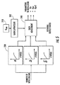
- FIG. 1 illustrates a block diagram of a wind farm 100 having multiple wind turbine generators 110 coupled with a transmission grid 190.
- FIG. 1 illustrates three wind generators 110; however, any number of wind generators can be included in a wind farm.
- Each wind turbine generator 110 includes a local controller that is responsive to the conditions of the wind turbine generator being controlled.
- the controller for each wind turbine generator senses only the terminal voltage and current (via potential and current transformers). The sensed voltage and current are used by the local controller to provide an appropriate response to cause the wind turbine generator 110 to provide the desired reactive power.
- Each wind turbine generator 110 is coupled to collector bus 120 through generator connection transformers 115 to provide real and reactive power (labeled P wg and Q wg , respectively) to collector bus 120.
- Generator connection transformers and collector buses are known in the art.
- the wind farm 100 provides real and reactive power output (labeled P wf and Q wf , respectively) via wind farm main transformer 130.
- the farm-level controller 150 senses the wind farm output, as well as the voltage at the point of common coupling (PCC) 140, to provide a Q command signal 105 (Q CMD ) that indicates desired reactive power at the generator terminals to ensure a reasonable distribution of reactive power among the wind turbines.
- this Q command signal (Q CMD ) 105 may be generated as the local or operator level (indicated by the "Local" line in FIG. 1 ), for example in the event that the wind turbine generator is in manual mode or otherwise not in communication with the wind farm controller 150, as explained in greater detail below.
- the controller 150 may include one or more processor(s) 152 and associated memory device(s) 154 configured to perform a variety of computer-implemented functions (e.g., performing the methods, steps, calculations and the like and storing relevant data as disclosed herein). Additionally, the controller 150 may also include a communications module 156 to facilitate communications between the controller 150 and the various components of the wind farm 100.
- the communications module 156 may include a sensor interface 158 (e.g., one or more analog-to-digital converters) to permit signals transmitted from one or more sensors 160, 162, 164 to be converted into signals that can be understood and processed by the processors 152.
- the sensors 160, 162, 164 may be communicatively coupled to the communications module 156 using any suitable means.
- the sensors 160, 162, 164 are coupled to the sensor interface 158 via a wired connection.
- the sensors 160, 162, 164 may be coupled to the sensor interface 158 via a wireless connection, such as by using any suitable wireless communications protocol known in the art.
- the term "processor” refers not only to integrated circuits referred to in the art as being included in a computer, but also refers to a controller, a microcontroller, a microcomputer, a programmable logic controller (PLC), an application specific integrated circuit, and other programmable circuits.
- the memory device(s) 154 may generally comprise memory element(s) including, but not limited to, computer readable medium (e.g., random access memory (RAM)), computer readable non-volatile medium (e.g., a flash memory), a floppy disk, a compact disc-read only memory (CD-ROM), a magneto-optical disk (MOD), a digital versatile disc (DVD) and/or other suitable memory elements.
- RAM random access memory
- CD-ROM compact disc-read only memory
- MOD magneto-optical disk
- DVD digital versatile disc
- Such memory device(s) 154 may generally be configured to store suitable computer-readable instructions that, when implemented by the processor(s) 152, configure the controller 150 to perform various functions as described herein.
- the sensors 160, 162, 164 may include any suitable sensors configured to provide feedback measurements to the farm controller 150.
- the sensors 160, 162, 164 may be any one of or combination of the following: voltage sensors, current sensors, and/or any other suitable sensors.
- the farm controller 150 as described herein includes a voltage control system 200 configured to improve reactive power speed-of-response of the wind farm 100.
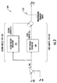
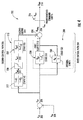
- the voltage control system 200 generally describes any suitable voltage regulator that is configured to regulate and/or stabilize voltage levels used by the processor(s) 152 of other elements of the farm controller 150. More specifically, FIG. 3 illustrates a simplified, block diagram of one embodiment of the voltage control system 200 according to the present disclosure; whereas FIG. 4 illustrates a detailed, block diagram of another embodiment of the voltage control system 200, particularly illustrating further details of the control paths.
- the voltage control system 200 receives a voltage feedback signal 204 (V fbk ) from the power grid 190 as well as a voltage reference signal 202 (V ref ).
- the voltage reference signal 202 may be any suitable voltage reference determined by the farm controller 150 or input manually by an operator.
- the voltage feedback signal 204 is indicative of the actual voltage of the power grid 190.
- the voltage control system 200 determines a linear voltage error signal 206 (V err ) as a function of the voltage feedback signal 204 and the voltage reference signal 202.
- the difference between the voltage feedback signal 204 and the voltage reference signal 202 is the linear voltage error signal 206, which can ultimately be reduced by the voltage control system 200 to cause the feedback voltage 204 to follow the reference voltage 202.
- the voltage control system 200 Based on the linear voltage error signal 206, the voltage control system 200 generates a reactive power command (e.g. Q CMD ), which is used to improve reactive power speed-of-response of the wind farm 100. More specifically, the voltage control system 200 generates a first output 212 based on the linear voltage error 206 via a first control path 224 having a first voltage regulator 208.
- the first voltage regulator 208 may be a proportional integral (PI) controller that has a closed-loop time constant in the range of 0.5 to 10 seconds (e.g. 3 seconds, 5 seconds, 5.5 seconds).
- the PI controller 208 includes a proportional path and an integral path.
- the proportional path includes a first proportional integrator 228 that is associated with a filtering element having a bandwidth typically greater than the closed-loop bandwidth of the windfarm voltage control system.
- the integral path includes a second integrator 230.
- the PI controller 208 can be limited based on predetermined integral limits as shown.
- each of the integrators 228, 230 are associated with a state variable, namely S1 and S3, respectively.
- a state variable generally refers to a variable that is used to describe the mathematical "state" of a dynamic system, e.g. the integrators 228, 230.
- the voltage control system 200 also generates a second output 214 via a second control path 226 having a second voltage regulator 210.
- the second voltage regulator 210 may include a transient amplifier 217 and a deadband 220 followed by a filtered proportional path having an integrator 232 that is associated with the filtering state variable S2.
- a deadband encompasses its broad ordinary meaning and generally refers to a component of a voltage regulator having an interval of a signal domain wherein no action occurs. As such, a deadband typically prevents oscillation or hunting in proportional control systems.
- the transient amplifier 217 is associated with a certain transfer function, for example, 1+sT 1 /1+sT 2 , wherein T 1 and T 2 are time constants and s is state variable S4. More specifically, the transient amplifier 217 is configured to amplify fast voltage changes in the power grid 190 so as to generate non-linear voltage error 215 (e.g. V err1 ). The deadband 220 can then determine another non-linear voltage error 222 (V err2 ) as a non-linear function of the voltage error signal 215.
- non-linear voltage error 215 e.g. V err1
- the deadband 220 can then determine another non-linear voltage error 222 (V err2 ) as a non-linear function of the voltage error signal 215.
- the integrator 232 may be associated with the filtering element in the filtered proportional controller.
- controllers can also be used, for example, proportional integral (PI) controllers, proportional derivative (PD) controllers, a proportional integral derivative (PID) controllers, state space controllers, or similar.
- PI proportional integral
- PD proportional derivative
- PID proportional integral derivative
- the second voltage regulator 210 may be configured to generate the second output 214 using, for example, a hysteresis function. More specifically, in particular embodiments, the second voltage regulator 210 may be configured to determine a non-linear time constant (e.g.
- T 1 , T 2 , and/or T v2 as a function of the voltage errors, namely V err1 215, V err 206 and V err2 222, and/or past history of the non-linear integrator 232.
- the integrator 232 is configured to calculate the second input 214 as a function of the non-linear voltage error 222, the proportional gain K pv2 , and/or the time constant T v2 . If the linear voltage error 206 is high, the non-linear voltage error 222 will move fast and provide improved reactive power speed-of-response. However, the increased speed can cause instability in the power grid 190.
- the voltage control system 200 is also configured to provide stable grid control using various suitable control algorithms.
- the integrator 232 is configured to adjust the time constant T v2 , so as to provide stable grid control, which is discussed in more detail below in regards to FIG. 9 .
- the second output 214 can be updated using the non-linear voltage error 222, the non-linear gain parameter K pv2 , and/or the adjusted non-linear time constant T v2 .
- the integrator 232 is also configured to determine a derivative of the second state variable S2. If the second state variable S2 and the derivative of the second state variable S2 are negative and the non-linear voltage error 222 is negative, the voltage control system 200 is configured to maintain or freeze the state variables (e.g. S1, S2, S3, and/or S4) at their present values for as long as the conditions are satisfied. In addition, the voltage control system 200 is configured to maintain or freeze the state variables at their present values for as long as the second state variable S2 is positive, the derivative of the second state variable S2 is negative, and the non-linear voltage error 222 is positive.
- the state variables e.g. S1, S2, S3, and/or S4
- the voltage control system 200 may maintain or freeze the state variables at their present values if the voltage feedback 204 is outside of a predetermined voltage range.
- the predetermined voltage range may be any suitable range.
- the predetermined voltage range may be from about 70% to about 110% of a nominal voltage.
- the previous conditions, when satisfied, indicate that a temporary, abnormal voltage condition is occurring in the power grid.
- the voltage control system 200 is configured to freeze the integrators until the condition passes so as to prevent forcing an extended abnormal voltage condition while the integrators respond after the originating grid disturbance is removed external to the wind farm 100. Accordingly, when the grid returns to within the normal range of operation, the voltage control system 200 provides fast reactive power response to the power grid 190 in a smooth manner.
- the voltage control system 200 is configured to combine the first and second outputs 212, 214 from the first and second control paths 224, 226 to obtain a reactive power output signal (e.g. Q CMDO 236).
- the Q CMDO 236 signal can be optionally limited by limiter 216 to a predetermined range between Q min and Q max (i.e. predetermined command limits) before sending the signal to each of the wind turbine generators 110.
- Q min and Q max are set equal to the rated reactive capability of the wind turbine generators 110. Alternate limits can also be used.
- the voltage control system 200 generates the reactive power command (e.g. Q CMD 218) as a function of the Q CMDO signal 236.
- the Q CMD signal 218 is reactive power command generated by the farm controller 150 that is sent to each of the wind turbine generators 110 to provide improved reactive power speed-of-response. Further, the reactive power command 218 is transmitted to the local controllers of the wind turbine generators 110 for generating reactive power based on the commands.
- the voltage control system 200 is configured to limit the first voltage regulator 208 based on the predetermined integral limits as shown.
- the limiter 216 is configured to limit the Q CMDO signal 236 based on the predetermined command limits (e.g. Q min and Q max ).
- the predetermined command limits of the limiter 216 can be greater or wider than the predetermined integral limits of integrator 230. This can be beneficial for wind turbine generators 110 having temporary capability beyond their steady-state rating.
- the limits on integrator 230 could be set to the steady-state rating of the wind turbine generators 110, ensuring that steady-state operation would be within their capability.
- the limits on the final output 218 would be set to the temporary capability of the wind turbine generators 110, thereby enabling the wind farm controller 150 to benefit from the higher wind turbine capability to manage grid transients.
- all of the limits discussed with respect to FIGS. 3 and 4 are non-windup limits; however, in alternate embodiments, a subset of the limits can be non-windup limits.
- the limits have been discussed in terms of fixed parameters; however, dynamically variable parameters provided by, for example, a lookup table or a processor or state machine executing a control algorithm can provide the limits. Such a dynamically variable limit may be based upon a current rating of the generators 110 and a contemporaneous real power output of the wind farm 100.
- the farm controller 150 may also determine one or more voltage regulator parameters for the integrators 228, 230, 232.
- the voltage regulator parameters may include proportional gains (e.g. K pv2 , K pv ), integral gains (e.g. K iv ), time constants (e.g. T 1 , T 2 , T v , T v2 ), combinations thereof, or similar.
- the farm controller 150 may be configured to vary or adjust the voltage regulator parameters based on a number of online wind turbines in the wind farm 100 and/or a status of one or more devices external to the wind farm 100.
- the external devices for example, may include transmission lines, generators, etc.
- the farm controller 150 receives a number of wind turbine generators online and inputs the number into one or more parameter graphs 238. Based on the graphs 238, the farm controller 150 can determines a gain adjustment 240 that can be sent to the voltage control system 200 to update the parameters. More specifically, as shown, the gain adjustment 240 may receive a status of one or more external devices. Additionally, a gain supervisor 242 may be included that monitors the control signals for sustained oscillatory behavior that may be due to excessive response from the wind farm controller 150 in some unanticipated grid condition. As such, the gain supervisor 242 initiates a gain reduction to restore stability to the wind farm control. Such gain supervisor functions are known in the art. The inputs of the gain supervisor 242 may vary, but generally include control signals such as the final output of the controller 150 (e.g. Q CMD 218), the voltage feedback signal 204 from the grid 190, and/or a combination of such signals or similar.
- control signals such as the final output of the controller 150 (e.g. Q CMD 218), the voltage feedback
- the method 300 includes determining, via a non-linear voltage regulator, a non-linear voltage error as a function of a linear voltage error.
- the method 300 includes calculating a non-linear time constant as a function of at least one of the non-linear voltage error and/or history of the non-linear voltage regulator.
- the method 300 includes determining an output of the non-linear voltage regulator based on at least one of the non-linear voltage error, a non-linear gain parameter, or the non-linear time constant.
- FIGS. 7-9 various advantages of operating the wind farm according to the present disclosure are illustrated. More specifically, FIGS. 7-9 illustrate the response of voltage (e.g.V fbk ) and reactive power command (e.g. Q CMD ) versus time to a capacitor operation in the transmission grid 190.
- the capacitor operation causes the voltage V pcc at the PCC 140 to increase.
- the voltage feedback signal 204 of the voltage control system 200 consequently increases.
- FIGS. 7-9 illustrate how the voltage control system 200 modifies the reactive power command (e.g. Q CMD ) to bring the voltage feedback signal 204 close to the initial value.
- FIG. 7 illustrates multiple graphs of voltage (e.g. V fbk ) and reactive power command (e.g. Q CMD ) versus time, respectively, for prior art systems
- FIG. 8 illustrates multiple graphs of voltage (e.g. V fbk ) and reactive power command (e.g. Q CMD ) versus time, respectively, according to the present disclosure
- FIG. 9 illustrates the effects of the non-linear control path but without the time constant (e.g. T v2 ) adjustment technology.
- the reactive power response 246 for prior art wind farms requires a certain period of time to reduce the reactive power command 246 and cause the voltage feedback 244 to approximate the value before the capacitor operation.
- FIG. 9 illustrates the effects of the non-linear control path but without the time constant (e.g. T v2 ) adjustment technology.
- the reactive power response 246 for prior art wind farms requires a certain period of time to reduce the reactive power command 246 and cause the voltage feedback 244 to approximate the value before the capacitor operation
- the reactive power response 256 for the wind farm 100 of the present disclosure has a faster reduction and results in a fast and stable restoration of the voltage feedback to its initial value.
- the graphs illustrate the behavior of the voltage feedback and reactive power signals 264, 266 without the adjustments of the integrator of state variable S2 in the block 232 of the second control path 226. It can be observed that the initial reduction of the reactive power command is the same as in FIG 8 . After the initial reactive power command reduction, an oscillatory response is observed.
Landscapes
- Engineering & Computer Science (AREA)
- Power Engineering (AREA)
- Life Sciences & Earth Sciences (AREA)
- Sustainable Development (AREA)
- Sustainable Energy (AREA)
- Chemical & Material Sciences (AREA)
- Combustion & Propulsion (AREA)
- Mechanical Engineering (AREA)
- General Engineering & Computer Science (AREA)
- Supply And Distribution Of Alternating Current (AREA)
- Control Of Eletrric Generators (AREA)
- Wind Motors (AREA)
Applications Claiming Priority (1)
| Application Number | Priority Date | Filing Date | Title |
|---|---|---|---|
| US14/642,869 US9831810B2 (en) | 2015-03-10 | 2015-03-10 | System and method for improved reactive power speed-of-response for a wind farm |
Publications (2)
| Publication Number | Publication Date |
|---|---|
| EP3068007A1 true EP3068007A1 (de) | 2016-09-14 |
| EP3068007B1 EP3068007B1 (de) | 2020-11-04 |
Family
ID=55524177
Family Applications (1)
| Application Number | Title | Priority Date | Filing Date |
|---|---|---|---|
| EP16159134.2A Active EP3068007B1 (de) | 2015-03-10 | 2016-03-08 | System und verfahren für verbesserte reaktionszeit von reaktiver leistung für einen windpark |
Country Status (6)
| Country | Link |
|---|---|
| US (1) | US9831810B2 (de) |
| EP (1) | EP3068007B1 (de) |
| CN (1) | CN205811554U (de) |
| BR (1) | BR102016005163B1 (de) |
| DK (1) | DK3068007T3 (de) |
| ES (1) | ES2849023T3 (de) |
Cited By (6)
| Publication number | Priority date | Publication date | Assignee | Title |
|---|---|---|---|---|
| WO2018141892A1 (de) * | 2017-02-02 | 2018-08-09 | Wobben Properties Gmbh | Verfahren zum einspeisen elektrischer leistung in ein elektrisches versorgungsnetz |
| EP3392994A1 (de) * | 2017-04-19 | 2018-10-24 | Siemens Aktiengesellschaft | Verfahren zur lastflussregelung in einem gleichspannungsnetz |
| EP3547480A1 (de) * | 2018-03-30 | 2019-10-02 | General Electric Company | System und verfahren zur kompensation von generatorisch induziertem flimmern in einer windturbine |
| EP4030577A1 (de) * | 2021-01-13 | 2022-07-20 | Vestas Wind Systems A/S | Verfahren zur steuerung eines erneuerbaren energieparks unter einhaltung der verpflichtungen gegenüber einem stromnetz |
| US11437825B2 (en) | 2019-01-04 | 2022-09-06 | Vestas Wind Systems A/S | Hybrid renewable power plant |
| EP4175105A3 (de) * | 2021-10-27 | 2023-05-10 | General Electric Renovables España S.L. | System und verfahren zur verringerung der instabilität bei einem blindleistungsbefehl einer wechselrichterbasierten ressource |
Families Citing this family (25)
| Publication number | Priority date | Publication date | Assignee | Title |
|---|---|---|---|---|
| US9831810B2 (en) * | 2015-03-10 | 2017-11-28 | General Electric Company | System and method for improved reactive power speed-of-response for a wind farm |
| DK3200303T3 (da) * | 2016-01-29 | 2024-04-29 | Siemens Gamesa Renewable Energy As | Drift af en vindmølle i en vindmøllepark |
| US10396694B2 (en) * | 2016-03-17 | 2019-08-27 | General Electric Company | System and method for minimizing reactive current to limit rotor modulation index on a power converter |
| EP3452877B1 (de) * | 2016-05-03 | 2023-04-26 | Vestas Wind Systems A/S | Steuerung einer windturbine während eines niederspannungsnetzereignisses mittels mpc |
| US10519933B2 (en) * | 2017-04-24 | 2019-12-31 | General Electric Company | Method of operating a wind turbine system including an energy storage system |
| US10756658B2 (en) * | 2017-07-06 | 2020-08-25 | General Electric Company | Allocating reactive power production for doubly fed induction generator wind turbine system |
| US10727671B2 (en) | 2017-08-08 | 2020-07-28 | Solar Turbines Incorporated | Gas turbine electrical power system and control strategy for limiting reverse power shutdown |
| EP3729592B1 (de) | 2017-12-21 | 2022-09-07 | Vestas Wind Systems A/S | Verbesserungen im zusammenhang mit der stromeinspeisung in windkraftanlagen |
| CN108808729B (zh) * | 2018-06-07 | 2024-09-20 | 中国华电科工集团有限公司 | 一种发电厂电气主接线的电路结构 |
| WO2020121362A1 (ja) * | 2018-12-10 | 2020-06-18 | 三菱電機株式会社 | 電力変換システム及びその管理装置、並びに、分散電源装置 |
| US11521771B2 (en) | 2019-04-03 | 2022-12-06 | General Electric Company | System for quench protection of superconducting machines, such as a superconducting wind turbine generator |
| US10978943B2 (en) | 2019-04-03 | 2021-04-13 | General Electric Company | System and method for auto-ramping and energy dump for a superconducting wind turbine generator |
| US10742149B1 (en) | 2019-04-22 | 2020-08-11 | General Electric Company | System and method for reactive power control of a wind turbine by varying switching frequency of rotor side converter |
| US11056884B2 (en) | 2019-05-06 | 2021-07-06 | General Electric Company | Wind turbine system with integrated reactive power compensation device |
| US10581247B1 (en) * | 2019-05-06 | 2020-03-03 | General Electric Company | System and method for reactive power control of wind turbines in a wind farm supported with auxiliary reactive power compensation |
| US10731628B1 (en) | 2019-05-06 | 2020-08-04 | General Electric Company | System and method for coordinated control of reactive power from a generator and a reactive power compensation device in a wind turbine system |
| US10790668B1 (en) | 2019-05-06 | 2020-09-29 | General Electric Company | Method for reactive power oscillation damping for a wind turbine system with integrated reactive power compensation device |
| US10865773B1 (en) * | 2019-05-22 | 2020-12-15 | General Electric Company | System and method for mitigating flicker in a power grid from a wind turbine power system |
| US10767630B1 (en) * | 2019-05-28 | 2020-09-08 | General Electric Company | System and method for operating a wind farm during low wind speeds |
| CN113013913B (zh) * | 2019-12-19 | 2024-01-23 | 金风科技股份有限公司 | 风电场无功电压控制系统和方法 |
| US11233402B2 (en) | 2020-01-06 | 2022-01-25 | General Electric Company | System and method for stabilizing weak grids with one or more wind farms connected thereto |
| WO2021223829A1 (en) * | 2020-05-06 | 2021-11-11 | Vestas Wind Systems A/S | Method and control systems for voltage control in renewable energy power plant |
| US11530685B2 (en) | 2020-08-20 | 2022-12-20 | General Electric Company | System and method for managing output flicker generated by a wind farm |
| CN113098072B (zh) * | 2021-03-31 | 2022-09-02 | 广东电网有限责任公司 | 双馈风机电压反馈控制优化方法、装置、设备和存储介质 |
| US11894681B2 (en) * | 2021-10-01 | 2024-02-06 | General Electric Company | System and method for power oscillation damping in a power generating system |
Citations (2)
| Publication number | Priority date | Publication date | Assignee | Title |
|---|---|---|---|---|
| GB2142483A (en) * | 1983-06-28 | 1985-01-16 | Gen Electric | Control for a force commutated current source var generator |
| US7224081B2 (en) | 2003-09-03 | 2007-05-29 | General Electric Company | Voltage control for wind generators |
Family Cites Families (14)
| Publication number | Priority date | Publication date | Assignee | Title |
|---|---|---|---|---|
| US5570007A (en) * | 1993-07-09 | 1996-10-29 | General Electric Company | Method and apparatus for static VAR compensator voltage regulation |
| DE10136974A1 (de) | 2001-04-24 | 2002-11-21 | Aloys Wobben | Verfahren zum Betreiben einer Windenergieanlage |
| US6924565B2 (en) | 2003-08-18 | 2005-08-02 | General Electric Company | Continuous reactive power support for wind turbine generators |
| US7531911B2 (en) | 2006-12-22 | 2009-05-12 | Ingeteam Energy, S.A. | Reactive power control for operating a wind farm |
| US8041465B2 (en) * | 2008-10-09 | 2011-10-18 | General Electric Company | Voltage control at windfarms |
| ES2382786B1 (es) * | 2009-03-17 | 2013-05-07 | Acciona Windpower S.A. | Metodo y sistema de control de tension de una central de generacion electrica y parque eolico |
| US9124140B2 (en) * | 2009-04-01 | 2015-09-01 | The Board Of Trustees Of The University Of Alabama | Intelligent power converter control for grid integration of renewable energies |
| US7923862B2 (en) * | 2009-10-06 | 2011-04-12 | General Electric Company | Reactive power regulation and voltage support for renewable energy plants |
| US20140350743A1 (en) * | 2012-08-27 | 2014-11-27 | Nec Laboratories America, Inc. | Tiered power management system for microgrids |
| EP2711543B1 (de) * | 2012-09-21 | 2016-08-17 | Siemens Aktiengesellschaft | Betrieb einer Windturbine und eines Windparks in unterschiedlichen Netzstärken |
| US9680307B2 (en) * | 2012-12-21 | 2017-06-13 | General Electric Company | System and method for voltage regulation of a renewable energy plant |
| CN104104221B (zh) * | 2013-04-11 | 2017-05-17 | 通用电气公司 | 具有有功无功功率解耦补偿机制的能量转换系统和方法 |
| US9318988B2 (en) * | 2013-09-05 | 2016-04-19 | General Electric Company | System and method for voltage control of wind generators |
| US9831810B2 (en) * | 2015-03-10 | 2017-11-28 | General Electric Company | System and method for improved reactive power speed-of-response for a wind farm |
-
2015
- 2015-03-10 US US14/642,869 patent/US9831810B2/en active Active
-
2016
- 2016-03-08 EP EP16159134.2A patent/EP3068007B1/de active Active
- 2016-03-08 ES ES16159134T patent/ES2849023T3/es active Active
- 2016-03-08 DK DK16159134.2T patent/DK3068007T3/da active
- 2016-03-09 BR BR102016005163-0A patent/BR102016005163B1/pt active IP Right Grant
- 2016-03-10 CN CN201620182373.XU patent/CN205811554U/zh active Active
Patent Citations (2)
| Publication number | Priority date | Publication date | Assignee | Title |
|---|---|---|---|---|
| GB2142483A (en) * | 1983-06-28 | 1985-01-16 | Gen Electric | Control for a force commutated current source var generator |
| US7224081B2 (en) | 2003-09-03 | 2007-05-29 | General Electric Company | Voltage control for wind generators |
Cited By (9)
| Publication number | Priority date | Publication date | Assignee | Title |
|---|---|---|---|---|
| WO2018141892A1 (de) * | 2017-02-02 | 2018-08-09 | Wobben Properties Gmbh | Verfahren zum einspeisen elektrischer leistung in ein elektrisches versorgungsnetz |
| US10868427B2 (en) | 2017-02-02 | 2020-12-15 | Wobben Properties Gmbh | Method for feeding electrical power into an electrical supply network |
| EP3392994A1 (de) * | 2017-04-19 | 2018-10-24 | Siemens Aktiengesellschaft | Verfahren zur lastflussregelung in einem gleichspannungsnetz |
| EP3547480A1 (de) * | 2018-03-30 | 2019-10-02 | General Electric Company | System und verfahren zur kompensation von generatorisch induziertem flimmern in einer windturbine |
| US10491146B2 (en) | 2018-03-30 | 2019-11-26 | General Electric Company | System and method for compensating for generator-induced flicker in a wind turbine |
| US11437825B2 (en) | 2019-01-04 | 2022-09-06 | Vestas Wind Systems A/S | Hybrid renewable power plant |
| EP4030577A1 (de) * | 2021-01-13 | 2022-07-20 | Vestas Wind Systems A/S | Verfahren zur steuerung eines erneuerbaren energieparks unter einhaltung der verpflichtungen gegenüber einem stromnetz |
| EP4175105A3 (de) * | 2021-10-27 | 2023-05-10 | General Electric Renovables España S.L. | System und verfahren zur verringerung der instabilität bei einem blindleistungsbefehl einer wechselrichterbasierten ressource |
| US11901735B2 (en) | 2021-10-27 | 2024-02-13 | General Electric Renovables Espana, S.L. | System and method for reducing instability in reactive power command of an inverter-based resource |
Also Published As
| Publication number | Publication date |
|---|---|
| US9831810B2 (en) | 2017-11-28 |
| CN205811554U (zh) | 2016-12-14 |
| BR102016005163B1 (pt) | 2022-08-16 |
| EP3068007B1 (de) | 2020-11-04 |
| ES2849023T3 (es) | 2021-08-13 |
| US20160268940A1 (en) | 2016-09-15 |
| BR102016005163A2 (pt) | 2016-09-13 |
| DK3068007T3 (da) | 2021-02-08 |
Similar Documents
| Publication | Publication Date | Title |
|---|---|---|
| EP3068007B1 (de) | System und verfahren für verbesserte reaktionszeit von reaktiver leistung für einen windpark | |
| AU2016200826B2 (en) | System and method for controlling ramp rate of solar photovoltaic system | |
| CN109861242B (zh) | 一种风电参与电网一次调频的功率协调控制方法及系统 | |
| JP5102957B2 (ja) | 風力タービン発電機の制御方法および制御システム | |
| US9631608B2 (en) | Wind-power-plant control upon low-voltage grid faults | |
| US9203333B2 (en) | System and method for voltage control of wind generators | |
| EP2846434B1 (de) | System und Verfahren zur Spannungsregelung von Windgeneratoren | |
| KR101943588B1 (ko) | 풍력 발전 설비를 제어하기 위한 방법 | |
| TWI599135B (zh) | 用於操作風力發動機及/或風力發電廠之方法與調節及/或控制裝置及風力發動機與風力發電廠 | |
| US10865774B2 (en) | Wind turbine control method and system | |
| US20200063712A1 (en) | Inertial response for grid stability | |
| CN105934862B (zh) | 具有改进的额定值跃变特性的风电场调节装置 | |
| CN111492551A (zh) | 可再生能源发电厂的自适应有功功率控制 | |
| EP3926783A1 (de) | System und verfahren zur dynamischen schätzung der umrichterbasierten ressourcenblindleistungsfähigkeit | |
| JP2020506664A (ja) | 電力供給ネットワークへの電力供給方法 | |
| Konstantinopoulos et al. | Dynamic active power control in type-3 wind turbines for transient stability enhancement | |
| CN107785930B (zh) | 一种风电场风机无功和电压协同控制方法 | |
| CN113471986B (zh) | 调节风电场有功功率的方法、控制设备及风电场的控制器 |
Legal Events
| Date | Code | Title | Description |
|---|---|---|---|
| PUAI | Public reference made under article 153(3) epc to a published international application that has entered the european phase |
Free format text: ORIGINAL CODE: 0009012 |
|
| AK | Designated contracting states |
Kind code of ref document: A1 Designated state(s): AL AT BE BG CH CY CZ DE DK EE ES FI FR GB GR HR HU IE IS IT LI LT LU LV MC MK MT NL NO PL PT RO RS SE SI SK SM TR |
|
| AX | Request for extension of the european patent |
Extension state: BA ME |
|
| STAA | Information on the status of an ep patent application or granted ep patent |
Free format text: STATUS: REQUEST FOR EXAMINATION WAS MADE |
|
| 17P | Request for examination filed |
Effective date: 20170314 |
|
| RBV | Designated contracting states (corrected) |
Designated state(s): AL AT BE BG CH CY CZ DE DK EE ES FI FR GB GR HR HU IE IS IT LI LT LU LV MC MK MT NL NO PL PT RO RS SE SI SK SM TR |
|
| STAA | Information on the status of an ep patent application or granted ep patent |
Free format text: STATUS: EXAMINATION IS IN PROGRESS |
|
| 17Q | First examination report despatched |
Effective date: 20180731 |
|
| GRAP | Despatch of communication of intention to grant a patent |
Free format text: ORIGINAL CODE: EPIDOSNIGR1 |
|
| STAA | Information on the status of an ep patent application or granted ep patent |
Free format text: STATUS: GRANT OF PATENT IS INTENDED |
|
| INTG | Intention to grant announced |
Effective date: 20200527 |
|
| GRAS | Grant fee paid |
Free format text: ORIGINAL CODE: EPIDOSNIGR3 |
|
| GRAA | (expected) grant |
Free format text: ORIGINAL CODE: 0009210 |
|
| STAA | Information on the status of an ep patent application or granted ep patent |
Free format text: STATUS: THE PATENT HAS BEEN GRANTED |
|
| AK | Designated contracting states |
Kind code of ref document: B1 Designated state(s): AL AT BE BG CH CY CZ DE DK EE ES FI FR GB GR HR HU IE IS IT LI LT LU LV MC MK MT NL NO PL PT RO RS SE SI SK SM TR |
|
| REG | Reference to a national code |
Ref country code: GB Ref legal event code: FG4D |
|
| REG | Reference to a national code |
Ref country code: CH Ref legal event code: EP |
|
| REG | Reference to a national code |
Ref country code: AT Ref legal event code: REF Ref document number: 1332072 Country of ref document: AT Kind code of ref document: T Effective date: 20201115 |
|
| REG | Reference to a national code |
Ref country code: DE Ref legal event code: R096 Ref document number: 602016046985 Country of ref document: DE |
|
| REG | Reference to a national code |
Ref country code: IE Ref legal event code: FG4D |
|
| REG | Reference to a national code |
Ref country code: DK Ref legal event code: T3 Effective date: 20210203 |
|
| REG | Reference to a national code |
Ref country code: NL Ref legal event code: MP Effective date: 20201104 |
|
| REG | Reference to a national code |
Ref country code: AT Ref legal event code: MK05 Ref document number: 1332072 Country of ref document: AT Kind code of ref document: T Effective date: 20201104 |
|
| PG25 | Lapsed in a contracting state [announced via postgrant information from national office to epo] |
Ref country code: PT Free format text: LAPSE BECAUSE OF FAILURE TO SUBMIT A TRANSLATION OF THE DESCRIPTION OR TO PAY THE FEE WITHIN THE PRESCRIBED TIME-LIMIT Effective date: 20210304 Ref country code: RS Free format text: LAPSE BECAUSE OF FAILURE TO SUBMIT A TRANSLATION OF THE DESCRIPTION OR TO PAY THE FEE WITHIN THE PRESCRIBED TIME-LIMIT Effective date: 20201104 Ref country code: FI Free format text: LAPSE BECAUSE OF FAILURE TO SUBMIT A TRANSLATION OF THE DESCRIPTION OR TO PAY THE FEE WITHIN THE PRESCRIBED TIME-LIMIT Effective date: 20201104 Ref country code: NO Free format text: LAPSE BECAUSE OF FAILURE TO SUBMIT A TRANSLATION OF THE DESCRIPTION OR TO PAY THE FEE WITHIN THE PRESCRIBED TIME-LIMIT Effective date: 20210204 Ref country code: GR Free format text: LAPSE BECAUSE OF FAILURE TO SUBMIT A TRANSLATION OF THE DESCRIPTION OR TO PAY THE FEE WITHIN THE PRESCRIBED TIME-LIMIT Effective date: 20210205 |
|
| PG25 | Lapsed in a contracting state [announced via postgrant information from national office to epo] |
Ref country code: AT Free format text: LAPSE BECAUSE OF FAILURE TO SUBMIT A TRANSLATION OF THE DESCRIPTION OR TO PAY THE FEE WITHIN THE PRESCRIBED TIME-LIMIT Effective date: 20201104 Ref country code: BG Free format text: LAPSE BECAUSE OF FAILURE TO SUBMIT A TRANSLATION OF THE DESCRIPTION OR TO PAY THE FEE WITHIN THE PRESCRIBED TIME-LIMIT Effective date: 20210204 Ref country code: IS Free format text: LAPSE BECAUSE OF FAILURE TO SUBMIT A TRANSLATION OF THE DESCRIPTION OR TO PAY THE FEE WITHIN THE PRESCRIBED TIME-LIMIT Effective date: 20210304 Ref country code: LV Free format text: LAPSE BECAUSE OF FAILURE TO SUBMIT A TRANSLATION OF THE DESCRIPTION OR TO PAY THE FEE WITHIN THE PRESCRIBED TIME-LIMIT Effective date: 20201104 Ref country code: PL Free format text: LAPSE BECAUSE OF FAILURE TO SUBMIT A TRANSLATION OF THE DESCRIPTION OR TO PAY THE FEE WITHIN THE PRESCRIBED TIME-LIMIT Effective date: 20201104 Ref country code: SE Free format text: LAPSE BECAUSE OF FAILURE TO SUBMIT A TRANSLATION OF THE DESCRIPTION OR TO PAY THE FEE WITHIN THE PRESCRIBED TIME-LIMIT Effective date: 20201104 |
|
| REG | Reference to a national code |
Ref country code: LT Ref legal event code: MG9D |
|
| PG25 | Lapsed in a contracting state [announced via postgrant information from national office to epo] |
Ref country code: HR Free format text: LAPSE BECAUSE OF FAILURE TO SUBMIT A TRANSLATION OF THE DESCRIPTION OR TO PAY THE FEE WITHIN THE PRESCRIBED TIME-LIMIT Effective date: 20201104 |
|
| PG25 | Lapsed in a contracting state [announced via postgrant information from national office to epo] |
Ref country code: SK Free format text: LAPSE BECAUSE OF FAILURE TO SUBMIT A TRANSLATION OF THE DESCRIPTION OR TO PAY THE FEE WITHIN THE PRESCRIBED TIME-LIMIT Effective date: 20201104 Ref country code: RO Free format text: LAPSE BECAUSE OF FAILURE TO SUBMIT A TRANSLATION OF THE DESCRIPTION OR TO PAY THE FEE WITHIN THE PRESCRIBED TIME-LIMIT Effective date: 20201104 Ref country code: CZ Free format text: LAPSE BECAUSE OF FAILURE TO SUBMIT A TRANSLATION OF THE DESCRIPTION OR TO PAY THE FEE WITHIN THE PRESCRIBED TIME-LIMIT Effective date: 20201104 Ref country code: EE Free format text: LAPSE BECAUSE OF FAILURE TO SUBMIT A TRANSLATION OF THE DESCRIPTION OR TO PAY THE FEE WITHIN THE PRESCRIBED TIME-LIMIT Effective date: 20201104 Ref country code: SM Free format text: LAPSE BECAUSE OF FAILURE TO SUBMIT A TRANSLATION OF THE DESCRIPTION OR TO PAY THE FEE WITHIN THE PRESCRIBED TIME-LIMIT Effective date: 20201104 Ref country code: LT Free format text: LAPSE BECAUSE OF FAILURE TO SUBMIT A TRANSLATION OF THE DESCRIPTION OR TO PAY THE FEE WITHIN THE PRESCRIBED TIME-LIMIT Effective date: 20201104 |
|
| REG | Reference to a national code |
Ref country code: DE Ref legal event code: R097 Ref document number: 602016046985 Country of ref document: DE |
|
| REG | Reference to a national code |
Ref country code: ES Ref legal event code: FG2A Ref document number: 2849023 Country of ref document: ES Kind code of ref document: T3 Effective date: 20210813 |
|
| PLBE | No opposition filed within time limit |
Free format text: ORIGINAL CODE: 0009261 |
|
| STAA | Information on the status of an ep patent application or granted ep patent |
Free format text: STATUS: NO OPPOSITION FILED WITHIN TIME LIMIT |
|
| 26N | No opposition filed |
Effective date: 20210805 |
|
| PG25 | Lapsed in a contracting state [announced via postgrant information from national office to epo] |
Ref country code: AL Free format text: LAPSE BECAUSE OF FAILURE TO SUBMIT A TRANSLATION OF THE DESCRIPTION OR TO PAY THE FEE WITHIN THE PRESCRIBED TIME-LIMIT Effective date: 20201104 Ref country code: IT Free format text: LAPSE BECAUSE OF FAILURE TO SUBMIT A TRANSLATION OF THE DESCRIPTION OR TO PAY THE FEE WITHIN THE PRESCRIBED TIME-LIMIT Effective date: 20201104 Ref country code: NL Free format text: LAPSE BECAUSE OF FAILURE TO SUBMIT A TRANSLATION OF THE DESCRIPTION OR TO PAY THE FEE WITHIN THE PRESCRIBED TIME-LIMIT Effective date: 20201104 Ref country code: MC Free format text: LAPSE BECAUSE OF FAILURE TO SUBMIT A TRANSLATION OF THE DESCRIPTION OR TO PAY THE FEE WITHIN THE PRESCRIBED TIME-LIMIT Effective date: 20201104 |
|
| REG | Reference to a national code |
Ref country code: CH Ref legal event code: PL |
|
| GBPC | Gb: european patent ceased through non-payment of renewal fee |
Effective date: 20210308 |
|
| PG25 | Lapsed in a contracting state [announced via postgrant information from national office to epo] |
Ref country code: SI Free format text: LAPSE BECAUSE OF FAILURE TO SUBMIT A TRANSLATION OF THE DESCRIPTION OR TO PAY THE FEE WITHIN THE PRESCRIBED TIME-LIMIT Effective date: 20201104 |
|
| REG | Reference to a national code |
Ref country code: BE Ref legal event code: MM Effective date: 20210331 |
|
| PG25 | Lapsed in a contracting state [announced via postgrant information from national office to epo] |
Ref country code: FR Free format text: LAPSE BECAUSE OF NON-PAYMENT OF DUE FEES Effective date: 20210331 Ref country code: GB Free format text: LAPSE BECAUSE OF NON-PAYMENT OF DUE FEES Effective date: 20210308 Ref country code: IE Free format text: LAPSE BECAUSE OF NON-PAYMENT OF DUE FEES Effective date: 20210308 Ref country code: CH Free format text: LAPSE BECAUSE OF NON-PAYMENT OF DUE FEES Effective date: 20210331 Ref country code: LI Free format text: LAPSE BECAUSE OF NON-PAYMENT OF DUE FEES Effective date: 20210331 Ref country code: LU Free format text: LAPSE BECAUSE OF NON-PAYMENT OF DUE FEES Effective date: 20210308 |
|
| PG25 | Lapsed in a contracting state [announced via postgrant information from national office to epo] |
Ref country code: IS Free format text: LAPSE BECAUSE OF FAILURE TO SUBMIT A TRANSLATION OF THE DESCRIPTION OR TO PAY THE FEE WITHIN THE PRESCRIBED TIME-LIMIT Effective date: 20210304 |
|
| PG25 | Lapsed in a contracting state [announced via postgrant information from national office to epo] |
Ref country code: BE Free format text: LAPSE BECAUSE OF NON-PAYMENT OF DUE FEES Effective date: 20210331 |
|
| PG25 | Lapsed in a contracting state [announced via postgrant information from national office to epo] |
Ref country code: HU Free format text: LAPSE BECAUSE OF FAILURE TO SUBMIT A TRANSLATION OF THE DESCRIPTION OR TO PAY THE FEE WITHIN THE PRESCRIBED TIME-LIMIT; INVALID AB INITIO Effective date: 20160308 |
|
| PG25 | Lapsed in a contracting state [announced via postgrant information from national office to epo] |
Ref country code: CY Free format text: LAPSE BECAUSE OF FAILURE TO SUBMIT A TRANSLATION OF THE DESCRIPTION OR TO PAY THE FEE WITHIN THE PRESCRIBED TIME-LIMIT Effective date: 20201104 |
|
| P01 | Opt-out of the competence of the unified patent court (upc) registered |
Effective date: 20230530 |
|
| REG | Reference to a national code |
Ref country code: DE Ref legal event code: R082 Ref document number: 602016046985 Country of ref document: DE Representative=s name: ZIMMERMANN & PARTNER PATENTANWAELTE MBB, DE Ref country code: DE Ref legal event code: R082 Ref document number: 602016046985 Country of ref document: DE Ref country code: DE Ref legal event code: R081 Ref document number: 602016046985 Country of ref document: DE Owner name: GENERAL ELECTRIC RENOVABLES ESPANA, S.L., ES Free format text: FORMER OWNER: GENERAL ELECTRIC COMPANY, SCHENECTADY, NY, US |
|
| REG | Reference to a national code |
Ref country code: DE Ref legal event code: R082 Ref document number: 602016046985 Country of ref document: DE Representative=s name: ZIMMERMANN & PARTNER PATENTANWAELTE MBB, DE |
|
| PG25 | Lapsed in a contracting state [announced via postgrant information from national office to epo] |
Ref country code: MK Free format text: LAPSE BECAUSE OF FAILURE TO SUBMIT A TRANSLATION OF THE DESCRIPTION OR TO PAY THE FEE WITHIN THE PRESCRIBED TIME-LIMIT Effective date: 20201104 |
|
| PGFP | Annual fee paid to national office [announced via postgrant information from national office to epo] |
Ref country code: DE Payment date: 20240220 Year of fee payment: 9 |
|
| PGFP | Annual fee paid to national office [announced via postgrant information from national office to epo] |
Ref country code: DK Payment date: 20240220 Year of fee payment: 9 |
|
| PGFP | Annual fee paid to national office [announced via postgrant information from national office to epo] |
Ref country code: ES Payment date: 20240402 Year of fee payment: 9 |
|
| REG | Reference to a national code |
Ref country code: ES Ref legal event code: PC2A Owner name: GENERAL ELECTRIC RENOVABLES ESPANA S.L. Effective date: 20240809 |