EP3067739B1 - Display apparatus - Google Patents
Display apparatus Download PDFInfo
- Publication number
- EP3067739B1 EP3067739B1 EP16159042.7A EP16159042A EP3067739B1 EP 3067739 B1 EP3067739 B1 EP 3067739B1 EP 16159042 A EP16159042 A EP 16159042A EP 3067739 B1 EP3067739 B1 EP 3067739B1
- Authority
- EP
- European Patent Office
- Prior art keywords
- cooling path
- bottom chassis
- display apparatus
- cooling
- case
- Prior art date
- Legal status (The legal status is an assumption and is not a legal conclusion. Google has not performed a legal analysis and makes no representation as to the accuracy of the status listed.)
- Not-in-force
Links
- 238000001816 cooling Methods 0.000 claims description 204
- 238000005192 partition Methods 0.000 claims description 41
- 238000009792 diffusion process Methods 0.000 description 7
- 230000000694 effects Effects 0.000 description 7
- 238000009434 installation Methods 0.000 description 7
- 230000003287 optical effect Effects 0.000 description 7
- 239000004973 liquid crystal related substance Substances 0.000 description 4
- 230000002708 enhancing effect Effects 0.000 description 2
- 230000001133 acceleration Effects 0.000 description 1
- 230000004308 accommodation Effects 0.000 description 1
- 230000005540 biological transmission Effects 0.000 description 1
- 239000011521 glass Substances 0.000 description 1
- 238000010438 heat treatment Methods 0.000 description 1
- 239000007788 liquid Substances 0.000 description 1
- 239000011159 matrix material Substances 0.000 description 1
- 230000007246 mechanism Effects 0.000 description 1
- 230000001681 protective effect Effects 0.000 description 1
- 230000005855 radiation Effects 0.000 description 1
Images


Classifications
-
- G—PHYSICS
- G02—OPTICS
- G02F—OPTICAL DEVICES OR ARRANGEMENTS FOR THE CONTROL OF LIGHT BY MODIFICATION OF THE OPTICAL PROPERTIES OF THE MEDIA OF THE ELEMENTS INVOLVED THEREIN; NON-LINEAR OPTICS; FREQUENCY-CHANGING OF LIGHT; OPTICAL LOGIC ELEMENTS; OPTICAL ANALOGUE/DIGITAL CONVERTERS
- G02F1/00—Devices or arrangements for the control of the intensity, colour, phase, polarisation or direction of light arriving from an independent light source, e.g. switching, gating or modulating; Non-linear optics
- G02F1/01—Devices or arrangements for the control of the intensity, colour, phase, polarisation or direction of light arriving from an independent light source, e.g. switching, gating or modulating; Non-linear optics for the control of the intensity, phase, polarisation or colour
- G02F1/13—Devices or arrangements for the control of the intensity, colour, phase, polarisation or direction of light arriving from an independent light source, e.g. switching, gating or modulating; Non-linear optics for the control of the intensity, phase, polarisation or colour based on liquid crystals, e.g. single liquid crystal display cells
- G02F1/133—Constructional arrangements; Operation of liquid crystal cells; Circuit arrangements
- G02F1/1333—Constructional arrangements; Manufacturing methods
- G02F1/1335—Structural association of cells with optical devices, e.g. polarisers or reflectors
- G02F1/1336—Illuminating devices
-
- F—MECHANICAL ENGINEERING; LIGHTING; HEATING; WEAPONS; BLASTING
- F21—LIGHTING
- F21V—FUNCTIONAL FEATURES OR DETAILS OF LIGHTING DEVICES OR SYSTEMS THEREOF; STRUCTURAL COMBINATIONS OF LIGHTING DEVICES WITH OTHER ARTICLES, NOT OTHERWISE PROVIDED FOR
- F21V29/00—Protecting lighting devices from thermal damage; Cooling or heating arrangements specially adapted for lighting devices or systems
- F21V29/50—Cooling arrangements
- F21V29/70—Cooling arrangements characterised by passive heat-dissipating elements, e.g. heat-sinks
- F21V29/83—Cooling arrangements characterised by passive heat-dissipating elements, e.g. heat-sinks the elements having apertures, ducts or channels, e.g. heat radiation holes
-
- G—PHYSICS
- G02—OPTICS
- G02F—OPTICAL DEVICES OR ARRANGEMENTS FOR THE CONTROL OF LIGHT BY MODIFICATION OF THE OPTICAL PROPERTIES OF THE MEDIA OF THE ELEMENTS INVOLVED THEREIN; NON-LINEAR OPTICS; FREQUENCY-CHANGING OF LIGHT; OPTICAL LOGIC ELEMENTS; OPTICAL ANALOGUE/DIGITAL CONVERTERS
- G02F1/00—Devices or arrangements for the control of the intensity, colour, phase, polarisation or direction of light arriving from an independent light source, e.g. switching, gating or modulating; Non-linear optics
- G02F1/01—Devices or arrangements for the control of the intensity, colour, phase, polarisation or direction of light arriving from an independent light source, e.g. switching, gating or modulating; Non-linear optics for the control of the intensity, phase, polarisation or colour
- G02F1/13—Devices or arrangements for the control of the intensity, colour, phase, polarisation or direction of light arriving from an independent light source, e.g. switching, gating or modulating; Non-linear optics for the control of the intensity, phase, polarisation or colour based on liquid crystals, e.g. single liquid crystal display cells
- G02F1/133—Constructional arrangements; Operation of liquid crystal cells; Circuit arrangements
- G02F1/1333—Constructional arrangements; Manufacturing methods
- G02F1/133382—Heating or cooling of liquid crystal cells other than for activation, e.g. circuits or arrangements for temperature control, stabilisation or uniform distribution over the cell
- G02F1/133385—Heating or cooling of liquid crystal cells other than for activation, e.g. circuits or arrangements for temperature control, stabilisation or uniform distribution over the cell with cooling means, e.g. fans
-
- G—PHYSICS
- G02—OPTICS
- G02F—OPTICAL DEVICES OR ARRANGEMENTS FOR THE CONTROL OF LIGHT BY MODIFICATION OF THE OPTICAL PROPERTIES OF THE MEDIA OF THE ELEMENTS INVOLVED THEREIN; NON-LINEAR OPTICS; FREQUENCY-CHANGING OF LIGHT; OPTICAL LOGIC ELEMENTS; OPTICAL ANALOGUE/DIGITAL CONVERTERS
- G02F1/00—Devices or arrangements for the control of the intensity, colour, phase, polarisation or direction of light arriving from an independent light source, e.g. switching, gating or modulating; Non-linear optics
- G02F1/01—Devices or arrangements for the control of the intensity, colour, phase, polarisation or direction of light arriving from an independent light source, e.g. switching, gating or modulating; Non-linear optics for the control of the intensity, phase, polarisation or colour
- G02F1/13—Devices or arrangements for the control of the intensity, colour, phase, polarisation or direction of light arriving from an independent light source, e.g. switching, gating or modulating; Non-linear optics for the control of the intensity, phase, polarisation or colour based on liquid crystals, e.g. single liquid crystal display cells
- G02F1/133—Constructional arrangements; Operation of liquid crystal cells; Circuit arrangements
- G02F1/1333—Constructional arrangements; Manufacturing methods
- G02F1/1335—Structural association of cells with optical devices, e.g. polarisers or reflectors
- G02F1/1336—Illuminating devices
- G02F1/133602—Direct backlight
-
- F—MECHANICAL ENGINEERING; LIGHTING; HEATING; WEAPONS; BLASTING
- F21—LIGHTING
- F21V—FUNCTIONAL FEATURES OR DETAILS OF LIGHTING DEVICES OR SYSTEMS THEREOF; STRUCTURAL COMBINATIONS OF LIGHTING DEVICES WITH OTHER ARTICLES, NOT OTHERWISE PROVIDED FOR
- F21V29/00—Protecting lighting devices from thermal damage; Cooling or heating arrangements specially adapted for lighting devices or systems
- F21V29/50—Cooling arrangements
- F21V29/60—Cooling arrangements characterised by the use of a forced flow of gas, e.g. air
-
- G—PHYSICS
- G02—OPTICS
- G02F—OPTICAL DEVICES OR ARRANGEMENTS FOR THE CONTROL OF LIGHT BY MODIFICATION OF THE OPTICAL PROPERTIES OF THE MEDIA OF THE ELEMENTS INVOLVED THEREIN; NON-LINEAR OPTICS; FREQUENCY-CHANGING OF LIGHT; OPTICAL LOGIC ELEMENTS; OPTICAL ANALOGUE/DIGITAL CONVERTERS
- G02F1/00—Devices or arrangements for the control of the intensity, colour, phase, polarisation or direction of light arriving from an independent light source, e.g. switching, gating or modulating; Non-linear optics
- G02F1/01—Devices or arrangements for the control of the intensity, colour, phase, polarisation or direction of light arriving from an independent light source, e.g. switching, gating or modulating; Non-linear optics for the control of the intensity, phase, polarisation or colour
- G02F1/13—Devices or arrangements for the control of the intensity, colour, phase, polarisation or direction of light arriving from an independent light source, e.g. switching, gating or modulating; Non-linear optics for the control of the intensity, phase, polarisation or colour based on liquid crystals, e.g. single liquid crystal display cells
- G02F1/133—Constructional arrangements; Operation of liquid crystal cells; Circuit arrangements
- G02F1/1333—Constructional arrangements; Manufacturing methods
- G02F1/133308—Support structures for LCD panels, e.g. frames or bezels
- G02F1/133314—Back frames
-
- G—PHYSICS
- G02—OPTICS
- G02F—OPTICAL DEVICES OR ARRANGEMENTS FOR THE CONTROL OF LIGHT BY MODIFICATION OF THE OPTICAL PROPERTIES OF THE MEDIA OF THE ELEMENTS INVOLVED THEREIN; NON-LINEAR OPTICS; FREQUENCY-CHANGING OF LIGHT; OPTICAL LOGIC ELEMENTS; OPTICAL ANALOGUE/DIGITAL CONVERTERS
- G02F1/00—Devices or arrangements for the control of the intensity, colour, phase, polarisation or direction of light arriving from an independent light source, e.g. switching, gating or modulating; Non-linear optics
- G02F1/01—Devices or arrangements for the control of the intensity, colour, phase, polarisation or direction of light arriving from an independent light source, e.g. switching, gating or modulating; Non-linear optics for the control of the intensity, phase, polarisation or colour
- G02F1/13—Devices or arrangements for the control of the intensity, colour, phase, polarisation or direction of light arriving from an independent light source, e.g. switching, gating or modulating; Non-linear optics for the control of the intensity, phase, polarisation or colour based on liquid crystals, e.g. single liquid crystal display cells
- G02F1/133—Constructional arrangements; Operation of liquid crystal cells; Circuit arrangements
- G02F1/1333—Constructional arrangements; Manufacturing methods
- G02F1/1335—Structural association of cells with optical devices, e.g. polarisers or reflectors
- G02F1/1336—Illuminating devices
- G02F1/133602—Direct backlight
- G02F1/133603—Direct backlight with LEDs
-
- G—PHYSICS
- G02—OPTICS
- G02F—OPTICAL DEVICES OR ARRANGEMENTS FOR THE CONTROL OF LIGHT BY MODIFICATION OF THE OPTICAL PROPERTIES OF THE MEDIA OF THE ELEMENTS INVOLVED THEREIN; NON-LINEAR OPTICS; FREQUENCY-CHANGING OF LIGHT; OPTICAL LOGIC ELEMENTS; OPTICAL ANALOGUE/DIGITAL CONVERTERS
- G02F1/00—Devices or arrangements for the control of the intensity, colour, phase, polarisation or direction of light arriving from an independent light source, e.g. switching, gating or modulating; Non-linear optics
- G02F1/01—Devices or arrangements for the control of the intensity, colour, phase, polarisation or direction of light arriving from an independent light source, e.g. switching, gating or modulating; Non-linear optics for the control of the intensity, phase, polarisation or colour
- G02F1/13—Devices or arrangements for the control of the intensity, colour, phase, polarisation or direction of light arriving from an independent light source, e.g. switching, gating or modulating; Non-linear optics for the control of the intensity, phase, polarisation or colour based on liquid crystals, e.g. single liquid crystal display cells
- G02F1/133—Constructional arrangements; Operation of liquid crystal cells; Circuit arrangements
- G02F1/1333—Constructional arrangements; Manufacturing methods
- G02F1/1335—Structural association of cells with optical devices, e.g. polarisers or reflectors
- G02F1/1336—Illuminating devices
- G02F1/133628—Illuminating devices with cooling means
Definitions
- Apparatuses consistent with exemplary embodiments relate to a display apparatus, and more particularly, to a display apparatus capable of enhancing cooling efficiency.
- a display apparatus is an apparatus, such as a TV or a monitor, capable of displaying images.
- the display apparatus may be classified into several categories according to different display mechanisms.
- a display apparatus could be liquid crystal display (LCD) or a plasma display panel (PDP), which are largely used.
- LCD liquid crystal display
- PDP plasma display panel
- An LCD is provided with a liquid crystal display panel, which is not capable of self-radiating lights, and thus includes a backlight assembly to generate light for the LCD panel.
- the backlight assembly includes a light source to generate light, optical members to enhance efficiency of the light, and a bottom chassis to accommodate the light source and the optical members.
- US 2014/085866 A1 , WO 2013/182733 A1 , US 2012/320566 A1 , WO 2012/026175 A1 show display devices with air circulation means.
- aspects of the exemplary embodiments provide a display apparatus including a cooling path provided to enhance cooling efficiency.
- Additional aspect of the exemplary embodiments provide a display apparatus provided to be isolated from outside environment while having a sealed cooling structure configured not to inlet outside air. Additional aspects of the exemplary embodiments provide a display apparatus capable of enhancing durability through diffusing heat and reducing temperature of an internal of a backlight unit
- the display apparatus includes a display panel configured to display images; a light source configured to emit light to the display panel; a bottom chassis disposed in rear of the light source; a case provided in rear of the bottom chassis; a circulative cooling path forming a single closed loop around the bottom chassis that is configured to have air circulated at the sides, front and rear of the bottom chassis while provided in between of the bottom chassis and the case; and a blower apparatus configured to drive the air to circulate through the circulative cooling path.
- the circulative cooling path may include a first cooling path positioned in front of the bottom chassis, and a second cooling path provided between a rear surface of the bottom chassis and a front surface of the case.
- first cooling path and the second cooling path may be connected with each other.
- the bottom chassis may be provided with an air flowing unit formed thereto to connect the first cooling path with the circulative cooling path.
- the display apparatus may include a partition wall spaced apart toward a rear of the bottom chassis, and wherein the second cooling path may comprises an outer cooling path formed between the partition wall and the case and an inner cooling path may be formed between a rear surface of the bottom chassis and the partition wall.
- the circulative cooling path may include at least one cooling path, and the blower apparatus may be disposed inside the cooling path.
- the second cooling path may include a guide unit provided to guide air current.
- the guide unit may include a first guide rib formed with a first angle.
- the first angle may be about 90°.
- the guide unit may include a second guide formed with a second angle.
- the second angle may be an obtuse angle
- the second guide unit comprises a plurality of second guides connected with each other
- a display apparatus including a case; a display panel installed inside the case; a light source provided as to radiate light to the display panel; a bottom chassis configured to support the light source; and a circulative cooling path to cool the display panel and the light source inside the case, and the circulative cooling path may include a first cooling path provided at a front of the bottom chassis, and a second cooling path provided in between a rear surface of the bottom chassis and a front surface of the case, and the first cooling path and the second cooling path may be connected with each other.
- the display apparatus may further include a blower apparatus having a blower fan to circulate air through the circulative cooling path, and a fan motor provided to drive the blower fan.
- the bottom chassis may be provided with an air flowing unit formed thereto to connect the first cooling path with the circulative cooling path.
- the air flowing unit may be formed on at least one side of the bottom chassis is open.
- the bottom chassis may include a partition wall provided while being spaced apart toward a rear thereof, and the second cooling path may be formed between the partition wall and the case.
- a third cooling path may be formed between a rear surface of the bottom chassis and the partition wall.
- the second cooling path may include a guide unit provided as to guide an air current.
- the guide unit may include a first guide formed t with a first angle with respect to the partition wall.
- the guide unit may include a second guide formed with a second angle with respect to the partition wall.
- the second angle may be an obtuse angle, and a plurality of the second guide may be provided by connecting with each other.
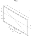
- FIG. 1 is a perspective view showing a display apparatus according to an exemplary embodiment.
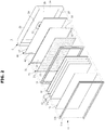
- FIG. 2 is an exploded perspective view showing the display apparatus according to an exemplary embodiment.
- a display apparatus 1 includes a display panel 10 to display image information, and a case 2 to protect the display panel 10 and interior electronic components of the display panel 10 while disposed at an to form the exterior of the display panel 10.
- the display panel 10 may be implemented with a liquid crystal display panel.
- the liquid crystal display panel may include two sheets of glass with a liquid layer injected between a TFT board and a color board, and may also include a driving circuit capable of driving pixels arranged in a matrix to control the light transmission rate of each of the pixels. In this way, an image could be displayed by the LCD panel.
- the case 2 is formed to wrap around borders and a rear surface of the display panel 10 from a rear of the display panel 10.
- the case 2 is provided in the shape of a hexahedron having an open unit 2a at a front surface thereof, and includes a rear surface 2b spaced apart from an open unit 2a, an upper surface 2c connected to an upper side of the rear surface 2b, a lower surface 2d connected to a lower side of the rear surface 2b, and side surfaces 2e each connected to left and right sides of the rear surface 2b.
- a lower portion of the case 2 is provided with a base 3 supported by an installation surface configured to install a bottom of the display apparatus 1.
- the case 2 and the base 3 may be connected to a stand 3a vertically provided at the base 3.
- the display apparatus 1 may be fixed at a wall through a wall-mounting bracket installed at the wall, in place of the stand 3a.
- the wall-mounting bracket may be detachably installed at the case 2, or may be fixed at the wall through the case 2.
- a top chassis 11 is formed in the shape of a rectangular ring, and may include a bezel unit 11a supporting borders of a front surface of the display panel 10, and a top chassis side surface unit 11b installed at a middle mold 14, which is to be described later, extended toward a rear from an outer side end of the bezel unit 11a.
- the middle mold 14 is provided to support the display panel 10.
- the middle mold 14 is provided to be supported at the top chassis side surface unit 11b of the top chassis 11.
- the display panel 10 is provided with a light source 20 provided to radiate light to the display panel 10, a diffusion panel 13 to diffuse the radiated light, and a plurality of optical sheets 12 to improve optical characteristics of the light passed through the diffusion panel 13.
- the optical sheets 12 includes a diffusion sheet 12c to diffuse the light passed through the diffusion panel 13, a prism sheet 12b having a pattern formed by one or more prisms such that the light diffused by the diffusion sheet 12 may be collected in a vertical direction with respect to the display panel 10 positioned in front of the diffusion sheet 12, and a protective sheet 12a provided as to protect the prism sheet 12b sensitive to scratches while disposed at a front of the prism sheet 12b.
- the light source 20 may include a printed circuit board 21 formed in the shape of a plane panel, and a plurality of light-emitting diodes 22 embedded on the printed circuit board 21.
- a light guiding panel may be disposed at a rear side of the display panel and the light-emitting diodes may be disposed at a side of the light guiding panel so that light may be radiated into a side end of the light guiding panel.
- a rear of the display panel 10 is provided with a bottom chassis 30 provided as to accommodate the light source 20.
- the bottom chassis 30 includes a supporting unit 31 formed in the shape of a plane panel such that the light source 20 is accommodated, and an installation unit 32 formed to be installed at the middle mold 14 while forming the four borders of the supporting unit 31.
- the supporting unit 31 of the bottom chassis 30 is provided such that the printed circuit board 21 of the light source 20 may be accommodated thereto. Therefore, the printed circuit board 21 may be formed to correspond to or smaller than the supporting unit 31 of the bottom chassis 30.
- the installation unit 32 of the bottom chassis 30 is provided with an air flowing unit 33 formed thereto as to form a circulative cooling path 100, which is to be described later.
- the air flowing unit 33 may be formed as portions of the both sides of the bottom chassis 30.
- the air flowing unit 33 may be formed as end units of the both left and right sides of the bottom chassis 33, and the air flowing unit 33 formed at the each of the left and right sides may be formed in the corresponding size and shape with respect to each other.
- the air inside the display apparatus 1 may be provided to easily move toward a front and a rear of the bottom chassis 30 through the air flowing units 33.
- the air flowing unit 33 of an exemplary embodiment is illustrated to be formed at each of the both sides of the bottom chassis 30 as an example, but the aspect of the present disclosure is not limited hereto.
- the air flowing unit 33 may be formed at a portion of a bottom chassis supporting unit 31.
- the air flowing unit 33 may be formed lengthways in vertical direction at a predetermined position at each of the left and right sides of the supporting unit.
- a rear of the bottom chassis 30 may be provided with a partition wall 40 disposed while spaced apart by a predetermined distance.
- the partition wall 40 includes a first partition wall 41 corresponding to the supporting unit 31 of the bottom chassis 30, and a second partition wall 42 formed at each of the both sides of the first partition wall 41.
- the second partition wall 42 is provided to be connected to the bottom chassis 30.
- the second partition wall 42 may be connected to the installation unit 32 of the bottom chassis 30.
- the light source 20 installed at the bottom chassis 30 may generate high-temperature heat following radiation.
- the internal of the display apparatus 1 may be cooled due to the heat generated at the light source 20.
- the circulative cooling path 100 is formed between the bottom chassis 30 and the case 2 to have air circulated at the surroundings of the bottom chassis 30 to cool down the display apparatus 1.
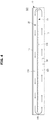
- FIG. 3 is a cross-sectional view of a display apparatus along a line A-A' of FIG. 1 .
- FIG. 4 is a drawing schematically showing a circulative cooling path of a display apparatus according to an exemplary embodiment.
- the circulative cooling path 100 may include a first cooling path 110 provided at a front of the bottom chassis 30, a second cooling path 120 provided at a rear of the bottom chassis 30, and a connecting path 140 connecting the first cooling path 110 and the second cooling path 120.
- the first cooling path 110 is provided at the front of the bottom chassis 30, and is provided to alleviate the heat generated from the printed circuit board 21 and the plurality of light-emitting diodes 22 of the light source 20.
- the first cooling path 110 may be formed between a front surface of the bottom chassis 30 and a rear surface of the display panel 10.
- the rear surface of the display panel 10 may be provided with the plurality of optical sheets 12 and the diffusion panel 13.
- the heat generated from the printed circuit board 21 and the plurality of light-emitting diodes 22 installed on the bottom chassis 30 may be alleviated.
- the second cooling path 120 may be formed in between the partition wall 40 and the case 2 provided in rear of the bottom chassis 30.
- the second cooling path 120 is formed between a rear surface of a first partition wall 41 and an inner side surface 2b' of a rear surface of the case 2.
- first cooling path 110 and the second cooling path 120 may be connected to each other.
- first cooling path 110 and the second cooling path 120 may be connected to each other by the connecting path 140.
- the connecting path 140 may be included at the second cooling path 120 and may be formed between a second partition wall 42 and a side surface 2e' of an inner side of the case 2.
- the connecting path 140 provided to connect the first cooling path 110 and the second cooling path 120 may be formed by the air flowing unit 33 of the bottom chassis 30.
- the connecting path 140 is formed between the second partition wall 42 and the inner side surface 2e' of the case 2, but the aspect of the present disclosure is not limited hereto.
- the connecting path may be included in the second cooling path.
- the partition wall 40 installed at the bottom chassis 30 may form a third cooling path 130 between the partition wall 40 and a rear surface of the bottom chassis 30.
- the third cooling path 130 may be formed by a gap distance I between the bottom chassis 30 and the partition wall 40.
- the third cooling path 130 may be formed between a rear surface of the bottom chassis 30 and a front surface of the first partition wall 41.
- the third cooling path 130 is provided with an upper end and a lower end thereof open, and is provided to connect with the first cooling path 110 and the second cooling path 120, respectively.
- the bottom chassis 30 is provided with a separate partition wall 40 at a rear thereof, and the second cooling path 120 of the circulative cooling path 100 is formed between the partition wall 40 and the case 2, and the aspect of the present disclosure is not limited hereto.
- the second cooling path 120 may be formed between the rear surface of the bottom chassis 30 and the inner surface 2b' of the case 2.
- the air circulating the surroundings of the bottom chassis 30 inside the display apparatus 1 forms a single closed loop. That is, the air may cool down the display apparatus while moving and circulating through the first cooling path 110 formed in front of the bottom chassis 30, the connecting path 140 formed at the side of the bottom chassis 30, the second cooling path 120 formed at the rear of the bottom chassis 30, the connecting path 140 at the other side of the bottom chassis 30, and again the first cooling path 110.
- the optical area may be expanded by use of the circulative cooling path 110.
- the heat conductive and heat radiant areas disposed inside the display apparatus 1 may be accordingly expanded to dissipate the heat.
- the air is circulated through the circulative cooling path 100 and the heat is carried by the air due to a convective effect and then dissipated through the areas to reduce the temperature.
- a blower apparatus 50 may be installed at the inner surface 2b' of the rear surface of the case 2.
- the blower apparatus 50 may include a blower fan 52, and a fan motor 51 provided to drive the blower fan 52.
- the case 2 may be provided with an installation bracket 53 for the blower apparatus 50 to be installed.
- the installation bracket 53 may be installed at a center of the inner surface 2b' of the rear surface of the case 2.
- the installation bracket 53 may be provided with a blower fan accommodation unit 54 formed thereto such that the fan motor 51 and the blower fan 52 may be accommodated.
- the air sealed and circulated inside the display apparatus 1 by use of the circulative cooling path 100 may be provided with enhanced moving speed by use of the blower fan 52, and the temperature reduction may be accelerated.
- blower fan 52 and the fan motor 51 configured to drive the blower fan 52 may be formed in a plurality of units.
- FIG. 5 is an enlarged view of a B portion of FIG. 3 schematically illustrating an internal structure of the circulative cooling path according to an exemplary embodiment.
- a second cooling path 120A of the circulative cooling path 100 is provided between the first partition wall 41 and the inner surface 2b' of the rear surface of the case 2.
- a guide unit 60 may be provided at the first partition wall 41 and the inner surface 2b' of the rear surface of the case 2 as to guide air current.
- the guide unit 60 may be provided to change the direction of the air being inlet to the second cooling path 120.
- the guide unit 60 includes a first guide 61A formed with a first angle ⁇ 1 with respect to the first partition wall 41 and the inner surface 2b' of the rear surface of the case 2.
- a plurality of the first guide 61A are formed on each of the first partition wall 41 and the inner surface 2b' of the rear surface of the case 2.
- the first guide 61A formed at the first partition wall 41 extends toward a center of the second cooling path 120 with the first angle ⁇ 1.
- the first guide 61A formed at the inner side surface 2e of the rear of the case 2 protrudes and extends toward the center of the second cooling path 120 with the first angle ⁇ 1.
- the plurality of the first guide 61A may be disposed to be spaced apart with respect to each other by a predetermined distance.
- the first angle ⁇ 1 may be provided with an approximate degree at 90°.
- the first guide 61A formed at the first partition wall 41 and the first guide 61A formed at the inner side surface 2e of the rear of the case 2 may be alternatively disposed with respect to each other.
- the air being inlet to the second cooling path 120A of the circulative cooling path 100 contacts the first guide 61A inside the second cooling path 120A, and then the moving direction (the arrow shown in FIG. 5 ) of the air is directed by by the first guide 61A, and thus cooling effect may be obtained.
- the first guide 61A formed inside the second cooling path 120A may enhance the cooling effect of air by maximizing the contact surface and flow effect of the air.
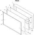
- FIG. 6 is an exploded perspective view schematically showing a display apparatus forming a circulative cooling path according to an exemplary embodiment
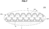
- FIG. 7 is a drawing showing a cooling path of a circulative cooling path according to an exemplary embodiment.
- a circulative cooling path 120B of a display apparatus includes the first cooling path 110 and a second cooling path 120B connected with the first cooling path 110.
- the first cooling path 110 is provided in front of the bottom chassis 30, and the second cooling path 120B is provided in rear of the bottom chassis 30.
- the second cooling path 120B may be formed between the partition wall 40 provided in rear of the bottom chassis 30 and a plate 70 provided in front of the case 2.
- the second cooling path 120 may be formed between a rear surface of the first partition wall 41 and a front surface of the plate 70.
- the plate 70 may have a size corresponding to the rear surface 2b of the case 2 and may be formed in the shape of a panel.
- a guide unit 60B may be provided at the first partition wall 41 and the plate 70 to guide air current.
- the guide unit 60B may be provided to change the direction of the air being inlet to the second cooling path 120B.
- the guide unit 60B includes a second guide 62A formed to be provided with a second angle ⁇ 2 with respect to the first partition wall 41 and a surface of the plate 70.
- a plurality of the second guides 62A are formed on each of the first partition wall 41 and the plate 70.
- the second guide 62A formed on the first partition wall 41 protrudes and extends toward a center of the second cooling path 120B with the second angle ⁇ 2.
- the second guide 62A formed on the plate 70 protrudes and extends toward the center of the second cooling path 120B with the second angle ⁇ 2.
- the plurality of the second guide 62A may be disposed to be spaced apart with respect to each other by a predetermined distance.
- the second angle ⁇ 2 is an obtuse angle between the plate 70/first partition wall 41 and the second guide 62A. From FIG. 7 , it is shown that two adjacent second guides 62A may be connected to form a shape of a triangle toward the center of the second cooling path 120B. Therefore, the air being inlet to the second cooling path 120B of the circulative cooling path 100 i contacts the second guide 62A inside the second cooling path 120B, and then the flowing direction of the air is directed by the second guide 62A, and thus cooling effect may be obtained.
- the second guide 62A formed inside the second cooling path 120B may enhance the cooling effect of air by maximizing the contact surface and flow effect of the air.
- first cooling path 110 and the second cooling path 120B may be connected with each other by use of the connecting path 140.
- the structure of the first cooling path 110 and the connecting path 140 is identical to the above, and redundant descriptions will be omitted.
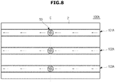
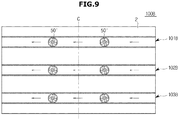
- FIG. 8 to FIG. 12 illustrate drawings showing a plurality of cooling paths according to an exemplary embodiment.
- the circulative cooling path 100A may include a plurality of cooling ducts 101A, 102A, and 103A.
- the plurality of cooling ducts 101A, 102A, and 103A may be provided to form a sealed circulative path while connected with the first cooling path 110 in front of the bottom chassis 30.
- the plurality of cooling ducts 101A, 102A, and 103A may be provided on the inner surface 2b'of the rear surface 2b of the case 2.
- the plurality of cooling ducts 101A, 102A, and 103A may include a first cooling duct 101A formed at an upper side of the case 2, a second cooling duct 102A formed at a center of the case 2, and a third cooling duct 103A formed at a lower side of the case 2.
- the first cooling duct 101A, the second cooling duct 102A, and the third cooling duct 103A are parallelly arranged in a horizontal direction of the case 2.
- the blower apparatus 50E is installed inside each of the plurality of cooling ducts 101A, 102A, and 103A.
- the blower apparatus 50 may be disposed at a center of each of the plurality of cooling ducts 101A, 102A, and 103A.
- each of the plurality of cooling ducts 101A, 102A, and 103A may move due to the blower apparatus 50.
- the circulative cooling path 100B includes a plurality of cooling ducts 101B, 102B, and 103B.
- a plurality of blower apparatuses 50' and 50" may be installed inside each of a plurality of cooling ducts 101B, 102B, and 103B .
- the blower apparatuses 50' and 50" may be installed on an inner side of each of the first cooling duct 101B, the second cooling duct 102B, and the third cooling duct 103B.
- a first blower apparatus 50' and a second blower apparatus 50" may be disposed with a distance from a center C of each of the cooling ducts 101B, 102B, and 103B.
- the circulative cooling path 100C includes a plurality of cooling ducts 101C, 102C, 103C, and 104C, which includes a first cooling duct 101C, a second cooling duct 102C, a third cooling duct 103C formed in a horizontal direction of the case 2, and also includes a fourth cooling duct 104C formed in a vertical direction of the case 2.
- the first cooling duct 101C is formed to be inclined in a lower direction from an upper portion of one side of the case 2 to a lower portion of the other side of the case 2
- the second cooling duct 102C is formed in a horizontal direction from a center of one side of the case 2 to a center of the other side of the case 2
- the third cooling duct 103C is formed to be inclined in an upper direction from a lower portion of one side of the case 2 to an upper portion of the other side of the case 2.
- the fourth cooling duct 104C is disposed at the center C of the case 2, and is formed while vertically extended from a lower end to an upper end.
- the first cooling duct 101C, the second cooling duct 102C, the third cooling duct 103C, and the fourth cooling duct 104C may be connected with each other at the center C of the case 2.
- the blower apparatus 50 may be installed at the center C of the case 2, which is also the center of each of the first cooling duct 101C, the second cooling duct 102C, the third cooling duct 103C, and the fourth cooling duct 104C.
- the air inside each of the first cooling duct 101C, the second cooling duct 102C, the third cooling duct 103C, and the fourth cooling duct 104C may be circulated and moved through the first cooling path 110 by use of the blower apparatus 50.
- the circulative cooling path 100D includes a first cooling duct 101D and a second cooling duct 102D.
- the first cooling duct 101D and the second cooling duct 102D may be provided with the approximate shape of ' ⁇ ' or ' ⁇ ', and may be formed in the vertically bent shapes.
- the first cooling duct 101D extends in a horizontal direction from an end portion of one side of the case 2 to the center C, and is formed in the bent shape from the center toward a lower side.
- the air being inlet through the first cooling path 110 to the first cooling duct 101D may be moved toward a lower side after being inlet through a side direction of the case 2 along the first cooling duct 101D.
- the blower apparatus 50 may be disposed at the bent portion of the first cooling duct 101D.
- the second cooling duct 102D extends in a horizontal direction from an end portion of the other side of the case 2 to the center C, and is formed in the bent shape from the center toward an upper side.
- the air being inlet through the first cooling path 110 to the second cooling duct 102D may be moved toward an upper side after being inlet through a side direction of the case 2 along the second cooling duct 102D.
- the blower apparatus 50 may be disposed at the bent portion of the second cooling duct 102D.
- the circulative cooling path 100E includes a first cooling duct 101E and a second cooling duct 102E.
- the first cooling duct 101E and the second cooling duct 102E may be provided with the approximate shape of ' ⁇ ' or ' ⁇ '.
- the first cooling duct 101E extends in a horizontal direction from an end portion of one side of the case 2 to the center C, and is formed in the vertically extended shape toward an upper side and a lower side from the center.
- the air being inlet through the first cooling path 110 to the first cooling duct 101E may be moved toward an upper side or a lower side after being inlet through a side direction of the case 2 along the first cooling duct 101E, or the air being inlet through a lower side may be moved toward an upper side or a side direction.
- the blower apparatus 50 is disposed at a center of the first cooling duct 101E.
- the second cooling duct 102E extends in a horizontal direction from an end portion of the other side of the case 2 to the center C, and is formed in the vertically extended shape toward an upper side and a lower side from the center.
- the air being inlet through the first cooling path 110 to the second cooling duct 102E may be moved toward an upper side or a lower side after being inlet through a side direction of the case 2 along the second cooling duct 102E.
- the air being inlet into the second cooling duct 102E may be moved toward an upper side or a side direction.
- blower apparatus 50 is disposed at a center of the first cooling duct 102E.
Description
- Apparatuses consistent with exemplary embodiments relate to a display apparatus, and more particularly, to a display apparatus capable of enhancing cooling efficiency.
- In general, a display apparatus is an apparatus, such as a TV or a monitor, capable of displaying images.
- The display apparatus may be classified into several categories according to different display mechanisms. For example, a display apparatus could be liquid crystal display (LCD) or a plasma display panel (PDP), which are largely used.
- An LCD is provided with a liquid crystal display panel, which is not capable of self-radiating lights, and thus includes a backlight assembly to generate light for the LCD panel.
- The backlight assembly includes a light source to generate light, optical members to enhance efficiency of the light, and a bottom chassis to accommodate the light source and the optical members.
- Meanwhile, the high-temperature heat generated from the light source may increase the internal temperature of the backlight assembly, and an acceleration of heating may occur due to the increased internal heat.
US 2014/085866 A1 ,WO 2013/182733 A1 ,US 2012/320566 A1 ,WO 2012/026175 A1 show display devices with air circulation means. - Therefore, aspects of the exemplary embodiments provide a display apparatus including a cooling path provided to enhance cooling efficiency.
- Additional aspect of the exemplary embodiments provide a display apparatus provided to be isolated from outside environment while having a sealed cooling structure configured not to inlet outside air. Additional aspects of the exemplary embodiments provide a display apparatus capable of enhancing durability through diffusing heat and reducing temperature of an internal of a backlight unit
- Additional aspects of the exemplary embodiments will be set forth in part in the description which follows and, in part, will be obvious from the description, or may be learned by practice of the disclosure.
- In accordance with one aspect of the exemplary embodiments, this is provided a display apparatus as set forth in the claims. The display apparatus includes a display panel configured to display images; a light source configured to emit light to the display panel; a bottom chassis disposed in rear of the light source; a case provided in rear of the bottom chassis; a circulative cooling path forming a single closed loop around the bottom chassis that is configured to have air circulated at the sides, front and rear of the bottom chassis while provided in between of the bottom chassis and the case; and a blower apparatus configured to drive the air to circulate through the circulative cooling path.
- In addition, the circulative cooling path may include a first cooling path positioned in front of the bottom chassis, and a second cooling path provided between a rear surface of the bottom chassis and a front surface of the case.
- In addition, the first cooling path and the second cooling path may be connected with each other.
- In addition, the bottom chassis may be provided with an air flowing unit formed thereto to connect the first cooling path with the circulative cooling path.
- In addition, the display apparatus may include a partition wall spaced apart toward a rear of the bottom chassis, and wherein the second cooling path may comprises an outer cooling path formed between the partition wall and the case and an inner cooling path may be formed between a rear surface of the bottom chassis and the partition wall.
- In addition, the circulative cooling path may include at least one cooling path, and the blower apparatus may be disposed inside the cooling path.
- In addition, the second cooling path may include a guide unit provided to guide air current.
- In addition, the guide unit may include a first guide rib formed with a first angle.
- In addition, the first angle may be about 90°.
- In addition, the guide unit may include a second guide formed with a second angle.
- In addition, the second angle may be an obtuse angle, and the second guide unit comprises a plurality of second guides connected with each other
- The blower apparatus may include a blower fan, and a fan motor to drive the blower fan.
- In accordance with an example, this is provided a display apparatus including a case; a display panel installed inside the case; a light source provided as to radiate light to the display panel; a bottom chassis configured to support the light source; and a circulative cooling path to cool the display panel and the light source inside the case, and the circulative cooling path may include a first cooling path provided at a front of the bottom chassis, and a second cooling path provided in between a rear surface of the bottom chassis and a front surface of the case, and the first cooling path and the second cooling path may be connected with each other.
- In addition, the display apparatus may further include a blower apparatus having a blower fan to circulate air through the circulative cooling path, and a fan motor provided to drive the blower fan.
- In addition, the bottom chassis may be provided with an air flowing unit formed thereto to connect the first cooling path with the circulative cooling path.
- In addition, the air flowing unit may be formed on at least one side of the bottom chassis is open.
- In addition, the bottom chassis may include a partition wall provided while being spaced apart toward a rear thereof, and the second cooling path may be formed between the partition wall and the case.
- In addition, a third cooling path may be formed between a rear surface of the bottom chassis and the partition wall.
- In addition, the circulative cooling path may include at least one cooling duct, and the blower apparatus may be disposed inside the cooling duct.
- In addition, the second cooling path may include a guide unit provided as to guide an air current.
- In addition, the guide unit may include a first guide formed t with a first angle with respect to the partition wall.
- In addition, the first angle is about 90°.
- In addition, the guide unit may include a second guide formed with a second angle with respect to the partition wall.
- In addition, the second angle may be an obtuse angle, and a plurality of the second guide may be provided by connecting with each other.
- These and/or other aspects of the disclosure will become apparent and more readily appreciated from the following description of the embodiments, taken in conjunction with the accompanying drawings of which:
-
FIG. 1 illustrates a perspective view showing a display apparatus according to an exemplary embodiment. -
FIG. 2 illustrates an exploded perspective view showing the display apparatus according to an exemplary embodiment. -
FIG. 3 illustrates a cross-sectional view of a display apparatus along a line A-A' ofFIG. 1 . -
FIG. 4 illustrates a drawing schematically showing a circulative cooling path of a display apparatus according to an exemplary embodiment. -
FIG. 5 illustrates an enlarged view of a B portion ofFIG. 3 schematically illustrating an internal structure of the circulative cooling path according to an exemplary embodiment. -
FIG. 6 illustrates an exploded perspective view schematically showing a display apparatus forming a circulative cooling path according to an exemplary embodiment. -
FIG. 7 illustrates a drawing showing a cooling path of a circulative cooling path according to an exemplary embodiment. -
FIGS. 8 to 12 illustrate drawings showing a plurality of cooling paths according to an exemplary embodiment. - Reference will now be made in detail to the embodiments of the present disclosure, examples of which are illustrated in the accompanying drawings, wherein like reference numerals refer to like elements throughout. Meanwhile, terminologies such as "a front end," "a rear end," "an upper portion," "a lower portion," "an upper end," and "a lower end" used in descriptions below are defined while having the drawings as references, and the shapes and positions of each component of the present disclosure are not limited to the terminologies as such.
-
FIG. 1 is a perspective view showing a display apparatus according to an exemplary embodiment.FIG. 2 is an exploded perspective view showing the display apparatus according to an exemplary embodiment. As illustrated onFIG. 1 andFIG. 2 , adisplay apparatus 1 includes adisplay panel 10 to display image information, and acase 2 to protect thedisplay panel 10 and interior electronic components of thedisplay panel 10 while disposed at an to form the exterior of thedisplay panel 10. - The
display panel 10 may be implemented with a liquid crystal display panel. Generally, the liquid crystal display panel may include two sheets of glass with a liquid layer injected between a TFT board and a color board, and may also include a driving circuit capable of driving pixels arranged in a matrix to control the light transmission rate of each of the pixels. In this way, an image could be displayed by the LCD panel. - The
case 2 is formed to wrap around borders and a rear surface of thedisplay panel 10 from a rear of thedisplay panel 10. Thecase 2 is provided in the shape of a hexahedron having anopen unit 2a at a front surface thereof, and includes arear surface 2b spaced apart from anopen unit 2a, an upper surface 2c connected to an upper side of therear surface 2b, alower surface 2d connected to a lower side of therear surface 2b, andside surfaces 2e each connected to left and right sides of therear surface 2b. - A lower portion of the
case 2 is provided with abase 3 supported by an installation surface configured to install a bottom of thedisplay apparatus 1. Thecase 2 and thebase 3 may be connected to astand 3a vertically provided at thebase 3. - The
display apparatus 1 may be fixed at a wall through a wall-mounting bracket installed at the wall, in place of thestand 3a. In this case, the wall-mounting bracket may be detachably installed at thecase 2, or may be fixed at the wall through thecase 2. - A
top chassis 11 is formed in the shape of a rectangular ring, and may include abezel unit 11a supporting borders of a front surface of thedisplay panel 10, and a top chassisside surface unit 11b installed at amiddle mold 14, which is to be described later, extended toward a rear from an outer side end of thebezel unit 11a. - The
middle mold 14 is provided to support thedisplay panel 10. Themiddle mold 14 is provided to be supported at the top chassisside surface unit 11b of thetop chassis 11. - The
display panel 10 is provided with alight source 20 provided to radiate light to thedisplay panel 10, adiffusion panel 13 to diffuse the radiated light, and a plurality ofoptical sheets 12 to improve optical characteristics of the light passed through thediffusion panel 13. - The
optical sheets 12 includes a diffusion sheet 12c to diffuse the light passed through thediffusion panel 13, aprism sheet 12b having a pattern formed by one or more prisms such that the light diffused by thediffusion sheet 12 may be collected in a vertical direction with respect to thedisplay panel 10 positioned in front of thediffusion sheet 12, and aprotective sheet 12a provided as to protect theprism sheet 12b sensitive to scratches while disposed at a front of theprism sheet 12b. - The
light source 20 may include a printedcircuit board 21 formed in the shape of a plane panel, and a plurality of light-emittingdiodes 22 embedded on the printedcircuit board 21. - Meanwhile, in an exemplary embodiment, an example in which the plurality of light-emitting
diodes 22 is provided to directly radiate light to thedisplay panel 10 while installed behind thedisplay panel 10 is illustrated, but the aspect of the present disclosure is not limited hereto. For example, a light guiding panel may be disposed at a rear side of the display panel and the light-emitting diodes may be disposed at a side of the light guiding panel so that light may be radiated into a side end of the light guiding panel. - A rear of the
display panel 10 is provided with abottom chassis 30 provided as to accommodate thelight source 20. - The
bottom chassis 30 includes a supportingunit 31 formed in the shape of a plane panel such that thelight source 20 is accommodated, and aninstallation unit 32 formed to be installed at themiddle mold 14 while forming the four borders of the supportingunit 31. - The supporting
unit 31 of thebottom chassis 30 is provided such that the printedcircuit board 21 of thelight source 20 may be accommodated thereto. Therefore, the printedcircuit board 21 may be formed to correspond to or smaller than the supportingunit 31 of thebottom chassis 30. - The
installation unit 32 of thebottom chassis 30 is provided with anair flowing unit 33 formed thereto as to form acirculative cooling path 100, which is to be described later. Theair flowing unit 33 may be formed as portions of the both sides of thebottom chassis 30. - The
air flowing unit 33 may be formed as end units of the both left and right sides of thebottom chassis 33, and theair flowing unit 33 formed at the each of the left and right sides may be formed in the corresponding size and shape with respect to each other. The air inside thedisplay apparatus 1 may be provided to easily move toward a front and a rear of thebottom chassis 30 through theair flowing units 33. - The
air flowing unit 33 of an exemplary embodiment is illustrated to be formed at each of the both sides of thebottom chassis 30 as an example, but the aspect of the present disclosure is not limited hereto. For example, theair flowing unit 33 may be formed at a portion of a bottomchassis supporting unit 31. In this case, theair flowing unit 33 may be formed lengthways in vertical direction at a predetermined position at each of the left and right sides of the supporting unit. - Meanwhile, a rear of the
bottom chassis 30 may be provided with apartition wall 40 disposed while spaced apart by a predetermined distance. Thepartition wall 40 includes afirst partition wall 41 corresponding to the supportingunit 31 of thebottom chassis 30, and asecond partition wall 42 formed at each of the both sides of thefirst partition wall 41. - The
second partition wall 42 is provided to be connected to thebottom chassis 30. Thesecond partition wall 42 may be connected to theinstallation unit 32 of thebottom chassis 30. - Meanwhile, the
light source 20 installed at thebottom chassis 30 may generate high-temperature heat following radiation. The internal of thedisplay apparatus 1 may be cooled due to the heat generated at thelight source 20. - The
circulative cooling path 100 is formed between thebottom chassis 30 and thecase 2 to have air circulated at the surroundings of thebottom chassis 30 to cool down thedisplay apparatus 1. -
FIG. 3 is a cross-sectional view of a display apparatus along a line A-A' ofFIG. 1 .FIG. 4 is a drawing schematically showing a circulative cooling path of a display apparatus according to an exemplary embodiment. As illustrated onFIG. 3 andFIG. 4 , thecirculative cooling path 100 may include afirst cooling path 110 provided at a front of thebottom chassis 30, asecond cooling path 120 provided at a rear of thebottom chassis 30, and a connectingpath 140 connecting thefirst cooling path 110 and thesecond cooling path 120. - The
first cooling path 110 is provided at the front of thebottom chassis 30, and is provided to alleviate the heat generated from the printedcircuit board 21 and the plurality of light-emittingdiodes 22 of thelight source 20. - The
first cooling path 110 may be formed between a front surface of thebottom chassis 30 and a rear surface of thedisplay panel 10. In this case, , the rear surface of thedisplay panel 10 may be provided with the plurality ofoptical sheets 12 and thediffusion panel 13. - Therefore, the heat generated from the printed
circuit board 21 and the plurality of light-emittingdiodes 22 installed on thebottom chassis 30 may be alleviated. - The
second cooling path 120 may be formed in between thepartition wall 40 and thecase 2 provided in rear of thebottom chassis 30. Thesecond cooling path 120 is formed between a rear surface of afirst partition wall 41 and aninner side surface 2b' of a rear surface of thecase 2. - In this case, the
first cooling path 110 and thesecond cooling path 120 may be connected to each other. For example, thefirst cooling path 110 and thesecond cooling path 120 may be connected to each other by the connectingpath 140. The connectingpath 140 may be included at thesecond cooling path 120 and may be formed between asecond partition wall 42 and aside surface 2e' of an inner side of thecase 2. - The connecting
path 140 provided to connect thefirst cooling path 110 and thesecond cooling path 120 may be formed by theair flowing unit 33 of thebottom chassis 30. In an exemplary embodiment, the connectingpath 140 is formed between thesecond partition wall 42 and theinner side surface 2e' of thecase 2, but the aspect of the present disclosure is not limited hereto. For example, the connecting path may be included in the second cooling path. - In addition, the
partition wall 40 installed at thebottom chassis 30 may form athird cooling path 130 between thepartition wall 40 and a rear surface of thebottom chassis 30. Thethird cooling path 130 may be formed by a gap distance I between thebottom chassis 30 and thepartition wall 40. Thethird cooling path 130 may be formed between a rear surface of thebottom chassis 30 and a front surface of thefirst partition wall 41. Thethird cooling path 130 is provided with an upper end and a lower end thereof open, and is provided to connect with thefirst cooling path 110 and thesecond cooling path 120, respectively. - Meanwhile, in an exemplary embodiment, the
bottom chassis 30 is provided with aseparate partition wall 40 at a rear thereof, and thesecond cooling path 120 of thecirculative cooling path 100 is formed between thepartition wall 40 and thecase 2, and the aspect of the present disclosure is not limited hereto. For example, thesecond cooling path 120 may be formed between the rear surface of thebottom chassis 30 and theinner surface 2b' of thecase 2. - By use of the structure, the air circulating the surroundings of the
bottom chassis 30 inside thedisplay apparatus 1 forms a single closed loop. That is, the air may cool down the display apparatus while moving and circulating through thefirst cooling path 110 formed in front of thebottom chassis 30, the connectingpath 140 formed at the side of thebottom chassis 30, thesecond cooling path 120 formed at the rear of thebottom chassis 30, the connectingpath 140 at the other side of thebottom chassis 30, and again thefirst cooling path 110. - In addition, the optical area may be expanded by use of the
circulative cooling path 110. For example, the heat conductive and heat radiant areas disposed inside thedisplay apparatus 1 may be accordingly expanded to dissipate the heat. For example, the air is circulated through thecirculative cooling path 100 and the heat is carried by the air due to a convective effect and then dissipated through the areas to reduce the temperature. - In this case, a
blower apparatus 50 may be installed at theinner surface 2b' of the rear surface of thecase 2. Theblower apparatus 50 may include a blower fan 52, and a fan motor 51 provided to drive the blower fan 52. - The
case 2 may be provided with aninstallation bracket 53 for theblower apparatus 50 to be installed. Theinstallation bracket 53 may be installed at a center of theinner surface 2b' of the rear surface of thecase 2. Theinstallation bracket 53 may be provided with a blower fan accommodation unit 54 formed thereto such that the fan motor 51 and the blower fan 52 may be accommodated. - Meanwhile, the air sealed and circulated inside the
display apparatus 1 by use of thecirculative cooling path 100 may be provided with enhanced moving speed by use of the blower fan 52, and the temperature reduction may be accelerated. - At this time, the blower fan 52 and the fan motor 51 configured to drive the blower fan 52 may be formed in a plurality of units.
-
FIG. 5 is an enlarged view of a B portion ofFIG. 3 schematically illustrating an internal structure of the circulative cooling path according to an exemplary embodiment. - As illustrated on
FIG. 5 , asecond cooling path 120A of thecirculative cooling path 100 is provided between thefirst partition wall 41 and theinner surface 2b' of the rear surface of thecase 2. - At this time, a
guide unit 60 may be provided at thefirst partition wall 41 and theinner surface 2b' of the rear surface of thecase 2 as to guide air current. - The
guide unit 60 may be provided to change the direction of the air being inlet to thesecond cooling path 120. Theguide unit 60 includes afirst guide 61A formed with a first angle θ1 with respect to thefirst partition wall 41 and theinner surface 2b' of the rear surface of thecase 2. - A plurality of the
first guide 61A are formed on each of thefirst partition wall 41 and theinner surface 2b' of the rear surface of thecase 2. - The
first guide 61A formed at thefirst partition wall 41 extends toward a center of thesecond cooling path 120 with the first angle θ1. Thefirst guide 61A formed at theinner side surface 2e of the rear of thecase 2 protrudes and extends toward the center of thesecond cooling path 120 with the first angle θ1. The plurality of thefirst guide 61A may be disposed to be spaced apart with respect to each other by a predetermined distance. - In this case, the first angle θ1 may be provided with an approximate degree at 90°.
- The
first guide 61A formed at thefirst partition wall 41 and thefirst guide 61A formed at theinner side surface 2e of the rear of thecase 2 may be alternatively disposed with respect to each other. - Meanwhile, the air being inlet to the
second cooling path 120A of thecirculative cooling path 100 contacts thefirst guide 61A inside thesecond cooling path 120A, and then the moving direction (the arrow shown inFIG. 5 ) of the air is directed by by thefirst guide 61A, and thus cooling effect may be obtained. - The
first guide 61A formed inside thesecond cooling path 120A may enhance the cooling effect of air by maximizing the contact surface and flow effect of the air. -
FIG. 6 is an exploded perspective view schematically showing a display apparatus forming a circulative cooling path according to an exemplary embodiment, andFIG. 7 is a drawing showing a cooling path of a circulative cooling path according to an exemplary embodiment. - As illustrated on
FIG. 6 andFIG. 7 , acirculative cooling path 120B of a display apparatus according to an exemplary embodiment includes thefirst cooling path 110 and asecond cooling path 120B connected with thefirst cooling path 110. - The
first cooling path 110 is provided in front of thebottom chassis 30, and thesecond cooling path 120B is provided in rear of thebottom chassis 30. - The
second cooling path 120B may be formed between thepartition wall 40 provided in rear of thebottom chassis 30 and aplate 70 provided in front of thecase 2. Thesecond cooling path 120 may be formed between a rear surface of thefirst partition wall 41 and a front surface of theplate 70. - The
plate 70 may have a size corresponding to therear surface 2b of thecase 2 and may be formed in the shape of a panel. - In this case, a
guide unit 60B may be provided at thefirst partition wall 41 and theplate 70 to guide air current. Theguide unit 60B may be provided to change the direction of the air being inlet to thesecond cooling path 120B. Theguide unit 60B includes asecond guide 62A formed to be provided with a second angle θ2 with respect to thefirst partition wall 41 and a surface of theplate 70. - A plurality of the
second guides 62A are formed on each of thefirst partition wall 41 and theplate 70. Thesecond guide 62A formed on thefirst partition wall 41 protrudes and extends toward a center of thesecond cooling path 120B with the second angle θ2. Thesecond guide 62A formed on theplate 70 protrudes and extends toward the center of thesecond cooling path 120B with the second angle θ2. The plurality of thesecond guide 62A may be disposed to be spaced apart with respect to each other by a predetermined distance. - In this case, the second angle θ2 is an obtuse angle between the
plate 70/first partition wall 41 and thesecond guide 62A. FromFIG. 7 , it is shown that two adjacentsecond guides 62A may be connected to form a shape of a triangle toward the center of thesecond cooling path 120B. Therefore, the air being inlet to thesecond cooling path 120B of the circulative cooling path 100 i contacts thesecond guide 62A inside thesecond cooling path 120B, and then the flowing direction of the air is directed by thesecond guide 62A, and thus cooling effect may be obtained. - The
second guide 62A formed inside thesecond cooling path 120B may enhance the cooling effect of air by maximizing the contact surface and flow effect of the air. - Meanwhile, the
first cooling path 110 and thesecond cooling path 120B may be connected with each other by use of the connectingpath 140. The structure of thefirst cooling path 110 and the connectingpath 140 is identical to the above, and redundant descriptions will be omitted. -
FIG. 8 to FIG. 12 illustrate drawings showing a plurality of cooling paths according to an exemplary embodiment. - As illustrated on
FIG. 8 andFIG. 9 , thecirculative cooling path 100A may include a plurality ofcooling ducts - The plurality of
cooling ducts first cooling path 110 in front of thebottom chassis 30. - The plurality of
cooling ducts rear surface 2b of thecase 2. - The plurality of
cooling ducts first cooling duct 101A formed at an upper side of thecase 2, asecond cooling duct 102A formed at a center of thecase 2, and athird cooling duct 103A formed at a lower side of thecase 2. - The
first cooling duct 101A, thesecond cooling duct 102A, and thethird cooling duct 103A are parallelly arranged in a horizontal direction of thecase 2. The blower apparatus 50E is installed inside each of the plurality ofcooling ducts blower apparatus 50 may be disposed at a center of each of the plurality ofcooling ducts - Therefore, the air inside each of the plurality of
cooling ducts blower apparatus 50. - In addition, the
circulative cooling path 100B includes a plurality of coolingducts blower apparatuses 50' and 50" may be installed inside each of a plurality of coolingducts - The blower apparatuses 50' and 50" may be installed on an inner side of each of the
first cooling duct 101B, thesecond cooling duct 102B, and thethird cooling duct 103B. A first blower apparatus 50' and asecond blower apparatus 50" may be disposed with a distance from a center C of each of the coolingducts - As illustrated on
FIG. 10 , the circulative cooling path 100C includes a plurality of coolingducts 101C, 102C, 103C, and 104C, which includes a first cooling duct 101C, a second cooling duct 102C, a third cooling duct 103C formed in a horizontal direction of thecase 2, and also includes afourth cooling duct 104C formed in a vertical direction of thecase 2. - The first cooling duct 101C is formed to be inclined in a lower direction from an upper portion of one side of the
case 2 to a lower portion of the other side of thecase 2, the second cooling duct 102C is formed in a horizontal direction from a center of one side of thecase 2 to a center of the other side of thecase 2, and the third cooling duct 103C is formed to be inclined in an upper direction from a lower portion of one side of thecase 2 to an upper portion of the other side of thecase 2. - The
fourth cooling duct 104C is disposed at the center C of thecase 2, and is formed while vertically extended from a lower end to an upper end. - At this time, the first cooling duct 101C, the second cooling duct 102C, the third cooling duct 103C, and the
fourth cooling duct 104C may be connected with each other at the center C of thecase 2. Theblower apparatus 50 may be installed at the center C of thecase 2, which is also the center of each of the first cooling duct 101C, the second cooling duct 102C, the third cooling duct 103C, and thefourth cooling duct 104C. - Therefore, the air inside each of the first cooling duct 101C, the second cooling duct 102C, the third cooling duct 103C, and the
fourth cooling duct 104C may be circulated and moved through thefirst cooling path 110 by use of theblower apparatus 50. - As illustrated on
FIG. 11 , the circulative cooling path 100D includes a first cooling duct 101D and a second cooling duct 102D. - The first cooling duct 101D and the second cooling duct 102D may be provided with the approximate shape of '¬' or '└', and may be formed in the vertically bent shapes. The first cooling duct 101D extends in a horizontal direction from an end portion of one side of the
case 2 to the center C, and is formed in the bent shape from the center toward a lower side. - Therefore, the air being inlet through the
first cooling path 110 to the first cooling duct 101D may be moved toward a lower side after being inlet through a side direction of thecase 2 along the first cooling duct 101D. In this case, theblower apparatus 50 may be disposed at the bent portion of the first cooling duct 101D. - In addition, the second cooling duct 102D extends in a horizontal direction from an end portion of the other side of the
case 2 to the center C, and is formed in the bent shape from the center toward an upper side. - Therefore, the air being inlet through the
first cooling path 110 to the second cooling duct 102D may be moved toward an upper side after being inlet through a side direction of thecase 2 along the second cooling duct 102D. In this case, theblower apparatus 50 may be disposed at the bent portion of the second cooling duct 102D. - As illustrated on
FIG. 12 , thecirculative cooling path 100E includes afirst cooling duct 101E and asecond cooling duct 102E. - The
first cooling duct 101E and thesecond cooling duct 102E may be provided with the approximate shape of '├' or '┤'. - The
first cooling duct 101E extends in a horizontal direction from an end portion of one side of thecase 2 to the center C, and is formed in the vertically extended shape toward an upper side and a lower side from the center. - Therefore, the air being inlet through the
first cooling path 110 to thefirst cooling duct 101E may be moved toward an upper side or a lower side after being inlet through a side direction of thecase 2 along thefirst cooling duct 101E, or the air being inlet through a lower side may be moved toward an upper side or a side direction. - In this case, the
blower apparatus 50 is disposed at a center of thefirst cooling duct 101E. - In addition, the
second cooling duct 102E extends in a horizontal direction from an end portion of the other side of thecase 2 to the center C, and is formed in the vertically extended shape toward an upper side and a lower side from the center. - Therefore, the air being inlet through the
first cooling path 110 to thesecond cooling duct 102E may be moved toward an upper side or a lower side after being inlet through a side direction of thecase 2 along thesecond cooling duct 102E. - Or, the air being inlet into the
second cooling duct 102E may be moved toward an upper side or a side direction. - Similarly, the
blower apparatus 50 is disposed at a center of thefirst cooling duct 102E. - Although a few embodiments of the present disclosure have been shown and described, it would be appreciated by those skilled in the art that changes may be made in these embodiments without departing from the scope of the invention which is defined in the claims.
Claims (12)
- A display apparatus (1), comprising:a display panel (10) at which images are displayed;a light source (22) configured to radiate light at the display panel;a bottom chassis (30) disposed at a rear of the light source; anda case (2) provided at a rear of the bottom chassis;characterised in that:the display apparatus comprises a circulative cooling path (100) forming a single closed loop around the bottom chassis that is configured to have air circulated at the sides, front and rear of the bottom chassis while provided in between of the bottom chassis and the case; anda blower apparatus (50) to have the air circulated through the circulative cooling path.
- The display apparatus (1) of claim 1, wherein
the circulative cooling path (100) comprises:a first cooling path (110) positioned at a front of the bottom chassis (30), anda second cooling path (120, 120A, 120B) provided in between of a rear surface of the bottom chassis and a front surface of the case (2) while positioned at a rear of the bottom chassis. - The display apparatus (1) of claim 2, wherein:
the first cooling path (110) and the second circulative path (120, 120A, 120B) are connected with each other. - The display apparatus (1) of claim 2, wherein: the bottom chassis (30) is provided with an air flowing unit (33) formed thereto to connect the first cooling path (110) with the second cooling path (120, 120A, 120B).
- The display apparatus (1) of claim 2, comprising:a partition wall (40) provided while being spaced apart toward a rear of the bottom chassis (30), andwherein the second cooling path comprises:an outer cooling path (120, 120A, 120B) formed between the partition wall and the case (2); andan inner cooling path (130) formed between a rear surface of the bottom chassis (30) and the partition wall (40).
- The display apparatus (1) of claim 1, wherein: the circulative cooling path (100) comprises at least one cooling path, and the blower apparatus (50) is disposed at an inside of the cooling path.
- The display apparatus (1) of claim 2, wherein:
the second cooling path (120, 120A, 120B) comprises a guide unit (60) to guide air current. - The display apparatus (1) of claim 7, wherein:
the guide unit (60) comprises a first guide (61A) formed with a first angle (θ1). - The display apparatus (1) of claim 8, wherein:
the first angle (θ1) is substantially equal to 90°. - The display apparatus (1) of claim 7, wherein:
the guide unit (60B) comprises a second guide (62A) formed with a second angle (θ2). - The display apparatus (1) of claim 10, wherein:
the second angle (θ2) is an obtuse angle, and the second guide (60B) is provided by connecting at least one guide rib to each other. - The display apparatus (1) of claim 1, wherein:
the blower apparatus (50) comprises:a blower fan (52); anda fan motor (51) to drive the blower fan.
Applications Claiming Priority (1)
| Application Number | Priority Date | Filing Date | Title |
|---|---|---|---|
| KR1020150035190A KR102305840B1 (en) | 2015-03-13 | 2015-03-13 | Display apparatus |
Publications (2)
| Publication Number | Publication Date |
|---|---|
| EP3067739A1 EP3067739A1 (en) | 2016-09-14 |
| EP3067739B1 true EP3067739B1 (en) | 2018-06-13 |
Family
ID=55521562
Family Applications (1)
| Application Number | Title | Priority Date | Filing Date |
|---|---|---|---|
| EP16159042.7A Not-in-force EP3067739B1 (en) | 2015-03-13 | 2016-03-07 | Display apparatus |
Country Status (4)
| Country | Link |
|---|---|
| US (1) | US9851089B2 (en) |
| EP (1) | EP3067739B1 (en) |
| KR (1) | KR102305840B1 (en) |
| CN (1) | CN105974662B (en) |
Families Citing this family (21)
| Publication number | Priority date | Publication date | Assignee | Title |
|---|---|---|---|---|
| US8654302B2 (en) | 2008-03-03 | 2014-02-18 | Manufacturing Resources International, Inc. | Heat exchanger for an electronic display |
| US10827656B2 (en) | 2008-12-18 | 2020-11-03 | Manufacturing Resources International, Inc. | System for cooling an electronic image assembly with circulating gas and ambient gas |
| US10194564B2 (en) | 2014-04-30 | 2019-01-29 | Manufacturing Resources International, Inc. | Back to back electronic display assembly |
| JP2018049233A (en) * | 2016-09-23 | 2018-03-29 | パナソニック液晶ディスプレイ株式会社 | Liquid crystal display device |
| KR102258444B1 (en) * | 2017-03-13 | 2021-05-31 | 엘지전자 주식회사 | Display device |
| US10485113B2 (en) | 2017-04-27 | 2019-11-19 | Manufacturing Resources International, Inc. | Field serviceable and replaceable display |
| EP3616481A4 (en) * | 2017-04-27 | 2020-12-23 | Manufacturing Resources International, Inc. | System and method for preventing display bowing |
| CN109031774B (en) * | 2017-06-12 | 2021-06-11 | 群创光电股份有限公司 | Display device |
| US10602626B2 (en) | 2018-07-30 | 2020-03-24 | Manufacturing Resources International, Inc. | Housing assembly for an integrated display unit |
| US11096317B2 (en) | 2019-02-26 | 2021-08-17 | Manufacturing Resources International, Inc. | Display assembly with loopback cooling |
| US10795413B1 (en) | 2019-04-03 | 2020-10-06 | Manufacturing Resources International, Inc. | Electronic display assembly with a channel for ambient air in an access panel |
| KR20220148221A (en) * | 2020-02-24 | 2022-11-04 | 엘지전자 주식회사 | display device |
| USD958246S1 (en) * | 2020-03-11 | 2022-07-19 | Ambow Sihua Intelligent Technology Co., Ltd. | Vertical display device |
| US11477923B2 (en) | 2020-10-02 | 2022-10-18 | Manufacturing Resources International, Inc. | Field customizable airflow system for a communications box |
| US11470749B2 (en) | 2020-10-23 | 2022-10-11 | Manufacturing Resources International, Inc. | Forced air cooling for display assemblies using centrifugal fans |
| US11778757B2 (en) | 2020-10-23 | 2023-10-03 | Manufacturing Resources International, Inc. | Display assemblies incorporating electric vehicle charging equipment |
| US11966263B2 (en) | 2021-07-28 | 2024-04-23 | Manufacturing Resources International, Inc. | Display assemblies for providing compressive forces at electronic display layers |
| US11744054B2 (en) | 2021-08-23 | 2023-08-29 | Manufacturing Resources International, Inc. | Fan unit for providing improved airflow within display assemblies |
| US11919393B2 (en) | 2021-08-23 | 2024-03-05 | Manufacturing Resources International, Inc. | Display assemblies inducing relatively turbulent flow and integrating electric vehicle charging equipment |
| US11762231B2 (en) | 2021-08-23 | 2023-09-19 | Manufacturing Resources International, Inc. | Display assemblies inducing turbulent flow |
| US11968813B2 (en) | 2021-11-23 | 2024-04-23 | Manufacturing Resources International, Inc. | Display assembly with divided interior space |
Family Cites Families (12)
| Publication number | Priority date | Publication date | Assignee | Title |
|---|---|---|---|---|
| JP2001326488A (en) * | 2000-05-16 | 2001-11-22 | Canon Inc | Electronic equipment |
| KR100638047B1 (en) * | 2004-10-15 | 2006-10-23 | 엘지전자 주식회사 | Liquid crystal display having back light unit |
| KR20060081467A (en) * | 2005-01-07 | 2006-07-13 | 삼성전자주식회사 | Liquid crystal display device |
| US20080108439A1 (en) | 2006-11-07 | 2008-05-08 | Cole Joseph W | Cooling configuration for gaming machine display |
| KR101456975B1 (en) | 2007-09-27 | 2014-10-31 | 삼성전자 주식회사 | Cooling unit and display apparatus having the same |
| KR101418585B1 (en) | 2007-12-10 | 2014-07-16 | 삼성디스플레이 주식회사 | Backlight assemby, display apparatus having the same and method for assembling the same |
| KR100920827B1 (en) * | 2008-12-19 | 2009-10-08 | (주)이젤 | Coling system of lcd device |
| WO2010110022A1 (en) * | 2009-03-25 | 2010-09-30 | シャープ株式会社 | Backlight structure |
| WO2011104953A1 (en) * | 2010-02-25 | 2011-09-01 | シャープ株式会社 | Liquid-crystal display device and led backlight unit |
| WO2012026175A1 (en) * | 2010-08-24 | 2012-03-01 | シャープ株式会社 | Light emitting device, display device and television reception device |
| US9046255B2 (en) * | 2011-05-18 | 2015-06-02 | Sharp Kabushiki Kaisha | Illumination device and display device |
| WO2013182733A1 (en) * | 2012-06-08 | 2013-12-12 | Mitron Oy | Information display and a method for cooling an information display |
-
2015
- 2015-03-13 KR KR1020150035190A patent/KR102305840B1/en active IP Right Grant
-
2016
- 2016-03-07 EP EP16159042.7A patent/EP3067739B1/en not_active Not-in-force
- 2016-03-11 US US15/067,703 patent/US9851089B2/en active Active
- 2016-03-14 CN CN201610143993.7A patent/CN105974662B/en not_active Expired - Fee Related
Non-Patent Citations (1)
| Title |
|---|
| None * |
Also Published As
| Publication number | Publication date |
|---|---|
| CN105974662A (en) | 2016-09-28 |
| EP3067739A1 (en) | 2016-09-14 |
| US20160265759A1 (en) | 2016-09-15 |
| CN105974662B (en) | 2021-06-22 |
| KR102305840B1 (en) | 2021-09-28 |
| KR20160109918A (en) | 2016-09-21 |
| US9851089B2 (en) | 2017-12-26 |
Similar Documents
| Publication | Publication Date | Title |
|---|---|---|
| EP3067739B1 (en) | Display apparatus | |
| EP3040766B1 (en) | Display device | |
| EP3593606B1 (en) | Display device | |
| EP2797394B1 (en) | Digital signage | |
| EP3631571B1 (en) | Display apparatus and method of controlling the same | |
| EP2615521B1 (en) | Cooling fan unit and display apparatus having the same | |
| EP1717632A1 (en) | Cooling arrangement for a liquid crystal display | |
| US20160242330A1 (en) | Isolated Gas Cooling System for Cooling Electrical Components of an Electronic Display | |
| KR102258444B1 (en) | Display device | |
| CN110121741B (en) | Outdoor display device | |
| CN110036704B (en) | Outdoor display device | |
| JP2008286837A (en) | Liquid crystal display device | |
| KR20160084279A (en) | Display device | |
| JP5479215B2 (en) | Display device | |
| KR20160020803A (en) | Outdoor display apparatus | |
| CN112309274A (en) | Display device | |
| US10701843B1 (en) | Display apparatus | |
| WO2012137765A1 (en) | Illumination device, display device, and television receiver device | |
| EP3098646B1 (en) | Display apparatus | |
| JP2021001951A (en) | Display device | |
| US20230126505A1 (en) | Electronic device | |
| JP2008293818A (en) | Backlight unit and display device with the same backlight unit | |
| JP2017151218A (en) | Display and television receiver | |
| KR20150066316A (en) | Head up display device | |
| KR20140098360A (en) | Display device |
Legal Events
| Date | Code | Title | Description |
|---|---|---|---|
| PUAI | Public reference made under article 153(3) epc to a published international application that has entered the european phase |
Free format text: ORIGINAL CODE: 0009012 |
|
| AK | Designated contracting states |
Kind code of ref document: A1 Designated state(s): AL AT BE BG CH CY CZ DE DK EE ES FI FR GB GR HR HU IE IS IT LI LT LU LV MC MK MT NL NO PL PT RO RS SE SI SK SM TR |
|
| AX | Request for extension of the european patent |
Extension state: BA ME |
|
| 17P | Request for examination filed |
Effective date: 20161024 |
|
| RBV | Designated contracting states (corrected) |
Designated state(s): AL AT BE BG CH CY CZ DE DK EE ES FI FR GB GR HR HU IE IS IT LI LT LU LV MC MK MT NL NO PL PT RO RS SE SI SK SM TR |
|
| STAA | Information on the status of an ep patent application or granted ep patent |
Free format text: STATUS: EXAMINATION IS IN PROGRESS |
|
| 17Q | First examination report despatched |
Effective date: 20170321 |
|
| GRAP | Despatch of communication of intention to grant a patent |
Free format text: ORIGINAL CODE: EPIDOSNIGR1 |
|
| STAA | Information on the status of an ep patent application or granted ep patent |
Free format text: STATUS: GRANT OF PATENT IS INTENDED |
|
| INTG | Intention to grant announced |
Effective date: 20180130 |
|
| GRAS | Grant fee paid |
Free format text: ORIGINAL CODE: EPIDOSNIGR3 |
|
| GRAA | (expected) grant |
Free format text: ORIGINAL CODE: 0009210 |
|
| STAA | Information on the status of an ep patent application or granted ep patent |
Free format text: STATUS: THE PATENT HAS BEEN GRANTED |
|
| AK | Designated contracting states |
Kind code of ref document: B1 Designated state(s): AL AT BE BG CH CY CZ DE DK EE ES FI FR GB GR HR HU IE IS IT LI LT LU LV MC MK MT NL NO PL PT RO RS SE SI SK SM TR |
|
| REG | Reference to a national code |
Ref country code: GB Ref legal event code: FG4D |
|
| REG | Reference to a national code |
Ref country code: CH Ref legal event code: EP Ref country code: AT Ref legal event code: REF Ref document number: 1009079 Country of ref document: AT Kind code of ref document: T Effective date: 20180615 |
|
| REG | Reference to a national code |
Ref country code: DE Ref legal event code: R096 Ref document number: 602016003435 Country of ref document: DE |
|
| REG | Reference to a national code |
Ref country code: IE Ref legal event code: FG4D |
|
| REG | Reference to a national code |
Ref country code: NL Ref legal event code: MP Effective date: 20180613 |
|
| REG | Reference to a national code |
Ref country code: LT Ref legal event code: MG4D |
|
| PG25 | Lapsed in a contracting state [announced via postgrant information from national office to epo] |
Ref country code: ES Free format text: LAPSE BECAUSE OF FAILURE TO SUBMIT A TRANSLATION OF THE DESCRIPTION OR TO PAY THE FEE WITHIN THE PRESCRIBED TIME-LIMIT Effective date: 20180613 Ref country code: BG Free format text: LAPSE BECAUSE OF FAILURE TO SUBMIT A TRANSLATION OF THE DESCRIPTION OR TO PAY THE FEE WITHIN THE PRESCRIBED TIME-LIMIT Effective date: 20180913 Ref country code: NO Free format text: LAPSE BECAUSE OF FAILURE TO SUBMIT A TRANSLATION OF THE DESCRIPTION OR TO PAY THE FEE WITHIN THE PRESCRIBED TIME-LIMIT Effective date: 20180913 Ref country code: CY Free format text: LAPSE BECAUSE OF FAILURE TO SUBMIT A TRANSLATION OF THE DESCRIPTION OR TO PAY THE FEE WITHIN THE PRESCRIBED TIME-LIMIT Effective date: 20180613 Ref country code: LT Free format text: LAPSE BECAUSE OF FAILURE TO SUBMIT A TRANSLATION OF THE DESCRIPTION OR TO PAY THE FEE WITHIN THE PRESCRIBED TIME-LIMIT Effective date: 20180613 Ref country code: FI Free format text: LAPSE BECAUSE OF FAILURE TO SUBMIT A TRANSLATION OF THE DESCRIPTION OR TO PAY THE FEE WITHIN THE PRESCRIBED TIME-LIMIT Effective date: 20180613 Ref country code: SE Free format text: LAPSE BECAUSE OF FAILURE TO SUBMIT A TRANSLATION OF THE DESCRIPTION OR TO PAY THE FEE WITHIN THE PRESCRIBED TIME-LIMIT Effective date: 20180613 |
|
| PG25 | Lapsed in a contracting state [announced via postgrant information from national office to epo] |
Ref country code: GR Free format text: LAPSE BECAUSE OF FAILURE TO SUBMIT A TRANSLATION OF THE DESCRIPTION OR TO PAY THE FEE WITHIN THE PRESCRIBED TIME-LIMIT Effective date: 20180914 Ref country code: LV Free format text: LAPSE BECAUSE OF FAILURE TO SUBMIT A TRANSLATION OF THE DESCRIPTION OR TO PAY THE FEE WITHIN THE PRESCRIBED TIME-LIMIT Effective date: 20180613 Ref country code: HR Free format text: LAPSE BECAUSE OF FAILURE TO SUBMIT A TRANSLATION OF THE DESCRIPTION OR TO PAY THE FEE WITHIN THE PRESCRIBED TIME-LIMIT Effective date: 20180613 Ref country code: RS Free format text: LAPSE BECAUSE OF FAILURE TO SUBMIT A TRANSLATION OF THE DESCRIPTION OR TO PAY THE FEE WITHIN THE PRESCRIBED TIME-LIMIT Effective date: 20180613 |
|
| REG | Reference to a national code |
Ref country code: AT Ref legal event code: MK05 Ref document number: 1009079 Country of ref document: AT Kind code of ref document: T Effective date: 20180613 |
|
| PG25 | Lapsed in a contracting state [announced via postgrant information from national office to epo] |
Ref country code: NL Free format text: LAPSE BECAUSE OF FAILURE TO SUBMIT A TRANSLATION OF THE DESCRIPTION OR TO PAY THE FEE WITHIN THE PRESCRIBED TIME-LIMIT Effective date: 20180613 |
|
| PG25 | Lapsed in a contracting state [announced via postgrant information from national office to epo] |
Ref country code: CZ Free format text: LAPSE BECAUSE OF FAILURE TO SUBMIT A TRANSLATION OF THE DESCRIPTION OR TO PAY THE FEE WITHIN THE PRESCRIBED TIME-LIMIT Effective date: 20180613 Ref country code: RO Free format text: LAPSE BECAUSE OF FAILURE TO SUBMIT A TRANSLATION OF THE DESCRIPTION OR TO PAY THE FEE WITHIN THE PRESCRIBED TIME-LIMIT Effective date: 20180613 Ref country code: SK Free format text: LAPSE BECAUSE OF FAILURE TO SUBMIT A TRANSLATION OF THE DESCRIPTION OR TO PAY THE FEE WITHIN THE PRESCRIBED TIME-LIMIT Effective date: 20180613 Ref country code: AT Free format text: LAPSE BECAUSE OF FAILURE TO SUBMIT A TRANSLATION OF THE DESCRIPTION OR TO PAY THE FEE WITHIN THE PRESCRIBED TIME-LIMIT Effective date: 20180613 Ref country code: IS Free format text: LAPSE BECAUSE OF FAILURE TO SUBMIT A TRANSLATION OF THE DESCRIPTION OR TO PAY THE FEE WITHIN THE PRESCRIBED TIME-LIMIT Effective date: 20181013 Ref country code: PL Free format text: LAPSE BECAUSE OF FAILURE TO SUBMIT A TRANSLATION OF THE DESCRIPTION OR TO PAY THE FEE WITHIN THE PRESCRIBED TIME-LIMIT Effective date: 20180613 Ref country code: EE Free format text: LAPSE BECAUSE OF FAILURE TO SUBMIT A TRANSLATION OF THE DESCRIPTION OR TO PAY THE FEE WITHIN THE PRESCRIBED TIME-LIMIT Effective date: 20180613 |
|
| PG25 | Lapsed in a contracting state [announced via postgrant information from national office to epo] |
Ref country code: IT Free format text: LAPSE BECAUSE OF FAILURE TO SUBMIT A TRANSLATION OF THE DESCRIPTION OR TO PAY THE FEE WITHIN THE PRESCRIBED TIME-LIMIT Effective date: 20180613 Ref country code: SM Free format text: LAPSE BECAUSE OF FAILURE TO SUBMIT A TRANSLATION OF THE DESCRIPTION OR TO PAY THE FEE WITHIN THE PRESCRIBED TIME-LIMIT Effective date: 20180613 |
|
| REG | Reference to a national code |
Ref country code: DE Ref legal event code: R097 Ref document number: 602016003435 Country of ref document: DE |
|
| PLBE | No opposition filed within time limit |
Free format text: ORIGINAL CODE: 0009261 |
|
| STAA | Information on the status of an ep patent application or granted ep patent |
Free format text: STATUS: NO OPPOSITION FILED WITHIN TIME LIMIT |
|
| 26N | No opposition filed |
Effective date: 20190314 |
|
| PG25 | Lapsed in a contracting state [announced via postgrant information from national office to epo] |
Ref country code: SI Free format text: LAPSE BECAUSE OF FAILURE TO SUBMIT A TRANSLATION OF THE DESCRIPTION OR TO PAY THE FEE WITHIN THE PRESCRIBED TIME-LIMIT Effective date: 20180613 Ref country code: DK Free format text: LAPSE BECAUSE OF FAILURE TO SUBMIT A TRANSLATION OF THE DESCRIPTION OR TO PAY THE FEE WITHIN THE PRESCRIBED TIME-LIMIT Effective date: 20180613 |
|
| PG25 | Lapsed in a contracting state [announced via postgrant information from national office to epo] |
Ref country code: MC Free format text: LAPSE BECAUSE OF FAILURE TO SUBMIT A TRANSLATION OF THE DESCRIPTION OR TO PAY THE FEE WITHIN THE PRESCRIBED TIME-LIMIT Effective date: 20180613 |
|
| REG | Reference to a national code |
Ref country code: CH Ref legal event code: PL |
|
| PG25 | Lapsed in a contracting state [announced via postgrant information from national office to epo] |
Ref country code: AL Free format text: LAPSE BECAUSE OF FAILURE TO SUBMIT A TRANSLATION OF THE DESCRIPTION OR TO PAY THE FEE WITHIN THE PRESCRIBED TIME-LIMIT Effective date: 20180613 Ref country code: LU Free format text: LAPSE BECAUSE OF NON-PAYMENT OF DUE FEES Effective date: 20190307 |
|
| REG | Reference to a national code |
Ref country code: BE Ref legal event code: MM Effective date: 20190331 |
|
| PG25 | Lapsed in a contracting state [announced via postgrant information from national office to epo] |
Ref country code: CH Free format text: LAPSE BECAUSE OF NON-PAYMENT OF DUE FEES Effective date: 20190331 Ref country code: IE Free format text: LAPSE BECAUSE OF NON-PAYMENT OF DUE FEES Effective date: 20190307 Ref country code: LI Free format text: LAPSE BECAUSE OF NON-PAYMENT OF DUE FEES Effective date: 20190331 |
|
| PG25 | Lapsed in a contracting state [announced via postgrant information from national office to epo] |
Ref country code: BE Free format text: LAPSE BECAUSE OF NON-PAYMENT OF DUE FEES Effective date: 20190331 Ref country code: FR Free format text: LAPSE BECAUSE OF NON-PAYMENT OF DUE FEES Effective date: 20190331 |
|
| PG25 | Lapsed in a contracting state [announced via postgrant information from national office to epo] |
Ref country code: TR Free format text: LAPSE BECAUSE OF FAILURE TO SUBMIT A TRANSLATION OF THE DESCRIPTION OR TO PAY THE FEE WITHIN THE PRESCRIBED TIME-LIMIT Effective date: 20180613 |
|
| PG25 | Lapsed in a contracting state [announced via postgrant information from national office to epo] |
Ref country code: PT Free format text: LAPSE BECAUSE OF FAILURE TO SUBMIT A TRANSLATION OF THE DESCRIPTION OR TO PAY THE FEE WITHIN THE PRESCRIBED TIME-LIMIT Effective date: 20181015 Ref country code: MT Free format text: LAPSE BECAUSE OF NON-PAYMENT OF DUE FEES Effective date: 20190307 |
|
| PG25 | Lapsed in a contracting state [announced via postgrant information from national office to epo] |
Ref country code: HU Free format text: LAPSE BECAUSE OF FAILURE TO SUBMIT A TRANSLATION OF THE DESCRIPTION OR TO PAY THE FEE WITHIN THE PRESCRIBED TIME-LIMIT; INVALID AB INITIO Effective date: 20160307 |
|
| PGFP | Annual fee paid to national office [announced via postgrant information from national office to epo] |
Ref country code: GB Payment date: 20220221 Year of fee payment: 7 Ref country code: DE Payment date: 20220221 Year of fee payment: 7 |
|
| PG25 | Lapsed in a contracting state [announced via postgrant information from national office to epo] |
Ref country code: MK Free format text: LAPSE BECAUSE OF FAILURE TO SUBMIT A TRANSLATION OF THE DESCRIPTION OR TO PAY THE FEE WITHIN THE PRESCRIBED TIME-LIMIT Effective date: 20180613 |
|
| REG | Reference to a national code |
Ref country code: DE Ref legal event code: R119 Ref document number: 602016003435 Country of ref document: DE |
|
| GBPC | Gb: european patent ceased through non-payment of renewal fee |
Effective date: 20230307 |
|
| PG25 | Lapsed in a contracting state [announced via postgrant information from national office to epo] |
Ref country code: GB Free format text: LAPSE BECAUSE OF NON-PAYMENT OF DUE FEES Effective date: 20230307 |
|
| PG25 | Lapsed in a contracting state [announced via postgrant information from national office to epo] |
Ref country code: GB Free format text: LAPSE BECAUSE OF NON-PAYMENT OF DUE FEES Effective date: 20230307 Ref country code: DE Free format text: LAPSE BECAUSE OF NON-PAYMENT OF DUE FEES Effective date: 20231003 |