EP3067583A1 - Power transmission device - Google Patents
Power transmission device Download PDFInfo
- Publication number
- EP3067583A1 EP3067583A1 EP14860626.2A EP14860626A EP3067583A1 EP 3067583 A1 EP3067583 A1 EP 3067583A1 EP 14860626 A EP14860626 A EP 14860626A EP 3067583 A1 EP3067583 A1 EP 3067583A1
- Authority
- EP
- European Patent Office
- Prior art keywords
- clutch
- axis
- transmission device
- rotary
- motion
- Prior art date
- Legal status (The legal status is an assumption and is not a legal conclusion. Google has not performed a legal analysis and makes no representation as to the accuracy of the status listed.)
- Granted
Links
- 230000005540 biological transmission Effects 0.000 title claims abstract description 58
- 230000007246 mechanism Effects 0.000 claims abstract description 36
- 230000033001 locomotion Effects 0.000 claims abstract description 32
- 230000008878 coupling Effects 0.000 claims abstract description 8
- 238000010168 coupling process Methods 0.000 claims abstract description 8
- 238000005859 coupling reaction Methods 0.000 claims abstract description 8
- 230000009467 reduction Effects 0.000 description 23
- 238000005461 lubrication Methods 0.000 description 7
- 238000009826 distribution Methods 0.000 description 3
- 230000000903 blocking effect Effects 0.000 description 2
- 238000010276 construction Methods 0.000 description 2
- 239000000446 fuel Substances 0.000 description 2
- 238000000034 method Methods 0.000 description 2
- 230000000149 penetrating effect Effects 0.000 description 2
- 230000008569 process Effects 0.000 description 2
- 230000001133 acceleration Effects 0.000 description 1
- 238000004891 communication Methods 0.000 description 1
- 239000000470 constituent Substances 0.000 description 1
- 238000010586 diagram Methods 0.000 description 1
- 239000000428 dust Substances 0.000 description 1
- 238000005265 energy consumption Methods 0.000 description 1
- 230000006872 improvement Effects 0.000 description 1
- 238000002347 injection Methods 0.000 description 1
- 239000007924 injection Substances 0.000 description 1
- 238000004519 manufacturing process Methods 0.000 description 1
- 238000012986 modification Methods 0.000 description 1
- 230000004048 modification Effects 0.000 description 1
- 238000003825 pressing Methods 0.000 description 1
- 230000002265 prevention Effects 0.000 description 1
- 230000001737 promoting effect Effects 0.000 description 1
- 238000005549 size reduction Methods 0.000 description 1
- 238000000638 solvent extraction Methods 0.000 description 1
- 230000004584 weight gain Effects 0.000 description 1
- 235000019786 weight gain Nutrition 0.000 description 1
- 239000013585 weight reducing agent Substances 0.000 description 1
Images


Classifications
-
- F—MECHANICAL ENGINEERING; LIGHTING; HEATING; WEAPONS; BLASTING
- F16—ENGINEERING ELEMENTS AND UNITS; GENERAL MEASURES FOR PRODUCING AND MAINTAINING EFFECTIVE FUNCTIONING OF MACHINES OR INSTALLATIONS; THERMAL INSULATION IN GENERAL
- F16H—GEARING
- F16H1/00—Toothed gearings for conveying rotary motion
- F16H1/28—Toothed gearings for conveying rotary motion with gears having orbital motion
- F16H1/32—Toothed gearings for conveying rotary motion with gears having orbital motion in which the central axis of the gearing lies inside the periphery of an orbital gear
-
- F—MECHANICAL ENGINEERING; LIGHTING; HEATING; WEAPONS; BLASTING
- F16—ENGINEERING ELEMENTS AND UNITS; GENERAL MEASURES FOR PRODUCING AND MAINTAINING EFFECTIVE FUNCTIONING OF MACHINES OR INSTALLATIONS; THERMAL INSULATION IN GENERAL
- F16D—COUPLINGS FOR TRANSMITTING ROTATION; CLUTCHES; BRAKES
- F16D13/00—Friction clutches
- F16D13/22—Friction clutches with axially-movable clutching members
- F16D13/38—Friction clutches with axially-movable clutching members with flat clutching surfaces, e.g. discs
- F16D13/52—Clutches with multiple lamellae ; Clutches in which three or more axially moveable members are fixed alternately to the shafts to be coupled and are pressed from one side towards an axially-located member
- F16D13/54—Clutches with multiple lamellae ; Clutches in which three or more axially moveable members are fixed alternately to the shafts to be coupled and are pressed from one side towards an axially-located member with means for increasing the effective force between the actuating sleeve or equivalent member and the pressure member
-
- F—MECHANICAL ENGINEERING; LIGHTING; HEATING; WEAPONS; BLASTING
- F16—ENGINEERING ELEMENTS AND UNITS; GENERAL MEASURES FOR PRODUCING AND MAINTAINING EFFECTIVE FUNCTIONING OF MACHINES OR INSTALLATIONS; THERMAL INSULATION IN GENERAL
- F16D—COUPLINGS FOR TRANSMITTING ROTATION; CLUTCHES; BRAKES
- F16D23/00—Details of mechanically-actuated clutches not specific for one distinct type
- F16D23/12—Mechanical clutch-actuating mechanisms arranged outside the clutch as such
-
- F—MECHANICAL ENGINEERING; LIGHTING; HEATING; WEAPONS; BLASTING
- F16—ENGINEERING ELEMENTS AND UNITS; GENERAL MEASURES FOR PRODUCING AND MAINTAINING EFFECTIVE FUNCTIONING OF MACHINES OR INSTALLATIONS; THERMAL INSULATION IN GENERAL
- F16D—COUPLINGS FOR TRANSMITTING ROTATION; CLUTCHES; BRAKES
- F16D28/00—Electrically-actuated clutches
-
- F—MECHANICAL ENGINEERING; LIGHTING; HEATING; WEAPONS; BLASTING
- F16—ENGINEERING ELEMENTS AND UNITS; GENERAL MEASURES FOR PRODUCING AND MAINTAINING EFFECTIVE FUNCTIONING OF MACHINES OR INSTALLATIONS; THERMAL INSULATION IN GENERAL
- F16H—GEARING
- F16H21/00—Gearings comprising primarily only links or levers, with or without slides
- F16H21/10—Gearings comprising primarily only links or levers, with or without slides all movement being in, or parallel to, a single plane
- F16H21/12—Gearings comprising primarily only links or levers, with or without slides all movement being in, or parallel to, a single plane for conveying rotary motion
- F16H21/14—Gearings comprising primarily only links or levers, with or without slides all movement being in, or parallel to, a single plane for conveying rotary motion by means of cranks, eccentrics, or like members fixed to one rotary member and guided along tracks on the other
-
- B—PERFORMING OPERATIONS; TRANSPORTING
- B60—VEHICLES IN GENERAL
- B60K—ARRANGEMENT OR MOUNTING OF PROPULSION UNITS OR OF TRANSMISSIONS IN VEHICLES; ARRANGEMENT OR MOUNTING OF PLURAL DIVERSE PRIME-MOVERS IN VEHICLES; AUXILIARY DRIVES FOR VEHICLES; INSTRUMENTATION OR DASHBOARDS FOR VEHICLES; ARRANGEMENTS IN CONNECTION WITH COOLING, AIR INTAKE, GAS EXHAUST OR FUEL SUPPLY OF PROPULSION UNITS IN VEHICLES
- B60K17/00—Arrangement or mounting of transmissions in vehicles
- B60K17/02—Arrangement or mounting of transmissions in vehicles characterised by arrangement, location, or kind of clutch
-
- B—PERFORMING OPERATIONS; TRANSPORTING
- B60—VEHICLES IN GENERAL
- B60K—ARRANGEMENT OR MOUNTING OF PROPULSION UNITS OR OF TRANSMISSIONS IN VEHICLES; ARRANGEMENT OR MOUNTING OF PLURAL DIVERSE PRIME-MOVERS IN VEHICLES; AUXILIARY DRIVES FOR VEHICLES; INSTRUMENTATION OR DASHBOARDS FOR VEHICLES; ARRANGEMENTS IN CONNECTION WITH COOLING, AIR INTAKE, GAS EXHAUST OR FUEL SUPPLY OF PROPULSION UNITS IN VEHICLES
- B60K17/00—Arrangement or mounting of transmissions in vehicles
- B60K17/34—Arrangement or mounting of transmissions in vehicles for driving both front and rear wheels, e.g. four wheel drive vehicles
- B60K17/348—Arrangement or mounting of transmissions in vehicles for driving both front and rear wheels, e.g. four wheel drive vehicles having differential means for driving one set of wheels, e.g. the front, at one speed and the other set, e.g. the rear, at a different speed
-
- F—MECHANICAL ENGINEERING; LIGHTING; HEATING; WEAPONS; BLASTING
- F16—ENGINEERING ELEMENTS AND UNITS; GENERAL MEASURES FOR PRODUCING AND MAINTAINING EFFECTIVE FUNCTIONING OF MACHINES OR INSTALLATIONS; THERMAL INSULATION IN GENERAL
- F16D—COUPLINGS FOR TRANSMITTING ROTATION; CLUTCHES; BRAKES
- F16D13/00—Friction clutches
- F16D13/22—Friction clutches with axially-movable clutching members
- F16D13/38—Friction clutches with axially-movable clutching members with flat clutching surfaces, e.g. discs
- F16D13/52—Clutches with multiple lamellae ; Clutches in which three or more axially moveable members are fixed alternately to the shafts to be coupled and are pressed from one side towards an axially-located member
-
- F—MECHANICAL ENGINEERING; LIGHTING; HEATING; WEAPONS; BLASTING
- F16—ENGINEERING ELEMENTS AND UNITS; GENERAL MEASURES FOR PRODUCING AND MAINTAINING EFFECTIVE FUNCTIONING OF MACHINES OR INSTALLATIONS; THERMAL INSULATION IN GENERAL
- F16D—COUPLINGS FOR TRANSMITTING ROTATION; CLUTCHES; BRAKES
- F16D23/00—Details of mechanically-actuated clutches not specific for one distinct type
- F16D23/12—Mechanical clutch-actuating mechanisms arranged outside the clutch as such
- F16D2023/123—Clutch actuation by cams, ramps or ball-screw mechanisms
Definitions
- the present invention relates to a transmission device for interruptibly transmitting torque between two rotary members, and in particular relates to a transmission device used in combination with a differential device for distributing torque to axles of a vehicle in order to control torque transmission from a propeller shaft to the differential device.
- a transmission device containing a clutch may be used, which may intervene between a propeller shaft and a rear differential for example.
- the PTL 1 discloses a related art.
- a reduction gear mechanism using a planetary gear is combined with a motor and a cam mechanism.
- the reduction gear mechanism reduces speed of rotation (in other words, multiplies force) by the motor, and the cam mechanism converts it into axial motion and then applies the multiplied pressure force to the clutch. According to this art, even a motor having relatively small power can apply sufficiently strong pressure force to the clutch.
- a reduction gear mechanism with a planetary gear would not, however, create a very great reduction ratio and therefore the ratio of force multiplication is thus limited. If a complex gear system is used in order to create a greater reduction ratio, the system in itself would be oversized. This is contrary to its original intent to downsize the actuator.
- a transmission device for interruptibly transmitting torque between a first rotary member and a second rotary member respectively rotatable about an axis is comprised of a clutch disconnectably and drivingly coupling the first rotary member with the second rotary member; a motor including a rotor rotatable about the axis; an input member coupled with the rotor and rotatable about the axis, the input member including an eccentric shaft eccentric relative to the axis; a fixed member immovable about the axis; an intermediate member fitting with the eccentric shaft to make an eccentric motion and meshing with the fixed member to make a rotary motion about the eccentric shaft; an output member rotatable about the axis and fitting with and following the intermediate member; and a cam mechanism intervening between the output member and the clutch to convert a rotary motion of the output member into a motion in a direction along the axis to press the clutch.
- FIGs. 1 through 8 Exemplary embodiments of the present invention will be described hereinafter with reference to FIGs. 1 through 8 .
- a vehicle is, according to an embodiment, comprised of a drive force source including an engine 201 and/or a motor/generator 203, a gearbox 205 for changing speed of rotation by the drive force source, a front differential 207 for distributing transmitted torque to right and left front axles 209, and front wheels 211 respectively combined therewith.
- a drive force source including an engine 201 and/or a motor/generator 203
- a gearbox 205 for changing speed of rotation by the drive force source
- a front differential 207 for distributing transmitted torque to right and left front axles 209
- front wheels 211 respectively combined therewith.
- part of torque from the drive force source is taken out by a power takeoff 213, transmitted via a propeller shaft 217 to a rear differential 219, and distributed to right and left rear axles 221, thereby driving rear wheels 223.
- the motor/generator 203 receives electric power from a battery and, without or along with the engine 201, supplies torque to the vehicle.
- the motor/generator 203 further, depending on remaining charge in the battery, converts part of torque by the engine 201 into electric power to charge the battery.
- a generator 215 is possibly added to the vehicle, which at a time of deceleration regenerates energy from the deceleration.
- a transmission device 1 intervenes between the propeller shaft 217 and the rear differential 219 to control torque transmission therebetween.
- the transmission device 1 transmits torque from the propeller shaft 217 to the rear differential 219 and this torque drives the rear wheels 223 to run the vehicle in a four-wheel-drive mode.
- the clutch 7 gets disengaged, the torque is not transmitted to the rear differential 219 and therefore drives only the front wheels 211 to run the vehicle in a two-wheel-drive mode.
- the vehicle is comprised of a main ECU 225 and a transmission device ECU 227.
- the main ECU 225 will be treated as a single unit hereinafter but may be a group of plural ECUs, each of which can independently control the engine, the transmission, the motor/generator, breaks or such. Further the ECUs may exchange information with the other by means of so-called CAN communication.
- the main ECU 225 or the transmission ECU 227 is connected to a plurality of sensors to receive signals therefrom.
- the sensors detect, for example, rotation speed of the engine 201, rotation speed of the motor/generator 203, rotation speed of each wheel, an accelerator position, acceleration rates in the traveling direction and the lateral direction, a yaw rate, temperature in the transmission device 1, torque of an output shaft, a break position, a side-break position, a shift position in the gearbox, a rudder angle of the steering, oil temperatures at respective parts, and an ambient temperature, thereby collecting information about various parts in the vehicle.
- the respective ECUs in turn select collected information, execute calculation, and compare results with recorded charts to output control information to the respective parts in the vehicle and control respective devices.
- the transmission device ECU 227 receives the output from the temperature sensor and estimates the temperature in the transmission device 1.
- the transmission device 1 is further comprised of a torque sensor consisting of a resolver detecting torque transmitted to the rear differential 219 and the transmission device ECU 227 is further connected to this torque sensor to receive its signals.
- the transmission device ECU 227 is connected to respective elements in the transmission device 1, such as a motor (actuator) 9, a reduction mechanism 11, and a cam mechanism 13 for example, to collect information therefrom, and further controls them to control operation of the clutch 7.
- the main ECU 225 and the transmission device ECU 227 in accordance with the flowchart shown in FIG. 5 , detect respective status of respective parts through the sensors (S1), and input detected signals to the transmission device ECU 227 (S2).
- the transmission device ECU 227 determines target torque that the rear differential 219 is made to transmit and controls power supply to the motor 9 according to the determined target torque (S3).
- the transmission device ECU 227 subsequently, in accordance with the flowchart shown in FIG. 6 , determines whether the torque input from the torque sensor matches up with the target torque (S7), and then set the control back to S4 if they match up, or modify power supply to the motor 9 until they match up if they not so as to control operation of the clutch 7 (S5).
- the main ECU 225 and the transmission ECU 227 may, in accordance with the flowchart shown in FIG. 7 , execute control based on a target position instead of the target torque.
- the rotational angle of the motor 9 may be selected. More specifically, a target torque is input to the ECU 227 (S4), a target position is calculated from the target torque (S8), an actual position (rotational angle) of the motor 9 is detected (S10), and operation of the clutch 7 is controlled by modifying power supply to the motor 9 until the actual position matches up with the target position (S11).
- the transmission device 1 of the present embodiment can control torque distribution to the front and rear axles. This control allows selection of drive modes depending on conditions of roads and conditions of vehicle's motion and control of torque distribution, thereby realizing stable and improvement in fuel consumption.
- the transmission device 1 interruptibly transmits torque between a first rotary member (such as the propeller shaft 217) and a second rotary member (such as a gear for transmitting torque to the rear differential 219), both of which are rotatable about an axis C1.
- a first rotary member such as the propeller shaft 217
- a second rotary member such as a gear for transmitting torque to the rear differential 219
- the transmission device 1 is in general comprised of a clutch 7, a motor 9, a reduction mechanism 11, and a cam mechanism 13 and the whole of them is housed and used in a casing 6.
- the motor 9 is a source for exerting pressure to the clutch 7. Rotation of the motor 9 is reduced in speed (in other words, its force is multiplied) by the reduction mechanism 11 and the resultant rotary motion is converted into an axial motion by the cam mechanism 13, so that the multiplied pressure force acts on the clutch 7.
- the clutch 7 is comprised of a clutch drum 3 to be combined with the first rotary member and a clutch hub 5 to be combined with the second rotary member, which are coaxial and both rotatable about the axis C1.
- the clutch hub 5 gets in the clutch drum 3 and clutch plates elongated from both of them overlap with each other to form a multiplate clutch.
- a clutch of any other type, such as a cone clutch, may be used instead of the multiplate clutch.
- splines 45 which mesh with the plurality of outer clutch plates 46.
- splines 61 which mesh with the plurality of inner clutch plates 62.
- the outer clutch plates 46 and the inner clutch plates 62 are arranged alternately and, when the pressure force acts thereon in the axial direction, create frictional force, thereby transmitting torque therebetween.
- the clutch drum 3 is extended in the axial direction (leftward in the referred drawing) from the part where the clutch hub 5 overlaps therewith, and is exposed to the opening of the casing 6, thereby serving for coupling with the propeller shaft 217 or such.
- the extended part is made thicker in its radial direction and has a plurality of tapped holes 47.
- the clutch drum 3 is, preferably at this extended part, rotatably supported by a bearing 31 supported on an inner periphery of the casing 6.
- the clutch drum 3 is further supported at a proper position axially apart from the bearing 31 by another bearing 33 in a rotatable manner.
- the bearing 33 may be supported by an inner periphery of the casing 6 but is preferably supported by the reduction mechanism 11, in particular its fixed member 21. This structure is advantageous not only in space saving but also in facility for axis alignment between the clutch 7 and the reduction mechanism 11. Between the bearing 33 and the clutch drum 3 or the reduction mechanism 11, meanwhile, an adapter 4 may be interposed.
- the clutch hub 5 is extended in a direction opposite to the clutch drum 3 to form a shaft and an end thereof is exposed to an opening of the casing 6. This opening is opposite to the opening where the clutch drum 3 is exposed. This end is served for coupling with the rear differential 219 or such and has a structure for coupling, such as splines 59, on its internal periphery for example.
- the clutch hub 5 is preferably in a hollow cylindrical shape, which contributes to weight reduction.
- the clutch hub 5 is, preferably around its end, rotatably supported by a bearing 49 supported on the inner periphery of the clutch drum 3 and, around its opposite end, supported by the reduction mechanism 11, in particular by the input member 17 thereof. Interposed therein is a needle bearing 51 for example.
- This structure is also advantageous not only in space saving but also in facility for axis alignment between the clutch 7 and the reduction mechanism 11. Particularly if the clutch drum 3 and the clutch hub 5 are both supported by the reduction mechanism 11, this makes it very easy to axially align these three components.
- the motor 9 is comprised of a stator 63, a rotor 65 rotating relative to the stator 63, and a coil 69 electromagnetically driving the rotor 65.
- Wiring of the coil 69 is led out via a connector 79 and is then connected to the power source. Further this wiring is also connected to the transmission device ECU 227 and is subject to its control so that rotation of the rotor 65 is controlled.
- the whole of the motor 9 is housed in a motor housing 67 and a cover body 73 covering it, and the stator 63 is fixedly supported thereby.
- This is so structured that any of them are coaxial around the axis C1 but may be modified into a structure where at least the rotor 65 is coaxial around and rotatable about the axis C1.
- the motor housing 67 is pressed into the casing 6 and thus the whole of the motor 9 is fixed to the casing 6.
- the reduction mechanism 11 is in general comprised of an input member 17 rotatable about the axis C1, a fixed member 21 immovable about the axis C1, an intermediate member 25 rotatably fitting in the fixed member 21, and an output member 29 engaging with the intermediate member 25.
- the input member 17 is coupled with the rotor 65 to receive its rotation and the output member 29 outputs rotation reduced in speed to the cam mechanism 13.
- the input member 17 has a structure similar to a cylinder, and is combined with the rotor 65 and rotatable about the axis C1. To set this in a rotatable condition, preferably a bearing 81 and a bearing 83 support the input member 17.
- the bearing 83 may be supported by the motor housing 67 and the bearing 81 may be supported by the cover body 73.
- the input member 17 is, around the part combined with the rotor 65, a cylinder that is rotationally symmetrical about the axis C1, and is extended therefrom toward the clutch 7.
- This extended part is an eccentric shaft 15 that is eccentric relative to the axis C1. While C2 in FIGs. 1 and 2 depicts a central axis of the eccentric shaft 15, the axis C2 deviates from the axis C1 at a deviation ⁇ c.
- the eccentric shaft 15 and the axis C2 make eccentric motions about the axis C1.
- the fixed member 21 has a pan-like structure that is rotationally symmetrical about the axis C1, and is preferably fixed to the motor 9 and immovable about the axis C1.
- one or more bolts 71 penetrating the motor housing 67 and tightened into the fixed member 21 may be used. This structure enables a production process of producing the motor 9 in advance, subsequently combining the reduction mechanism 11 with the motor 9 by means of the bolts 71, and next combining the whole of them with the clutch 7.
- the fixed member 21, on its internal periphery, has a structure for meshing with the intermediate member 25, an example of which is an internally toothed gear 19.
- the intermediate member 25 has a structure similar to a disk and at its center fits around the eccentric shaft 15 to make an eccentric motion together.
- a bearing 85 In between the intermediate member 25 and the eccentric shaft 15 interposed is a bearing 85 for example, thereby being rotatable relative to each other.
- the intermediate member 25 at its external periphery, has a structure for meshing with the fixed member 21, an example of which is an externally toothed gear 23.
- the intermediate member 25 meshes with the fixed member 21 and also makes an eccentric motion along with the eccentric shaft 15, it could create a rotary motion about the axis C2.
- the teeth number of the internally toothed gear 19 was the same as the teeth number of the externally toothed gear 23, they are different numbers.
- the teeth number of the internally toothed gear 19 can be greater by one or more than the teeth number of the externally toothed gear 23.
- teeth shape of the internally toothed gear 19 and the externally toothed gear 23 applicable is any of an involute tooth form, a cycloid tooth form, a circular arc tooth form, or epitrochoid tooth form.
- the output member 29 also has a structure similar to a cylinder and is, on its outer periphery for example, rotatably supported by the fixed member 21. This support may be either by mutual sliding contact or by interposing a bearing. This output member 29 at one end thereof engages with the intermediate member 25.
- the intermediate member 25 and the output member 29 have an engaging portion 27.
- the engaging portion 27 consists of a plurality of engaging holes 87 opened on the intermediate member 25 along a circle around the axis C2, and a plurality of engaging pins 89 projecting from the output member 29 corresponding thereto.
- the engaging holes 87 may be bottomed holes or through-holes.
- the respective engaging holes 87 are formed larger than the respective engaging pins 89.
- sliding bushes or bearings may be interposed therebetween.
- the output member 29 follows the intermediate member 25 to rotate about the axis C1.
- the output member 29, at the end opposite to the engaging pins 89 and on its outer periphery, may be comprised of a structure, such as splines 91 for example, for engaging with a cam follower 93 described later.
- the cam mechanism 13 intervenes between the output member 29 and the clutch 7.
- the cam mechanism 13 in general consists of a cam disk 90 and the cam follower 93, and may have an intervening member such as a cam ball 95 interposed therebetween.
- the cam follower 93 is comprised of a pressure face 97 for pressing the clutch 7.
- the cam mechanism 13 converts the rotary motion of the output member 29 into a motion in the axial direction, so that the pressure face 97 presses the clutch 7.
- the cam disk 90 and the cam follower 93 are circular members opposed to each other. One or both of them have a plurality of cam faces 105 sloping toward these circumferential directions so as to get shallower.
- the cam disk 90 rotates, the irrotational cam follower 93 is pressed out along the sloping faces of the cam faces 105, thereby converting the rotary motion into the axial motion.
- the cam faces 105 preferably exhibit rotational symmetry about the axis C1.
- Each cam face 105 may consist of a first slope 107 that is relatively steep and a second slope 109 that is rather gradual.
- a ratio (stroke ratio) of a distance by the axial motion to a distance by the rotary motion be a profile such as one described below.
- the cam ball 95 rests on a bottom of the first slope 107.
- the cam ball 95 initially goes up the steep first slope 107 and therefore the cam follower 93 makes an axial motion with a relatively large stroke ratio.
- This construction creates relatively small pressure force but rapidly shifts the pressure face 97 toward the clutch 7. As great pressure force is unnecessary until the pressure face 97 butts against the clutch 7, this is preferable in this stage.
- the cam ball 95 next goes up the gradual second slope 109 and therefore the cam follower 93 makes an axial motion with a relatively small stroke ratio.
- This construction creates relatively large pressure force and is preferable in the stage where relatively large pressure force is required just after the pressure face 97 butts against the clutch 7.
- the cam disk 90 is fixed to, or forms a unitary body with, the fixed member 21.
- the cam follower 93 engages with, and rotates along with, the output member 29, but is slidable in the axial direction.
- a pressure body 99 may intervene between the pressure face 97 and the clutch 7, and further a thrust bearing 101 may intervene therebetween for the purpose of allowing relative rotation.
- a return spring 103 may intervene between the clutch 7 and the pressure face 97 or the pressure body 99.
- the cam disk 90 may be fixed to, or unitary with, the output member 29 as shown in FIG. 8 .
- the cam follower 93 may correspondingly engage with the fixed member 21, thereby being movable in the direction along the axis C1 but immovable around the axis C1.
- the rotation makes the cam follower 93 shift in the axial direction, and the pressure face 97 therefore presses the clutch 7.
- the casing 6 has a structure similar to a cylinder and its both ends are, as described already, opened in the axial direction.
- the first opening allows access to the clutch drum 3 and the second opening allows access to the clutch hub 5.
- the casing 6, when fixed by means of bolts 8, constitutes a part of a casing 35 belonging to the vehicle body and gets immovable around the axis C1.
- the motor 9 is relatively heavy among constituent elements and is close to the second opening fixed by the bolts 8, this structure enables stiff support, thereby it is advantageous in prevention of vibration.
- the transmission device 1 further has some structures for shielding the interior of the casing 6 from the exterior.
- the clutch drum 3 may have a wall for blocking its interior.
- this wall may have a through-hole 41. After injection, preferably a check ball 43 is pressed into and thus closes the through-hole 41.
- the clutch hub 5 may similarly have a partitioning wall 53 for blocking the interior.
- a seal member 37 may be interposed so as to abut on both of them, thereby closing a gap therebetween.
- a dust cover 39 covers the seal member 37.
- a seal member 57 may be interposed so as to abut on both of them.
- a seal member 75 such as an O-ring may be interposed.
- a seal member 77 such as an O-ring may be interposed.
- any foreign matter from the exterior does not intrude into the transmission device 1. Further the lubrication oil in the interior does not leak out and is prevented from mixing with any lubrication oil at the exterior.
- the transmission device 1 can be handled independently from the exterior structure.
- the transmission device 1 has a structure for promoting circulation of the lubrication oil within the casing 6.
- the clutch hub 5 may be comprised of a plurality of lubrication holes 55 penetrating itself in radial directions.
- the clutch hub 5 is, as being coupled with the rear differential 219, driven by the rear wheels 223 to steadily rotate as long as the vehicle is running. Centrifugal force by the rotation forces the lubrication oil out through the lubrication holes 55 and then the respective parts of the transmission device 1 are lubricated.
- the transmission device 1 may be usable for interrupting power transmission between the other shafts.
- the intermediate member 25 meshes with the fixed member 21 and as well makes an eccentric motion along with the eccentric shaft 15 to use the created rotary motion for reducing the rotation speed, a very great reduction ratio can be realized.
- the engagement between the intermediate member 25 and the fixed member 21 is established by the internally toothed gear 19 and the externally toothed gear 23, which have distinct teeth numbers
- the reduction ratio is determined by these teeth numbers and the difference therebetween. For example, in a case where the teeth number of the internally toothed gear 19 is 50 and the teeth number of the externally toothed gear 23 is 49, while the motor 9 rotates one revolution, the output member 29 merely rotates one-fifteenth revolution.
- the output of the motor 9 is multiplied to the far greater extent and then converted into the pressure force in the axial direction by means of the cam mechanism 13.
- the transmission device 1 of the present embodiment can therefore connect the clutch 7 with relatively great force even with a low-capacity motor 9.
- the embodiment can, as using the gradually sloping cam face to create the pressure force, gradually increase or decrease the pressure force. More specifically, the present embodiment has an excellent controllability and therefore readily realizes the operation to control torque distribution to the rear wheels.
- a complex gear mechanism is unnecessary to obtain a great reduction ratio. Therefore it allows size reduction of the structure particularly in its axial direction. It is unnecessary to use a wide space in the vehicle for installing the transmission device 1 therein. Further, as the weight gain is relatively small, it is advantageous in reducing fuel consumption.
- the transmission device 1 of the present embodiment provides easy handleability.
- the power takeoff 213 may be interposed between a shaft led out of the transmission and the propeller shaft 217 so as to control torque transmission therebetween.
- it may be interposed between any wheel and an axle so as to control torque transmission therebetween.
- it may be used in an on-demand transfer at a part where a main drive path and a sub drive path branch off, so as to control torque transmission therebetween.
- two stages of reduction mechanisms 11 may be connected in series.
- a transmission device of a small size and having an excellent controllability of pressure force to a clutch is provided.
Abstract
Description
- The present invention relates to a transmission device for interruptibly transmitting torque between two rotary members, and in particular relates to a transmission device used in combination with a differential device for distributing torque to axles of a vehicle in order to control torque transmission from a propeller shaft to the differential device.
- In a part-time four-wheel-drive vehicle, for example, only its front axles are steadily connected with the transmission and the rear axles are occasionally connected therewith. For the purpose of establishing connection of the rear axles automatically or in accordance with operation by a driver, a transmission device containing a clutch may be used, which may intervene between a propeller shaft and a rear differential for example.
- In this device, what should be selected as an actuator for coupling the clutch is one of technical problems. While torque sufficient for running the vehicle acts on the propeller shaft, the actuator device must overcome this torque to establish connection of the clutch. Even where a hydraulic device or an electric motor is used, the used device must output considerably great power when the power alone must establish connection of the clutch or retain the connection. The actuator inevitably requires a great scale and great energy consumption.
- The
PTL 1 discloses a related art. - PTL 1: Japanese Patent Application Laid-open No.
2004-316893 - In the art disclosed in the
PTL 1, a reduction gear mechanism using a planetary gear is combined with a motor and a cam mechanism. In this device, the reduction gear mechanism reduces speed of rotation (in other words, multiplies force) by the motor, and the cam mechanism converts it into axial motion and then applies the multiplied pressure force to the clutch. According to this art, even a motor having relatively small power can apply sufficiently strong pressure force to the clutch. - A reduction gear mechanism with a planetary gear would not, however, create a very great reduction ratio and therefore the ratio of force multiplication is thus limited. If a complex gear system is used in order to create a greater reduction ratio, the system in itself would be oversized. This is contrary to its original intent to downsize the actuator.
- The present invention has been achieved in view of the aforementioned problems. According to an aspect of the present invention, a transmission device for interruptibly transmitting torque between a first rotary member and a second rotary member respectively rotatable about an axis is comprised of a clutch disconnectably and drivingly coupling the first rotary member with the second rotary member; a motor including a rotor rotatable about the axis; an input member coupled with the rotor and rotatable about the axis, the input member including an eccentric shaft eccentric relative to the axis; a fixed member immovable about the axis; an intermediate member fitting with the eccentric shaft to make an eccentric motion and meshing with the fixed member to make a rotary motion about the eccentric shaft; an output member rotatable about the axis and fitting with and following the intermediate member; and a cam mechanism intervening between the output member and the clutch to convert a rotary motion of the output member into a motion in a direction along the axis to press the clutch.
-
-
FIG. 1 is a sectional elevational view of a transmission device according to an embodiment of the present invention. -
FIG. 2 is a sectional side view taken from the line II-II ofFIG. 1 . -
FIG. 3A is a schematic drawing where a cam mechanism is developed upon a face along its circumferential direction. -
FIG. 3B is a side view of the cam mechanism seen in the axial direction. -
FIG. 4 is a block diagram of a vehicle according to the present embodiment. -
FIG. 5 is a flowchart illustrating operation of respective ECUs. -
FIG. 6 is a flowchart illustrating a process for controlling torque according to the present embodiment. -
FIG. 7 is a flowchart illustrating a process for controlling torque according to another embodiment. -
FIG. 8 is a sectional elevational view of a cam mechanism according to a modified example. - Exemplary embodiments of the present invention will be described hereinafter with reference to
FIGs. 1 through 8 . - Referring to
FIG. 4 , a vehicle is, according to an embodiment, comprised of a drive force source including anengine 201 and/or a motor/generator 203, agearbox 205 for changing speed of rotation by the drive force source, afront differential 207 for distributing transmitted torque to right and leftfront axles 209, andfront wheels 211 respectively combined therewith. In a four-wheel vehicle, part of torque from the drive force source is taken out by apower takeoff 213, transmitted via apropeller shaft 217 to arear differential 219, and distributed to right and leftrear axles 221, thereby drivingrear wheels 223. - The motor/
generator 203 receives electric power from a battery and, without or along with theengine 201, supplies torque to the vehicle. The motor/generator 203, further, depending on remaining charge in the battery, converts part of torque by theengine 201 into electric power to charge the battery. Agenerator 215 is possibly added to the vehicle, which at a time of deceleration regenerates energy from the deceleration. - In the present embodiment, in order to execute part-time four-wheel-drive operation, a
transmission device 1 intervenes between thepropeller shaft 217 and therear differential 219 to control torque transmission therebetween. When aclutch 7 built in thetransmission device 1 is connected, thetransmission device 1 transmits torque from thepropeller shaft 217 to therear differential 219 and this torque drives therear wheels 223 to run the vehicle in a four-wheel-drive mode. When theclutch 7 gets disengaged, the torque is not transmitted to therear differential 219 and therefore drives only thefront wheels 211 to run the vehicle in a two-wheel-drive mode. - To control respective devices, a plurality of electric control units (ECUs) can be used. In the example shown in
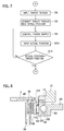
FIG. 4 , the vehicle is comprised of amain ECU 225 and a transmission device ECU 227. For the convenience of explanation, themain ECU 225 will be treated as a single unit hereinafter but may be a group of plural ECUs, each of which can independently control the engine, the transmission, the motor/generator, breaks or such. Further the ECUs may exchange information with the other by means of so-called CAN communication. - The
main ECU 225 or thetransmission ECU 227 is connected to a plurality of sensors to receive signals therefrom. The sensors detect, for example, rotation speed of theengine 201, rotation speed of the motor/generator 203, rotation speed of each wheel, an accelerator position, acceleration rates in the traveling direction and the lateral direction, a yaw rate, temperature in thetransmission device 1, torque of an output shaft, a break position, a side-break position, a shift position in the gearbox, a rudder angle of the steering, oil temperatures at respective parts, and an ambient temperature, thereby collecting information about various parts in the vehicle. The respective ECUs in turn select collected information, execute calculation, and compare results with recorded charts to output control information to the respective parts in the vehicle and control respective devices. - The transmission device ECU 227 receives the output from the temperature sensor and estimates the temperature in the
transmission device 1. Thetransmission device 1 is further comprised of a torque sensor consisting of a resolver detecting torque transmitted to therear differential 219 and the transmission device ECU 227 is further connected to this torque sensor to receive its signals. The transmission device ECU 227 is connected to respective elements in thetransmission device 1, such as a motor (actuator) 9, areduction mechanism 11, and acam mechanism 13 for example, to collect information therefrom, and further controls them to control operation of theclutch 7. - The
main ECU 225 and thetransmission device ECU 227, in accordance with the flowchart shown inFIG. 5 , detect respective status of respective parts through the sensors (S1), and input detected signals to the transmission device ECU 227 (S2). The transmission device ECU 227 determines target torque that therear differential 219 is made to transmit and controls power supply to themotor 9 according to the determined target torque (S3). - The transmission device ECU 227 subsequently, in accordance with the flowchart shown in
FIG. 6 , determines whether the torque input from the torque sensor matches up with the target torque (S7), and then set the control back to S4 if they match up, or modify power supply to themotor 9 until they match up if they not so as to control operation of the clutch 7 (S5). - Alternatively, the
main ECU 225 and thetransmission ECU 227 may, in accordance with the flowchart shown inFIG. 7 , execute control based on a target position instead of the target torque. As the target position, the rotational angle of themotor 9 may be selected. More specifically, a target torque is input to the ECU 227 (S4), a target position is calculated from the target torque (S8), an actual position (rotational angle) of themotor 9 is detected (S10), and operation of theclutch 7 is controlled by modifying power supply to themotor 9 until the actual position matches up with the target position (S11). - Under the control as described above executed by the
main ECU 225 and thetransmission device ECU 227, thetransmission device 1 of the present embodiment can control torque distribution to the front and rear axles. This control allows selection of drive modes depending on conditions of roads and conditions of vehicle's motion and control of torque distribution, thereby realizing stable and improvement in fuel consumption. - Referring mainly to
FIG. 1 , details of thetransmission device 1 will be described. Thetransmission device 1 interruptibly transmits torque between a first rotary member (such as the propeller shaft 217) and a second rotary member (such as a gear for transmitting torque to the rear differential 219), both of which are rotatable about an axis C1. - The
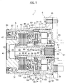
transmission device 1 is in general comprised of aclutch 7, amotor 9, areduction mechanism 11, and acam mechanism 13 and the whole of them is housed and used in acasing 6. Themotor 9 is a source for exerting pressure to theclutch 7. Rotation of themotor 9 is reduced in speed (in other words, its force is multiplied) by thereduction mechanism 11 and the resultant rotary motion is converted into an axial motion by thecam mechanism 13, so that the multiplied pressure force acts on theclutch 7. - The
clutch 7 is comprised of aclutch drum 3 to be combined with the first rotary member and aclutch hub 5 to be combined with the second rotary member, which are coaxial and both rotatable about the axis C1. - The
clutch hub 5, at least in part, gets in theclutch drum 3 and clutch plates elongated from both of them overlap with each other to form a multiplate clutch. A clutch of any other type, such as a cone clutch, may be used instead of the multiplate clutch. - In a case of the multiplate clutch, preferably formed on the internal periphery of the
clutch drum 3 aresplines 45, which mesh with the plurality of outerclutch plates 46. Further preferably formed on the external periphery of theclutch hub 5 aresplines 61, which mesh with the plurality of innerclutch plates 62. The outerclutch plates 46 and the innerclutch plates 62 are arranged alternately and, when the pressure force acts thereon in the axial direction, create frictional force, thereby transmitting torque therebetween. - The
clutch drum 3 is extended in the axial direction (leftward in the referred drawing) from the part where theclutch hub 5 overlaps therewith, and is exposed to the opening of thecasing 6, thereby serving for coupling with thepropeller shaft 217 or such. For coupling, the extended part is made thicker in its radial direction and has a plurality of tapped holes 47. - The
clutch drum 3 is, preferably at this extended part, rotatably supported by abearing 31 supported on an inner periphery of thecasing 6. Theclutch drum 3 is further supported at a proper position axially apart from the bearing 31 by another bearing 33 in a rotatable manner. Thebearing 33 may be supported by an inner periphery of thecasing 6 but is preferably supported by thereduction mechanism 11, in particular its fixedmember 21. This structure is advantageous not only in space saving but also in facility for axis alignment between the clutch 7 and thereduction mechanism 11. Between thebearing 33 and theclutch drum 3 or thereduction mechanism 11, meanwhile, anadapter 4 may be interposed. - The
clutch hub 5 is extended in a direction opposite to theclutch drum 3 to form a shaft and an end thereof is exposed to an opening of thecasing 6. This opening is opposite to the opening where theclutch drum 3 is exposed. This end is served for coupling with the rear differential 219 or such and has a structure for coupling, such assplines 59, on its internal periphery for example. Theclutch hub 5 is preferably in a hollow cylindrical shape, which contributes to weight reduction. - The
clutch hub 5 is, preferably around its end, rotatably supported by abearing 49 supported on the inner periphery of theclutch drum 3 and, around its opposite end, supported by thereduction mechanism 11, in particular by theinput member 17 thereof. Interposed therein is aneedle bearing 51 for example. This structure is also advantageous not only in space saving but also in facility for axis alignment between the clutch 7 and thereduction mechanism 11. Particularly if theclutch drum 3 and theclutch hub 5 are both supported by thereduction mechanism 11, this makes it very easy to axially align these three components. - The
motor 9 is comprised of astator 63, arotor 65 rotating relative to thestator 63, and acoil 69 electromagnetically driving therotor 65. Wiring of thecoil 69 is led out via aconnector 79 and is then connected to the power source. Further this wiring is also connected to thetransmission device ECU 227 and is subject to its control so that rotation of therotor 65 is controlled. - The whole of the
motor 9 is housed in amotor housing 67 and acover body 73 covering it, and thestator 63 is fixedly supported thereby. This is so structured that any of them are coaxial around the axis C1 but may be modified into a structure where at least therotor 65 is coaxial around and rotatable about the axis C1. Themotor housing 67 is pressed into thecasing 6 and thus the whole of themotor 9 is fixed to thecasing 6. - The
reduction mechanism 11 is in general comprised of aninput member 17 rotatable about the axis C1, a fixedmember 21 immovable about the axis C1, anintermediate member 25 rotatably fitting in the fixedmember 21, and anoutput member 29 engaging with theintermediate member 25. Theinput member 17 is coupled with therotor 65 to receive its rotation and theoutput member 29 outputs rotation reduced in speed to thecam mechanism 13. - Details of the respective elements in the
reduction mechanism 11 will be described hereinafter with reference toFIG. 2 in combination withFIG. 1 . - The
input member 17 has a structure similar to a cylinder, and is combined with therotor 65 and rotatable about the axis C1. To set this in a rotatable condition, preferably a bearing 81 and abearing 83 support theinput member 17. Thebearing 83 may be supported by themotor housing 67 and the bearing 81 may be supported by thecover body 73. - The
input member 17 is, around the part combined with therotor 65, a cylinder that is rotationally symmetrical about the axis C1, and is extended therefrom toward theclutch 7. This extended part is aneccentric shaft 15 that is eccentric relative to the axis C1. While C2 inFIGs. 1 and2 depicts a central axis of theeccentric shaft 15, the axis C2 deviates from the axis C1 at a deviation δc. When theinput member 17 rotates about the axis C1, theeccentric shaft 15 and the axis C2 make eccentric motions about the axis C1. - The fixed
member 21 has a pan-like structure that is rotationally symmetrical about the axis C1, and is preferably fixed to themotor 9 and immovable about the axis C1. For fixation, one or more bolts 71 penetrating themotor housing 67 and tightened into the fixedmember 21 may be used. This structure enables a production process of producing themotor 9 in advance, subsequently combining thereduction mechanism 11 with themotor 9 by means of the bolts 71, and next combining the whole of them with theclutch 7. - The fixed
member 21, on its internal periphery, has a structure for meshing with theintermediate member 25, an example of which is an internallytoothed gear 19. - The
intermediate member 25 has a structure similar to a disk and at its center fits around theeccentric shaft 15 to make an eccentric motion together. In between theintermediate member 25 and theeccentric shaft 15 interposed is abearing 85 for example, thereby being rotatable relative to each other. - The
intermediate member 25, at its external periphery, has a structure for meshing with the fixedmember 21, an example of which is an externallytoothed gear 23. As theintermediate member 25 meshes with the fixedmember 21 and also makes an eccentric motion along with theeccentric shaft 15, it could create a rotary motion about the axis C2. As the rotary motion would not be created if the teeth number of the internallytoothed gear 19 was the same as the teeth number of the externallytoothed gear 23, they are different numbers. Preferably the teeth number of the internallytoothed gear 19 can be greater by one or more than the teeth number of the externallytoothed gear 23. - To the tooth shape of the internally
toothed gear 19 and the externallytoothed gear 23 applicable is any of an involute tooth form, a cycloid tooth form, a circular arc tooth form, or epitrochoid tooth form. - The
output member 29 also has a structure similar to a cylinder and is, on its outer periphery for example, rotatably supported by the fixedmember 21. This support may be either by mutual sliding contact or by interposing a bearing. Thisoutput member 29 at one end thereof engages with theintermediate member 25. - For engagement, the
intermediate member 25 and theoutput member 29 have an engagingportion 27. The engagingportion 27 consists of a plurality of engagingholes 87 opened on theintermediate member 25 along a circle around the axis C2, and a plurality of engagingpins 89 projecting from theoutput member 29 corresponding thereto. The engagingholes 87 may be bottomed holes or through-holes. In order to absorb a difference between respective rotation centers thereof, the respective engagingholes 87 are formed larger than the respective engaging pins 89. In order to reduce friction between the engagingholes 87 and the engagingpins 89, sliding bushes or bearings may be interposed therebetween. On the basis of such engagement, theoutput member 29 follows theintermediate member 25 to rotate about the axis C1. - The
output member 29, at the end opposite to the engagingpins 89 and on its outer periphery, may be comprised of a structure, such assplines 91 for example, for engaging with acam follower 93 described later. - The
cam mechanism 13 intervenes between theoutput member 29 and theclutch 7. Thecam mechanism 13 in general consists of acam disk 90 and thecam follower 93, and may have an intervening member such as acam ball 95 interposed therebetween. Thecam follower 93 is comprised of apressure face 97 for pressing the clutch 7. Thecam mechanism 13 converts the rotary motion of theoutput member 29 into a motion in the axial direction, so that thepressure face 97 presses theclutch 7. - Referring to
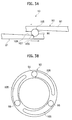
FIG. 3A and FIG. 3C , thecam disk 90 and thecam follower 93 are circular members opposed to each other. One or both of them have a plurality of cam faces 105 sloping toward these circumferential directions so as to get shallower. When thecam disk 90 rotates, theirrotational cam follower 93 is pressed out along the sloping faces of the cam faces 105, thereby converting the rotary motion into the axial motion. In order to make the force acting on thecam mechanism 13 be axially symmetrical, the cam faces 105 preferably exhibit rotational symmetry about the axis C1. - Each
cam face 105 may consist of afirst slope 107 that is relatively steep and asecond slope 109 that is rather gradual. Such a structure makes a ratio (stroke ratio) of a distance by the axial motion to a distance by the rotary motion be a profile such as one described below. - In an initial state, the
cam ball 95 rests on a bottom of thefirst slope 107. When theoutput member 29 transmits its rotation to thecam mechanism 13, thecam ball 95 initially goes up the steepfirst slope 107 and therefore thecam follower 93 makes an axial motion with a relatively large stroke ratio. This construction creates relatively small pressure force but rapidly shifts thepressure face 97 toward theclutch 7. As great pressure force is unnecessary until thepressure face 97 butts against theclutch 7, this is preferable in this stage. Thecam ball 95 next goes up the gradualsecond slope 109 and therefore thecam follower 93 makes an axial motion with a relatively small stroke ratio. This construction creates relatively large pressure force and is preferable in the stage where relatively large pressure force is required just after thepressure face 97 butts against theclutch 7. - Referring again to
FIG. 1 , thecam disk 90 is fixed to, or forms a unitary body with, the fixedmember 21. Thecam follower 93 engages with, and rotates along with, theoutput member 29, but is slidable in the axial direction. As described already, when thecam follower 93 is made to rotate by theoutput member 29, the rotation makes thecam follower 93 shift in the axial direction, and the pressure face 94 therefore presses theclutch 7. Apressure body 99 may intervene between thepressure face 97 and theclutch 7, and further athrust bearing 101 may intervene therebetween for the purpose of allowing relative rotation. To return thecam follower 93 to the initial position, areturn spring 103 may intervene between the clutch 7 and thepressure face 97 or thepressure body 99. - As being alternative to the aforementioned structure, the
cam disk 90 may be fixed to, or unitary with, theoutput member 29 as shown inFIG. 8 . Thecam follower 93 may correspondingly engage with the fixedmember 21, thereby being movable in the direction along the axis C1 but immovable around the axis C1. When thecam disk 90 is forced to rotate by theoutput member 29, the rotation makes thecam follower 93 shift in the axial direction, and thepressure face 97 therefore presses theclutch 7. - The
casing 6 has a structure similar to a cylinder and its both ends are, as described already, opened in the axial direction. The first opening allows access to theclutch drum 3 and the second opening allows access to theclutch hub 5. Thecasing 6, when fixed by means ofbolts 8, constitutes a part of acasing 35 belonging to the vehicle body and gets immovable around the axis C1. As themotor 9 is relatively heavy among constituent elements and is close to the second opening fixed by thebolts 8, this structure enables stiff support, thereby it is advantageous in prevention of vibration. - The
transmission device 1 further has some structures for shielding the interior of thecasing 6 from the exterior. For example, theclutch drum 3 may have a wall for blocking its interior. For the convenience of injecting lubrication oil therein, this wall may have a through-hole 41. After injection, preferably acheck ball 43 is pressed into and thus closes the through-hole 41. Theclutch hub 5 may similarly have apartitioning wall 53 for blocking the interior. - Between the
clutch drum 3 and thecasing 6, aseal member 37 may be interposed so as to abut on both of them, thereby closing a gap therebetween. Preferably adust cover 39 covers theseal member 37. Between theclutch hub 5 and themotor housing 67, aseal member 57 may be interposed so as to abut on both of them. Further between themotor housing 67 and thecasing 6, aseal member 75 such as an O-ring may be interposed. Still further, between themotor housing 67 and thecover body 73, aseal member 77 such as an O-ring may be interposed. - In accordance with the structure as described above, any foreign matter from the exterior does not intrude into the
transmission device 1. Further the lubrication oil in the interior does not leak out and is prevented from mixing with any lubrication oil at the exterior. Thetransmission device 1 can be handled independently from the exterior structure. - Further, the
transmission device 1 has a structure for promoting circulation of the lubrication oil within thecasing 6. Theclutch hub 5 may be comprised of a plurality of lubrication holes 55 penetrating itself in radial directions. Theclutch hub 5 is, as being coupled with therear differential 219, driven by therear wheels 223 to steadily rotate as long as the vehicle is running. Centrifugal force by the rotation forces the lubrication oil out through the lubrication holes 55 and then the respective parts of thetransmission device 1 are lubricated. - While the description above has been given to the example where the
clutch drum 3 is coupled with thepropeller shaft 217 and theclutch hub 5 is coupled withrear differential 219, a converse relation may be possible. Alternatively, thetransmission device 1 may be usable for interrupting power transmission between the other shafts. - According to the present embodiment, as the
intermediate member 25 meshes with the fixedmember 21 and as well makes an eccentric motion along with theeccentric shaft 15 to use the created rotary motion for reducing the rotation speed, a very great reduction ratio can be realized. In a case where the engagement between theintermediate member 25 and the fixedmember 21 is established by the internallytoothed gear 19 and the externallytoothed gear 23, which have distinct teeth numbers, the reduction ratio is determined by these teeth numbers and the difference therebetween. For example, in a case where the teeth number of the internallytoothed gear 19 is 50 and the teeth number of the externallytoothed gear 23 is 49, while themotor 9 rotates one revolution, theoutput member 29 merely rotates one-fifteenth revolution. As the reduction ratio is far greater than the prior art, the output of themotor 9 is multiplied to the far greater extent and then converted into the pressure force in the axial direction by means of thecam mechanism 13. Thetransmission device 1 of the present embodiment can therefore connect the clutch 7 with relatively great force even with a low-capacity motor 9. Further, the embodiment can, as using the gradually sloping cam face to create the pressure force, gradually increase or decrease the pressure force. More specifically, the present embodiment has an excellent controllability and therefore readily realizes the operation to control torque distribution to the rear wheels. - Further, in accordance with the present embodiment, a complex gear mechanism is unnecessary to obtain a great reduction ratio. Therefore it allows size reduction of the structure particularly in its axial direction. It is unnecessary to use a wide space in the vehicle for installing the
transmission device 1 therein. Further, as the weight gain is relatively small, it is advantageous in reducing fuel consumption. - Moreover, as the interior of the
casing 6 is shielded from the exterior, thetransmission device 1 of the present embodiment provides easy handleability. - While the description above has been given to the example where the
transmission device 1 is at the stage subsequent to thepropeller shaft 217, of course thepower takeoff 213 may be interposed between a shaft led out of the transmission and thepropeller shaft 217 so as to control torque transmission therebetween. Alternatively it may be interposed between any wheel and an axle so as to control torque transmission therebetween. Further, it may be used in an on-demand transfer at a part where a main drive path and a sub drive path branch off, so as to control torque transmission therebetween. - Further, to obtain higher reduction ratio, two stages of
reduction mechanisms 11 may be connected in series. - Although the invention has been described above by reference to certain exemplary embodiments of the invention, the invention is not limited to the exemplary embodiments described above. Modifications and variations of the embodiments described above will occur to those skilled in the art, in light of the above teachings.
- Provided is a transmission device of a small size and having an excellent controllability of pressure force to a clutch.
Claims (7)
- A transmission device for interruptibly transmitting torque between a first rotary member and a second rotary member respectively rotatable about an axis, the transmission device comprising:a clutch disconnectably and drivingly coupling the first rotary member with the second rotary member;a motor including a rotor rotatable about the axis;an input member coupled with the rotor and rotatable about the axis, the input member including an eccentric shaft eccentric relative to the axis;a fixed member immovable about the axis;an intermediate member fitting with the eccentric shaft to make an eccentric motion and meshing with the fixed member to make a rotary motion about the eccentric shaft;an output member rotatable about the axis and fitting with and following the intermediate member; anda cam mechanism intervening between the output member and the clutch to convert a rotary motion of the output member into a motion in a direction along the axis to press the clutch.
- The transmission device of claim 1, wherein the fixed member comprises an internally toothed gear having a first teeth number and the intermediate member comprises an externally toothed gear meshing with the internally toothed gear and having a second teeth number smaller in number than the first teeth number, whereby the intermediate member meshes with the fixed member.
- The transmission device of claim 1, wherein the cam mechanism includes:a cam disk coupled with or forming a unitary body with one selected from the group consisting of the fixed member and the output member; anda cam follower engaging in a way to be movable in the direction along the axis with another selected from the group consisting of the fixed member and the output member and driven by the cam disk to make a motion in the direction along the axis to press the clutch.
- The transmission device of claim 1, wherein the clutch includes a clutch drum combinable with the first rotary member and a clutch hub combinable with the second rotary member and disposed at least partly inside the clutch drum.
- The transmission device of claim 4, wherein the clutch drum and the input member rotatably support the clutch hub.
- The transmission device of claim 4, wherein the fixed member rotatably supports the clutch drum.
- The transmission device of claim 4, further comprising:a casing at least housing the clutch and the motor, and having a first opening opened in the direction along the axis to allow access to the clutch drum and a second opening opened in the direction along the axis to allow access to the clutch hub,wherein the motor is so disposed as to be exposed to the second opening.
Applications Claiming Priority (2)
| Application Number | Priority Date | Filing Date | Title |
|---|---|---|---|
| JP2013232087 | 2013-11-08 | ||
| PCT/JP2014/079649 WO2015068822A1 (en) | 2013-11-08 | 2014-11-07 | Power transmission device |
Publications (3)
| Publication Number | Publication Date |
|---|---|
| EP3067583A1 true EP3067583A1 (en) | 2016-09-14 |
| EP3067583A4 EP3067583A4 (en) | 2017-06-14 |
| EP3067583B1 EP3067583B1 (en) | 2019-03-13 |
Family
ID=53041596
Family Applications (1)
| Application Number | Title | Priority Date | Filing Date |
|---|---|---|---|
| EP14860626.2A Active EP3067583B1 (en) | 2013-11-08 | 2014-11-07 | Power transmission device |
Country Status (5)
| Country | Link |
|---|---|
| US (1) | US9534663B2 (en) |
| EP (1) | EP3067583B1 (en) |
| JP (1) | JP6200515B2 (en) |
| CN (1) | CN105705816B (en) |
| WO (2) | WO2015068822A1 (en) |
Cited By (4)
| Publication number | Priority date | Publication date | Assignee | Title |
|---|---|---|---|---|
| EP3181430A3 (en) * | 2015-12-16 | 2017-07-19 | Nabtesco Corporation | Steering assistance device |
| RU185563U1 (en) * | 2018-08-07 | 2018-12-11 | Общество с ограниченной ответственностью "Научно-инженерная компания "Объектные системы автоматики" (ООО "НИК "ОСА") | ELECTROMECHANICAL DRIVE |
| RU187959U1 (en) * | 2018-08-07 | 2019-03-26 | Общество с ограниченной ответственностью "Научно-инженерная компания "Объектные системы автоматики" (ООО "НИК "ОСА") | ELECTROMECHANICAL DRIVE |
| FR3073913A1 (en) * | 2017-11-22 | 2019-05-24 | Valeo Embrayages | TRANSMISSION DEVICE FOR A HYBRID VEHICLE |
Families Citing this family (26)
| Publication number | Priority date | Publication date | Assignee | Title |
|---|---|---|---|---|
| WO2016172285A1 (en) * | 2015-04-24 | 2016-10-27 | Sri International | Drives with partial cycloid teeth profile |
| JP6596995B2 (en) * | 2015-07-06 | 2019-10-30 | 株式会社ジェイテクト | Planetary roller type power transmission device |
| WO2017081749A1 (en) * | 2015-11-10 | 2017-05-18 | Gkn ドライブライン ジャパン株式会社 | Disconnectable power transfer unit |
| JP6735180B2 (en) * | 2016-03-04 | 2020-08-05 | ジーケーエヌ オートモーティブ リミテッド | A cam mechanism and a clutch device using this cam mechanism. |
| US10280987B2 (en) * | 2017-04-24 | 2019-05-07 | Schaeffler Technologies AG & Co. KG | Axial movement compensation of clutch actuation device |
| JP6502443B2 (en) * | 2017-09-01 | 2019-04-17 | 株式会社エフ・シー・シー | Power transmission |
| WO2019108868A1 (en) * | 2017-11-30 | 2019-06-06 | Parker-Hannifin Corporation | Vibration attenuation of mating gears in a power take-off |
| WO2020009202A1 (en) * | 2018-07-06 | 2020-01-09 | 株式会社デンソー | Clutch device |
| WO2020009187A1 (en) | 2018-07-06 | 2020-01-09 | 株式会社デンソー | Clutch device |
| JP7205394B2 (en) * | 2018-07-06 | 2023-01-17 | 株式会社デンソー | clutch device |
| JP2020159436A (en) * | 2019-03-26 | 2020-10-01 | 株式会社ジェイテクト | Driving power transmission device |
| CN109968969B (en) * | 2019-04-15 | 2020-10-16 | 常熟理工学院 | Electromagnetic control's light truck drive wheel antiskid |
| WO2021020316A1 (en) * | 2019-07-26 | 2021-02-04 | 株式会社デンソー | Clutch device |
| WO2021020318A1 (en) * | 2019-07-26 | 2021-02-04 | 株式会社デンソー | Clutch device |
| WO2021020317A1 (en) | 2019-07-26 | 2021-02-04 | 株式会社デンソー | Clutch device |
| CN114144593B (en) | 2019-07-26 | 2024-03-22 | 株式会社电装 | Clutch device |
| JP7272216B2 (en) | 2019-07-26 | 2023-05-12 | 株式会社デンソー | clutch device |
| DE112020003582T5 (en) | 2019-07-26 | 2022-04-21 | Denso Corporation | coupling device |
| DE112020003583T5 (en) | 2019-07-26 | 2022-04-21 | Denso Corporation | coupling device |
| CN114144599A (en) | 2019-07-26 | 2022-03-04 | 株式会社电装 | Clutch device |
| WO2021020313A1 (en) * | 2019-07-26 | 2021-02-04 | 株式会社デンソー | Clutch device |
| KR102285396B1 (en) * | 2020-02-10 | 2021-08-03 | 두산중공업 주식회사 | Apparatus for conveying driving force and Equipment for generating power comprising the same |
| KR102305974B1 (en) * | 2020-02-13 | 2021-09-28 | 두산중공업 주식회사 | Apparatus for conveying driving force and Equipment for generating power comprising the same |
| WO2022118846A1 (en) | 2020-12-03 | 2022-06-09 | 株式会社デンソー | Clutch device |
| DE112021006242T5 (en) | 2020-12-03 | 2023-10-05 | Denso Corporation | Clutch actuator |
| KR102553920B1 (en) * | 2021-09-24 | 2023-07-07 | 현대트랜시스 주식회사 | Controller for vehicle disconnector appratus and control method of vehicle disconnector apparatus based on temperature |
Citations (1)
| Publication number | Priority date | Publication date | Assignee | Title |
|---|---|---|---|---|
| JP2004316893A (en) * | 2003-03-31 | 2004-11-11 | Tochigi Fuji Ind Co Ltd | Torque transmitting coupling |
Family Cites Families (11)
| Publication number | Priority date | Publication date | Assignee | Title |
|---|---|---|---|---|
| US3561292A (en) * | 1969-02-11 | 1971-02-09 | Lorence Mfg Corp | Drive mechanism |
| JPH0539235Y2 (en) * | 1986-02-18 | 1993-10-05 | ||
| JPH04106543U (en) * | 1991-02-26 | 1992-09-14 | アイセル株式会社 | Eccentric swing type reducer |
| JP3952457B2 (en) * | 2002-10-07 | 2007-08-01 | 本田技研工業株式会社 | Actuator for power transmission device |
| DE102004015304A1 (en) * | 2003-03-31 | 2004-10-21 | Tochigi Fuji Sangyo K.K. | Torque transfer clutch |
| US7357748B2 (en) * | 2004-07-13 | 2008-04-15 | Borgwarner Inc. | Limited slip differential |
| US7896146B2 (en) * | 2006-12-20 | 2011-03-01 | Borgwarner, Inc. | Clutch device utilizing brushless motor |
| JP2009019743A (en) * | 2007-07-13 | 2009-01-29 | Gkn ドライブライン トルクテクノロジー株式会社 | Power transmission device |
| DE102010019699B4 (en) * | 2009-05-26 | 2021-07-29 | Magna powertrain gmbh & co kg | Multi-disc clutch |
| JP5855843B2 (en) * | 2011-04-20 | 2016-02-09 | Gknドライブラインジャパン株式会社 | Drive device |
| JP5998571B2 (en) * | 2012-03-28 | 2016-09-28 | 株式会社ジェイテクト | Driving force transmission device and four-wheel drive vehicle equipped with the same |
-
2014
- 2014-11-07 EP EP14860626.2A patent/EP3067583B1/en active Active
- 2014-11-07 WO PCT/JP2014/079649 patent/WO2015068822A1/en active Application Filing
- 2014-11-07 WO PCT/JP2014/079648 patent/WO2015068821A1/en active Application Filing
- 2014-11-07 JP JP2015546706A patent/JP6200515B2/en not_active Expired - Fee Related
- 2014-11-07 CN CN201480060941.2A patent/CN105705816B/en active Active
-
2016
- 2016-04-28 US US15/140,814 patent/US9534663B2/en active Active
Patent Citations (1)
| Publication number | Priority date | Publication date | Assignee | Title |
|---|---|---|---|---|
| JP2004316893A (en) * | 2003-03-31 | 2004-11-11 | Tochigi Fuji Ind Co Ltd | Torque transmitting coupling |
Non-Patent Citations (1)
| Title |
|---|
| See also references of WO2015068822A1 * |
Cited By (4)
| Publication number | Priority date | Publication date | Assignee | Title |
|---|---|---|---|---|
| EP3181430A3 (en) * | 2015-12-16 | 2017-07-19 | Nabtesco Corporation | Steering assistance device |
| FR3073913A1 (en) * | 2017-11-22 | 2019-05-24 | Valeo Embrayages | TRANSMISSION DEVICE FOR A HYBRID VEHICLE |
| RU185563U1 (en) * | 2018-08-07 | 2018-12-11 | Общество с ограниченной ответственностью "Научно-инженерная компания "Объектные системы автоматики" (ООО "НИК "ОСА") | ELECTROMECHANICAL DRIVE |
| RU187959U1 (en) * | 2018-08-07 | 2019-03-26 | Общество с ограниченной ответственностью "Научно-инженерная компания "Объектные системы автоматики" (ООО "НИК "ОСА") | ELECTROMECHANICAL DRIVE |
Also Published As
| Publication number | Publication date |
|---|---|
| JPWO2015068822A1 (en) | 2017-03-09 |
| EP3067583A4 (en) | 2017-06-14 |
| JP6200515B2 (en) | 2017-09-20 |
| US20160238107A1 (en) | 2016-08-18 |
| CN105705816B (en) | 2018-03-20 |
| US9534663B2 (en) | 2017-01-03 |
| CN105705816A (en) | 2016-06-22 |
| WO2015068821A1 (en) | 2015-05-14 |
| WO2015068822A1 (en) | 2015-05-14 |
| EP3067583B1 (en) | 2019-03-13 |
Similar Documents
| Publication | Publication Date | Title |
|---|---|---|
| US9534663B2 (en) | Transmission device | |
| CN108973630B (en) | Electric vehicle drive using a combined differential and reduction gear | |
| CN109153321B (en) | Electric drive device | |
| KR101718456B1 (en) | Hybrid driveline, vehicle with such a hybrid driveline, method to control such a hybrid driveline, computer program to control such a hybrid driveline and a computer program product comprising program code | |
| RU2502001C2 (en) | Drive and vehicle equipped therewith | |
| CN100441896C (en) | Electrohydraulic clutch assembly | |
| CN104589993A (en) | Drive unit for vehicles | |
| US9657826B1 (en) | Electric motor with coaxial clutch packs that provide differential and torque vectoring | |
| US20160207396A1 (en) | E-assist with torque vectoring | |
| WO2018144525A1 (en) | Multi-speed electric transaxle unit with co-axial shafts | |
| RU2532211C2 (en) | Drive mechanism for selective change-over of drive between traction mode and torque vectorisation mode | |
| EP2857243B1 (en) | Transaxle device | |
| KR101655578B1 (en) | Hybrid powertrain | |
| KR20140126710A (en) | Drive train of a purely electrically drivable motor vehicle | |
| EP2546086A2 (en) | Transfer case with planetary gear range shifting | |
| US9534665B1 (en) | Electrical all-wheel drive | |
| US10479199B2 (en) | Disconnectable power transfer unit | |
| CN216139798U (en) | Electric drive axle | |
| JP2002160540A (en) | Drive unit for hybrid vehicle | |
| KR101408465B1 (en) | Two-speed transmission for electric vehicle | |
| CN109804183B (en) | Transmission for a motor vehicle | |
| CN103847515A (en) | Transfer | |
| CN201046665Y (en) | Hybrid power automobile transfer gear | |
| JP5975750B2 (en) | Power transmission device | |
| JP6794313B2 (en) | Power transmission device with parking brake |
Legal Events
| Date | Code | Title | Description |
|---|---|---|---|
| PUAI | Public reference made under article 153(3) epc to a published international application that has entered the european phase |
Free format text: ORIGINAL CODE: 0009012 |
|
| 17P | Request for examination filed |
Effective date: 20160426 |
|
| AK | Designated contracting states |
Kind code of ref document: A1 Designated state(s): AL AT BE BG CH CY CZ DE DK EE ES FI FR GB GR HR HU IE IS IT LI LT LU LV MC MK MT NL NO PL PT RO RS SE SI SK SM TR |
|
| AX | Request for extension of the european patent |
Extension state: BA ME |
|
| DAX | Request for extension of the european patent (deleted) | ||
| A4 | Supplementary search report drawn up and despatched |
Effective date: 20170515 |
|
| RIC1 | Information provided on ipc code assigned before grant |
Ipc: F16H 1/32 20060101ALI20170509BHEP Ipc: F16D 28/00 20060101AFI20170509BHEP |
|
| GRAP | Despatch of communication of intention to grant a patent |
Free format text: ORIGINAL CODE: EPIDOSNIGR1 |
|
| STAA | Information on the status of an ep patent application or granted ep patent |
Free format text: STATUS: GRANT OF PATENT IS INTENDED |
|
| INTG | Intention to grant announced |
Effective date: 20181019 |
|
| GRAS | Grant fee paid |
Free format text: ORIGINAL CODE: EPIDOSNIGR3 |
|
| GRAA | (expected) grant |
Free format text: ORIGINAL CODE: 0009210 |
|
| STAA | Information on the status of an ep patent application or granted ep patent |
Free format text: STATUS: THE PATENT HAS BEEN GRANTED |
|
| RAP1 | Party data changed (applicant data changed or rights of an application transferred) |
Owner name: GKN DRIVELINE JAPAN LTD |
|
| AK | Designated contracting states |
Kind code of ref document: B1 Designated state(s): AL AT BE BG CH CY CZ DE DK EE ES FI FR GB GR HR HU IE IS IT LI LT LU LV MC MK MT NL NO PL PT RO RS SE SI SK SM TR |
|
| REG | Reference to a national code |
Ref country code: GB Ref legal event code: FG4D |
|
| REG | Reference to a national code |
Ref country code: CH Ref legal event code: EP Ref country code: AT Ref legal event code: REF Ref document number: 1108115 Country of ref document: AT Kind code of ref document: T Effective date: 20190315 |
|
| REG | Reference to a national code |
Ref country code: IE Ref legal event code: FG4D |
|
| REG | Reference to a national code |
Ref country code: DE Ref legal event code: R096 Ref document number: 602014043019 Country of ref document: DE |
|
| REG | Reference to a national code |
Ref country code: NL Ref legal event code: MP Effective date: 20190313 |
|
| REG | Reference to a national code |
Ref country code: LT Ref legal event code: MG4D |
|
| PG25 | Lapsed in a contracting state [announced via postgrant information from national office to epo] |
Ref country code: NO Free format text: LAPSE BECAUSE OF FAILURE TO SUBMIT A TRANSLATION OF THE DESCRIPTION OR TO PAY THE FEE WITHIN THE PRESCRIBED TIME-LIMIT Effective date: 20190613 Ref country code: LT Free format text: LAPSE BECAUSE OF FAILURE TO SUBMIT A TRANSLATION OF THE DESCRIPTION OR TO PAY THE FEE WITHIN THE PRESCRIBED TIME-LIMIT Effective date: 20190313 Ref country code: FI Free format text: LAPSE BECAUSE OF FAILURE TO SUBMIT A TRANSLATION OF THE DESCRIPTION OR TO PAY THE FEE WITHIN THE PRESCRIBED TIME-LIMIT Effective date: 20190313 Ref country code: SE Free format text: LAPSE BECAUSE OF FAILURE TO SUBMIT A TRANSLATION OF THE DESCRIPTION OR TO PAY THE FEE WITHIN THE PRESCRIBED TIME-LIMIT Effective date: 20190313 |
|
| PG25 | Lapsed in a contracting state [announced via postgrant information from national office to epo] |
Ref country code: BG Free format text: LAPSE BECAUSE OF FAILURE TO SUBMIT A TRANSLATION OF THE DESCRIPTION OR TO PAY THE FEE WITHIN THE PRESCRIBED TIME-LIMIT Effective date: 20190613 Ref country code: HR Free format text: LAPSE BECAUSE OF FAILURE TO SUBMIT A TRANSLATION OF THE DESCRIPTION OR TO PAY THE FEE WITHIN THE PRESCRIBED TIME-LIMIT Effective date: 20190313 Ref country code: LV Free format text: LAPSE BECAUSE OF FAILURE TO SUBMIT A TRANSLATION OF THE DESCRIPTION OR TO PAY THE FEE WITHIN THE PRESCRIBED TIME-LIMIT Effective date: 20190313 Ref country code: GR Free format text: LAPSE BECAUSE OF FAILURE TO SUBMIT A TRANSLATION OF THE DESCRIPTION OR TO PAY THE FEE WITHIN THE PRESCRIBED TIME-LIMIT Effective date: 20190614 Ref country code: RS Free format text: LAPSE BECAUSE OF FAILURE TO SUBMIT A TRANSLATION OF THE DESCRIPTION OR TO PAY THE FEE WITHIN THE PRESCRIBED TIME-LIMIT Effective date: 20190313 Ref country code: NL Free format text: LAPSE BECAUSE OF FAILURE TO SUBMIT A TRANSLATION OF THE DESCRIPTION OR TO PAY THE FEE WITHIN THE PRESCRIBED TIME-LIMIT Effective date: 20190313 |
|
| REG | Reference to a national code |
Ref country code: AT Ref legal event code: MK05 Ref document number: 1108115 Country of ref document: AT Kind code of ref document: T Effective date: 20190313 |
|
| PG25 | Lapsed in a contracting state [announced via postgrant information from national office to epo] |
Ref country code: IT Free format text: LAPSE BECAUSE OF FAILURE TO SUBMIT A TRANSLATION OF THE DESCRIPTION OR TO PAY THE FEE WITHIN THE PRESCRIBED TIME-LIMIT Effective date: 20190313 Ref country code: RO Free format text: LAPSE BECAUSE OF FAILURE TO SUBMIT A TRANSLATION OF THE DESCRIPTION OR TO PAY THE FEE WITHIN THE PRESCRIBED TIME-LIMIT Effective date: 20190313 Ref country code: SK Free format text: LAPSE BECAUSE OF FAILURE TO SUBMIT A TRANSLATION OF THE DESCRIPTION OR TO PAY THE FEE WITHIN THE PRESCRIBED TIME-LIMIT Effective date: 20190313 Ref country code: CZ Free format text: LAPSE BECAUSE OF FAILURE TO SUBMIT A TRANSLATION OF THE DESCRIPTION OR TO PAY THE FEE WITHIN THE PRESCRIBED TIME-LIMIT Effective date: 20190313 Ref country code: ES Free format text: LAPSE BECAUSE OF FAILURE TO SUBMIT A TRANSLATION OF THE DESCRIPTION OR TO PAY THE FEE WITHIN THE PRESCRIBED TIME-LIMIT Effective date: 20190313 Ref country code: PT Free format text: LAPSE BECAUSE OF FAILURE TO SUBMIT A TRANSLATION OF THE DESCRIPTION OR TO PAY THE FEE WITHIN THE PRESCRIBED TIME-LIMIT Effective date: 20190713 Ref country code: EE Free format text: LAPSE BECAUSE OF FAILURE TO SUBMIT A TRANSLATION OF THE DESCRIPTION OR TO PAY THE FEE WITHIN THE PRESCRIBED TIME-LIMIT Effective date: 20190313 Ref country code: AL Free format text: LAPSE BECAUSE OF FAILURE TO SUBMIT A TRANSLATION OF THE DESCRIPTION OR TO PAY THE FEE WITHIN THE PRESCRIBED TIME-LIMIT Effective date: 20190313 |
|
| PG25 | Lapsed in a contracting state [announced via postgrant information from national office to epo] |
Ref country code: SM Free format text: LAPSE BECAUSE OF FAILURE TO SUBMIT A TRANSLATION OF THE DESCRIPTION OR TO PAY THE FEE WITHIN THE PRESCRIBED TIME-LIMIT Effective date: 20190313 Ref country code: PL Free format text: LAPSE BECAUSE OF FAILURE TO SUBMIT A TRANSLATION OF THE DESCRIPTION OR TO PAY THE FEE WITHIN THE PRESCRIBED TIME-LIMIT Effective date: 20190313 |
|
| REG | Reference to a national code |
Ref country code: DE Ref legal event code: R097 Ref document number: 602014043019 Country of ref document: DE |
|
| PG25 | Lapsed in a contracting state [announced via postgrant information from national office to epo] |
Ref country code: IS Free format text: LAPSE BECAUSE OF FAILURE TO SUBMIT A TRANSLATION OF THE DESCRIPTION OR TO PAY THE FEE WITHIN THE PRESCRIBED TIME-LIMIT Effective date: 20190713 Ref country code: AT Free format text: LAPSE BECAUSE OF FAILURE TO SUBMIT A TRANSLATION OF THE DESCRIPTION OR TO PAY THE FEE WITHIN THE PRESCRIBED TIME-LIMIT Effective date: 20190313 |
|
| PLBE | No opposition filed within time limit |
Free format text: ORIGINAL CODE: 0009261 |
|
| STAA | Information on the status of an ep patent application or granted ep patent |
Free format text: STATUS: NO OPPOSITION FILED WITHIN TIME LIMIT |
|
| PG25 | Lapsed in a contracting state [announced via postgrant information from national office to epo] |
Ref country code: DK Free format text: LAPSE BECAUSE OF FAILURE TO SUBMIT A TRANSLATION OF THE DESCRIPTION OR TO PAY THE FEE WITHIN THE PRESCRIBED TIME-LIMIT Effective date: 20190313 |
|
| 26N | No opposition filed |
Effective date: 20191216 |
|
| PG25 | Lapsed in a contracting state [announced via postgrant information from national office to epo] |
Ref country code: SI Free format text: LAPSE BECAUSE OF FAILURE TO SUBMIT A TRANSLATION OF THE DESCRIPTION OR TO PAY THE FEE WITHIN THE PRESCRIBED TIME-LIMIT Effective date: 20190313 |
|
| PG25 | Lapsed in a contracting state [announced via postgrant information from national office to epo] |
Ref country code: TR Free format text: LAPSE BECAUSE OF FAILURE TO SUBMIT A TRANSLATION OF THE DESCRIPTION OR TO PAY THE FEE WITHIN THE PRESCRIBED TIME-LIMIT Effective date: 20190313 |
|
| REG | Reference to a national code |
Ref country code: CH Ref legal event code: PL |
|
| PG25 | Lapsed in a contracting state [announced via postgrant information from national office to epo] |
Ref country code: LU Free format text: LAPSE BECAUSE OF NON-PAYMENT OF DUE FEES Effective date: 20191107 Ref country code: MC Free format text: LAPSE BECAUSE OF FAILURE TO SUBMIT A TRANSLATION OF THE DESCRIPTION OR TO PAY THE FEE WITHIN THE PRESCRIBED TIME-LIMIT Effective date: 20190313 Ref country code: LI Free format text: LAPSE BECAUSE OF NON-PAYMENT OF DUE FEES Effective date: 20191130 Ref country code: CH Free format text: LAPSE BECAUSE OF NON-PAYMENT OF DUE FEES Effective date: 20191130 |
|
| REG | Reference to a national code |
Ref country code: BE Ref legal event code: MM Effective date: 20191130 |
|
| GBPC | Gb: european patent ceased through non-payment of renewal fee |
Effective date: 20191107 |
|
| PG25 | Lapsed in a contracting state [announced via postgrant information from national office to epo] |
Ref country code: GB Free format text: LAPSE BECAUSE OF NON-PAYMENT OF DUE FEES Effective date: 20191107 Ref country code: IE Free format text: LAPSE BECAUSE OF NON-PAYMENT OF DUE FEES Effective date: 20191107 |
|
| PG25 | Lapsed in a contracting state [announced via postgrant information from national office to epo] |
Ref country code: BE Free format text: LAPSE BECAUSE OF NON-PAYMENT OF DUE FEES Effective date: 20191130 |
|
| PG25 | Lapsed in a contracting state [announced via postgrant information from national office to epo] |
Ref country code: CY Free format text: LAPSE BECAUSE OF FAILURE TO SUBMIT A TRANSLATION OF THE DESCRIPTION OR TO PAY THE FEE WITHIN THE PRESCRIBED TIME-LIMIT Effective date: 20190313 |
|
| PG25 | Lapsed in a contracting state [announced via postgrant information from national office to epo] |
Ref country code: FR Free format text: LAPSE BECAUSE OF NON-PAYMENT OF DUE FEES Effective date: 20191202 Ref country code: MT Free format text: LAPSE BECAUSE OF FAILURE TO SUBMIT A TRANSLATION OF THE DESCRIPTION OR TO PAY THE FEE WITHIN THE PRESCRIBED TIME-LIMIT Effective date: 20190313 Ref country code: HU Free format text: LAPSE BECAUSE OF FAILURE TO SUBMIT A TRANSLATION OF THE DESCRIPTION OR TO PAY THE FEE WITHIN THE PRESCRIBED TIME-LIMIT; INVALID AB INITIO Effective date: 20141107 |
|
| PG25 | Lapsed in a contracting state [announced via postgrant information from national office to epo] |
Ref country code: MK Free format text: LAPSE BECAUSE OF FAILURE TO SUBMIT A TRANSLATION OF THE DESCRIPTION OR TO PAY THE FEE WITHIN THE PRESCRIBED TIME-LIMIT Effective date: 20190313 |
|
| PGFP | Annual fee paid to national office [announced via postgrant information from national office to epo] |
Ref country code: DE Payment date: 20231120 Year of fee payment: 10 |