EP3067545A1 - Fuel vapor treatment system - Google Patents
Fuel vapor treatment system Download PDFInfo
- Publication number
- EP3067545A1 EP3067545A1 EP16157762.2A EP16157762A EP3067545A1 EP 3067545 A1 EP3067545 A1 EP 3067545A1 EP 16157762 A EP16157762 A EP 16157762A EP 3067545 A1 EP3067545 A1 EP 3067545A1
- Authority
- EP
- European Patent Office
- Prior art keywords
- pressure
- canister
- passage
- isolation valve
- fuel
- Prior art date
- Legal status (The legal status is an assumption and is not a legal conclusion. Google has not performed a legal analysis and makes no representation as to the accuracy of the status listed.)
- Granted
Links
- 239000000446 fuel Substances 0.000 title claims abstract description 74
- 238000010926 purge Methods 0.000 claims abstract description 140
- 238000000034 method Methods 0.000 claims abstract description 124
- 238000002955 isolation Methods 0.000 claims abstract description 97
- 239000002828 fuel tank Substances 0.000 claims abstract description 77
- 230000007423 decrease Effects 0.000 claims abstract description 30
- 238000002485 combustion reaction Methods 0.000 claims description 22
- 238000004891 communication Methods 0.000 claims description 14
- 238000003745 diagnosis Methods 0.000 claims description 14
- 238000011946 reduction process Methods 0.000 description 6
- 230000003247 decreasing effect Effects 0.000 description 3
- 239000000203 mixture Substances 0.000 description 3
- 238000001179 sorption measurement Methods 0.000 description 3
- 230000000694 effects Effects 0.000 description 2
- 238000002347 injection Methods 0.000 description 2
- 239000007924 injection Substances 0.000 description 2
- 239000003463 adsorbent Substances 0.000 description 1
- 230000015572 biosynthetic process Effects 0.000 description 1
- 238000010586 diagram Methods 0.000 description 1
- 238000005259 measurement Methods 0.000 description 1
- 238000011144 upstream manufacturing Methods 0.000 description 1
Images

Classifications
-
- F—MECHANICAL ENGINEERING; LIGHTING; HEATING; WEAPONS; BLASTING
- F02—COMBUSTION ENGINES; HOT-GAS OR COMBUSTION-PRODUCT ENGINE PLANTS
- F02M—SUPPLYING COMBUSTION ENGINES IN GENERAL WITH COMBUSTIBLE MIXTURES OR CONSTITUENTS THEREOF
- F02M25/00—Engine-pertinent apparatus for adding non-fuel substances or small quantities of secondary fuel to combustion-air, main fuel or fuel-air mixture
- F02M25/08—Engine-pertinent apparatus for adding non-fuel substances or small quantities of secondary fuel to combustion-air, main fuel or fuel-air mixture adding fuel vapours drawn from engine fuel reservoir
- F02M25/0809—Judging failure of purge control system
- F02M25/0818—Judging failure of purge control system having means for pressurising the evaporative emission space
-
- F—MECHANICAL ENGINEERING; LIGHTING; HEATING; WEAPONS; BLASTING
- F02—COMBUSTION ENGINES; HOT-GAS OR COMBUSTION-PRODUCT ENGINE PLANTS
- F02M—SUPPLYING COMBUSTION ENGINES IN GENERAL WITH COMBUSTIBLE MIXTURES OR CONSTITUENTS THEREOF
- F02M25/00—Engine-pertinent apparatus for adding non-fuel substances or small quantities of secondary fuel to combustion-air, main fuel or fuel-air mixture
- F02M25/08—Engine-pertinent apparatus for adding non-fuel substances or small quantities of secondary fuel to combustion-air, main fuel or fuel-air mixture adding fuel vapours drawn from engine fuel reservoir
-
- F—MECHANICAL ENGINEERING; LIGHTING; HEATING; WEAPONS; BLASTING
- F02—COMBUSTION ENGINES; HOT-GAS OR COMBUSTION-PRODUCT ENGINE PLANTS
- F02M—SUPPLYING COMBUSTION ENGINES IN GENERAL WITH COMBUSTIBLE MIXTURES OR CONSTITUENTS THEREOF
- F02M25/00—Engine-pertinent apparatus for adding non-fuel substances or small quantities of secondary fuel to combustion-air, main fuel or fuel-air mixture
- F02M25/08—Engine-pertinent apparatus for adding non-fuel substances or small quantities of secondary fuel to combustion-air, main fuel or fuel-air mixture adding fuel vapours drawn from engine fuel reservoir
- F02M25/0809—Judging failure of purge control system
-
- B—PERFORMING OPERATIONS; TRANSPORTING
- B60—VEHICLES IN GENERAL
- B60K—ARRANGEMENT OR MOUNTING OF PROPULSION UNITS OR OF TRANSMISSIONS IN VEHICLES; ARRANGEMENT OR MOUNTING OF PLURAL DIVERSE PRIME-MOVERS IN VEHICLES; AUXILIARY DRIVES FOR VEHICLES; INSTRUMENTATION OR DASHBOARDS FOR VEHICLES; ARRANGEMENTS IN CONNECTION WITH COOLING, AIR INTAKE, GAS EXHAUST OR FUEL SUPPLY OF PROPULSION UNITS IN VEHICLES
- B60K15/00—Arrangement in connection with fuel supply of combustion engines or other fuel consuming energy converters, e.g. fuel cells; Mounting or construction of fuel tanks
- B60K15/03—Fuel tanks
- B60K15/035—Fuel tanks characterised by venting means
-
- B—PERFORMING OPERATIONS; TRANSPORTING
- B60—VEHICLES IN GENERAL
- B60K—ARRANGEMENT OR MOUNTING OF PROPULSION UNITS OR OF TRANSMISSIONS IN VEHICLES; ARRANGEMENT OR MOUNTING OF PLURAL DIVERSE PRIME-MOVERS IN VEHICLES; AUXILIARY DRIVES FOR VEHICLES; INSTRUMENTATION OR DASHBOARDS FOR VEHICLES; ARRANGEMENTS IN CONNECTION WITH COOLING, AIR INTAKE, GAS EXHAUST OR FUEL SUPPLY OF PROPULSION UNITS IN VEHICLES
- B60K15/00—Arrangement in connection with fuel supply of combustion engines or other fuel consuming energy converters, e.g. fuel cells; Mounting or construction of fuel tanks
- B60K15/03—Fuel tanks
- B60K15/035—Fuel tanks characterised by venting means
- B60K15/03504—Fuel tanks characterised by venting means adapted to avoid loss of fuel or fuel vapour, e.g. with vapour recovery systems
-
- B—PERFORMING OPERATIONS; TRANSPORTING
- B60—VEHICLES IN GENERAL
- B60K—ARRANGEMENT OR MOUNTING OF PROPULSION UNITS OR OF TRANSMISSIONS IN VEHICLES; ARRANGEMENT OR MOUNTING OF PLURAL DIVERSE PRIME-MOVERS IN VEHICLES; AUXILIARY DRIVES FOR VEHICLES; INSTRUMENTATION OR DASHBOARDS FOR VEHICLES; ARRANGEMENTS IN CONNECTION WITH COOLING, AIR INTAKE, GAS EXHAUST OR FUEL SUPPLY OF PROPULSION UNITS IN VEHICLES
- B60K15/00—Arrangement in connection with fuel supply of combustion engines or other fuel consuming energy converters, e.g. fuel cells; Mounting or construction of fuel tanks
- B60K15/03—Fuel tanks
- B60K15/035—Fuel tanks characterised by venting means
- B60K15/03519—Valve arrangements in the vent line
-
- F—MECHANICAL ENGINEERING; LIGHTING; HEATING; WEAPONS; BLASTING
- F02—COMBUSTION ENGINES; HOT-GAS OR COMBUSTION-PRODUCT ENGINE PLANTS
- F02D—CONTROLLING COMBUSTION ENGINES
- F02D41/00—Electrical control of supply of combustible mixture or its constituents
- F02D41/0025—Controlling engines characterised by use of non-liquid fuels, pluralities of fuels, or non-fuel substances added to the combustible mixtures
- F02D41/003—Adding fuel vapours, e.g. drawn from engine fuel reservoir
-
- F—MECHANICAL ENGINEERING; LIGHTING; HEATING; WEAPONS; BLASTING
- F02—COMBUSTION ENGINES; HOT-GAS OR COMBUSTION-PRODUCT ENGINE PLANTS
- F02D—CONTROLLING COMBUSTION ENGINES
- F02D41/00—Electrical control of supply of combustible mixture or its constituents
- F02D41/0025—Controlling engines characterised by use of non-liquid fuels, pluralities of fuels, or non-fuel substances added to the combustible mixtures
- F02D41/003—Adding fuel vapours, e.g. drawn from engine fuel reservoir
- F02D41/0032—Controlling the purging of the canister as a function of the engine operating conditions
- F02D41/004—Control of the valve or purge actuator, e.g. duty cycle, closed loop control of position
-
- F—MECHANICAL ENGINEERING; LIGHTING; HEATING; WEAPONS; BLASTING
- F02—COMBUSTION ENGINES; HOT-GAS OR COMBUSTION-PRODUCT ENGINE PLANTS
- F02D—CONTROLLING COMBUSTION ENGINES
- F02D41/00—Electrical control of supply of combustible mixture or its constituents
- F02D41/22—Safety or indicating devices for abnormal conditions
-
- F—MECHANICAL ENGINEERING; LIGHTING; HEATING; WEAPONS; BLASTING
- F02—COMBUSTION ENGINES; HOT-GAS OR COMBUSTION-PRODUCT ENGINE PLANTS
- F02M—SUPPLYING COMBUSTION ENGINES IN GENERAL WITH COMBUSTIBLE MIXTURES OR CONSTITUENTS THEREOF
- F02M25/00—Engine-pertinent apparatus for adding non-fuel substances or small quantities of secondary fuel to combustion-air, main fuel or fuel-air mixture
- F02M25/08—Engine-pertinent apparatus for adding non-fuel substances or small quantities of secondary fuel to combustion-air, main fuel or fuel-air mixture adding fuel vapours drawn from engine fuel reservoir
- F02M25/0836—Arrangement of valves controlling the admission of fuel vapour to an engine, e.g. valve being disposed between fuel tank or absorption canister and intake manifold
-
- F—MECHANICAL ENGINEERING; LIGHTING; HEATING; WEAPONS; BLASTING
- F02—COMBUSTION ENGINES; HOT-GAS OR COMBUSTION-PRODUCT ENGINE PLANTS
- F02M—SUPPLYING COMBUSTION ENGINES IN GENERAL WITH COMBUSTIBLE MIXTURES OR CONSTITUENTS THEREOF
- F02M25/00—Engine-pertinent apparatus for adding non-fuel substances or small quantities of secondary fuel to combustion-air, main fuel or fuel-air mixture
- F02M25/08—Engine-pertinent apparatus for adding non-fuel substances or small quantities of secondary fuel to combustion-air, main fuel or fuel-air mixture adding fuel vapours drawn from engine fuel reservoir
- F02M25/0854—Details of the absorption canister
-
- F—MECHANICAL ENGINEERING; LIGHTING; HEATING; WEAPONS; BLASTING
- F02—COMBUSTION ENGINES; HOT-GAS OR COMBUSTION-PRODUCT ENGINE PLANTS
- F02M—SUPPLYING COMBUSTION ENGINES IN GENERAL WITH COMBUSTIBLE MIXTURES OR CONSTITUENTS THEREOF
- F02M25/00—Engine-pertinent apparatus for adding non-fuel substances or small quantities of secondary fuel to combustion-air, main fuel or fuel-air mixture
- F02M25/08—Engine-pertinent apparatus for adding non-fuel substances or small quantities of secondary fuel to combustion-air, main fuel or fuel-air mixture adding fuel vapours drawn from engine fuel reservoir
- F02M25/089—Layout of the fuel vapour installation
Definitions
- the present disclosure relates to a fuel vapor treatment system installed in an internal combustion engine and to a method for controlling the vapor treatment system.
- An internal combustion engine of a vehicle includes a fuel vapor treatment system having a canister that adsorbs fuel vapor to limit emission of fuel vapor generated in the fuel tank into the atmosphere.
- Japanese Laid-Open Patent Publication No. 2010-242723 describes a fuel vapor treatment system that includes a canister, a vapor passage, which introduces fuel vapor generated in the fuel tank into the canister, and an isolation valve, which opens and closes the vapor passage.
- the fuel vapor treatment system also includes a purge passage, which introduces fuel vapor desorbed from the canister into the intake passage of the internal combustion engine, a purge valve, which is located in the purge passage and adjusts the flow rate of fuel vapor, and an outside air introduction passage, which is connected to the canister and introduces outside air into the canister.
- the fuel vapor treatment system opens the purge valve to desorb fuel vapor from the canister while the engine is running.
- the desorbed fuel vapor is introduced into the intake passage through the purge passage and burned in the combustion chamber.
- Such a process is referred to as a purging process and maintains the adsorption capacity of the canister.
- the fuel vapor treatment system of the '723 publication opens the isolation valve when fuel consumption or decrease in the fuel temperature generates negative pressure (pressure lower than the atmospheric pressure) in the fuel tank. This returns the fuel vapor adsorbed by the canister to the fuel tank. When the pressure in the fuel tank becomes the atmospheric pressure, the isolation valve is closed to seal the fuel tank. The isolation valve is thus operated to confine fuel vapor within the fuel tank and reduce the amount of fuel vapor adsorbed by the canister. Thus, the adsorption capacity of the canister is maintained even when the purging process is performed less frequently.
- the pressure in the fuel tank be less than the atmospheric pressure, that is, be negative pressure.
- the isolation valve should be closed when the pressure in the fuel tank becomes a predetermined negative pressure near the atmospheric pressure, instead of when the pressure in the fuel tank reaches the atmospheric pressure.
- closing the isolation valve under such a pressure condition may cause the following problem.
- the negative pressure in the intake passage acts on the pressure in the canister, which is equivalent to the atmospheric pressure.
- the pressure in the canister (hereinafter referred to as canister pressure) significantly decreases compared to the pressure immediately before starting the purging process. If the purge passage is clogged, the amount of fuel vapor flowing through the purge passage is reduced, lowering the decrease amount of the canister pressure.
- the fuel vapor treatment system monitors the decrease amount of canister pressure after starting the purging process in order to identify whether the purge passage is clogged.
- the isolation valve When the isolation valve is closed at the predetermined negative pressure near the atmospheric pressure, the canister pressure immediately after closing the isolation valve is negative pressure. Thus, if a purging process is started immediately after closing the isolation valve, the decrease amount of canister pressure after starting the purging process is small since the canister pressure immediately before starting the purging process is negative pressure. This may cause the unclogged purge passage to be wrongly identified as clogged.
- the objective of the present disclosure is to provide a fuel vapor treatment system that reduces wrong diagnoses regarding clogging of a purge passage even when negative pressure is maintained in the fuel tank.
- a fuel vapor treatment system includes a fuel tank for storing fuel for an internal combustion engine, a canister for adsorbing fuel vapor generated in the fuel tank, a vapor passage that provides communication between the fuel tank and the canister, a purge passage that provides communication between the canister and an intake passage of the internal combustion engine, an isolation valve for opening and closing the vapor passage, a purge valve for adjusting a flow rate of fuel vapor flowing through the purge passage, an outside air introduction passage for introducing outside air into the canister, a tank pressure sensor for detecting pressure in the fuel tank, a canister pressure sensor for detecting pressure in the canister, and a control unit.
- the control unit is configured to perform: a purging process, in which the control unit opens the purge valve while the internal combustion engine is running to introduce the fuel vapor adsorbed by the canister into the intake passage; and a diagnosis process, in which the control unit identifies clogging of the purge passage based on a decrease amount of the pressure in the canister that results from execution of the purging process.
- the control unit is configured to further perform: an isolation valve operation process, in which the control unit opens the isolation valve when the pressure in the fuel tank is less than or equal to a first pressure, which is less than an atmospheric pressure, and the control unit closes the isolation valve when the pressure in the fuel tank is greater than or equal to a second pressure, which is greater than the first pressure and less than the atmospheric pressure; and a purging disabling process, in which the control unit disables the purging process at least in a period from when the control unit closes the isolation valve in the isolation valve operation process to when a prescribed time has elapsed from the closing of the isolation valve.
- the prescribed time may be set to a time required for the pressure in the canister to reach the atmospheric pressure after the isolation valve is closed.
- the control unit may be configured to perform the purging disabling process in a period from when the control unit opens the isolation valve in the isolation valve operation process to when the prescribed time has elapsed from the closing of the isolation valve.
- the present disclosure further relates to a method for controlling a vapor treatment system comprising: a fuel tank for storing fuel for an internal combustion engine; a canister for adsorbing fuel vapor generated in the fuel tank; a vapor passage that provides communication between the fuel tank and the canister; a purge passage that provides communication between the canister and an intake passage of the internal combustion engine; and an outside air introduction passage for introducing outside air into the canister.
- the method comprises a purging process, in which the purge passage is opened while the internal combustion engine is running to introduce the fuel vapor adsorbed by the canister into the intake passage; a diagnosis process, in which clogging of the purge passage is identified based on a decrease amount of the pressure in the canister that results from execution of the purging process, an isolation operation process, in which the vapor passage is opened when the pressure in the fuel tank is less than or equal to a first pressure, which is less than an atmospheric pressure, and the vapor passage is closed when the pressure in the fuel tank is greater than or equal to a second pressure, which is greater than the first pressure and less than the atmospheric pressure; and a purging disabling process, in which the purging process is disabled at least in a period from when closing the vapor passage in the isolation operation process to when a prescribed time has elapsed from the closing of the vapor passage.
- the prescribed time may be set to a time required for the pressure in the canister to reach the atmospheric pressure after the vapor passage is closed.
- the purging disabling process may be performed in a period from when opening the vapor passage in the isolation operation process to when the prescribed time has elapsed from the closing of the vapor passage.
- pressures other than “negative pressure” refer to absolute pressures rather than gauge pressures.
- Fig. 1 schematically shows the structure of a vehicle engine 10 that uses the fuel vapor treatment system of the present embodiment.
- the internal combustion engine (hereinafter referred to as engine) 10 includes a fuel tank 21, which stores fuel, a fuel injection valve 12, which injects fuel into a combustion chamber 11, and a spark plug 13, which ignites mixture gas of intake air and the injected fuel.
- the fuel in the fuel tank 21 is sent to the fuel injection valve 12 through a fuel supply passage, which is connected to the fuel tank 21.
- the fuel tank 21 includes a tank pressure sensor 56 that detects tank pressure PT, which is the pressure in the fuel tank 21.
- the combustion chamber 11 is connected to an intake passage 14 and an exhaust passage 15.
- a surge tank 16, which is a part of the intake passage 14, is located in an intermediate section of the intake passage 14.
- a throttle valve 17, which adjusts the amount of intake air, is located upstream of the surge tank 16 in the intake passage 14.
- the engine 10 includes a fuel vapor treatment system 30, which limits emission of fuel vapor (hereinafter referred to as vapor) generated in the fuel tank 21 into the atmosphere.
- the fuel vapor treatment system 30 includes a canister 31, which adsorbs vapor generated in the fuel tank 21.
- a vapor passage 32 provides communication between the canister 31 and the fuel tank 21.
- An isolation valve 45 is located in an intermediate section of the vapor passage 32 to open and close the vapor passage 32.
- a purge passage 33 provides communication between the canister 31 and the surge tank 16.
- a purge valve 35 is located in an intermediate section of the purge passage 33 to adjust the flow rate of vapor flowing through the purge passage 33.
- the canister 31 is connected to an outside air introduction passage 36, which introduces outside air into the canister 31.
- the open end of the outside air introduction passage 36 includes an air filter 50.
- a pump module 40 is located in an intermediate section of the outside air introduction passage 36.
- the pump module 40 includes an air pump that reduces the pressure in the canister 31, a switching valve that opens and closes the outside air introduction passage 36, an orifice, and a canister pressure sensor 57 that detects canister pressure PC, which is the pressure in the canister 31.
- the air pump of the pump module 40 is off, and the switching valve is maintained to open the outside air introduction passage 36, in other words, maintained to permit introduction of outside air into the canister 31.
- an ignition switch 58 is turned off to stop the engine 10
- various sequences are executed using the pump module 40 to perform an anomaly diagnosis on the fuel vapor treatment system 30.
- the vapor generated in the fuel tank 21 is introduced into the canister 31 from the fuel tank 21 through the vapor passage 32 and temporarily captured by an adsorbent of the canister 31. Since there is a limit to the amount of vapor that the canister 31 can adsorb, the fuel vapor treatment system 30 performs a purging process when predetermined conditions are satisfied. In the purging process, the purge valve 35 is opened while the engine 10 is running, desorbing vapor from the canister 31. The desorbed vapor is introduced into the surge tank 16 through the purge passage 33 and then burned in the combustion chamber 11.
- a controller 60 which serves as a control unit, controls the fuel vapor treatment system 30 and the engine 10.
- the controller 60 is a processor or processing circuitry that includes a central processing unit (CPU), a read-only memory (ROM), a random-access memory (RAM), a backup RAM, an external input circuit, and an external output circuit.
- CPU central processing unit
- ROM read-only memory
- RAM random-access memory
- backup RAM backup RAM
- the controller 60 is connected to various sensors, which detect the running conditions, for example, of the engine 10, the tank pressure sensor 56, the canister pressure sensor 57, the ignition switch 58, which is operated by the driver of the vehicle, and other devices.
- the controller 60 performs various control processes on the fuel vapor treatment system 30 and the engine 10 based on the signals received from such sensors and switches.
- the controller 60 performs, while the engine 10 is running, a clogging diagnosis process that identifies whether the purge passage 33 is clogged. Specifically, the clogging diagnosis process is performed when a purging process starts.
- the clogging diagnosis process will be outlined below.
- the controller 60 To perform the clogging diagnosis process, the controller 60 first calculates a pressure decrease amount ⁇ P in the canister 31 that results from execution of the purging process. Specifically, the pressure decrease amount ⁇ P is the absolute value of the difference between the canister pressure PC that is detected immediately before starting the purging process and the canister pressure PC that is detected when the pressure change becomes stable after starting the purge process. Then, the controller 60 compares the calculated pressure decrease amount ⁇ P and a predetermined threshold E and identifies that the purge passage 33 is clogged if the pressure decrease amount ⁇ P is less than the threshold E.
- the controller 60 normally keeps the isolation valve 45 closed to minimize vapor flowing from the fuel tank 21 into the canister 31. However, when the isolation valve 45 is kept closed, consumption of the fuel or decrease in the fuel temperature in the fuel tank 21 generates negative pressure (pressure lower than the atmospheric pressure) in the fuel tank 21. Excessive pressure decrease in the fuel tank 21 generates bubbles in the fuel in the fuel tank 21. Such bubbles may enter the fuel line.
- the controller 60 performs negative pressure reduction control to reduce negative pressure in the fuel tank 21.
- Fig. 3 shows the process sequence for the negative pressure reduction control.
- the controller 60 first determines whether the tank pressure PT is less than or equal to a threshold A (S100).
- the threshold A is a pressure that is less than the atmospheric pressure. More specifically, the threshold A is a pressure that is slightly greater than the value of the tank pressure PT at which bubbles start to form during the process in which the fuel the pressure in the fuel tank 21 is gradually reduced.
- the threshold A serves as a first pressure.
- step S100 the controller 60 ends the process since there is no probability that bubbles will form in the fuel in the fuel tank 21.
- the isolation valve 45 remains closed in the normal state.
- the controller 60 sets a negative pressure reduction flag FN to ON (S110).
- the negative pressure reduction flag FN which is OFF in the default setting, is set to ON when reduction in the negative pressure in the fuel tank 21, that is, increase in the absolute pressure in the fuel tank 21, is required.
- the controller 60 sets a purging disable flag FP to ON.
- the purging disable flag FP which is set to OFF in the default setting, is set to ON when the purging process needs to be disabled.
- the controller 60 cuts off purging by closing the purge valve 35 (S130). This disables the purging process.
- the controller 60 then performs the negative pressure reduction process by opening the isolation valve 45 (S140).
- the controller 60 determines whether the tank pressure PT after opening the isolation valve 45 is greater than or equal to a threshold B.
- the threshold B is a pressure that is greater than the threshold A and is less than the atmospheric pressure by a predetermined pressure ⁇ .
- the atmospheric pressure may simply be the standard atmosphere. More preferably, the threshold B may be a variable that is set to be greater than the threshold A and less than the actual atmospheric pressure by the predetermined pressure ⁇ .
- the actual atmospheric pressure may be detected by connecting the controller 60 to a sensor that detects the atmospheric pressure.
- the threshold B serves as a second pressure.
- step S150 If the tank pressure PT is less than the threshold B (S150: NO), the controller 60 repeats the processes of step S140 and step S150 and continues the negative pressure reduction process until the tank pressure PT reaches the threshold B. In other words, the controller 60 keeps the isolation valve 45 open.
- the controller 60 sets the negative pressure reduction flag FN to OFF (S160). When the negative pressure reduction flag FN is set to OFF, the controller 60 closes the isolation valve 45 and ends the negative pressure reduction process (S170).
- the controller 60 starts measuring a time counter CT (S180).
- the time counter CT is a value that indicates the time elapsed since the negative pressure reduction process ends, that is, since the isolation valve 45 is closed.
- the controller 60 determines whether the time counter CT becomes greater than or equal to a prescribed time C (S190).
- the prescribed time C is set as follows.
- step S170 is performed to close the isolation valve 45.
- the isolation valve 45 When the isolation valve 45 is open, the communication between the fuel tank 21 and the canister 31 through the vapor passage 32 renders the canister pressure PC negative pressure.
- the threshold B is less than the atmospheric pressure.
- negative pressure is present in the canister 31.
- the outside air introduced into the canister 31 through the outside air introduction passage 36 gradually increases the pressure in the canister 31 toward the atmospheric pressure.
- the prescribed time C is set to the time required for the canister pressure PC to reach the atmospheric pressure after closing the isolation valve 45 in step S170.
- the prescribed time C is set to be the time obtained by adding a predetermined allowance time ⁇ to the minimum time C1.
- the prescribed time C may simply be set to the minimum time C1.
- the atmospheric pressure refers to a pressure near the atmospheric pressure or, more specifically, a pressure that is near the atmospheric pressure and does not affect the determination result of the clogging diagnosis process.
- step S190 If the time counter CT is less than the prescribed time C (S190: NO), the controller 60 repeats the process of step S190 until the time counter CT reaches the prescribed time C.
- the controller 60 If the time counter CT is greater than or equal to the prescribed time C (S190: YES), the controller 60 resets the time counter CT to 0 (S200). The controller 60 then sets the purging disable flag FP to OFF (S210) and ends the process.
- the controller 60 may set the purging disable flag FP to OFF and then reset the time counter CT to 0 when the time counter CT is greater than or equal to the prescribed time C.
- the purge valve 35 is closed to shut off the communication between the surge tank 16 and the canister 31, momentarily increasing the canister pressure PC.
- the isolation valve 45 is then immediately opened to establish communication between the fuel tank 21 and the canister 31, rapidly decreasing the canister pressure PC toward the tank pressure PT.
- the outside air entering the outside air introduction passage 36 is drawn into the fuel tank 21 through the canister 31 and the vapor passage 32.
- the tank pressure PT and the canister pressure PC gradually increase toward the atmospheric pressure accordingly.
- the tank pressure PT thus increases from the pressure of the threshold A after time t1, thereby limiting formation of bubbles in the fuel, which would otherwise be caused by decrease in the pressure in the fuel tank 21.
- the negative pressure reduction flag FN is set to OFF and the isolation valve 45 is closed. Closing the isolation valve 45 stops the introduction of outside air into the fuel tank 21, stopping increase in the tank pressure PT. After time t2, consumption of the fuel or decrease in the fuel temperature in the fuel tank 21 gradually decreases the tank pressure PT again from the pressure of the threshold B.
- Measurement of the time counter CT starts when the isolation valve 45 is closed at time t2.
- the value of the time counter CT gradually increases after time t2.
- the time counter CT When the time counter CT reaches the prescribed time C at time t3, the time counter CT is reset to 0 and the purging disable flag FP is set to OFF.
- the canister pressure PC is the atmospheric pressure.
- the purging process is performed without being disabled since the purging disable flag FP is OFF. This opens the purge valve 35.
- the canister pressure PC is the atmospheric pressure as described above.
- the pressure decrease amount ⁇ P2 in the canister 31, which is calculated after time t3, is sufficiently large compared, for example, to the pressure decrease amount ⁇ P1 in the canister 31, which is calculated when a purging process starts under the condition that the canister pressure PC is negative pressure as indicated by the long dashed double-short dashed line in Fig. 4 .
- an isolation valve operation process is first performed to open the isolation valve 45 when the tank pressure PT is less than or equal to the threshold A, which is less than the atmospheric pressure, and to close the isolation valve 45 when the tank pressure PT is greater than or equal to the threshold B, which is greater than the threshold A and less than the atmospheric pressure.
- This maintains the pressure in the fuel tank 21 at a pressure between the threshold A, which is less than the atmospheric pressure, and the threshold B, which is greater than the threshold A and less than the atmospheric pressure, in other words, at negative pressure.
- the present embodiment seals the fuel tank 21 by keeping the isolation valve 45 closed, and the pressure in the sealed fuel tank 21 remains less than the atmospheric pressure. This limits leakage of vapor from the fuel tank 21, in other words, confines vapor within the fuel tank 21.
- opening the isolation valve 45 returns the vapor adsorbed by the canister 31 to the fuel tank 21 through the vapor passage 32 together with the outside air entering the outside air introduction passage 36. Returning the vapor from the canister 31 to the fuel tank 21 reduces the amount of vapor adsorbed by the canister 31. This gives the canister 31 room for adsorbing vapor. Thus, the canister 31 maintains its adsorption capacity even when the purging process is performed less frequently.
- a purging disabling process is performed to disable the purging process by setting the purging disable flag FP to ON in the period from time t1, at which the isolation valve 45 is opened, to time t3, at which the prescribed time C has elapsed since the isolation valve 45 is closed.
- the following effects are achieved by disabling the purging process between time t1 and time t2 in the execution period of the purging disabling process, in other words, by keeping the purge valve 35 closed while the isolation valve 45 is open.
- the fuel tank 21 is in communication with the surge tank 16. This may move air into the fuel tank 21 from the surge tank 16 when the tank pressure PT is less than the pressure in the surge tank 16.
- Such a flow of air into the fuel tank 21 from the surge tank 16 affects the air-fuel ratio of the mixture gas and the amount of fuel vapor introduced into the surge tank 16 and thus into the intake passage 14, for example. This may deteriorate the combustion state of mixture gas.
- the purging process is disabled while the isolation valve 45 is open from time t1 to time t2.
- the purge valve 35 remains closed while the isolation valve 45 is open. This limits entry of air into the fuel tank 21 from the surge tank 16 caused by opening the isolation valve 45.
- the following effects are achieved by disabling the purging process between time t2 and time t3 in the execution period of the purging disabling process, in other words, by disabling the purging process in the period from when the isolation valve 45 is closed to when the prescribed time C has elapsed since the isolation valve 45 is closed.
- the isolation valve operation process closes the isolation valve 45 when the tank pressure PT reaches the threshold B (time t2), and the canister pressure PC immediately after closing the isolation valve 45 is a pressure lower than the atmospheric pressure (negative pressure).
- the canister pressure PC immediately before performing such a purging process would be negative pressure.
- the pressure decrease amount ⁇ P1 in the canister 31 that results from starting the purging process is small. Consequently, the pressure decrease amount ⁇ P1 may not cross the threshold E in the clogging diagnosis process that is performed when starting the purging process, causing the unclogged purge passage 33 to be wrongly identified as clogged.
- the negative pressure reduction control disables the purging process at least in the period from when the isolation valve 45 is closed to when the prescribed time C has elapsed since the isolation valve 45 is closed. That is, the purging process is disabled as long as there is a possibility that negative pressure is present in the canister 31.
- the clogging diagnosis process which determines whether the purge passage 33 is clogged based on the pressure decrease amount ⁇ P, is not performed. This reduces situations where the unclogged purge passage 33 is wrongly identified as clogged.
- the purging process is disabled in the period from when the isolation valve operation process opens the isolation valve 45 to when the prescribed time C has elapsed since the isolation valve operation process closes the isolation valve 45 (period from time t1 to time t3 shown in Fig. 4 ).
- the purging process may be disabled at least in the period from when the isolation valve 45 is closed to when the prescribed time C has elapsed since the isolation valve 45 is closed (period from time t2 to time t3 shown in Fig. 4 ).
- the purge passage 33 is connected to the surge tank 16. However, the purge passage 33 may be connected to the intake passage 14 at any location downstream of the throttle valve 17.
Landscapes
- Engineering & Computer Science (AREA)
- Chemical & Material Sciences (AREA)
- Combustion & Propulsion (AREA)
- Mechanical Engineering (AREA)
- General Engineering & Computer Science (AREA)
- Life Sciences & Earth Sciences (AREA)
- Sustainable Development (AREA)
- Sustainable Energy (AREA)
- Transportation (AREA)
- Supplying Secondary Fuel Or The Like To Fuel, Air Or Fuel-Air Mixtures (AREA)
Abstract
Description
- The present disclosure relates to a fuel vapor treatment system installed in an internal combustion engine and to a method for controlling the vapor treatment system.
- An internal combustion engine of a vehicle includes a fuel vapor treatment system having a canister that adsorbs fuel vapor to limit emission of fuel vapor generated in the fuel tank into the atmosphere.
- For example,
Japanese Laid-Open Patent Publication No. 2010-242723 - There is a limit to the amount of fuel vapor the canister can adsorb. Thus, the fuel vapor treatment system opens the purge valve to desorb fuel vapor from the canister while the engine is running. The desorbed fuel vapor is introduced into the intake passage through the purge passage and burned in the combustion chamber. Such a process is referred to as a purging process and maintains the adsorption capacity of the canister.
- The fuel vapor treatment system of the '723 publication opens the isolation valve when fuel consumption or decrease in the fuel temperature generates negative pressure (pressure lower than the atmospheric pressure) in the fuel tank. This returns the fuel vapor adsorbed by the canister to the fuel tank. When the pressure in the fuel tank becomes the atmospheric pressure, the isolation valve is closed to seal the fuel tank. The isolation valve is thus operated to confine fuel vapor within the fuel tank and reduce the amount of fuel vapor adsorbed by the canister. Thus, the adsorption capacity of the canister is maintained even when the purging process is performed less frequently.
- In order to confine fuel vapor within the sealed fuel tank, it is desirable that the pressure in the fuel tank be less than the atmospheric pressure, that is, be negative pressure. Thus, the isolation valve should be closed when the pressure in the fuel tank becomes a predetermined negative pressure near the atmospheric pressure, instead of when the pressure in the fuel tank reaches the atmospheric pressure. However, closing the isolation valve under such a pressure condition may cause the following problem.
- That is, when the purging process starts and the purge valve is opened, the negative pressure in the intake passage acts on the pressure in the canister, which is equivalent to the atmospheric pressure. Thus, the pressure in the canister (hereinafter referred to as canister pressure) significantly decreases compared to the pressure immediately before starting the purging process. If the purge passage is clogged, the amount of fuel vapor flowing through the purge passage is reduced, lowering the decrease amount of the canister pressure.
- As such, the fuel vapor treatment system monitors the decrease amount of canister pressure after starting the purging process in order to identify whether the purge passage is clogged.
- When the isolation valve is closed at the predetermined negative pressure near the atmospheric pressure, the canister pressure immediately after closing the isolation valve is negative pressure. Thus, if a purging process is started immediately after closing the isolation valve, the decrease amount of canister pressure after starting the purging process is small since the canister pressure immediately before starting the purging process is negative pressure. This may cause the unclogged purge passage to be wrongly identified as clogged.
- The objective of the present disclosure is to provide a fuel vapor treatment system that reduces wrong diagnoses regarding clogging of a purge passage even when negative pressure is maintained in the fuel tank.
- To achieve the foregoing objective and in accordance with one aspect of the present disclosure, a fuel vapor treatment system includes a fuel tank for storing fuel for an internal combustion engine, a canister for adsorbing fuel vapor generated in the fuel tank, a vapor passage that provides communication between the fuel tank and the canister, a purge passage that provides communication between the canister and an intake passage of the internal combustion engine, an isolation valve for opening and closing the vapor passage, a purge valve for adjusting a flow rate of fuel vapor flowing through the purge passage, an outside air introduction passage for introducing outside air into the canister, a tank pressure sensor for detecting pressure in the fuel tank, a canister pressure sensor for detecting pressure in the canister, and a control unit. The control unit is configured to perform: a purging process, in which the control unit opens the purge valve while the internal combustion engine is running to introduce the fuel vapor adsorbed by the canister into the intake passage; and a diagnosis process, in which the control unit identifies clogging of the purge passage based on a decrease amount of the pressure in the canister that results from execution of the purging process. The control unit is configured to further perform: an isolation valve operation process, in which the control unit opens the isolation valve when the pressure in the fuel tank is less than or equal to a first pressure, which is less than an atmospheric pressure, and the control unit closes the isolation valve when the pressure in the fuel tank is greater than or equal to a second pressure, which is greater than the first pressure and less than the atmospheric pressure; and a purging disabling process, in which the control unit disables the purging process at least in a period from when the control unit closes the isolation valve in the isolation valve operation process to when a prescribed time has elapsed from the closing of the isolation valve.
- The prescribed time may be set to a time required for the pressure in the canister to reach the atmospheric pressure after the isolation valve is closed.
- The control unit may be configured to perform the purging disabling process in a period from when the control unit opens the isolation valve in the isolation valve operation process to when the prescribed time has elapsed from the closing of the isolation valve.
The present disclosure further relates to a method for controlling a vapor treatment system comprising: a fuel tank for storing fuel for an internal combustion engine; a canister for adsorbing fuel vapor generated in the fuel tank; a vapor passage that provides communication between the fuel tank and the canister; a purge passage that provides communication between the canister and an intake passage of the internal combustion engine; and an outside air introduction passage for introducing outside air into the canister. The method comprises a purging process, in which the purge passage is opened while the internal combustion engine is running to introduce the fuel vapor adsorbed by the canister into the intake passage; a diagnosis process, in which clogging of the purge passage is identified based on a decrease amount of the pressure in the canister that results from execution of the purging process, an isolation operation process, in which the vapor passage is opened when the pressure in the fuel tank is less than or equal to a first pressure, which is less than an atmospheric pressure, and the vapor passage is closed when the pressure in the fuel tank is greater than or equal to a second pressure, which is greater than the first pressure and less than the atmospheric pressure; and a purging disabling process, in which the purging process is disabled at least in a period from when closing the vapor passage in the isolation operation process to when a prescribed time has elapsed from the closing of the vapor passage. - The prescribed time may be set to a time required for the pressure in the canister to reach the atmospheric pressure after the vapor passage is closed. The purging disabling process may be performed in a period from when opening the vapor passage in the isolation operation process to when the prescribed time has elapsed from the closing of the vapor passage.
- Other aspects and advantages of the disclosure will become apparent from the following description, taken in conjunction with the accompanying drawings, illustrating by way of example the principles of the disclosure.
- The preferred embodiments, together with objects and advantages thereof, may best be understood by reference to the following description together with the accompanying drawings in which:
-
Fig. 1 is a schematic diagram showing the structure of an internal combustion engine that uses a fuel vapor treatment system according to one embodiment; -
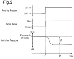
Fig. 2 is a timing chart showing changes in canister pressure after starting a purging process; -
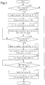
Fig. 3 is a flowchart showing the process sequence of negative pressure reduction control of the embodiment; and -
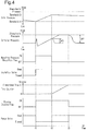
Fig. 4 is a timing chart showing the operation of the negative pressure reduction control of the embodiment. - Referring to
Figs. 1 to 4 , one embodiment of a fuel vapor treatment system will now be described. In the following description, "pressures" other than "negative pressure" refer to absolute pressures rather than gauge pressures. -
Fig. 1 schematically shows the structure of avehicle engine 10 that uses the fuel vapor treatment system of the present embodiment. - As shown in
Fig. 1 , the internal combustion engine (hereinafter referred to as engine) 10 includes afuel tank 21, which stores fuel, afuel injection valve 12, which injects fuel into acombustion chamber 11, and aspark plug 13, which ignites mixture gas of intake air and the injected fuel. The fuel in thefuel tank 21 is sent to thefuel injection valve 12 through a fuel supply passage, which is connected to thefuel tank 21. Thefuel tank 21 includes a tank pressure sensor 56 that detects tank pressure PT, which is the pressure in thefuel tank 21. - The
combustion chamber 11 is connected to anintake passage 14 and anexhaust passage 15. Asurge tank 16, which is a part of theintake passage 14, is located in an intermediate section of theintake passage 14. Athrottle valve 17, which adjusts the amount of intake air, is located upstream of thesurge tank 16 in theintake passage 14. - The
engine 10 includes a fuelvapor treatment system 30, which limits emission of fuel vapor (hereinafter referred to as vapor) generated in thefuel tank 21 into the atmosphere. The fuelvapor treatment system 30 includes acanister 31, which adsorbs vapor generated in thefuel tank 21. - A
vapor passage 32 provides communication between thecanister 31 and thefuel tank 21. Anisolation valve 45 is located in an intermediate section of thevapor passage 32 to open and close thevapor passage 32. - A
purge passage 33 provides communication between thecanister 31 and thesurge tank 16. Apurge valve 35 is located in an intermediate section of thepurge passage 33 to adjust the flow rate of vapor flowing through thepurge passage 33. - The
canister 31 is connected to an outsideair introduction passage 36, which introduces outside air into thecanister 31. The open end of the outsideair introduction passage 36 includes anair filter 50. Apump module 40 is located in an intermediate section of the outsideair introduction passage 36. - The
pump module 40 includes an air pump that reduces the pressure in thecanister 31, a switching valve that opens and closes the outsideair introduction passage 36, an orifice, and acanister pressure sensor 57 that detects canister pressure PC, which is the pressure in thecanister 31. During operation of theengine 10, the air pump of thepump module 40 is off, and the switching valve is maintained to open the outsideair introduction passage 36, in other words, maintained to permit introduction of outside air into thecanister 31. When anignition switch 58 is turned off to stop theengine 10, various sequences are executed using thepump module 40 to perform an anomaly diagnosis on the fuelvapor treatment system 30. - The vapor generated in the
fuel tank 21 is introduced into thecanister 31 from thefuel tank 21 through thevapor passage 32 and temporarily captured by an adsorbent of thecanister 31. Since there is a limit to the amount of vapor that thecanister 31 can adsorb, the fuelvapor treatment system 30 performs a purging process when predetermined conditions are satisfied. In the purging process, thepurge valve 35 is opened while theengine 10 is running, desorbing vapor from thecanister 31. The desorbed vapor is introduced into thesurge tank 16 through thepurge passage 33 and then burned in thecombustion chamber 11. - A
controller 60, which serves as a control unit, controls the fuelvapor treatment system 30 and theengine 10. Thecontroller 60 is a processor or processing circuitry that includes a central processing unit (CPU), a read-only memory (ROM), a random-access memory (RAM), a backup RAM, an external input circuit, and an external output circuit. - The
controller 60 is connected to various sensors, which detect the running conditions, for example, of theengine 10, the tank pressure sensor 56, thecanister pressure sensor 57, theignition switch 58, which is operated by the driver of the vehicle, and other devices. Thecontroller 60 performs various control processes on the fuelvapor treatment system 30 and theengine 10 based on the signals received from such sensors and switches. - As one of the control processes, the
controller 60 performs, while theengine 10 is running, a clogging diagnosis process that identifies whether thepurge passage 33 is clogged. Specifically, the clogging diagnosis process is performed when a purging process starts. The clogging diagnosis process will be outlined below. - As shown in
Fig. 2 , when the purging process starts and thepurge valve 35 is opened at time t1, the negative pressure in theintake passage 14 acts on the pressure in thecanister 31, which is equivalent to the atmospheric pressure. This significantly decreases the canister pressure PC after time t1 compared to before starting the purging process. However, if thepurge passage 33 is clogged, the amount of vapor flowing through thepurge passage 33 is reduced, lowering the decrease amount of the canister pressure PC after starting the purging process. - To perform the clogging diagnosis process, the
controller 60 first calculates a pressure decrease amount ΔP in thecanister 31 that results from execution of the purging process. Specifically, the pressure decrease amount ΔP is the absolute value of the difference between the canister pressure PC that is detected immediately before starting the purging process and the canister pressure PC that is detected when the pressure change becomes stable after starting the purge process. Then, thecontroller 60 compares the calculated pressure decrease amount ΔP and a predetermined threshold E and identifies that thepurge passage 33 is clogged if the pressure decrease amount ΔP is less than the threshold E. - The
controller 60 normally keeps theisolation valve 45 closed to minimize vapor flowing from thefuel tank 21 into thecanister 31. However, when theisolation valve 45 is kept closed, consumption of the fuel or decrease in the fuel temperature in thefuel tank 21 generates negative pressure (pressure lower than the atmospheric pressure) in thefuel tank 21. Excessive pressure decrease in thefuel tank 21 generates bubbles in the fuel in thefuel tank 21. Such bubbles may enter the fuel line. - Thus, the
controller 60 performs negative pressure reduction control to reduce negative pressure in thefuel tank 21.Fig. 3 shows the process sequence for the negative pressure reduction control. - As shown in
Fig. 3 , thecontroller 60 first determines whether the tank pressure PT is less than or equal to a threshold A (S100). The threshold A is a pressure that is less than the atmospheric pressure. More specifically, the threshold A is a pressure that is slightly greater than the value of the tank pressure PT at which bubbles start to form during the process in which the fuel the pressure in thefuel tank 21 is gradually reduced. The threshold A serves as a first pressure. - If the tank pressure PT is greater than the threshold A (S100: NO), the
controller 60 ends the process since there is no probability that bubbles will form in the fuel in thefuel tank 21. When the condition is not satisfied in step S100, theisolation valve 45 remains closed in the normal state. - If the tank pressure PT is less than or equal to the threshold A (S100: YES), the
controller 60 sets a negative pressure reduction flag FN to ON (S110). The negative pressure reduction flag FN, which is OFF in the default setting, is set to ON when reduction in the negative pressure in thefuel tank 21, that is, increase in the absolute pressure in thefuel tank 21, is required. - When the negative pressure reduction flag FN is set to ON, the
controller 60 then sets a purging disable flag FP to ON. The purging disable flag FP, which is set to OFF in the default setting, is set to ON when the purging process needs to be disabled. - After the purging disable flag FP is set to ON, the
controller 60 cuts off purging by closing the purge valve 35 (S130). This disables the purging process. - Since the negative pressure reduction flag FN is ON, the
controller 60 then performs the negative pressure reduction process by opening the isolation valve 45 (S140). - Then, the
controller 60 determines whether the tank pressure PT after opening theisolation valve 45 is greater than or equal to a threshold B. The threshold B is a pressure that is greater than the threshold A and is less than the atmospheric pressure by a predetermined pressure α. The atmospheric pressure may simply be the standard atmosphere. More preferably, the threshold B may be a variable that is set to be greater than the threshold A and less than the actual atmospheric pressure by the predetermined pressure α. The actual atmospheric pressure may be detected by connecting thecontroller 60 to a sensor that detects the atmospheric pressure. The threshold B serves as a second pressure. - If the tank pressure PT is less than the threshold B (S150: NO), the
controller 60 repeats the processes of step S140 and step S150 and continues the negative pressure reduction process until the tank pressure PT reaches the threshold B. In other words, thecontroller 60 keeps theisolation valve 45 open. - If the tank pressure PT is greater than or equal to the threshold B (S150: YES), the
controller 60 sets the negative pressure reduction flag FN to OFF (S160). When the negative pressure reduction flag FN is set to OFF, thecontroller 60 closes theisolation valve 45 and ends the negative pressure reduction process (S170). - When the negative pressure reduction process ends, the
controller 60 starts measuring a time counter CT (S180). The time counter CT is a value that indicates the time elapsed since the negative pressure reduction process ends, that is, since theisolation valve 45 is closed. - Then, the
controller 60 determines whether the time counter CT becomes greater than or equal to a prescribed time C (S190). The prescribed time C is set as follows. - If the tank pressure PT is determined to be greater than or equal to the threshold B in step S150, the process of step S170 is performed to close the
isolation valve 45. When theisolation valve 45 is open, the communication between thefuel tank 21 and thecanister 31 through thevapor passage 32 renders the canister pressure PC negative pressure. In addition, the threshold B is less than the atmospheric pressure. Thus, immediately after closing theisolation valve 45, negative pressure is present in thecanister 31. However, after closing theisolation valve 45, the outside air introduced into thecanister 31 through the outsideair introduction passage 36 gradually increases the pressure in thecanister 31 toward the atmospheric pressure. - As such, the prescribed time C is set to the time required for the canister pressure PC to reach the atmospheric pressure after closing the
isolation valve 45 in step S170. For example, when the minimum time required for the canister pressure PC to reach the atmospheric pressure after closing theisolation valve 45 in step S170 is a minimum time C1, the prescribed time C is set to be the time obtained by adding a predetermined allowance time β to the minimum time C1. Alternatively, the prescribed time C may simply be set to the minimum time C1. In the description above, the atmospheric pressure refers to a pressure near the atmospheric pressure or, more specifically, a pressure that is near the atmospheric pressure and does not affect the determination result of the clogging diagnosis process. - If the time counter CT is less than the prescribed time C (S190: NO), the
controller 60 repeats the process of step S190 until the time counter CT reaches the prescribed time C. - If the time counter CT is greater than or equal to the prescribed time C (S190: YES), the
controller 60 resets the time counter CT to 0 (S200). Thecontroller 60 then sets the purging disable flag FP to OFF (S210) and ends the process. - Alternatively, the
controller 60 may set the purging disable flag FP to OFF and then reset the time counter CT to 0 when the time counter CT is greater than or equal to the prescribed time C. - Referring to
Fig. 4 , the operation of the negative pressure reduction process will now be described. Before time t1 shown inFig. 4 , the purging process is active, and thus thepurge valve 35 is open. Consequently, the canister pressure PC is decreased to be equivalent to the pressure of the intake air in thesurge tank 16. In addition, theisolation valve 45 is closed to seal thefuel tank 21 before time t1. - As shown in
Fig. 4 , consumption of the fuel or decrease in the fuel temperature in thefuel tank 21 gradually decreases the tank pressure PT. When the tank pressure PT is decreased to the threshold A at time t1, the negative pressure reduction flag FN is set to ON and the purging disable flag FP is also set to ON. - Setting the purging disable flag FP to ON closes the
purge valve 35 and disables the purging process. In addition, setting the negative pressure reduction flag FN to ON opens theisolation valve 45. - At time t1, the
purge valve 35 is closed to shut off the communication between thesurge tank 16 and thecanister 31, momentarily increasing the canister pressure PC. However, theisolation valve 45 is then immediately opened to establish communication between thefuel tank 21 and thecanister 31, rapidly decreasing the canister pressure PC toward the tank pressure PT. - The outside air entering the outside
air introduction passage 36 is drawn into thefuel tank 21 through thecanister 31 and thevapor passage 32. The tank pressure PT and the canister pressure PC gradually increase toward the atmospheric pressure accordingly. - The tank pressure PT thus increases from the pressure of the threshold A after time t1, thereby limiting formation of bubbles in the fuel, which would otherwise be caused by decrease in the pressure in the
fuel tank 21. - When the tank pressure PT increases to the threshold B at time t2, the negative pressure reduction flag FN is set to OFF and the
isolation valve 45 is closed. Closing theisolation valve 45 stops the introduction of outside air into thefuel tank 21, stopping increase in the tank pressure PT. After time t2, consumption of the fuel or decrease in the fuel temperature in thefuel tank 21 gradually decreases the tank pressure PT again from the pressure of the threshold B. - Measurement of the time counter CT starts when the
isolation valve 45 is closed at time t2. Thus, the value of the time counter CT gradually increases after time t2. - When the time counter CT reaches the prescribed time C at time t3, the time counter CT is reset to 0 and the purging disable flag FP is set to OFF. At time t3, since the time counter CT has reached the prescribed time C, the canister pressure PC is the atmospheric pressure.
- If the purging process is requested at time t3, the purging process is performed without being disabled since the purging disable flag FP is OFF. This opens the
purge valve 35. When the purging process starts, the clogging diagnosis process is performed. At time t3, the canister pressure PC is the atmospheric pressure as described above. Thus, the pressure decrease amount ΔP2 in thecanister 31, which is calculated after time t3, is sufficiently large compared, for example, to the pressure decrease amount ΔP1 in thecanister 31, which is calculated when a purging process starts under the condition that the canister pressure PC is negative pressure as indicated by the long dashed double-short dashed line inFig. 4 . - In the negative pressure reduction control, an isolation valve operation process is first performed to open the
isolation valve 45 when the tank pressure PT is less than or equal to the threshold A, which is less than the atmospheric pressure, and to close theisolation valve 45 when the tank pressure PT is greater than or equal to the threshold B, which is greater than the threshold A and less than the atmospheric pressure. This maintains the pressure in thefuel tank 21 at a pressure between the threshold A, which is less than the atmospheric pressure, and the threshold B, which is greater than the threshold A and less than the atmospheric pressure, in other words, at negative pressure. - The present embodiment seals the
fuel tank 21 by keeping theisolation valve 45 closed, and the pressure in the sealedfuel tank 21 remains less than the atmospheric pressure. This limits leakage of vapor from thefuel tank 21, in other words, confines vapor within thefuel tank 21. - Further, opening the
isolation valve 45 returns the vapor adsorbed by thecanister 31 to thefuel tank 21 through thevapor passage 32 together with the outside air entering the outsideair introduction passage 36. Returning the vapor from thecanister 31 to thefuel tank 21 reduces the amount of vapor adsorbed by thecanister 31. This gives thecanister 31 room for adsorbing vapor. Thus, thecanister 31 maintains its adsorption capacity even when the purging process is performed less frequently. - In addition, in the negative pressure reduction control, a purging disabling process is performed to disable the purging process by setting the purging disable flag FP to ON in the period from time t1, at which the
isolation valve 45 is opened, to time t3, at which the prescribed time C has elapsed since theisolation valve 45 is closed. - The following effects are achieved by disabling the purging process between time t1 and time t2 in the execution period of the purging disabling process, in other words, by keeping the
purge valve 35 closed while theisolation valve 45 is open. - If the
isolation valve 45 and thepurge valve 35 are both open, thefuel tank 21 is in communication with thesurge tank 16. This may move air into thefuel tank 21 from thesurge tank 16 when the tank pressure PT is less than the pressure in thesurge tank 16. Such a flow of air into thefuel tank 21 from thesurge tank 16 affects the air-fuel ratio of the mixture gas and the amount of fuel vapor introduced into thesurge tank 16 and thus into theintake passage 14, for example. This may deteriorate the combustion state of mixture gas. - In contrast, when the purging disabling process is performed, the purging process is disabled while the
isolation valve 45 is open from time t1 to time t2. Thus, thepurge valve 35 remains closed while theisolation valve 45 is open. This limits entry of air into thefuel tank 21 from thesurge tank 16 caused by opening theisolation valve 45. - The following effects are achieved by disabling the purging process between time t2 and time t3 in the execution period of the purging disabling process, in other words, by disabling the purging process in the period from when the
isolation valve 45 is closed to when the prescribed time C has elapsed since theisolation valve 45 is closed. - The isolation valve operation process closes the
isolation valve 45 when the tank pressure PT reaches the threshold B (time t2), and the canister pressure PC immediately after closing theisolation valve 45 is a pressure lower than the atmospheric pressure (negative pressure). Thus, as indicated by the long dashed double-short dashed line inFig. 4 , if a purging process were to start at time t2 by opening thepurge valve 35 immediately after closing theisolation valve 45, the canister pressure PC immediately before performing such a purging process would be negative pressure. In this case, the pressure decrease amount ΔP1 in thecanister 31 that results from starting the purging process is small. Consequently, the pressure decrease amount ΔP1 may not cross the threshold E in the clogging diagnosis process that is performed when starting the purging process, causing theunclogged purge passage 33 to be wrongly identified as clogged. - In contrast, the negative pressure reduction control disables the purging process at least in the period from when the
isolation valve 45 is closed to when the prescribed time C has elapsed since theisolation valve 45 is closed. That is, the purging process is disabled as long as there is a possibility that negative pressure is present in thecanister 31. Thus, when the pressure decrease amount ΔP in thecanister 31 that results from execution of a purging process would be small, the clogging diagnosis process, which determines whether thepurge passage 33 is clogged based on the pressure decrease amount ΔP, is not performed. This reduces situations where theunclogged purge passage 33 is wrongly identified as clogged. - The above described embodiment has the following advantages.
- (1) The isolation valve operation process maintains the pressure in the
fuel tank 21 at negative pressure. Further, the purging process is disabled in the period from when theisolation valve 45 is closed to when the prescribed time C has elapsed since theisolation valve 45 is closed. Thus, while the purging process is disabled, the clogging diagnosis process, which identifies whether thepurge passage 33 is clogged based on the pressure decrease amount ΔP in thecanister 31 that results from execution of the purging process, is disabled. This reduces situations where theunclogged purge passage 33 is wrongly identified as clogged. - (2) The prescribed time C is set to the time required for the pressure in the
canister 31 to reach the atmospheric pressure after theisolation valve 45 is closed. Thus, the purging process is disabled until the pressure in thecanister 31 reaches the atmospheric pressure. This reduces wrong diagnoses regarding clogging of thepurge passage 33 in a suitable manner. - (3) The purging process is disabled in the period from when the isolation valve operation process opens the
isolation valve 45 to when the prescribed time C has elapsed since the isolation valve operation process closes theisolation valve 45. This limits entry of air into thefuel tank 21 from thesurge tank 16 caused by opening theisolation valve 45. - The above described embodiment may be modified as follows.
- In the above illustrated embodiment, the purging process is disabled in the period from when the isolation valve operation process opens the
isolation valve 45 to when the prescribed time C has elapsed since the isolation valve operation process closes the isolation valve 45 (period from time t1 to time t3 shown inFig. 4 ). Instead, the purging process may be disabled at least in the period from when theisolation valve 45 is closed to when the prescribed time C has elapsed since theisolation valve 45 is closed (period from time t2 to time t3 shown inFig. 4 ). Such an operation achieves the advantages described above excluding advantage (3). - The
purge passage 33 is connected to thesurge tank 16. However, thepurge passage 33 may be connected to theintake passage 14 at any location downstream of thethrottle valve 17. - Therefore, the present examples and embodiments are to be considered as illustrative and not restrictive and the disclosure is not to be limited to the details given herein, but may be modified within the scope and equivalence of the appended claims.
Claims (6)
- A fuel vapor treatment system comprising:a fuel tank (21) for storing fuel for an internal combustion engine (10);a canister (31) for adsorbing fuel vapor generated in the fuel tank (21);a vapor passage (32) that provides communication between the fuel tank (21) and the canister (31);a purge passage (33) that provides communication between the canister (31) and an intake passage (14) of the internal combustion engine (10);an isolation valve (45) for opening and closing the vapor passage (32);a purge valve (35) for adjusting a flow rate of fuel vapor flowing through the purge passage (33);an outside air introduction passage (36) for introducing outside air into the canister (31);a tank pressure sensor (56) for detecting pressure (TP) in the fuel tank (21);a canister pressure sensor (57) for detecting pressure (PC) in the canister (31); anda control unit (60) that is configured to perform:a purging process, in which the control unit (60) opens the purge valve (35) while the internal combustion engine (10) is running to introduce the fuel vapor adsorbed by the canister (31) into the intake passage (14); anda diagnosis process, in which the control unit (60) identifies clogging of the purge passage (33) based on a decrease amount of the pressure (PC) in the canister (31) that results from execution of the purging process,the fuel vapor treatment system being characterized in that the control unit (60) is configured to further perform:an isolation valve operation process, in which the control unit (60) opens the isolation valve (45) when the pressure (TP) in the fuel tank (21) is less than or equal to a first pressure (A), which is less than an atmospheric pressure, and the control unit (60) closes the isolation valve (45) when the pressure (TP) in the fuel tank (21) is greater than or equal to a second pressure (B), which is greater than the first pressure (A) and less than the atmospheric pressure; anda purging disabling process, in which the control unit (60) disables the purging process at least in a period from when the control unit (60) closes the isolation valve (45) in the isolation valve operation process to when a prescribed time has elapsed from the closing of the isolation valve (45).
- The fuel vapor treatment system according to claim 1, wherein the prescribed time is set to a time required for the pressure (PC) in the canister (31) to reach the atmospheric pressure after the isolation valve (45) is closed.
- The fuel vapor treatment system according to claim 1 or 2, wherein the control unit (60) is configured to perform the purging disabling process in a period from when the control unit (60) opens the isolation valve (45) in the isolation valve operation process to when the prescribed time has elapsed from the closing of the isolation valve (45).
- A method for controlling a vapor treatment system comprising:a fuel tank (21) for storing fuel for an internal combustion engine (10);a canister (31) for adsorbing fuel vapor generated in the fuel tank (21);a vapor passage (32) that provides communication between the fuel tank (21) and the canister (31);a purge passage (33) that provides communication between the canister (31) and an intake passage (14) of the internal combustion engine (10); andan outside air introduction passage (36) for introducing outside air into the canister (31),the method comprising:a purging process, in which the purge passage (33) is opened while the internal combustion engine (10) is running to introduce the fuel vapor adsorbed by the canister (31) into the intake passage (14); anda diagnosis process, in which clogging of the purge passage (33) is identified based on a decrease amount of the pressure (PC) in the canister (31) that results from execution of the purging process,the method being characterized by further comprising:an isolation operation process, in which the vapor passage (32) is opened when the pressure (TP) in the fuel tank (21) is less than or equal to a first pressure (A), which is less than an atmospheric pressure, and the vapor passage (32) is closed when the pressure (TP) in the fuel tank (21) is greater than or equal to a second pressure (B), which is greater than the first pressure (A) and less than the atmospheric pressure; anda purging disabling process, in which the purging process is disabled at least in a period from when closing the vapor passage (32) in the isolation operation process to when a prescribed time has elapsed from the closing of the vapor passage (32).
- The method according to claim 4, wherein the prescribed time is set to a time required for the pressure (PC) in the canister (31) to reach the atmospheric pressure after the vapor passage (32) is closed.
- The method according to claim 4 or 5, wherein the purging disabling process is performed in a period from when opening the vapor passage (32) in the isolation operation process to when the prescribed time has elapsed from the closing of the vapor passage (32).
Applications Claiming Priority (1)
| Application Number | Priority Date | Filing Date | Title |
|---|---|---|---|
| JP2015047244A JP6337806B2 (en) | 2015-03-10 | 2015-03-10 | Evaporative fuel processing equipment |
Publications (2)
| Publication Number | Publication Date |
|---|---|
| EP3067545A1 true EP3067545A1 (en) | 2016-09-14 |
| EP3067545B1 EP3067545B1 (en) | 2017-09-13 |
Family
ID=55443174
Family Applications (1)
| Application Number | Title | Priority Date | Filing Date |
|---|---|---|---|
| EP16157762.2A Not-in-force EP3067545B1 (en) | 2015-03-10 | 2016-02-29 | Fuel vapor treatment system |
Country Status (4)
| Country | Link |
|---|---|
| US (1) | US10006411B2 (en) |
| EP (1) | EP3067545B1 (en) |
| JP (1) | JP6337806B2 (en) |
| CN (1) | CN105971774B (en) |
Families Citing this family (17)
| Publication number | Priority date | Publication date | Assignee | Title |
|---|---|---|---|---|
| FR3035213B1 (en) * | 2015-04-14 | 2018-08-10 | Continental Automotive France | PRESSURE CONTROL METHOD INCLUDING BOILING DETECTION |
| FR3044612B1 (en) * | 2015-12-07 | 2019-08-23 | Continental Automotive France | CONTROL OF DEPRESSURIZATION OF A FUEL TANK OF A MOTOR VEHICLE |
| JP6316347B2 (en) * | 2016-07-13 | 2018-04-25 | 本田技研工業株式会社 | Blockage detection apparatus and blockage detection method |
| JP6634997B2 (en) * | 2016-10-07 | 2020-01-22 | 株式会社デンソー | Evaporative fuel processing system |
| JP6683594B2 (en) * | 2016-12-21 | 2020-04-22 | トヨタ自動車株式会社 | Evaporative fuel processor |
| US10767600B2 (en) * | 2016-12-22 | 2020-09-08 | Polaris Industries Inc. | Evaporative emissions control for a vehicle |
| KR102335377B1 (en) * | 2017-04-27 | 2021-12-06 | 현대자동차주식회사 | Method for diagnosing pcsv |
| JP6786450B2 (en) * | 2017-07-05 | 2020-11-18 | 愛三工業株式会社 | Evaporative fuel processing equipment |
| JP6801597B2 (en) * | 2017-07-21 | 2020-12-16 | トヨタ自動車株式会社 | Internal combustion engine control device |
| JP6619787B2 (en) * | 2017-10-20 | 2019-12-11 | 本田技研工業株式会社 | Occlusion diagnostic device |
| JP6484685B1 (en) * | 2017-10-20 | 2019-03-13 | 本田技研工業株式会社 | Fuel remaining amount estimation device and fuel vapor sealed system abnormality diagnosis device |
| JP6854233B2 (en) * | 2017-11-16 | 2021-04-07 | 本田技研工業株式会社 | Blockage detection device and blockage detection method |
| EP3498515A1 (en) * | 2017-12-18 | 2019-06-19 | Plastic Omnium Advanced Innovation and Research | Method for determining the thermodynamic state of the fuel in a fuel system |
| CN111472899B (en) * | 2019-01-23 | 2021-12-07 | 比亚迪股份有限公司 | Leakage diagnosis method and device for fuel oil evaporative emission system |
| JP2020133503A (en) * | 2019-02-20 | 2020-08-31 | 愛三工業株式会社 | Evaporation fuel treatment device |
| CN114060181B (en) * | 2021-10-14 | 2024-03-19 | 江苏大学 | Vehicle-mounted oil gas evaporation, condensation and recovery system and control method thereof |
| CN115628166B (en) * | 2022-12-23 | 2023-03-31 | 中国第一汽车股份有限公司 | Oil tank pressure control method, device, equipment and medium applied to vehicle |
Citations (5)
| Publication number | Priority date | Publication date | Assignee | Title |
|---|---|---|---|---|
| JP2010242723A (en) | 2009-04-10 | 2010-10-28 | Toyota Motor Corp | Control device for fuel tank system |
| US20110168140A1 (en) * | 2010-05-28 | 2011-07-14 | Ford Global Technologies, Llc | Method and system for fuel vapor control |
| US20110253110A1 (en) * | 2010-04-15 | 2011-10-20 | Toyota Jidosha Kabushiki Kaisha | Vaporized fuel processing device for internal combustion engine |
| US20130008415A1 (en) * | 2011-07-07 | 2013-01-10 | Mitsubishi Jidosha Kogyo Kabushiki Kaisha | Evaporative emission control device for an internal combustion engine |
| US20140318506A1 (en) * | 2013-04-30 | 2014-10-30 | Ford Global Technologies, Llc | Air intake system hydrocarbon trap purging |
Family Cites Families (28)
| Publication number | Priority date | Publication date | Assignee | Title |
|---|---|---|---|---|
| JP3096377B2 (en) * | 1993-06-28 | 2000-10-10 | 本田技研工業株式会社 | Evaporative fuel processor for internal combustion engines |
| JPH0783124A (en) * | 1993-09-16 | 1995-03-28 | Nissan Motor Co Ltd | Diagnostic device for fuel evaporative emission control device |
| JP3630711B2 (en) * | 1994-01-31 | 2005-03-23 | 富士重工業株式会社 | Vehicular fuel tank internal pressure adjustment device |
| US5494021A (en) * | 1994-09-15 | 1996-02-27 | Nissan Motor Co., Ltd. | Evaporative purge monitoring method and system |
| JP3627879B2 (en) * | 1995-11-20 | 2005-03-09 | マツダ株式会社 | Evaporative fuel supply device failure detection device |
| JP3339547B2 (en) * | 1996-07-19 | 2002-10-28 | トヨタ自動車株式会社 | Failure diagnosis device for evaporation purge system |
| JP3401778B2 (en) * | 1996-08-12 | 2003-04-28 | トヨタ自動車株式会社 | Failure diagnosis device for evaporation purge system |
| JPH10259765A (en) * | 1997-01-17 | 1998-09-29 | Nippon Soken Inc | Fuel tank internal pressure control device and tank internal pressure control valve |
| US6041761A (en) * | 1997-05-30 | 2000-03-28 | Honda Giken Kogyo Kabushiki Kaisha | Evaporative emission control system for internal combustion engines |
| US6192742B1 (en) * | 1997-11-17 | 2001-02-27 | Denso Corporation | More reliable leakage diagnosis for evaporated gas purge system |
| JP2001193582A (en) | 1999-12-28 | 2001-07-17 | Toyota Motor Corp | Failure diagnosis device for fuel vapor purge system |
| US6564780B2 (en) * | 2000-06-23 | 2003-05-20 | Toyota Jidosha Kabushiki Kaisha | Diagnostic apparatus and method for fuel vapor purge system |
| JP2002081349A (en) | 2000-06-23 | 2002-03-22 | Toyota Motor Corp | Failure diagnosis device for fuel vapor purge system |
| JP4080697B2 (en) * | 2001-01-19 | 2008-04-23 | 本田技研工業株式会社 | Automatic engine stop / start control device for vehicle |
| JP3975847B2 (en) * | 2002-07-15 | 2007-09-12 | 日産自動車株式会社 | Fuel evaporative gas processing equipment |
| JP4419740B2 (en) * | 2004-07-23 | 2010-02-24 | トヨタ自動車株式会社 | In-tank canister system failure diagnosis apparatus and failure diagnosis method |
| US8573255B2 (en) * | 2009-04-22 | 2013-11-05 | Eaton Corporation | Valve assembly for high-pressure fluid reservoir |
| JP2011021505A (en) * | 2009-07-14 | 2011-02-03 | Aisan Industry Co Ltd | Evaporated fuel processing device |
| US8447495B2 (en) * | 2010-05-28 | 2013-05-21 | Ford Global Technologies, Llc | Method and system for fuel vapor control |
| CN103228898B (en) * | 2010-09-24 | 2017-07-28 | 凯莱汽车公司 | Vapo(u)rability and the system of refuelling emission control again for vehicle |
| JP5709573B2 (en) * | 2011-02-18 | 2015-04-30 | 本田技研工業株式会社 | Evaporative fuel processing equipment |
| JP5556702B2 (en) * | 2011-03-04 | 2014-07-23 | 三菱自動車工業株式会社 | Fuel evaporative emission control device for internal combustion engine |
| WO2012131885A1 (en) | 2011-03-28 | 2012-10-04 | トヨタ自動車株式会社 | Fuel tank system |
| JP5761515B2 (en) | 2011-10-27 | 2015-08-12 | 三菱自動車工業株式会社 | Fuel evaporative emission control device |
| US9027533B2 (en) * | 2012-07-26 | 2015-05-12 | Ford Global Technologies, Llc | Method and system for fuel system control |
| JP5724983B2 (en) * | 2012-10-11 | 2015-05-27 | 株式会社デンソー | Fuel vapor leak detection device |
| JP5527391B2 (en) * | 2012-11-28 | 2014-06-18 | 三菱自動車工業株式会社 | Fuel evaporative emission control device for internal combustion engine |
| US9341147B2 (en) * | 2013-03-07 | 2016-05-17 | Ford Global Technologies, Llc | Engine-off refueling detection method |
-
2015
- 2015-03-10 JP JP2015047244A patent/JP6337806B2/en active Active
-
2016
- 2016-02-25 US US15/052,955 patent/US10006411B2/en active Active
- 2016-02-29 EP EP16157762.2A patent/EP3067545B1/en not_active Not-in-force
- 2016-03-04 CN CN201610124701.5A patent/CN105971774B/en not_active Expired - Fee Related
Patent Citations (5)
| Publication number | Priority date | Publication date | Assignee | Title |
|---|---|---|---|---|
| JP2010242723A (en) | 2009-04-10 | 2010-10-28 | Toyota Motor Corp | Control device for fuel tank system |
| US20110253110A1 (en) * | 2010-04-15 | 2011-10-20 | Toyota Jidosha Kabushiki Kaisha | Vaporized fuel processing device for internal combustion engine |
| US20110168140A1 (en) * | 2010-05-28 | 2011-07-14 | Ford Global Technologies, Llc | Method and system for fuel vapor control |
| US20130008415A1 (en) * | 2011-07-07 | 2013-01-10 | Mitsubishi Jidosha Kogyo Kabushiki Kaisha | Evaporative emission control device for an internal combustion engine |
| US20140318506A1 (en) * | 2013-04-30 | 2014-10-30 | Ford Global Technologies, Llc | Air intake system hydrocarbon trap purging |
Also Published As
| Publication number | Publication date |
|---|---|
| JP2016166580A (en) | 2016-09-15 |
| EP3067545B1 (en) | 2017-09-13 |
| CN105971774A (en) | 2016-09-28 |
| JP6337806B2 (en) | 2018-06-06 |
| CN105971774B (en) | 2018-09-14 |
| US20160265480A1 (en) | 2016-09-15 |
| US10006411B2 (en) | 2018-06-26 |
Similar Documents
| Publication | Publication Date | Title |
|---|---|---|
| EP3067545B1 (en) | Fuel vapor treatment system | |
| US7383826B2 (en) | Fuel vapor treatment apparatus, system having the same, method for operating the same | |
| US9181906B2 (en) | Fuel vapor processing systems | |
| US7610906B2 (en) | Fuel vapor treatment system | |
| US20150159567A1 (en) | Vaporized fuel processing apparatus | |
| US10907592B2 (en) | Vaporized fuel treatment device and learning method of valve opening start position of sealing valve in vaporized fuel treatment device | |
| US10428769B2 (en) | Fuel vapor treatment apparatus | |
| US20150330337A1 (en) | Fuel vapor processing apparatus | |
| JP2015214918A (en) | Evaporative fuel treatment device | |
| US9850855B2 (en) | Fuel evaporative gas emission control apparatus | |
| CN107735562A (en) | Evaporative Fuel Treatment Unit | |
| JP2006177199A (en) | Evaporative fuel treatment device leak diagnosis device | |
| US20070062495A1 (en) | Evaporative fuel treatment system | |
| JP2005330924A (en) | Evaporative fuel control device for internal combustion engine | |
| JP2615939B2 (en) | Self-diagnosis device in fuel evaporative gas diffusion prevention device | |
| JP4526901B2 (en) | Evaporative fuel processing system diagnostic device | |
| JP4481054B2 (en) | Evaporative fuel processing system diagnostic device | |
| US7080548B2 (en) | Diagnostic device of evaporated fuel processing system and the method thereof | |
| US7168302B2 (en) | Diagnostic device of evaporated fuel processing system and the method thereof | |
| JPH0726574B2 (en) | Air-fuel ratio controller for engine | |
| JP2003343364A (en) | Evaporative fuel processor for engine | |
| US20260063085A1 (en) | Diagnostic apparatus for engine system | |
| JP2007085230A (en) | Refueling port opening detection device for evaporative fuel processing system | |
| JP2007092585A (en) | Leak diagnostic device for evaporative fuel processing system | |
| JP3196428B2 (en) | Air-fuel ratio control device for internal combustion engine |
Legal Events
| Date | Code | Title | Description |
|---|---|---|---|
| PUAI | Public reference made under article 153(3) epc to a published international application that has entered the european phase |
Free format text: ORIGINAL CODE: 0009012 |
|
| 17P | Request for examination filed |
Effective date: 20160229 |
|
| AK | Designated contracting states |
Kind code of ref document: A1 Designated state(s): AL AT BE BG CH CY CZ DE DK EE ES FI FR GB GR HR HU IE IS IT LI LT LU LV MC MK MT NL NO PL PT RO RS SE SI SK SM TR |
|
| AX | Request for extension of the european patent |
Extension state: BA ME |
|
| GRAP | Despatch of communication of intention to grant a patent |
Free format text: ORIGINAL CODE: EPIDOSNIGR1 |
|
| STAA | Information on the status of an ep patent application or granted ep patent |
Free format text: STATUS: GRANT OF PATENT IS INTENDED |
|
| INTG | Intention to grant announced |
Effective date: 20170411 |
|
| GRAS | Grant fee paid |
Free format text: ORIGINAL CODE: EPIDOSNIGR3 |
|
| GRAA | (expected) grant |
Free format text: ORIGINAL CODE: 0009210 |
|
| STAA | Information on the status of an ep patent application or granted ep patent |
Free format text: STATUS: THE PATENT HAS BEEN GRANTED |
|
| AK | Designated contracting states |
Kind code of ref document: B1 Designated state(s): AL AT BE BG CH CY CZ DE DK EE ES FI FR GB GR HR HU IE IS IT LI LT LU LV MC MK MT NL NO PL PT RO RS SE SI SK SM TR |
|
| REG | Reference to a national code |
Ref country code: GB Ref legal event code: FG4D |
|
| REG | Reference to a national code |
Ref country code: CH Ref legal event code: EP |
|
| REG | Reference to a national code |
Ref country code: IE Ref legal event code: FG4D |
|
| REG | Reference to a national code |
Ref country code: AT Ref legal event code: REF Ref document number: 928414 Country of ref document: AT Kind code of ref document: T Effective date: 20171015 |
|
| REG | Reference to a national code |
Ref country code: DE Ref legal event code: R096 Ref document number: 602016000361 Country of ref document: DE |
|
| REG | Reference to a national code |
Ref country code: DE Ref legal event code: R084 Ref document number: 602016000361 Country of ref document: DE |
|
| REG | Reference to a national code |
Ref country code: GB Ref legal event code: 746 Effective date: 20171124 |
|
| REG | Reference to a national code |
Ref country code: FR Ref legal event code: PLFP Year of fee payment: 3 |
|
| REG | Reference to a national code |
Ref country code: NL Ref legal event code: MP Effective date: 20170913 |
|
| REG | Reference to a national code |
Ref country code: LT Ref legal event code: MG4D |
|
| PG25 | Lapsed in a contracting state [announced via postgrant information from national office to epo] |
Ref country code: HR Free format text: LAPSE BECAUSE OF FAILURE TO SUBMIT A TRANSLATION OF THE DESCRIPTION OR TO PAY THE FEE WITHIN THE PRESCRIBED TIME-LIMIT Effective date: 20170913 Ref country code: NO Free format text: LAPSE BECAUSE OF FAILURE TO SUBMIT A TRANSLATION OF THE DESCRIPTION OR TO PAY THE FEE WITHIN THE PRESCRIBED TIME-LIMIT Effective date: 20171213 Ref country code: LT Free format text: LAPSE BECAUSE OF FAILURE TO SUBMIT A TRANSLATION OF THE DESCRIPTION OR TO PAY THE FEE WITHIN THE PRESCRIBED TIME-LIMIT Effective date: 20170913 Ref country code: SE Free format text: LAPSE BECAUSE OF FAILURE TO SUBMIT A TRANSLATION OF THE DESCRIPTION OR TO PAY THE FEE WITHIN THE PRESCRIBED TIME-LIMIT Effective date: 20170913 Ref country code: FI Free format text: LAPSE BECAUSE OF FAILURE TO SUBMIT A TRANSLATION OF THE DESCRIPTION OR TO PAY THE FEE WITHIN THE PRESCRIBED TIME-LIMIT Effective date: 20170913 |
|
| REG | Reference to a national code |
Ref country code: AT Ref legal event code: MK05 Ref document number: 928414 Country of ref document: AT Kind code of ref document: T Effective date: 20170913 |
|
| PG25 | Lapsed in a contracting state [announced via postgrant information from national office to epo] |
Ref country code: ES Free format text: LAPSE BECAUSE OF FAILURE TO SUBMIT A TRANSLATION OF THE DESCRIPTION OR TO PAY THE FEE WITHIN THE PRESCRIBED TIME-LIMIT Effective date: 20170913 Ref country code: RS Free format text: LAPSE BECAUSE OF FAILURE TO SUBMIT A TRANSLATION OF THE DESCRIPTION OR TO PAY THE FEE WITHIN THE PRESCRIBED TIME-LIMIT Effective date: 20170913 Ref country code: LV Free format text: LAPSE BECAUSE OF FAILURE TO SUBMIT A TRANSLATION OF THE DESCRIPTION OR TO PAY THE FEE WITHIN THE PRESCRIBED TIME-LIMIT Effective date: 20170913 Ref country code: BG Free format text: LAPSE BECAUSE OF FAILURE TO SUBMIT A TRANSLATION OF THE DESCRIPTION OR TO PAY THE FEE WITHIN THE PRESCRIBED TIME-LIMIT Effective date: 20171213 Ref country code: GR Free format text: LAPSE BECAUSE OF FAILURE TO SUBMIT A TRANSLATION OF THE DESCRIPTION OR TO PAY THE FEE WITHIN THE PRESCRIBED TIME-LIMIT Effective date: 20171214 |
|
| PG25 | Lapsed in a contracting state [announced via postgrant information from national office to epo] |
Ref country code: NL Free format text: LAPSE BECAUSE OF FAILURE TO SUBMIT A TRANSLATION OF THE DESCRIPTION OR TO PAY THE FEE WITHIN THE PRESCRIBED TIME-LIMIT Effective date: 20170913 |
|
| PG25 | Lapsed in a contracting state [announced via postgrant information from national office to epo] |
Ref country code: CZ Free format text: LAPSE BECAUSE OF FAILURE TO SUBMIT A TRANSLATION OF THE DESCRIPTION OR TO PAY THE FEE WITHIN THE PRESCRIBED TIME-LIMIT Effective date: 20170913 Ref country code: RO Free format text: LAPSE BECAUSE OF FAILURE TO SUBMIT A TRANSLATION OF THE DESCRIPTION OR TO PAY THE FEE WITHIN THE PRESCRIBED TIME-LIMIT Effective date: 20170913 Ref country code: PL Free format text: LAPSE BECAUSE OF FAILURE TO SUBMIT A TRANSLATION OF THE DESCRIPTION OR TO PAY THE FEE WITHIN THE PRESCRIBED TIME-LIMIT Effective date: 20170913 |
|
| PG25 | Lapsed in a contracting state [announced via postgrant information from national office to epo] |
Ref country code: SM Free format text: LAPSE BECAUSE OF FAILURE TO SUBMIT A TRANSLATION OF THE DESCRIPTION OR TO PAY THE FEE WITHIN THE PRESCRIBED TIME-LIMIT Effective date: 20170913 Ref country code: EE Free format text: LAPSE BECAUSE OF FAILURE TO SUBMIT A TRANSLATION OF THE DESCRIPTION OR TO PAY THE FEE WITHIN THE PRESCRIBED TIME-LIMIT Effective date: 20170913 Ref country code: AT Free format text: LAPSE BECAUSE OF FAILURE TO SUBMIT A TRANSLATION OF THE DESCRIPTION OR TO PAY THE FEE WITHIN THE PRESCRIBED TIME-LIMIT Effective date: 20170913 Ref country code: IS Free format text: LAPSE BECAUSE OF FAILURE TO SUBMIT A TRANSLATION OF THE DESCRIPTION OR TO PAY THE FEE WITHIN THE PRESCRIBED TIME-LIMIT Effective date: 20180113 Ref country code: IT Free format text: LAPSE BECAUSE OF FAILURE TO SUBMIT A TRANSLATION OF THE DESCRIPTION OR TO PAY THE FEE WITHIN THE PRESCRIBED TIME-LIMIT Effective date: 20170913 Ref country code: SK Free format text: LAPSE BECAUSE OF FAILURE TO SUBMIT A TRANSLATION OF THE DESCRIPTION OR TO PAY THE FEE WITHIN THE PRESCRIBED TIME-LIMIT Effective date: 20170913 |
|
| REG | Reference to a national code |
Ref country code: DE Ref legal event code: R097 Ref document number: 602016000361 Country of ref document: DE |
|
| PLBE | No opposition filed within time limit |
Free format text: ORIGINAL CODE: 0009261 |
|
| STAA | Information on the status of an ep patent application or granted ep patent |
Free format text: STATUS: NO OPPOSITION FILED WITHIN TIME LIMIT |
|
| PG25 | Lapsed in a contracting state [announced via postgrant information from national office to epo] |
Ref country code: DK Free format text: LAPSE BECAUSE OF FAILURE TO SUBMIT A TRANSLATION OF THE DESCRIPTION OR TO PAY THE FEE WITHIN THE PRESCRIBED TIME-LIMIT Effective date: 20170913 |
|
| 26N | No opposition filed |
Effective date: 20180614 |
|
| PG25 | Lapsed in a contracting state [announced via postgrant information from national office to epo] |
Ref country code: MC Free format text: LAPSE BECAUSE OF FAILURE TO SUBMIT A TRANSLATION OF THE DESCRIPTION OR TO PAY THE FEE WITHIN THE PRESCRIBED TIME-LIMIT Effective date: 20170913 |
|
| REG | Reference to a national code |
Ref country code: IE Ref legal event code: MM4A |
|
| REG | Reference to a national code |
Ref country code: BE Ref legal event code: MM Effective date: 20180228 |
|
| PG25 | Lapsed in a contracting state [announced via postgrant information from national office to epo] |
Ref country code: SI Free format text: LAPSE BECAUSE OF FAILURE TO SUBMIT A TRANSLATION OF THE DESCRIPTION OR TO PAY THE FEE WITHIN THE PRESCRIBED TIME-LIMIT Effective date: 20170913 Ref country code: LU Free format text: LAPSE BECAUSE OF NON-PAYMENT OF DUE FEES Effective date: 20180228 |
|
| PG25 | Lapsed in a contracting state [announced via postgrant information from national office to epo] |
Ref country code: IE Free format text: LAPSE BECAUSE OF NON-PAYMENT OF DUE FEES Effective date: 20180228 |
|
| PG25 | Lapsed in a contracting state [announced via postgrant information from national office to epo] |
Ref country code: BE Free format text: LAPSE BECAUSE OF NON-PAYMENT OF DUE FEES Effective date: 20180228 |
|
| REG | Reference to a national code |
Ref country code: CH Ref legal event code: PL |
|
| PG25 | Lapsed in a contracting state [announced via postgrant information from national office to epo] |
Ref country code: CH Free format text: LAPSE BECAUSE OF NON-PAYMENT OF DUE FEES Effective date: 20190228 Ref country code: LI Free format text: LAPSE BECAUSE OF NON-PAYMENT OF DUE FEES Effective date: 20190228 |
|
| PG25 | Lapsed in a contracting state [announced via postgrant information from national office to epo] |
Ref country code: MT Free format text: LAPSE BECAUSE OF NON-PAYMENT OF DUE FEES Effective date: 20180228 |
|
| PG25 | Lapsed in a contracting state [announced via postgrant information from national office to epo] |
Ref country code: TR Free format text: LAPSE BECAUSE OF FAILURE TO SUBMIT A TRANSLATION OF THE DESCRIPTION OR TO PAY THE FEE WITHIN THE PRESCRIBED TIME-LIMIT Effective date: 20170913 |
|
| PG25 | Lapsed in a contracting state [announced via postgrant information from national office to epo] |
Ref country code: PT Free format text: LAPSE BECAUSE OF FAILURE TO SUBMIT A TRANSLATION OF THE DESCRIPTION OR TO PAY THE FEE WITHIN THE PRESCRIBED TIME-LIMIT Effective date: 20170913 |
|
| PG25 | Lapsed in a contracting state [announced via postgrant information from national office to epo] |
Ref country code: HU Free format text: LAPSE BECAUSE OF FAILURE TO SUBMIT A TRANSLATION OF THE DESCRIPTION OR TO PAY THE FEE WITHIN THE PRESCRIBED TIME-LIMIT; INVALID AB INITIO Effective date: 20160229 Ref country code: CY Free format text: LAPSE BECAUSE OF FAILURE TO SUBMIT A TRANSLATION OF THE DESCRIPTION OR TO PAY THE FEE WITHIN THE PRESCRIBED TIME-LIMIT Effective date: 20170913 Ref country code: MK Free format text: LAPSE BECAUSE OF NON-PAYMENT OF DUE FEES Effective date: 20170913 |
|
| PG25 | Lapsed in a contracting state [announced via postgrant information from national office to epo] |
Ref country code: AL Free format text: LAPSE BECAUSE OF FAILURE TO SUBMIT A TRANSLATION OF THE DESCRIPTION OR TO PAY THE FEE WITHIN THE PRESCRIBED TIME-LIMIT Effective date: 20170913 |
|
| PGFP | Annual fee paid to national office [announced via postgrant information from national office to epo] |
Ref country code: GB Payment date: 20220106 Year of fee payment: 7 Ref country code: DE Payment date: 20220105 Year of fee payment: 7 |
|
| PGFP | Annual fee paid to national office [announced via postgrant information from national office to epo] |
Ref country code: FR Payment date: 20220118 Year of fee payment: 7 |
|
| P01 | Opt-out of the competence of the unified patent court (upc) registered |
Effective date: 20230427 |
|
| REG | Reference to a national code |
Ref country code: DE Ref legal event code: R119 Ref document number: 602016000361 Country of ref document: DE |
|
| GBPC | Gb: european patent ceased through non-payment of renewal fee |
Effective date: 20230228 |
|
| PG25 | Lapsed in a contracting state [announced via postgrant information from national office to epo] |
Ref country code: GB Free format text: LAPSE BECAUSE OF NON-PAYMENT OF DUE FEES Effective date: 20230228 |
|
| PG25 | Lapsed in a contracting state [announced via postgrant information from national office to epo] |
Ref country code: GB Free format text: LAPSE BECAUSE OF NON-PAYMENT OF DUE FEES Effective date: 20230228 Ref country code: FR Free format text: LAPSE BECAUSE OF NON-PAYMENT OF DUE FEES Effective date: 20230228 Ref country code: DE Free format text: LAPSE BECAUSE OF NON-PAYMENT OF DUE FEES Effective date: 20230901 |