EP3067458B1 - Detergent box assembly for washing machine and washing machine - Google Patents
Detergent box assembly for washing machine and washing machine Download PDFInfo
- Publication number
- EP3067458B1 EP3067458B1 EP16152070.5A EP16152070A EP3067458B1 EP 3067458 B1 EP3067458 B1 EP 3067458B1 EP 16152070 A EP16152070 A EP 16152070A EP 3067458 B1 EP3067458 B1 EP 3067458B1
- Authority
- EP
- European Patent Office
- Prior art keywords
- washing machine
- detergent box
- box
- rack
- assembly
- Prior art date
- Legal status (The legal status is an assumption and is not a legal conclusion. Google has not performed a legal analysis and makes no representation as to the accuracy of the status listed.)
- Active
Links
Images


Classifications
-
- D—TEXTILES; PAPER
- D06—TREATMENT OF TEXTILES OR THE LIKE; LAUNDERING; FLEXIBLE MATERIALS NOT OTHERWISE PROVIDED FOR
- D06F—LAUNDERING, DRYING, IRONING, PRESSING OR FOLDING TEXTILE ARTICLES
- D06F39/00—Details of washing machines not specific to a single type of machines covered by groups D06F9/00 - D06F27/00
- D06F39/02—Devices for adding soap or other washing agents
Definitions
- Embodiments of the present invention generally relate to a field of a washing machine, and more particularly, to a detergent box assembly for a washing machine and a washing machine.
- a distributor box for storing washing powder in a washing machine usually is opened and closed by manual drawing, and thus a hand clasping groove convenient to be held by a user needs to be provided in the distributor box so as to facilitate the drawing of the distributor box.
- the hand clasping groove may not only affect an overall appearance of the washing machine, but also tend to accumulate dust therein.
- opening and closing of the distributor are performed by manual operations, a hand feeling and an experience feeling of the user are poor and a usage comfort thereof is not high.
- US2009261697 A1 discloses an appliance drawer construction, which allows, upon the press of a button, the extension of the drawer from a housing. At the same time, inadvertent unintended opening caused, e.g., by a person's body brushing past or up against the appliance, may be avoided.
- the invention provides a simple and effective latch release linkage which is particularly well suited to a drawer, like a laundry washer additives dispenser drawer, that requires an offset of the latch from the operation push-button, due to the placement of an additive storage compartment portion of the drawer directly behind the front console of the drawer, and the space constraints within the housing that receives the drawer.
- US 20090322195 A1 discloses an additive dispenser drawer including roller assemblies located on opposite sides near a rear portion of the dispenser drawer. Each roller assembly moves within a guide rail attached to a side of a housing. Bearing fixtures are attached to the housing near the front and act upon surfaces of the dispenser drawer.
- EP1403415 A2 discloses a device for automatically extracting from a seat (4) a drawer (3) for dispensing detergent and/or other process fluids of an electric household appliance; the device including a release device (10), elastic means (11) for pushing the drawer from the seat into an extracted position, and decelerating means (12) for opposing the movement of the drawer; wherein the elastic means act on a rotary-to-linear motion conversion device (14) located between the drawer (3) and a fixed member of the seat (4) to produce a linear movement of the seat into the extracted position upon release of the elastic means (11); and wherein the decelerating means act on a rotary member (15) of the rotary-to-linear motion conversion device (14).
- EP0465800 A1 discloses a detergent dispenser compartment (4) which is designed as a drawer and is movable by a motor (11) by means of a flexible adjusting rod (13). Many advantages can thereby be combined: installation under difficult conditions of space; functional reliability despite the simple guidance of the drawer with the danger of tilting; manual operability; simple uncoupling and removal of the drawer for cleaning purposes; drive insensitive to water splashes.
- Embodiments of the present invention seek to solve at least one of the problems existing in the related art to at least some extent. Accordingly, embodiments of the present invention provide a detergent box assembly for a washing machine, which can be opened and closed without manual drawing.
- Embodiments of the present invention further provide a washing machine including the above detergent box assembly.
- a detergent box assembly for a washing machine including: a detergent box provided with an upper cover subassembly; a distributor box having a front plate, a rear plate and a receiving chamber provided therebetween, said receiving chamber configured to store a laundry treat agent, the distributor box being movably disposed within the detergent box and adapted to move between an open position and a closed position, a key-press being provided in the front plate; and a driving subassembly configured to drive the distributor box to move from the closed position to the open position when the key-press is pressed.
- the driving subassembly includes a gear assembly, a rack, and a tension spring.
- the gear assembly is disposed on the upper cover subassembly of the detergent box.
- the rack is provided on the upper cover subassembly of the detergent box and adapted to be engaged with the gear assembly, the rack having a free end adjacent to the front plate of the distributor box and a snap-fit end away from the front plate of the distributor box and opposite to the free end along a length direction thereof, the snap-fit end of the rack being configured to be engageable with the rear plate of the distributor box and formed with a downwardly-extending leg engageable with the rear plate of the distributor box.
- the tension spring is disposed along the length direction of the rack and has a first end and a second end opposite to the first end, the first end being adjacent to the front plate of the distributor box and mounted on the upper cover subassembly of the detergent box, the second end being coupled to the rack and adjacent to the snap-fit end of the rack.
- the detergent box assembly further includes a lock catch associated with the key-press and provided at the distributor box, the lock catch configured to be lockably engaged by the washing machine such that when the key-press is pressed, the lock catch is unlocked and disengaged by the washing machine, the rack is driven by the tension spring to enable the distributor box to be moved from the closed position to the open position, and the upper cover subassembly of the detergent box includes a first cover part and a second cover part assembled with each other, the second cover part is provided with a mounting slot and the rack is mounted within the mounting slot of the second cover part.
- the distributor box can be ejected out automatically or semi-automatically without a manual drawing by a user, thus improving a usage comfort. Furthermore, the mechanical control reduces a cost effectively, brings convenient operations and improves the reliability.
- the second end of the tension spring is fixed to the snap-fit end of the rack.
- the gear assembly includes at least one damping gear disposed adjacent to a side edge of the mounting slot.
- the gear assembly comprises a plurality of damping gears disposed adjacent to a same side of the mounting slot.
- the damping gear defines thereof a horizontally-arranged rotation axis.
- the detergent box assembly for the washing machine further includes a lock catch associated with the key-press and provided at the distributor box, the lock catch being lockably engaged on the upper cover subassembly of the detergent box so as to keep the lock catch located at a lock-catch manner on the washing machine.
- the upper cover subassembly of the detergent box includes a first cover part and a second cover part assembled with each other, the lock catch is lockably engaged on the second cover part of the detergent box to keep the lock catch in the lock-catch manner.
- Embodiments of a second aspect of the present invention provide a washing machine comprising the aforementioned detergent box assembly, wherein the detergent box is included in a machine housing assembly of the washing machine.
- a detergent box assembly 100 for a washing machine will be described in the following with reference to Figs. 1 to 8 .
- the washing machine may be a front loading washing machine or a top loading washing machine.
- illustrations are performed by taking the roller washing machine as an example.
- the detergent box assembly 100 for the washing machine includes a detergent box 1, a distributor box 2 and a driving subassembly.
- the distributor box 2 has a front plate 22, a rear plate (not shown) and a receiving chamber 211 provided therebetween, and the receiving chamber 211 is configured to store a laundry treat agent.
- the distributor box 2 includes a main body 21 of the distributor box, the front plate 22 and the rear plate.
- the front plate 22 is fixed at a front end of the main body 21 of the distributor box, and the rear plate is fixed at a rear end of the main body 21 of the distributor box.
- the receiving chamber 211 whose top end is open is provided in the distributor box 2 and is used to store the laundry treat.
- the laundry treat agent may include scrubbing solution and washing powder
- scrubbing solution should be understood widely and include all liquid solvent for washing clothes, such as laundry detergent and softener
- washing powder should be understood widely and include all solid powder for washing clothes, such as the washing powder and the bleaching powder.
- the receiving chamber 211 may include a plurality of sub receiving chambers separated from each other and configured to receive different laundry treat agents, and each sub receiving chamber may have a rear end communicating with a scrubbing space in the washing machine.
- the receiving chamber 211 includes three sub receiving chambers extending in a front and rear direction respectively and separated from each other in a right and left direction, i.e., a first sub receiving chamber 211a, a second sub receiving chamber 211b and a third sub receiving chamber 211c.
- the first sub receiving chamber 211a is a prewashing bin adapted to store the laundry detergent or the washing power
- the second sub receiving chamber 211b is a main washing bin adapted to store the laundry detergent or the washing power
- the third sub receiving chamber 211c is adapted to store the softener. It may be understood that, the number and arrangement of the sub receiving chambers may be modified adaptively according to actual requirements, so as to better satisfy the actual requirements.
- the distributor box 2 is movably disposed within the detergent box 1, i.e., the distributor box 2 is movable with respect to the detergent box 1 and the distributor box 2 is disposed within the detergent box 1 in at least a moment.
- the distributor box 2 is adapted to move between an open position and a closed position, i.e., the distributor box 2 has an open state and a closed state.
- the distributor box 2 moves to the open position (as shown in Fig. 6 )
- the distributor box 2 moves to the open position (as shown in Fig. 6 )
- the distributor box 2 moves to the open position (as shown in Fig. 6 )
- the distributor box 2 moves to the open position (as shown in Fig. 6 )
- the distributor box 2 moves to the open position (as shown in Fig. 6 )
- the distributor box 2 moves to the open position (as shown in Fig. 6 )
- the distributor box 2 moves to the closed position (as shown in Fig. 3 )
- a user needs to open the distributor box 2 to put the laundry treat agent into the receiving chamber 211.
- the user needs to open the distributor box 2 each time when washing clothes. If the user needs to draw the distributor box 2 manually so as to open and close the distributor box 2 each time, labour intensity of the user will be increased naturally and positivity of the user to use the washing machine will be decreased.
- the detergent box assembly 100 further includes a driving subassembly and a key-press 221. Every time when the user needs to put the laundry treat agent, it only needs to press the key-press 221, and thus the distributor box 2 can be ejected out automatically or semi-automatically under a driving function of the driving subassembly, so that the user can open the distributor box 2 easily.
- the labour intensity of the user is decreased naturally and the positivity of the user to use the washing machine is improved.
- the driving subassembly may be disposed in at least one of the detergent box 1 and the distributor box 2. That is, the driving subassembly may be disposed in the distributor box 2, or the driving subassembly may also be disposed in the detergent box 1, or a portion of the driving subassembly may be disposed in the distributor box 2 and rest of the driving subassembly may be disposed in the detergent box 1.
- a key-press 221 is provided in the front plate 22, and the driving subassembly is configured to drive the distributor box 2 to move from the closed position to the open position when the key-press 221 is pressed.
- the distributor box 2 may be ejected forwards out of the detergent box 1 automatically so as to be opened, so that the receiving chamber 211 is present to the user, which facilitates putting the laundry treat agent into the receiving chamber 211 by the user, without the manual drawing, and improves the usage comfort of the washing machine.
- a configuration of the driving subassembly is not limited to one kind of configuration, and the configuration of the driving assembly may be selected by those skilled in the related art according to the actual requirements. In following, detailed descriptions are made regarding to the driving subassembly having one specific configuration. The driving subassembly in the following ensures that the distributor box 2 can be ejected out stably and reliably, thus improving a working life of the detergent box assembly 100 effectively.
- the distributor box 2 can be ejected out automatically or semi-automatically without the manual drawing by the user, thus improving the usage comfort. Furthermore, the mechanical control reduces a cost effectively.
- the detergent box 1 may include a base seat 13 and an upper cover subassembly (for example, including a first cover part 11 and a second upper body as shown in 2, in which the first cover part 11 is in an upper position and the second cover part 12 is in a lower position).
- the upper cover subassembly is mounted at a top of the base seat 13 so as to define a space for receiving the distributor box 2 together with the base seat 13.
- the driving subassembly includes a gear assembly 4, a rack 5 and a tension spring 3.
- the gear assembly 4 is disposed on the upper cover subassembly, and the rack 5 is provided on the upper cover subassembly and adapted to be engaged with the gear assembly 4, i.e., the rack 5 can drive a gear of the gear assembly 4 to rotate during a movement of the rack 5, or the gear of the gear assembly 4 can drive the rack 5 to move during a rotation of the gear of the gear assembly 4.
- the detergent box assembly 100 further includes a lock catch 222, and the lock catch 222 is associated with the key-press 221 and provided in the distributor box 2.
- the lock catch 222 is configured to be lockably engaged by the washing machine such that when the key-press 221 is pressed, the lock catch 222 is unlocked and disengaged by the washing machine. That is, in general, the lock catch 222 may be connected with the washing machine in a lock catch manner so as to be tightly locked thereby, and after the key-press 221 is pressed, the lock catch 222 may be unlocked by the washing machine so as to be separated therefrom. After the lock catch 222 is unlocked and disengaged by the washing machine, the rack 5 is driven by the tension spring 3 to enable move the distributor box 2 to be moved from the closed position to the open position.
- the gear assembly 4 may include a damping gear 41 which may be configured as a gear having a damping function, preferably as a fluid damping gear. In an engaged movement of the damping gear 4 and the rack 5, a damping force may be generated so as to slow down the movement strength and speed of the rack 5.
- the rack 5 has a free end 51 (for example, a front end of the rack 5 as shown in Fig. 2 , i.e., the front end of the rack 5 may be configured as the free end) adjacent to the front plate 22 of the distributor box 2 and a snap-fit end 52 (for example, a rear end of the rack 5 as shown in Fig. 2 , i.e., the rear end of the rack 5 may be configured as the snap-fit end) away from the front plate 22 of the distributor box 2 and opposite to the free end 51 along a length direction thereof.
- a free end 51 for example, a front end of the rack 5 as shown in Fig. 2 , i.e., the front end of the rack 5 may be configured as the free end
- a snap-fit end 52 for example, a rear end of the rack 5 as shown in Fig. 2 , i.e., the rear end of the rack 5 may be configured as the snap-fit end
- the snap-fit end 52 of the rack 5 is configured to be engageable with the rear plate of the distributor box 2, i.e., the snap-fit end 52 may be coupled with the rear plate of the distributor box 2 in a snap-fit manner.
- the rack 5 is mounted in the detergent box 1 and the rear end of the rack 5 penetrates through the second cover part 12 of the detergent box 1 and is engageable with the rear plate of the distributor box 2.
- the snap-fit manner is well known by those skilled in the related art, which thus is omitted herein and is illustrated with a specific example.
- the snap-fit end 52 of the rack 5 is formed with a downwardly-extending leg 53 engageable with the rear plate of the distributor box 2, a snap-fit hole is provided in the rear plate of the distributor box 2, and the leg 53 penetrates through the upper cover subassembly of the detergent box 1 (for example penetrating through the second cover part 12 downwards as shown in Fig. 2 ) and is inserted within the snap-fit hole, so that the rack 5 is engageable with the distributor box 2.
- the tension spring 3 is disposed in the length direction of the rack 5, i.e., a tension direction of the tension spring 3 is the same with that of the length of the rack 5.
- the tension spring 3 has a first end 31 and a second end 32 opposite to the first end 31.
- the first end 31 (such as a front end of the tension spring 3 as shown in Fig. 2 ) is adjacent to the front plate 22 of the distributor box 2 and mounted on the upper cover subassembly (such as the first upper cover part 11) of the detergent box 1 adjacent to the front plate 22 of the distributor box 2 and the second end 32 (such as a rear end of the tension spring 3 as shown in Fig. 2 ) is coupled to the rack 5 and adjacent to the snap-fit end 52 of the rack 5.
- the second end 32 of the tension spring 3 may be fixed to the snap-fit end 52 of the rack 5.
- the tension spring 3 is mounted in the detergent box 1, the front end of the tension spring 3 is substantially fixed with the front end of the detergent box 1, and the rear end of the tension spring 3 is substantially fixed with the rear end of the rack 5 on the distributor box 2.
- a position limiting part 54 extending upwards may be provided at the snap-fit end 52 of the rack 5
- a rear hook may be provided at the second end 32 of the tension spring 3
- the rear hook may be hooked by the position limiting part 54, so that the second end 32 of the tension spring 3 can be fixed with the snap-fit end 52 of the rack 5.
- the tension spring 3 can be assembled with the rack 5 conveniently and rapidly.
- the upper cover subassembly of the detergent box 1 includes the first cover part 11 and the second cover part 12 assembled with each other.
- the second cover part 12 is provided with a mounting slot, which extends in the front and rear direction and penetrates through the second cover part 12 in the upper and lower direction.
- the rack 5 is mounted within the mounting slot of the second cover part 12 and freely movable in the front and rear direction. Thus, by providing the mounting slot, it is ensured that the rack 5 moves in the front and back direction stably without getting off track.
- the distributor box 2 when the distributor box 2 is in the closed position, the distributor box 2 is received in the detergent box 1, the front end of the distributor box 2 is adjacent to the front end of the detergent box 1, and the rear end of the distributor box 2 is adjacent to the rear end of the detergent box 1.
- the rack 5 is movably installed in the second cover part 12 and engageble with the distributor box 2, and the tension spring 3 is mounted between the first cover part 11 and the rack 5.
- the front end of the tension spring 3 is fixed to a front end of the first cover part 11, and the rear end of the tension spring 3 is fixed to the rear end of the rack 5, so that the tension spring 3 is in a tension state.
- the tension spring 3 tends to contract and recover.
- the front end of the tension spring 3 is fixed to the first cover part 11 and does not move, and the rear end of the tension spring 3 drives the rear end of the rack 5 to move forwards.
- the rack 5 drives the distributor box 2 connected with the rack 5 to move forwards at the same time, so that the distributor box 2 can be ejected out.
- the tension spring 3 may just contract to an original length state.
- the tension spring 3 may be configured as a cylindrical tension spring.
- configuration and operating principle of the tension spring 3 are well known by those skilled in the related art, which are omitted herein.
- the gear assembly 4 includes at least one damping gear 41 and the damping gear 41 may be mounted at the first cover part 12 and disposed adjacent to a side edge of the mounting slot.
- the damping gear 41 since the damping gear 41 is disposed at the first cover part 12 which is stationary, the engaged movement is generated between the rack 5 and the damping gear 41. That is, the rack 5 drives the damping gear 41 to rotate when moving forwards with respect to the gear assembly 4, and thus the damping gear 41 plays a damping role, which slows down a ejecting strength and the speed of the rack 5 and the distributor box 2, and results in that the distributor box 2 can be ejected out stably.
- the gear assembly 4 may include a plurality of damping gears 41 and the plurality of damping gears 41 is disposed adjacent to a same side of the mounting slot, i.e., the plurality of damping gears 41 is disposed adjacent to the same side of the mounting slot in a width direction of the mounting slot, and at this time, an engaging tooth may be only provided at one side of the rack 5 in a width direction of the rack 5 so as to be engaged with the plurality of damping gears 41 respectively.
- the plurality of damping gears 41 a more effective damping function can be obtained, so that the distributor box 2 can be ejected out forwards more stably.
- the plurality of damping gears 41 is mounted at the same side of the mounting slot, it is convenient to assemble, a high space utilization is provided and a manufacturing difficulty of the rack 5 is reduced.
- the damping gear 41 has thereof a horizontally-arranged rotation axis, so that the damping gear 41 can roll in a vertical plane.
- the engaging tooth of the rack 5 may be formed by depressing an upper end surface of the rack 5 down, so that it is convenient to manufacture, and the detergent box assembly 100 has a more compact configuration and a more reliable operating effect.
- the detergent box assembly 100 for the washing machine via the fitting among the tension spring 3, the gear assembly 4 and the rack 5, a simple configuration is provided and the cost is saved greatly. Furthermore, the ejecting strength and ejecting speed of the distributor box 2 are controlled effectively, so that the distributor box 2 can be ejected out freely and stably, and thus the operating reliability of the distributor box 2 and the operating life of the detergent box assembly 100 can be improved.
- the key-press 221 is preferably provided in the center of the front plate 22, so that it is convenient for the user to operate.
- the lock catch 222 may be fitted with the upper cover subassembly of the detergent box 1 in the lock catch manner.
- the lock catch 222 may be fitted with the second cover part 12 of the detergent box 1 in the lock catch manner.
- a lock hole is provided in the second cover part 12, and the lock catch 222 penetrates through the front end of the distributor box 2 and movable therein in an up and down direction.
- a first compression spring 2231 is provided at a lower end of the lock catch 222 and a second compression spring 2232 is provided between the key-press 221 and the lock catch 222.
- the first compression spring 2231 and the second compression spring 2232 are in an original length state, and the first compression spring 2231 raises the lock catch 222 to be inserted into the lock hole of the second cover part 12, so as to be lockably engaged by the washing machine.
- the key-press 221 When the key-press 221 is pressed backwards, the key-press 221 pushes the second compression spring 2232 to be compressed backwards and the second compression spring 2232 pushes the lock catch 222 to move downwards to be out of the lock hole, so as to be separated from the washing machine, in which the lock catch 222 pushes the first compression spring 2231 to be compressed downwards at the same time when the lock catch 222 moves downwards.
- the first compression spring 2231 When a force acted on the key-press 221 is removed, the first compression spring 2231 is ejected up under a spring force thereof to push the lock catch 222 to move upwards. At the same time, the lock catch 222 pushes the second compression spring 2232 forwards to return to its original length, and the second compression spring 2232 pushes the key-press 221 to move forwards to return to its original position.
- the lock catch 222 is lockably engaged in the washing machine, and the tension spring 3 is in the tension state (as shown in Figs. 4 and 5 ).
- the lock catch 222 breaks away from the lock hole in the washing machine, and the tension spring 3 contracts to a compression state under its own spring force (as shown in Figs. 7 and 8 ), so as to drive the distributor box 2 to be ejected out forwards to the open position, and at this time, the user can put the laundry treat agent into the receiving chamber 211 ejected out.
- the user may release the key-press 211 after pressing the key-press 221 down, and then the lock catch 222 can be ejected up automatically and the key-press 221 can return forwards to its original position at the same time.
- the user may push the distributor box 2 backwards until the lock catch 222 touches the second cover part 12, and then, when the distributor box 2 is further pushed backwards, the second cover part 12 pushes the lock catch 222 to move downwards with respect to the second cover part 12 and to compress the first compression spring 2231.
- the laundry treat agent such as the washing powder, the laundry detergent and the softener
- the lock catch 222 may include a first guiding surface 2221 and a second guiding surface 2222.
- the first guiding surface 2221 is provided at a front end of the lock catch 222 and extends forwards and downwards
- the second guiding surface 2222 is provided at an upper end of the lock catch 222 and extends backwards and downwards.
- the distributor box 2 is driven by the tension spring 3 to move forwards to the open position from the closed position.
- the distributor box 2 can automatically move to the open position from the closed position only by pressing the key-press 221, without the manual drawing, thus resulting in a better usage comfort.
- overall aesthetics and neatness of the detergent box assembly 100 are improved.
- a configuration and a disposition position of the key-press 221 are not limited to this, and a technical solution of locking and catching the distributor box 2 in the closed position and releasing the distributor box 2 is not limited to the fitting of the key-press 221 and the lock catch 222 as shown in Fig. 2 .
- the distributor box 2 may be locked by a hasp configuration, and then the user may unhasp the hasp configuration by himself, so that the distributor box 2 can be ejected out forwards.
- Embodiments thereof are well known by those skilled in the related art, which are omitted herein.
- the detergent box assembly 100 for the washing machine may be used in the washing machine, and thus a washing machine according to embodiments of a second aspect of the present invention may include the detergent box assembly 100 according to the above embodiments of the present invention.
- the washing machine further includes a machine housing assembly and the machine housing assembly has the detergent box 1.
- the machine housing assembly includes a machine body and the detergent box 1, and the detergent box 1 is fixedly mounted in the machine body.
- other features of the detergent box assembly 100 have been described in detail above, and are omitted herein.
- the distributor box 2 can be ejected out smoothly without the manual drawing, thus improving the usage comfort of the washing machine.
- the ejecting strength and ejecting speed of the distributor box 2 are controlled effectively, so that the distributor box 2 can be ejected out freely and stably, and thus the operating reliability of the distributor box 2 and the operating life of the detergent box assembly 100 can be improved.
- other configurations and operations of the washing machine according to embodiments of the present invention are known by those skilled in the related art and omitted herein.
- relative terms such as “central”, “longitudinal”, “lateral”, “length”, “width”, “thickness”, “up”, “down”, “front”, “rear”, “right”, “left”, “vertical”, “horizontal”, “top”, “bottom”, “inner”, “outer”, as well as derivative thereof (e.g., “horizontally”, “downwardly”, “upwardly”, etc.) should be construed to refer to the orientation as then described or as shown in the drawings under discussion. These relative terms are for convenience of description and do not require that the present disclosure be constructed or operated in a particular orientation.
- a structure in which a first feature is “on” a second feature may include an embodiment in which the first feature directly contacts the second feature, and may also include an embodiment in which an additional feature is formed between the first feature and the second feature so that the first feature does not directly contact the second feature, unless otherwise specified.
- a first feature "on”, “above”, or “on top of' a second feature may include an embodiment in which the first feature is right “on”, “above”, or “on top of' the second feature, and may also include an embodiment in which the first feature is not right “on”, “above”, or “on top of' the second feature, or just means that the first feature has a sea level elevation larger than the sea level elevation of the second feature.
- first feature "beneath”, “below”, or “on bottom of' a second feature may include an embodiment in which the first feature is right “beneath”, “below”, or “on bottom of' the second feature, and may also include an embodiment in which the first feature is not right “beneath”, “below”, or “on bottom of' the second feature, or just means that the first feature has a sea level elevation smaller than the sea level elevation of the second feature.
Landscapes
- Engineering & Computer Science (AREA)
- Textile Engineering (AREA)
- Detail Structures Of Washing Machines And Dryers (AREA)
Description
- Embodiments of the present invention generally relate to a field of a washing machine, and more particularly, to a detergent box assembly for a washing machine and a washing machine.
- In the related art, a distributor box for storing washing powder in a washing machine usually is opened and closed by manual drawing, and thus a hand clasping groove convenient to be held by a user needs to be provided in the distributor box so as to facilitate the drawing of the distributor box. However, the hand clasping groove may not only affect an overall appearance of the washing machine, but also tend to accumulate dust therein. Furthermore, since opening and closing of the distributor are performed by manual operations, a hand feeling and an experience feeling of the user are poor and a usage comfort thereof is not high. Moreover, it needs to draw the distributor box out manually to put the washing powder into the distributor box before washing clothes each time, thus resulting in great labor intensity.
-
US2009261697 A1 discloses an appliance drawer construction, which allows, upon the press of a button, the extension of the drawer from a housing. At the same time, inadvertent unintended opening caused, e.g., by a person's body brushing past or up against the appliance, may be avoided. In another aspect, the invention provides a simple and effective latch release linkage which is particularly well suited to a drawer, like a laundry washer additives dispenser drawer, that requires an offset of the latch from the operation push-button, due to the placement of an additive storage compartment portion of the drawer directly behind the front console of the drawer, and the space constraints within the housing that receives the drawer.US 20090322195 A1 discloses an additive dispenser drawer including roller assemblies located on opposite sides near a rear portion of the dispenser drawer. Each roller assembly moves within a guide rail attached to a side of a housing. Bearing fixtures are attached to the housing near the front and act upon surfaces of the dispenser drawer.EP1403415 A2 discloses a device for automatically extracting from a seat (4) a drawer (3) for dispensing detergent and/or other process fluids of an electric household appliance; the device including a release device (10), elastic means (11) for pushing the drawer from the seat into an extracted position, and decelerating means (12) for opposing the movement of the drawer; wherein the elastic means act on a rotary-to-linear motion conversion device (14) located between the drawer (3) and a fixed member of the seat (4) to produce a linear movement of the seat into the extracted position upon release of the elastic means (11); and wherein the decelerating means act on a rotary member (15) of the rotary-to-linear motion conversion device (14).EP0465800 A1 discloses a detergent dispenser compartment (4) which is designed as a drawer and is movable by a motor (11) by means of a flexible adjusting rod (13). Many advantages can thereby be combined: installation under difficult conditions of space; functional reliability despite the simple guidance of the drawer with the danger of tilting; manual operability; simple uncoupling and removal of the drawer for cleaning purposes; drive insensitive to water splashes. - Embodiments of the present invention seek to solve at least one of the problems existing in the related art to at least some extent. Accordingly, embodiments of the present invention provide a detergent box assembly for a washing machine, which can be opened and closed without manual drawing.
- Embodiments of the present invention further provide a washing machine including the above detergent box assembly. In accordance with the present invention, there is provided a detergent box assembly for a washing machine, including: a detergent box provided with an upper cover subassembly; a distributor box having a front plate, a rear plate and a receiving chamber provided therebetween, said receiving chamber configured to store a laundry treat agent, the distributor box being movably disposed within the detergent box and adapted to move between an open position and a closed position, a key-press being provided in the front plate; and a driving subassembly configured to drive the distributor box to move from the closed position to the open position when the key-press is pressed.
- The driving subassembly includes a gear assembly, a rack, and a tension spring. The gear assembly is disposed on the upper cover subassembly of the detergent box. The rack is provided on the upper cover subassembly of the detergent box and adapted to be engaged with the gear assembly, the rack having a free end adjacent to the front plate of the distributor box and a snap-fit end away from the front plate of the distributor box and opposite to the free end along a length direction thereof, the snap-fit end of the rack being configured to be engageable with the rear plate of the distributor box and formed with a downwardly-extending leg engageable with the rear plate of the distributor box. The tension spring is disposed along the length direction of the rack and has a first end and a second end opposite to the first end, the first end being adjacent to the front plate of the distributor box and mounted on the upper cover subassembly of the detergent box, the second end being coupled to the rack and adjacent to the snap-fit end of the rack.
- The detergent box assembly further includes a lock catch associated with the key-press and provided at the distributor box, the lock catch configured to be lockably engaged by the washing machine such that when the key-press is pressed, the lock catch is unlocked and disengaged by the washing machine, the rack is driven by the tension spring to enable the distributor box to be moved from the closed position to the open position, and
the upper cover subassembly of the detergent box includes a first cover part and a second cover part assembled with each other, the second cover part is provided with a mounting slot and the rack is mounted within the mounting slot of the second cover part. - With the detergent box assembly for the washing machine according to embodiments of the present invention, regardless of an automatically inputting washing machine or a non-automatically inputting washing machine, by using a mechanical control in which the driving subassembly is fitted with the key-press, the distributor box can be ejected out automatically or semi-automatically without a manual drawing by a user, thus improving a usage comfort. Furthermore, the mechanical control reduces a cost effectively, brings convenient operations and improves the reliability.
- Optionally, the second end of the tension spring is fixed to the snap-fit end of the rack.
- Optionally, the gear assembly includes at least one damping gear disposed adjacent to a side edge of the mounting slot.
- Specifically, the gear assembly comprises a plurality of damping gears disposed adjacent to a same side of the mounting slot.
- Optionally, the damping gear defines thereof a horizontally-arranged rotation axis.
- In some embodiments, the detergent box assembly for the washing machine further includes a lock catch associated with the key-press and provided at the distributor box, the lock catch being lockably engaged on the upper cover subassembly of the detergent box so as to keep the lock catch located at a lock-catch manner on the washing machine.
- Preferably, the upper cover subassembly of the detergent box includes a first cover part and a second cover part assembled with each other, the lock catch is lockably engaged on the second cover part of the detergent box to keep the lock catch in the lock-catch manner.
- Embodiments of a second aspect of the present invention provide a washing machine comprising the aforementioned detergent box assembly, wherein the detergent box is included in a machine housing assembly of the washing machine.
- Additional aspects and advantages of embodiments of present invention will be given in part in the following descriptions, become apparent in part from the following descriptions, or be learned from the practice of the embodiments of the present invention.
- These and other aspects and advantages of embodiments of the present invention will become apparent and more readily appreciated from the following descriptions made with reference to the accompanying drawings, in which:
-
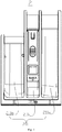
Fig. 1 is a schematic view showing a distributor box according to an embodiment of the present invention; -
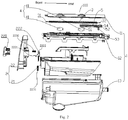
Fig. 2 is an exploded view showing a detergent box for a washing machine according to an embodiment of the present invention; -
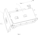
Fig. 3 is a schematic view showing a distributor box in a closed position shown inFig. 2 ; -
Fig. 4 is a partially schematic view showing a detergent box assembly for a washing machine shown inFig. 3 , in which a first cover part is not shown; -
Fig. 5 is a top view showing a detergent box assembly for a washing machine shown inFig. 4 ; -
Fig. 6 is a schematic view showing a distributor box in an open position shown inFig. 2 ; -
Fig. 7 is a partially schematic view showing a detergent box assembly for a washing machine shown inFig. 6 , in which a first cover part is not shown; -
Fig. 8 is a top view showing a detergent box assembly for a washing machine shown inFig. 7 . -
- 100: detergent box assembly;
- 1: detergent box; 11: first cover part; 12: second cover part; 13: base seat;
- 2: distributor box; 21: main body of distributor box; 211: receiving chamber;
211a: first sub receiving chamber; 211b: secondsub receiving chamber 211b; 211c: third sub receiving chamber;- 22: front plate; 221: key-press; 222: lock catch;
- 2221: first guiding surface; 2222: second guiding surface;
- 2231: first compression spring; 2232: second compression spring;
- 3: tension spring; 31: first end; 32: second end;
- 4: gear assembly; 41: damping gear;
- 5: rack; 51: free end; 52: snap-fit end; 53: leg; 54: position limiting part.
- Reference will be made in detail to embodiments of the present disclosure. Embodiments of the present disclosure will be shown in drawings, in which the same or similar elements and the elements having same or similar functions are denoted by like reference numerals throughout the descriptions. The embodiments described herein according to drawings are explanatory and illustrative, not construed to limit the present disclosure.
- The following description provides a plurality of embodiments or examples configured to achieve different structures of the present disclosure. In order to simplify the publishment of the present disclosure, components and dispositions of the particular embodiment are described in the following, which are only explanatory and not construed to limit the present disclosure. In addition, the present disclosure may repeat the reference number and/or letter in different embodiments for the purpose of simplicity and clarity, and the repeat does not indicate the relationship of the plurality of embodiments and/or dispositions. Furthermore, examples of different processes and materials are provided in the present disclosure. However, it would be appreciated by those skilled in the art that other processes and/or materials may be also applied.
- A
detergent box assembly 100 for a washing machine according to embodiments of a first aspect of the present invention will be described in the following with reference toFigs. 1 to 8 . The washing machine may be a front loading washing machine or a top loading washing machine. In following descriptions of the present invention, illustrations are performed by taking the roller washing machine as an example. - As shown in
Fig. 2 , thedetergent box assembly 100 for the washing machine according to the embodiments of the first aspect of the present invention includes adetergent box 1, adistributor box 2 and a driving subassembly. - As shown in
Figs. 1 and2 , thedistributor box 2 has afront plate 22, a rear plate (not shown) and a receivingchamber 211 provided therebetween, and the receivingchamber 211 is configured to store a laundry treat agent. For example, in an embodiment of the present invention inFig. 2 , thedistributor box 2 includes amain body 21 of the distributor box, thefront plate 22 and the rear plate. Thefront plate 22 is fixed at a front end of themain body 21 of the distributor box, and the rear plate is fixed at a rear end of themain body 21 of the distributor box. The receivingchamber 211 whose top end is open is provided in thedistributor box 2 and is used to store the laundry treat. Herein, the laundry treat agent may include scrubbing solution and washing powder, and it should be noted that the scrubbing solution should be understood widely and include all liquid solvent for washing clothes, such as laundry detergent and softener, and also, the washing powder should be understood widely and include all solid powder for washing clothes, such as the washing powder and the bleaching powder. - As shown in
Fig. 1 , the receivingchamber 211 may include a plurality of sub receiving chambers separated from each other and configured to receive different laundry treat agents, and each sub receiving chamber may have a rear end communicating with a scrubbing space in the washing machine. For example, in an embodiment inFig. 1 , the receivingchamber 211 includes three sub receiving chambers extending in a front and rear direction respectively and separated from each other in a right and left direction, i.e., a first sub receiving chamber 211a, a secondsub receiving chamber 211b and a thirdsub receiving chamber 211c. The first sub receiving chamber 211a is a prewashing bin adapted to store the laundry detergent or the washing power, the secondsub receiving chamber 211b is a main washing bin adapted to store the laundry detergent or the washing power, and the thirdsub receiving chamber 211c is adapted to store the softener. It may be understood that, the number and arrangement of the sub receiving chambers may be modified adaptively according to actual requirements, so as to better satisfy the actual requirements. - The
distributor box 2 is movably disposed within thedetergent box 1, i.e., thedistributor box 2 is movable with respect to thedetergent box 1 and thedistributor box 2 is disposed within thedetergent box 1 in at least a moment. Specifically, thedistributor box 2 is adapted to move between an open position and a closed position, i.e., thedistributor box 2 has an open state and a closed state. When thedistributor box 2 moves to the open position (as shown inFig. 6 ), at least a portion of thedistributor box 2 extends out of a front surface of thedetergent box 1, and thus the laundry treat agent can be put into the receivingchamber 211 in thedistributor box 2 at this time. When thedistributor box 2 moves to the closed position (as shown inFig. 3 ), preferably, a front surface of thefront plate 22 of thedistributor box 2 is substantially in flush with the front surface of thedetergent box 1, so as to ensure that the washing machine has a neat and beautiful appearance. - Regardless of an automatically inputting washing machine or a non-automatically inputting washing machine, a user needs to open the
distributor box 2 to put the laundry treat agent into the receivingchamber 211. In particular, for the non-automatically inputting washing machine, the user needs to open thedistributor box 2 each time when washing clothes. If the user needs to draw thedistributor box 2 manually so as to open and close thedistributor box 2 each time, labour intensity of the user will be increased naturally and positivity of the user to use the washing machine will be decreased. - Therefore, in order to open and close the
distributor box 2 easily and conveniently, thedetergent box assembly 100 according to embodiments of the present invention further includes a driving subassembly and a key-press 221. Every time when the user needs to put the laundry treat agent, it only needs to press the key-press 221, and thus thedistributor box 2 can be ejected out automatically or semi-automatically under a driving function of the driving subassembly, so that the user can open thedistributor box 2 easily. Thus, the labour intensity of the user is decreased naturally and the positivity of the user to use the washing machine is improved. - Specifically, the driving subassembly may be disposed in at least one of the
detergent box 1 and thedistributor box 2. That is, the driving subassembly may be disposed in thedistributor box 2, or the driving subassembly may also be disposed in thedetergent box 1, or a portion of the driving subassembly may be disposed in thedistributor box 2 and rest of the driving subassembly may be disposed in thedetergent box 1. A key-press 221 is provided in thefront plate 22, and the driving subassembly is configured to drive thedistributor box 2 to move from the closed position to the open position when the key-press 221 is pressed. That is, after the key-press 221 is pressed, thedistributor box 2 may be ejected forwards out of thedetergent box 1 automatically so as to be opened, so that the receivingchamber 211 is present to the user, which facilitates putting the laundry treat agent into the receivingchamber 211 by the user, without the manual drawing, and improves the usage comfort of the washing machine. Herein, a configuration of the driving subassembly is not limited to one kind of configuration, and the configuration of the driving assembly may be selected by those skilled in the related art according to the actual requirements. In following, detailed descriptions are made regarding to the driving subassembly having one specific configuration. The driving subassembly in the following ensures that thedistributor box 2 can be ejected out stably and reliably, thus improving a working life of thedetergent box assembly 100 effectively. - With the
detergent box assembly 100 for the washing machine according to embodiments of the present invention, regardless of the automatically inputting washing machine or the non-automatically inputting washing machine, by using a mechanical control in which the driving subassembly is fitted with the key-press 211, thedistributor box 2 can be ejected out automatically or semi-automatically without the manual drawing by the user, thus improving the usage comfort. Furthermore, the mechanical control reduces a cost effectively. - In an embodiment of the present invention, as shown in
Fig. 2 , thedetergent box 1 may include abase seat 13 and an upper cover subassembly (for example, including afirst cover part 11 and a second upper body as shown in 2, in which thefirst cover part 11 is in an upper position and thesecond cover part 12 is in a lower position). The upper cover subassembly is mounted at a top of thebase seat 13 so as to define a space for receiving thedistributor box 2 together with thebase seat 13. The driving subassembly includes agear assembly 4, arack 5 and a tension spring 3. Thegear assembly 4 is disposed on the upper cover subassembly, and therack 5 is provided on the upper cover subassembly and adapted to be engaged with thegear assembly 4, i.e., therack 5 can drive a gear of thegear assembly 4 to rotate during a movement of therack 5, or the gear of thegear assembly 4 can drive therack 5 to move during a rotation of the gear of thegear assembly 4. - In an embodiment of the present invention, as shown in
Fig. 2 , thedetergent box assembly 100 further includes alock catch 222, and thelock catch 222 is associated with the key-press 221 and provided in thedistributor box 2. Thelock catch 222 is configured to be lockably engaged by the washing machine such that when the key-press 221 is pressed, thelock catch 222 is unlocked and disengaged by the washing machine. That is, in general, thelock catch 222 may be connected with the washing machine in a lock catch manner so as to be tightly locked thereby, and after the key-press 221 is pressed, thelock catch 222 may be unlocked by the washing machine so as to be separated therefrom. After thelock catch 222 is unlocked and disengaged by the washing machine, therack 5 is driven by the tension spring 3 to enable move thedistributor box 2 to be moved from the closed position to the open position. - In preferred embodiments of the present invention, the
gear assembly 4 may include a dampinggear 41 which may be configured as a gear having a damping function, preferably as a fluid damping gear. In an engaged movement of the dampinggear 4 and therack 5, a damping force may be generated so as to slow down the movement strength and speed of therack 5. - The
rack 5 has a free end 51 (for example, a front end of therack 5 as shown inFig. 2 , i.e., the front end of therack 5 may be configured as the free end) adjacent to thefront plate 22 of thedistributor box 2 and a snap-fit end 52 (for example, a rear end of therack 5 as shown inFig. 2 , i.e., the rear end of therack 5 may be configured as the snap-fit end) away from thefront plate 22 of thedistributor box 2 and opposite to thefree end 51 along a length direction thereof. The snap-fit end 52 of therack 5 is configured to be engageable with the rear plate of thedistributor box 2, i.e., the snap-fit end 52 may be coupled with the rear plate of thedistributor box 2 in a snap-fit manner. Briefly, therack 5 is mounted in thedetergent box 1 and the rear end of therack 5 penetrates through thesecond cover part 12 of thedetergent box 1 and is engageable with the rear plate of thedistributor box 2. - It should be noted that, the snap-fit manner is well known by those skilled in the related art, which thus is omitted herein and is illustrated with a specific example. Optionally, the snap-
fit end 52 of therack 5 is formed with a downwardly-extendingleg 53 engageable with the rear plate of thedistributor box 2, a snap-fit hole is provided in the rear plate of thedistributor box 2, and theleg 53 penetrates through the upper cover subassembly of the detergent box 1 (for example penetrating through thesecond cover part 12 downwards as shown inFig. 2 ) and is inserted within the snap-fit hole, so that therack 5 is engageable with thedistributor box 2. - The tension spring 3 is disposed in the length direction of the
rack 5, i.e., a tension direction of the tension spring 3 is the same with that of the length of therack 5. The tension spring 3 has afirst end 31 and asecond end 32 opposite to thefirst end 31. The first end 31 (such as a front end of the tension spring 3 as shown inFig. 2 ) is adjacent to thefront plate 22 of thedistributor box 2 and mounted on the upper cover subassembly (such as the first upper cover part 11) of thedetergent box 1 adjacent to thefront plate 22 of thedistributor box 2 and the second end 32 (such as a rear end of the tension spring 3 as shown inFig. 2 ) is coupled to therack 5 and adjacent to the snap-fit end 52 of therack 5. Optionally, thesecond end 32 of the tension spring 3 may be fixed to the snap-fit end 52 of therack 5. Briefly, the tension spring 3 is mounted in thedetergent box 1, the front end of the tension spring 3 is substantially fixed with the front end of thedetergent box 1, and the rear end of the tension spring 3 is substantially fixed with the rear end of therack 5 on thedistributor box 2. - It should be noted that, coupling is well known by those skilled in the related art, which thus is omitted herein and is illustrated with a specific example. For example, as shown in
Fig. 2 , aposition limiting part 54 extending upwards may be provided at the snap-fit end 52 of therack 5, a rear hook may be provided at thesecond end 32 of the tension spring 3, and the rear hook may be hooked by theposition limiting part 54, so that thesecond end 32 of the tension spring 3 can be fixed with the snap-fit end 52 of therack 5. Thus, the tension spring 3 can be assembled with therack 5 conveniently and rapidly. - As shown in
Fig. 2 , the upper cover subassembly of thedetergent box 1 includes thefirst cover part 11 and thesecond cover part 12 assembled with each other. Thesecond cover part 12 is provided with a mounting slot, which extends in the front and rear direction and penetrates through thesecond cover part 12 in the upper and lower direction. Therack 5 is mounted within the mounting slot of thesecond cover part 12 and freely movable in the front and rear direction. Thus, by providing the mounting slot, it is ensured that therack 5 moves in the front and back direction stably without getting off track. - In this way, when the
distributor box 2 is in the closed position, thedistributor box 2 is received in thedetergent box 1, the front end of thedistributor box 2 is adjacent to the front end of thedetergent box 1, and the rear end of thedistributor box 2 is adjacent to the rear end of thedetergent box 1. Therack 5 is movably installed in thesecond cover part 12 and engageble with thedistributor box 2, and the tension spring 3 is mounted between thefirst cover part 11 and therack 5. The front end of the tension spring 3 is fixed to a front end of thefirst cover part 11, and the rear end of the tension spring 3 is fixed to the rear end of therack 5, so that the tension spring 3 is in a tension state. - When a force acted on the tension spring 3 is removed, the tension spring 3 tends to contract and recover. At this time, the front end of the tension spring 3 is fixed to the
first cover part 11 and does not move, and the rear end of the tension spring 3 drives the rear end of therack 5 to move forwards. Therack 5 drives thedistributor box 2 connected with therack 5 to move forwards at the same time, so that thedistributor box 2 can be ejected out. When thedistributor box 2 moves to the open position, the tension spring 3 may just contract to an original length state. - Thus, by providing the tension spring 3, the
distributor box 2 moves from the closed position to the open position under a spring force, without the manual drawing, thus improving the usage comfort. Preferably, the tension spring 3 may be configured as a cylindrical tension spring. In addition, configuration and operating principle of the tension spring 3 are well known by those skilled in the related art, which are omitted herein. - In an embodiment of the present invention, the
gear assembly 4 includes at least one dampinggear 41 and the dampinggear 41 may be mounted at thefirst cover part 12 and disposed adjacent to a side edge of the mounting slot. Thus, when therack 5 and thedistributor box 2 are ejected out together under a force of the tension spring 3, since the dampinggear 41 is disposed at thefirst cover part 12 which is stationary, the engaged movement is generated between therack 5 and the dampinggear 41. That is, therack 5 drives the dampinggear 41 to rotate when moving forwards with respect to thegear assembly 4, and thus the dampinggear 41 plays a damping role, which slows down a ejecting strength and the speed of therack 5 and thedistributor box 2, and results in that thedistributor box 2 can be ejected out stably. - Further preferably, as shown in
Fig. 2 , thegear assembly 4 may include a plurality of dampinggears 41 and the plurality of dampinggears 41 is disposed adjacent to a same side of the mounting slot, i.e., the plurality of dampinggears 41 is disposed adjacent to the same side of the mounting slot in a width direction of the mounting slot, and at this time, an engaging tooth may be only provided at one side of therack 5 in a width direction of therack 5 so as to be engaged with the plurality of dampinggears 41 respectively. Thus, by providing the plurality of dampinggears 41, a more effective damping function can be obtained, so that thedistributor box 2 can be ejected out forwards more stably. In addition, since the plurality of dampinggears 41 is mounted at the same side of the mounting slot, it is convenient to assemble, a high space utilization is provided and a manufacturing difficulty of therack 5 is reduced. - Preferably, the damping
gear 41 has thereof a horizontally-arranged rotation axis, so that the dampinggear 41 can roll in a vertical plane. In this way, the engaging tooth of therack 5 may be formed by depressing an upper end surface of therack 5 down, so that it is convenient to manufacture, and thedetergent box assembly 100 has a more compact configuration and a more reliable operating effect. - With the
detergent box assembly 100 for the washing machine according to embodiments of the present invention, via the fitting among the tension spring 3, thegear assembly 4 and therack 5, a simple configuration is provided and the cost is saved greatly. Furthermore, the ejecting strength and ejecting speed of thedistributor box 2 are controlled effectively, so that thedistributor box 2 can be ejected out freely and stably, and thus the operating reliability of thedistributor box 2 and the operating life of thedetergent box assembly 100 can be improved. - In some embodiments of the present disclosure, as shown in
Figs. 2 and3 , the key-press 221 is preferably provided in the center of thefront plate 22, so that it is convenient for the user to operate. Optionally, thelock catch 222 may be fitted with the upper cover subassembly of thedetergent box 1 in the lock catch manner. In a preferred embodiment of the present invention, thelock catch 222 may be fitted with thesecond cover part 12 of thedetergent box 1 in the lock catch manner. For example, a lock hole is provided in thesecond cover part 12, and thelock catch 222 penetrates through the front end of thedistributor box 2 and movable therein in an up and down direction. Specifically, afirst compression spring 2231 is provided at a lower end of thelock catch 222 and asecond compression spring 2232 is provided between the key-press 221 and thelock catch 222. - In general, the
first compression spring 2231 and thesecond compression spring 2232 are in an original length state, and thefirst compression spring 2231 raises thelock catch 222 to be inserted into the lock hole of thesecond cover part 12, so as to be lockably engaged by the washing machine. When the key-press 221 is pressed backwards, the key-press 221 pushes thesecond compression spring 2232 to be compressed backwards and thesecond compression spring 2232 pushes thelock catch 222 to move downwards to be out of the lock hole, so as to be separated from the washing machine, in which thelock catch 222 pushes thefirst compression spring 2231 to be compressed downwards at the same time when thelock catch 222 moves downwards. - When a force acted on the key-
press 221 is removed, thefirst compression spring 2231 is ejected up under a spring force thereof to push thelock catch 222 to move upwards. At the same time, thelock catch 222 pushes thesecond compression spring 2232 forwards to return to its original length, and thesecond compression spring 2232 pushes the key-press 221 to move forwards to return to its original position. - Thus, when the
distributor box 2 is in the closed position, thelock catch 222 is lockably engaged in the washing machine, and the tension spring 3 is in the tension state (as shown inFigs. 4 and 5 ). When the key-press 221 in the front surface of thedistributor box 2 is pressed, thelock catch 222 breaks away from the lock hole in the washing machine, and the tension spring 3 contracts to a compression state under its own spring force (as shown inFigs. 7 and8 ), so as to drive thedistributor box 2 to be ejected out forwards to the open position, and at this time, the user can put the laundry treat agent into the receivingchamber 211 ejected out. Certainly, the user may release the key-press 211 after pressing the key-press 221 down, and then thelock catch 222 can be ejected up automatically and the key-press 221 can return forwards to its original position at the same time. - After the user has put the laundry treat agent (such as the washing powder, the laundry detergent and the softener) into the receiving
chamber 211 of thedistributor box 2, the user may push thedistributor box 2 backwards until thelock catch 222 touches thesecond cover part 12, and then, when thedistributor box 2 is further pushed backwards, thesecond cover part 12 pushes thelock catch 222 to move downwards with respect to thesecond cover part 12 and to compress thefirst compression spring 2231. When thelock catch 222 moves backwards to a position in which thelock catch 222 is opposed to the lock hole, a downward pressure is no longer acted on thelock catch 222, so that thelock catch 222 can be ejected up automatically under the spring force of thefirst compression spring 2231 so as to be lockably engaged in the washing machine, so that thedistributor box 2 can be remained in the closed position. - It should be noted that, the
lock catch 222 may include afirst guiding surface 2221 and asecond guiding surface 2222. Thefirst guiding surface 2221 is provided at a front end of thelock catch 222 and extends forwards and downwards, and thesecond guiding surface 2222 is provided at an upper end of thelock catch 222 and extends backwards and downwards. By providing thefirst guiding surface 2221, it is ensured that thelock catch 222 can move downwards when the key-press 221 is pushed backwards. By providing thesecond guiding surface 2222, thesecond cover part 12 can push thelock catch 222 to move downwards when thedistributor box 2 is pushed backwards. Certainly, the present invention is not limited to this. - Briefly, after the key-
press 221 is pressed, thedistributor box 2 is driven by the tension spring 3 to move forwards to the open position from the closed position. In this way, by providing the key-press 221 and the tension spring 3, thedistributor box 2 can automatically move to the open position from the closed position only by pressing the key-press 221, without the manual drawing, thus resulting in a better usage comfort. Furthermore, by providing the key-press 221, overall aesthetics and neatness of thedetergent box assembly 100 are improved. - Certainly, a configuration and a disposition position of the key-
press 221 are not limited to this, and a technical solution of locking and catching thedistributor box 2 in the closed position and releasing thedistributor box 2 is not limited to the fitting of the key-press 221 and thelock catch 222 as shown inFig. 2 . For example, when thedistributor box 2 moves to the closed position, thedistributor box 2 may be locked by a hasp configuration, and then the user may unhasp the hasp configuration by himself, so that thedistributor box 2 can be ejected out forwards. Embodiments thereof are well known by those skilled in the related art, which are omitted herein. - Specifically, the
detergent box assembly 100 for the washing machine according to above embodiments of the present invention may be used in the washing machine, and thus a washing machine according to embodiments of a second aspect of the present invention may include thedetergent box assembly 100 according to the above embodiments of the present invention. In some embodiments, the washing machine further includes a machine housing assembly and the machine housing assembly has thedetergent box 1. In some embodiments, the machine housing assembly includes a machine body and thedetergent box 1, and thedetergent box 1 is fixedly mounted in the machine body. In addition, other features of thedetergent box assembly 100 have been described in detail above, and are omitted herein. - With the washing machine according to embodiments of the present invention, by providing the driving subassembly and the key-
press 221, thedistributor box 2 can be ejected out smoothly without the manual drawing, thus improving the usage comfort of the washing machine. In addition, via the fitting among the tension spring 3, thegear assembly 4 and therack 5, the ejecting strength and ejecting speed of thedistributor box 2 are controlled effectively, so that thedistributor box 2 can be ejected out freely and stably, and thus the operating reliability of thedistributor box 2 and the operating life of thedetergent box assembly 100 can be improved. Moreover, other configurations and operations of the washing machine according to embodiments of the present invention are known by those skilled in the related art and omitted herein. - In the specification, unless specified or limited otherwise, relative terms such as "central", "longitudinal", "lateral", "length", "width", "thickness", "up", "down", "front", "rear", "right", "left", "vertical", "horizontal", "top", "bottom", "inner", "outer", as well as derivative thereof (e.g., "horizontally", "downwardly", "upwardly", etc.) should be construed to refer to the orientation as then described or as shown in the drawings under discussion. These relative terms are for convenience of description and do not require that the present disclosure be constructed or operated in a particular orientation.
- In the description of the present disclosure, unless specified or limited otherwise, it should be noted that, terms "mounted", "connected" and "coupled" may be understood broadly, such as permanent connection or detachable connection, electronic connection or mechanical connection, direct connection or indirect connection via intermediary, inner communication or interreaction between two elements. These having ordinary skills in the art should understand the specific meanings in the present disclosure according to specific situations.
- In the description of the present disclosure, a structure in which a first feature is "on" a second feature may include an embodiment in which the first feature directly contacts the second feature, and may also include an embodiment in which an additional feature is formed between the first feature and the second feature so that the first feature does not directly contact the second feature, unless otherwise specified. Furthermore, a first feature "on", "above", or "on top of' a second feature may include an embodiment in which the first feature is right "on", "above", or "on top of' the second feature, and may also include an embodiment in which the first feature is not right "on", "above", or "on top of' the second feature, or just means that the first feature has a sea level elevation larger than the sea level elevation of the second feature. While first feature "beneath", "below", or "on bottom of' a second feature may include an embodiment in which the first feature is right "beneath", "below", or "on bottom of' the second feature, and may also include an embodiment in which the first feature is not right "beneath", "below", or "on bottom of' the second feature, or just means that the first feature has a sea level elevation smaller than the sea level elevation of the second feature.
- Reference throughout this specification to "an embodiment", "some embodiments", "one embodiment", "another example", "an example", "a specific example", or "some examples", means that a particular feature, structure, material, or characteristic described in connection with the embodiment or example is included in at least one embodiment or example of the present invention. Thus, the appearances of the phrases such as "in some embodiments", "in one embodiment", "in an embodiment", "in another example", "in an example", "in a specific example", or "in some examples", in various places throughout this specification are not necessarily referring to the same embodiment or example of the present invention. Furthermore, the particular features, structures, materials, or characteristics may be combined in any suitable manner in one or more embodiments or examples.
Claims (8)
- A detergent box assembly (100) for a washing machine, comprising:a detergent box (1) provided with an upper cover subassembly;a distributor box (2) having a front plate (22), a rear plate and a receiving chamber (211) provided therebetween, said receiving chamber (211) configured to store a laundry treat agent, the distributor box (2) being movably disposed within the detergent box (1) and adapted to move between an open position and a closed position, a key-press (221) being provided in the front plate (22); a lock catch (222) associated with the key-press (221) and provided at the distributor box (2); anda driving subassembly configured to drive the distributor box (2) to move from the closed position to the open position when the key-press (221) is pressed; characterized in that the driving subassembly comprises:a gear assembly (4);a rack (5); anda tension spring (3); wherein the gear assembly (4) is disposed on the upper cover subassembly of the detergent box (1);the rack (5) is provided on the upper cover subassembly of the detergent box (1) and adapted to be engaged with the gear assembly (4), the rack (5) having a free end (51) adjacent to the front plate (22) of the distributor box (2) and a snap-fit end (52) away from the front plate (22) of the distributor box (2) and opposite to the free end (51) along a length direction thereof, the snap-fit end (52) of the rack (5) being configured to be engageable with the rear plate of the distributor box (2) and formed with a downwardly-extending leg (53) engageable with the rear plate of the distributor box (2); andthe tension spring (3) is disposed along the length direction of the rack (5) and has a first end (31) and a second end (32) opposite to the first end (31), the first end (31) being adjacent to the front plate (22) of the distributor box (2) and mounted on the upper cover subassembly of the detergent box (1), the second end (32) being coupled to the rack (5) and adjacent to the snap-fit end (52) of the rack (5); wherein the lock catch (222) is configured to be lockably engaged by the washing machine such that when the key-press (221) is pressed, the lock catch (222) is unlocked and disengaged by the washing machine, the rack (5) is driven by the tension spring (3) to enable the distributor box (2) to be moved from the closed position to the open position, andthe upper cover subassembly of the detergent box (1) comprises a first cover part (11) and a second cover part (12) assembled with each other, the second cover part (12) is provided with a mounting slot and the rack (5) is mounted within the mounting slot of the second cover part (12).
- The detergent box assembly (100) for the washing machine according to claim 1, wherein the second end (32) of the tension spring (3) is fixed to the snap-fit end (52) of the rack (5).
- The detergent box assembly (100) for the washing machine according to claim 1, wherein the gear assembly (4) comprises at least one damping gear (41) disposed adjacent to a side edge of the mounting slot.
- The detergent box assembly (100) for the washing machine according to claim 3, wherein the gear assembly (4) comprises a plurality of damping gears (41) disposed adjacent to a same side of the mounting slot.
- The detergent box assembly (100) for the washing machine according to claim 3 or 4, wherein the damping gear (41) defines thereof a horizontally-arranged rotation axis.
- The detergent box assembly (100) for the washing machine according to claim 1, further comprising a lock catch (222) associated with the key-press (221) and provided at the distributor box (2), the lock catch (222) being lockably engaged on the upper cover subassembly of the detergent box (1) so as to keep the lock catch (222) located at a lock-catch manner on the washing machine.
- The detergent box assembly (100) for the washing machine according to claim 6, wherein the upper cover assembly of the detergent box (1) comprises a first cover part (11) and a second cover part (12) assembled with each other, the lock catch (222) is lockably engaged on the second cover part (12) of the detergent box (1) to keep the lock catch (222) in the lock-catch manner.
- A washing machine, comprising the detergent box assembly (100) according to any one of claims 1-7, wherein the detergent box (1) is included in a machine housing assembly of the washing machine.
Applications Claiming Priority (4)
| Application Number | Priority Date | Filing Date | Title |
|---|---|---|---|
| CN201510112716.5A CN106032628B (en) | 2015-03-13 | 2015-03-13 | Box component for washing agent and its washing machine for washing machine |
| CN201520145097.5U CN204608429U (en) | 2015-03-13 | 2015-03-13 | For box component for washing agent and the washing machine thereof of washing machine |
| CN201510494878.XA CN105063966B (en) | 2015-08-12 | 2015-08-12 | Box component for washing agent and washing machine for washing machine |
| CN201520607469.1U CN205012054U (en) | 2015-08-12 | 2015-08-12 | A detergent cartridge assembly and washing machine for washing machine |
Publications (2)
| Publication Number | Publication Date |
|---|---|
| EP3067458A1 EP3067458A1 (en) | 2016-09-14 |
| EP3067458B1 true EP3067458B1 (en) | 2018-09-05 |
Family
ID=55229558
Family Applications (1)
| Application Number | Title | Priority Date | Filing Date |
|---|---|---|---|
| EP16152070.5A Active EP3067458B1 (en) | 2015-03-13 | 2016-01-20 | Detergent box assembly for washing machine and washing machine |
Country Status (1)
| Country | Link |
|---|---|
| EP (1) | EP3067458B1 (en) |
Cited By (2)
| Publication number | Priority date | Publication date | Assignee | Title |
|---|---|---|---|---|
| US20250075404A1 (en) * | 2023-08-28 | 2025-03-06 | Whirlpool Corporation | Fluid treatment module for an appliance that includes a microfiber filter access mechanism |
| US12630963B2 (en) * | 2023-08-28 | 2026-05-19 | Whirlpool Corporation | Fluid treatment module for an appliance that includes a microfiber filter access mechanism |
Families Citing this family (4)
| Publication number | Priority date | Publication date | Assignee | Title |
|---|---|---|---|---|
| EP3617381B1 (en) * | 2018-08-30 | 2021-10-06 | Electrolux Appliances Aktiebolag | Laundry appliance having a drawer provided with improved top cover |
| CN111321558B (en) * | 2020-02-28 | 2023-06-13 | 青岛胶南海尔洗衣机有限公司 | Put in box and washing machine |
| CN114451699A (en) * | 2021-12-16 | 2022-05-10 | 杭州神林电子有限公司 | Push away bullet formula stock solution box |
| CN116926891A (en) * | 2022-03-29 | 2023-10-24 | 无锡小天鹅电器有限公司 | Throwing device for clothes treatment equipment and clothes treatment equipment with same |
Family Cites Families (6)
| Publication number | Priority date | Publication date | Assignee | Title |
|---|---|---|---|---|
| DE4021966A1 (en) * | 1990-07-10 | 1992-01-16 | Bosch Siemens Hausgeraete | WASHING MACHINE WITH A DETERGENT TRAY |
| ITTO20020813A1 (en) * | 2002-09-19 | 2004-03-20 | Itw Ind Components Srl | DEVICE FOR THE AUTOMATIC EXTRACTION OF A DRAWER, IN PARTICULAR A DRAWER OF A HOUSEHOLD APPLIANCE SUCH AS A WASHING MACHINE, AND HOUSEHOLD APPLIANCE USING THE SAME. |
| SI21804A (en) * | 2004-05-06 | 2005-12-31 | Gorenje D.D. | Dosing container for washing agents in washing machine |
| US8317236B2 (en) * | 2008-04-16 | 2012-11-27 | Electrolux Home Products, Inc. | Appliance drawer and latch mechanism therefor |
| US8348361B2 (en) * | 2008-06-30 | 2013-01-08 | Electrolux Home Products, Inc. | Additive dispenser drawer assembly |
| CN203729113U (en) * | 2014-01-09 | 2014-07-23 | Tcl家用电器(合肥)有限公司 | Washing machine drawer box and washing machine |
-
2016
- 2016-01-20 EP EP16152070.5A patent/EP3067458B1/en active Active
Cited By (2)
| Publication number | Priority date | Publication date | Assignee | Title |
|---|---|---|---|---|
| US20250075404A1 (en) * | 2023-08-28 | 2025-03-06 | Whirlpool Corporation | Fluid treatment module for an appliance that includes a microfiber filter access mechanism |
| US12630963B2 (en) * | 2023-08-28 | 2026-05-19 | Whirlpool Corporation | Fluid treatment module for an appliance that includes a microfiber filter access mechanism |
Also Published As
| Publication number | Publication date |
|---|---|
| EP3067458A1 (en) | 2016-09-14 |
Similar Documents
| Publication | Publication Date | Title |
|---|---|---|
| EP2740830B1 (en) | Detergent case apparatus for washing machine | |
| EP2738298B1 (en) | Detergent drawer | |
| US10876331B2 (en) | Appliance door lock | |
| CN105063966B (en) | Box component for washing agent and washing machine for washing machine | |
| CN103741432B (en) | drawer box of washing machine and washing machine | |
| EP3067458A1 (en) | Detergent box assembly for washing machine and washing machine | |
| KR20170118119A (en) | Sliding-pivoting devices for furniture or appliances shelves, furniture and appliances | |
| CN204608424U (en) | For washing machine box component for washing agent and there is its washing machine | |
| CN111820726B (en) | Water tank push-out structure of cooking device | |
| CN110604530B (en) | Detergent additive for dishwasher and dishwasher | |
| CN113229707B (en) | Cooking water tank and steaming cooking equipment with same | |
| CN107366133B (en) | Washing machine's detergent box subassembly and washing machine thereof | |
| EP3904584B1 (en) | Washing machine including drawer | |
| CN204608425U (en) | For washing machine box component for washing agent and there is its washing machine | |
| EP3269870B1 (en) | Detergent container assembly for washing machine, and washing machine having same | |
| CN101991396B (en) | Dishwasher, in particular domestic dishwasher | |
| CN109708416B (en) | Drawer component | |
| CN115944253B (en) | A door mechanism and a household appliance | |
| CN110273603B (en) | Oven | |
| KR20120133542A (en) | a tray unlocking apparatus | |
| CN108004729A (en) | A kind of door of washing machine lock construction and roller washing machine | |
| CN211818747U (en) | Door lock structure for electric appliance and cleaning machine with door lock structure | |
| CN108209227B (en) | Combined kitchen appliances | |
| KR20070036468A (en) | Drum washing machine | |
| CN217872263U (en) | Door lock structure for household appliance and household appliance |
Legal Events
| Date | Code | Title | Description |
|---|---|---|---|
| PUAI | Public reference made under article 153(3) epc to a published international application that has entered the european phase |
Free format text: ORIGINAL CODE: 0009012 |
|
| AK | Designated contracting states |
Kind code of ref document: A1 Designated state(s): AL AT BE BG CH CY CZ DE DK EE ES FI FR GB GR HR HU IE IS IT LI LT LU LV MC MK MT NL NO PL PT RO RS SE SI SK SM TR |
|
| AX | Request for extension of the european patent |
Extension state: BA ME |
|
| STAA | Information on the status of an ep patent application or granted ep patent |
Free format text: STATUS: REQUEST FOR EXAMINATION WAS MADE |
|
| 17P | Request for examination filed |
Effective date: 20170124 |
|
| RBV | Designated contracting states (corrected) |
Designated state(s): AL AT BE BG CH CY CZ DE DK EE ES FI FR GB GR HR HU IE IS IT LI LT LU LV MC MK MT NL NO PL PT RO RS SE SI SK SM TR |
|
| STAA | Information on the status of an ep patent application or granted ep patent |
Free format text: STATUS: EXAMINATION IS IN PROGRESS |
|
| 17Q | First examination report despatched |
Effective date: 20170623 |
|
| GRAP | Despatch of communication of intention to grant a patent |
Free format text: ORIGINAL CODE: EPIDOSNIGR1 |
|
| STAA | Information on the status of an ep patent application or granted ep patent |
Free format text: STATUS: GRANT OF PATENT IS INTENDED |
|
| INTG | Intention to grant announced |
Effective date: 20180316 |
|
| GRAS | Grant fee paid |
Free format text: ORIGINAL CODE: EPIDOSNIGR3 |
|
| GRAA | (expected) grant |
Free format text: ORIGINAL CODE: 0009210 |
|
| STAA | Information on the status of an ep patent application or granted ep patent |
Free format text: STATUS: THE PATENT HAS BEEN GRANTED |
|
| AK | Designated contracting states |
Kind code of ref document: B1 Designated state(s): AL AT BE BG CH CY CZ DE DK EE ES FI FR GB GR HR HU IE IS IT LI LT LU LV MC MK MT NL NO PL PT RO RS SE SI SK SM TR |
|
| REG | Reference to a national code |
Ref country code: GB Ref legal event code: FG4D |
|
| REG | Reference to a national code |
Ref country code: CH Ref legal event code: EP |
|
| REG | Reference to a national code |
Ref country code: AT Ref legal event code: REF Ref document number: 1037933 Country of ref document: AT Kind code of ref document: T Effective date: 20180915 |
|
| REG | Reference to a national code |
Ref country code: IE Ref legal event code: FG4D |
|
| REG | Reference to a national code |
Ref country code: DE Ref legal event code: R096 Ref document number: 602016005228 Country of ref document: DE |
|
| REG | Reference to a national code |
Ref country code: NL Ref legal event code: MP Effective date: 20180905 |
|
| REG | Reference to a national code |
Ref country code: LT Ref legal event code: MG4D |
|
| PG25 | Lapsed in a contracting state [announced via postgrant information from national office to epo] |
Ref country code: FI Free format text: LAPSE BECAUSE OF FAILURE TO SUBMIT A TRANSLATION OF THE DESCRIPTION OR TO PAY THE FEE WITHIN THE PRESCRIBED TIME-LIMIT Effective date: 20180905 Ref country code: BG Free format text: LAPSE BECAUSE OF FAILURE TO SUBMIT A TRANSLATION OF THE DESCRIPTION OR TO PAY THE FEE WITHIN THE PRESCRIBED TIME-LIMIT Effective date: 20181205 Ref country code: SE Free format text: LAPSE BECAUSE OF FAILURE TO SUBMIT A TRANSLATION OF THE DESCRIPTION OR TO PAY THE FEE WITHIN THE PRESCRIBED TIME-LIMIT Effective date: 20180905 Ref country code: NO Free format text: LAPSE BECAUSE OF FAILURE TO SUBMIT A TRANSLATION OF THE DESCRIPTION OR TO PAY THE FEE WITHIN THE PRESCRIBED TIME-LIMIT Effective date: 20181205 Ref country code: LT Free format text: LAPSE BECAUSE OF FAILURE TO SUBMIT A TRANSLATION OF THE DESCRIPTION OR TO PAY THE FEE WITHIN THE PRESCRIBED TIME-LIMIT Effective date: 20180905 Ref country code: GR Free format text: LAPSE BECAUSE OF FAILURE TO SUBMIT A TRANSLATION OF THE DESCRIPTION OR TO PAY THE FEE WITHIN THE PRESCRIBED TIME-LIMIT Effective date: 20181206 Ref country code: RS Free format text: LAPSE BECAUSE OF FAILURE TO SUBMIT A TRANSLATION OF THE DESCRIPTION OR TO PAY THE FEE WITHIN THE PRESCRIBED TIME-LIMIT Effective date: 20180905 |
|
| REG | Reference to a national code |
Ref country code: AT Ref legal event code: MK05 Ref document number: 1037933 Country of ref document: AT Kind code of ref document: T Effective date: 20180905 |
|
| PG25 | Lapsed in a contracting state [announced via postgrant information from national office to epo] |
Ref country code: LV Free format text: LAPSE BECAUSE OF FAILURE TO SUBMIT A TRANSLATION OF THE DESCRIPTION OR TO PAY THE FEE WITHIN THE PRESCRIBED TIME-LIMIT Effective date: 20180905 Ref country code: AL Free format text: LAPSE BECAUSE OF FAILURE TO SUBMIT A TRANSLATION OF THE DESCRIPTION OR TO PAY THE FEE WITHIN THE PRESCRIBED TIME-LIMIT Effective date: 20180905 Ref country code: HR Free format text: LAPSE BECAUSE OF FAILURE TO SUBMIT A TRANSLATION OF THE DESCRIPTION OR TO PAY THE FEE WITHIN THE PRESCRIBED TIME-LIMIT Effective date: 20180905 |
|
| PG25 | Lapsed in a contracting state [announced via postgrant information from national office to epo] |
Ref country code: ES Free format text: LAPSE BECAUSE OF FAILURE TO SUBMIT A TRANSLATION OF THE DESCRIPTION OR TO PAY THE FEE WITHIN THE PRESCRIBED TIME-LIMIT Effective date: 20180905 Ref country code: IS Free format text: LAPSE BECAUSE OF FAILURE TO SUBMIT A TRANSLATION OF THE DESCRIPTION OR TO PAY THE FEE WITHIN THE PRESCRIBED TIME-LIMIT Effective date: 20190105 Ref country code: IT Free format text: LAPSE BECAUSE OF FAILURE TO SUBMIT A TRANSLATION OF THE DESCRIPTION OR TO PAY THE FEE WITHIN THE PRESCRIBED TIME-LIMIT Effective date: 20180905 Ref country code: PL Free format text: LAPSE BECAUSE OF FAILURE TO SUBMIT A TRANSLATION OF THE DESCRIPTION OR TO PAY THE FEE WITHIN THE PRESCRIBED TIME-LIMIT Effective date: 20180905 Ref country code: CZ Free format text: LAPSE BECAUSE OF FAILURE TO SUBMIT A TRANSLATION OF THE DESCRIPTION OR TO PAY THE FEE WITHIN THE PRESCRIBED TIME-LIMIT Effective date: 20180905 Ref country code: EE Free format text: LAPSE BECAUSE OF FAILURE TO SUBMIT A TRANSLATION OF THE DESCRIPTION OR TO PAY THE FEE WITHIN THE PRESCRIBED TIME-LIMIT Effective date: 20180905 Ref country code: AT Free format text: LAPSE BECAUSE OF FAILURE TO SUBMIT A TRANSLATION OF THE DESCRIPTION OR TO PAY THE FEE WITHIN THE PRESCRIBED TIME-LIMIT Effective date: 20180905 Ref country code: RO Free format text: LAPSE BECAUSE OF FAILURE TO SUBMIT A TRANSLATION OF THE DESCRIPTION OR TO PAY THE FEE WITHIN THE PRESCRIBED TIME-LIMIT Effective date: 20180905 Ref country code: NL Free format text: LAPSE BECAUSE OF FAILURE TO SUBMIT A TRANSLATION OF THE DESCRIPTION OR TO PAY THE FEE WITHIN THE PRESCRIBED TIME-LIMIT Effective date: 20180905 |
|
| PG25 | Lapsed in a contracting state [announced via postgrant information from national office to epo] |
Ref country code: SM Free format text: LAPSE BECAUSE OF FAILURE TO SUBMIT A TRANSLATION OF THE DESCRIPTION OR TO PAY THE FEE WITHIN THE PRESCRIBED TIME-LIMIT Effective date: 20180905 Ref country code: PT Free format text: LAPSE BECAUSE OF FAILURE TO SUBMIT A TRANSLATION OF THE DESCRIPTION OR TO PAY THE FEE WITHIN THE PRESCRIBED TIME-LIMIT Effective date: 20190105 Ref country code: SK Free format text: LAPSE BECAUSE OF FAILURE TO SUBMIT A TRANSLATION OF THE DESCRIPTION OR TO PAY THE FEE WITHIN THE PRESCRIBED TIME-LIMIT Effective date: 20180905 |
|
| REG | Reference to a national code |
Ref country code: DE Ref legal event code: R097 Ref document number: 602016005228 Country of ref document: DE |
|
| PLBE | No opposition filed within time limit |
Free format text: ORIGINAL CODE: 0009261 |
|
| STAA | Information on the status of an ep patent application or granted ep patent |
Free format text: STATUS: NO OPPOSITION FILED WITHIN TIME LIMIT |
|
| PG25 | Lapsed in a contracting state [announced via postgrant information from national office to epo] |
Ref country code: DK Free format text: LAPSE BECAUSE OF FAILURE TO SUBMIT A TRANSLATION OF THE DESCRIPTION OR TO PAY THE FEE WITHIN THE PRESCRIBED TIME-LIMIT Effective date: 20180905 |
|
| 26N | No opposition filed |
Effective date: 20190606 |
|
| PG25 | Lapsed in a contracting state [announced via postgrant information from national office to epo] |
Ref country code: MC Free format text: LAPSE BECAUSE OF FAILURE TO SUBMIT A TRANSLATION OF THE DESCRIPTION OR TO PAY THE FEE WITHIN THE PRESCRIBED TIME-LIMIT Effective date: 20180905 Ref country code: SI Free format text: LAPSE BECAUSE OF FAILURE TO SUBMIT A TRANSLATION OF THE DESCRIPTION OR TO PAY THE FEE WITHIN THE PRESCRIBED TIME-LIMIT Effective date: 20180905 |
|
| REG | Reference to a national code |
Ref country code: CH Ref legal event code: PL |
|
| PG25 | Lapsed in a contracting state [announced via postgrant information from national office to epo] |
Ref country code: LU Free format text: LAPSE BECAUSE OF NON-PAYMENT OF DUE FEES Effective date: 20190120 |
|
| REG | Reference to a national code |
Ref country code: BE Ref legal event code: MM Effective date: 20190131 |
|
| REG | Reference to a national code |
Ref country code: IE Ref legal event code: MM4A |
|
| PG25 | Lapsed in a contracting state [announced via postgrant information from national office to epo] |
Ref country code: FR Free format text: LAPSE BECAUSE OF NON-PAYMENT OF DUE FEES Effective date: 20190131 |
|
| PG25 | Lapsed in a contracting state [announced via postgrant information from national office to epo] |
Ref country code: BE Free format text: LAPSE BECAUSE OF NON-PAYMENT OF DUE FEES Effective date: 20190131 |
|
| PG25 | Lapsed in a contracting state [announced via postgrant information from national office to epo] |
Ref country code: CH Free format text: LAPSE BECAUSE OF NON-PAYMENT OF DUE FEES Effective date: 20190131 Ref country code: LI Free format text: LAPSE BECAUSE OF NON-PAYMENT OF DUE FEES Effective date: 20190131 |
|
| REG | Reference to a national code |
Ref country code: DE Ref legal event code: R081 Ref document number: 602016005228 Country of ref document: DE Owner name: WUXI LITTLE SWAN ELECTRIC CO., LTD., WUXI, CN Free format text: FORMER OWNER: WUXI LITTLE SWAN CO., LTD., WUXI, JIANGSU, CN |
|
| PG25 | Lapsed in a contracting state [announced via postgrant information from national office to epo] |
Ref country code: IE Free format text: LAPSE BECAUSE OF NON-PAYMENT OF DUE FEES Effective date: 20190120 |
|
| PG25 | Lapsed in a contracting state [announced via postgrant information from national office to epo] |
Ref country code: TR Free format text: LAPSE BECAUSE OF FAILURE TO SUBMIT A TRANSLATION OF THE DESCRIPTION OR TO PAY THE FEE WITHIN THE PRESCRIBED TIME-LIMIT Effective date: 20180905 |
|
| PG25 | Lapsed in a contracting state [announced via postgrant information from national office to epo] |
Ref country code: MT Free format text: LAPSE BECAUSE OF NON-PAYMENT OF DUE FEES Effective date: 20190120 |
|
| GBPC | Gb: european patent ceased through non-payment of renewal fee |
Effective date: 20200120 |
|
| PG25 | Lapsed in a contracting state [announced via postgrant information from national office to epo] |
Ref country code: GB Free format text: LAPSE BECAUSE OF NON-PAYMENT OF DUE FEES Effective date: 20200120 |
|
| PG25 | Lapsed in a contracting state [announced via postgrant information from national office to epo] |
Ref country code: CY Free format text: LAPSE BECAUSE OF FAILURE TO SUBMIT A TRANSLATION OF THE DESCRIPTION OR TO PAY THE FEE WITHIN THE PRESCRIBED TIME-LIMIT Effective date: 20180905 |
|
| PG25 | Lapsed in a contracting state [announced via postgrant information from national office to epo] |
Ref country code: HU Free format text: LAPSE BECAUSE OF FAILURE TO SUBMIT A TRANSLATION OF THE DESCRIPTION OR TO PAY THE FEE WITHIN THE PRESCRIBED TIME-LIMIT; INVALID AB INITIO Effective date: 20160120 |
|
| PG25 | Lapsed in a contracting state [announced via postgrant information from national office to epo] |
Ref country code: MK Free format text: LAPSE BECAUSE OF FAILURE TO SUBMIT A TRANSLATION OF THE DESCRIPTION OR TO PAY THE FEE WITHIN THE PRESCRIBED TIME-LIMIT Effective date: 20180905 |
|
| PGFP | Annual fee paid to national office [announced via postgrant information from national office to epo] |
Ref country code: DE Payment date: 20260126 Year of fee payment: 11 |