EP3067342A1 - Superelastic material and energy storage material, energy absorption material, elastic material, actuator, and shape memory material that use said superelastic material - Google Patents
Superelastic material and energy storage material, energy absorption material, elastic material, actuator, and shape memory material that use said superelastic material Download PDFInfo
- Publication number
- EP3067342A1 EP3067342A1 EP14860086.9A EP14860086A EP3067342A1 EP 3067342 A1 EP3067342 A1 EP 3067342A1 EP 14860086 A EP14860086 A EP 14860086A EP 3067342 A1 EP3067342 A1 EP 3067342A1
- Authority
- EP
- European Patent Office
- Prior art keywords
- phase
- crystal body
- crystal
- superelastic
- superelastic material
- Prior art date
- Legal status (The legal status is an assumption and is not a legal conclusion. Google has not performed a legal analysis and makes no representation as to the accuracy of the status listed.)
- Pending
Links
- 239000000463 material Substances 0.000 title claims abstract description 112
- 238000004146 energy storage Methods 0.000 title claims description 33
- 238000010521 absorption reaction Methods 0.000 title claims description 9
- 239000013013 elastic material Substances 0.000 title claims description 7
- 239000012781 shape memory material Substances 0.000 title claims description 7
- 239000011232 storage material Substances 0.000 title claims description 7
- -1 actuator Substances 0.000 title description 4
- 239000013078 crystal Substances 0.000 claims abstract description 256
- 239000000203 mixture Substances 0.000 claims description 16
- 239000011159 matrix material Substances 0.000 claims description 12
- 230000009466 transformation Effects 0.000 description 46
- 238000006073 displacement reaction Methods 0.000 description 26
- 230000002441 reversible effect Effects 0.000 description 20
- 238000000034 method Methods 0.000 description 19
- 238000012360 testing method Methods 0.000 description 19
- 230000008859 change Effects 0.000 description 18
- 239000000126 substance Substances 0.000 description 18
- MHSKRLJMQQNJNC-UHFFFAOYSA-N terephthalamide Chemical compound NC(=O)C1=CC=C(C(N)=O)C=C1 MHSKRLJMQQNJNC-UHFFFAOYSA-N 0.000 description 18
- 230000008569 process Effects 0.000 description 17
- 230000007704 transition Effects 0.000 description 15
- 229910052739 hydrogen Inorganic materials 0.000 description 14
- 239000001257 hydrogen Substances 0.000 description 14
- 238000002441 X-ray diffraction Methods 0.000 description 13
- 125000001997 phenyl group Chemical group [H]C1=C([H])C([H])=C(*)C([H])=C1[H] 0.000 description 10
- 238000005452 bending Methods 0.000 description 9
- 229910004337 Ti-Ni Inorganic materials 0.000 description 8
- 229910011209 Ti—Ni Inorganic materials 0.000 description 8
- 229910045601 alloy Inorganic materials 0.000 description 8
- 239000000956 alloy Substances 0.000 description 8
- 238000010586 diagram Methods 0.000 description 8
- KHYBPSFKEHXSLX-UHFFFAOYSA-N iminotitanium Chemical compound [Ti]=N KHYBPSFKEHXSLX-UHFFFAOYSA-N 0.000 description 8
- 229910052760 oxygen Inorganic materials 0.000 description 8
- 238000005259 measurement Methods 0.000 description 7
- YEOCHZFPBYUXMC-UHFFFAOYSA-L copper benzoate Chemical compound [Cu+2].[O-]C(=O)C1=CC=CC=C1.[O-]C(=O)C1=CC=CC=C1 YEOCHZFPBYUXMC-UHFFFAOYSA-L 0.000 description 6
- 230000007423 decrease Effects 0.000 description 6
- 230000000694 effects Effects 0.000 description 6
- 230000003993 interaction Effects 0.000 description 6
- 229910052751 metal Inorganic materials 0.000 description 6
- 238000010606 normalization Methods 0.000 description 6
- 229910000734 martensite Inorganic materials 0.000 description 5
- 239000002184 metal Substances 0.000 description 5
- GONAVIHGXFBTOZ-UHFFFAOYSA-N 3,5-difluorobenzoic acid Chemical compound OC(=O)C1=CC(F)=CC(F)=C1 GONAVIHGXFBTOZ-UHFFFAOYSA-N 0.000 description 4
- 230000003247 decreasing effect Effects 0.000 description 4
- 238000001035 drying Methods 0.000 description 4
- 230000002123 temporal effect Effects 0.000 description 4
- 230000006866 deterioration Effects 0.000 description 3
- 238000000113 differential scanning calorimetry Methods 0.000 description 3
- 238000012856 packing Methods 0.000 description 3
- 238000011084 recovery Methods 0.000 description 3
- 230000009467 reduction Effects 0.000 description 3
- XLYOFNOQVPJJNP-UHFFFAOYSA-N water Substances O XLYOFNOQVPJJNP-UHFFFAOYSA-N 0.000 description 3
- 238000003776 cleavage reaction Methods 0.000 description 2
- 230000009878 intermolecular interaction Effects 0.000 description 2
- 239000000843 powder Substances 0.000 description 2
- 230000007017 scission Effects 0.000 description 2
- 238000000926 separation method Methods 0.000 description 2
- 238000004088 simulation Methods 0.000 description 2
- 229910001020 Au alloy Inorganic materials 0.000 description 1
- OKTJSMMVPCPJKN-UHFFFAOYSA-N Carbon Chemical compound [C] OKTJSMMVPCPJKN-UHFFFAOYSA-N 0.000 description 1
- 229910000925 Cd alloy Inorganic materials 0.000 description 1
- UFHFLCQGNIYNRP-UHFFFAOYSA-N Hydrogen Chemical compound [H][H] UFHFLCQGNIYNRP-UHFFFAOYSA-N 0.000 description 1
- 230000002776 aggregation Effects 0.000 description 1
- 238000004220 aggregation Methods 0.000 description 1
- 125000003277 amino group Chemical group 0.000 description 1
- 238000004458 analytical method Methods 0.000 description 1
- QVGXLLKOCUKJST-UHFFFAOYSA-N atomic oxygen Chemical compound [O] QVGXLLKOCUKJST-UHFFFAOYSA-N 0.000 description 1
- 230000005540 biological transmission Effects 0.000 description 1
- WJCRZORJJRCRAW-UHFFFAOYSA-N cadmium gold Chemical compound [Cd].[Au] WJCRZORJJRCRAW-UHFFFAOYSA-N 0.000 description 1
- 229910052799 carbon Inorganic materials 0.000 description 1
- 239000011203 carbon fibre reinforced carbon Substances 0.000 description 1
- 125000002915 carbonyl group Chemical group [*:2]C([*:1])=O 0.000 description 1
- 230000008602 contraction Effects 0.000 description 1
- 238000012937 correction Methods 0.000 description 1
- 230000002596 correlated effect Effects 0.000 description 1
- 230000000875 corresponding effect Effects 0.000 description 1
- 238000002425 crystallisation Methods 0.000 description 1
- 230000008025 crystallization Effects 0.000 description 1
- 125000004122 cyclic group Chemical group 0.000 description 1
- 238000013480 data collection Methods 0.000 description 1
- 230000007547 defect Effects 0.000 description 1
- 238000011161 development Methods 0.000 description 1
- 230000001747 exhibiting effect Effects 0.000 description 1
- 230000006870 function Effects 0.000 description 1
- 230000004927 fusion Effects 0.000 description 1
- 239000003353 gold alloy Substances 0.000 description 1
- 125000004435 hydrogen atom Chemical group [H]* 0.000 description 1
- 238000011835 investigation Methods 0.000 description 1
- FQXXSQDCDRQNQE-UHFFFAOYSA-N markiertes Thebain Natural products COC1=CC=C2C(N(CC3)C)CC4=CC=C(OC)C5=C4C23C1O5 FQXXSQDCDRQNQE-UHFFFAOYSA-N 0.000 description 1
- 238000002844 melting Methods 0.000 description 1
- 230000008018 melting Effects 0.000 description 1
- 230000003446 memory effect Effects 0.000 description 1
- 239000007769 metal material Substances 0.000 description 1
- QKQQEIVDLRUZRP-UHFFFAOYSA-N northebaine Natural products COC1=CC=C2C(NCC3)CC4=CC=C(OC)C5=C4C23C1O5 QKQQEIVDLRUZRP-UHFFFAOYSA-N 0.000 description 1
- 239000011224 oxide ceramic Substances 0.000 description 1
- 229910052574 oxide ceramic Inorganic materials 0.000 description 1
- 239000001301 oxygen Substances 0.000 description 1
- 230000010287 polarization Effects 0.000 description 1
- 238000001953 recrystallisation Methods 0.000 description 1
- 230000003252 repetitive effect Effects 0.000 description 1
- 239000011347 resin Substances 0.000 description 1
- 229920005989 resin Polymers 0.000 description 1
- 239000007787 solid Substances 0.000 description 1
Images


Classifications
-
- C—CHEMISTRY; METALLURGY
- C07—ORGANIC CHEMISTRY
- C07C—ACYCLIC OR CARBOCYCLIC COMPOUNDS
- C07C235/00—Carboxylic acid amides, the carbon skeleton of the acid part being further substituted by oxygen atoms
- C07C235/70—Carboxylic acid amides, the carbon skeleton of the acid part being further substituted by oxygen atoms having carbon atoms of carboxamide groups and doubly-bound oxygen atoms bound to the same carbon skeleton
- C07C235/84—Carboxylic acid amides, the carbon skeleton of the acid part being further substituted by oxygen atoms having carbon atoms of carboxamide groups and doubly-bound oxygen atoms bound to the same carbon skeleton with the carbon atom of at least one of the carboxamide groups bound to a carbon atom of a six-membered aromatic ring
-
- C—CHEMISTRY; METALLURGY
- C07—ORGANIC CHEMISTRY
- C07F—ACYCLIC, CARBOCYCLIC OR HETEROCYCLIC COMPOUNDS CONTAINING ELEMENTS OTHER THAN CARBON, HYDROGEN, HALOGEN, OXYGEN, NITROGEN, SULFUR, SELENIUM OR TELLURIUM
- C07F1/00—Compounds containing elements of Groups 1 or 11 of the Periodic Table
- C07F1/08—Copper compounds
-
- C—CHEMISTRY; METALLURGY
- C07—ORGANIC CHEMISTRY
- C07F—ACYCLIC, CARBOCYCLIC OR HETEROCYCLIC COMPOUNDS CONTAINING ELEMENTS OTHER THAN CARBON, HYDROGEN, HALOGEN, OXYGEN, NITROGEN, SULFUR, SELENIUM OR TELLURIUM
- C07F5/00—Compounds containing elements of Groups 3 or 13 of the Periodic Table
- C07F5/02—Boron compounds
-
- C—CHEMISTRY; METALLURGY
- C07—ORGANIC CHEMISTRY
- C07F—ACYCLIC, CARBOCYCLIC OR HETEROCYCLIC COMPOUNDS CONTAINING ELEMENTS OTHER THAN CARBON, HYDROGEN, HALOGEN, OXYGEN, NITROGEN, SULFUR, SELENIUM OR TELLURIUM
- C07F9/00—Compounds containing elements of Groups 5 or 15 of the Periodic Table
- C07F9/02—Phosphorus compounds
- C07F9/28—Phosphorus compounds with one or more P—C bonds
- C07F9/54—Quaternary phosphonium compounds
- C07F9/5407—Acyclic saturated phosphonium compounds
-
- C—CHEMISTRY; METALLURGY
- C30—CRYSTAL GROWTH
- C30B—SINGLE-CRYSTAL GROWTH; UNIDIRECTIONAL SOLIDIFICATION OF EUTECTIC MATERIAL OR UNIDIRECTIONAL DEMIXING OF EUTECTOID MATERIAL; REFINING BY ZONE-MELTING OF MATERIAL; PRODUCTION OF A HOMOGENEOUS POLYCRYSTALLINE MATERIAL WITH DEFINED STRUCTURE; SINGLE CRYSTALS OR HOMOGENEOUS POLYCRYSTALLINE MATERIAL WITH DEFINED STRUCTURE; AFTER-TREATMENT OF SINGLE CRYSTALS OR A HOMOGENEOUS POLYCRYSTALLINE MATERIAL WITH DEFINED STRUCTURE; APPARATUS THEREFOR
- C30B29/00—Single crystals or homogeneous polycrystalline material with defined structure characterised by the material or by their shape
- C30B29/54—Organic compounds
-
- C—CHEMISTRY; METALLURGY
- C30—CRYSTAL GROWTH
- C30B—SINGLE-CRYSTAL GROWTH; UNIDIRECTIONAL SOLIDIFICATION OF EUTECTIC MATERIAL OR UNIDIRECTIONAL DEMIXING OF EUTECTOID MATERIAL; REFINING BY ZONE-MELTING OF MATERIAL; PRODUCTION OF A HOMOGENEOUS POLYCRYSTALLINE MATERIAL WITH DEFINED STRUCTURE; SINGLE CRYSTALS OR HOMOGENEOUS POLYCRYSTALLINE MATERIAL WITH DEFINED STRUCTURE; AFTER-TREATMENT OF SINGLE CRYSTALS OR A HOMOGENEOUS POLYCRYSTALLINE MATERIAL WITH DEFINED STRUCTURE; APPARATUS THEREFOR
- C30B7/00—Single-crystal growth from solutions using solvents which are liquid at normal temperature, e.g. aqueous solutions
- C30B7/02—Single-crystal growth from solutions using solvents which are liquid at normal temperature, e.g. aqueous solutions by evaporation of the solvent
- C30B7/04—Single-crystal growth from solutions using solvents which are liquid at normal temperature, e.g. aqueous solutions by evaporation of the solvent using aqueous solvents
Definitions
- the present invention relates to a superelastic material and also to an energy storage material, an energy absorption material, an elastic material, an actuator, and a shape memory material that use the superelastic material.
- the "superelasticity” refers to a phenomenon that, when the applied external force is reduced, reverse transformation spontaneously occurs and this reverse transformation releases the energy stored during transformation thereby to finally recover a state that is substantially the same as the state before occurrence of the transformation.
- the "superelastic material” means a material that can exhibit superelasticity within a given temperature region.
- Non-Patent Literature 1 Olander, A. An electrochemical investigation of solid cadmium-gold alloys. J. Am. Chem. Soc. 54, 3891-3833 (1932 )
- An aspect of the present invention which is provided to achieve the above objects, is a superelastic material characterized by having a molecular crystal.
- the molecular crystal of the above superelastic material may have an organic skeleton.
- the above superelastic material may be formed of a molecular crystal body or may also be formed of a mixture that includes a molecular crystal body.
- the above molecular crystal body may be a single-crystal body or may also be a polycrystal body.
- the mixture which includes the above molecular crystal body may include the molecular crystal body and a matrix material.
- the superelastic material may preferably have an energy storage density of 1 MJm -3 or less.
- an energy storage material an energy absorption material, an elastic material, an actuator, and a shape memory material that each comprise the above superelastic material.
- a superelastic material that can exhibit superelasticity even with a reduced amount of energy compared with the conventional superelastic materials.
- an energy storage material an energy absorption material, an elastic material, an actuator, and a shape memory material that use the above superelastic material.
- the superelastic material according to an embodiment of the present invention has a molecular crystal.
- the "molecular crystal” means a crystal in which repetitive elements (unit cells) that constitute the crystal are composed of molecules, and bonds that connect the unit cells comprise bonds (e.g. Van der Waals interaction, hydrogen bond) other than covalent bond-like bonds (including metallic bonds).
- the above molecular crystal may preferably have an organic skeleton.
- an example of the molecular crystal of the superelastic material according to an embodiment of the present invention may have an organic skeleton.
- molecules having an organic skeleton include organic molecules, organic metal molecules (metal complexes may be exemplified as specific examples) and organic-inorganic molecules, and combination thereof, which may include carbon-carbon bonds.
- the superelastic material according to an embodiment of the present invention may comprise a molecular crystal body.
- the "molecular crystal body” means a body that is formed of a molecular crystal. According to the feature that at least a part of the molecular crystal or crystals included in the molecular crystal body of the superelastic material of an embodiment of the present invention can exhibit superelasticity, the superelastic material of an embodiment of the present invention can exhibit superelasticity as the whole material.
- the molecular crystal body of the superelastic material according to an embodiment of the present invention may be a single-crystal body or may also be a polycrystal body.
- single-crystal body encompasses a mosaic crystal and a crystal that includes lattice defects as well as a crystal of which the degree of crystallization is low and a crystal of which the degree of purity is low.
- polycrystal body means an aggregate of crystals in contrast to a single crystal.
- a specific example of the superelastic material according to an embodiment of the present invention may be formed of a molecular crystal body.
- Another specific example of the superelastic material according to an embodiment of the present invention may be formed of a mixture that includes a molecular crystal body.
- the content ratio of the molecular crystal body in the above mixture is not particularly limited, provided that the mixture as a whole can exhibit superelasticity.
- Specific example of the mixture may be a case in which the mixture includes a molecular crystal body and a matrix material.
- the mixture may have a structure in which the molecular crystal body is dispersed in the matrix material, for example, so that the mechanical characteristics of the molecular crystal body dominate the mechanical characteristics of the mixture as a whole, and the mixture as a whole appears to be able to exhibit superelasticity.
- the relation between the matrix material and molecular crystal body of the mixture is not limited.
- the matrix material may have a larger volume than that of the molecular crystal body, a comparable volume to that of the molecular crystal body, or a smaller volume than that of the molecular crystal body.
- the degree of interaction between the matrix material and molecular crystal body of the mixture is also not limited.
- the matrix material and the molecular crystal body may be unified, such as that the substance which constitutes the matrix material is associated with or chemically bound to the substance which constitutes the molecular crystal body.
- the mixture comprises a crosslinked structure of the matrix material and molecular crystal body.
- the mixture comprises a high-molecular substance, and partial structures (e.g. side chains) of the high-molecular substance are spatially arranged in a regular manner, such as due to aggregation.
- the partial structures arranged in a regular manner belong to the molecular crystal body, and portions that are not arranged in a regular manner in the high-molecular substance belong to the matrix material.
- the superelastic material according to an embodiment of the present invention may involve a loading transformation process and an unloading reverse transformation process.
- the "loading transformation process” means a process in which, when an external force is applied to the superelastic material according to an embodiment of the present invention, the applied external force triggers transformation and progresses the transformation.
- the "unloading reverse transformation process” means a process in which reducing the external force applied to the superelastic material in the state where the loading transformation process progresses triggers reverse transformation, and the reduced external force progresses the reverse transformation.
- Temperature range within which the reverse transformation readily occurs in the superelastic material according to the present embodiment is not particularly limited.
- the stress-induced phase may be destabilized within a temperature region of which the lower limit value is equal to the reverse transformation finishing temperature, so that the reverse transformation is likely to occur.
- the stress-induced phase can stably exist within a temperature region of the reverse transformation starting temperature or lower, so that the reverse transformation is less likely to occur. Therefore, when the thermoelastic martensitic transformation occurs in the superelastic material and an external force is applied thereto within a temperature region of the reverse transformation starting temperature or lower, the strain caused by the external force may remain in the superelastic material.
- the reverse transformation may recover the strain.
- the thermoelastic martensitic transformation occurs in the superelastic material according to the present embodiment, the shape-memory effect of the superelastic material can be observed.
- the molecules that constitute the unit cells may be appropriately selected such that the reverse transformation can readily occur at the room temperature (23°C) or otherwise cannot readily occur at the room temperature.
- the degree of superelasticity possessed by the superelastic material can be evaluated in accordance with some parameters.
- the energy storage density refers to a value (unit: Jm -3 ) obtained by dividing work, which is done by the superelastic material when the amount of displacement is reduced and which can be obtained from a force-displacement curve, by a volume before transformation of a transformed portion of the superelastic material in a state in which the amount of displacement is maximum.
- the energy storage density in a Ti-Ni alloy which is a typical example of the conventional metal-based superelastic material, may be 14 MJm -3 , i. e. 10 MJm -3 order.
- the energy storage density of the superelastic material according to an embodiment of the present invention may be 1 MJm -3 or less
- the energy storage density of a preferred example of the superelastic material according to an embodiment of the present invention may be 0.2 MJm -3 or less
- the energy storage density of another preferred example of the superelastic material according to an embodiment of the present invention may be 0.1 MJm -3 or less
- the energy storage density of still another preferred example of the superelastic material according to an embodiment of the present invention may be 50 kJm -3 or less.
- the chemical stress refers to an average value (unit: Pa) of a stress calculated from an external force, which is applied in a state where the variation in numerical value of the external force apparently becomes small as the transformation progresses and which can be obtained from a force-displacement curve in the loading transformation process, and a recovery force which is generated in a state where the variation in numerical value of the recovery force apparently becomes small as the reverse transformation progresses and which can be obtained from a force-displacement curve in the unloading reverse transformation process.
- the chemical stress in a Ti-Ni alloy which is a typical example of the conventional metal-based superelastic material, may be 558 MPa, i.e. the order of 100 MPa to 1 GPa.
- the chemical stress of the superelastic material according to an embodiment of the present invention may be 10 MPa or less, and the chemical stress of a preferred example of the superelastic material according to an embodiment of the present invention may be 1 MPa or less.
- the chemical stress decreases, the external force required for exhibiting the superelasticity tends to become low, and the superelastic material can readily be applied to microstructures.
- the superelastic index refers to a value (unit: dimensionless) obtained by dividing the energy storage density by the chemical stress.
- the superelastic index of a Ti-Ni alloy which is a typical example of the conventional metal-based superelastic material, may be about 0.025, i.e. less than 0.05.
- the superelastic index of the superelastic material according to an embodiment of the present invention may be 0.05 or more, and the superelastic index of a preferred example of the superelastic material according to an embodiment of the present invention may be 0.1 or more.
- the transformation can occur to have a large displacement with a small input of energy.
- a small output can be uniformly achieved with large reverse transformation. Therefore, the following uses are expected:
- a well-formed single crystal of terephthalamide was obtained by recrystallization of reagent-grade terephthalamide from warm water.
- a crystal body obtained by drying the single crystal in a vacuum was used in the test.
- shear force 1 a shear force
- the crystal body was bent and another crystal phase was generated therein.
- the boundary between the original crystal phase and the generated other crystal phase was sharp.
- the crystal body was continued to be pushed, i.e., when the shear force 1 was continued to be applied, the bending position at the phase boundary in the crystal body transferred as shown in FIG. 1 .
- the terephthalamide molecules In the ⁇ -phase, a plurality of terephthalamide molecules gathered to form polymeric sheets.
- the distance between N and O of the hydrogen bond formed of NH and O C of ad j a cent terephthalamide molecules, i.e. molecules located at positions in the direction perpendicular to the longitudinal axis in the sheets, was 2.912(3) ⁇ .
- the sheets formed of a uniform -A-A-A- arrangement transformed into sheets formed of an alternative -A'-B-A'-B- arrangement.
- the ⁇ -phase had a structure in which columns A' substantially maintaining the structure of A were sandwiched by the deformed columns B.
- the change in the molecular arrangement from the ⁇ -phase into the ⁇ -phase achieved a relatively denser packing state.
- the density of the ⁇ -phase was 1.470 Mg/m -3
- the density of the ⁇ -phase was 1.484 Mg/m -3 .
- the change in the hydrogen bond distance was slightly observed.
- the heterophase boundary (martensite habit plane) parallel with the (100) plane of the ⁇ -phase was almost perpendicular to the (011) plane as the cleavage plane of the ⁇ -phase.
- the (011) plane of the ⁇ -phase was a plane that lay in the sheets constituted of hydrogen bonds.
- the disparity between the habit plane and the cleavage plane allowed the transformation stable against the distortion around the heterophase interface.
- the bending angle of the crystal body observed using a microscope was within a range of 5° to 8° judged from the projection direction of [001] and within a range of 3° to 5° judged from the projection direction of [010]. These angles agree approximately with the angles expected from the X-ray diffraction data (6.55° and 5.35°) ( FIG. 2 ).
- the relationship between the shear force and the deformation was investigated by applying a load to a part of the ⁇ 010 ⁇ crystal surface.
- the load in this direction appears to be nearly parallel to the shear-transition easy axis (see FIG. 2 ).
- One end portion of a crystal body (thickness of 149.52 ⁇ m and width of 58.84 ⁇ m) formed of the above single crystal of terephthalamide was fixed, and a metallic blade of a width of 25 ⁇ m was made to come into contact with the (010) surface of the crystal body and pushed across the surface at a constant speed of 500 ⁇ m/min at 294K. This resulted in the twinning transformation of the crystal body as shown in FIG. 3 .
- the above superelastic transformation in the crystal body according to the present example was reproduced in 100 cycles of measurement without any elastic reduction or material deterioration.
- the strength of stress generated under the bending state of the crystal bodies was linear with the surface area of the phase boundary, and was not correlated with the contact surface area with the blade.
- This result means that the elastic index as for shear should be normalized by a parameter that is obtained by dividing the absolute force by the surface area of the ⁇ -phase/ ⁇ -phase boundary.
- the above parameter corresponds to a shear stress that is obtained by dividing the external force by the cross-sectional area of the crystal body. From FIG.
- the shear stress in the transformation (from the ⁇ -phase to the ⁇ -phase) of the superelastic material formed of the crystal body according to the present example was 0.496 MPa
- the shear stress in the reverse transformation (from the ⁇ -phase to the ⁇ -phase) was 0.459 MPa.
- This shear stress was about one thousand times smaller than 558 MPa, which is known as the shear stress of a typical Ti-Ni alloy.
- the chemical stress which is the average value of the shear stress at the position of (b) and the shear stress at the position of (h) in FIG. 6 , was 0.477 MPa.
- the energy storage density and energy storage efficiency ( ⁇ ) of the superelastic material formed of the crystal body according to the present example were estimated to be 0.062 MJm -3 and 0.925, respectively.
- the superelastic index of the superelastic material formed of the crystal body according to the present example was estimated to be about 0.13.
- the movable range of superelastic shear strain was wide, and the ratio of the displacement amount to the crystal size was up to 11.34%. This numerical value can be predicted by the geometric arrangement of the junction of adjacent crystal lattices with the X-ray diffraction data.
- the superelastic material formed of a single crystal body of terephthalamide according to the present example is a pure organic crystal body, i.e. an organic crystal body that does not have an inorganic component such as metal elements.
- its energy storage density is 0.062 MJm -3 , which is 226 times less than the energy storage density of a typical Ti-Ni alloy (14 MJm -3 ).
- the energy storage density of the superelastic material formed of a single crystal body of terephthalamide is 6.96 Jmol -1 while the energy storage density of a typical Ti-Ni alloy is 114.76 Jmol -1 , and the ratio thereof is 1:16.5.
- Table 1 shows the measurement results of X-ray diffraction for the ⁇ -phase of the superelastic material formed of a crystal body of terephthalamide according to the present example. The measurement was performed using an X-ray diffractometer, Smart APEX CCD, available from Bruker Corporation.
- X-ray diffractometer Smart APEX CCD
- FIG. 9 shows the simulation result of powder patterns performed on the basis of the above data.
- a single crystal of pyrazine-added copper(II) benzoate having a chemical structure shown in FIG. 10 was produced using the method as described in Patent No. 4951728 .
- a crystal body obtained by drying the single crystal in a vacuum was used in the test.
- shear force 2 referred to as "shear force 2,” hereinafter
- the crystal body was bent and another crystal phase was generated therein.
- the boundary between the original crystal phase and the generated other crystal phase was sharp.
- the shear force 2 was continued to be pushed, i.e., when the shear force 2 was continued to be applied, the bending position at the phase boundary in the crystal body transferred as shown in FIG. 11 .
- the shear force 2 was removed, the bent crystal body spontaneously restored, and the phase boundary, which moved due to applying the shear force 2, proceeded in the opposite direction.
- the relationship between the shear force and the deformation was investigated by applying a load to a part of the ⁇ 00-1 ⁇ crystal surface.
- One end portion of a crystal body formed of the above single crystal of pyrazine-added copper (II) benzoate was fixed, and a metallic blade of a width of 25 ⁇ m was made to come into contact with the (00-1) surface of the crystal body and pushed across the surface at a constant speed of 500 ⁇ m/min at 294K.
- the stress was detected at the position of (a) as shown in FIG. 13 after the blade reached the crystal body. Thereafter, the stress increased substantially in proportion to the displacement amount of the blade. Phase transition did not occur in this process, but the daughter phase was generated due to phase transition at the position of (b), and decrease in the stress was measured until the position (c) where the displacement amount of the blade slightly increased.
- the plane of the daughter phase interposed between the (00-1) planes of the two mother phases was (100) plane.
- the energy storage density and energy storage efficiency ( ⁇ ) of the superelastic material formed of the crystal body according to the present example were estimated to be 0.0404 MJm -3 and 0.0539, respectively.
- the chemical stress which is the average value of the shear stress at the position of (c) and the shear stress at the position of (e) in FIG. 13 , was 0.146 MPa.
- the superelastic index of the superelastic material formed of the crystal body according to the present example was estimated to be about 0.277.
- the 3,5-difluorobenzoic acid ( FIG. 16 ) was recrystallized from warm water, and a well-formed single crystal of 3,5-difluorobenzoic acid was thereby obtained.
- a crystal body obtained by drying the single crystal in a vacuum was used in the test.
- shear force 3 referred to as "shear force 3," hereinafter
- the crystal body was bent and another crystal phase was generated therein.
- the boundary between the original crystal phase and the generated other crystal phase was sharp.
- the shear force 3 was continued to be pushed, i.e., when the shear force 3 was continued to be applied, the bending position at the phase boundary in the crystal body transferred as shown in FIG. 17(b) .
- the shear force 3 was removed, the bent crystal body spontaneously restored, and the phase boundary, which moved due to applying the shear force 3, proceeded in the opposite direction.
- X-ray diffraction measurement was performed for the crystal body in a state of being applied with the shear force 3. The results are listed in Table 2. The measurement was performed using an X-ray diffractometer, Smart APEX CCD, available from Bruker Corporation.
- the relationship between the shear force and the deformation was investigated by applying a load to a part of the ⁇ 011 ⁇ crystal surface.
- One end portion of a crystal body formed of the above single crystal of 3,5-difluorobenzoic acid was fixed, and a metallic blade of a width of 25 ⁇ m was made to come into contact with the (011) surface of the crystal body and pushed across the surface at a constant speed of 500 ⁇ m/min at 294K.
- the energy storage density and energy storage efficiency ( ⁇ ) of the superelastic material formed of the crystal body according to the present example were estimated to be 0.0119 MJm -3 and 0.178, respectively.
- the chemical stress which is the average value of the shear stress at the position of (c) and the shear stress at the position of (g) in FIG. 19 , was 0.0453 MPa.
- the superelastic index of the superelastic material formed of the crystal body according to the present example was estimated to be about 0.263.
- the tetrabutylphosphonium tetraphenylborate ( FIG. 20 , denoted as "(P n Bu 4 ) (BPh 4 ),” hereinafter) was recrystallized from warm water, and a good single crystal of (P n Bu 4 ) (BPh 4 ) was thereby obtained.
- a crystal body obtained by drying the single crystal in a vacuum was used in the test.
- shear force 4 referred to as “shear force 4,” hereinafter
- shear force 4 was applied on the ⁇ 0-10 ⁇ crystal surface of the crystal body in an environment of 400K, the crystal body was bent and another crystal phase was generated therein. The boundary between the original crystal phase and the generated other crystal phase was sharp.
- X-ray diffraction measurement was performed for the crystal body in a state of being applied with the shear force 4. The results are listed in Table 3. The measurement was performed using an X-ray diffractometer, Smart APEX CCD, available from Bruker Corporation.
- the relationship between the shear force and the deformation was investigated by applying a load to a part of the ⁇ 0-10 ⁇ crystal surface.
- One end portion of a crystal body formed of the above single crystal of (P n Bu 4 ) (BPh 4 ) was fixed, and a metallic blade of a width of 25 ⁇ m was made to come into contact with the (0-10) surface of the crystal body and pushed across the surface at a constant speed of 500 ⁇ m/min at 400K.
- the stress was detected at the position of (a) as shown in FIG. 21 after the blade reached the crystal body. Thereafter, the stress increased substantially in proportion to the displacement amount of the blade. Phase transition did not occur in this process, but the daughter phase was generated in the mother phase due to phase transition at the position of (b). As the displacement amount of the blade increased, the phase boundaries grew in the direction of applying the shear force 4. This resulted in a structure, at the position (d), in which a mother phase, daughter phase and mother phase were arranged in this order in the direction perpendicular to the direction of applying the shear force 4. When the displacement amount of the blade was further increased from the position of (d), the daughter phase grew in that structure. That is, in this process, the transition from the mother phase to the daughter phase progressed in the direction perpendicular to the direction of applying the shear force 4.
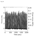
- the shear stress curve shown in FIG. 22 was dominantly affected by the effects, such as due to deformation of a holding member for fixing and supporting the crystal body, within a range from the position of (a) at which the blade came into contact with the crystal body to the position of (b) and within a range from the position of (g) to the position of (h) at which the blade was pulled away from the crystal body. Therefore, after obtaining a state of eliminating the effects, such as due to deformation of the holding member, the shear stress curve of the crystal body according to the present example was measured under an environment of 399.7K ( FIG. 23 ). In addition, as shown in FIG. 24 , the above superelastic transformation in the crystal body according to the present example was reproduced in 50 cycles without elastic reduction or material deterioration.
- the energy storage density of the superelastic material formed of the crystal body according to the present example was estimated to be 26.5 kJm -3 , and the energy storage efficiency ( ⁇ ) was estimated to be 0.766.
- the chemical stress was estimated to be 0.472 MPa, and the superelastic index of the superelastic material was estimated to be about 0.0561.
- the ambient temperature was set to 397K (123.8°C) so that the crystal body would consist of the ⁇ -phase as a whole ("0 s" in FIG. 25 ). This state will be referred to as an "initial state.”
- the shear force 4 was then applied to generate the ⁇ -phase to obtain a ⁇ / ⁇ two-phase coexisting state ("9 s" in FIG. 25 ).
- unloading was performed and it was confirmed that, even after 100 seconds passed from the initial state (i.e. even after 90 seconds or more passed from the unloading), the deformation strain due to applying the shear force 4 was maintained ("100 s" in FIG. 25 ).
- the ambient temperature was raised from 397K (123.8°C) to 398K (124.8°C).
- the crystal body when the ambient temperature was 397.5K (124.3°C) had a reduced volume of the ⁇ -phase compared with that of the crystal body when the ambient temperature was 397K (123.8°C).
- the ⁇ -phase completely vanished and only the ⁇ -phase existed ("150 s" in FIG. 25 ).
- the ambient temperature was set to 298K (25°C) so that the crystal body would consist of the ⁇ -phase as a whole ( FIG. 27(a) ).
- the shear force 4 was then applied, the deformation strain of the ⁇ -phase due to applying the shear force 4 was maintained ( FIG. 27(b) ).
- the crystal body as a whole was heated by raising the ambient temperature.
- the ⁇ -phase was maintained with the deformation strain until the temperature reached 397.5K (124.5°C) ( FIG. 27(c) ) as in FIG. 27(b) .
- the ambient temperature exceeded 398K (125°C)
- the ⁇ -phase was generated in the crystal body as shown in FIG. 27(d)
- the phage change of the ⁇ -phase into the ⁇ -phase rapidly progressed.
- the deformation strain maintained in the crystal body decreased ( FIG. 27(e) ).
- the ambient temperature was then reduced to cool the crystal body of the ⁇ -phase. This resulted in the phase change of the ⁇ -phase into the ⁇ -phase when the ambient temperature was about 397K (124 °C), and this phase change rapidly progressed ( FIG. 27 (g) ).
- the crystal body was caused to consist only of the ⁇ -phase as a low-temperature phase without deformation strain, and when the ambient temperature was room temperature (25°C), the crystal body was restored to have the same phase state and shape as those in FIG. 27(a) .
- a single crystal of (P n Bu 4 ) (BPh 4 ) was obtained in the same manner as in Example 4.
- the dimension was 3 mm ⁇ 6 mm ⁇ 34 mm, and the mass was 0. 61 g.
- the single crystal of (P n Bu 4 ) (BPh 4 ) was supported so that the center of the single crystal was projected with a distance of 30 mm.
- a weight of 100g was hung from a position of 5 mm as the distance from the supporting point using a string, a weight of 10g was hung from a position of 20 mm using a string, and a weight of 1g was hung from a position of 25mm using a string.
- the portion from the supporting point to the hanging position of the 1-g weight was an ⁇ - -phase (daughter phase), and the other portion was an a + -phase (mother phase) ( FIGS. 29 and 29 ).
- the ambient was maintained at 404.2K (131°C).
- the region of the single crystal from the end to the hanging position of the 1-g weight was transformed to the ⁇ -phase ( FIGS. 30 and 31 ).
- the ambient temperature was raised at a rate of 7 ⁇ 10 -3 Ks -1
- the ⁇ -phase of the single crystal grew toward the supporting point, and the 1-g weight continued to be raised.
- the ambient was 405K (131.8°C)
- the ⁇ -phase further grew from the end to the hanging position of the 10-g weight in the single crystal, and the 10-g weight started to be raised ( FIGS. 32 and 33 ).
- the temperature was further raised at a rate of 7 ⁇ 10 -3 Ks -1 to grow the ⁇ -phase.
- the ambient temperature was 406.6K (133.4°C)
- the 100-g weight started to be raised ( FIGS. 34 and 35 ).
- the single crystal became the ⁇ -phase up to the supporting point ( FIGS. 36 and 37 ).
Landscapes
- Chemical & Material Sciences (AREA)
- Organic Chemistry (AREA)
- Engineering & Computer Science (AREA)
- Metallurgy (AREA)
- Materials Engineering (AREA)
- Crystallography & Structural Chemistry (AREA)
- Life Sciences & Earth Sciences (AREA)
- Molecular Biology (AREA)
- General Health & Medical Sciences (AREA)
- Biochemistry (AREA)
- Health & Medical Sciences (AREA)
- Analysing Materials By The Use Of Radiation (AREA)
- Organic Low-Molecular-Weight Compounds And Preparation Thereof (AREA)
Abstract
Description
- The present invention relates to a superelastic material and also to an energy storage material, an energy absorption material, an elastic material, an actuator, and a shape memory material that use the superelastic material.
- Since an Au-Cd alloy was found to exhibit superelasticity in 1932 as disclosed in Non-Patent Literature 1, development of superelastic materials has been performed. In the present description, the "superelasticity" refers to a phenomenon that, when the applied external force is reduced, reverse transformation spontaneously occurs and this reverse transformation releases the energy stored during transformation thereby to finally recover a state that is substantially the same as the state before occurrence of the transformation.
- Various superelastic materials have been developed, including metal-based materials as disclosed in
Patent Literature 1 and oxide ceramic-based materials as disclosed inPatent Literature 2. In the present description, the "superelastic material" means a material that can exhibit superelasticity within a given temperature region. -
- [Patent Literature 1]
JP2006-265680A - [Patent Literature 2]
JP2004-149381A - [Non-Patent Literature 1] Olander, A. An electrochemical investigation of solid cadmium-gold alloys. J. Am. Chem. Soc. 54, 3891-3833 (1932)
- In the superelastic materials as disclosed in
Patent Literature - An object of the present invention is to provide a superelastic material that can exhibit superelasticity even with a reduced amount of energy compared with the conventional superelastic materials. Another object of the present invention is to provide an energy storage material, an energy absorption material, an elastic material, an actuator, and a shape memory material that use the above superelastic material.
- An aspect of the present invention, which is provided to achieve the above objects, is a superelastic material characterized by having a molecular crystal.
- The molecular crystal of the above superelastic material may have an organic skeleton.
- The above superelastic material may be formed of a molecular crystal body or may also be formed of a mixture that includes a molecular crystal body.
- The above molecular crystal body may be a single-crystal body or may also be a polycrystal body.
- The mixture which includes the above molecular crystal body may include the molecular crystal body and a matrix material.
- The superelastic material may preferably have an energy storage density of 1 MJm-3 or less.
- According to another aspect of the present invention, there are provided an energy storage material, an energy absorption material, an elastic material, an actuator, and a shape memory material that each comprise the above superelastic material.
- According to the present invention, there is provided a superelastic material that can exhibit superelasticity even with a reduced amount of energy compared with the conventional superelastic materials. There is also provided an energy storage material, an energy absorption material, an elastic material, an actuator, and a shape memory material that use the above superelastic material.
-
- [
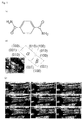
FIG. 1 ] InFIG. 1 , (a) represents the molecular structure of terephthalamide; (b) illustrates a crystal body used for analysis by X-ray diffraction and fixed with resin in a state of being bent under an applied shear force; and (c) is a set of continuous images that show the recovery motion after removal of the shear force (image-capturing interval: 1/120 sec). - [
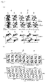
FIG. 2] FIG. 2 is a set of diagrams for explaining phase connection under a shear-induced transition state, wherein (a) is a set of views that illustrate the crystal packing; and (b) is a set of projection images in the [001] (a) direction and the [010] (b) direction. The arrow in (a) indicates the direction of end-to-end coordination of terephthalamide arranged in the longitudinal direction. The broken lines in (a) represent the intermolecular interaction, wherein the black dotted lines each indicate a hydrogen bond between the hydrogen of an amino group and the oxygen of a carbonyl group, and the gray dotted lines each indicate the CH-π interaction between the hydrogen bound to a phenyl group and the carbon of a phenyl group. The angles in (b) are each calculated using a crossing axis of the normal vector of each crystal plane facing the boundary. - [
FIG. 3] FIG. 3 is a set of images of a sample from the side surface observed using a polarization microscope (shift angle from the crossed Nicols angle: 10°), which represent the results of a shear stress test (displacement speed: 500 µm/min, 294K) for the crystal body according to Example 1, wherein the characters and numerals in the images correspond to those inFIGS. 4 and6 . - [
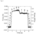
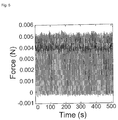
FIG. 4] FIG. 4 is a graph that shows the temporal change in the measured force (unit: N), which represents the result of a shear stress test (displacement speed: 500 µm/min, 294K) for the crystal body according to Example 1, wherein the right-hand side vertical axis in the graph indicates a shear stress (unit: MPa) obtained by normalization with the cross-section area of the single crystal body. - [
FIG. 5] FIG. 5 is a graph that shows, in a similar form to that inFIG. 4 , the result of repeating 100 times the operation to vary the position of a blade which provides the graph shown inFIG. 4 . - [
FIG. 6] FIG. 6 is a graph that shows the relationship between the measured force (unit: N) and the displacement (unit: mm) of the blade, which represents the result of a shear stress test (displacement speed: 500 µm/min, 294K) for the crystal body according to Example 1, wherein the right-hand side vertical axis in the graph indicates a shear stress (unit: MPa) obtained by normalization with the cross-section area of the single crystal body. - [
FIG. 7] FIG. 7 is a graph that shows, in a similar form to that inFIG. 6 , the result of repeating 100 times the operation to vary the position of the blade which provides the graph shown inFIG. 6 . - [
FIG. 8] FIG. 8 is a diagram that shows an average force-displacement curve of the crystal body according to Example 1, which is obtained on the basis of the test ofFIG. 7 , so that the curve can be compared with a typical force-displacement curve of a Ti-Ni alloy. - [
FIG. 9] FIG. 9 is a diagram that shows the simulation result of powder patterns based on the measurement results of X-ray diffraction for the β phase of the crystal body according to Example 1. - [
FIG. 10] FIG. 10 represents the chemical structure of pyrazine-added copper(II) benzoate. - [
FIG. 11 ] InFIG. 11 , (a) is a schematic view that illustrates a shear stress test for the crystal body according to Example 2; and (b) is a set of observation images of the crystal body at respective positions inFIG. 13 . - [
FIG. 12] FIG. 12 is a set of projection images to the surface of which the normal line is the b-axis of the crystal body according to Example 2, which are for explaining phase connection under a shear-induced transition state of the crystal body according to Example 2. - [
FIG. 13] FIG. 13 is a graph that shows the relationship between the measured force (unit: N) and the displacement (unit: mm) of a blade, which represents the result of a shear stress test for the crystal body according to Example 2, wherein the right-hand side vertical axis in the graph indicates a shear stress (unit: MPa) obtained by normalization with the cross-section area of the single crystal body. - [
FIG. 14] FIG. 14 is a graph that shows the result of reproducing 100 times the operation to vary the position of a blade which provides the graph shown inFIG. 13 , wherein the horizontal axis is the elapsed time. - [
FIG. 15] FIG. 15 is a graph that shows, in a similar display form to that inFIG. 13 , the result of reproducing 100 times the operation to vary the position of the blade which provides the graph shown inFIG. 13 . - [
FIG. 16] FIG. 16 represents the molecular structure of 3,5-difluorobenzoic acid. - [
FIG. 17 ] InFIG. 17 , (a) is a schematic view that illustrates a shear stress test for the crystal body according to Example 3; and (b) is a set of observation images of the crystal body at respective positions inFIG. 18 . - [
FIG. 18] FIG. 18 is a graph that shows the temporal change in the measured force (unit: N), which represents the result of a shear stress test for the crystal body according to Example 3, wherein the right-hand side vertical axis in the graph indicates a shear stress (unit: MPa) obtained by normalization with the cross-section area of the single crystal body. - [
FIG. 19] FIG. 19 is a graph that shows the relationship between the measured force (unit: N) and the displacement (unit: mm) of a blade, which represents the result of a shear stress test for the crystal body according to Example 3, wherein the right-hand side vertical axis in the graph indicates a shear stress (unit: MPa) obtained by normalization with the cross-section area of the single crystal body. - [
FIG. 20] FIG. 20 represents the molecular structure of tetrabutylphosphonium tetraphenylborate. - [
FIG. 21 ] InFIG. 21 , (a) is a schematic view that illustrates a shear stress test for the crystal body according to Example 4; and (b) is a set of observation images of the crystal body at respective positions inFIG. 22 . - [
FIG. 22] FIG. 22 is a graph that shows the temporal change in the measured force (unit: N), which represents the result of a shear stress test for the crystal body according to Example 4, wherein the right-hand side vertical axis in the graph indicates a shear stress (unit: MPa) obtained by normalization with the cross-section area of the single crystal body. - [
FIG. 23] FIG. 23 is a graph that shows the temporal change in the measured force (unit: N), which represents the result of a shear stress test for the crystal body according to Example 4, wherein the effect of deformation of a stand that supports the crystal body is eliminated compared with the graph shown inFIG. 22 . - [
FIG. 24] FIG. 24 is a graph that shows the result of reproducing 50 times the operation to vary the position of a blade which provides the graph shown inFIG. 23 , wherein the horizontal axis is the elapsed time. - [
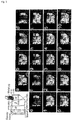
FIG. 25] FIG. 25 is a set of observation images that show the results of a shear stress test performed for the crystal body according to Example 5 while varying the ambient temperature. - [
FIG. 26] FIG. 26 is a DSC chart for tetrabutylphosphonium tetraphenylborate. - [
FIG. 27] FIG. 27 is a set of observation images that show the results of a shear stress test performed for the crystal body according to Example 6 while varying the ambient temperature. - [
FIG. 28] FIG. 28 is an observation image of the crystal body produced in Example 8 when weights are hung from the crystal body in a room temperature environment. - [
FIG. 29] FIG. 29 is a schematic diagram that illustrates the observation image ofFIG. 28 so that the phase distribution of single crystal can be recognized. - [
FIG. 30] FIG. 30 is an observation image of the crystal body produced in Example 8 when the atmosphere for the crystal body is maintained at 404.2K. - [
FIG. 31] FIG. 31 is a schematic diagram that illustrates the observation image ofFIG. 30 so that the phase distribution of single crystal can be recognized. - [
FIG. 32] FIG. 32 is an observation image of the crystal body produced in Example 8 when the atmosphere for the crystal body is raised to 405K. - [
FIG. 33] FIG. 33 is a schematic diagram that illustrates the observation image ofFIG. 32 so that the phase distribution of single crystal can be recognized. - [
FIG. 34] FIG. 34 is an observation image of the crystal body produced in Example 8 when the atmosphere for the crystal body is raised to 406.6K. - [
FIG. 35] FIG. 35 is a schematic diagram that illustrates the observation image ofFIG. 34 so that the phase distribution of single crystal can be recognized. - [
FIG. 36] FIG. 36 is an observation image of the crystal body produced in Example 8 when the atmosphere for the crystal body is raised to 409.2K. - [
FIG. 37] FIG. 37 is a schematic diagram that illustrates the observation image ofFIG. 36 so that the phase distribution of single crystal can be recognized. - Hereinafter, the present invention will be described in detail.
- The superelastic material according to an embodiment of the present invention has a molecular crystal. In the present description, the "molecular crystal" means a crystal in which repetitive elements (unit cells) that constitute the crystal are composed of molecules, and bonds that connect the unit cells comprise bonds (e.g. Van der Waals interaction, hydrogen bond) other than covalent bond-like bonds (including metallic bonds).
- Specific structure of molecules that constitute the unit cells of the molecular crystal according to an embodiment of the present invention is not particularly limited. In view of making it easy for the bonds that connect the unit cells to comprise bonds other than covalent bond-like bonds (including metallic bonds), the above molecular crystal may preferably have an organic skeleton.
- That is, an example of the molecular crystal of the superelastic material according to an embodiment of the present invention may have an organic skeleton. Examples of molecules having an organic skeleton include organic molecules, organic metal molecules (metal complexes may be exemplified as specific examples) and organic-inorganic molecules, and combination thereof, which may include carbon-carbon bonds.
- The superelastic material according to an embodiment of the present invention may comprise a molecular crystal body. In the present description, the "molecular crystal body" means a body that is formed of a molecular crystal. According to the feature that at least a part of the molecular crystal or crystals included in the molecular crystal body of the superelastic material of an embodiment of the present invention can exhibit superelasticity, the superelastic material of an embodiment of the present invention can exhibit superelasticity as the whole material. The molecular crystal body of the superelastic material according to an embodiment of the present invention may be a single-crystal body or may also be a polycrystal body. In the present description, the concept of the term "single-crystal body" encompasses a mosaic crystal and a crystal that includes lattice defects as well as a crystal of which the degree of crystallization is low and a crystal of which the degree of purity is low. In the present description, the term "polycrystal body" means an aggregate of crystals in contrast to a single crystal.
- A specific example of the superelastic material according to an embodiment of the present invention may be formed of a molecular crystal body. Another specific example of the superelastic material according to an embodiment of the present invention may be formed of a mixture that includes a molecular crystal body. The content ratio of the molecular crystal body in the above mixture is not particularly limited, provided that the mixture as a whole can exhibit superelasticity. Specific example of the mixture may be a case in which the mixture includes a molecular crystal body and a matrix material. In this case, the mixture may have a structure in which the molecular crystal body is dispersed in the matrix material, for example, so that the mechanical characteristics of the molecular crystal body dominate the mechanical characteristics of the mixture as a whole, and the mixture as a whole appears to be able to exhibit superelasticity. Here, the relation between the matrix material and molecular crystal body of the mixture is not limited. The matrix material may have a larger volume than that of the molecular crystal body, a comparable volume to that of the molecular crystal body, or a smaller volume than that of the molecular crystal body. The degree of interaction between the matrix material and molecular crystal body of the mixture is also not limited. The matrix material and the molecular crystal body may be unified, such as that the substance which constitutes the matrix material is associated with or chemically bound to the substance which constitutes the molecular crystal body. Such an example may be a case in which the mixture comprises a crosslinked structure of the matrix material and molecular crystal body. Another example may be a case in which the mixture comprises a high-molecular substance, and partial structures (e.g. side chains) of the high-molecular substance are spatially arranged in a regular manner, such as due to aggregation. In this case, the partial structures arranged in a regular manner belong to the molecular crystal body, and portions that are not arranged in a regular manner in the high-molecular substance belong to the matrix material.
- The superelastic material according to an embodiment of the present invention may involve a loading transformation process and an unloading reverse transformation process. In the present description, the "loading transformation process" means a process in which, when an external force is applied to the superelastic material according to an embodiment of the present invention, the applied external force triggers transformation and progresses the transformation. In the present description, the "unloading reverse transformation process" means a process in which reducing the external force applied to the superelastic material in the state where the loading transformation process progresses triggers reverse transformation, and the reduced external force progresses the reverse transformation.
- Temperature range within which the reverse transformation readily occurs in the superelastic material according to the present embodiment is not particularly limited. When thermoelastic martensitic transformation occurs in the superelastic material according to the present embodiment, the stress-induced phase may be destabilized within a temperature region of which the lower limit value is equal to the reverse transformation finishing temperature, so that the reverse transformation is likely to occur. In contrast, the stress-induced phase can stably exist within a temperature region of the reverse transformation starting temperature or lower, so that the reverse transformation is less likely to occur. Therefore, when the thermoelastic martensitic transformation occurs in the superelastic material and an external force is applied thereto within a temperature region of the reverse transformation starting temperature or lower, the strain caused by the external force may remain in the superelastic material. Thereafter, if the material in which the strain remains is heated to a temperature of the reverse transformation finishing temperature or higher, the reverse transformation may recover the strain. Thus, when the thermoelastic martensitic transformation occurs in the superelastic material according to the present embodiment, the shape-memory effect of the superelastic material can be observed. In the superelastic material having a molecular crystal according to the present embodiment, the molecules that constitute the unit cells may be appropriately selected such that the reverse transformation can readily occur at the room temperature (23°C) or otherwise cannot readily occur at the room temperature.
- The degree of superelasticity possessed by the superelastic material can be evaluated in accordance with some parameters.
- An example of such parameters may be an energy storage density. The energy storage density refers to a value (unit: Jm-3) obtained by dividing work, which is done by the superelastic material when the amount of displacement is reduced and which can be obtained from a force-displacement curve, by a volume before transformation of a transformed portion of the superelastic material in a state in which the amount of displacement is maximum. The energy storage density in a Ti-Ni alloy, which is a typical example of the conventional metal-based superelastic material, may be 14 MJm-3, i. e. 10 MJm-3 order. In contrast, the energy storage density of the superelastic material according to an embodiment of the present invention may be 1 MJm-3 or less, the energy storage density of a preferred example of the superelastic material according to an embodiment of the present invention may be 0.2 MJm-3 or less, the energy storage density of another preferred example of the superelastic material according to an embodiment of the present invention may be 0.1 MJm-3 or less, and the energy storage density of still another preferred example of the superelastic material according to an embodiment of the present invention may be 50 kJm-3 or less.
- Another example of the above parameters may be a chemical stress. The chemical stress refers to an average value (unit: Pa) of a stress calculated from an external force, which is applied in a state where the variation in numerical value of the external force apparently becomes small as the transformation progresses and which can be obtained from a force-displacement curve in the loading transformation process, and a recovery force which is generated in a state where the variation in numerical value of the recovery force apparently becomes small as the reverse transformation progresses and which can be obtained from a force-displacement curve in the unloading reverse transformation process. The chemical stress in a Ti-Ni alloy, which is a typical example of the conventional metal-based superelastic material, may be 558 MPa, i.e. the order of 100 MPa to 1 GPa. In contrast, the chemical stress of the superelastic material according to an embodiment of the present invention may be 10 MPa or less, and the chemical stress of a preferred example of the superelastic material according to an embodiment of the present invention may be 1 MPa or less. As the chemical stress decreases, the external force required for exhibiting the superelasticity tends to become low, and the superelastic material can readily be applied to microstructures.
- Still another example of the above parameters may be a superelastic index. The superelastic index refers to a value (unit: dimensionless) obtained by dividing the energy storage density by the chemical stress. The superelastic index of a Ti-Ni alloy, which is a typical example of the conventional metal-based superelastic material, may be about 0.025, i.e. less than 0.05. In contrast, the superelastic index of the superelastic material according to an embodiment of the present invention may be 0.05 or more, and the superelastic index of a preferred example of the superelastic material according to an embodiment of the present invention may be 0.1 or more. It can be said that, the higher the superelastic index is, the more efficient the superelastic material is, i.e., the superelastic material can store a large amount of energy even with a small external force applied. Therefore, the superelastic material according to an embodiment of the present invention, which has a higher superelastic index than that of the conventional superelastic material, can be expected to be readily applied to microstructures.
- In the superelastic material according to an embodiment of the present invention, the transformation can occur to have a large displacement with a small input of energy. In other words, it can be said that a small output can be uniformly achieved with large reverse transformation. Therefore, the following uses are expected:
- an energy storage material that comprises the superelastic material according to an embodiment of the present invention;
- an energy absorption material that comprises the superelastic material according to an embodiment of the present invention;
- an elastic material that comprises the superelastic material according to an embodiment of the present invention;
- an actuator that comprises the superelastic material according to an embodiment of the present invention; and
- a shape memory material that comprises the superelastic material according to an embodiment of the present invention.
- Hereinafter, effects of the present invention will be described with reference to examples, but the present invention is not limited to these examples.
- A well-formed single crystal of terephthalamide was obtained by recrystallization of reagent-grade terephthalamide from warm water. A crystal body obtained by drying the single crystal in a vacuum was used in the test. When a shear force (referred to as "
shear force 1," hereinafter) was applied on the {010} crystal surface of the crystal body, the crystal body was bent and another crystal phase was generated therein. The boundary between the original crystal phase and the generated other crystal phase was sharp. When the crystal body was continued to be pushed, i.e., when theshear force 1 was continued to be applied, the bending position at the phase boundary in the crystal body transferred as shown inFIG. 1 . - When applying the
shear force 1 was removed, the bent crystal body spontaneously restored, and the phase boundary, which moved due to applying theshear force 1, transferred back with a speed of 3.33 mm/sec at 294K. - X-ray diffraction measurement was performed for the crystal body in a state of being applied with the
shear force 1. From the results, the shear force-induced transition from a mother phase (α-phase) to a daughter phase (β-phase) was observed (FIG. 1 ) . While both of the α-phase and the β-phase had the same P-1-type crystal system, the crystal packing was significantly different. The crystal structure of the α-phase was a structure that was already known, the structure of the β-phase was a structure that was not known. - In the α-phase, a plurality of terephthalamide molecules gathered to form polymeric sheets. In the sheets, the terephthalamide molecules constituted a network structure in which the terephthalamide molecules were bound by hydrogen bonds between NH portions and O=C portions. The distance between N and O of the hydrogen bond formed of NH and O=C of the ends along the longitudinal axis of terephthalamide was 2.932(4) Å, and the distance between N and O of the hydrogen bond formed of NH and O=C of ad j a cent terephthalamide molecules, i.e. molecules located at positions in the direction perpendicular to the longitudinal axis in the sheets, was 2.912(3) Å.
- In the change from the α-phase to the β-phase due to applying the
shear force 1, the sheets formed of a uniform -A-A-A-A- arrangement transformed into sheets formed of an alternative -A'-B-A'-B- arrangement. As illustrated inFIG. 2 , the β-phase had a structure in which columns A' substantially maintaining the structure of A were sandwiched by the deformed columns B. - The change in the molecular arrangement from the α-phase into the β-phase achieved a relatively denser packing state. Specifically, the density of the α-phase was 1.470 Mg/m-3, and the density of the β-phase was 1.484 Mg/m-3. In the β-phase, the terephthalamide molecules also constituted a network structure in which the terephthalamide molecules were bound by hydrogen bonds between NH and O=C. The change in the hydrogen bond distance was slightly observed. The distance between N and O of the hydrogen bond formed of NH and O=C of the ends along the longitudinal axis of terephthalamide was 2.943 (5) Å in the column A' and 2.918 (5) Å in the column B. With regard to the hydrogen bond formed of NH and O=C of terephthalamide molecules located at positions in the direction perpendicular to the longitudinal axis in the sheets, the distance between N and O of the hydrogen bond formed of NH in the column A' and O=C in the column B was 3.007 (4) Å, and the distance between N and O of the hydrogen bond formed of NH in the column B and O=C in the column A' was 2.965(4) Å.
- As illustrated in
FIG. 2 , additional interaction was recognized in the β-phase. In the sheets, CH-n interaction was recognized, which was specifically the interaction between H bound to a phenyl group in the column B and C of a phenyl group in the column A'. The distance between C of the phenyl group to which H was bound in the column B and C of the phenyl group in the column A' was 3.471 (6) Å.The manner of layer stack of the phenyl groups changed between in the α-phase and in the β-phase. In the α-phase, the phenyl groups were weakly stacked in the column A in which the surface separation of the phenyl groups was 3,500 Å, resulting in a stack structure having high two-dimensionality. Whereas in the β-phase, the surface separation of the phenyl groups was significantly shortened to 3,209 Å in the column A', and an intermolecular interaction network was formed three-dimensionally. - The heterophase boundary (martensite habit plane) parallel with the (100) plane of the α-phase was almost perpendicular to the (011) plane as the cleavage plane of the α-phase. The (011) plane of the α-phase was a plane that lay in the sheets constituted of hydrogen bonds.
- The disparity between the habit plane and the cleavage plane allowed the transformation stable against the distortion around the heterophase interface.
- From the data of X-ray diffraction for the crystal body in the bending form, it was estimated how each crystal fitted at the interface under the α-phase/β-phase coexistent state. In the interface between the (100) plane of the α-phase and the (00-1) plane of the β-phase, the ratio of facing area (Sα/Sβ) was 0.989, which raises the Bain distortion. It appeared that, at the interface, the crystal face of the α-phase and the crystal face of the β-phase respectively received face contraction and extension. In detail, a certain difference was recognized in the length of c-axis of the α-phase (7.1853 Å) and b-axis of the β-phase (7.268 Å), and the difference indicates the mainly unidirectional distortion along the c-axis in the bc face and a unidirectional distortion along the b-axis in the ab face, respectively.
- The deduced connection views at the interfaces (
FIG. 2 ) revealed that the martensitic transformation occurred in the observed twinning transformation in the crystal body. The views also showed the possibility that the [010] direction and [00-1] direction in the α-phase is effective for shear-induced twinning transformation. - The bending angle of the crystal body observed using a microscope was within a range of 5° to 8° judged from the projection direction of [001] and within a range of 3° to 5° judged from the projection direction of [010]. These angles agree approximately with the angles expected from the X-ray diffraction data (6.55° and 5.35°) (
FIG. 2 ). - The proportion in the displacements, obtained by the microscope observation, of the
shear force 1 applying position onto the (010) surface of the α-phase and the moving position (farther from the position applied with the shear force 1) of the β-phase/α-phase interface was 1:6.7. This proportion agrees approximately with the expected proportion (1:5.4) using the X-ray diffraction data. - The agreement to these parameters demonstrates the harmonious support of the microscopic structural change and the macroscopic structural change in the crystal body according to the present example.
- The relationship between the shear force and the deformation was investigated by applying a load to a part of the {010} crystal surface. The load in this direction appears to be nearly parallel to the shear-transition easy axis (see
FIG. 2 ). One end portion of a crystal body (thickness of 149.52 µm and width of 58.84 µm) formed of the above single crystal of terephthalamide was fixed, and a metallic blade of a width of 25 µm was made to come into contact with the (010) surface of the crystal body and pushed across the surface at a constant speed of 500 µm/min at 294K. This resulted in the twinning transformation of the crystal body as shown inFIG. 3 . - As shown in
FIG. 4 , stress was detected at the position of (a) after the blade reached the crystal body. Thereafter, the phase boundary began to increase as the load increased (images denoted bynumerals 1 to 5 inFIG. 3 ). The stress became constant at (b) ofFIG. 4 where a thin band of β-phase was generated from the contact portion of the blade. - Subsequently, as shown in (c) and (d) of
FIG. 4 , the state of a stable stress value continued during the growth and propagation of the β-phase by continuous proceeding of the α-phase/β-phase transition. - (e) of
FIG. 4 is the switching point for the unloading process (pulling back the blade), and a slight decrease in the stress was observed. Thereafter, the state of a stable stress value continued during the phase change of the β-phase into the α-phase. At (h) ofFIG. 4 , the region of β-phase narrowed to be a boundary line. From this point, the stress was linearly decreased until the blade was removed from the surface of the crystal body at (i) ofFIG. 4 , and during this period, a phenomenon occurred that the line-like boundary decreased and vanished (images denoted bynumerals 6 to 10 inFIG. 3 ). - The shear stress curve thus obtained (
FIG. 4 ) clearly demonstrated that the crystal body according to the present example exhibited superelasticity. - As shown in
FIG. 5 , the above superelastic transformation in the crystal body according to the present example was reproduced in 100 cycles of measurement without any elastic reduction or material deterioration. - As a result of the cyclic test on crystal bodies formed of single crystals with different dimensions, the strength of stress generated under the bending state of the crystal bodies was linear with the surface area of the phase boundary, and was not correlated with the contact surface area with the blade. This result means that the elastic index as for shear should be normalized by a parameter that is obtained by dividing the absolute force by the surface area of the α-phase/β-phase boundary. The above parameter corresponds to a shear stress that is obtained by dividing the external force by the cross-sectional area of the crystal body. From
FIG. 4 , the shear stress in the transformation (from the α-phase to the β-phase) of the superelastic material formed of the crystal body according to the present example was 0.496 MPa, and the shear stress in the reverse transformation (from the β-phase to the α-phase) was 0.459 MPa. This shear stress was about one thousand times smaller than 558 MPa, which is known as the shear stress of a typical Ti-Ni alloy. The chemical stress, which is the average value of the shear stress at the position of (b) and the shear stress at the position of (h) inFIG. 6 , was 0.477 MPa. - The energy storage density and energy storage efficiency (η) of the superelastic material formed of the crystal body according to the present example were estimated to be 0.062 MJm-3 and 0.925, respectively. The superelastic index of the superelastic material formed of the crystal body according to the present example was estimated to be about 0.13.
- The movable range of superelastic shear strain was wide, and the ratio of the displacement amount to the crystal size was up to 11.34%. This numerical value can be predicted by the geometric arrangement of the junction of adjacent crystal lattices with the X-ray diffraction data.
- The superelastic material formed of a single crystal body of terephthalamide according to the present example is a pure organic crystal body, i.e. an organic crystal body that does not have an inorganic component such as metal elements. As described above, its energy storage density is 0.062 MJm-3, which is 226 times less than the energy storage density of a typical Ti-Ni alloy (14 MJm-3). When the above energy storage density is converted to an amount per mol, the energy storage density of the superelastic material formed of a single crystal body of terephthalamide is 6.96 Jmol-1 while the energy storage density of a typical Ti-Ni alloy is 114.76 Jmol-1, and the ratio thereof is 1:16.5. This ratio agrees approximately with 1:15.9 which is the ratio in the bonding energy of the superelastic material formed of a single crystal body of terephthalamide (4 times the bonding energy between NH and O=C = 28.87 kJmol-1×4) to the bonding energy of Ti-Ni alloy (458.83 kJmol-1×4). Thus, the energy storage ability is related to the lattice energy. The volumetric energy density may become relatively smaller by the extent of the lattice. Consequently, the superelastic molecular material provided according to the present example can produce a transformation with a large displacement from a small energy input. In other words, it can be said that the superelastic molecular material can generate a uniform level of small power with a large reverse transformation.
- Table 1 shows the measurement results of X-ray diffraction for the β-phase of the superelastic material formed of a crystal body of terephthalamide according to the present example. The measurement was performed using an X-ray diffractometer, Smart APEX CCD, available from Bruker Corporation.
[Table 1] Empirical formula C8 H8 N2 O2 Formula weight 164.16 Temperature 298 K Wavelength 0.71073 Å Crystal system Triclinic Space group P-1 Unit cell dimensions a = 5.3663(17) Å a= 104.149(7)°. b = 7.268(2) Å b= 97.699(7)°. c = 10.160(3) Å g = 102.672(7)°. Volume 367.4(2) Å3 Z 2 Density (calculated) 1.484 Mg/m3 Absorption coefficient 0.110 mm-1 F(000) 172 Crystal size 0.13x0.11 x0.04mm3 Theta range for data collection 2.11 to 25.01°. Index ranges -6<=h<=6, -7<=k<=8, -12<=l<=11 Reflections collected 2118 Independent reflections 1295 [R(int) = 0.0284] Completeness to theta = 25,01° 99,50% Absorption correction Empirical Max. and min. transmission 0.9956 and 0.9859 Refinement method Full-matrix least-squares on F2 Data / restraints / parameters 1295/0/109 Goodness-of-fit on F2 1.125 Final R indices [l>2sigma(l)] R1 = 0.0868, wR2 = 0.2292 R indices (all data) R1 = 0.1045, wR2 = 0.2468 Largest diff. peak and hole 0.550 and -0.412 e.Å-3 -
FIG. 9 shows the simulation result of powder patterns performed on the basis of the above data. - A single crystal of pyrazine-added copper(II) benzoate having a chemical structure shown in
FIG. 10 was produced using the method as described in Patent No.4951728 shear force 2," hereinafter) was applied on the {00-1} crystal surface of the crystal body, the crystal body was bent and another crystal phase was generated therein. The boundary between the original crystal phase and the generated other crystal phase was sharp. When the crystal body was continued to be pushed, i.e., when theshear force 2 was continued to be applied, the bending position at the phase boundary in the crystal body transferred as shown inFIG. 11 . When applying theshear force 2 was removed, the bent crystal body spontaneously restored, and the phase boundary, which moved due to applying theshear force 2, proceeded in the opposite direction. - X-ray diffraction measurement was performed for the crystal body in a state of being applied with the
shear force 2. From the results, the shear force-induced transition from a mother phase (α(trans)-phase) to a daughter phase (α'(trans)-phase) was observed (FIG. 12 ). The bending angle expected from the X-ray diffraction data was 14.6°. - The relationship between the shear force and the deformation was investigated by applying a load to a part of the {00-1} crystal surface. One end portion of a crystal body formed of the above single crystal of pyrazine-added copper (II) benzoate was fixed, and a metallic blade of a width of 25 µm was made to come into contact with the (00-1) surface of the crystal body and pushed across the surface at a constant speed of 500 µm/min at 294K.
- As a result, the stress was detected at the position of (a) as shown in
FIG. 13 after the blade reached the crystal body. Thereafter, the stress increased substantially in proportion to the displacement amount of the blade. Phase transition did not occur in this process, but the daughter phase was generated due to phase transition at the position of (b), and decrease in the stress was measured until the position (c) where the displacement amount of the blade slightly increased. This resulted in a structure in which a mother phase, daughter phase and mother phase were arranged in this order. The plane of the daughter phase interposed between the (00-1) planes of the two mother phases was (100) plane. When the displacement amount of the blade was further increased from the position of (c), the stress increased very little, and the daughter phase grew (i.e., transition from the mother phase to the daughter phase progressed). - (d) in
FIG. 13 is the switching point for the unloading process (pulling back the blade), and a slight decrease in the stress was observed. Thereafter, the state of a stable stress value continued, during the phase change of the daughter phase into the mother phase. At (e) ofFIG. 13 , the region of daughter phase narrowed to be a boundary line between two mother phases. The line-like boundary then vanished at (f) ofFIG. 13 . - The shear stress curve thus obtained (
FIG. 13 ) clearly demonstrated that the crystal body according to the present example exhibited superelasticity. - As shown in
FIGS. 14 and15 , the above superelastic transformation in the crystal body according to the present example was reproduced in 100 cycles without any elastic reduction or material deterioration. - The energy storage density and energy storage efficiency (η) of the superelastic material formed of the crystal body according to the present example were estimated to be 0.0404 MJm-3 and 0.0539, respectively. The chemical stress, which is the average value of the shear stress at the position of (c) and the shear stress at the position of (e) in
FIG. 13 , was 0.146 MPa. The superelastic index of the superelastic material formed of the crystal body according to the present example was estimated to be about 0.277. - The 3,5-difluorobenzoic acid (
FIG. 16 ) was recrystallized from warm water, and a well-formed single crystal of 3,5-difluorobenzoic acid was thereby obtained. A crystal body obtained by drying the single crystal in a vacuum was used in the test. When a shear force (referred to as "shear force 3," hereinafter) was applied on the {011} crystal surface of the crystal body, the crystal body was bent and another crystal phase was generated therein. The boundary between the original crystal phase and the generated other crystal phase was sharp. When the crystal body was continued to be pushed, i.e., when theshear force 3 was continued to be applied, the bending position at the phase boundary in the crystal body transferred as shown inFIG. 17(b) . When applying theshear force 3 was removed, the bent crystal body spontaneously restored, and the phase boundary, which moved due to applying theshear force 3, proceeded in the opposite direction. - X-ray diffraction measurement was performed for the crystal body in a state of being applied with the
shear force 3. The results are listed in Table 2. The measurement was performed using an X-ray diffractometer, Smart APEX CCD, available from Bruker Corporation.[Table 2] Empirical formula C7H4F2O2 C7H4F2O2 C7H4F2O2 Morphology Straight Bent(a+/a-) Crystal phase a a+ a- Empirical formula C7H4F2O2 C7H4F2O2 C7H4F2O2 Crystal size /mm3 0.78x0.12x0.10 0.19×0.19×0.06 0.20x0.19x0.06 M 158.1 158.1 158.1 Crystal system Monoclinic Monoclinic Monoclinic Space group P21/c P21/c P21/c T/K 298 298 298 a/Å 3.7616(15) 3.772(3) 3.7717(18) b/Å 13.365(5) 13.396(9) 13.385(7) c/Å 14.003(6) 14.040(10) 14.005(7) a /deg 90 90 90 b /deg 93.749(9) 93.776(14) 93.884(11) g /deg 90 90 90 V/Å3 702.5(5) 707.9(9) 705.4(6) Z 4 4 4 Dcalcd / Mg m-3 1.495 1.483 1.489 m(Mo Ka) / mm-1 0.143 0.142 0.142 Reflections collected 3986 3839 5010 Independent reflections (Rint) 1250(0.1004) 1254(0.0824) 1733(0.0714) Goodness of fit 1.051 0.96 0.937 R1(I > 2s (all data)) 0.0856(0.1974) 0.0776(0.1692) 0.0934(0.2166) wR2(I > 2s (all data)) 0.2242(0.2694) 0.1773(0.2381) 0.2196(0.3075) Largest diff. peak (hole) /eÅ3 0.215(-0.259) 0.250(-0.313) 0.509(-0.390) - The shear force-induced twinning transition from a mother domain (α+-phase) to a daughter domain (α--phase) was observed (
FIG. 17(a) ). - The relationship between the shear force and the deformation was investigated by applying a load to a part of the {011} crystal surface. One end portion of a crystal body formed of the above single crystal of 3,5-difluorobenzoic acid was fixed, and a metallic blade of a width of 25 µm was made to come into contact with the (011) surface of the crystal body and pushed across the surface at a constant speed of 500 µm/min at 294K.
- As a result, the stress was detected at the position of (a) as shown in
FIGS. 18 and19 after the blade reached the crystal body. Thereafter, the stress increased substantially in proportion to the displacement amount of the blade. Twinning transformation did not occur in this process, but the daughter domain was generated due to twinning transformation at the position of (b), and decrease in the stress was measured until the position (c) where the displacement amount of the blade slightly increased. This resulted in a structure in which a mother domain, daughter domain and mother domain were arranged in this order. When the displacement amount of the blade was further increased from the position of (c), the stress increased very little, and the daughter domain grew (i. e. , transition from the mother domain to the daughter domain progressed). The bending angle estimated from the X-ray diffraction data was 27.8°. - (d) in
FIGS. 18 and19 is the switching point for the unloading process (pulling back the blade), and a considerable amount of decrease in the stress was observed to the position of (e) after the unloading. Thereafter, the stress moderately decreased (position (f)), and during this period, the twinning generation from the daughter domain into the mother domain occurred. The daughter domain then vanished at the position (g). - The shear stress curve thus obtained (
FIG. 19 ) clearly demonstrated that the crystal body according to the present example exhibited superelasticity. - The energy storage density and energy storage efficiency (η) of the superelastic material formed of the crystal body according to the present example were estimated to be 0.0119 MJm-3 and 0.178, respectively. The chemical stress, which is the average value of the shear stress at the position of (c) and the shear stress at the position of (g) in
FIG. 19 , was 0.0453 MPa. The superelastic index of the superelastic material formed of the crystal body according to the present example was estimated to be about 0.263. - The tetrabutylphosphonium tetraphenylborate (
FIG. 20 , denoted as "(PnBu4) (BPh4)," hereinafter) was recrystallized from warm water, and a good single crystal of (PnBu4) (BPh4) was thereby obtained. A crystal body obtained by drying the single crystal in a vacuum was used in the test. When a shear force (referred to as "shear force 4," hereinafter) was applied on the {0-10} crystal surface of the crystal body in an environment of 400K, the crystal body was bent and another crystal phase was generated therein. The boundary between the original crystal phase and the generated other crystal phase was sharp. When the crystal body was continued to be pushed, i.e., when theshear force 4 was continued to be applied, the bending position at the phase boundary in the crystal body transferred as shown inFIG. 21(b) . When applying theshear force 4 was removed, the bent crystal body spontaneously restored, and the phase boundary, which moved due to applying theshear force 4, proceeded in the opposite direction. - X-ray diffraction measurement was performed for the crystal body in a state of being applied with the
shear force 4. The results are listed in Table 3. The measurement was performed using an X-ray diffractometer, Smart APEX CCD, available from Bruker Corporation.[Table 3] Empirical formula C40H56BP C40H56BP C40H56BP Phase α α β Temperature /K 298 394 403 Crystal size /mm3 0.75x0.16x0.09 0.46x0.14x0.11 1.00x0.24x0.23 M 578.63 578.63 578.63 Crystal system Triclinic Triclinic Monoclinic Space group P-1 P-1 P21/n a/Å 10.311(3) 10.5582(11) 12.1401(14) b/Å 18.895(5) 19.131(2) 36.975(4) c /A 20.770(6) 20.915(2) 17.688(2) a /° 69.618(7) 68.892(2) 90 β/° 85.946(7) 85.501(3) 102.611(2) γ/° 76.898(6) 77.175(2) 90 V/Å3 3694.1(18) 3842.7(7) 7748.1(15) Z 4 4 8 Dcalcd/Mgm3 1.04 1 0.992 µ(Mo Kα)mm-1 0.099 0.095 0.094 Reflections collected 21495 22471 57189 Independent reflections (R int) 12972 (0.0459) 13522 (0.0410) 19194 (0.0892) Goodness of fit 1.12 0.894 1.123 R 1(I > 2σ (all data)) 0.1120 (0.2319) 0.0960(0.2774) 0.1668 (0.4430) w R 2(I > 2σ (all data)) 0.3496 (0.4207) 0.2660 (0.3982) 0.4463 (0.5654) Leastdiff.peak (hole) /eÅ3 0.443 (-0.336) 0.421 (-0.264) 0.476 (-0.265) - The shear force-induced transition from a mother phase (high-temperature phase β) to a daughter phase (low-temperature phase α) was observed (
FIG. 21(a) ). - The relationship between the shear force and the deformation was investigated by applying a load to a part of the {0-10} crystal surface. One end portion of a crystal body formed of the above single crystal of (PnBu4) (BPh4) was fixed, and a metallic blade of a width of 25 µm was made to come into contact with the (0-10) surface of the crystal body and pushed across the surface at a constant speed of 500 µm/min at 400K.
- As a result, the stress was detected at the position of (a) as shown in
FIG. 21 after the blade reached the crystal body. Thereafter, the stress increased substantially in proportion to the displacement amount of the blade. Phase transition did not occur in this process, but the daughter phase was generated in the mother phase due to phase transition at the position of (b). As the displacement amount of the blade increased, the phase boundaries grew in the direction of applying theshear force 4. This resulted in a structure, at the position (d), in which a mother phase, daughter phase and mother phase were arranged in this order in the direction perpendicular to the direction of applying theshear force 4. When the displacement amount of the blade was further increased from the position of (d), the daughter phase grew in that structure. That is, in this process, the transition from the mother phase to the daughter phase progressed in the direction perpendicular to the direction of applying theshear force 4. - (e) in
FIG. 21 is the switching point for the unloading process (pulling back the blade), and the phase change of the daughter phase into the mother phase progressed in the direction perpendicular to the direction of applying theshear force 4 to the position of (f) after the unloading. Thereafter, from the position of (f) to the position of (g), the phase change from the daughter phase into the mother phase progressed in the direction of applying theshear force 4. The daughter phase then vanished at the position (g). - The shear stress curve thus obtained (
FIG. 22 ) clearly demonstrated that the crystal body according to the present example exhibited superelasticity within a range from the position of (b) to the position of (g) via the position of (e). - Here, the shear stress curve shown in
FIG. 22 was dominantly affected by the effects, such as due to deformation of a holding member for fixing and supporting the crystal body, within a range from the position of (a) at which the blade came into contact with the crystal body to the position of (b) and within a range from the position of (g) to the position of (h) at which the blade was pulled away from the crystal body. Therefore, after obtaining a state of eliminating the effects, such as due to deformation of the holding member, the shear stress curve of the crystal body according to the present example was measured under an environment of 399.7K (FIG. 23 ). In addition, as shown inFIG. 24 , the above superelastic transformation in the crystal body according to the present example was reproduced in 50 cycles without elastic reduction or material deterioration. - On the basis of the shear stress curve shown in
FIG. 23 , the energy storage density of the superelastic material formed of the crystal body according to the present example was estimated to be 26.5 kJm-3, and the energy storage efficiency (η) was estimated to be 0.766. Similarly on the basis of the shear stress curve shown inFIG. 23 , the chemical stress was estimated to be 0.472 MPa, and the superelastic index of the superelastic material was estimated to be about 0.0561. - The relationship between the shear force and deformation of a crystal body formed of the single crystal of (PnBu4) (BPh4) was further investigated by applying a load to a part of the {0-10} crystal surface in the same manner as in Example 4 and varying the ambient temperature.
- First, the ambient temperature was set to 397K (123.8°C) so that the crystal body would consist of the β-phase as a whole ("0 s" in
FIG. 25 ). This state will be referred to as an "initial state." Theshear force 4 was then applied to generate the α-phase to obtain a β/α two-phase coexisting state ("9 s" inFIG. 25 ). Subsequently, unloading was performed and it was confirmed that, even after 100 seconds passed from the initial state (i.e. even after 90 seconds or more passed from the unloading), the deformation strain due to applying theshear force 4 was maintained ("100 s" inFIG. 25 ). - During the period (50 seconds) from when 100 seconds passed to when 150 seconds passed after the initial state, the ambient temperature was raised from 397K (123.8°C) to 398K (124.8°C). As shown in "125 s" of
FIG. 25 , the crystal body when the ambient temperature was 397.5K (124.3°C) had a reduced volume of the α-phase compared with that of the crystal body when the ambient temperature was 397K (123.8°C). In the state after 150 seconds passed from the initial state, the α-phase completely vanished and only the β-phase existed ("150 s" inFIG. 25 ). - Thereafter, during the period to when 159 seconds passed from the initial state, the ambient temperature was maintained at 398K (124.8°C), and applying the
shear force 4 and unloading were performed. As a result, it was confirmed that applying theshear force 4 allowed the α-phase to be formed in the crystal body of the β-phase ("155 s" inFIG. 25 ) and unloading theshear force 4 allowed the α-phase in the crystal body to vanish ("159 s" inFIG. 25 ). - For reference, a DSC (differential scanning calorimetry) chart of (PnBu4) (BPh4) is shown in
FIG. 26 , and the measurement results are listed in Table 4.[Table 4] Crystal Phase transition (α to β) Melting (fusion of β crystal) Index temperature Tα-β/°C ΔH/kJmol-1 ΔS/ JK-1mol-1 Tm/°C ΔH/kJmol-1 ΔS/JK-1mol-1 As(Af)/ °C Ms(Mf)/°C As-Ms (PBu4)(BPh4) 122.9 3.01 7.6 230.1 41 81.4 123 (124.97) 120.46 (118.55) 2.54 - The relationship between the shear force and deformation of a crystal body formed of the single crystal of (PnBu4) (BPh4) was further investigated by applying a load (shear force 4) to a part of the {-101} crystal surface of the α-phase, which is a crystal surface corresponding to the {0-10} crystal surface of the β-phase, in the same manner as in Example 4, and varying the ambient temperature in a different profile from that for Example 5.
- First, the ambient temperature was set to 298K (25°C) so that the crystal body would consist of the α-phase as a whole (
FIG. 27(a) ). When theshear force 4 was then applied, the deformation strain of the α-phase due to applying theshear force 4 was maintained (FIG. 27(b) ). - Subsequently, the crystal body as a whole was heated by raising the ambient temperature. As a result, the α-phase was maintained with the deformation strain until the temperature reached 397.5K (124.5°C) (
FIG. 27(c) ) as inFIG. 27(b) . When the ambient temperature exceeded 398K (125°C), the β-phase was generated in the crystal body as shown inFIG. 27(d) , and the phage change of the α-phase into the β-phase rapidly progressed. As the phase change progressed, the deformation strain maintained in the crystal body decreased (FIG. 27(e) ). When the ambient temperature was approximately 400K (126.6°C), the phase change of the α-phase as a low-temperature phase into the β-phase as a high-temperature phase was completed in the crystal body as shown inFIG. 27(f) , and the deformation strain maintained in the crystal body completely vanished. From the above observation, the shape restoration (shape memory effect) due to temperature raise was confirmed. - The ambient temperature was then reduced to cool the crystal body of the β-phase. This resulted in the phase change of the β-phase into the α-phase when the ambient temperature was about 397K (124 °C), and this phase change rapidly progressed (
FIG. 27 (g) ). When the ambient temperature was further reduced, the crystal body was caused to consist only of the α-phase as a low-temperature phase without deformation strain, and when the ambient temperature was room temperature (25°C), the crystal body was restored to have the same phase state and shape as those inFIG. 27(a) . - As described above, the crystal shape restoration cycle due to heat was confirmed from the present example.
- Applying a shear force to the {0-10} crystal surface of the crystal body and unloading were performed in different temperature environments to obtain a shear stress curve at each temperature. From each shear stress curve, the energy storage density (or energy density), energy storage efficiency (η) (or energy efficiency) and superelastic index were obtained. Results are listed in Table 5.
[Table 5] Temperature (K) Energy density (kJ m-3) Energy efficiency Superelastic index 396.7 3.68 0.0556 0.0681 397.2 9.19 0.333 0.0808 397.7 14.2 0.5 0.0832 398.2 18.9 0.536 0.0773 398.7 21.6 0.629 0.0666 399.2 21.9 0.756 0.0562 399.7 26.5 0.766 0.0561 - A single crystal of (PnBu4) (BPh4) was obtained in the same manner as in Example 4. The dimension was 3 mm×6 mm×34 mm, and the mass was 0. 61 g. In a room temperature environment (25°C), the single crystal of (PnBu4) (BPh4) was supported so that the center of the single crystal was projected with a distance of 30 mm. A weight of 100g was hung from a position of 5 mm as the distance from the supporting point using a string, a weight of 10g was hung from a position of 20 mm using a string, and a weight of 1g was hung from a position of 25mm using a string. In this state, the portion from the supporting point to the hanging position of the 1-g weight was an α--phase (daughter phase), and the other portion was an a+-phase (mother phase) (
FIGS. 29 and 29 ). - In this state, the ambient was maintained at 404.2K (131°C). As a result, the region of the single crystal from the end to the hanging position of the 1-g weight was transformed to the β-phase (
FIGS. 30 and 31 ). Thereafter, when the ambient temperature was raised at a rate of 7 × 10⁻³Ks-1, the β-phase of the single crystal grew toward the supporting point, and the 1-g weight continued to be raised. When the ambient was 405K (131.8°C), the β-phase further grew from the end to the hanging position of the 10-g weight in the single crystal, and the 10-g weight started to be raised (FIGS. 32 and 33 ). The temperature was further raised at a rate of 7 × 10⁻³Ks-1 to grow the αβ-phase. When the ambient temperature was 406.6K (133.4°C), the 100-g weight started to be raised (FIGS. 34 and 35 ). At 409.2K (136°C), the single crystal became the β-phase up to the supporting point (FIGS. 36 and 37 ).
Claims (13)
- A superelastic material having a molecular crystal.
- The superelastic material as recited in claim 1, wherein the molecular crystal has an organic skeleton.
- The superelastic material as recited in claim 1 or 2, wherein the superelastic material is formed of a molecular crystal body.
- The superelastic material as recited in claim 1 or 2, wherein the superelastic material is formed of a mixture that includes a molecular crystal body.
- The superelastic material as recited in claim 3 or 4, wherein the molecular crystal body is a single-crystal body.
- The superelastic material as recited in claim 3 or 4, wherein the molecular crystal body is a polycrystal body.
- The superelastic material as recited in any one of claims 4 to 6, wherein the mixture includes the molecular crystal body and a matrix material.
- The superelastic material as recited in any one of claims 1 to 7, wherein the superelastic material has an energy storage density of 1 MJm-3 or less.
- An energy storage material comprising the superelastic material as recited in any one of claims 1 to 8.
- An energy absorption material comprising the superelastic material as recited in any one of claims 1 to 8.
- An elastic material comprising the superelastic material as recited in any one of claims 1 to 8.
- An actuator comprising the superelastic material as recited in any one of claims 1 to 8.
- A shape memory material comprising the superelastic material as recited in any one of claims 1 to 8.
Applications Claiming Priority (2)
| Application Number | Priority Date | Filing Date | Title |
|---|---|---|---|
| JP2013229341 | 2013-11-05 | ||
| PCT/JP2014/079296 WO2015068712A1 (en) | 2013-11-05 | 2014-11-05 | Superelastic material and energy storage material, energy absorption material, elastic material, actuator, and shape memory material that use said superelastic material |
Publications (2)
| Publication Number | Publication Date |
|---|---|
| EP3067342A1 true EP3067342A1 (en) | 2016-09-14 |
| EP3067342A4 EP3067342A4 (en) | 2017-07-12 |
Family
ID=53041489
Family Applications (1)
| Application Number | Title | Priority Date | Filing Date |
|---|---|---|---|
| EP14860086.9A Pending EP3067342A4 (en) | 2013-11-05 | 2014-11-05 | Superelastic material and energy storage material, energy absorption material, elastic material, actuator, and shape memory material that use said superelastic material |
Country Status (4)
| Country | Link |
|---|---|
| US (1) | US20160280637A1 (en) |
| EP (1) | EP3067342A4 (en) |
| JP (1) | JP6083659B2 (en) |
| WO (1) | WO2015068712A1 (en) |
Families Citing this family (1)
| Publication number | Priority date | Publication date | Assignee | Title |
|---|---|---|---|---|
| WO2020071085A1 (en) * | 2018-10-04 | 2020-04-09 | 公立大学法人横浜市立大学 | Superelastic material and use of same |
Family Cites Families (11)
| Publication number | Priority date | Publication date | Assignee | Title |
|---|---|---|---|---|
| CA2316945A1 (en) * | 1998-02-23 | 1999-08-26 | Mnemoscience Gmbh | Shape memory polymers |
| JP2001261301A (en) * | 2000-03-16 | 2001-09-26 | Toyota Central Res & Dev Lab Inc | Organic substance-based hydrogen storing material and method of storing hydrogen |
| JP2004107494A (en) * | 2002-09-18 | 2004-04-08 | National Institute For Materials Science | Thermoplastic lamellar alkylsiloxane and its manufacturing process |
| JP2004149381A (en) | 2002-10-31 | 2004-05-27 | Katsuhiro Nishiyama | Ceramic material having superelasticity, shape memorizability or high damping capacity, and method for producing the same |
| CN1886411B (en) * | 2003-11-28 | 2010-09-08 | 北兴化学工业株式会社 | Process for producing phosphonium borate compound, novel phosphonium borate compound, and method of using the same |
| JP2006265680A (en) | 2005-03-25 | 2006-10-05 | Toyohashi Univ Of Technology | Superelastic material and its production method |
| JP4951728B2 (en) | 2005-06-09 | 2012-06-13 | 公立大学法人横浜市立大学 | Single crystal of organic carboxylic acid metal complex and method for producing the same |
| US8034165B2 (en) * | 2005-06-09 | 2011-10-11 | Yokohama City University | Single-crystalline organic carboxylic acid metal complex, process for producing the same, and use thereof |
| AR070301A1 (en) * | 2007-05-08 | 2010-03-31 | Otsuka Pharma Co Ltd | EPOXY COMPOUND AND METHOD TO PRODUCE THE SAME |
| US20090092914A1 (en) * | 2007-10-09 | 2009-04-09 | Xerox Corporation | Phosphonium containing photogenerating layer photoconductors |
| WO2013159102A1 (en) * | 2012-04-20 | 2013-10-24 | Case Western Reserve University | Composite shape memory materials |
-
2014
- 2014-11-05 WO PCT/JP2014/079296 patent/WO2015068712A1/en active Application Filing
- 2014-11-05 US US15/033,938 patent/US20160280637A1/en not_active Abandoned
- 2014-11-05 EP EP14860086.9A patent/EP3067342A4/en active Pending
- 2014-11-05 JP JP2015546652A patent/JP6083659B2/en active Active
Also Published As
| Publication number | Publication date |
|---|---|
| EP3067342A4 (en) | 2017-07-12 |
| WO2015068712A1 (en) | 2015-05-14 |
| JPWO2015068712A1 (en) | 2017-03-09 |
| US20160280637A1 (en) | 2016-09-29 |
| JP6083659B2 (en) | 2017-02-22 |
Similar Documents
| Publication | Publication Date | Title |
|---|---|---|
| Wang et al. | Microstructure evolution and superelasticity of layer-like NiTiNb porous metal prepared by eutectic reaction | |
| Su et al. | Hierarchical Mn2O3 hollow microspheres as anode material of lithium ion battery and its conversion reaction mechanism investigated by XANES | |
| He et al. | The effects of compressive pre-deformation on yield asymmetry in hot-extruded Mg–3Al–1Zn alloy | |
| CN110057474B (en) | Copper-based aerogel-PDMS composite piezoresistive pressure sensing material and application thereof | |
| Ponthieu et al. | Structural properties and reversible deuterium loading of MgD2–TiD2 nanocomposites | |
| Zhang et al. | Dehydrogenation thermodynamics of magnesium hydride doped with transition metals: experimental and theoretical studies | |
| US10167569B2 (en) | Hexagonal diamond bulk sintered body and its manufacturing method | |
| Charbonnier et al. | Structural and hydrogen storage properties of Y2Ni7 deuterides studied by neutron powder diffraction | |
| Gubicza et al. | Compressive behavior of Cu-Ni alloy foams: Effects of grain size, porosity, pore directionality, and chemical composition | |
| Zhang et al. | Effects of the volume changes and elastic-strain energies on the phase transition in the Li-Sn battery | |
| Bian et al. | A comparative study of a NiTi alloy subjected to uniaxial monotonic and cyclic loading-unloading in tension using digital image correlation: the grain size effect | |
| Shtender et al. | Phase equilibria in the Tb-Mg-Co system at 500 C, crystal structure and hydrogenation properties of selected compounds | |
| Crystal et al. | Cyclic martensitic transformations and damage evolution in shape memory zirconia: Single crystals vs polycrystals | |
| EP3067342A1 (en) | Superelastic material and energy storage material, energy absorption material, elastic material, actuator, and shape memory material that use said superelastic material | |
| Singh et al. | Origin of the lithium metal anode instability in solid-state batteries during discharge | |
| Choi et al. | Solvothermal metal azide decomposition routes to nanocrystalline metastable nickel, iron, and manganese nitrides | |
| US11919080B2 (en) | Method of making copper-nickel alloy foams | |
| Tochigi et al. | Atomic-scale mechanism of rhombohedral twinning in sapphire | |
| Xing et al. | Structure Evolution of Nanoporous Copper by dealloying of Al 17-33 at% Cu alloy | |
| Liu et al. | Intergrating Hollow Multishelled Structure and High Entropy Engineering Towards Enhanced Mechano‐Electrochemical Properties in Lithium Battery | |
| Wang et al. | Study on the mechanical properties and corrosion resistance of AlxCoFeNiCr1− x high-entropy alloys | |
| Hoat et al. | Insight into the structural, elastic, electronic and thermal properties of YMgX4 (X= Co, Ni and Cu) from ab initio calculations | |
| Yuan et al. | Transformation behaviors and superelasticity of Ti 50 Ni 48 Fe 2 shape memory alloy subjected to cold-rolling and subsequent annealing | |
| JP5500184B2 (en) | Method for producing magnetic alloy powder | |
| Yamabe-Mitarai et al. | Solid solution hardening effect of Ir |
Legal Events
| Date | Code | Title | Description |
|---|---|---|---|
| PUAI | Public reference made under article 153(3) epc to a published international application that has entered the european phase |
Free format text: ORIGINAL CODE: 0009012 |
|
| 17P | Request for examination filed |
Effective date: 20160524 |
|
| AK | Designated contracting states |
Kind code of ref document: A1 Designated state(s): AL AT BE BG CH CY CZ DE DK EE ES FI FR GB GR HR HU IE IS IT LI LT LU LV MC MK MT NL NO PL PT RO RS SE SI SK SM TR |
|
| AX | Request for extension of the european patent |
Extension state: BA ME |
|
| DAX | Request for extension of the european patent (deleted) | ||
| A4 | Supplementary search report drawn up and despatched |
Effective date: 20170613 |
|
| RIC1 | Information provided on ipc code assigned before grant |
Ipc: C07F 5/02 20060101ALI20170606BHEP Ipc: C07F 9/54 20060101ALI20170606BHEP Ipc: C07C 63/70 20060101AFI20170606BHEP Ipc: C07C 235/84 20060101ALI20170606BHEP Ipc: C07F 1/08 20060101ALI20170606BHEP Ipc: C07C 63/06 20060101ALI20170606BHEP |
|
| STAA | Information on the status of an ep patent application or granted ep patent |
Free format text: STATUS: EXAMINATION IS IN PROGRESS |
|
| 17Q | First examination report despatched |
Effective date: 20180530 |
|
| STAA | Information on the status of an ep patent application or granted ep patent |
Free format text: STATUS: EXAMINATION IS IN PROGRESS |
|
| STAA | Information on the status of an ep patent application or granted ep patent |
Free format text: STATUS: EXAMINATION IS IN PROGRESS |
|
| GRAP | Despatch of communication of intention to grant a patent |
Free format text: ORIGINAL CODE: EPIDOSNIGR1 |
|
| STAA | Information on the status of an ep patent application or granted ep patent |
Free format text: STATUS: GRANT OF PATENT IS INTENDED |
|
| INTG | Intention to grant announced |
Effective date: 20240103 |