EP3067088A1 - Applicator - Google Patents
Applicator Download PDFInfo
- Publication number
- EP3067088A1 EP3067088A1 EP14859702.4A EP14859702A EP3067088A1 EP 3067088 A1 EP3067088 A1 EP 3067088A1 EP 14859702 A EP14859702 A EP 14859702A EP 3067088 A1 EP3067088 A1 EP 3067088A1
- Authority
- EP
- European Patent Office
- Prior art keywords
- piston plate
- skin
- protrusion
- protrusion part
- applicator
- Prior art date
- Legal status (The legal status is an assumption and is not a legal conclusion. Google has not performed a legal analysis and makes no representation as to the accuracy of the status listed.)
- Granted
Links
Images
















Classifications
-
- A—HUMAN NECESSITIES
- A61—MEDICAL OR VETERINARY SCIENCE; HYGIENE
- A61M—DEVICES FOR INTRODUCING MEDIA INTO, OR ONTO, THE BODY; DEVICES FOR TRANSDUCING BODY MEDIA OR FOR TAKING MEDIA FROM THE BODY; DEVICES FOR PRODUCING OR ENDING SLEEP OR STUPOR
- A61M37/00—Other apparatus for introducing media into the body; Percutany, i.e. introducing medicines into the body by diffusion through the skin
- A61M37/0015—Other apparatus for introducing media into the body; Percutany, i.e. introducing medicines into the body by diffusion through the skin by using microneedles
-
- A—HUMAN NECESSITIES
- A61—MEDICAL OR VETERINARY SCIENCE; HYGIENE
- A61M—DEVICES FOR INTRODUCING MEDIA INTO, OR ONTO, THE BODY; DEVICES FOR TRANSDUCING BODY MEDIA OR FOR TAKING MEDIA FROM THE BODY; DEVICES FOR PRODUCING OR ENDING SLEEP OR STUPOR
- A61M37/00—Other apparatus for introducing media into the body; Percutany, i.e. introducing medicines into the body by diffusion through the skin
- A61M37/0015—Other apparatus for introducing media into the body; Percutany, i.e. introducing medicines into the body by diffusion through the skin by using microneedles
- A61M2037/0023—Drug applicators using microneedles
-
- A—HUMAN NECESSITIES
- A61—MEDICAL OR VETERINARY SCIENCE; HYGIENE
- A61M—DEVICES FOR INTRODUCING MEDIA INTO, OR ONTO, THE BODY; DEVICES FOR TRANSDUCING BODY MEDIA OR FOR TAKING MEDIA FROM THE BODY; DEVICES FOR PRODUCING OR ENDING SLEEP OR STUPOR
- A61M37/00—Other apparatus for introducing media into the body; Percutany, i.e. introducing medicines into the body by diffusion through the skin
- A61M37/0015—Other apparatus for introducing media into the body; Percutany, i.e. introducing medicines into the body by diffusion through the skin by using microneedles
- A61M2037/0046—Solid microneedles
-
- A—HUMAN NECESSITIES
- A61—MEDICAL OR VETERINARY SCIENCE; HYGIENE
- A61M—DEVICES FOR INTRODUCING MEDIA INTO, OR ONTO, THE BODY; DEVICES FOR TRANSDUCING BODY MEDIA OR FOR TAKING MEDIA FROM THE BODY; DEVICES FOR PRODUCING OR ENDING SLEEP OR STUPOR
- A61M37/00—Other apparatus for introducing media into the body; Percutany, i.e. introducing medicines into the body by diffusion through the skin
- A61M37/0015—Other apparatus for introducing media into the body; Percutany, i.e. introducing medicines into the body by diffusion through the skin by using microneedles
- A61M2037/0061—Methods for using microneedles
Definitions
- One aspect of the present invention relates to an applicator for transferring active ingredients into a body through skin by a puncture in the skin.
- the microneedle array including a large number of microneedles each having a leading end to which a medical agent or the like is applied (see Patent Literatures 1 to 5). If the microneedle array held by the applicator is caused to collide against skin by disengaging the latch mechanism, the microneedles are stuck into the skin, and active ingredients contained in the medical agent or the like are transferred into the body of an animal (for example, a human) through the skin.
- an animal for example, a human
- microneedle array collides against skin by opening the latch mechanism, elastic force of the skin may cause the microneedle array to bounce off the skin. In that case, the microneedles once stuck into the skin may come off the skin to affect transfer of the active ingredients into a body.
- An applicator in accordance with one aspect of the present invention is configured to transfer an active ingredient into a body through skin by a puncture in the skin with microneedles.
- the applicator comprises a piston plate that is provided on its one main surface with a first protrusion part and at least one second protrusion part.
- the first protrusion part is provided on its surface with microneedles, and the second protrusion part is provided in a periphery of the first protrusion part while spaced apart from the first protrusion part.
- the at least one second protrusion part is provided in the periphery of the first protrusion part while spaced apart from the first protrusion part.
- an adhesive substance with adhesive capability may be provided in at least a part of a surface thereof.
- the adhesive substance tends to adhere to the skin when the piston plate collides against the skin. Accordingly, a bounce of the piston plate from the skin can be reduced more.
- a plurality of the second protrusion parts may be provided on the piston plate, the plurality of the second protrusion parts being disposed in such a way as to surround the first protrusion part.
- the second protrusion part may have an annular shape surrounding the entire periphery of the first protrusion part.
- a portion between the first protrusion part and the second protrusion part may form a recessed part recessed from surfaces of the protrusion parts.
- undulation of the skin may be absorbed in the recessed part. Accordingly, a bounce of the piston plate from the skin can be reduced further.
- An applicator in accordance with another aspect of the present invention is configured to transfer an active ingredient into a body through skin by a puncture in the skin with microneedles.
- the applicator comprises a piston plate that transmits impact force to a microneedle array in which microneedles are provided in a predetermined region when one main surface of the piston plate collides against the microneedle array.
- the piston plate includes at least one protrusion part that is provided in the one main surface in such a way as to surround the microneedle array while spaced apart from the predetermined region of the microneedle array.
- the at least one protrusion part is provided in the one main surface of the piston plate in such a way as to surround the microneedle array while spaced apart from the predetermined region in the microneedle array.
- an adhesive substance with adhesive capability may be provided in at least a part of a surface thereof.
- the adhesive substance tends to adhere to the skin when the piston plate collides against the skin. Accordingly, a bounce of the piston plate from the skin can be reduced more.
- a plurality of the second protrusion parts may be provided on the piston plate, the plurality of the protrusion parts being disposed in such a way as to surround the microneedle array.
- the protrusion part may have an annular shape surrounding the entire periphery of the microneedle array.
- a portion between the predetermined region in the microneedle array and the protrusion part forms a recessed part recessed from the predetermined region and a surface of the protrusion part.
- undulation of the skin may be absorbed in the recessed part. Accordingly, a bounce of the piston plate from the skin can be reduced further.
- An applicator in accordance with still another aspect of the present invention is configured to transfer an active ingredient into a body through skin by a puncture in the skin with microneedles.
- the applicator comprises a piston plate that is provided on its one main surface with a microneedle region where microneedles are located and at least one protrusion part, and the protrusion part is provided in a periphery of the microneedle region while spaced apart from the microneedle region.
- the at least one protrusion part is provided in the periphery of the microneedle region while spaced apart from the microneedle region.
- microneedle region in this aspect of the present invention is a concept corresponding to the "first protrusion part” in the application as a basis of priority claim of the present application, as well as the "at least one protrusion part” is a concept corresponding to the "at least one second protrusion part” in the base application.
- the first protrusion part is provided in the microneedle region, and at least one protrusion part is provided as the second protrusion part.
- the microneedles are provided in a surface of the first protrusion part, and the second protrusion part may be provided in the periphery of the first protrusion part while spaced apart from the first protrusion part.
- an adhesive substance with adhesive capability may be provided in at least a part of a surface thereof.
- the adhesive substance tends to adhere to the skin when the piston plate collides against the skin. Accordingly, a bounce of the piston plate from the skin can be reduced more.
- a plurality of the second protrusion parts may be provided on the piston plate, the plurality of the second protrusion parts being disposed in such a way as to surround the first protrusion part.
- the second protrusion part may have an annular shape surrounding the entire periphery of the first protrusion part.
- a portion between the first protrusion part and the second protrusion part forms a recessed part recessed from surfaces of the protrusion parts.
- undulation of the skin may be absorbed in the recessed part. Accordingly, a bounce of the piston plate from the skin can be reduced further.
- a difference in height between a leading end surface of the at least one protrusion part and a leading end of the microneedle protruding outward from the leading end surface may be 0 mm or more. Setting the difference in height in this way enables improving puncture performance.
- the difference in height may be not less than 0 mm and not more than 1.0 mm. Setting the difference in height in this way enables improving the puncture performance.
- a value D/F may be not less than 0.0 and not more than 1.4, where D is the difference in height, and F is an average length of the microneedles. Setting the difference in height in this way enables improving the puncture performance.
- the value D/F also may be not less than 1.0 and not more than 1.4. Setting the difference in height in this way enables improving the puncture performance.
- an applicator capable of sufficiently transferring active ingredients into a body.
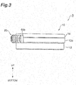
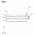
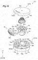
- FIG. 1 A configuration of an applicator A in accordance with a first embodiment is described with reference to Figures 1 to 10 .
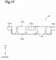
- the term “top” corresponds to the upper direction of Figures 1, 2 to 4 , 7 to 10 , 13, and 17 to 19
- the term “bottom” corresponds to the lower direction of Figures 1, 2 to 4 , 7 to 10 , 13, and 17 to 19 . That is, the top-bottom direction corresponds to the height direction of the applicator A.
- the applicator A is a device for transferring active ingredients of a medical agent or the like into the body of an animal such as a human through skin of the animal by a puncture in the skin with microneedles 32 (to be described later in detail).
- the applicator A includes a casing 10, a piston plate 20, a microneedle array 30, a conical coil spring 40, and a release member 50.
- the casing 10 includes a main body part 12 having the central axis that extends along the top-bottom direction and having a cylindrical shape, and a cover part 14 arranged on the upper end side of the main body part 12.
- the casing 10 has strength high enough to maintain the biasing force of the conical coil spring 40 (to be described later in detail).
- the material of the casing 10 include polycarbonate resin, ABS resin, and synthetic or natural resin materials such as polystyrene, polypropylene, and polyacetal (POM), and can also include silicon, silicon dioxide, ceramics, and metal (such as stainless steel, titanium, nickel, molybdenum, chromium, and cobalt). Glass fiber, carbon fiber, and the like may be added to the above-mentioned resin materials for the purpose of increasing the strength and the like.
- the applicator A has a shape that enables easy hold and enables easy application (easy puncture) of the microneedles, 32 (to be described later) to the skin of the animal (including a human).
- the outer shape of the main body part 12 may be other than the cylindrical shape, and may be, for example, multangular or rounded.
- a recess or a step may be provided on the surface of the main body part 12.
- a fine groove may be formed on the surface of the main body part 12, or a non-slippery coating layer may be provided thereon, whereby the surface of the main body part 12 may be roughened.
- a through-hole may be formed in the main body part 12 for the purpose of reducing the air resistance and the weight.
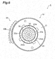
- the main body part 12 includes: an outer wall 12a having a cylindrical shape; interior inner walls 12b 1 to 12b 4 each having a circular arc-like shape; exterior inner walls 12c 1 to 12c 4 each having a circular arc-like shape; and a bottom wall 12d having a circular ring-like shape.
- a flange member 12e having a circular ring-like shape is provided at a position closer to the upper end (closer to the cover part 14) on the outer circumferential surface of the outer wall 12a.
- the flange member 12e protrudes outward from the outer circumferential surface of the outer wall 12a.
- a cutout part 12f that extends in the circumferential direction is provided between the upper end of the outer wall 12a and the flange member 12e.
- the interior inner walls 12b 1 to 12b 4 are located on the inner side of the outer wall 12a and on a circumference having the same radius.
- the interior inner walls 12b 1 to 12b 4 are arranged in the stated order in the clockwise direction when viewed from the upper end side (the cover part 14 side) of the main body part 12 at predetermined intervals in the circumferential direction.
- the interior inner wall 12b 1 and the interior inner wall 12b 2 are spaced apart from each other at a predetermined interval in the circumferential direction
- the interior inner wall 12b 2 and the interior inner wall 12b 3 are spaced apart from each other at a predetermined interval in the circumferential direction
- the interior inner wall 12b 3 and the interior inner wall 12b 4 are spaced apart from each other at a predetermined interval in the circumferential direction
- the interior inner wall 12b 4 and the interior inner wall 12b 1 are spaced apart from each other at a predetermined interval in the circumferential direction.
- the circle formed by the interior inner walls 12b 1 to 12b 4 can be set to be equivalent to or slightly larger than the outer diameter of a main body 20a (to be described later) of the piston plate 20.
- a diameter of the circle formed by the interior inner walls 12b 1 to 12b 4 on a lower side (bottom wall 12d side) may be less than that on an upper side (cover part 14 side), or may be set to gradually decrease toward the lower side in the top-bottom direction (a center axial direction of the main body part 12). In this case, when the piston plate 20 moves from the upper side toward the lower side, posture of the piston plate 20 can be easily maintained.
- An interval between the interior inner walls adjacent to each other in the circumferential direction among the interior inner walls 12b 1 to 12b 4 can be set to be equivalent to or slightly larger than width of protrusions 20c 1 to 20c 4 (to be described later) of the piston plate 20.
- the central axis of the interior inner walls 12b 1 to 12b 4 is substantially coincident with the central axis of the outer wall 12a (main body part 12), but does not need to be coincident therewith.
- the interior inner wall 12b 1 includes: a first portion 12b 11 having the upper end whose position is equivalent to the position of the upper end of the outer wall 12a; and a second portion 12b 12 having the upper end whose position is closer to the bottom wall 12d than the first portion 12b 11 , in the top-bottom direction (the central axis direction of the main body part 12). That is, the first portion 12b 11 and the second portion 12b 12 form a step in the circumferential direction.
- the interior inner wall 12b 1 and the outer wall 12a are coupled to each other by a coupling wall 12g 1 , whereby the rigidities of the two walls are enhanced.
- the position of the upper end of the coupling wall 12g 1 is equivalent to the position of the upper end of the first portion 12b 11 .
- the interior inner wall 12b 1 , the outer wall 12a, and the coupling wall 12g 1 can be integrally shaped.
- a portion of the upper end of the interior inner wall 12b 2 is cut out, the portion being closer to the interior inner wall 12b 1 .
- a portion of the upper end of the interior inner wall 12b 3 is cut out, the portion being closer to the interior inner wall 12b 2 .
- a portion of the upper end of the interior inner wall 12b 4 is cut out, the portion being closer to the interior inner wall 12b 3 .
- Structure of the interior inner walls 12b 2 to 12b 4 is the same as that of the interior inner wall 12b 1 .
- the interior inner wall 12b 2 includes first and second portions 12b 21 and 12b 22 .
- the interior inner wall 12b 3 includes first and second portions 12b 31 and 12b 32 .
- the interior inner wall 12b 4 includes first and second portions 12b 41 and 12b 42 .
- coupling walls 12g 2 to 12g 4 couple the interior inner walls 12b 2 to 12b 4 to the outer wall 12a, respectively.
- the exterior inner walls 12c 1 to 12c 4 are located between the outer wall 12a and the interior inner walls 12b 1 to 12b 4 and on a circumference having the same radius.
- the difference between the radius of the circle formed by the exterior inner walls 12c 1 to 12c 4 and the radius of the circle formed by the interior inner walls 12b 1 to 12b 4 , that is, the depths of groove parts G1 to G4 (to be described later) can be set to be equivalent to or slightly larger than the protruding lengths of the protrusions 20c 1 to 20c 4 (to be described later) of the piston plate 20.
- the exterior inner walls 12c 1 to 12c 4 are arranged in the stated order in the clockwise direction when viewed from the upper end side (the cover part 14 side) thereof at predetermined intervals in the circumferential direction. That is, the exterior inner wall 12c 1 and the exterior inner wall 12c 2 are spaced apart from each other at a predetermined interval in the circumferential direction, the exterior inner wall 12c 2 and the exterior inner wall 12c 3 are spaced apart from each other at a predetermined interval in the circumferential direction, the exterior inner wall 12c 3 and the exterior inner wall 12c 4 are spaced apart from each other at a predetermined interval in the circumferential direction, and the exterior inner wall 12c 4 and the exterior inner wall 12c 1 are spaced apart from each other at a predetermined interval in the circumferential direction.
- a lateral part of the exterior inner wall 12c 1 is connected to lateral parts of the interior inner walls 12b 1 and 12b 2 .
- the exterior inner wall 12c 1 and the interior inner walls 12b 1 and 12b 2 can be integrally shaped.
- the exterior inner wall 12c 1 and the interior inner walls 12b 1 and 12b 2 form the groove part G1 that extends in the top-bottom direction, on the inner circumferential surface of the main body part 12. That is, the groove part G1 is adjacent to the second portion 12b 22 of the interior inner wall 12b 2 .
- the position of the upper end of the exterior inner wall 12c 1 is equivalent to the position of the upper end of the outer wall 12a, in the top-bottom direction.
- the exterior inner wall 12c 1 and the outer wall 12a are coupled to each other by a coupling wall 12g 5 , whereby the rigidities of the two walls are enhanced.
- the position of the upper end of the coupling wall 12g 5 is equivalent to the position of the upper end of the exterior inner wall 12c 1 .
- the exterior inner wall 12c 1 , the outer wall 12a, and the coupling wall 12g 5 can be integrally shaped.
- the exterior inner walls 12c 2 to 12c 4 each also have the almost same structure as that of the exterior inner wall 12c 1 .
- the exterior inner wall 12c 2 and the interior inner walls 12b 2 and 12b 3 form the groove part G2 that extends in the top-bottom direction, on the inner circumferential surface of the main body part 12.
- the exterior inner wall 12c 3 and the interior inner walls 12b 3 and 12b 4 form the groove part G3 that extends in the top-bottom direction, on the inner circumferential surface of the main body part 12.
- the exterior inner wall 12c 3 and the interior inner walls 12b 3 and 12b 4 form the groove part G3 that extends in the top-bottom direction, on the inner circumferential surface of the main body part 12.
- the groove part G2 is adjacent to the second portion 12b 32 of the interior inner wall 12b 3 .
- the groove part G3 is adjacent to the second portion 12b 42 of the interior inner wall 12b 4 .
- the groove part G4 is adjacent to the second portion 12b 12 of the interior inner wall 12b 1 .
- a position of an upper end of each of the exterior inner walls 12c 3 and 12c 4 is different from that of the exterior inner wall 12c 1 .
- the position of the upper end of the exterior inner wall 12c 3 is equivalent to the position of the upper end of the adjacent second portion 12b 42 of the interior inner wall 12b 4 , in the top-bottom direction. That is, the upper end of the exterior inner wall 12c 3 is located closer to the bottom wall 12d than the upper end of the outer wall 12a.
- the position of the upper end of the exterior inner wall 12c 4 is also equivalent to the position of the upper end of the exterior inner wall 12c 3 .
- the coupling walls 12g 6 to 12g 8 couple the exterior inner walls 12c 2 to 12b 4 to the outer wall 12a, respectively.
- a position of an upper end of the coupling wall 12g 7 is different from that of the coupling wall 12g 5 .
- the position of the upper end of the coupling wall 12g 7 is located closer to the bottom wall 12d than the position of the upper end of the exterior inner wall 12c 3 . Accordingly, in a cross section of the exterior inner wall 12c 3 , the coupling wall 12g 7 , and the outer wall 12a, a portion of the coupling wall 12g 7 is observed as a recessed part.
- the bottom wall 12d is connected to a lower end of the outer wall 12a, lower ends of the interior inner walls 12b 1 to 12b 4 , lower ends of the exterior inner walls 12c 1 to 12c 4 , and lower ends of the coupling walls 12g 1 to 12g 8 .
- the outer diameter of the bottom wall 12d is equivalent to the diameter of the outer circumference of the outer wall 12a.
- the inner diameter of the bottom wall 12d is equivalent to the diameter of the circle formed by the inner circumferential surfaces of the interior inner walls 12b 1 to 12b 4 .
- the lower ends of the groove parts G1 to G4 are closed by the bottom wall 12d (see Figures 9 and 12 ).
- the cover part 14 includes a top plate 14a having a circular shape, and a cylindrical member 14b that extends downward from the periphery of the top plate 14a.
- the height of the cylindrical member 14b can be set to be equivalent to the length from the flange member 12e to the upper end on the outer wall 12a.
- the cylindrical member 14b is provided with a cutout part 14c that extends in the circumferential direction.
- the length of the cutout part 14c can be set to the same length as that of the cutout part 12f of the outer wall 12a.
- the cover part 14 is attached to the main body part 12.
- the cover part 14 is attached to the main body part 12 in the state where the cover part 14 is positioned with respect to the main body part 12 such that the cutout part 14c of the cover part 14 and the cutout part 12f of the outer wall 12a are coincident with each other.
- the cutout parts 12f and 14c form a through-hole H (see Figure 10 ) that communicates the inside and the outside of the casing 10 with each other.
- Examples of the adoptable method of attaching the cover part 14 to the main body part 12 include: a method of adhering the cylindrical member 14b of the cover part 14 to the flange member 12e of the main body part 12 with the use of an adhesive, an adhesive sheet, and the like; a method of mechanically engaging the two parts (for example, providing an engagement claw in the cylindrical member 14b, providing an engagement hole in the flange member 12e, and fitting the engagement claw and the engagement hole to each other); a method of pressure-bonding the cover part 14 to the main body part 12 (for example, setting the diameter of the cylindrical member 14b of the cover part 14 to be smaller than the outer diameter of the main body part 12 and press-fitting the cover part 14 to the main body part 12); and a method of welding the cover part 14 to the main body part 12 (for example, heating and melting the cylindrical member 14b and the flange member 12e and then cooling and integrating the two members).
- the piston plate 20 is housed in the main body part 12, and is movable in the top-bottom direction along the central axis of the main body part 12 inside of the main body part 12.
- the material of the piston plate 20 may be the same as the material of the casing 10, and may be the same as the material (to be described later) of the microneedle array 30.
- the piston plate 20 includes the disc-like main body 20a, and a cylindrical member 20b that extends upward from the periphery of the main body 20a.
- An opening, a groove, a through-hole, or the like may be formed in the main body 20a for the purpose of reducing the air resistance and the weight of the piston plate 20.
- an elongated protrusion or the like may be provided on the upper surface (the surface on which the conical coil spring 40 is arranged) of the main body 20a for the purpose of improving the rigidity of the piston plate 20.
- the inner diameter of the cylindrical member 20b is set to be larger than a maximum diameter D1 (to be described later) of the conical coil spring 40.
- the height of the cylindrical member 20b is not particularly limited as long as the cylindrical member 20b can function as such a stopper that prevents the conical coil spring 40 from dropping off the piston plate 20 during its movement in the radial direction.
- the height of the cylindrical member 20b can be set to be equivalent to the thickness of a metal wire that forms the conical coil spring 40.
- the piston plate 20 does not need to include the cylindrical member 20b.
- the function as the stopper for the conical coil spring 40 can be fulfilled by the ring-like groove.
- a failure in positioning of the conical coil spring 40 with respect to the piston plate 20 can be prevented at the time of arranging the conical coil spring 40 on the upper surface of the piston plate 20 and then attaching the cover part 14 to the main body part 12 to thereby make the applicator A.
- the plurality of protrusions (in the present embodiment, four protrusions) 20c 1 to 20c 4 are provided in the periphery (on the outer circumferential surface) of the piston plate 20, and the protrusions 20c 1 to 20c 4 each protrude outward in the radial direction (the direction that intersects with the thickness direction of the piston plate).
- the protrusions 20c 1 to 20c 4 are arranged in the stated order in the clockwise direction when viewed from above (the upper surface side of the piston plate 20 on which the conical coil spring 40 is placed) at predetermined intervals in the circumferential direction.
- the protrusions 20c 1 to 20c 4 each have a quadrangular prism shape.
- the protrusions 20c 1 to 20c 4 may have other shapes (for example, a columnar shape, a polygonal prism shape, a deformed pillar shape, a circular cone shape, a polygonal pyramid shape, a truncated circular cone shape, and a truncated polygonal pyramid shape) as long as locking with the second portions 12b 12 to 12b 42 of the interior inner walls 12b 1 to 12b 4 is possible and movement in the groove parts G1 to G4 is possible.
- shapes for example, a columnar shape, a polygonal prism shape, a deformed pillar shape, a circular cone shape, a polygonal pyramid shape, a truncated circular cone shape, and a truncated polygonal pyramid shape
- the protrusions 20c 1 to 20c 4 are movable inside the groove parts G1 to G4, respectively, along extending direction of the groove parts.
- the piston plate 20 can be guided in the top-bottom direction along the extending directions of the groove parts G1 to G4 (the axial direction of the main body part 12).
- the protrusions 20c 1 to 20c 4 are movable above the second portions 12b 22 , 12b 32 , 12b 42 , and 12b 12 , respectively, in the horizontal direction.
- the protrusions 20c 1 to 20c 4 can be placed on the upper ends of the second portion 12b 22 , 12b 32 , 12b 42 , and 12b 12 , adjacent to the groove parts G1 to G4, respectively.
- the upper ends of the second portions 12b 12 to 12b 42 of the interior inner walls 12b 1 to 12b 4 may extend in the circumferential direction so as to be parallel to a horizontal plane, and may be inclined to the horizontal plane, in the circumferential direction.
- the upper ends of the second portions 12b 12 to 12b 42 may be inclined such that the heights thereof become larger toward the respective adjacent groove parts G1 to G4.
- the protrusions 20c 1 to 20c 4 placed on the upper ends of the second portions 12b 12 to 12b 42 move toward the groove parts G1 to G4
- the protrusions 20c 1 to 20c 4 need to climb the slopes of the upper ends of the second portions 12b 12 to 12b 42 , respectively.
- the protrusions 20c 1 to 20c 4 can be prevented from unintentionally moving into the groove parts G1 to G4.
- a plurality of ribs 24 extending in the top-bottom direction is provided in the periphery (outer circumferential surface) of the piston plate 20.
- the rib 24 is formed in the shape of a semicircular column, or a shape corresponding to one of two pieces formed by dividing a column into the two pieces in a plane along its central axis. In the present embodiment, a diameter of the rib 24 decreases downward.
- the plurality of ribs 24 are arranged around the piston plate 20 at predetermined intervals, and thus when the piston plate 20 moves from an upper side toward a lower side, posture of the piston plate 20 is maintained almost horizontally, as well as the piston plate 20 slides (falls) almost straightly in the main body part 12 along the central axis of the main body part 12. Accordingly, the piston plate 20 can be guided more reliably.
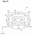
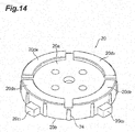
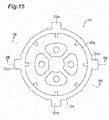
- a plurality of protrusion parts (the second protrusion parts that are four protrusion parts in the present embodiment) 20d 1 to 20d 4 extending downward from the periphery of the main body 20a is provided on the lower surface (the surface opposite to the upper surface) of the main body 20a.
- the protrusion parts 20d 1 to 20d 4 each have a circular arc-like shape when viewed from below, and are located on a circumference having the same radius.
- the protrusion parts 20d 1 to 20d 4 are arranged in the stated order in the counterclockwise direction when viewed from below at predetermined intervals in the circumferential direction.
- the protrusion part 20d 1 and the protrusion part 20d 2 are spaced apart from each other at a predetermined interval in the circumferential direction
- the protrusion part 20d 2 and the protrusion part 20d 3 are spaced apart from each other at a predetermined interval in the circumferential direction
- the protrusion part 20d 3 and the protrusion part 20d 4 are spaced apart from each other at a predetermined interval in the circumferential direction
- the protrusion part 20d 4 and the protrusion part 20d 1 are spaced apart from each other at a predetermined interval in the circumferential direction.
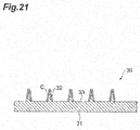
- the microneedle array 30 includes a disc-like substrate 31, a disk-like protrusion part (first protrusion part) 33 provided on one main surface (lower surface) of the substrate 31, and a plurality of microneedles 32 provided in a protruding manner on a surface of the protrusion part 33.
- the substrate 31 is a foundation for supporting the protrusion part 33.
- An outer diameter of the substrate 31 can be set to be equivalent to or slightly smaller than an inner diameter of a circle formed by the protrusion parts 20d 1 to 20d 4 .
- the microneedle array 30 can be arranged inside the protrusion parts 20d 1 to 20d 4 .
- the outer diameter of the substrate 31 can be set to be larger than an outer diameter of the protrusion part 33.
- a central axis of the substrate 31 is substantially coincident with a central axis of the protrusion part 33, but does not necessarily need to be coincident therewith. Accordingly, the substrate 31 protrudes outward from the protrusion part 33 in a radial direction of the substrate 31.
- the substrate 31 has the other main surface (upper surface) attached to the lower surface of the main body 20a of the piston plate 20(see Figure 9 ). That is, the microneedle array 30 is integrated with the piston plate 20.
- the adoptable method of attaching the substrate 31 to the piston plate 20 include: a method of mechanically integrating the substrate 31 with the piston plate 20; and a method of adhering the substrate 31 to the piston plate 20 with the use of an adhesive, an adhesive sheet, and the like.
- the microneedle array 30 and the piston plate 20 adhere to each other with an adhesive sheet 34.
- the surface of the protrusion part 33 (surface for mounting microneedles) is located outward (downward) surfaces of the protrusion parts 20d 1 to 20d 4 .
- the substrate 31 protrudes outward (downward) from the protrusion part 33 in the radial direction, and thus the protrusion part 33 and the protrusion parts 20d 1 to 20d 4 are spaced apart from each other in the state where the microneedle array 30 is attached to the piston plate 20.
- a portion between the protrusion part 33 and the protrusion parts 20d 1 to 20d 4 forms a recessed part 35 recessed from surfaces of the protrusion parts 20d 1 to 20d 4 and the protrusion part 33.
- the "microneedle region (where the microneedles are located)" in the present specification is a part of the piston plate, as well as is a region in the piston plate where the microneedles are directly or indirectly arranged.
- the microneedles 32 are not directly provided in the lower surface of the main body 20a, but the microneedle array 30 including the microneedles 32 is attached to the lower surface of the main body 20a of the piston plate 20.
- the microneedle region in the present embodiment is a region where the microneedles 32 are indirectly arranged in the piston plate 20.
- the microneedles 32 are arranged at substantially regular intervals in a zigzag (alternate) pattern on the surface of the substrate 31.
- Each microneedle 32 is a tapered structure that becomes thinner toward its leading end part from its base end part connected to the protrusion part 33.
- coating C with active ingredients may be applied to the substrate 31, the protrusion part 33, and/or the microneedles 32.
- the coating C is obtained by firmly fixing a coating agent (coating liquid) containing active ingredients and purified water and/or coating carriers to the entirety or a part of the surface of each of the substrate 31, the protrusion part 33, and/or the microneedles 32. That is, the coating C is integrated with the microneedles 32.
- extent of integration can be appropriately set, for example, the coating C can flow in a surface of each of the microneedles 32, or the coating C can be solidified to the extent that the coating C itself serves as a needle.
- the "firmly fixing” here refers to maintaining the state where the coating liquid substantially uniformly adheres to a target. Immediately after the coating, the coating liquid is firmly fixed in a dried state according to a known drying method such as air drying, vacuum drying, freeze drying, and combinations thereof.
- the active ingredients used in the present embodiment are not particularly limited, and are selected from the group consisting of antioxidants, free radical scavengers, moisturizers, depigmentation agents, fat regulating agents, UV reflective agents, humectants, antibacterial agents, antiallergic drugs, anti-acne agents, anti-aging agents, anti-wrinkling agents, bactericides, analgesics, antitussives, antipruritics, local anesthetics, anti-hair loss agents, hair growth promoting agents, hair growth inhibitor agents, dandruff inhibitors, antihistamines, keratolytic agents, anti-inflammatory agents, anti-infectives, antiemetics, anticholinergics, vasoconstrictors, vasodilators, wound healing promoters, peptides, polypeptides, proteins, deodorants, antiperspirants, skin emollients, tanning agents, skin lightening agents, antifungals, hemorrhoidal preparations, make-up preparation
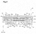
- the conical coil spring 40 is housed in the main body part 12. Specifically, the conical coil spring 40 is arranged between the piston plate 20 and the cover part 14, and is sandwiched between the upper surface of the piston plate 20 and the lower surface of the cover part 14. As shown in Figures 9 , 10 , and 22 , the conical coil spring 40 is formed by winding a metal wire having a circular shape in cross section in a spiral manner, and the conical coil spring 40 has a circular cone shape when viewed from its lateral. In the present embodiment, the conical coil spring 40 does not overlap when viewed in the central line direction of the conical coil spring 40. Examples of the metal wire include a stainless steel wire, a piano wire (iron wire), and a copper wire. Among these wires, particularly the stainless steel wire is extremely resistant to corrosion.
- the smaller diameter side of the conical coil spring 40 is in contact with the cover part 14, and the larger diameter side of the conical coil spring 40 is in contact with the piston plate 20.
- Parameters concerning the energy of the piston plate 20 actuated by the biasing force of the conical coil spring 40 include: the modulus of transverse elasticity; the wire diameter (d in Figure 22 ); the maximum diameter (D1 in Figure 22 ); the minimum diameter (D2 in Figure 22 ); the total number of coil turns; the weight of the conical coil spring 40; the total weight of the piston plate 20 and the microneedle array 30; the free height (h in Figure 22 ); the height in a close contact state; the pitch angle; and the pitch.
- the release member 50 includes: an interior part 50a located inside of the main body part 12; an exterior part 50b located outside of the main body part 12; and a coupling part 50c that couples the interior part 50a and the exterior part 50b to each other.
- the interior part 50a is a flat plate having a circular arc-like shape.
- the diameter of the interior part 50a is larger than the diameter of the interior inner walls 12b 1 to 12b 4 , and is smaller than the diameter of the outer wall 12a.
- the interior part 50a is located between the outer wall 12a and the interior inner walls 12b 1 , to 12b 4 (see Figure 11 ).
- the interior part 50a is placed above the exterior inner walls 12c 3 and 12c 4 each having a small height and the coupling walls 12g 3 , 12g 4 , 12g 7 , and 12g 8 each having a small height (see Figure 11 ).
- the interior part 50a is integrally provided with a protrusion part 50d that protrudes in the radial direction from the inner edge of the interior part 50a toward the central axis.
- the protrusion part 50d is a flat plate having a rectangular shape.
- the protrusion part 50d is located on the circumference having the same radius as that of the interior inner walls 12b 1 to 12b 4 and between the first portion 12b 31 of the interior inner wall 12b 3 and the first portion 12b 41 of the interior inner wall 12b 4 (see Figure 11 ).
- the interior part 50a is integrally provided with an elongated protrusion 50e that protrudes downward from the lower surface of the interior part 50a.
- the elongated protrusion 50e has a circular arc-like shape with a curvature equivalent to that of the interior part 50a, and extends along the interior part 50a.
- the elongated protrusion 50e is located between the exterior inner wall 12c 3 and the outer wall 12a.
- the height of the elongated protrusion 50e be set to be smaller than the depth of a recessed part formed by the exterior inner wall 12c 3 , the coupling wall 12g 7 , and the outer wall 12a.
- the exterior part 50b is a curved plate that extends in the circumferential direction along the outer circumferential surface of the main body part 12, and has a circular arc-like shape in cross section.
- a plurality of elongated protrusions that extend along the top-bottom direction are provided on the outer surface of the exterior part 50b.
- the plurality of elongated protrusions are arranged side by side along the circumferential direction.
- the outer circumferential surface of the exterior part 50b has irregularities in the circumferential direction.
- the outer circumferential surface of the exterior part 50b may be embossed or roughened instead of providing the plurality of elongated protrusions.
- the outer circumferential surface of the exterior part 50b does not particularly need to be processed.
- the coupling part 50c is a flat plate having a rectangular shape.
- the coupling part 50c protrudes in the radial direction from the outer edge of the interior part 50a toward the opposite side to the central axis.
- the coupling part 50c is exposed on the outer circumferential surface of the main body part 12 through the through-hole H.
- the width of the coupling part 50c is set to be smaller than the opening width of the through-hole H.
- the method of manufacturing the applicator A is described. First, the respective components (the casing 10, the piston plate 20, the microneedle array 30, the conical coil spring 40, and the release member 50) of the applicator A described above are prepared. The coating C is applied in advance to the microneedles 32 of the prepared microneedle array 30. Next, the microneedle array 30 is attached to the lower surface of the piston plate 20.
- the interior part 50a of the release member 50 is placed above the exterior inner walls 12c 3 and 12c 4 and the coupling walls 12g 3 , 12g 4 , 12g 7 , and 12g 8 such that the protrusion part 50d of the release member 50 is located above the first portion 12b 41 of the interior inner wall 12b 4 (see Figure 11 ). Accordingly, the release member 50 (coupling part 50c) is located on one end side of the through-hole H.
- the piston plate 20 is placed in the main body part 12 such that: the protrusion 20c 1 of the piston plate 20 is located above the second portion 12b 22 of the interior inner wall 12b 2 ; the protrusion 20c 2 of the piston plate 20 is located above the second portion 12b 32 of the interior inner wall 12b 3 ; the protrusion 20c 3 of the piston plate 20 is located above the second portion 12b 42 of the interior inner wall 12b 4 and between the protrusion part 50d of the release member 50 and the groove part G3; and the protrusion 20c 4 of the piston plate 20 is located above the second portion 12b 12 of the interior inner wall 12b 1 (see Figure 11 ).
- the protrusion part 50d of the release member 50 and the protrusion 20c 4 of the piston plate 20 are placed above the second portion 12b 42 of the interior inner wall 12b 4 , and hence it is preferable that the width of the second portion 12b 42 be larger than the sum of the width of the protrusion part 50d and the width of the protrusion 20c 4 .
- the conical coil spring 40 is placed on the upper surface of the piston plate 20 such that: the larger diameter side of the conical coil spring 40 faces downward; and the smaller diameter side thereof faces upward. In this way, the conical coil spring 40 stably stands up at the time of placing the conical coil spring 40 on the piston plate 20, and hence the applicator A1 can be manufactured more easily.
- the cover part 14 is attached to the main body part 12 such that the cutout part 12f of the main body part 12 and the cutout part 14c of the cover part 14 coincide with each other.
- the protrusions 20c 1 to 20c 4 are placed on the second portions 12b 12 to 12b 42 of the interior inner walls 12b 1 to 12b 4 , respectively, even if the conical coil spring 40 is compressed by attaching the cover part 14 to the main body part 12, the piston plate 20 is not pushed out in the bottom direction by the conical coil spring 40. That is, the piston plate 20 is locked with the casing 10 (main body part 12).
- the piston plate 20 is held at its retraction position on the cover part 14 side inside of the main body part 12, in the state where the cover part 14 and the piston plate 20 compress the conical coil spring 40.
- locked state Such a state as described above where the piston plate 20 is locked with the casing 10 (main body part 12) and where the cover part 14 and the piston plate 20 compress the conical coil spring 40 is hereinafter referred to as "locked state”.
- Locking the piston plate 20 with the casing 10 (main body part 12) at its retraction position as described above is also referred to as cocking.
- the metal wire that forms the conical coil spring 40 does not overlap when viewed in the central line direction of the conical coil spring 40, and hence the height of the conical coil spring 40 sandwiched between the piston plate 20 and the cover part 14 becomes equivalent to the wire diameter, in the state where the piston plate 20 is locked (cocked) with the casing 10 (see Figure 9 ).
- the conical coil spring 40 remains in a compressed state until the applicator A is used by a user after manufacture and shipping thereof.
- the applicator A is positioned with respect to a portion of skin to which a medical agent or the like is desired to be applied, such that the microneedles 32 face the skin.
- the release member 50 is slid to another end side of the through-hole H while the applicator A is kept positioned (see Figure 24 ).
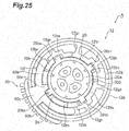
- the protrusion part 50d of the release member 50 pushes the protrusion 20c 3 of the piston plate 20 toward the groove part G3. Consequently, the piston plate 20 turns.
- the upper end of the second portion 12b 22 is adjacent to the end part on the cover part 14 side of the groove part G1 (the upper end part of the groove part G1). Hence, if the piston plate 20 turns, the protrusion 20c 1 slides on the upper end of the second portion 12b 22 to reach the groove part G1.
- the upper end of the second portion 12b 32 is adjacent to the end part on the cover part 14 side of the groove part G2 (the upper end part of the groove part G2).
- the protrusion 20c 2 slides on the upper end of the second portion 12b 32 to reach the groove part G2.
- the upper end of the second portion 12b 42 is adjacent to the end part on the cover part 14 side of the groove part G3 (the upper end part of the groove part G3).
- the protrusion 20c 3 slides on the upper end of the second portion 12b 32 to reach the groove part G3.
- the upper end of the second portion 12b 12 is adjacent to the end part on the cover part 14 side of the groove part G4 (the upper end part of the groove part G4).
- the protrusion 20c 4 slides on the upper end of the second portion 12b 12 to reach the groove part G4.
- the locking (cocking) of the piston plate 20 with the casing 10 (main body part 12) is released (see Figure 25 ).
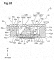
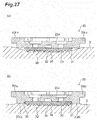
- the piston plate 20 is moved by the biasing force (elastic force) of the conical coil spring 40 outward (toward the skin) along the groove parts G1 to G4 (the central axis of the main body part 12) inside of the main body part 12, and the microneedle array 30 collides against the skin S (see Figure 26 and (a) of Figure 27 ).
- the protrusions 20c 1 to 20c 4 are brought into contact with the bottom wall 12d, and hence the piston plate 20 is prevented from jumping out of the casing 10 (main body part 12).
- the microneedles 32 When the microneedle array 30 collides against the skin S, the microneedles 32 are stuck into the skin S.
- the speed of the microneedles 32 (piston plate 20) on this occasion may be 4 m/s to 30 m/s, 4 m/s to 15 m/s, or 7 m/s to 15 m/s.
- the microneedles 32 In the configuration in which the microneedles 32 collide against the skin S at a speed of 4 m/s to 30 m/s, the microneedles 32 can be appropriately stuck into the skin S, whereby the medical agent or the like can be sufficiently transferred into the body of an animal.
- the skin S may be greatly recessed by the microneedle array 30 (see (a) of Figure 27 ). This may cause the microneedle array 30 to bounce off the skin S due to elastic force of the skin S. Then, the microneedles 32 once stuck into the skin may come off the skin S to affect transfer of the active ingredients into a body.
- the (a) of Figure 27 shows a state when the piston plate 200 without the protrusion parts 20d 1 to 20d 4 on the lower surface (the surface opposite to the upper surface) of the main body 20a collides against the skin S.
- the protrusion parts 20d 1 to 20d 4 are arranged in the periphery of the protrusion part 33 while being spaced apart from the protrusion part 33.
- the undulation is reduced by the protrusion parts 20d 1 to 20d 4 (see (b) of Figure 27 ).
- This causes the piston plate 20 not to easily bounce off the skin S, and thus the microneedles once stuck into the skin S tends to easily stay in the skin S.
- the active ingredients can be sufficiently transferred into a body.
- the (b) of Figure 27 shows a state when the piston plate 20 in accordance with the present embodiment collides against the skin S.
- a portion between the protrusion part 33 and the protrusion parts 20d 1 to 20d 4 forms a recessed part 35 recessed from surfaces of the protrusion parts 20d 1 to 20d 4 and the protrusion part 33.
- undulation (transmission of vibration) of the skin S may be absorbed in the recessed part 35. Accordingly, a bounce of the piston plate 20 from the skin S can be reduced further.
- pressing the protrusion parts 20d 1 to 20d 4 on the skin allows mechanical energy applied by the applicator A to form nodes of vibration so that a vibrating surface between the nodes absorbs vibration energy in a part of the skin surrounded by the protrusion parts 20d 1 to 20d 4 (a region of the skin corresponding to the recessed part 35 and the microneedle region).
- a user can make a puncture in skin S using the applicator A by simply sliding the release member 50. Accordingly, whoever may use the applicator A, the biasing force of the conical coil spring 40 is transmitted to the microneedles 32 with the intermediation of the piston plate 20, and the microneedles 32 are stuck into the skin S with a given impact force. Hence, the puncture in the skin S can be reliably made (the reproducibility of the puncture is enhanced).
- active ingredients of the coating C that adhere to the microneedles 32 are delivered into the body, and the active ingredients are transferred into the body through the skin S.
- the locked state where the piston plate 20 is locked with the casing 10 is released by the release member 50. Consequently, the biasing force of the conical coil spring 40 acts on the piston plate 20, and the piston plate 20 moves along the groove parts G1 to G4 inside of the main body part 12 to reach a position for action on the skin S.
- a member such as a shaft that extends in the axial direction of the main body part 12 (the height direction of the applicator A) does not need to be attached to the piston plate 20.
- the conical coil spring 40 is used to exert biasing force on the piston plate 20. When being compressed, the height of the conical coil spring 40 becomes extremely smaller compared with general cylindrical coil springs. In this way, the height of the applicator A itself can be made smaller, thereby achieving a reduction in weight of the applicator A.
- the applicator A needs to be held on the skin S for a long time after a collision of the microneedles 32 against the skin S. Even in such a case, with the use of the applicator A in accordance with the present embodiment that can achieve a reduction in size and weight, the user can put on clothing and move without any restriction with the applicator A being attached to the skin S. Moreover, because the applicator A in accordance with the present embodiment is small, even in the case where the user freely moves in such a manner, the applicator A is extremely unlikely to collide against another object (obstacle) to thereby cause the microneedles 32 to come off the skin S or to break and stay in the skin S.
- obstacle another object
- the user may have trouble handling it or feel fear due to the large appearance thereof.
- the applicator A in accordance with the present embodiment that can achieve a reduction in size and weight can be easily handled, and a feeling of fear that the user may develop can be significantly reduced.
- the release member 50 is located lateral to (on the outer circumferential surface of) the casing 10 (main body part 12), and hence the release member 50 is suppressed from extending in the axial direction of the main body part 12 (the height direction of the applicator A).
- the height of the applicator A itself can be made further smaller.
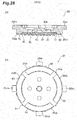
- an adhesive substance 60 with adhesive capability may be provided in at least a part of a surface of each of the protrusion parts 20d 1 to 20d 4 .
- the adhesive substance 60 for example, includes acrylic, synthetic rubber, and silicon.
- Figure 28 shows a state where the adhesive substance 60 is provided over the entire surface of each of the protrusion parts 20d 1 to 20d 4 .
- the (a) of Figure 28 shows a cross section of the piston plate 20, and the (b) of Figure 28 shows a bottom surface of the piston plate 20.
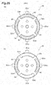
- Figure 29 shows a state where the adhesive substance 60 is provided in a part of the surfaces of the protrusion parts 20d 1 to 20d 4 .
- the (a) of Figure 29 shows, for each of the protrusion parts 20d 1 to 20d 4 , a state where the adhesive substance 60 is provided in a part of the surface of the protrusion parts 20d 1 to 20d 4 .
- the (b) of Figure 29 shows a state where the adhesive substance 60 is provided in a part of the surface of at least one of the protrusion parts 20d 1 to 20d 4 (the protrusion parts 20d 1 and 20d 3 in (b) of Figure 29 ).
- Providing the adhesive substance 60 in the piston plate 20 as described above allows the adhesive substance 60 to tend to adhere to the skin when the piston plate 20 collides against the skin S. Accordingly, a bounce of the piston plate 20 from the skin S can be reduced more.
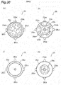
- the piston plate 20 may include at least one protrusion part as shown in Figure 30 .
- the (a) of Figure 30 shows a state where two protrusion parts 20d 5 and 20d 6 each having a circular arc-like shape are provided in the lower surface (the surface opposite to the upper surface) of the main body 20a. These protrusion parts 20d 5 and 20d 6 face each other and are located on a circumference having the same radius.
- the (b) of Figure 30 shows a state where two through-holes 20e are formed in each of the protrusion parts 20d 1 to 20d 4 .
- Each of (c) and (d) of Figure 30 shows a state where one protrusion part 20d having an annular shape is provided in the lower surface (the surface opposite to the upper surface) of the main body 20a.
- a width of the protrusion part 20d shown in (d) of Figure 30 is set to be more than a width of the protrusion part shown in (c) of Figure 30 .
- FIG. 31 Still another form of the piston plate 20 is shown in Figure 31 .
- the (a) of Figure 31 shows the piston plate 20 in which a plurality of protrusion parts (six protrusion parts in (a) of Figure 31 ) 20d each having a columnar shape are arranged in the lower surface of the main body 20a so as to surround the microneedle array 30 at predetermined intervals.
- the (b) and (c) of Figure 31 show states where outlines of the piston plate 20 having a quadrangular shape and a triangular shape, respectively.
- the outline of the piston plate 20 is not limited to a circular shape, and thus can be formed in a variety of shapes other than the circular shape.
- a shape of the protrusion part 20d may correspond to the outline of the piston plate 20, or may be different from the outline of the piston plate 20.
- an outline of the microneedle array 30 may correspond to a shape of the protrusion part 20d surrounding the microneedle array 30, or may be different from the shape of the protrusion part 20d surrounding the microneedle array 30.
- Each of (d) and (e) of Figure 31 shows the piston plate 20 in which a plurality of microneedle arrays 30 can be arranged.
- the protrusion part 20d having a lattice shape is provided in the lower surface of the main body 20a of the piston plate 20, and four recessed parts in the shape of a rectangle surrounded by the main body 20a and the protrusion part 20d are formed.
- the microneedle arrays 30 are arranged in each of the recessed parts.
- the (e) of Figure 31 shows another variation of (d) of Figure 31 , in which each of recessed parts has a circular shape.
- the piston plate 20 and the microneedle array 30 are integrated with each other, however, the piston plate 20 shown in each of Figures 13 to 19 and the microneedle array 30 shown in each of Figures 20 and 21 may be separately provided.
- the microneedle array 30 is placed on the skin S, the applicator A is placed on the skin S so as to be opposed to the microneedle array 30 and then, the applicator A is actuated.
- the piston plate 20 collides against the microneedle array 30 on the skin S, and a puncture into the skin is made.
- the applicator A and the microneedle array 30 are arranged to face each other so that the protrusion parts 20d 1 to 20d 4 can surround the microneedle array 30 when the piston plate 20 collides against the microneedle array 30 on the skin S.
- the microneedle array 30 is integrated with the piston plate 20.
- the microneedles 32 may be shaped integrally with the lower surface of the piston plate 20.
- the piston plate 20 includes the protrusion parts 20d 1 to 20d 4 , and a protrusion part 21.
- the protrusion part 21 is located inside the protrusion parts 20d 1 to 20d 4 . That is, the protrusion part 21 is surrounded by the protrusion parts 20d 1 to 20d 4 .
- a surface of the protrusion part 21 is located outward from surfaces of the protrusion parts 20d 1 to 20d 4 .
- the protrusion part 21 and the protrusion parts 20d 1 to 20d 4 are spaced apart from each other.
- a portion between the protrusion part 21 and the protrusion parts 20d 1 to 20d 4 forms a recessed part 22 recessed from surfaces of the protrusion parts 20d 1 to 20d 4 and the protrusion part 33.
- the main body 20a of the piston plate 20 can be regarded as being equal to the substrate of the microneedle array. That is, the microneedle array can be regarded as behaving as the piston plate 20.
- the surface of the protrusion part 33 (surface for mounting microneedles) is located outward (downward) from the surfaces of the protrusion parts 20d 1 to 20d 4
- a positional relationship between the surface of the protrusion part 33 and the surfaces of the protrusion parts 20d 1 to 20d 4 is not limited to the above.
- the surface of the protrusion part 33 and the surfaces of the protrusion parts 20d 1 to 20d 4 may be located at a substantially same height, or the surfaces of the protrusion parts 20d 1 to 20d 4 may be located outward (downward) from the surface of the protrusion part 33.
- a leading end of each of the microneedles 32 may be located outward (downward) from the surfaces of the protrusion parts 20d 1 to 20d 4 so that the microneedles 32 are stuck into the skin S.
- the microneedles 32 are arranged at substantially regular intervals in a zigzag (alternate) pattern on the surface of the substrate 31.
- the density of the microneedles 32 on the substrate 31 may be different.
- the density of the microneedles 32 may be set to be higher in the vicinity of the center of the substrate 31 than in the periphery thereof, and may be set to be higher in the periphery of the substrate 31 than in the vicinity of the center thereof.
- the heights of the microneedles 32 may be all the same, and may be different. In the case where the heights of the microneedles 32 are different, for example, the heights of the microneedles 32 may be set to be larger in the vicinity of the center of the substrate than in the periphery thereof, and may be set to be larger in the periphery of the substrate than in the vicinity of the center thereof.
- the conical coil spring 40 is used to exert a biasing force on a piston P, but a non-linear coil spring having another shape may be used.
- the non-linear coil spring having another shape include a coil spring 42 having a drum-like shape with a narrow part (see (b) of Figure 33 ), and a coil spring 43 having a barrel-like shape (see (c) of Figure 33 ).
- a cylindrical coil spring 44 shown in (d) of Figure 33 may be used.
- the metal wire that forms the conical coil spring 40 does not overlap when viewed in the extending direction of the central line of the conical coil spring 40.
- the conical coil spring 40 formed by winding a metal wire such that the metal wire overlaps when viewed in the extending direction of the central line thereof.
- the free height h of the conical coil spring 40 can be set to be smaller than a value obtained by multiplying the wire diameter d by the total number of turns.
- the locking (cocking) of the piston plate with the casing (main body part) is released by exerting a turning force on the piston plate, or by turning the piston plate.
- the force that is exerted on the piston plate for releasing the locking of the piston plate is not limited to the turning force.
- the locking of the piston plate may be released by moving the piston plate in the horizontal direction with respect to the casing (main body part).
- the locking of the piston plate may be released by moving or turning a lock member in the horizontal direction without moving the piston plate that is locked with the casing (main body part) with the intermediation of the lock member.
- the microneedle array 30 includes the protrusion part 33 in the above-mentioned embodiments, the present invention is also applicable in the case of using a microneedle array 30A without a protrusion part shown in Figure 34 .
- the microneedle array 30A includes a disc-like substrate 31, and a plurality of microneedles 32 that are provided on a surface of the substrate 31.
- an outer diameter of the substrate 31 is set to be equivalent to or slightly smaller than an inner diameter of a circle formed by the protrusion parts 20d 1 to 20d 4 .
- the microneedle array 30A is arranged inside the protrusion parts 20d 1 to 20d 4 .
- the substrate 31 and the protrusion parts 20d 1 to 20d 4 may be spaced apart from each other to allow a portion between the surface (surface for mounting microneedles) of the substrate 31, including the microneedles 32, and the protrusion parts 20d 1 to 20d 4 to form recessed parts that are recessed from both of the surface of the substrate 31 and the surfaces of the protrusion parts 20d 1 to 20d 4 .
- the microneedle array 30A is attached to the lower surface of the main body 20a of the piston plate 20 to be integrated with the piston plate 20. Length of needles of the microneedle array 30A may be set so that leading ends of the microneedles 32 project downward from the protrusion parts 20d 1 to 20d 4 .
- the applicator to which the microneedle array 30A is attached is actuated so that when the microneedles 32 are stuck into skin, at least a part of the surface of the substrate 31, including the microneedles 32, can collide against the skin.
- the microneedles 32 are not directly provided in the lower surface of the main body 20a, but the microneedle array 30A including the microneedles 32 is attached to the lower surface of the main body 20a of the piston plate 20.
- the microneedle region in this variation is a region where the microneedles 32 are indirectly arranged in the piston plate 20.
- the microneedles may be provided on the lower surface (main surface) of the main body of the piston plate, or the piston plate itself, without preparing the microneedle array.
- the microneedle region in this variation is a region where the microneedles 32 are directly arranged on the main surface of the piston plate. Even in this variation, a portion between the microneedle region and the protrusion parts (corresponding to the protrusion parts 20d 1 to 20d 4 in the above-mentioned embodiments) may form recessed parts that are recessed from both of the microneedle region and surfaces of the protrusion parts.
- the microneedle array 30A and the piston plate 20 may be separated from each other.
- the microneedle array 30A is placed on skin, the applicator A is placed on the skin so as to be opposed to the microneedle array 30 and then, the applicator A is actuated.
- the piston plate 20 collides against the microneedle array 30A on the skin S, and a puncture into the skin S is made.
- the applicator A and the microneedle array 30A are arranged to face each other so that the protrusion parts 20d 1 to 20d 4 can surround the microneedle array 30A when the piston plate 20 collides against the microneedle array 30A on the skin S.
- microneedle array 30A is substituted for the microneedle array 30, the same effect as that of the above-mentioned embodiments can be acquired.
- a sectional shape of each of the protrusion part 20d 1 to 20d 4 taken along a radial direction of the piston plate 20 is not limited, and thus, for example, includes a rectangle, a circle, an ellipse, a semicircle, a triangle, and other polygons.
- the protrusion parts 20d 1 to 20d 4 may be formed softer than other portions in the piston plate 20, and thus, for example, the protrusion parts 20d 1 to 20d 4 may be made from material softer than that of other portions in the piston plate 20.
- the protrusion parts 20d 1 to 20d 4 may be used not only to improve puncture performance, but also to, for example, allow the protrusion parts or an assembly of the protrusion parts and another component to secure sterility of the microneedles.
- a difference in height (a difference D in height shown in Figure 36 ) between a leading end surface of the protrusion part of the piston plate and a leading end of the microneedle may be 0 mm or more than 0 mm.
- a lower limit of the difference in height for example, may be 0 mm, 0.1 mm, 0.2 mm, 0.3 mm, 0.4 mm, 0.5 mm, 0.6 mm, 0.7 mm, 0.8 mm, 0.9 mm, or 1 mm.
- An upper limit of the difference in height may be 10 mm, 9 mm, 8 mm, 7 mm, 6 mm, 5 mm, 4 mm, 3 mm, 2 mm, 1.9 mm, 1.8 mm, 1.7 mm, 1.6 mm, 1.5 mm, 1.4 mm, 1.3 mm, 1.2 mm, 1.1 mm, 1.0 mm, 0.9 mm, 0.8 mm, 0.7 mm, 0.6 mm, or 0.5 mm.
- the difference in height more than 0 mm is premised on the leading end of the microneedle that projects outward (downward) from the leading end surface of the protrusion part of the piston plate when the applicator is viewed from sides. Setting the difference in height in this way enables improving puncture performance.
- a lower limit of a value obtained by D/F which is referred to as a "value D/F" or a “D/F ratio” in the present specification, for example, may be 0.0, 0.1, 0.2, 0.3, 0.4, 0.5, 0.6, 0.7, 0.8, 0.9, or 1.0.
- An upper limit of the value D/F for example, may be 3.0, 2.9, 2.8, 2.7, 2.6, 2.5, 2.4, 2.3, 2.2, 2.1, 2.0, 1.9, 1.8, 1.7, 1.6, 1.5, 1.4, 1.3, 1.2, 1.1, or 1.0. Setting the value D/F indicating a ratio of the difference in height to the average length of the microneedles in this way enables improving puncture performance.
- Puncture performance was evaluated by using: the applicator A in accordance with the present embodiment (Example 1); an applicator in which the piston plate 20 of the applicator A is substituted for the form shown in Figure 28 (Example 2); and an applicator in which the piston plate of the applicator A is substituted for the form shown in (a) of Figure 27 (comparative example). That is, Example 1 included the piston plate 20 that had the protrusion parts 20d 1 to 20d 4 .
- Example 2 had the same structure as that of Example 1 other than that the piston plate 20 had an adhesive substance 60 in addition to the protrusion parts 20d 1 to 20d 4 .
- the comparative example had the same structure as that of Example 1 other than that the piston plate 20 did not have the protrusion parts 20d 1 to 20d 4 as well as the adhesive substance 60.
- OVA ovalbumin
- the puncture performance was evaluated on the basis of the transfer rate thus obtained.
- the transfer rate here refers to the rate of the amount of OVA delivered to the rabbit skin to the amount of OVA (coating C) firmly fixed to the microneedles 32.
- the prepared microneedle array 30 was made of polylactide.
- the area of the substrate 31 of the microneedle array 30 was 1.13 cm 2 .
- the number of the microneedles 32 of the microneedle array 30 was 640.
- the density of the microneedle 32 of the microneedle array 30 was 566 needles/cm 2 .
- the height of each microneedle 32 of the microneedle array 30 was 500 ⁇ m.
- the coating range when OVA was applied to the microneedles 32 was a range of about 180 ⁇ m including the tips of the microneedles 32.
- the initial content of OVA coating the microneedles 32 was 80 ⁇ g.
- the applicators each were placed still on the rabbit skin, and the microneedles 32 were stuck into the rabbit skin by actuating the applicators each, whereby OVA was delivered into the rabbit skin.
- the microneedle array 30 removed from the rabbit skin was immersed in phosphate buffered saline (PBS), whereby OVA was extracted.
- PBS phosphate buffered saline
- the amount of extracted OVA was subtracted from the initial content, whereby the amount of transfer was obtained.
- the transfer rate was obtained from the ratio of the amount of transfer to the initial content.
- Example 1 could achieve a high transfer rate as compared with the comparative example, and improvement in puncture performance was found.
- Example 2 could achieve a higher transfer rate as compared with Example 1, and further improvement in puncture performance was found.
- the parameters include a height A of the protrusion part, a width B of the protrusion part, a distance (width of the recessed part) C between the protrusion part and the substrate of the microneedle array, a difference D in height between the leading end surface of the protrusion part and the leading end of the microneedle, a distance E between a central axis of a microneedle located outermost and the protrusion part, and an average length F of the microneedles.
- a reference sign 20d designates one or more protrusion parts
- reference signs 30, 31, and 32 designate the microneedle array, the substrate, and the microneedle, respectively, as well as a reference sign 90 designates an adhesive layer.
- the height A is a distance between a surface of the piston plate, on which the microneedle array is placed, and a leading end surface of the protrusion part.
- the width B is a length of the protrusion part along a radial direction of the piston.
- the distance C is a length between a side surface of the protrusion part and a side surface of the substrate.
- the difference D in height is acquired by using an average value because a height of an individual microneedle is not always the completely identical.
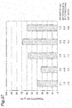
- Figure 37 is a graph showing relationships between the height A, the difference D in height, and the D/F ratio, and a transfer rate (%) of active ingredients into skin of a hairless rat, the relationships being acquired under the following conditions: the average length F of the microneedles was 0.5 mm; a thickness of the substrate was 0.7 mm; a thickness of the adhesive layer was 0.1 mm; fluorescein was used as the active ingredients; an application time of the microneedle array was five minutes; the width B was 0.7 mm; the distance C was 0.55 mm; and the distance E was 1.55 mm.
- the puncture performance tended to be improved if the height A was 0.6 mm or more (the difference D in height is 0.7 mm or less). It was also found that good puncture performance could be acquired if the difference D in height is 0 mm.
- Fluorescent light was found in region equal to or more than 50% of skin surface, and was not found in other regions. Fluorescent light was found little at shallow depths of skin, and found bright at deep depths of skin. 0.8 Fluorescent light was found in region equal to or more than 50% of skin surface, and was not found in other regions. Fluorescent light was found little at shallow depths of skin, and found bright at deep depths of skin. 1.3 Fluorescent light was found in region not less than 30% and less than 50% of skin surface, and was not found in other regions. Fluorescent light was found brighter at shallow depths of skin, and found darker at deep depths of skin.
- Figure 38 is a graph showing relationships between the height A, the difference D in height, and the D/F ratio, and a transfer rate (%) of active ingredients into human skin, the relationships being acquired under the following conditions: the average length F of the microneedles was 0.5 mm; a thickness of the substrate was 0.7 mm; a thickness of the adhesive layer was 0.1 mm; OVA and Red No. 40 were used as the active ingredients; an application time of the microneedle array was five minutes; the width B was 2.09 mm; the distance C was 0.55 mm; and the distance E was 1.55 mm. According to this verification, it was found that a correlation between the height A and the puncture performance was verified, as with Figure 37 , even if the active ingredients and an object to be administered were changed.
- Figure 39 is a graph showing relationships between the height A, the difference D in height, and the D/F ratio, and a transfer rate (%) of active ingredients into skin of a hairless rat, the relationships being acquired under the following conditions: the average length F of the microneedles was 0.5 mm; a thickness of the substrate was 0.7 mm; a thickness of the adhesive layer was 0.1 mm; fluorescein was used as the active ingredients; an application time of the microneedle array was five minutes; the width B was 2.09 mm; the distance C was 0.55 mm; and the distance E was 1.55 mm. According to this verification, it was found that a correlation between the height A and the puncture performance was verified, as with Figure 37 , even if the width B was changed.
- Fluorescent light was found in region equal to or more than 95% of skin surface, and was not found in other regions. Fluorescent light was found little at shallow depths of skin, and found bright at deep depths of skin. 0.8 Fluorescent light was found in region equal to or more than 95% of skin surface, and was not found in other regions. Fluorescent light was found little at shallow depths of skin, and found bright at deep depths of skin. 1.3 Fluorescent light was found in region less than 90% of skin surface, and was not found in other regions. Fluorescent light was found brighter at shallow depths of skin, and found darker at deep depths of skin.
- Transfer rates of active ingredients were measured under the following conditions: the average length F of the microneedles was 0.5 mm; a thickness of the substrate was 0.7 mm; a thickness of the adhesive layer was 0.1 mm; fluorescein was used as the active ingredients; the microneedle array was applied to skin of a hairless rat for five minutes; the width B was 0.7 mm; the distance C was 0.55 mm; the distance E was 1.55 mm; and the height A (and the difference D in height) was 0.1 mm (1.2 mm), and 0.6 mm (0.7 mm).
- the transfer rate was 49.4% when the height A was 0.1 mm (the difference D in height was 1.2 mm), and was 88.9% when the height A was 0.6 mm (the difference D in height was 0.7 mm).
- punctures were uneven under conditions where the height A was 0.1 mm (the difference D in height was 1.2 mm) as well as the active ingredients remained on a surface of the skin.
- punctures were uniform when the height A was 0.6 mm (the difference D in height was 0.7 mm) as well as little amount of the active ingredients remained on the surface of the skin.
- appropriate selection of the height A (or the difference D in height) improved uniformity of the punctures and the transfer rate.
- Figure 40 is a graph showing relationships between the height A, the difference D in height, and the D/F ratio, and a transfer rate (%) of active ingredients into human skin, the relationships being acquired under the following conditions: the average length F of the microneedles was 0.5 mm; a thickness of the substrate was 0.7 mm; lidocaine was used as the active ingredients; an application time of the microneedle array was five minutes; the width B was 2.09 mm; the distance C was 0.55 mm; and the distance E was 1.55 mm; the height A was set at 0.6 mm or 0.8 mm; and the difference D in height was adjusted by changing the thickness of the adhesive layer. According to this verification, it was suggested that the difference D in height was important to improve the puncture performance.
- Figure 41 is a graph showing relationships between the width B and the transfer rate (%) of active ingredients into skin of a hairless rat, the relationships being acquired under the following conditions: the average length F of the microneedles was 0.5 mm; a thickness of the substrate was 0.7 mm; a thickness of the adhesive layer was 0.1 mm; fluorescein was used as the active ingredients; an application time of the microneedle array was five minutes; the height A was 0.6 mm; the distance C was 0.55 mm; the difference D in height was 0.7 mm; the distance E was 1.55 mm; and the width B was set at 2.09 mm and 0.7 mm. According to this verification, it was found that the width B did not affect the puncture performance.
- Figure 42 is a graph showing relationships between the distance C and the transfer rate (%) of active ingredients into skin of a hairless rat, the relationships being acquired under the following conditions: the average length F of the microneedles was 0.5 mm; a thickness of the substrate was 0.7 mm; a thickness of the adhesive layer was 0.1 mm; fluorescein was used as the active ingredients; an application time of the microneedle array was five minutes; the height A was 0.6 mm; the width B was 0.7 mm; the difference D in height was 0.7 mm; the distance C was set at 0.55 mm and 1.94 mm; and the distance E was set at 1.55 mm and 2.94 mm. According to this verification, it was found that the distance C did not affect the puncture performance. In addition, a distance between a sidewall of the casing and the protrusion part (a sum of this distance and the distance C is constant because the width B is fixed) also did not affect the puncture performance.
- the present invention can be defined as follows.
Landscapes
- Health & Medical Sciences (AREA)
- Engineering & Computer Science (AREA)
- Dermatology (AREA)
- Medical Informatics (AREA)
- Anesthesiology (AREA)
- Biomedical Technology (AREA)
- Heart & Thoracic Surgery (AREA)
- Hematology (AREA)
- Life Sciences & Earth Sciences (AREA)
- Animal Behavior & Ethology (AREA)
- General Health & Medical Sciences (AREA)
- Public Health (AREA)
- Veterinary Medicine (AREA)
- Media Introduction/Drainage Providing Device (AREA)
Abstract
Description
- One aspect of the present invention relates to an applicator for transferring active ingredients into a body through skin by a puncture in the skin.
- Up to now, an applicator that holds a microneedle array by means of a latch mechanism or the like has been known, the microneedle array including a large number of microneedles each having a leading end to which a medical agent or the like is applied (see
Patent Literatures 1 to 5). If the microneedle array held by the applicator is caused to collide against skin by disengaging the latch mechanism, the microneedles are stuck into the skin, and active ingredients contained in the medical agent or the like are transferred into the body of an animal (for example, a human) through the skin. -
- Patent Literature 1: Japanese Patent No.
4659332 - Patent Literature 2: Japanese Unexamined Patent Publication No.
2007-516781 - Patent Literature 3: International Publication No.
WO 2009/107806 - Patent Literature 4: International Publication No.
WO 00/009184 - Patent Literature 5:
U.S. Patent Application Publication 2011/276027 - Unfortunately, when the microneedle array collides against skin by opening the latch mechanism, elastic force of the skin may cause the microneedle array to bounce off the skin. In that case, the microneedles once stuck into the skin may come off the skin to affect transfer of the active ingredients into a body.
- Thus, it is an object of one aspect of the present invention to provide an applicator capable of sufficiently transferring active ingredients into a body.
- An applicator in accordance with one aspect of the present invention is configured to transfer an active ingredient into a body through skin by a puncture in the skin with microneedles. The applicator comprises a piston plate that is provided on its one main surface with a first protrusion part and at least one second protrusion part. The first protrusion part is provided on its surface with microneedles, and the second protrusion part is provided in a periphery of the first protrusion part while spaced apart from the first protrusion part.
- In the applicator in accordance with one aspect of the present invention, the at least one second protrusion part is provided in the periphery of the first protrusion part while spaced apart from the first protrusion part. Thus, even if the first protrusion part collides against skin to cause the skin to undulate (even if undulation is produced in the skin), the undulation is reduced by the second protrusion part. This causes the piston plate not to easily bounce off the skin, and thus the microneedles once stuck into the skin tend to easily stay in the skin. As a result, the active ingredients can be sufficiently transferred into a body.
- In the second protrusion part, an adhesive substance with adhesive capability may be provided in at least a part of a surface thereof. In this case, the adhesive substance tends to adhere to the skin when the piston plate collides against the skin. Accordingly, a bounce of the piston plate from the skin can be reduced more.
- A plurality of the second protrusion parts may be provided on the piston plate, the plurality of the second protrusion parts being disposed in such a way as to surround the first protrusion part.
- The second protrusion part may have an annular shape surrounding the entire periphery of the first protrusion part.
- A portion between the first protrusion part and the second protrusion part may form a recessed part recessed from surfaces of the protrusion parts. In this case, undulation of the skin may be absorbed in the recessed part. Accordingly, a bounce of the piston plate from the skin can be reduced further.
- An applicator in accordance with another aspect of the present invention is configured to transfer an active ingredient into a body through skin by a puncture in the skin with microneedles. The applicator comprises a piston plate that transmits impact force to a microneedle array in which microneedles are provided in a predetermined region when one main surface of the piston plate collides against the microneedle array. The piston plate includes at least one protrusion part that is provided in the one main surface in such a way as to surround the microneedle array while spaced apart from the predetermined region of the microneedle array.
- In the applicator in accordance with another aspect of the present invention, the at least one protrusion part is provided in the one main surface of the piston plate in such a way as to surround the microneedle array while spaced apart from the predetermined region in the microneedle array. Thus, even if the piston plate collides against the microneedle array previously arranged on the skin to cause the skin to undulate (even if undulation is produced in the skin), the undulation is reduced by the protrusion part. This causes the piston plate not to easily bounce off the skin, and thus the microneedles once stuck into the skin tends to easily stay in the skin. As a result, the active ingredients can be sufficiently transferred into a body.
- In the at least one protrusion part, an adhesive substance with adhesive capability may be provided in at least a part of a surface thereof. In this case, the adhesive substance tends to adhere to the skin when the piston plate collides against the skin. Accordingly, a bounce of the piston plate from the skin can be reduced more.
- A plurality of the second protrusion parts may be provided on the piston plate, the plurality of the protrusion parts being disposed in such a way as to surround the microneedle array.
- The protrusion part may have an annular shape surrounding the entire periphery of the microneedle array.
- A portion between the predetermined region in the microneedle array and the protrusion part forms a recessed part recessed from the predetermined region and a surface of the protrusion part. In this case, undulation of the skin may be absorbed in the recessed part. Accordingly, a bounce of the piston plate from the skin can be reduced further.
- An applicator in accordance with still another aspect of the present invention is configured to transfer an active ingredient into a body through skin by a puncture in the skin with microneedles. The applicator comprises a piston plate that is provided on its one main surface with a microneedle region where microneedles are located and at least one protrusion part, and the protrusion part is provided in a periphery of the microneedle region while spaced apart from the microneedle region.
- In the applicator in accordance with still another aspect of the present invention, the at least one protrusion part is provided in the periphery of the microneedle region while spaced apart from the microneedle region. Thus, even if the surface with the microneedles collides against skin to cause the skin to undulate (even if undulation is produced in the skin), the undulation is reduced by the protrusion part. This causes the piston plate not to easily bounce off the skin, and thus the microneedles once stuck into the skin tends to easily stay in the skin. As a result, the active ingredients can be sufficiently transferred into a body. The "microneedle region" in this aspect of the present invention is a concept corresponding to the "first protrusion part" in the application as a basis of priority claim of the present application, as well as the "at least one protrusion part" is a concept corresponding to the "at least one second protrusion part" in the base application.
- The first protrusion part is provided in the microneedle region, and at least one protrusion part is provided as the second protrusion part. The microneedles are provided in a surface of the first protrusion part, and the second protrusion part may be provided in the periphery of the first protrusion part while spaced apart from the first protrusion part.
- In the second protrusion part, an adhesive substance with adhesive capability may be provided in at least a part of a surface thereof. In this case, the adhesive substance tends to adhere to the skin when the piston plate collides against the skin. Accordingly, a bounce of the piston plate from the skin can be reduced more.
- A plurality of the second protrusion parts may be provided on the piston plate, the plurality of the second protrusion parts being disposed in such a way as to surround the first protrusion part.
- The second protrusion part may have an annular shape surrounding the entire periphery of the first protrusion part.
- A portion between the first protrusion part and the second protrusion part forms a recessed part recessed from surfaces of the protrusion parts. In this case, undulation of the skin may be absorbed in the recessed part. Accordingly, a bounce of the piston plate from the skin can be reduced further.
- A difference in height between a leading end surface of the at least one protrusion part and a leading end of the microneedle protruding outward from the leading end surface may be 0 mm or more. Setting the difference in height in this way enables improving puncture performance.
- The difference in height may be not less than 0 mm and not more than 1.0 mm. Setting the difference in height in this way enables improving the puncture performance.
- A value D/F may be not less than 0.0 and not more than 1.4, where D is the difference in height, and F is an average length of the microneedles. Setting the difference in height in this way enables improving the puncture performance.
- The value D/F also may be not less than 1.0 and not more than 1.4. Setting the difference in height in this way enables improving the puncture performance.
- According to one aspect of the present invention, it is possible to provide an applicator capable of sufficiently transferring active ingredients into a body.
-
- [
Figure 1] Figure 1 is a perspective view of an applicator in accordance with the present embodiment when viewed from above. - [
Figure 2] Figure 2 is a perspective view of the applicator in accordance with the present embodiment when viewed from below. - [
Figure 3] Figure 3 is a front view of the applicator in accordance with the present embodiment. - [
Figure 4] Figure 4 is a rear view of the applicator in accordance with the present embodiment. - [
Figure 5] Figure 5 is a plan view of the applicator in accordance with the present embodiment. - [
Figure 6] Figure 6 is a bottom view of the applicator in accordance with the present embodiment. - [
Figure 7] Figure 7 is a right-side view of the applicator in accordance with the present embodiment. - [
Figure 8] Figure 8 is a left-side view of the applicator in accordance with the present embodiment. - [
Figure 9] Figure 9 is a sectional view taken along line IX-IX inFigure 5 . - [
Figure 10] Figure 10 is an exploded perspective view of the applicator in accordance with the present embodiment. - [
Figure 11] Figure 11 is a top view showing a state before operation of the applicator in accordance with the present embodiment while a cover part is detached. - [
Figure 12] Figure 12 is a top view showing a main body part. - [
Figure 13] Figure 13 is a perspective view of a piston plate when viewed from above. - [
Figure 14] Figure 14 is a perspective view of the piston plate when viewed from below. - [
Figure 15] Figure 15 is a plan view of the piston plate. - [
Figure 16] Figure 16 is a bottom view of the piston plate. - [
Figure 17] Figure 17 is a front view of the piston plate. - [
Figure 18] Figure 18 is a sectional view taken along line XVIII-XVIII inFigure 15 . - [
Figure 19] Figure 19 is a sectional view taken along line XIX-XIX inFigure 15 . - [
Figure 20] Figure 20 is a perspective view partially showing a microneedle array. - [
Figure 21] Figure 21 is a sectional view taken along line XXI-XXI inFigure 20 . - [
Figure 22] Figure 22 is a sectional view showing a conical coil spring. - [
Figure 23] Figure 23 is a perspective view showing a lower surface side of a release member. - [
Figure 24] Figure 24 is a sectional view showing a state after operation of the applicator in accordance with the present embodiment. - [
Figure 25] Figure 25 is a top view showing the state after operation of the applicator in accordance with the present embodiment while the cover part is detached. - [
Figure 26] Figure 26 is a sectional view taken along line XXVI-XXVI inFigure 24 . - [
Figure 27] Figure 27 shows a state where the piston plate collides against skin. - [
Figure 28] Figure 28 shows another example of the piston plate. - [
Figure 29] Figure 29 shows still another example of the piston plate. - [
Figure 30] Figure 30 shows still another example of the piston plate. - [
Figure 31] Figure 31 shows still another example of the piston plate. - [
Figure 32] Figure 32 shows still another example of the piston plate. - [
Figure 33] Figure 33 shows another example of the coil spring. - [
Figure 34] Figure 34 is a perspective view partially showing a microneedle array in accordance with a variation. - [
Figure 35] Figure 35 is an illustration for describing examples. - [
Figure 36] Figure 36 schematically shows a part of the piston and the microneedle array in the examples. - [
Figure 37] Figure 37 is a graph showing results of the examples. - [
Figure 38] Figure 38 is a graph showing results of the examples. - [
Figure 39] Figure 39 is a graph showing results of the examples. - [
Figure 40] Figure 40 is a graph showing results of the examples. - [
Figure 41] Figure 41 is a graph showing results of the examples. - [
Figure 42] Figure 42 is a graph showing results of the examples. Description of Embodiments - Embodiments of the present invention are described with reference to the drawings. The following present embodiments are given as examples for describing the present invention, and the present invention is not limited to the following contents. In the following description, the same elements or elements having the same functions are denoted by the same reference signs, and redundant description is omitted.
- A configuration of an applicator A in accordance with a first embodiment is described with reference to
Figures 1 to 10 . In the following description, the term "top" corresponds to the upper direction ofFigures 1, 2 to 4 ,7 to 10 ,13, and 17 to 19 , and the term "bottom" corresponds to the lower direction ofFigures 1, 2 to 4 ,7 to 10 ,13, and 17 to 19 . That is, the top-bottom direction corresponds to the height direction of the applicator A. - The applicator A is a device for transferring active ingredients of a medical agent or the like into the body of an animal such as a human through skin of the animal by a puncture in the skin with microneedles 32 (to be described later in detail). The applicator A includes a
casing 10, apiston plate 20, amicroneedle array 30, aconical coil spring 40, and arelease member 50. - As shown in
Figures 1 to 10 , thecasing 10 includes amain body part 12 having the central axis that extends along the top-bottom direction and having a cylindrical shape, and acover part 14 arranged on the upper end side of themain body part 12. Thecasing 10 has strength high enough to maintain the biasing force of the conical coil spring 40 (to be described later in detail). Examples of the material of thecasing 10 include polycarbonate resin, ABS resin, and synthetic or natural resin materials such as polystyrene, polypropylene, and polyacetal (POM), and can also include silicon, silicon dioxide, ceramics, and metal (such as stainless steel, titanium, nickel, molybdenum, chromium, and cobalt). Glass fiber, carbon fiber, and the like may be added to the above-mentioned resin materials for the purpose of increasing the strength and the like. - It is desirable that the applicator A has a shape that enables easy hold and enables easy application (easy puncture) of the microneedles, 32 (to be described later) to the skin of the animal (including a human). Thus, the outer shape of the
main body part 12 may be other than the cylindrical shape, and may be, for example, multangular or rounded. A recess or a step may be provided on the surface of themain body part 12. A fine groove may be formed on the surface of themain body part 12, or a non-slippery coating layer may be provided thereon, whereby the surface of themain body part 12 may be roughened. A through-hole may be formed in themain body part 12 for the purpose of reducing the air resistance and the weight. - As shown in
Figures 9 to 12 , themain body part 12 includes: anouter wall 12a having a cylindrical shape; interior inner walls 12b1 to 12b4 each having a circular arc-like shape; exterior inner walls 12c1 to 12c4 each having a circular arc-like shape; and abottom wall 12d having a circular ring-like shape. Aflange member 12e having a circular ring-like shape is provided at a position closer to the upper end (closer to the cover part 14) on the outer circumferential surface of theouter wall 12a. Theflange member 12e protrudes outward from the outer circumferential surface of theouter wall 12a. Acutout part 12f that extends in the circumferential direction is provided between the upper end of theouter wall 12a and theflange member 12e. - The interior inner walls 12b1 to 12b4 are located on the inner side of the
outer wall 12a and on a circumference having the same radius. The interior inner walls 12b1 to 12b4 are arranged in the stated order in the clockwise direction when viewed from the upper end side (thecover part 14 side) of themain body part 12 at predetermined intervals in the circumferential direction. That is, the interior inner wall 12b1 and the interior inner wall 12b2 are spaced apart from each other at a predetermined interval in the circumferential direction, the interior inner wall 12b2 and the interior inner wall 12b3 are spaced apart from each other at a predetermined interval in the circumferential direction, the interior inner wall 12b3 and the interior inner wall 12b4 are spaced apart from each other at a predetermined interval in the circumferential direction, and the interior inner wall 12b4 and the interior inner wall 12b1 are spaced apart from each other at a predetermined interval in the circumferential direction. - The circle formed by the interior inner walls 12b1 to 12b4 can be set to be equivalent to or slightly larger than the outer diameter of a
main body 20a (to be described later) of thepiston plate 20. A diameter of the circle formed by the interior inner walls 12b1 to 12b4 on a lower side (bottom wall 12d side) may be less than that on an upper side (coverpart 14 side), or may be set to gradually decrease toward the lower side in the top-bottom direction (a center axial direction of the main body part 12). In this case, when thepiston plate 20 moves from the upper side toward the lower side, posture of thepiston plate 20 can be easily maintained. An interval between the interior inner walls adjacent to each other in the circumferential direction among the interior inner walls 12b1 to 12b4 can be set to be equivalent to or slightly larger than width of protrusions 20c1 to 20c4 (to be described later) of thepiston plate 20. In the present embodiment, the central axis of the interior inner walls 12b1 to 12b4 is substantially coincident with the central axis of theouter wall 12a (main body part 12), but does not need to be coincident therewith. - A portion of the upper end of the interior inner wall 12b1 is cut out, the portion being closer to the interior inner wall 12b4. More specifically, the interior inner wall 12b1 includes: a first portion 12b11 having the upper end whose position is equivalent to the position of the upper end of the
outer wall 12a; and a second portion 12b12 having the upper end whose position is closer to thebottom wall 12d than the first portion 12b11, in the top-bottom direction (the central axis direction of the main body part 12). That is, the first portion 12b11 and the second portion 12b12 form a step in the circumferential direction. The interior inner wall 12b1 and theouter wall 12a are coupled to each other by a coupling wall 12g1, whereby the rigidities of the two walls are enhanced. The position of the upper end of the coupling wall 12g1 is equivalent to the position of the upper end of the first portion 12b11. The interior inner wall 12b1, theouter wall 12a, and the coupling wall 12g1 can be integrally shaped. - A portion of the upper end of the interior inner wall 12b2 is cut out, the portion being closer to the interior inner wall 12b1. A portion of the upper end of the interior inner wall 12b3 is cut out, the portion being closer to the interior inner wall 12b2. A portion of the upper end of the interior inner wall 12b4 is cut out, the portion being closer to the interior inner wall 12b3. Structure of the interior inner walls 12b2 to 12b4 is the same as that of the interior inner wall 12b1. Specifically, the interior inner wall 12b2 includes first and second portions 12b21 and 12b22. The interior inner wall 12b3 includes first and second portions 12b31 and 12b32. The interior inner wall 12b4 includes first and second portions 12b41 and 12b42. As with the coupling wall 12g1, coupling walls 12g2 to 12g4 couple the interior inner walls 12b2 to 12b4 to the
outer wall 12a, respectively. - The exterior inner walls 12c1 to 12c4 are located between the
outer wall 12a and the interior inner walls 12b1 to 12b4 and on a circumference having the same radius. The difference between the radius of the circle formed by the exterior inner walls 12c1 to 12c4 and the radius of the circle formed by the interior inner walls 12b1 to 12b4, that is, the depths of groove parts G1 to G4 (to be described later) can be set to be equivalent to or slightly larger than the protruding lengths of the protrusions 20c1 to 20c4 (to be described later) of thepiston plate 20. The exterior inner walls 12c1 to 12c4 are arranged in the stated order in the clockwise direction when viewed from the upper end side (thecover part 14 side) thereof at predetermined intervals in the circumferential direction. That is, the exterior inner wall 12c1 and the exterior inner wall 12c2 are spaced apart from each other at a predetermined interval in the circumferential direction, the exterior inner wall 12c2 and the exterior inner wall 12c3 are spaced apart from each other at a predetermined interval in the circumferential direction, the exterior inner wall 12c3 and the exterior inner wall 12c4 are spaced apart from each other at a predetermined interval in the circumferential direction, and the exterior inner wall 12c4 and the exterior inner wall 12c1 are spaced apart from each other at a predetermined interval in the circumferential direction. - A lateral part of the exterior inner wall 12c1 is connected to lateral parts of the interior inner walls 12b1 and 12b2. The exterior inner wall 12c1 and the interior inner walls 12b1 and 12b2 can be integrally shaped. Thus, the exterior inner wall 12c1 and the interior inner walls 12b1 and 12b2 form the groove part G1 that extends in the top-bottom direction, on the inner circumferential surface of the
main body part 12. That is, the groove part G1 is adjacent to the second portion 12b22 of the interior inner wall 12b2. The position of the upper end of the exterior inner wall 12c1 is equivalent to the position of the upper end of theouter wall 12a, in the top-bottom direction. The exterior inner wall 12c1 and theouter wall 12a are coupled to each other by a coupling wall 12g5, whereby the rigidities of the two walls are enhanced. The position of the upper end of the coupling wall 12g5 is equivalent to the position of the upper end of the exterior inner wall 12c1. The exterior inner wall 12c1, theouter wall 12a, and the coupling wall 12g5 can be integrally shaped. - The exterior inner walls 12c2 to 12c4 each also have the almost same structure as that of the exterior inner wall 12c1. Thus, the exterior inner wall 12c2 and the interior inner walls 12b2 and 12b3 form the groove part G2 that extends in the top-bottom direction, on the inner circumferential surface of the
main body part 12. The exterior inner wall 12c3 and the interior inner walls 12b3 and 12b4 form the groove part G3 that extends in the top-bottom direction, on the inner circumferential surface of themain body part 12. The exterior inner wall 12c3 and the interior inner walls 12b3 and 12b4 form the groove part G3 that extends in the top-bottom direction, on the inner circumferential surface of themain body part 12. That is, the groove part G2 is adjacent to the second portion 12b32 of the interior inner wall 12b3. The groove part G3 is adjacent to the second portion 12b42 of the interior inner wall 12b4. The groove part G4 is adjacent to the second portion 12b12 of the interior inner wall 12b1. - A position of an upper end of each of the exterior inner walls 12c3 and 12c4 is different from that of the exterior inner wall 12c1. Specifically, the position of the upper end of the exterior inner wall 12c3 is equivalent to the position of the upper end of the adjacent second portion 12b42 of the interior inner wall 12b4, in the top-bottom direction. That is, the upper end of the exterior inner wall 12c3 is located closer to the
bottom wall 12d than the upper end of theouter wall 12a. The position of the upper end of the exterior inner wall 12c4 is also equivalent to the position of the upper end of the exterior inner wall 12c3. - As with the coupling wall 12g5, the coupling walls 12g6 to 12g8 couple the exterior inner walls 12c2 to 12b4 to the
outer wall 12a, respectively. A position of an upper end of the coupling wall 12g7 is different from that of the coupling wall 12g5. Specifically, the position of the upper end of the coupling wall 12g7 is located closer to thebottom wall 12d than the position of the upper end of the exterior inner wall 12c3. Accordingly, in a cross section of the exterior inner wall 12c3, the coupling wall 12g7, and theouter wall 12a, a portion of the coupling wall 12g7 is observed as a recessed part. - The
bottom wall 12d is connected to a lower end of theouter wall 12a, lower ends of the interior inner walls 12b1 to 12b4, lower ends of the exterior inner walls 12c1 to 12c4, and lower ends of the coupling walls 12g1 to 12g8. The outer diameter of thebottom wall 12d is equivalent to the diameter of the outer circumference of theouter wall 12a. The inner diameter of thebottom wall 12d is equivalent to the diameter of the circle formed by the inner circumferential surfaces of the interior inner walls 12b1 to 12b4. Thus, the lower ends of the groove parts G1 to G4 are closed by thebottom wall 12d (seeFigures 9 and12 ). - As shown in
Figures 1 to 10 , thecover part 14 includes atop plate 14a having a circular shape, and acylindrical member 14b that extends downward from the periphery of thetop plate 14a. The height of thecylindrical member 14b can be set to be equivalent to the length from theflange member 12e to the upper end on theouter wall 12a. Thecylindrical member 14b is provided with acutout part 14c that extends in the circumferential direction. The length of thecutout part 14c can be set to the same length as that of thecutout part 12f of theouter wall 12a. - In the completed state of the applicator A, the
cover part 14 is attached to themain body part 12. Thecover part 14 is attached to themain body part 12 in the state where thecover part 14 is positioned with respect to themain body part 12 such that thecutout part 14c of thecover part 14 and thecutout part 12f of theouter wall 12a are coincident with each other. Thus, thecutout parts Figure 10 ) that communicates the inside and the outside of thecasing 10 with each other. Examples of the adoptable method of attaching thecover part 14 to themain body part 12 include: a method of adhering thecylindrical member 14b of thecover part 14 to theflange member 12e of themain body part 12 with the use of an adhesive, an adhesive sheet, and the like; a method of mechanically engaging the two parts (for example, providing an engagement claw in thecylindrical member 14b, providing an engagement hole in theflange member 12e, and fitting the engagement claw and the engagement hole to each other); a method of pressure-bonding thecover part 14 to the main body part 12 (for example, setting the diameter of thecylindrical member 14b of thecover part 14 to be smaller than the outer diameter of themain body part 12 and press-fitting thecover part 14 to the main body part 12); and a method of welding thecover part 14 to the main body part 12 (for example, heating and melting thecylindrical member 14b and theflange member 12e and then cooling and integrating the two members). - The
piston plate 20 is housed in themain body part 12, and is movable in the top-bottom direction along the central axis of themain body part 12 inside of themain body part 12. The material of thepiston plate 20 may be the same as the material of thecasing 10, and may be the same as the material (to be described later) of themicroneedle array 30. As shown inFigures 9 to 11 , and13 to 19 , thepiston plate 20 includes the disc-likemain body 20a, and acylindrical member 20b that extends upward from the periphery of themain body 20a. An opening, a groove, a through-hole, or the like may be formed in themain body 20a for the purpose of reducing the air resistance and the weight of thepiston plate 20. Alternatively, an elongated protrusion or the like may be provided on the upper surface (the surface on which theconical coil spring 40 is arranged) of themain body 20a for the purpose of improving the rigidity of thepiston plate 20. - The inner diameter of the
cylindrical member 20b is set to be larger than a maximum diameter D1 (to be described later) of theconical coil spring 40. The height of thecylindrical member 20b is not particularly limited as long as thecylindrical member 20b can function as such a stopper that prevents theconical coil spring 40 from dropping off thepiston plate 20 during its movement in the radial direction. For example, in the case where the height of the applicator A is desired to be minimized, the height of thecylindrical member 20b can be set to be equivalent to the thickness of a metal wire that forms theconical coil spring 40. In the case where the stopper for theconical coil spring 40 is not necessary, thepiston plate 20 does not need to include thecylindrical member 20b. Even in the case where thepiston plate 20 does not include thecylindrical member 20b, if a ring-like groove in which the metal wire that forms theconical coil spring 40 can be fit is formed in themain body 20a, the function as the stopper for theconical coil spring 40 can be fulfilled by the ring-like groove. In the case where such a stopper for theconical coil spring 40 is provided, a failure in positioning of theconical coil spring 40 with respect to thepiston plate 20 can be prevented at the time of arranging theconical coil spring 40 on the upper surface of thepiston plate 20 and then attaching thecover part 14 to themain body part 12 to thereby make the applicator A. - The plurality of protrusions (in the present embodiment, four protrusions) 20c1 to 20c4 are provided in the periphery (on the outer circumferential surface) of the
piston plate 20, and the protrusions 20c1 to 20c4 each protrude outward in the radial direction (the direction that intersects with the thickness direction of the piston plate). The protrusions 20c1 to 20c4 are arranged in the stated order in the clockwise direction when viewed from above (the upper surface side of thepiston plate 20 on which theconical coil spring 40 is placed) at predetermined intervals in the circumferential direction. In the present embodiment, the protrusions 20c1 to 20c4 each have a quadrangular prism shape. Alternatively, the protrusions 20c1 to 20c4 may have other shapes (for example, a columnar shape, a polygonal prism shape, a deformed pillar shape, a circular cone shape, a polygonal pyramid shape, a truncated circular cone shape, and a truncated polygonal pyramid shape) as long as locking with the second portions 12b12 to 12b42 of the interior inner walls 12b1 to 12b4 is possible and movement in the groove parts G1 to G4 is possible. - The protrusions 20c1 to 20c4 are movable inside the groove parts G1 to G4, respectively, along extending direction of the groove parts. Thus, the
piston plate 20 can be guided in the top-bottom direction along the extending directions of the groove parts G1 to G4 (the axial direction of the main body part 12). In the state where the protrusions 20c1 to 20c4 are located on the upper end sides of the groove parts G1 to G4, respectively, the protrusions 20c1 to 20c4 are movable above the second portions 12b22, 12b32, 12b42, and 12b12, respectively, in the horizontal direction. Thus, the protrusions 20c1 to 20c4 can be placed on the upper ends of the second portion 12b22, 12b32, 12b42, and 12b12, adjacent to the groove parts G1 to G4, respectively. - The upper ends of the second portions 12b12 to 12b42 of the interior inner walls 12b1 to 12b4 may extend in the circumferential direction so as to be parallel to a horizontal plane, and may be inclined to the horizontal plane, in the circumferential direction. In particular, the upper ends of the second portions 12b12 to 12b42 may be inclined such that the heights thereof become larger toward the respective adjacent groove parts G1 to G4. In this case, when the protrusions 20c1 to 20c4 placed on the upper ends of the second portions 12b12 to 12b42 move toward the groove parts G1 to G4, the protrusions 20c1 to 20c4 need to climb the slopes of the upper ends of the second portions 12b12 to 12b42, respectively. Thus, even if an impact or the like is applied from the outside to the applicator A, the protrusions 20c1 to 20c4 can be prevented from unintentionally moving into the groove parts G1 to G4.
- As shown in
Figures 13 ,14 , and the like, a plurality ofribs 24 extending in the top-bottom direction is provided in the periphery (outer circumferential surface) of thepiston plate 20. Therib 24 is formed in the shape of a semicircular column, or a shape corresponding to one of two pieces formed by dividing a column into the two pieces in a plane along its central axis. In the present embodiment, a diameter of therib 24 decreases downward. The plurality ofribs 24 are arranged around thepiston plate 20 at predetermined intervals, and thus when thepiston plate 20 moves from an upper side toward a lower side, posture of thepiston plate 20 is maintained almost horizontally, as well as thepiston plate 20 slides (falls) almost straightly in themain body part 12 along the central axis of themain body part 12. Accordingly, thepiston plate 20 can be guided more reliably. - A plurality of protrusion parts (the second protrusion parts that are four protrusion parts in the present embodiment) 20d1 to 20d4 extending downward from the periphery of the
main body 20a is provided on the lower surface (the surface opposite to the upper surface) of themain body 20a. Theprotrusion parts 20d1 to 20d4 each have a circular arc-like shape when viewed from below, and are located on a circumference having the same radius. Theprotrusion parts 20d1 to 20d4 are arranged in the stated order in the counterclockwise direction when viewed from below at predetermined intervals in the circumferential direction. That is, theprotrusion part 20d1 and theprotrusion part 20d2 are spaced apart from each other at a predetermined interval in the circumferential direction, theprotrusion part 20d2 and theprotrusion part 20d3 are spaced apart from each other at a predetermined interval in the circumferential direction, theprotrusion part 20d3 and theprotrusion part 20d4 are spaced apart from each other at a predetermined interval in the circumferential direction, and theprotrusion part 20d4 and theprotrusion part 20d1 are spaced apart from each other at a predetermined interval in the circumferential direction. - As shown in
Figures 9 ,10 ,20 , and21 , themicroneedle array 30 includes a disc-like substrate 31, a disk-like protrusion part (first protrusion part) 33 provided on one main surface (lower surface) of thesubstrate 31, and a plurality ofmicroneedles 32 provided in a protruding manner on a surface of theprotrusion part 33. Thesubstrate 31 is a foundation for supporting theprotrusion part 33. An outer diameter of thesubstrate 31 can be set to be equivalent to or slightly smaller than an inner diameter of a circle formed by theprotrusion parts 20d1 to 20d4. Thus, themicroneedle array 30 can be arranged inside theprotrusion parts 20d1 to 20d4. The outer diameter of thesubstrate 31 can be set to be larger than an outer diameter of theprotrusion part 33. A central axis of thesubstrate 31 is substantially coincident with a central axis of theprotrusion part 33, but does not necessarily need to be coincident therewith. Accordingly, thesubstrate 31 protrudes outward from theprotrusion part 33 in a radial direction of thesubstrate 31. - The
substrate 31 has the other main surface (upper surface) attached to the lower surface of themain body 20a of the piston plate 20(seeFigure 9 ). That is, themicroneedle array 30 is integrated with thepiston plate 20. Examples of the adoptable method of attaching thesubstrate 31 to thepiston plate 20 include: a method of mechanically integrating thesubstrate 31 with thepiston plate 20; and a method of adhering thesubstrate 31 to thepiston plate 20 with the use of an adhesive, an adhesive sheet, and the like. In the present embodiment, themicroneedle array 30 and thepiston plate 20 adhere to each other with anadhesive sheet 34. In a state where themicroneedle array 30 is attached to thepiston plate 20, the surface of the protrusion part 33 (surface for mounting microneedles) is located outward (downward) surfaces of theprotrusion parts 20d1 to 20d4. Thesubstrate 31 protrudes outward (downward) from theprotrusion part 33 in the radial direction, and thus theprotrusion part 33 and theprotrusion parts 20d1 to 20d4 are spaced apart from each other in the state where themicroneedle array 30 is attached to thepiston plate 20. A portion between theprotrusion part 33 and theprotrusion parts 20d1 to 20d4 forms a recessedpart 35 recessed from surfaces of theprotrusion parts 20d1 to 20d4 and theprotrusion part 33. - A portion in a lower surface (main surface) of the
main body 20a of thepiston plate 20, where themicroneedle array 30 is attached, is a microneedle region where themicroneedles 32 are located. The "microneedle region (where the microneedles are located)" in the present specification is a part of the piston plate, as well as is a region in the piston plate where the microneedles are directly or indirectly arranged. In the present embodiment, themicroneedles 32 are not directly provided in the lower surface of themain body 20a, but themicroneedle array 30 including themicroneedles 32 is attached to the lower surface of themain body 20a of thepiston plate 20. Thus, the microneedle region in the present embodiment is a region where themicroneedles 32 are indirectly arranged in thepiston plate 20. - As shown in
Figure 20 , themicroneedles 32 are arranged at substantially regular intervals in a zigzag (alternate) pattern on the surface of thesubstrate 31. Each microneedle 32 is a tapered structure that becomes thinner toward its leading end part from its base end part connected to theprotrusion part 33. - As shown in
Figure 21 , coating C with active ingredients may be applied to thesubstrate 31, theprotrusion part 33, and/or themicroneedles 32. In the present embodiment, the coating C is obtained by firmly fixing a coating agent (coating liquid) containing active ingredients and purified water and/or coating carriers to the entirety or a part of the surface of each of thesubstrate 31, theprotrusion part 33, and/or themicroneedles 32. That is, the coating C is integrated with themicroneedles 32. Although extent of integration can be appropriately set, for example, the coating C can flow in a surface of each of themicroneedles 32, or the coating C can be solidified to the extent that the coating C itself serves as a needle. The "firmly fixing" here refers to maintaining the state where the coating liquid substantially uniformly adheres to a target. Immediately after the coating, the coating liquid is firmly fixed in a dried state according to a known drying method such as air drying, vacuum drying, freeze drying, and combinations thereof. - The active ingredients used in the present embodiment are not particularly limited, and are selected from the group consisting of antioxidants, free radical scavengers, moisturizers, depigmentation agents, fat regulating agents, UV reflective agents, humectants, antibacterial agents, antiallergic drugs, anti-acne agents, anti-aging agents, anti-wrinkling agents, bactericides, analgesics, antitussives, antipruritics, local anesthetics, anti-hair loss agents, hair growth promoting agents, hair growth inhibitor agents, dandruff inhibitors, antihistamines, keratolytic agents, anti-inflammatory agents, anti-infectives, antiemetics, anticholinergics, vasoconstrictors, vasodilators, wound healing promoters, peptides, polypeptides, proteins, deodorants, antiperspirants, skin emollients, tanning agents, skin lightening agents, antifungals, hemorrhoidal preparations, make-up preparations, vitamins, amino acids, amino acid derivatives, cell turnover enhancers, immunostimulants, DNAs, RNAs, vaccines, low molecular peptides, sugar, nucleic acids, hypnotics/sedatives, antipyretic antiphlogistic analgetic agents, steroidal antiphlogistics, stimulants/psychostimulants, psychoneurotic drugs, hormone drugs, agents affecting urinary organs, skeletal muscle relaxants, agents affecting genital organs, antiepileptics, medicine for autonomic nerves, antiparkinsonism agents, diuretics, respiratory stimulants, antimigraine agents, bronchodilating preparations, cardiotonics, coronary vasodilators, peripheral vasodilators, smoking-cessation drugs, agents affecting circulatory organs, antiarrhythmic agents, antitumor agents, antilipemic agents, hypoglycemic agents, antiulcer drugs, cholagogues, prokinetic agents, agents for liver diseases, antiviral drugs, antimotionsickness agents, antibiotics, agents for habitual intoxication, appetite suppressants, chemotherapeutic drugs, blood coagulation accelerants, anti-Alzheimer disease drugs, serotonin-receptor antagonist antiemetic drugs, gout treatment agents, and mixtures thereof.
- As shown in
Figures 9 and10 , theconical coil spring 40 is housed in themain body part 12. Specifically, theconical coil spring 40 is arranged between thepiston plate 20 and thecover part 14, and is sandwiched between the upper surface of thepiston plate 20 and the lower surface of thecover part 14. As shown inFigures 9 ,10 , and22 , theconical coil spring 40 is formed by winding a metal wire having a circular shape in cross section in a spiral manner, and theconical coil spring 40 has a circular cone shape when viewed from its lateral. In the present embodiment, theconical coil spring 40 does not overlap when viewed in the central line direction of theconical coil spring 40. Examples of the metal wire include a stainless steel wire, a piano wire (iron wire), and a copper wire. Among these wires, particularly the stainless steel wire is extremely resistant to corrosion. - In the present embodiment, the smaller diameter side of the
conical coil spring 40 is in contact with thecover part 14, and the larger diameter side of theconical coil spring 40 is in contact with thepiston plate 20. Parameters concerning the energy of thepiston plate 20 actuated by the biasing force of theconical coil spring 40 include: the modulus of transverse elasticity; the wire diameter (d inFigure 22 ); the maximum diameter (D1 inFigure 22 ); the minimum diameter (D2 inFigure 22 ); the total number of coil turns; the weight of theconical coil spring 40; the total weight of thepiston plate 20 and themicroneedle array 30; the free height (h inFigure 22 ); the height in a close contact state; the pitch angle; and the pitch. - As shown in
Figures 9 to 11 , and23 , therelease member 50 includes: aninterior part 50a located inside of themain body part 12; anexterior part 50b located outside of themain body part 12; and acoupling part 50c that couples theinterior part 50a and theexterior part 50b to each other. Theinterior part 50a is a flat plate having a circular arc-like shape. The diameter of theinterior part 50a is larger than the diameter of the interior inner walls 12b1 to 12b4, and is smaller than the diameter of theouter wall 12a. In the completed state of the applicator A, theinterior part 50a is located between theouter wall 12a and the interior inner walls 12b1, to 12b4 (seeFigure 11 ). In the completed state of the applicator A, theinterior part 50a is placed above the exterior inner walls 12c3 and 12c4 each having a small height and the coupling walls 12g3, 12g4, 12g7, and 12g8 each having a small height (seeFigure 11 ). - The
interior part 50a is integrally provided with aprotrusion part 50d that protrudes in the radial direction from the inner edge of theinterior part 50a toward the central axis. Theprotrusion part 50d is a flat plate having a rectangular shape. In the completed state of the applicator A, theprotrusion part 50d is located on the circumference having the same radius as that of the interior inner walls 12b1 to 12b4 and between the first portion 12b31 of the interior inner wall 12b3 and the first portion 12b41 of the interior inner wall 12b4 (seeFigure 11 ). - As shown in
Figures 9 and23 , theinterior part 50a is integrally provided with anelongated protrusion 50e that protrudes downward from the lower surface of theinterior part 50a. Theelongated protrusion 50e has a circular arc-like shape with a curvature equivalent to that of theinterior part 50a, and extends along theinterior part 50a. In the completed state of the applicator A, theelongated protrusion 50e is located between the exterior inner wall 12c3 and theouter wall 12a. In order not to prevent movement in the circumferential direction of therelease member 50 to be described later, it is preferable that the height of theelongated protrusion 50e be set to be smaller than the depth of a recessed part formed by the exterior inner wall 12c3, the coupling wall 12g7, and theouter wall 12a. - As shown in
Figures 10 ,11 , and23 , theexterior part 50b is a curved plate that extends in the circumferential direction along the outer circumferential surface of themain body part 12, and has a circular arc-like shape in cross section. A plurality of elongated protrusions that extend along the top-bottom direction are provided on the outer surface of theexterior part 50b. The plurality of elongated protrusions are arranged side by side along the circumferential direction. Thus, the outer circumferential surface of theexterior part 50b has irregularities in the circumferential direction. Accordingly, when the user of the applicator A moves therelease member 50 in the circumferential direction by touching the outer circumferential surface of theexterior part 50b with user's fmgers, the fingers slip less easily on the outer circumferential surface of theexterior part 50b. In order to obtain such an antislip effect, for example, the outer circumferential surface of theexterior part 50b may be embossed or roughened instead of providing the plurality of elongated protrusions. The outer circumferential surface of theexterior part 50b does not particularly need to be processed. - The
coupling part 50c is a flat plate having a rectangular shape. Thecoupling part 50c protrudes in the radial direction from the outer edge of theinterior part 50a toward the opposite side to the central axis. In the completed state of the applicator A, thecoupling part 50c is exposed on the outer circumferential surface of themain body part 12 through the through-hole H. In order to make thecoupling part 50c (release member 50) movable in the extending direction of the through-hole H, the width of thecoupling part 50c is set to be smaller than the opening width of the through-hole H. - Now, the method of manufacturing the applicator A is described. First, the respective components (the
casing 10, thepiston plate 20, themicroneedle array 30, theconical coil spring 40, and the release member 50) of the applicator A described above are prepared. The coating C is applied in advance to themicroneedles 32 of theprepared microneedle array 30. Next, themicroneedle array 30 is attached to the lower surface of thepiston plate 20. - Subsequently, the
interior part 50a of therelease member 50 is placed above the exterior inner walls 12c3 and 12c4 and the coupling walls 12g3, 12g4, 12g7, and 12g8 such that theprotrusion part 50d of therelease member 50 is located above the first portion 12b41 of the interior inner wall 12b4 (seeFigure 11 ). Accordingly, the release member 50 (coupling part 50c) is located on one end side of the through-hole H. - Subsequently, the
piston plate 20 is placed in themain body part 12 such that: the protrusion 20c1 of thepiston plate 20 is located above the second portion 12b22 of the interior inner wall 12b2; the protrusion 20c2 of thepiston plate 20 is located above the second portion 12b32 of the interior inner wall 12b3; the protrusion 20c3 of thepiston plate 20 is located above the second portion 12b42 of the interior inner wall 12b4 and between theprotrusion part 50d of therelease member 50 and the groove part G3; and the protrusion 20c4 of thepiston plate 20 is located above the second portion 12b12 of the interior inner wall 12b1 (seeFigure 11 ). On this occasion, theprotrusion part 50d of therelease member 50 and the protrusion 20c4 of thepiston plate 20 are placed above the second portion 12b42 of the interior inner wall 12b4, and hence it is preferable that the width of the second portion 12b42 be larger than the sum of the width of theprotrusion part 50d and the width of the protrusion 20c4. - Subsequently, the
conical coil spring 40 is placed on the upper surface of thepiston plate 20 such that: the larger diameter side of theconical coil spring 40 faces downward; and the smaller diameter side thereof faces upward. In this way, theconical coil spring 40 stably stands up at the time of placing theconical coil spring 40 on thepiston plate 20, and hence the applicator A1 can be manufactured more easily. - Subsequently, the
cover part 14 is attached to themain body part 12 such that thecutout part 12f of themain body part 12 and thecutout part 14c of thecover part 14 coincide with each other. On this occasion, because the protrusions 20c1 to 20c4 are placed on the second portions 12b12 to 12b42 of the interior inner walls 12b1 to 12b4, respectively, even if theconical coil spring 40 is compressed by attaching thecover part 14 to themain body part 12, thepiston plate 20 is not pushed out in the bottom direction by theconical coil spring 40. That is, thepiston plate 20 is locked with the casing 10 (main body part 12). Accordingly, as shown inFigure 9 , thepiston plate 20 is held at its retraction position on thecover part 14 side inside of themain body part 12, in the state where thecover part 14 and thepiston plate 20 compress theconical coil spring 40. Such a state as described above where thepiston plate 20 is locked with the casing 10 (main body part 12) and where thecover part 14 and thepiston plate 20 compress theconical coil spring 40 is hereinafter referred to as "locked state". - Locking the
piston plate 20 with the casing 10 (main body part 12) at its retraction position as described above is also referred to as cocking. In the present exemplary embodiment, the metal wire that forms theconical coil spring 40 does not overlap when viewed in the central line direction of theconical coil spring 40, and hence the height of theconical coil spring 40 sandwiched between thepiston plate 20 and thecover part 14 becomes equivalent to the wire diameter, in the state where thepiston plate 20 is locked (cocked) with the casing 10 (seeFigure 9 ). - Through the above-mentioned procedures, assembling of the applicator A is completed. Accordingly, the
conical coil spring 40 remains in a compressed state until the applicator A is used by a user after manufacture and shipping thereof. - Now, the method of using the applicator A is described. First, the applicator A is positioned with respect to a portion of skin to which a medical agent or the like is desired to be applied, such that the
microneedles 32 face the skin. Therelease member 50 is slid to another end side of the through-hole H while the applicator A is kept positioned (seeFigure 24 ). As a result, theprotrusion part 50d of therelease member 50 pushes the protrusion 20c3 of thepiston plate 20 toward the groove part G3. Consequently, thepiston plate 20 turns. - The upper end of the second portion 12b22 is adjacent to the end part on the
cover part 14 side of the groove part G1 (the upper end part of the groove part G1). Hence, if thepiston plate 20 turns, the protrusion 20c1 slides on the upper end of the second portion 12b22 to reach the groove part G1. The upper end of the second portion 12b32 is adjacent to the end part on thecover part 14 side of the groove part G2 (the upper end part of the groove part G2). Hence, if thepiston plate 20 turns, the protrusion 20c2 slides on the upper end of the second portion 12b32 to reach the groove part G2. The upper end of the second portion 12b42 is adjacent to the end part on thecover part 14 side of the groove part G3 (the upper end part of the groove part G3). Hence, if thepiston plate 20 turns, the protrusion 20c3 slides on the upper end of the second portion 12b32 to reach the groove part G3. The upper end of the second portion 12b12 is adjacent to the end part on thecover part 14 side of the groove part G4 (the upper end part of the groove part G4). Hence, if thepiston plate 20 turns, the protrusion 20c4 slides on the upper end of the second portion 12b12 to reach the groove part G4. As a result, the locking (cocking) of thepiston plate 20 with the casing 10 (main body part 12) is released (seeFigure 25 ). Then, thepiston plate 20 is moved by the biasing force (elastic force) of theconical coil spring 40 outward (toward the skin) along the groove parts G1 to G4 (the central axis of the main body part 12) inside of themain body part 12, and themicroneedle array 30 collides against the skin S (seeFigure 26 and (a) ofFigure 27 ). At this time, the protrusions 20c1 to 20c4 are brought into contact with thebottom wall 12d, and hence thepiston plate 20 is prevented from jumping out of the casing 10 (main body part 12). - When the
microneedle array 30 collides against the skin S, themicroneedles 32 are stuck into the skin S. The speed of the microneedles 32 (piston plate 20) on this occasion may be 4 m/s to 30 m/s, 4 m/s to 15 m/s, or 7 m/s to 15 m/s. In the configuration in which themicroneedles 32 collide against the skin S at a speed of 4 m/s to 30 m/s, themicroneedles 32 can be appropriately stuck into the skin S, whereby the medical agent or the like can be sufficiently transferred into the body of an animal. - Unlike the
piston plate 20 of the present embodiment, when a piston plate 200 without theprotrusion parts 20d1 to 20d4 is used to allow themicroneedle array 30 to collide against the skin S, the skin S may be greatly recessed by the microneedle array 30 (see (a) ofFigure 27 ). This may cause themicroneedle array 30 to bounce off the skin S due to elastic force of the skin S. Then, themicroneedles 32 once stuck into the skin may come off the skin S to affect transfer of the active ingredients into a body. The (a) ofFigure 27 shows a state when the piston plate 200 without theprotrusion parts 20d1 to 20d4 on the lower surface (the surface opposite to the upper surface) of themain body 20a collides against the skin S. - In the present embodiment, the
protrusion parts 20d1 to 20d4 are arranged in the periphery of theprotrusion part 33 while being spaced apart from theprotrusion part 33. Thus, even if theprotrusion part 33 collides against the skin S to cause the skin S to undulate (even if undulation is produced in the skin), the undulation is reduced by theprotrusion parts 20d1 to 20d4 (see (b) ofFigure 27 ). This causes thepiston plate 20 not to easily bounce off the skin S, and thus the microneedles once stuck into the skin S tends to easily stay in the skin S. As a result, the active ingredients can be sufficiently transferred into a body. The (b) ofFigure 27 shows a state when thepiston plate 20 in accordance with the present embodiment collides against the skin S. - In the present embodiment, a portion between the
protrusion part 33 and theprotrusion parts 20d1 to 20d4 forms a recessedpart 35 recessed from surfaces of theprotrusion parts 20d1 to 20d4 and theprotrusion part 33. In this case, undulation (transmission of vibration) of the skin S may be absorbed in the recessedpart 35. Accordingly, a bounce of thepiston plate 20 from the skin S can be reduced further. It is conjectured that pressing theprotrusion parts 20d1 to 20d4 on the skin allows mechanical energy applied by the applicator A to form nodes of vibration so that a vibrating surface between the nodes absorbs vibration energy in a part of the skin surrounded by theprotrusion parts 20d1 to 20d4 (a region of the skin corresponding to the recessedpart 35 and the microneedle region). - In the present embodiment, a user can make a puncture in skin S using the applicator A by simply sliding the
release member 50. Accordingly, whoever may use the applicator A, the biasing force of theconical coil spring 40 is transmitted to themicroneedles 32 with the intermediation of thepiston plate 20, and themicroneedles 32 are stuck into the skin S with a given impact force. Hence, the puncture in the skin S can be reliably made (the reproducibility of the puncture is enhanced). When themicroneedles 32 are stuck into the skin S, active ingredients of the coating C that adhere to themicroneedles 32 are delivered into the body, and the active ingredients are transferred into the body through the skin S. - In the applicator A in accordance with the present embodiment, the locked state where the
piston plate 20 is locked with thecasing 10 is released by therelease member 50. Consequently, the biasing force of theconical coil spring 40 acts on thepiston plate 20, and thepiston plate 20 moves along the groove parts G1 to G4 inside of themain body part 12 to reach a position for action on the skin S. Thus, a member such as a shaft that extends in the axial direction of the main body part 12 (the height direction of the applicator A) does not need to be attached to thepiston plate 20. Further, in the applicator A in accordance with the present embodiment, theconical coil spring 40 is used to exert biasing force on thepiston plate 20. When being compressed, the height of theconical coil spring 40 becomes extremely smaller compared with general cylindrical coil springs. In this way, the height of the applicator A itself can be made smaller, thereby achieving a reduction in weight of the applicator A. - Depending on the type of a medical agent or the like, the applicator A needs to be held on the skin S for a long time after a collision of the
microneedles 32 against the skin S. Even in such a case, with the use of the applicator A in accordance with the present embodiment that can achieve a reduction in size and weight, the user can put on clothing and move without any restriction with the applicator A being attached to the skin S. Moreover, because the applicator A in accordance with the present embodiment is small, even in the case where the user freely moves in such a manner, the applicator A is extremely unlikely to collide against another object (obstacle) to thereby cause themicroneedles 32 to come off the skin S or to break and stay in the skin S. - In the case where a conventional large-sized applicator is used, the user may have trouble handling it or feel fear due to the large appearance thereof. In contrast, the applicator A in accordance with the present embodiment that can achieve a reduction in size and weight can be easily handled, and a feeling of fear that the user may develop can be significantly reduced.
- In the applicator A in accordance with the present embodiment, the
release member 50 is located lateral to (on the outer circumferential surface of) the casing 10 (main body part 12), and hence therelease member 50 is suppressed from extending in the axial direction of the main body part 12 (the height direction of the applicator A). Thus, the height of the applicator A itself can be made further smaller. - Hereinabove, embodiments of the present invention have been described in detail, but the present invention is not limited to the above-mentioned embodiments. For example, as shown in
Figure 28 or29 , anadhesive substance 60 with adhesive capability may be provided in at least a part of a surface of each of theprotrusion parts 20d1 to 20d4. Theadhesive substance 60, for example, includes acrylic, synthetic rubber, and silicon.Figure 28 shows a state where theadhesive substance 60 is provided over the entire surface of each of theprotrusion parts 20d1 to 20d4. The (a) ofFigure 28 shows a cross section of thepiston plate 20, and the (b) ofFigure 28 shows a bottom surface of thepiston plate 20.Figure 29 shows a state where theadhesive substance 60 is provided in a part of the surfaces of theprotrusion parts 20d1 to 20d4. The (a) ofFigure 29 shows, for each of theprotrusion parts 20d1 to 20d4, a state where theadhesive substance 60 is provided in a part of the surface of theprotrusion parts 20d1 to 20d4. The (b) ofFigure 29 shows a state where theadhesive substance 60 is provided in a part of the surface of at least one of theprotrusion parts 20d1 to 20d4 (theprotrusion parts Figure 29 ). Providing theadhesive substance 60 in thepiston plate 20 as described above allows theadhesive substance 60 to tend to adhere to the skin when thepiston plate 20 collides against the skin S. Accordingly, a bounce of thepiston plate 20 from the skin S can be reduced more. - In the above-mentioned embodiments, although the
piston plate 20 includes the fourprotrusion parts 20d1 to 20d4, thepiston plate 20 may include at least one protrusion part as shown inFigure 30 . The (a) ofFigure 30 shows a state where twoprotrusion parts main body 20a. Theseprotrusion parts Figure 30 shows a state where two through-holes 20e are formed in each of theprotrusion parts 20d1 to 20d4. Each of (c) and (d) ofFigure 30 shows a state where oneprotrusion part 20d having an annular shape is provided in the lower surface (the surface opposite to the upper surface) of themain body 20a. A width of theprotrusion part 20d shown in (d) ofFigure 30 is set to be more than a width of the protrusion part shown in (c) ofFigure 30 . - Still another form of the
piston plate 20 is shown inFigure 31 . The (a) ofFigure 31 shows thepiston plate 20 in which a plurality of protrusion parts (six protrusion parts in (a) ofFigure 31 ) 20d each having a columnar shape are arranged in the lower surface of themain body 20a so as to surround themicroneedle array 30 at predetermined intervals. The (b) and (c) ofFigure 31 show states where outlines of thepiston plate 20 having a quadrangular shape and a triangular shape, respectively. As above, the outline of thepiston plate 20 is not limited to a circular shape, and thus can be formed in a variety of shapes other than the circular shape. In this case, a shape of theprotrusion part 20d may correspond to the outline of thepiston plate 20, or may be different from the outline of thepiston plate 20. In addition, an outline of themicroneedle array 30 may correspond to a shape of theprotrusion part 20d surrounding themicroneedle array 30, or may be different from the shape of theprotrusion part 20d surrounding themicroneedle array 30. Each of (d) and (e) ofFigure 31 shows thepiston plate 20 in which a plurality ofmicroneedle arrays 30 can be arranged. In (d) ofFigure 31 , theprotrusion part 20d having a lattice shape is provided in the lower surface of themain body 20a of thepiston plate 20, and four recessed parts in the shape of a rectangle surrounded by themain body 20a and theprotrusion part 20d are formed. Themicroneedle arrays 30 are arranged in each of the recessed parts. The (e) ofFigure 31 shows another variation of (d) ofFigure 31 , in which each of recessed parts has a circular shape. - In the above-mentioned embodiments, the
piston plate 20 and themicroneedle array 30 are integrated with each other, however, thepiston plate 20 shown in each ofFigures 13 to 19 and themicroneedle array 30 shown in each ofFigures 20 and21 may be separately provided. In the case where thepiston plate 20 and themicroneedle array 30 are separately provided, themicroneedle array 30 is placed on the skin S, the applicator A is placed on the skin S so as to be opposed to themicroneedle array 30 and then, the applicator A is actuated. As a result, thepiston plate 20 collides against themicroneedle array 30 on the skin S, and a puncture into the skin is made. In this case, the applicator A and themicroneedle array 30 are arranged to face each other so that theprotrusion parts 20d1 to 20d4 can surround themicroneedle array 30 when thepiston plate 20 collides against themicroneedle array 30 on the skin S. - In the above-mentioned embodiments, the
microneedle array 30 is integrated with thepiston plate 20. Alternatively, as shownFigure 32 , themicroneedles 32 may be shaped integrally with the lower surface of thepiston plate 20. Thepiston plate 20 includes theprotrusion parts 20d1 to 20d4, and aprotrusion part 21. Theprotrusion part 21 is located inside theprotrusion parts 20d1 to 20d4. That is, theprotrusion part 21 is surrounded by theprotrusion parts 20d1 to 20d4. A surface of theprotrusion part 21 is located outward from surfaces of theprotrusion parts 20d1 to 20d4. Theprotrusion part 21 and theprotrusion parts 20d1 to 20d4 are spaced apart from each other. A portion between theprotrusion part 21 and theprotrusion parts 20d1 to 20d4 forms a recessedpart 22 recessed from surfaces of theprotrusion parts 20d1 to 20d4 and theprotrusion part 33. In this case, themain body 20a of thepiston plate 20 can be regarded as being equal to the substrate of the microneedle array. That is, the microneedle array can be regarded as behaving as thepiston plate 20. - In the above-mentioned embodiments, although the surface of the protrusion part 33 (surface for mounting microneedles) is located outward (downward) from the surfaces of the
protrusion parts 20d1 to 20d4, a positional relationship between the surface of theprotrusion part 33 and the surfaces of theprotrusion parts 20d1 to 20d4 is not limited to the above. For example, the surface of theprotrusion part 33 and the surfaces of theprotrusion parts 20d1 to 20d4 may be located at a substantially same height, or the surfaces of theprotrusion parts 20d1 to 20d4 may be located outward (downward) from the surface of theprotrusion part 33. A leading end of each of themicroneedles 32 may be located outward (downward) from the surfaces of theprotrusion parts 20d1 to 20d4 so that themicroneedles 32 are stuck into the skin S. - In the above-mentioned embodiments, the
microneedles 32 are arranged at substantially regular intervals in a zigzag (alternate) pattern on the surface of thesubstrate 31. Alternatively, the density of themicroneedles 32 on thesubstrate 31 may be different. For example, the density of themicroneedles 32 may be set to be higher in the vicinity of the center of thesubstrate 31 than in the periphery thereof, and may be set to be higher in the periphery of thesubstrate 31 than in the vicinity of the center thereof. - The heights of the
microneedles 32 may be all the same, and may be different. In the case where the heights of themicroneedles 32 are different, for example, the heights of themicroneedles 32 may be set to be larger in the vicinity of the center of the substrate than in the periphery thereof, and may be set to be larger in the periphery of the substrate than in the vicinity of the center thereof. - As shown in (a) of
Figure 33 , it is allowed to use aconical coil spring 41 having both end parts that are each shaved to be flat along a virtual plane orthogonal to the central line of theconical coil spring 41. An end on the smaller diameter side of theconical coil spring 41 is brought into contact with a partition wall 10a, and an end on the larger diameter side of theconical coil spring 41 is brought into contact with thepiston plate 20. Thus, if theconical coil spring 41 is configured as described above, the contact area of theconical coil spring 41 with each of the partition wall 10a and thepiston plate 20 can be made larger. Accordingly, theconical coil spring 41 can be stably arranged inside of thecasing 10. - In the above-mentioned embodiments, the
conical coil spring 40 is used to exert a biasing force on a piston P, but a non-linear coil spring having another shape may be used. Examples of the non-linear coil spring having another shape include acoil spring 42 having a drum-like shape with a narrow part (see (b) ofFigure 33 ), and acoil spring 43 having a barrel-like shape (see (c) ofFigure 33 ). Alternatively, acylindrical coil spring 44 shown in (d) ofFigure 33 may be used. - In the above-mentioned embodiments, the metal wire that forms the
conical coil spring 40 does not overlap when viewed in the extending direction of the central line of theconical coil spring 40. Alternatively, it is possible to use theconical coil spring 40 formed by winding a metal wire such that the metal wire overlaps when viewed in the extending direction of the central line thereof. In both of the cases, the free height h of theconical coil spring 40 can be set to be smaller than a value obtained by multiplying the wire diameter d by the total number of turns. - In the above-mentioned embodiments, the locking (cocking) of the piston plate with the casing (main body part) is released by exerting a turning force on the piston plate, or by turning the piston plate. However, the force that is exerted on the piston plate for releasing the locking of the piston plate is not limited to the turning force. For example, the locking of the piston plate may be released by moving the piston plate in the horizontal direction with respect to the casing (main body part). Alternatively, the locking of the piston plate may be released by moving or turning a lock member in the horizontal direction without moving the piston plate that is locked with the casing (main body part) with the intermediation of the lock member.
- Although the
microneedle array 30 includes theprotrusion part 33 in the above-mentioned embodiments, the present invention is also applicable in the case of using amicroneedle array 30A without a protrusion part shown inFigure 34 . Themicroneedle array 30A includes a disc-like substrate 31, and a plurality ofmicroneedles 32 that are provided on a surface of thesubstrate 31. As with the above-mentioned embodiments, an outer diameter of thesubstrate 31 is set to be equivalent to or slightly smaller than an inner diameter of a circle formed by theprotrusion parts 20d1 to 20d4. Thus, themicroneedle array 30A is arranged inside theprotrusion parts 20d1 to 20d4. Thesubstrate 31 and theprotrusion parts 20d1 to 20d4 may be spaced apart from each other to allow a portion between the surface (surface for mounting microneedles) of thesubstrate 31, including themicroneedles 32, and theprotrusion parts 20d1 to 20d4 to form recessed parts that are recessed from both of the surface of thesubstrate 31 and the surfaces of theprotrusion parts 20d1 to 20d4. - The
microneedle array 30A is attached to the lower surface of themain body 20a of thepiston plate 20 to be integrated with thepiston plate 20. Length of needles of themicroneedle array 30A may be set so that leading ends of themicroneedles 32 project downward from theprotrusion parts 20d1 to 20d4. The applicator to which themicroneedle array 30A is attached is actuated so that when themicroneedles 32 are stuck into skin, at least a part of the surface of thesubstrate 31, including themicroneedles 32, can collide against the skin. - A portion in the lower surface (main surface) of the
main body 20a of thepiston plate 20, where themicroneedle array 30A is attached, is a microneedle region where themicroneedles 32 are located. In this variation, themicroneedles 32 are not directly provided in the lower surface of themain body 20a, but themicroneedle array 30A including themicroneedles 32 is attached to the lower surface of themain body 20a of thepiston plate 20. Thus, the microneedle region in this variation is a region where themicroneedles 32 are indirectly arranged in thepiston plate 20. - The microneedles may be provided on the lower surface (main surface) of the main body of the piston plate, or the piston plate itself, without preparing the microneedle array. The microneedle region in this variation is a region where the
microneedles 32 are directly arranged on the main surface of the piston plate. Even in this variation, a portion between the microneedle region and the protrusion parts (corresponding to theprotrusion parts 20d1 to 20d4 in the above-mentioned embodiments) may form recessed parts that are recessed from both of the microneedle region and surfaces of the protrusion parts. - The
microneedle array 30A and thepiston plate 20 may be separated from each other. In this case, themicroneedle array 30A is placed on skin, the applicator A is placed on the skin so as to be opposed to themicroneedle array 30 and then, the applicator A is actuated. As a result, thepiston plate 20 collides against themicroneedle array 30A on the skin S, and a puncture into the skin S is made. In this case, the applicator A and themicroneedle array 30A are arranged to face each other so that theprotrusion parts 20d1 to 20d4 can surround themicroneedle array 30A when thepiston plate 20 collides against themicroneedle array 30A on the skin S. - Even if the
microneedle array 30A is substituted for themicroneedle array 30, the same effect as that of the above-mentioned embodiments can be acquired. - A sectional shape of each of the
protrusion part 20d1 to 20d4 taken along a radial direction of thepiston plate 20 is not limited, and thus, for example, includes a rectangle, a circle, an ellipse, a semicircle, a triangle, and other polygons. Theprotrusion parts 20d1 to 20d4 may be formed softer than other portions in thepiston plate 20, and thus, for example, theprotrusion parts 20d1 to 20d4 may be made from material softer than that of other portions in thepiston plate 20. Theprotrusion parts 20d1 to 20d4 may be used not only to improve puncture performance, but also to, for example, allow the protrusion parts or an assembly of the protrusion parts and another component to secure sterility of the microneedles. - A difference in height (a difference D in height shown in
Figure 36 ) between a leading end surface of the protrusion part of the piston plate and a leading end of the microneedle may be 0 mm or more than 0 mm. A lower limit of the difference in height, for example, may be 0 mm, 0.1 mm, 0.2 mm, 0.3 mm, 0.4 mm, 0.5 mm, 0.6 mm, 0.7 mm, 0.8 mm, 0.9 mm, or 1 mm. An upper limit of the difference in height, for example, may be 10 mm, 9 mm, 8 mm, 7 mm, 6 mm, 5 mm, 4 mm, 3 mm, 2 mm, 1.9 mm, 1.8 mm, 1.7 mm, 1.6 mm, 1.5 mm, 1.4 mm, 1.3 mm, 1.2 mm, 1.1 mm, 1.0 mm, 0.9 mm, 0.8 mm, 0.7 mm, 0.6 mm, or 0.5 mm. The difference in height more than 0 mm is premised on the leading end of the microneedle that projects outward (downward) from the leading end surface of the protrusion part of the piston plate when the applicator is viewed from sides. Setting the difference in height in this way enables improving puncture performance. - Where the difference in height is indicated as D, and an average length of the microneedles is indicated as F (see length F shown in
Figure 36 ), a lower limit of a value obtained by D/F, which is referred to as a "value D/F" or a "D/F ratio" in the present specification, for example, may be 0.0, 0.1, 0.2, 0.3, 0.4, 0.5, 0.6, 0.7, 0.8, 0.9, or 1.0. An upper limit of the value D/F, for example, may be 3.0, 2.9, 2.8, 2.7, 2.6, 2.5, 2.4, 2.3, 2.2, 2.1, 2.0, 1.9, 1.8, 1.7, 1.6, 1.5, 1.4, 1.3, 1.2, 1.1, or 1.0. Setting the value D/F indicating a ratio of the difference in height to the average length of the microneedles in this way enables improving puncture performance. - Hereinafter, the present invention is described more specifically by way of an example, but the present invention is not limited to the following example.
- Puncture performance was evaluated by using: the applicator A in accordance with the present embodiment (Example 1); an applicator in which the
piston plate 20 of the applicator A is substituted for the form shown inFigure 28 (Example 2); and an applicator in which the piston plate of the applicator A is substituted for the form shown in (a) ofFigure 27 (comparative example). That is, Example 1 included thepiston plate 20 that had theprotrusion parts 20d1 to 20d4. Example 2 had the same structure as that of Example 1 other than that thepiston plate 20 had anadhesive substance 60 in addition to theprotrusion parts 20d1 to 20d4. The comparative example had the same structure as that of Example 1 other than that thepiston plate 20 did not have theprotrusion parts 20d1 to 20d4 as well as theadhesive substance 60. For the evaluation of the puncture performance, ovalbumin (OVA) was delivered to rabbit skin (in vivo rabbit) using themicroneedle array 30, and the transfer rate of OVA to the rabbit skin was obtained. The puncture performance was evaluated on the basis of the transfer rate thus obtained. The transfer rate here refers to the rate of the amount of OVA delivered to the rabbit skin to the amount of OVA (coating C) firmly fixed to themicroneedles 32. - In any one of Examples 1 and 2, and the comparative example, a total weight of an actuation part including the
piston plate 20, themicroneedle array 30, and theconical coil spring 40, was set to 1.2 g. - The
prepared microneedle array 30 was made of polylactide. The area of thesubstrate 31 of themicroneedle array 30 was 1.13 cm2. The number of themicroneedles 32 of themicroneedle array 30 was 640. The density of themicroneedle 32 of themicroneedle array 30 was 566 needles/cm2. The height of each microneedle 32 of themicroneedle array 30 was 500 µm. The coating range when OVA was applied to themicroneedles 32 was a range of about 180 µm including the tips of themicroneedles 32. The initial content of OVA coating themicroneedles 32 was 80 µg. - The applicators each were placed still on the rabbit skin, and the
microneedles 32 were stuck into the rabbit skin by actuating the applicators each, whereby OVA was delivered into the rabbit skin. After the delivery of OVA, themicroneedle array 30 removed from the rabbit skin was immersed in phosphate buffered saline (PBS), whereby OVA was extracted. The amount of extracted OVA was subtracted from the initial content, whereby the amount of transfer was obtained. The transfer rate was obtained from the ratio of the amount of transfer to the initial content. This kind of administration of OVA into the rabbit skin was repeated three times, and then an average value of the three transfer rates and a standard deviation were calculated. Further, the speed of the actuation part during the actuation of each of the applicators was measured using a laser displacement gauge (produced by Keyence Corporation; LK-H150). Results of the measurement are shown inFigure 35 . The (a) ofFigure 35 shows implementation conditions and results of each of Examples 1 and 2, and the comparative example. The (b) ofFigure 35 shows the results of each of Examples 1 and 2, and the comparative example as a bar graph. As shown inFigure 35 , Example 1 could achieve a high transfer rate as compared with the comparative example, and improvement in puncture performance was found. In addition, as shown inFigure 35 , Example 2 could achieve a higher transfer rate as compared with Example 1, and further improvement in puncture performance was found. - Subsequently, influence of the protrusion parts on puncture performance was studied by performing an experiment while various parameters related to the
protrusion parts 20d1 to 20d4 in the above-mentioned embodiments were changed. As shown inFigure 36 , the parameters include a height A of the protrusion part, a width B of the protrusion part, a distance (width of the recessed part) C between the protrusion part and the substrate of the microneedle array, a difference D in height between the leading end surface of the protrusion part and the leading end of the microneedle, a distance E between a central axis of a microneedle located outermost and the protrusion part, and an average length F of the microneedles. InFigure 36 , areference sign 20d designates one or more protrusion parts, andreference signs reference sign 90 designates an adhesive layer. The height A is a distance between a surface of the piston plate, on which the microneedle array is placed, and a leading end surface of the protrusion part. The width B is a length of the protrusion part along a radial direction of the piston. The distance C is a length between a side surface of the protrusion part and a side surface of the substrate. The difference D in height is acquired by using an average value because a height of an individual microneedle is not always the completely identical. -
Figure 37 is a graph showing relationships between the height A, the difference D in height, and the D/F ratio, and a transfer rate (%) of active ingredients into skin of a hairless rat, the relationships being acquired under the following conditions: the average length F of the microneedles was 0.5 mm; a thickness of the substrate was 0.7 mm; a thickness of the adhesive layer was 0.1 mm; fluorescein was used as the active ingredients; an application time of the microneedle array was five minutes; the width B was 0.7 mm; the distance C was 0.55 mm; and the distance E was 1.55 mm. According to this verification, it was found that the puncture performance tended to be improved if the height A was 0.6 mm or more (the difference D in height is 0.7 mm or less). It was also found that good puncture performance could be acquired if the difference D in height is 0 mm. - Locations of the active ingredients after administration at each height A were observed with a fluorescent microscope. Specifically, distribution of fluorescent light in a skin surface and distribution of the fluorescent light in a depth direction of the skin were observed. Results of the observations are shown in Table 1.
[Table 1] Height A (mm) Distribution of fluorescent light in skin surface Distribution of fluorescent light in depth direction of skin 0.1 Fluorescent light was found in region less than 30% of skin surface, and was not found in other regions. Fluorescent light was found brighter at shallow depths of skin, and found darker at deep depths of skin. 0.5 Fluorescent light was found in region less than 30% of skin surface, and was not found in other regions. Fluorescent light was found brighter at shallow depths of skin, and found darker at deep depths of skin. 0.6 Fluorescent light was found in region equal to or more than 50% of skin surface, and was not found in other regions. Fluorescent light was found little at shallow depths of skin, and found bright at deep depths of skin. 0.8 Fluorescent light was found in region equal to or more than 50% of skin surface, and was not found in other regions. Fluorescent light was found little at shallow depths of skin, and found bright at deep depths of skin. 1.3 Fluorescent light was found in region not less than 30% and less than 50% of skin surface, and was not found in other regions. Fluorescent light was found brighter at shallow depths of skin, and found darker at deep depths of skin. -
Figure 38 is a graph showing relationships between the height A, the difference D in height, and the D/F ratio, and a transfer rate (%) of active ingredients into human skin, the relationships being acquired under the following conditions: the average length F of the microneedles was 0.5 mm; a thickness of the substrate was 0.7 mm; a thickness of the adhesive layer was 0.1 mm; OVA and Red No. 40 were used as the active ingredients; an application time of the microneedle array was five minutes; the width B was 2.09 mm; the distance C was 0.55 mm; and the distance E was 1.55 mm. According to this verification, it was found that a correlation between the height A and the puncture performance was verified, as withFigure 37 , even if the active ingredients and an object to be administered were changed. -
Figure 39 is a graph showing relationships between the height A, the difference D in height, and the D/F ratio, and a transfer rate (%) of active ingredients into skin of a hairless rat, the relationships being acquired under the following conditions: the average length F of the microneedles was 0.5 mm; a thickness of the substrate was 0.7 mm; a thickness of the adhesive layer was 0.1 mm; fluorescein was used as the active ingredients; an application time of the microneedle array was five minutes; the width B was 2.09 mm; the distance C was 0.55 mm; and the distance E was 1.55 mm. According to this verification, it was found that a correlation between the height A and the puncture performance was verified, as withFigure 37 , even if the width B was changed. - Locations of the active ingredients after administration at each height A (distribution of fluorescent light in a skin surface and distribution of the fluorescent light in a depth direction of the skin) were observed with a fluorescent microscope. Results of the observations are shown in Table 2.
[Table 2] Height A (mm) Distribution of fluorescent light in skin surface Distribution of fluorescent light in depth direction of skin 0.1 Fluorescent light was found in region less than 90% of skin surface, and was not found in other regions. Fluorescent light was found brighter at shallow depths of skin, and found darker at deep depths of skin. 0.5 Fluorescent light was found in region not less than 90% and less than 95% of skin surface, and was not found in other regions. Fluorescent light was found brighter at shallow depths of skin, and found darker at deep depths of skin. 0.6 Fluorescent light was found in region equal to or more than 95% of skin surface, and was not found in other regions. Fluorescent light was found little at shallow depths of skin, and found bright at deep depths of skin. 0.8 Fluorescent light was found in region equal to or more than 95% of skin surface, and was not found in other regions. Fluorescent light was found little at shallow depths of skin, and found bright at deep depths of skin. 1.3 Fluorescent light was found in region less than 90% of skin surface, and was not found in other regions. Fluorescent light was found brighter at shallow depths of skin, and found darker at deep depths of skin. - Transfer rates of active ingredients were measured under the following conditions: the average length F of the microneedles was 0.5 mm; a thickness of the substrate was 0.7 mm; a thickness of the adhesive layer was 0.1 mm; fluorescein was used as the active ingredients; the microneedle array was applied to skin of a hairless rat for five minutes; the width B was 0.7 mm; the distance C was 0.55 mm; the distance E was 1.55 mm; and the height A (and the difference D in height) was 0.1 mm (1.2 mm), and 0.6 mm (0.7 mm). As a result, the transfer rate was 49.4% when the height A was 0.1 mm (the difference D in height was 1.2 mm), and was 88.9% when the height A was 0.6 mm (the difference D in height was 0.7 mm). When locations of the active ingredients after administration were observed with a fluorescent microscope, it was found that punctures were uneven under conditions where the height A was 0.1 mm (the difference D in height was 1.2 mm) as well as the active ingredients remained on a surface of the skin. In contrast, punctures were uniform when the height A was 0.6 mm (the difference D in height was 0.7 mm) as well as little amount of the active ingredients remained on the surface of the skin. As a result, it was found that appropriate selection of the height A (or the difference D in height) improved uniformity of the punctures and the transfer rate.
-
Figure 40 is a graph showing relationships between the height A, the difference D in height, and the D/F ratio, and a transfer rate (%) of active ingredients into human skin, the relationships being acquired under the following conditions: the average length F of the microneedles was 0.5 mm; a thickness of the substrate was 0.7 mm; lidocaine was used as the active ingredients; an application time of the microneedle array was five minutes; the width B was 2.09 mm; the distance C was 0.55 mm; and the distance E was 1.55 mm; the height A was set at 0.6 mm or 0.8 mm; and the difference D in height was adjusted by changing the thickness of the adhesive layer. According to this verification, it was suggested that the difference D in height was important to improve the puncture performance. -
Figure 41 is a graph showing relationships between the width B and the transfer rate (%) of active ingredients into skin of a hairless rat, the relationships being acquired under the following conditions: the average length F of the microneedles was 0.5 mm; a thickness of the substrate was 0.7 mm; a thickness of the adhesive layer was 0.1 mm; fluorescein was used as the active ingredients; an application time of the microneedle array was five minutes; the height A was 0.6 mm; the distance C was 0.55 mm; the difference D in height was 0.7 mm; the distance E was 1.55 mm; and the width B was set at 2.09 mm and 0.7 mm. According to this verification, it was found that the width B did not affect the puncture performance. -
Figure 42 is a graph showing relationships between the distance C and the transfer rate (%) of active ingredients into skin of a hairless rat, the relationships being acquired under the following conditions: the average length F of the microneedles was 0.5 mm; a thickness of the substrate was 0.7 mm; a thickness of the adhesive layer was 0.1 mm; fluorescein was used as the active ingredients; an application time of the microneedle array was five minutes; the height A was 0.6 mm; the width B was 0.7 mm; the difference D in height was 0.7 mm; the distance C was set at 0.55 mm and 1.94 mm; and the distance E was set at 1.55 mm and 2.94 mm. According to this verification, it was found that the distance C did not affect the puncture performance. In addition, a distance between a sidewall of the casing and the protrusion part (a sum of this distance and the distance C is constant because the width B is fixed) also did not affect the puncture performance. - Accordingly, the present invention can be defined as follows.
- (Item 1) An applicator configured to transfer an active ingredient into a body through skin by a puncture in the skin with microneedles, the applicator comprising a piston plate that is provided on its one main surface with a first protrusion part and at least one second protrusion part, the first protrusion part being provided on its surface with the microneedles, and the second protrusion part being provided in a periphery of the first protrusion part while spaced apart from the first protrusion part.
- (Item 2) In the applicator described in
Item 1, an adhesive substance with adhesive capability is provided in at least a part of a surface of the second protrusion part. - (Item 3) In the applicator described in
Item - (Item 4) In the applicator described in
Item - (Item 5) In the applicator described in any one of
Items 1 to 4, a portion between the first protrusion part and the second protrusion part forms a recessed part recessed from surfaces of the protrusion parts. - (Item 6) An applicator configured to transfer an active ingredient into a body through skin by a puncture in the skin with microneedles, the applicator comprising a piston plate that transmits impact force to a microneedle array in which the microneedles are provided in a predetermined region when one main surface of the piston plate collides against the microneedle array, the piston plate including at least one protrusion part that is provided in the one main surface in such a way as to surround the microneedle array while spaced apart from the predetermined region of the microneedle array.
- (Item 7) In the applicator described in Item 6, an adhesive substance with adhesive capability is provided in at least a part of a surface of the protrusion part.
- (Item 8) In the applicator described in Item 6 or 7, a plurality of the protrusion parts are provided on the piston plate, the plurality of the protrusion parts being disposed in such a way as to surround the microneedle array.
- (Item 9) In the applicator described in Item 6 or 7, the protrusion part has an annular shape surrounding the entire periphery of the microneedle array.
- (Item 10) In the applicator described in any one of Items 6 to 9, a portion between the predetermined region in the microneedle array and the protrusion part forms a recessed part recessed from the predetermined region and a surface of the protrusion part.
-
- 10
- casing
- 12
- main body part
- 14
- cover part
- 20
- piston plate
- 20d1 to 20d4
- protrusion part
- 22
- recessed part
- 30, 30A
- microneedle array
- 32
- microneedle
- 35
- recessed part
- 40
- conical coil spring
- 50
- release member
- 60
- adhesive substance
- A
- applicator
Claims (15)
- An applicator configured to transfer an active ingredient into a body through skin by a puncture in the skin with microneedles, the applicator comprising:a piston plate that is provided on its one main surface with a microneedle region where the microneedles are located, and with at least one protrusion part,the protrusion part being provided in a periphery of the microneedle region while spaced apart from the microneedle region.
- The applicator according to claim 1, wherein
the microneedle region includes a first protrusion part,
the at least one protrusion part is at least one second protrusion part,
the microneedles are provided on a surface of the first protrusion part, and
the second protrusion part is provided in a periphery of the first protrusion part while spaced apart from the first protrusion part. - The applicator according to claim 2, wherein
an adhesive substance with adhesive capability is provided in at least a part of a surface of the second protrusion part. - The applicator according to claim 2 or 3, wherein
a plurality of the second protrusion parts are provided on the piston plate,
the plurality of the second protrusion parts being disposed in such a way as to surround the first protrusion part. - The applicator according to claim 2 or 3, wherein
the second protrusion part has an annular shape surrounding the entire periphery of the first protrusion part. - The applicator according to any one of claims 2 to 5, wherein
a portion between the first protrusion part and the second protrusion part forms a recessed part recessed from surfaces of the protrusion parts. - The applicator according to any one of claims 1 to 6, wherein
a difference in height between a leading end surface of the at least one protrusion part and a leading end of the microneedle protruding outward from the leading end surface is 0 mm or more. - The applicator according to claim 7, wherein
the difference in height is 0 to 1.0 mm. - The applicator according to claim 7 or 8, wherein
a value D/F is not less than 0.0 and not more than 1.4, where D is the difference in height, and F is an average length of the microneedles. - The applicator according to claim 9, wherein
the value D/F is not less than 1.0 and not more than 1.4. - An applicator configured to transfer an active ingredient into a body through skin by a puncture in the skin with microneedles, the applicator comprising:a piston plate that transmits impact force to a microneedle array in which the microneedles are provided in a predetermined region by allowing one main surface of the piston plate to collide against the microneedle array,the piston plate including at least one protrusion part that is provided in the one main surface in such a way as to surround the microneedle array while spaced apart from the predetermined region of the microneedle array.
- The applicator according to claim 11, wherein
an adhesive substance with adhesive capability is provided in at least a part of a surface of the protrusion part. - The applicator according to claim 11 or 12, wherein
a plurality of the protrusion parts are provided on the piston plate, and
the plurality of the protrusion parts are disposed in such a way as to surround the microneedle array. - The applicator according to claim 11 or 12, wherein
the protrusion part has an annular shape surrounding the entire periphery of the microneedle array. - The applicator according to any one of claims 11 to 14, wherein
a portion between the predetermined region in the microneedle array and the protrusion part forms a recessed part recessed from the predetermined region and a surface of the protrusion part.
Applications Claiming Priority (2)
| Application Number | Priority Date | Filing Date | Title |
|---|---|---|---|
| JP2013229691 | 2013-11-05 | ||
| PCT/JP2014/079272 WO2015068702A1 (en) | 2013-11-05 | 2014-11-04 | Applicator |
Publications (3)
| Publication Number | Publication Date |
|---|---|
| EP3067088A1 true EP3067088A1 (en) | 2016-09-14 |
| EP3067088A4 EP3067088A4 (en) | 2017-10-25 |
| EP3067088B1 EP3067088B1 (en) | 2019-09-04 |
Family
ID=53041479
Family Applications (1)
| Application Number | Title | Priority Date | Filing Date |
|---|---|---|---|
| EP14859702.4A Active EP3067088B1 (en) | 2013-11-05 | 2014-11-04 | Applicator |
Country Status (6)
| Country | Link |
|---|---|
| US (1) | US10086183B2 (en) |
| EP (1) | EP3067088B1 (en) |
| JP (1) | JP6215343B2 (en) |
| ES (1) | ES2756574T3 (en) |
| TW (1) | TWI636805B (en) |
| WO (1) | WO2015068702A1 (en) |
Cited By (3)
| Publication number | Priority date | Publication date | Assignee | Title |
|---|---|---|---|---|
| WO2020148011A1 (en) * | 2019-01-17 | 2020-07-23 | Lts Lohmann Therapie-Systeme Ag | Applicator |
| US11779740B2 (en) | 2017-12-19 | 2023-10-10 | Kindeva Drug Delivery L.P. | Microarray applicator |
| WO2024129424A1 (en) * | 2022-12-16 | 2024-06-20 | Kindeva Drug Delivery L.P. | Drug delivery device |
Families Citing this family (6)
| Publication number | Priority date | Publication date | Assignee | Title |
|---|---|---|---|---|
| WO2017064870A1 (en) * | 2015-10-15 | 2017-04-20 | 凸版印刷株式会社 | Administration instrument |
| BR112020007566A2 (en) * | 2017-10-17 | 2020-09-24 | 3M Innovative Properties Company | applicator to apply a microneedle matrix to the skin |
| KR20210106451A (en) * | 2018-12-28 | 2021-08-30 | 코스메드 파마소티컬 씨오 쩜 엘티디 | Microneedle array for BCG inoculation |
| DE102019200557A1 (en) * | 2019-01-17 | 2020-07-23 | Lts Lohmann Therapie-Systeme Ag | Applicator |
| CA3143920A1 (en) * | 2019-06-25 | 2020-12-30 | Cosmed Pharmaceutical Co., Ltd. | Microneedle array having uneven needle density |
| EP4223353A4 (en) * | 2020-09-30 | 2024-11-13 | Shiseido Company, Ltd. | Part with needle-like projections |
Family Cites Families (32)
| Publication number | Priority date | Publication date | Assignee | Title |
|---|---|---|---|---|
| WO1999029364A1 (en) * | 1997-12-11 | 1999-06-17 | Alza Corporation | Device for enhancing transdermal agent flux |
| US6503231B1 (en) | 1998-06-10 | 2003-01-07 | Georgia Tech Research Corporation | Microneedle device for transport of molecules across tissue |
| GB9817662D0 (en) | 1998-08-13 | 1998-10-07 | Crocker Peter J | Substance delivery |
| US7419481B2 (en) * | 2000-10-13 | 2008-09-02 | Alza Corporation | Apparatus and method for piercing skin with microprotrusions |
| WO2002030300A2 (en) | 2000-10-13 | 2002-04-18 | Alza Corporation | Microprotrusion member retainer for impact applicator |
| NZ525294A (en) | 2000-10-13 | 2005-02-25 | Alza Corp | Apparatus and method for piercing skin with microprotrusions |
| US6945952B2 (en) | 2002-06-25 | 2005-09-20 | Theraject, Inc. | Solid solution perforator for drug delivery and other applications |
| ES2607128T3 (en) | 2002-06-25 | 2017-03-29 | Theraject, Inc. | Rapidly dissolving microperforator for medication administration and other applications |
| JP2007516781A (en) | 2003-12-29 | 2007-06-28 | スリーエム イノベイティブ プロパティズ カンパニー | Medical device and kit including the medical device |
| US20080039805A1 (en) * | 2004-06-10 | 2008-02-14 | Frederickson Franklyn L | Patch Application Device and Kit |
| AU2012201016B2 (en) | 2004-11-18 | 2012-10-11 | 3M Innovative Properties Company | Low-profile microneedle array applicator |
| JP2006276200A (en) | 2005-03-28 | 2006-10-12 | Fuji Photo Film Co Ltd | Small imaging module |
| JPWO2006103727A1 (en) | 2005-03-28 | 2008-09-04 | 株式会社ハーモニック・ドライブ・システムズ | Electromagnetic brake device |
| EP1871459B1 (en) * | 2005-04-07 | 2019-06-19 | 3M Innovative Properties Company | System for tool feedback sensing |
| WO2007002521A2 (en) | 2005-06-27 | 2007-01-04 | 3M Innovative Properties Company | Microneedle array applicator device |
| WO2007124411A1 (en) * | 2006-04-20 | 2007-11-01 | 3M Innovative Properties Company | Device for applying a microneedle array |
| JP5448097B2 (en) | 2008-02-29 | 2014-03-19 | 株式会社 メドレックス | Method of inserting microneedle into skin and auxiliary device used for the method |
| TWI449551B (en) | 2009-01-30 | 2014-08-21 | Terumo Corp | Injection needle assembly and drug injection device |
| EP2399643A4 (en) | 2009-02-23 | 2012-08-22 | Medrx Co Ltd | Applicator for microneedle array |
| US9033898B2 (en) | 2010-06-23 | 2015-05-19 | Seventh Sense Biosystems, Inc. | Sampling devices and methods involving relatively little pain |
| JP2010211890A (en) | 2009-03-12 | 2010-09-24 | Nec Corp | Cartridge-storing magazine |
| WO2010125551A2 (en) * | 2009-04-29 | 2010-11-04 | Janisys Limited | A micro-needle device and apparatus and a method for applying a micro-needle element to a site on the skin of a subject |
| US20120323183A1 (en) | 2009-12-16 | 2012-12-20 | Bart Peterson | Self-injection device |
| US20110172637A1 (en) * | 2010-01-08 | 2011-07-14 | Ratio, Inc. | Drug delivery device including tissue support structure |
| KR101111144B1 (en) | 2010-02-08 | 2012-02-15 | (주)프레스티지 메디케어 | Medical Acupuncture Device |
| BR112012028263B1 (en) | 2010-05-04 | 2020-06-02 | Corium, Inc. | Microprojection matrix applicator and device |
| EP2626107B1 (en) | 2010-10-07 | 2021-05-26 | Hisamitsu Pharmaceutical Co., Inc. | Applicator |
| JP2012100783A (en) | 2010-11-08 | 2012-05-31 | Nanbu Plastics Co Ltd | Liquid medicine supply device |
| WO2012141759A1 (en) | 2011-03-03 | 2012-10-18 | Becton Dickinson And Company | Compact spring inserter for drug delivery infusion set |
| CN103687643B (en) | 2011-07-27 | 2016-04-20 | 久光制药株式会社 | Applicator |
| EP2764887B1 (en) | 2011-10-06 | 2020-12-02 | Hisamitsu Pharmaceutical Co., Inc. | Applicator |
| KR102158891B1 (en) | 2012-12-21 | 2020-09-22 | 히사미쓰 세이야꾸 가부시키가이샤 | Applicator |
-
2014
- 2014-11-04 WO PCT/JP2014/079272 patent/WO2015068702A1/en not_active Ceased
- 2014-11-04 EP EP14859702.4A patent/EP3067088B1/en active Active
- 2014-11-04 JP JP2015546649A patent/JP6215343B2/en active Active
- 2014-11-04 US US15/032,709 patent/US10086183B2/en active Active
- 2014-11-04 ES ES14859702T patent/ES2756574T3/en active Active
- 2014-11-05 TW TW103138355A patent/TWI636805B/en active
Cited By (4)
| Publication number | Priority date | Publication date | Assignee | Title |
|---|---|---|---|---|
| US11779740B2 (en) | 2017-12-19 | 2023-10-10 | Kindeva Drug Delivery L.P. | Microarray applicator |
| WO2020148011A1 (en) * | 2019-01-17 | 2020-07-23 | Lts Lohmann Therapie-Systeme Ag | Applicator |
| CN113301944A (en) * | 2019-01-17 | 2021-08-24 | Lts洛曼治疗系统股份公司 | Applicator device |
| WO2024129424A1 (en) * | 2022-12-16 | 2024-06-20 | Kindeva Drug Delivery L.P. | Drug delivery device |
Also Published As
| Publication number | Publication date |
|---|---|
| JP6215343B2 (en) | 2017-10-18 |
| US20160263363A1 (en) | 2016-09-15 |
| US10086183B2 (en) | 2018-10-02 |
| ES2756574T3 (en) | 2020-04-27 |
| TWI636805B (en) | 2018-10-01 |
| TW201532637A (en) | 2015-09-01 |
| EP3067088A4 (en) | 2017-10-25 |
| EP3067088B1 (en) | 2019-09-04 |
| JPWO2015068702A1 (en) | 2017-03-09 |
| WO2015068702A1 (en) | 2015-05-14 |
Similar Documents
| Publication | Publication Date | Title |
|---|---|---|
| EP3067088B1 (en) | Applicator | |
| US9913970B2 (en) | Applicator | |
| KR101712413B1 (en) | Microneedle applicator comprising a counter assembly | |
| US10537722B2 (en) | Microneedle and microneedle assembly | |
| CN108601932A (en) | Microneedle Arrays and Microneedle Sheets | |
| KR20150127160A (en) | Microprojection applicators | |
| EP3799920B1 (en) | Microneedle array, support member, method of producing microneedle array, and microneedle array unit | |
| US10500387B2 (en) | Microneedle unit | |
| EP3701997B1 (en) | High-density microneedle | |
| US20180200495A1 (en) | Administration device | |
| TW202128245A (en) | Microneedle sheet and applicator | |
| JP2019025047A (en) | Percutaneous administration device |
Legal Events
| Date | Code | Title | Description |
|---|---|---|---|
| PUAI | Public reference made under article 153(3) epc to a published international application that has entered the european phase |
Free format text: ORIGINAL CODE: 0009012 |
|
| 17P | Request for examination filed |
Effective date: 20160530 |
|
| AK | Designated contracting states |
Kind code of ref document: A1 Designated state(s): AL AT BE BG CH CY CZ DE DK EE ES FI FR GB GR HR HU IE IS IT LI LT LU LV MC MK MT NL NO PL PT RO RS SE SI SK SM TR |
|
| AX | Request for extension of the european patent |
Extension state: BA ME |
|
| A4 | Supplementary search report drawn up and despatched |
Effective date: 20170927 |
|
| RIC1 | Information provided on ipc code assigned before grant |
Ipc: A61M 37/00 20060101AFI20170919BHEP |
|
| STAA | Information on the status of an ep patent application or granted ep patent |
Free format text: STATUS: EXAMINATION IS IN PROGRESS |
|
| 17Q | First examination report despatched |
Effective date: 20180525 |
|
| GRAP | Despatch of communication of intention to grant a patent |
Free format text: ORIGINAL CODE: EPIDOSNIGR1 |
|
| STAA | Information on the status of an ep patent application or granted ep patent |
Free format text: STATUS: GRANT OF PATENT IS INTENDED |
|
| INTG | Intention to grant announced |
Effective date: 20190416 |
|
| GRAS | Grant fee paid |
Free format text: ORIGINAL CODE: EPIDOSNIGR3 |
|
| GRAA | (expected) grant |
Free format text: ORIGINAL CODE: 0009210 |
|
| STAA | Information on the status of an ep patent application or granted ep patent |
Free format text: STATUS: THE PATENT HAS BEEN GRANTED |
|
| AK | Designated contracting states |
Kind code of ref document: B1 Designated state(s): AL AT BE BG CH CY CZ DE DK EE ES FI FR GB GR HR HU IE IS IT LI LT LU LV MC MK MT NL NO PL PT RO RS SE SI SK SM TR |
|
| AX | Request for extension of the european patent |
Extension state: BA ME |
|
| REG | Reference to a national code |
Ref country code: GB Ref legal event code: FG4D |
|
| REG | Reference to a national code |
Ref country code: CH Ref legal event code: EP |
|
| REG | Reference to a national code |
Ref country code: AT Ref legal event code: REF Ref document number: 1174503 Country of ref document: AT Kind code of ref document: T Effective date: 20190915 |
|
| REG | Reference to a national code |
Ref country code: DE Ref legal event code: R096 Ref document number: 602014053174 Country of ref document: DE |
|
| REG | Reference to a national code |
Ref country code: IE Ref legal event code: FG4D |
|
| REG | Reference to a national code |
Ref country code: NL Ref legal event code: MP Effective date: 20190904 |
|
| REG | Reference to a national code |
Ref country code: LT Ref legal event code: MG4D |
|
| PG25 | Lapsed in a contracting state [announced via postgrant information from national office to epo] |
Ref country code: NO Free format text: LAPSE BECAUSE OF FAILURE TO SUBMIT A TRANSLATION OF THE DESCRIPTION OR TO PAY THE FEE WITHIN THE PRESCRIBED TIME-LIMIT Effective date: 20191204 Ref country code: BG Free format text: LAPSE BECAUSE OF FAILURE TO SUBMIT A TRANSLATION OF THE DESCRIPTION OR TO PAY THE FEE WITHIN THE PRESCRIBED TIME-LIMIT Effective date: 20191204 Ref country code: FI Free format text: LAPSE BECAUSE OF FAILURE TO SUBMIT A TRANSLATION OF THE DESCRIPTION OR TO PAY THE FEE WITHIN THE PRESCRIBED TIME-LIMIT Effective date: 20190904 Ref country code: LT Free format text: LAPSE BECAUSE OF FAILURE TO SUBMIT A TRANSLATION OF THE DESCRIPTION OR TO PAY THE FEE WITHIN THE PRESCRIBED TIME-LIMIT Effective date: 20190904 Ref country code: HR Free format text: LAPSE BECAUSE OF FAILURE TO SUBMIT A TRANSLATION OF THE DESCRIPTION OR TO PAY THE FEE WITHIN THE PRESCRIBED TIME-LIMIT Effective date: 20190904 Ref country code: SE Free format text: LAPSE BECAUSE OF FAILURE TO SUBMIT A TRANSLATION OF THE DESCRIPTION OR TO PAY THE FEE WITHIN THE PRESCRIBED TIME-LIMIT Effective date: 20190904 |
|
| PG25 | Lapsed in a contracting state [announced via postgrant information from national office to epo] |
Ref country code: AL Free format text: LAPSE BECAUSE OF FAILURE TO SUBMIT A TRANSLATION OF THE DESCRIPTION OR TO PAY THE FEE WITHIN THE PRESCRIBED TIME-LIMIT Effective date: 20190904 Ref country code: GR Free format text: LAPSE BECAUSE OF FAILURE TO SUBMIT A TRANSLATION OF THE DESCRIPTION OR TO PAY THE FEE WITHIN THE PRESCRIBED TIME-LIMIT Effective date: 20191205 Ref country code: RS Free format text: LAPSE BECAUSE OF FAILURE TO SUBMIT A TRANSLATION OF THE DESCRIPTION OR TO PAY THE FEE WITHIN THE PRESCRIBED TIME-LIMIT Effective date: 20190904 Ref country code: LV Free format text: LAPSE BECAUSE OF FAILURE TO SUBMIT A TRANSLATION OF THE DESCRIPTION OR TO PAY THE FEE WITHIN THE PRESCRIBED TIME-LIMIT Effective date: 20190904 |
|
| REG | Reference to a national code |
Ref country code: AT Ref legal event code: MK05 Ref document number: 1174503 Country of ref document: AT Kind code of ref document: T Effective date: 20190904 |
|
| REG | Reference to a national code |
Ref country code: ES Ref legal event code: FG2A Ref document number: 2756574 Country of ref document: ES Kind code of ref document: T3 Effective date: 20200427 |
|
| PG25 | Lapsed in a contracting state [announced via postgrant information from national office to epo] |
Ref country code: RO Free format text: LAPSE BECAUSE OF FAILURE TO SUBMIT A TRANSLATION OF THE DESCRIPTION OR TO PAY THE FEE WITHIN THE PRESCRIBED TIME-LIMIT Effective date: 20190904 Ref country code: PL Free format text: LAPSE BECAUSE OF FAILURE TO SUBMIT A TRANSLATION OF THE DESCRIPTION OR TO PAY THE FEE WITHIN THE PRESCRIBED TIME-LIMIT Effective date: 20190904 Ref country code: EE Free format text: LAPSE BECAUSE OF FAILURE TO SUBMIT A TRANSLATION OF THE DESCRIPTION OR TO PAY THE FEE WITHIN THE PRESCRIBED TIME-LIMIT Effective date: 20190904 Ref country code: AT Free format text: LAPSE BECAUSE OF FAILURE TO SUBMIT A TRANSLATION OF THE DESCRIPTION OR TO PAY THE FEE WITHIN THE PRESCRIBED TIME-LIMIT Effective date: 20190904 Ref country code: NL Free format text: LAPSE BECAUSE OF FAILURE TO SUBMIT A TRANSLATION OF THE DESCRIPTION OR TO PAY THE FEE WITHIN THE PRESCRIBED TIME-LIMIT Effective date: 20190904 Ref country code: PT Free format text: LAPSE BECAUSE OF FAILURE TO SUBMIT A TRANSLATION OF THE DESCRIPTION OR TO PAY THE FEE WITHIN THE PRESCRIBED TIME-LIMIT Effective date: 20200106 |
|
| PG25 | Lapsed in a contracting state [announced via postgrant information from national office to epo] |
Ref country code: CZ Free format text: LAPSE BECAUSE OF FAILURE TO SUBMIT A TRANSLATION OF THE DESCRIPTION OR TO PAY THE FEE WITHIN THE PRESCRIBED TIME-LIMIT Effective date: 20190904 Ref country code: SK Free format text: LAPSE BECAUSE OF FAILURE TO SUBMIT A TRANSLATION OF THE DESCRIPTION OR TO PAY THE FEE WITHIN THE PRESCRIBED TIME-LIMIT Effective date: 20190904 Ref country code: IS Free format text: LAPSE BECAUSE OF FAILURE TO SUBMIT A TRANSLATION OF THE DESCRIPTION OR TO PAY THE FEE WITHIN THE PRESCRIBED TIME-LIMIT Effective date: 20200224 Ref country code: SM Free format text: LAPSE BECAUSE OF FAILURE TO SUBMIT A TRANSLATION OF THE DESCRIPTION OR TO PAY THE FEE WITHIN THE PRESCRIBED TIME-LIMIT Effective date: 20190904 |
|
| REG | Reference to a national code |
Ref country code: DE Ref legal event code: R097 Ref document number: 602014053174 Country of ref document: DE |
|
| REG | Reference to a national code |
Ref country code: CH Ref legal event code: PL |
|
| PLBE | No opposition filed within time limit |
Free format text: ORIGINAL CODE: 0009261 |
|
| STAA | Information on the status of an ep patent application or granted ep patent |
Free format text: STATUS: NO OPPOSITION FILED WITHIN TIME LIMIT |
|
| PG2D | Information on lapse in contracting state deleted |
Ref country code: IS |
|
| PG25 | Lapsed in a contracting state [announced via postgrant information from national office to epo] |
Ref country code: DK Free format text: LAPSE BECAUSE OF FAILURE TO SUBMIT A TRANSLATION OF THE DESCRIPTION OR TO PAY THE FEE WITHIN THE PRESCRIBED TIME-LIMIT Effective date: 20190904 Ref country code: CH Free format text: LAPSE BECAUSE OF NON-PAYMENT OF DUE FEES Effective date: 20191130 Ref country code: LI Free format text: LAPSE BECAUSE OF NON-PAYMENT OF DUE FEES Effective date: 20191130 Ref country code: LU Free format text: LAPSE BECAUSE OF NON-PAYMENT OF DUE FEES Effective date: 20191104 Ref country code: MC Free format text: LAPSE BECAUSE OF FAILURE TO SUBMIT A TRANSLATION OF THE DESCRIPTION OR TO PAY THE FEE WITHIN THE PRESCRIBED TIME-LIMIT Effective date: 20190904 Ref country code: IS Free format text: LAPSE BECAUSE OF FAILURE TO SUBMIT A TRANSLATION OF THE DESCRIPTION OR TO PAY THE FEE WITHIN THE PRESCRIBED TIME-LIMIT Effective date: 20200105 |
|
| 26N | No opposition filed |
Effective date: 20200605 |
|
| REG | Reference to a national code |
Ref country code: BE Ref legal event code: MM Effective date: 20191130 |
|
| PG25 | Lapsed in a contracting state [announced via postgrant information from national office to epo] |
Ref country code: SI Free format text: LAPSE BECAUSE OF FAILURE TO SUBMIT A TRANSLATION OF THE DESCRIPTION OR TO PAY THE FEE WITHIN THE PRESCRIBED TIME-LIMIT Effective date: 20190904 |
|
| PG25 | Lapsed in a contracting state [announced via postgrant information from national office to epo] |
Ref country code: IE Free format text: LAPSE BECAUSE OF NON-PAYMENT OF DUE FEES Effective date: 20191104 |
|
| PG25 | Lapsed in a contracting state [announced via postgrant information from national office to epo] |
Ref country code: BE Free format text: LAPSE BECAUSE OF NON-PAYMENT OF DUE FEES Effective date: 20191130 |
|
| PG25 | Lapsed in a contracting state [announced via postgrant information from national office to epo] |
Ref country code: CY Free format text: LAPSE BECAUSE OF FAILURE TO SUBMIT A TRANSLATION OF THE DESCRIPTION OR TO PAY THE FEE WITHIN THE PRESCRIBED TIME-LIMIT Effective date: 20190904 |
|
| PG25 | Lapsed in a contracting state [announced via postgrant information from national office to epo] |
Ref country code: HU Free format text: LAPSE BECAUSE OF FAILURE TO SUBMIT A TRANSLATION OF THE DESCRIPTION OR TO PAY THE FEE WITHIN THE PRESCRIBED TIME-LIMIT; INVALID AB INITIO Effective date: 20141104 Ref country code: MT Free format text: LAPSE BECAUSE OF FAILURE TO SUBMIT A TRANSLATION OF THE DESCRIPTION OR TO PAY THE FEE WITHIN THE PRESCRIBED TIME-LIMIT Effective date: 20190904 |
|
| PG25 | Lapsed in a contracting state [announced via postgrant information from national office to epo] |
Ref country code: TR Free format text: LAPSE BECAUSE OF FAILURE TO SUBMIT A TRANSLATION OF THE DESCRIPTION OR TO PAY THE FEE WITHIN THE PRESCRIBED TIME-LIMIT Effective date: 20190904 |
|
| PG25 | Lapsed in a contracting state [announced via postgrant information from national office to epo] |
Ref country code: MK Free format text: LAPSE BECAUSE OF FAILURE TO SUBMIT A TRANSLATION OF THE DESCRIPTION OR TO PAY THE FEE WITHIN THE PRESCRIBED TIME-LIMIT Effective date: 20190904 |
|
| P01 | Opt-out of the competence of the unified patent court (upc) registered |
Effective date: 20230522 |
|
| PGFP | Annual fee paid to national office [announced via postgrant information from national office to epo] |
Ref country code: FR Payment date: 20250930 Year of fee payment: 12 |
|
| PGFP | Annual fee paid to national office [announced via postgrant information from national office to epo] |
Ref country code: DE Payment date: 20250930 Year of fee payment: 12 |
|
| PGFP | Annual fee paid to national office [announced via postgrant information from national office to epo] |
Ref country code: GB Payment date: 20251001 Year of fee payment: 12 |
|
| PGFP | Annual fee paid to national office [announced via postgrant information from national office to epo] |
Ref country code: IT Payment date: 20251022 Year of fee payment: 12 |
|
| PGFP | Annual fee paid to national office [announced via postgrant information from national office to epo] |
Ref country code: ES Payment date: 20251209 Year of fee payment: 12 |