EP3066020B1 - A child-resistant closure - Google Patents
A child-resistant closure Download PDFInfo
- Publication number
- EP3066020B1 EP3066020B1 EP14777279.2A EP14777279A EP3066020B1 EP 3066020 B1 EP3066020 B1 EP 3066020B1 EP 14777279 A EP14777279 A EP 14777279A EP 3066020 B1 EP3066020 B1 EP 3066020B1
- Authority
- EP
- European Patent Office
- Prior art keywords
- ramp
- child
- resistant closure
- cap
- closure
- Prior art date
- Legal status (The legal status is an assumption and is not a legal conclusion. Google has not performed a legal analysis and makes no representation as to the accuracy of the status listed.)
- Active
Links
Images





Classifications
-
- B—PERFORMING OPERATIONS; TRANSPORTING
- B65—CONVEYING; PACKING; STORING; HANDLING THIN OR FILAMENTARY MATERIAL
- B65D—CONTAINERS FOR STORAGE OR TRANSPORT OF ARTICLES OR MATERIALS, e.g. BAGS, BARRELS, BOTTLES, BOXES, CANS, CARTONS, CRATES, DRUMS, JARS, TANKS, HOPPERS, FORWARDING CONTAINERS; ACCESSORIES, CLOSURES, OR FITTINGS THEREFOR; PACKAGING ELEMENTS; PACKAGES
- B65D50/00—Closures with means for discouraging unauthorised opening or removal thereof, with or without indicating means, e.g. child-proof closures
- B65D50/02—Closures with means for discouraging unauthorised opening or removal thereof, with or without indicating means, e.g. child-proof closures openable or removable by the combination of plural actions
- B65D50/04—Closures with means for discouraging unauthorised opening or removal thereof, with or without indicating means, e.g. child-proof closures openable or removable by the combination of plural actions requiring the combination of simultaneous actions, e.g. depressing and turning, lifting and turning, maintaining a part and turning another one
- B65D50/041—Closures with means for discouraging unauthorised opening or removal thereof, with or without indicating means, e.g. child-proof closures openable or removable by the combination of plural actions requiring the combination of simultaneous actions, e.g. depressing and turning, lifting and turning, maintaining a part and turning another one the closure comprising nested inner and outer caps or an inner cap and an outer coaxial annular member, which can be brought into engagement to enable removal by rotation
Definitions
- the present invention relates generally to child-resistant closures for containers. More particularly the invention relates to a child-resistant safety closure having an improved application/removal drive mechanism.
- Child resistant safety closures comprising two nested closure members are well known.
- outer and inner cap members are provided with cooperating sets of lugs which engage each other when the outer closure is rotated in the direction to remove the closure from a container.
- a plurality of spring fingers on the inner surface of a top panel of the outer closure member urge the outer closure member away from the inner closure member and prevent engagement of the lugs.
- the outer surface of the top panel of the inner closure member is formed with ramps which are associated with the outer cap member spring fingers so that when the outer cap member is rotated relative to the inner cap member in a direction to apply the closure to a container the spring fingers engage the ramps to cause the cap members to rotate together.
- Child resistant safety closures include US8474634 , US4394916 , US6085920 , US3857505 and WO2009/038318 .
- a child-resistant closure according to the preamble of claim 1 is known from WO93/01098 .
- the present invention seeks to provide improvements in or relating to such closures.
- a child-resistant closure for a container, the child-resistant closure comprising outer and inner nested caps each having a top panel and a side skirt depending generally peripherally therefrom, said outer cap loosely generally encompassing said inner cap to allow relative rotary and axial movement therebetween, the rotary movement being in a direction of rotation around a longitudinal axis of the child-resistant closure, the axial movement being in a direction along said longitudinal axis, the outer and inner caps having corresponding drive formations which can be brought into driving engagement when the outer and inner caps are moved axially towards one another to a first axial position, one of the outer and inner caps comprising one or more spring members for urging the outer and inner caps axially away from each other to a second axial position, the other of the outer and inner caps comprising one or more ramps, the one or more spring members providing a biasing force to maintain said outer and inner caps in the second axial position and drivingly engaging the ramps in the second axial position so as to drive
- the assembly rib is formed integrally with an inner cap drive formation. This can be used, for example, to strengthen the formation and may allow for light-weighting of the member by removing material.
- the rib may connect to an edge of the drive formation which, in use, engages drivingly with a drive formation on the outer cap.
- the rib may extend along substantially the entire length of the skirt.
- Each drive formation on the inner cap may have a respective rib.
- the present invention also provides a closure as described herein in combination with a container. Different aspects and/or embodiments of the invention may be used separately or together.
- a closure is shown generally indicated 10.
- the closure 10 is made up of two components: an outer cap 15, shown in Figures 3 and 4 an inner cap 25, shown in Figures 5 and 6 .
- the outer cap 15 is formed with a circular top panel 16 integrally moulded with a depending cylindrical skirt 17. Formed on the underside of the top panel 16 and extending into the interior of the outer cap 15 are a plurality of finger-like spring members 18.
- the embodiment illustrated shows six spring members 18, but as few as one or two members may operate satisfactorily, and more than six members may be employed if desired.
- the spring members 18 take the form of inclined tabs integrally formed with the underside of the top panel 16.
- the spring members 18 are inclined at an angle of about 45 degrees with respect to the vertical axis of the outer member 10; however, the angle of inclination may be varied as long as a ratcheting function, to be described later, can be properly performed.
- the spring members 18 are positioned radially inwards of the periphery of the panel 16.
- the fingers are curved along their length with generally the same radius of curvature as the sidewall 17.
- a plurality of drive lugs 19 are also moulded into the underside of the top panel 16 and depend downwardly.
- the drive lugs 19 are located adjacent to the extreme outer portion of the inside diameter of the outer cap 15 adjacent the depending skirt 17.
- the drive lugs 19 then extend inwardly toward the springs 18 but their edges terminate before reaching the spring members 18.
- the illustration of five drive lugs 19 is by way of example and a single drive lug would function properly; but multiple drive lugs are preferred to allow a number of different removal engagement positions.
- ribs 20 On the outer surface of the side skirt 27 a plurality of assembly ribs 20 are provided.
- the ribs 20 extend axially along the skirt and project outwardly therefrom. There are six ribs 20, each one being associated with a respective drive lug 19.
- the ribs 20 extend along substantially the full height of the skirt 27.
- the ribs 20 also extend into and merge with the drive lugs, each connecting to the leading edge (i.e. the edge which is used to provide drive in use) of a respective castellated drive lug.
- the ribs 20 allow for the venting of pressure build up as the inner and outer caps are assembled together (see below for further details).
- the ribs provide additional strength to support the edge of the drive lug used for engagement when unscrewing the closure. This additional strength allows, in this embodiment, for a thinning of the drive lugs in non-functioning areas. Accordingly the lugs 19 have a very generally shallow U-shape configuration.
- a retention bead 21 is moulded into the interior wall of the depending skirt 17 near the open end of the depending skirt 17.
- the bead 21 is continuous about the entire circumference of the depending skirt 17.
- the outer cap 15 may be manufactured of any material sufficiently resilient to provide the necessary spring quality for the integrally moulded spring members 18, for example polyethylene and propylene.
- the inner cap 25 is also formed as an integral unit having a circular top panel 26 and a depending skirt 27 attached thereto.
- the interior of the depending skirt 27 is provided with a screw thread 28 for engagement with a threaded neck finish of a container.
- the upper portion of the inner cap member 25 is of a general configuration that may be considered to be castellated.
- a ring wall 33 rises above the plane of the top panel 26.
- the drive lugs 19 on the interior of the outer cap 15 are sized such that they may mesh into the openings between the drive projections 34. This imparts a driving force to the inner cap member 25 so that it may be driven by the outer cap 15.
- a retention bead 35 is moulded into the exterior surface of the depending skirt 27.
- the retention bead 35 extends about the entire circumference of the depending skirt 27 and is of a diameter greater than that of the retention bead 21 formed in the depending skirt 17 of the outer cap 15.
- ratchet lug means projecting vertically up from and formed integrally with the top panel 26 are a plurality of ratchet lug means.
- the ratchet lug means take the form of six ramp-type lugs 29.
- Each of the ramp lugs 29 has a substantially L-shaped configuration formed by an inclined ramp portion 30 joined to a radially extending, axially projecting vertical wall portion 31.
- the beginning of the ramp portion is in a plane substantially identical to the plane of the top panel 26.
- the vertical wall portion 31 terminates with an abutment face 31a and is at an elevation such that the spring members 18 will jam on the face 31a if it is attempted to pass them by the vertical wall portion 31.
- the wall portion 31 extends radially inwards from the ring wall 33, approximately from the middle of the drive projection 34.
- the ramp portion 30 is shaped and profiled so as to be sympathetic to the trajectory of the spring fingers as they pass over in use.
- the portion has a variable section sweep with a section that varies as the ramp height increases i.e. the ramp face is not flat.
- the trajectory of the portion has a constant radius; the section that sweeps along the radius is constantly changing (in both X and Y planes). This allows the spring finger to be in maximum contact with the ramp through rotation so that there is no time at which there is only a point contact between them. This allows for a ramp to be formed with the minimum amount of material whilst providing maximum contact with the finger during rotation.
- each of the ramp lugs 29 Spaced between each of the ramp lugs 29 are hump-like, arcuately extending detent projections 32.
- the detent projections 32 project above the plane of the top panel 26 and lie in the path of travel of the spring members 18 in use. As discussed further below, the projections 32 hold the spring members 18 in place during application of the closure to transmit the force directly to the ramp face 31a and help stop the finger deforming back on itself.
- the profile of the front section 32a of the projections is selected to match the corresponding shape of the part of the spring members which lie over them in use (see Figure 11 ) so that the support they provide is maximised.
- the sides 32b, 32c of the projections are flat and arcuate and generally match the curvature of the sides of the ramp 30.
- the inner cap 25 is an independent closure in itself for a container.
- the inner 25 therefore may be made of any suitable material and need not necessarily be made of the same material as that of the outer cap 15; a thermoplastic material such as polyethylene or polypropylene may, for example, be used.
- the closure 10 is formed by assembling the outer cap 15 and the inner cap 25. To assemble the completed closure, the retention bead 21 is forced over the retention bead 35, in the process causing the depending skirt 17 of the outer closure cap member 10 to spring outwardly slightly. Once the sretention bead 21 has passed over the retention bead 35, the depending skirt 17 springs back inwardly trapping the inner cap 15 within the outer cap 25. The fit between the outer cap 15 and the inner cap 25 is not tight. There is an appreciable gap between the interior of the depending skirt 16 and the exterior of the depending skirt 32. Thus, the outer cap 15 may both rotate and axially slide with respect to the inner cap 25.
- the inner cap 25 is threadably engaged on an exteriorly threaded finish of a container.
- a sealing disk (not shown) may be provided in the inner cap 25 and will be trapped between the upper portion of the finish and the lower portion of the top panel of the inner cap 25.
- these two functions provide a one-way ratchet drive for the inner cap 25.
- the outer cap 15 thus can rotate freely with respect to the inner cap 25 in the unscrewing direction. It is this feature which makes the closure child-resistant, since it is impossible to unscrew the combined closure without an additional motion.
- the detent projections 32 act as a further safety feature. If the outer cap 15 is turned in a direction which would normally unscrew the combined closure from the finish, once the springs 18 have risen completely up the ramp portion 30 of the ramp lugs 29 and fallen off the opposite side, the detent projections 32 will tend to hold the springs 18 in that position. It is necessary then to exert further force to move the leaf springs 18 to the next ramp to raise it up the ramp portion 30.
- the detent projections 32 are positioned such that the drive lugs 19 are aligned with the drive projections 34 when the springs 18 are stopped by the detent projections 32. This position helps prevent overstressing of the springs 18 when the closure is subjected to a vertical load, as in a warehouse. The drive lugs 19 are in contact with the drive projections 34 to prevent this overstressing.
- the ramps 30 and projections 32 are shaped and profiled so that they support the edge/tip of the spring finger during substantially the entire time it is in contact with these features.
- the outer cap 15 To remove the closure from a container finish, the outer cap 15 must be compressed downwardly over the inner cap 25.
- the spring members 18 serve to normally keep the outer cap 15 and the inner cap 25 in their axially spaced relationship, in which removal of the closure from the container is impossible. However, utilising the spring function of the springs 18, the outer cap 15 may be pressed downwardly over the inner cap 25. The downward displacement of the outer cap 15 brings the drive lugs 19 into engagement with the spaces between the drive projections 34.
- Alignment of the drive lugs 19 and the spaces between the drive projections 34 may not be perfect at the time the outer cap 15 is pressed downwardly. However, slight rotation of the outer cap 15 in the loosening direction will bring these members into proper drive engagement. With the drive lugs 19 properly engaged, the outer cap 15 may be rotated and the inner cap 25 will rotate with it as a unit through this driving engagement.
- the combined closure Once the combined closure is removed from the container and the downward pressure on the outer cap 15 is released, the combined closure will spring back under the influence of the spring member 18, thereby placing the closure in configuration suitable for reapplication. The user may then screw the closure back onto the container finish utilising the driving engagement of the springs 18 and the ratchet lugs 29.
- the combined closure may not be removed again without the downward compression of the outer cap 15 over the inner cap 25.
- an audible warning sound is produced.
- the springs 18 slipping over the ratchet lugs 29 and hitting the top panel 26 produces a loud and distinctive "clicking" sound. This sound may be heard for some distance and can serve as a warning to parents that children are tampering with a container whose contents may be harmful to them.
- closure of this invention assembled from the outer cap 15 and the inner cap 25 may be applied by conventional capping machinery, since there is no need for any manipulation of the closure during the tightening procedure.
- FIG 16 the interior of an outer cap 1 15 formed according to an alternative embodiment is shown.
- the cap 115 is very similar to the cap 15.
- the curved spring members 118 and the U-shape drive lugs 1 19 can clearly be seen.
- FIG. 17 a plan view of an inner cap 125 for use in conjunction with the outer cap 115 is shown.
- FIG 18 an underplan view of the inner cap 125 is shown.
- the inner cap has been fitted with a disc-shape seal 140 which in this embodiment is attached to the underside of the top panel 126 so that it can seal against the rim of a container neck in use.
Landscapes
- Engineering & Computer Science (AREA)
- Mechanical Engineering (AREA)
- Closures For Containers (AREA)
Description
- The present invention relates generally to child-resistant closures for containers. More particularly the invention relates to a child-resistant safety closure having an improved application/removal drive mechanism.
- Child resistant safety closures comprising two nested closure members are well known. Typically, outer and inner cap members are provided with cooperating sets of lugs which engage each other when the outer closure is rotated in the direction to remove the closure from a container. A plurality of spring fingers on the inner surface of a top panel of the outer closure member urge the outer closure member away from the inner closure member and prevent engagement of the lugs. The outer surface of the top panel of the inner closure member is formed with ramps which are associated with the outer cap member spring fingers so that when the outer cap member is rotated relative to the inner cap member in a direction to apply the closure to a container the spring fingers engage the ramps to cause the cap members to rotate together. When the outer cap member is rotated in the opposite, or unscrewing, direction the spring fingers ride over the ramps to prevent accidental or unwanted removal of the closure. Only when the closure is rotated in the unscrewing direction and an axial force is simultaneously applied to the outer closure member the cooperating lugs are interengaged to unthread the inner closure member from the container.
- Examples of child resistant safety closures include
US8474634 ,US4394916 ,US6085920 ,US3857505 andWO2009/038318 . A child-resistant closure according to the preamble of claim 1 is known fromWO93/01098 - The present invention seeks to provide improvements in or relating to such closures.
- According to a first aspect of the present invention there is provided a child-resistant closure for a container, the child-resistant closure comprising outer and inner nested caps each having a top panel and a side skirt depending generally peripherally therefrom, said outer cap loosely generally encompassing said inner cap to allow relative rotary and axial movement therebetween, the rotary movement being in a direction of rotation around a longitudinal axis of the child-resistant closure, the axial movement being in a direction along said longitudinal axis, the outer and inner caps having corresponding drive formations which can be brought into driving engagement when the outer and inner caps are moved axially towards one another to a first axial position, one of the outer and inner caps comprising one or more spring members for urging the outer and inner caps axially away from each other to a second axial position, the other of the outer and inner caps comprising one or more ramps, the one or more spring members providing a biasing force to maintain said outer and inner caps in the second axial position and drivingly engaging the ramps in the second axial position so as to drive the outer and inner caps together in a screwing direction, the screwing direction being in a first direction of rotation around said longitudinal axis, but slipping over the one or more ramps freely in an unscrewing direction, the unscrewing direction being in a second direction of rotation around said longitudinal axis, the second direction of rotation opposite the first direction of rotation, downward pressure on the outer cap overcoming the spring member bias to move the outer and inner caps to the first axial position to allow unscrewing of the child-resistant closure using the drive formations, the or each ramp is profiled to support the one or more spring members substantially continuously as the spring members passes over in the unscrewing direction, characterised in that the or each ramp has a variable section sweep having a generally constant radius trajectory and a section that sweeps along the radius that constantly changes, in which the section varies as the ramp height increases, such that the ramp face is not flat, and in which the profile of the ramp constantly changes as the ramp height increases, and the ramp height increases in the unscrewing direction, whereby the or each spring member is in maximum contact with the or each ramp through rotation in the unscrewing direction.
- In some embodiments the assembly rib is formed integrally with an inner cap drive formation. This can be used, for example, to strengthen the formation and may allow for light-weighting of the member by removing material.
- The rib may connect to an edge of the drive formation which, in use, engages drivingly with a drive formation on the outer cap.
- The rib may extend along substantially the entire length of the skirt.
- Each drive formation on the inner cap may have a respective rib.
- The present invention also provides a closure as described herein in combination with a container. Different aspects and/or embodiments of the invention may be used separately or together.
- Further particular and preferred aspects of the present invention are set out in the accompanying independent and dependent claims. Features of the dependent claims may be combined with the features of the independent claims as appropriate, and in combination other than those explicitly set out in the claims.
- The present invention will now be more particularly described with reference to, and as shown in, the accompanying drawings, in which:
-
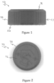
Figure 1 is a side elevation of a closure formed according to the present invention; -
Figure 2 is a plan view of the closure ofFigure 1 ; -
Figure 3 is a perspective view of the top side of an outer cap forming part of the closure ofFigures 1 and 2 ; -
Figure 4 is a perspective bottom side view of the outer cap ofFigure 3 ; -
Figure 5 is a perspective view of the top side of an inner cap forming part of the closure ofFigures 1 and 2 ; -
Figure 6 is a perspective bottom side view of the inner cap ofFigure 5 ; -
Figure 7 is a magnified view of the side of the inner cap ofFigures 5 and 6 illustrating an assembly rib and drive formation; -
Figure 8 is a further magnified view of the rib and drive formation ofFigure 7 ; -
Figure 9 is a magnified plan view of the inner cap illustrating an improved ramp and detent; -
Figure 10 is a magnified perspective view of the ramp and detent ofFigure 9 ; -
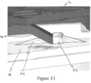
Figure 1 1 is a cut-away perspective view illustrating driving engagement of spring fingers on the outer cap with the ramp and detent on the inner cap; -
Figure 12 is a cut-away side perspective view illustrating the fingers ofFigure 1 1 sliding over the ramp in an unscrewing direction; -
Figure 13 is a cut-away rear perspective view of the illustration ofFigure 12 ; -
Figure 14 is a magnified plan view showing the region of a ramp and detent projection of the inner cap; -
Figure 15 is a perspective view of the region ofFigure 15 ; -
Figure 16 is an underplan view of anouter cap 115 formed according to an alternative embodiment; -
Figure 17 a plan view of an inner cap for use in conjunction with the outer cap ofFigure 16 ; and -
Figure 18 is an underplan view of theinner cap 125 is shown fitted with a disc-shape seal. - In
Figures 1 and 2 a closure is shown generally indicated 10. Theclosure 10 is made up of two components: anouter cap 15, shown inFigures 3 and 4 aninner cap 25, shown inFigures 5 and 6 . - The
outer cap 15 is formed with a circulartop panel 16 integrally moulded with a dependingcylindrical skirt 17. Formed on the underside of thetop panel 16 and extending into the interior of theouter cap 15 are a plurality of finger-like spring members 18. - The embodiment illustrated shows six
spring members 18, but as few as one or two members may operate satisfactorily, and more than six members may be employed if desired. Thespring members 18 take the form of inclined tabs integrally formed with the underside of thetop panel 16. Thespring members 18 are inclined at an angle of about 45 degrees with respect to the vertical axis of theouter member 10; however, the angle of inclination may be varied as long as a ratcheting function, to be described later, can be properly performed. It will also be noted that thespring members 18 are positioned radially inwards of the periphery of thepanel 16. The fingers are curved along their length with generally the same radius of curvature as thesidewall 17. - In addition to the
spring members 18, a plurality of drive lugs 19 are also moulded into the underside of thetop panel 16 and depend downwardly. The drive lugs 19 are located adjacent to the extreme outer portion of the inside diameter of theouter cap 15 adjacent the dependingskirt 17. The drive lugs 19 then extend inwardly toward thesprings 18 but their edges terminate before reaching thespring members 18. The illustration of five drive lugs 19 is by way of example and a single drive lug would function properly; but multiple drive lugs are preferred to allow a number of different removal engagement positions. - On the outer surface of the side skirt 27 a plurality of
assembly ribs 20 are provided. Theribs 20 extend axially along the skirt and project outwardly therefrom. There are sixribs 20, each one being associated with arespective drive lug 19. - In this embodiment the
ribs 20 extend along substantially the full height of theskirt 27. Theribs 20 also extend into and merge with the drive lugs, each connecting to the leading edge (i.e. the edge which is used to provide drive in use) of a respective castellated drive lug. Theribs 20 allow for the venting of pressure build up as the inner and outer caps are assembled together (see below for further details). In addition, the ribs provide additional strength to support the edge of the drive lug used for engagement when unscrewing the closure. This additional strength allows, in this embodiment, for a thinning of the drive lugs in non-functioning areas. Accordingly thelugs 19 have a very generally shallow U-shape configuration. - A
retention bead 21 is moulded into the interior wall of the dependingskirt 17 near the open end of the dependingskirt 17. Thebead 21 is continuous about the entire circumference of the dependingskirt 17. - The
outer cap 15 may be manufactured of any material sufficiently resilient to provide the necessary spring quality for the integrally mouldedspring members 18, for example polyethylene and propylene. - The
inner cap 25 is also formed as an integral unit having a circulartop panel 26 and a dependingskirt 27 attached thereto. - The interior of the depending
skirt 27 is provided with ascrew thread 28 for engagement with a threaded neck finish of a container. - The upper portion of the
inner cap member 25 is of a general configuration that may be considered to be castellated. Aring wall 33 rises above the plane of thetop panel 26. - Spaced at intervals around the
ring wall 33 are upwardly or axially extending castellation-like drive projections 34. In the assembled closure, the drive lugs 19 on the interior of theouter cap 15 are sized such that they may mesh into the openings between thedrive projections 34. This imparts a driving force to theinner cap member 25 so that it may be driven by theouter cap 15. - A
retention bead 35 is moulded into the exterior surface of the dependingskirt 27. Theretention bead 35 extends about the entire circumference of the dependingskirt 27 and is of a diameter greater than that of theretention bead 21 formed in the dependingskirt 17 of theouter cap 15. - Referring also to
Figures 14 and 15 , projecting vertically up from and formed integrally with thetop panel 26 are a plurality of ratchet lug means. In the embodiment shown the ratchet lug means take the form of six ramp-type lugs 29. Each of the ramp lugs 29 has a substantially L-shaped configuration formed by aninclined ramp portion 30 joined to a radially extending, axially projectingvertical wall portion 31. The beginning of the ramp portion is in a plane substantially identical to the plane of thetop panel 26. Thevertical wall portion 31 terminates with anabutment face 31a and is at an elevation such that thespring members 18 will jam on theface 31a if it is attempted to pass them by thevertical wall portion 31. Thewall portion 31 extends radially inwards from thering wall 33, approximately from the middle of thedrive projection 34. - The
ramp portion 30 is shaped and profiled so as to be sympathetic to the trajectory of the spring fingers as they pass over in use. The portion has a variable section sweep with a section that varies as the ramp height increases i.e. the ramp face is not flat. The trajectory of the portion has a constant radius; the section that sweeps along the radius is constantly changing (in both X and Y planes). This allows the spring finger to be in maximum contact with the ramp through rotation so that there is no time at which there is only a point contact between them. This allows for a ramp to be formed with the minimum amount of material whilst providing maximum contact with the finger during rotation. - Spaced between each of the ramp lugs 29 are hump-like, arcuately extending
detent projections 32. Thedetent projections 32 project above the plane of thetop panel 26 and lie in the path of travel of thespring members 18 in use. As discussed further below, theprojections 32 hold thespring members 18 in place during application of the closure to transmit the force directly to theramp face 31a and help stop the finger deforming back on itself. The profile of thefront section 32a of the projections is selected to match the corresponding shape of the part of the spring members which lie over them in use (seeFigure 11 ) so that the support they provide is maximised. Thesides ramp 30. - The
inner cap 25 is an independent closure in itself for a container. The inner 25 therefore may be made of any suitable material and need not necessarily be made of the same material as that of theouter cap 15; a thermoplastic material such as polyethylene or polypropylene may, for example, be used. - The
closure 10 is formed by assembling theouter cap 15 and theinner cap 25. To assemble the completed closure, theretention bead 21 is forced over theretention bead 35, in the process causing the dependingskirt 17 of the outerclosure cap member 10 to spring outwardly slightly. Once thesretention bead 21 has passed over theretention bead 35, the dependingskirt 17 springs back inwardly trapping theinner cap 15 within theouter cap 25. The fit between theouter cap 15 and theinner cap 25 is not tight. There is an appreciable gap between the interior of the dependingskirt 16 and the exterior of the dependingskirt 32. Thus, theouter cap 15 may both rotate and axially slide with respect to theinner cap 25. - In use the
inner cap 25 is threadably engaged on an exteriorly threaded finish of a container. A sealing disk (not shown) may be provided in theinner cap 25 and will be trapped between the upper portion of the finish and the lower portion of the top panel of theinner cap 25. - When the
outer cap 15 is rotated clockwise thespring members 18 are moved so as to become in driving engagement withrespective faces 31a as shown inFigure 1 1 . Thus, the completed closure may be screwed onto the finish of a container, since the rotation of theouter cap 15 will cause thespring members 18 to drivingly engage the ratchet lugs 29 and consequently turn theouter cap 15 and theinner cap 25 as a unit in the tightening direction. - In the tightening direction, the
spring members 18 wedge between theramps 29 and theprojections 32. - Conversely, as illustrated in
Figures 12 and 13 it may be seen that if theouter cap 15 is rotated in the opposite direction or the direction normally unscrewing the cap from the container, thesprings 18 slip over the ratchet lugs 29. The profile of theramp 30 changes constantly as the ramp height increases. This allows for maximum support to be provided to thespring fingers 18. - Thus, these two functions provide a one-way ratchet drive for the
inner cap 25. Theouter cap 15 thus can rotate freely with respect to theinner cap 25 in the unscrewing direction. It is this feature which makes the closure child-resistant, since it is impossible to unscrew the combined closure without an additional motion. - The
detent projections 32 act as a further safety feature. If theouter cap 15 is turned in a direction which would normally unscrew the combined closure from the finish, once thesprings 18 have risen completely up theramp portion 30 of the ramp lugs 29 and fallen off the opposite side, thedetent projections 32 will tend to hold thesprings 18 in that position. It is necessary then to exert further force to move theleaf springs 18 to the next ramp to raise it up theramp portion 30. In addition, thedetent projections 32 are positioned such that the drive lugs 19 are aligned with thedrive projections 34 when thesprings 18 are stopped by thedetent projections 32. This position helps prevent overstressing of thesprings 18 when the closure is subjected to a vertical load, as in a warehouse. The drive lugs 19 are in contact with thedrive projections 34 to prevent this overstressing. - In this embodiment the
ramps 30 andprojections 32 are shaped and profiled so that they support the edge/tip of the spring finger during substantially the entire time it is in contact with these features. - To remove the closure from a container finish, the
outer cap 15 must be compressed downwardly over theinner cap 25. - The
spring members 18 serve to normally keep theouter cap 15 and theinner cap 25 in their axially spaced relationship, in which removal of the closure from the container is impossible. However, utilising the spring function of thesprings 18, theouter cap 15 may be pressed downwardly over theinner cap 25. The downward displacement of theouter cap 15 brings the drive lugs 19 into engagement with the spaces between thedrive projections 34. - Alignment of the drive lugs 19 and the spaces between the
drive projections 34 may not be perfect at the time theouter cap 15 is pressed downwardly. However, slight rotation of theouter cap 15 in the loosening direction will bring these members into proper drive engagement. With the drive lugs 19 properly engaged, theouter cap 15 may be rotated and theinner cap 25 will rotate with it as a unit through this driving engagement. - Once the combined closure is removed from the container and the downward pressure on the
outer cap 15 is released, the combined closure will spring back under the influence of thespring member 18, thereby placing the closure in configuration suitable for reapplication. The user may then screw the closure back onto the container finish utilising the driving engagement of thesprings 18 and the ratchet lugs 29. - Once back on the container, the combined closure may not be removed again without the downward compression of the
outer cap 15 over theinner cap 25. When a child attempts to remove the assembled closure from a container without pressing downwardly on theouter cap 15, an audible warning sound is produced. Thesprings 18 slipping over the ratchet lugs 29 and hitting thetop panel 26 produces a loud and distinctive "clicking" sound. This sound may be heard for some distance and can serve as a warning to parents that children are tampering with a container whose contents may be harmful to them. - The closure of this invention assembled from the
outer cap 15 and theinner cap 25 may be applied by conventional capping machinery, since there is no need for any manipulation of the closure during the tightening procedure. - In
Figure 16 the interior of an outer cap 1 15 formed according to an alternative embodiment is shown. Thecap 115 is very similar to thecap 15. The curved spring members 118 and the U-shape drive lugs 1 19 can clearly be seen. - In
Figure 17 a plan view of aninner cap 125 for use in conjunction with theouter cap 115 is shown. - In
Figure 18 an underplan view of theinner cap 125 is shown. The inner cap has been fitted with a disc-shape seal 140 which in this embodiment is attached to the underside of thetop panel 126 so that it can seal against the rim of a container neck in use. - Although illustrative embodiments of the invention have been disclosed in detail herein, with reference to the accompanying drawings, it is understood that the invention is not limited to the precise embodiments shown and that various changes and modifications can be effected therein by one skilled in the art without departing from the scope of the invention as defined by the appended claims .
Claims (8)
- A child-resistant closure (10) for a container, the child-resistant closure (10) comprising outer and inner nested caps (15, 25) each having a top panel (16, 26) and a side skirt (17, 27) depending generally peripherally therefrom, said outer cap (15) loosely generally encompassing said inner cap (25) to allow relative rotary and axial movement therebetween, the rotary movement being in a direction of rotation around a longitudinal axis of the child-resistant closure (10), the axial movement being in a direction along said longitudinal axis, the outer and inner caps (15, 25) having corresponding drive formations (19, 34) which can be brought into driving engagement when the outer and inner caps (15, 25) are moved axially towards one another to a first axial position, one of the outer and inner caps (15, 25) comprising one or more spring members (18) for urging the outer and inner caps (15, 25) axially away from each other to a second axial position, the other of the outer and inner caps (15, 25) comprising one or more ramps (29), the one or more spring members (18) providing a biasing force to maintain said outer and inner caps (15, 25) in the second axial position and drivingly engaging the ramps (29) in the second axial position so as to drive the outer and inner caps (15, 25) together in a screwing direction, the screwing direction being in a first direction of rotation around said longitudinal axis, but slipping over the one or more ramps (29) freely in an unscrewing direction the unscrewing direction being in a second direction of rotation around said longitudinal axis, the second direction of rotation opposite the first direction of rotation, downward pressure on the outer cap (25) overcoming the spring member bias to move the outer and inner caps (15, 25) to the first axial position to allow unscrewing of the child-resistant closure (10) using the drive formations (19, 34), in which the or each ramp (29) is profiled to support the one or more spring members (18) substantially continuously as the spring member passes over in the unscrewing direction, characterised in that the or each ramp (29) has a variable section sweep having a generally constant radius trajectory and a section that sweeps along the radius that constantly changes, in which the section varies as the ramp height increases, such that the ramp face is not flat, and in which the profile of the ramp (29) constantly changes as the ramp height increases, and the ramp height increases in the unscrewing direction, whereby the or each spring member is in maximum contact with the or each ramp through rotation in the unscrewing direction.
- A child-resistant closure (10) as claimed in claim 1, in which an external surface of the side skirt (27) of the inner cap (25) includes one or more axial ribs (20) for allowing venting when the outer and inner caps (15, 25) are initially assembled together.
- A child-resistant closure (10) as claimed in claim 2, in which the or each axial rib (20) is formed integrally with a drive formation (34) to strengthen the drive formation (34).
- A child-resistant closure (10) as claimed in claim 3, in which the or each axial rib (20) connects to an edge of the drive formation (34) which, in use, engages drivingly with a drive formation (19) on the outer cap (15).
- A child-resistant closure (10) as claimed in any of claims 2 to 4, in which the or each axial rib (20) extends along substantially the entire length of the side skirt (27).
- A child-resistant closure (10) as claimed in any of claims 2 to 5, in which each drive formation (34) on the inner cap (15) has a respective axial rib (20).
- A child-resistant closure (10) as claimed in any preceding claim, in which for the or each ramp (29) a respective detent projection (32) is provided which projects above a plane of the top (26) panel and lies in the path of travel of the or each spring members (18), the detent projection (32) supports the spring member (18) when in driving engagement with the ramp (29) to resist deformation of the spring member (18) as it transmits force to a face of the ramp (29), and a profile of the detent projection (32) matches a profile of the region of the spring member (18) in contact therewith.
- A child-resistant closure (10) as claimed in any preceding claim in combination with a container.
Priority Applications (1)
| Application Number | Priority Date | Filing Date | Title |
|---|---|---|---|
| EP18162267.1A EP3381832B1 (en) | 2013-10-30 | 2014-09-05 | A child-resistant closure |
Applications Claiming Priority (2)
| Application Number | Priority Date | Filing Date | Title |
|---|---|---|---|
| GBGB1319118.4A GB201319118D0 (en) | 2013-10-30 | 2013-10-30 | A child-resistant closure |
| PCT/EP2014/069008 WO2015062771A1 (en) | 2013-10-30 | 2014-09-05 | A child-resistant closure |
Related Child Applications (2)
| Application Number | Title | Priority Date | Filing Date |
|---|---|---|---|
| EP18162267.1A Division-Into EP3381832B1 (en) | 2013-10-30 | 2014-09-05 | A child-resistant closure |
| EP18162267.1A Division EP3381832B1 (en) | 2013-10-30 | 2014-09-05 | A child-resistant closure |
Publications (3)
| Publication Number | Publication Date |
|---|---|
| EP3066020A1 EP3066020A1 (en) | 2016-09-14 |
| EP3066020B1 true EP3066020B1 (en) | 2023-07-26 |
| EP3066020C0 EP3066020C0 (en) | 2023-07-26 |
Family
ID=49767347
Family Applications (2)
| Application Number | Title | Priority Date | Filing Date |
|---|---|---|---|
| EP14777279.2A Active EP3066020B1 (en) | 2013-10-30 | 2014-09-05 | A child-resistant closure |
| EP18162267.1A Active EP3381832B1 (en) | 2013-10-30 | 2014-09-05 | A child-resistant closure |
Family Applications After (1)
| Application Number | Title | Priority Date | Filing Date |
|---|---|---|---|
| EP18162267.1A Active EP3381832B1 (en) | 2013-10-30 | 2014-09-05 | A child-resistant closure |
Country Status (5)
| Country | Link |
|---|---|
| US (1) | US9902535B2 (en) |
| EP (2) | EP3066020B1 (en) |
| CN (1) | CN105764805B (en) |
| GB (1) | GB201319118D0 (en) |
| WO (1) | WO2015062771A1 (en) |
Families Citing this family (16)
| Publication number | Priority date | Publication date | Assignee | Title |
|---|---|---|---|---|
| US10676256B2 (en) | 2013-10-30 | 2020-06-09 | Obrist Closures Switzerland Gmbh | Child-resistant closure |
| BR112017023477B1 (en) * | 2015-06-16 | 2021-10-05 | Amcor Group Gmbh | CHILD RESISTANT DROPPER CLOSURE |
| GB2546244B (en) * | 2015-12-29 | 2018-05-30 | Origin Packaging Ltd | Child resistant closure |
| CN109661353B (en) * | 2016-06-22 | 2020-12-29 | 科莱恩保健品包装简易股份有限公司 | Tamper evident closure, container with such closure and use thereof |
| JP1602419S (en) * | 2017-09-15 | 2021-04-19 | ||
| JP1602420S (en) * | 2017-09-15 | 2021-04-19 | ||
| CN107954080B (en) * | 2017-12-12 | 2023-09-29 | 广州雅塑包装技术服务有限公司 | Easy-to-open bottle cap structure |
| CN111971234B (en) * | 2018-01-26 | 2023-02-17 | 奥布里斯特封闭瑞士有限公司 | child safety cover |
| US10414561B1 (en) | 2018-07-03 | 2019-09-17 | Pascal Holdings, LLC | Safety cap |
| USD929230S1 (en) * | 2019-01-25 | 2021-08-31 | Obrist Closures Switzerland Gmbh | Closure for containers |
| EP3870519A4 (en) * | 2019-12-06 | 2022-11-16 | Chubby Gorilla, Inc. | Safety-cap bottle assembly |
| CN212173124U (en) * | 2020-09-30 | 2020-12-18 | 东莞市鑫宇制罐有限公司 | Packing carton with safety lock function |
| US12157613B2 (en) | 2022-01-28 | 2024-12-03 | Berry Global, Inc. | Selectively openable closure for a container |
| GB202217715D0 (en) * | 2022-11-25 | 2023-01-11 | Obrist Closures Switzerland | A child-resistant closure |
| US20240391662A1 (en) * | 2023-05-23 | 2024-11-28 | Oralabs, Inc. | Safety cap assembly with air passage to prevent suffocation |
| WO2025025214A1 (en) * | 2023-08-03 | 2025-02-06 | 上海鸿洋创智包装有限公司 | Sleeve gift box with child lock |
Citations (1)
| Publication number | Priority date | Publication date | Assignee | Title |
|---|---|---|---|---|
| WO1993001098A2 (en) * | 1991-07-10 | 1993-01-21 | Beeson And Sons Limited | Improvements relating to a container, to a container neck, to a closure therefor, and to the manufacture thereof |
Family Cites Families (14)
| Publication number | Priority date | Publication date | Assignee | Title |
|---|---|---|---|---|
| US3830390A (en) | 1972-03-22 | 1974-08-20 | Sunbeam Plastics Corp | Safety closure for medicine bottles or the like |
| US3857505A (en) | 1973-10-01 | 1974-12-31 | Owens Illinois Inc | Safety closure |
| US4394916A (en) * | 1982-03-29 | 1983-07-26 | Owens-Illinois, Inc. | Child-resistant closure assembly |
| GB2142612B (en) | 1983-07-01 | 1987-06-10 | Puresevic Peter J | A child proof and tamper indicating closure |
| US5588545A (en) | 1991-09-23 | 1996-12-31 | Beeson And Sons Limited | Child-resistant and elderly friendly closure for containers |
| IT1291620B1 (en) | 1997-04-18 | 1999-01-11 | Phaba Srl | Childproof closure for medicine bottles which enables easier operation and improved safety |
| US6206216B1 (en) | 1999-07-26 | 2001-03-27 | Top Seal Corporation | Child-resistant cap |
| WO2004063025A2 (en) * | 2003-01-08 | 2004-07-29 | Tri State Distribution, Inc. | Shellable child resistant closure container with positive lock mechanism |
| US7922017B2 (en) * | 2005-05-12 | 2011-04-12 | Rexam Prescription Products Inc. | Child-resistant closure, container and package convertible to non-child-resistant operation |
| KR100913599B1 (en) * | 2007-09-17 | 2009-08-26 | 최정구 | Anti-counterfeit stopper |
| US20110147334A1 (en) * | 2009-02-16 | 2011-06-23 | Sumanth Kumar Reddy Mettu | Child resistant closure with improved assembly |
| US8534476B2 (en) * | 2009-12-11 | 2013-09-17 | Rexam Healthcare Packaging Inc. | Child-resistant closure shell, closure, and package |
| US8474634B1 (en) * | 2010-04-30 | 2013-07-02 | Rexam Healthcare Packaging Inc. | Child resistant closure with vents |
| US8857638B2 (en) * | 2010-12-03 | 2014-10-14 | Bprex Healthcare Packaging Inc. | Push-and-turn child-resistant closure, shells, and package |
-
2013
- 2013-10-30 GB GBGB1319118.4A patent/GB201319118D0/en not_active Ceased
-
2014
- 2014-09-05 CN CN201480057093.XA patent/CN105764805B/en active Active
- 2014-09-05 US US15/031,245 patent/US9902535B2/en active Active
- 2014-09-05 EP EP14777279.2A patent/EP3066020B1/en active Active
- 2014-09-05 WO PCT/EP2014/069008 patent/WO2015062771A1/en not_active Ceased
- 2014-09-05 EP EP18162267.1A patent/EP3381832B1/en active Active
Patent Citations (1)
| Publication number | Priority date | Publication date | Assignee | Title |
|---|---|---|---|---|
| WO1993001098A2 (en) * | 1991-07-10 | 1993-01-21 | Beeson And Sons Limited | Improvements relating to a container, to a container neck, to a closure therefor, and to the manufacture thereof |
Also Published As
| Publication number | Publication date |
|---|---|
| GB201319118D0 (en) | 2013-12-11 |
| CN105764805B (en) | 2017-12-05 |
| EP3066020A1 (en) | 2016-09-14 |
| US9902535B2 (en) | 2018-02-27 |
| WO2015062771A1 (en) | 2015-05-07 |
| US20160251127A1 (en) | 2016-09-01 |
| EP3381832A1 (en) | 2018-10-03 |
| EP3381832B1 (en) | 2024-11-06 |
| EP3066020C0 (en) | 2023-07-26 |
| CN105764805A (en) | 2016-07-13 |
Similar Documents
| Publication | Publication Date | Title |
|---|---|---|
| EP3381832B1 (en) | A child-resistant closure | |
| US10676256B2 (en) | Child-resistant closure | |
| US20230322451A1 (en) | Closure Assembly | |
| US5280842A (en) | Low reverse torque closure assembly | |
| US9889977B2 (en) | Child-resistant closure | |
| EP2010435B1 (en) | Tapered thread structure | |
| US4562931A (en) | Pilfer-proof closure with tear-away holding claws | |
| EP1615836B1 (en) | Tamper-evident container | |
| US6681945B1 (en) | Child resistant overcap for oval container | |
| EP3269661B1 (en) | Vacuum release seal for a closure and container package | |
| GB2467355A (en) | Container closure with pressure seal | |
| US9771190B2 (en) | Child-resistant closure | |
| CN107249995B (en) | screw cap container | |
| CN102470959B (en) | Child resistant closure with stacking position | |
| US10689164B2 (en) | Container with heat-sealed composite plastic and metal screw closure | |
| JP6660244B2 (en) | Screw lid type container | |
| EP3743351B1 (en) | A child-resistant closure | |
| US7469794B2 (en) | Child resistant container-closure assembly | |
| US7819265B2 (en) | Child-resistant closure and container package | |
| EP4622887A1 (en) | A child-resistant closure | |
| GB2236308A (en) | Safety cap for a container |
Legal Events
| Date | Code | Title | Description |
|---|---|---|---|
| PUAI | Public reference made under article 153(3) epc to a published international application that has entered the european phase |
Free format text: ORIGINAL CODE: 0009012 |
|
| 17P | Request for examination filed |
Effective date: 20160504 |
|
| AK | Designated contracting states |
Kind code of ref document: A1 Designated state(s): AL AT BE BG CH CY CZ DE DK EE ES FI FR GB GR HR HU IE IS IT LI LT LU LV MC MK MT NL NO PL PT RO RS SE SI SK SM TR |
|
| AX | Request for extension of the european patent |
Extension state: BA ME |
|
| RIN1 | Information on inventor provided before grant (corrected) |
Inventor name: FARAGHER, STEPHEN |
|
| DAX | Request for extension of the european patent (deleted) | ||
| STAA | Information on the status of an ep patent application or granted ep patent |
Free format text: STATUS: EXAMINATION IS IN PROGRESS |
|
| 17Q | First examination report despatched |
Effective date: 20170619 |
|
| GRAP | Despatch of communication of intention to grant a patent |
Free format text: ORIGINAL CODE: EPIDOSNIGR1 |
|
| STAA | Information on the status of an ep patent application or granted ep patent |
Free format text: STATUS: GRANT OF PATENT IS INTENDED |
|
| INTG | Intention to grant announced |
Effective date: 20230301 |
|
| P01 | Opt-out of the competence of the unified patent court (upc) registered |
Effective date: 20230512 |
|
| GRAS | Grant fee paid |
Free format text: ORIGINAL CODE: EPIDOSNIGR3 |
|
| GRAA | (expected) grant |
Free format text: ORIGINAL CODE: 0009210 |
|
| STAA | Information on the status of an ep patent application or granted ep patent |
Free format text: STATUS: THE PATENT HAS BEEN GRANTED |
|
| AK | Designated contracting states |
Kind code of ref document: B1 Designated state(s): AL AT BE BG CH CY CZ DE DK EE ES FI FR GB GR HR HU IE IS IT LI LT LU LV MC MK MT NL NO PL PT RO RS SE SI SK SM TR |
|
| RAP3 | Party data changed (applicant data changed or rights of an application transferred) |
Owner name: OBRIST CLOSURES SWITZERLAND GMBH |
|
| REG | Reference to a national code |
Ref country code: CH Ref legal event code: EP |
|
| REG | Reference to a national code |
Ref country code: IE Ref legal event code: FG4D |
|
| REG | Reference to a national code |
Ref country code: DE Ref legal event code: R096 Ref document number: 602014087752 Country of ref document: DE |
|
| U01 | Request for unitary effect filed |
Effective date: 20230808 |
|
| U07 | Unitary effect registered |
Designated state(s): AT BE BG DE DK EE FI FR IT LT LU LV MT NL PT SE SI Effective date: 20230816 |
|
| P04 | Withdrawal of opt-out of the competence of the unified patent court (upc) registered |
Effective date: 20230811 |
|
| U20 | Renewal fee for the european patent with unitary effect paid |
Year of fee payment: 10 Effective date: 20230926 |
|
| REG | Reference to a national code |
Ref country code: LT Ref legal event code: MG9D |
|
| PG25 | Lapsed in a contracting state [announced via postgrant information from national office to epo] |
Ref country code: GR Free format text: LAPSE BECAUSE OF FAILURE TO SUBMIT A TRANSLATION OF THE DESCRIPTION OR TO PAY THE FEE WITHIN THE PRESCRIBED TIME-LIMIT Effective date: 20231027 |
|
| PG25 | Lapsed in a contracting state [announced via postgrant information from national office to epo] |
Ref country code: IS Free format text: LAPSE BECAUSE OF FAILURE TO SUBMIT A TRANSLATION OF THE DESCRIPTION OR TO PAY THE FEE WITHIN THE PRESCRIBED TIME-LIMIT Effective date: 20231126 |
|
| PG25 | Lapsed in a contracting state [announced via postgrant information from national office to epo] |
Ref country code: RS Free format text: LAPSE BECAUSE OF FAILURE TO SUBMIT A TRANSLATION OF THE DESCRIPTION OR TO PAY THE FEE WITHIN THE PRESCRIBED TIME-LIMIT Effective date: 20230726 Ref country code: NO Free format text: LAPSE BECAUSE OF FAILURE TO SUBMIT A TRANSLATION OF THE DESCRIPTION OR TO PAY THE FEE WITHIN THE PRESCRIBED TIME-LIMIT Effective date: 20231026 Ref country code: IS Free format text: LAPSE BECAUSE OF FAILURE TO SUBMIT A TRANSLATION OF THE DESCRIPTION OR TO PAY THE FEE WITHIN THE PRESCRIBED TIME-LIMIT Effective date: 20231126 Ref country code: HR Free format text: LAPSE BECAUSE OF FAILURE TO SUBMIT A TRANSLATION OF THE DESCRIPTION OR TO PAY THE FEE WITHIN THE PRESCRIBED TIME-LIMIT Effective date: 20230726 Ref country code: GR Free format text: LAPSE BECAUSE OF FAILURE TO SUBMIT A TRANSLATION OF THE DESCRIPTION OR TO PAY THE FEE WITHIN THE PRESCRIBED TIME-LIMIT Effective date: 20231027 |
|
| PG25 | Lapsed in a contracting state [announced via postgrant information from national office to epo] |
Ref country code: PL Free format text: LAPSE BECAUSE OF FAILURE TO SUBMIT A TRANSLATION OF THE DESCRIPTION OR TO PAY THE FEE WITHIN THE PRESCRIBED TIME-LIMIT Effective date: 20230726 |
|
| PG25 | Lapsed in a contracting state [announced via postgrant information from national office to epo] |
Ref country code: ES Free format text: LAPSE BECAUSE OF FAILURE TO SUBMIT A TRANSLATION OF THE DESCRIPTION OR TO PAY THE FEE WITHIN THE PRESCRIBED TIME-LIMIT Effective date: 20230726 |
|
| REG | Reference to a national code |
Ref country code: DE Ref legal event code: R097 Ref document number: 602014087752 Country of ref document: DE |
|
| PG25 | Lapsed in a contracting state [announced via postgrant information from national office to epo] |
Ref country code: SM Free format text: LAPSE BECAUSE OF FAILURE TO SUBMIT A TRANSLATION OF THE DESCRIPTION OR TO PAY THE FEE WITHIN THE PRESCRIBED TIME-LIMIT Effective date: 20230726 Ref country code: RO Free format text: LAPSE BECAUSE OF FAILURE TO SUBMIT A TRANSLATION OF THE DESCRIPTION OR TO PAY THE FEE WITHIN THE PRESCRIBED TIME-LIMIT Effective date: 20230726 Ref country code: ES Free format text: LAPSE BECAUSE OF FAILURE TO SUBMIT A TRANSLATION OF THE DESCRIPTION OR TO PAY THE FEE WITHIN THE PRESCRIBED TIME-LIMIT Effective date: 20230726 Ref country code: CZ Free format text: LAPSE BECAUSE OF FAILURE TO SUBMIT A TRANSLATION OF THE DESCRIPTION OR TO PAY THE FEE WITHIN THE PRESCRIBED TIME-LIMIT Effective date: 20230726 Ref country code: SK Free format text: LAPSE BECAUSE OF FAILURE TO SUBMIT A TRANSLATION OF THE DESCRIPTION OR TO PAY THE FEE WITHIN THE PRESCRIBED TIME-LIMIT Effective date: 20230726 |
|
| REG | Reference to a national code |
Ref country code: CH Ref legal event code: PL |
|
| PG25 | Lapsed in a contracting state [announced via postgrant information from national office to epo] |
Ref country code: MC Free format text: LAPSE BECAUSE OF FAILURE TO SUBMIT A TRANSLATION OF THE DESCRIPTION OR TO PAY THE FEE WITHIN THE PRESCRIBED TIME-LIMIT Effective date: 20230726 |
|
| PLBE | No opposition filed within time limit |
Free format text: ORIGINAL CODE: 0009261 |
|
| STAA | Information on the status of an ep patent application or granted ep patent |
Free format text: STATUS: NO OPPOSITION FILED WITHIN TIME LIMIT |
|
| 26N | No opposition filed |
Effective date: 20240429 |
|
| REG | Reference to a national code |
Ref country code: IE Ref legal event code: MM4A |
|
| PG25 | Lapsed in a contracting state [announced via postgrant information from national office to epo] |
Ref country code: IE Free format text: LAPSE BECAUSE OF NON-PAYMENT OF DUE FEES Effective date: 20230905 |
|
| PG25 | Lapsed in a contracting state [announced via postgrant information from national office to epo] |
Ref country code: CH Free format text: LAPSE BECAUSE OF NON-PAYMENT OF DUE FEES Effective date: 20230930 |
|
| PG25 | Lapsed in a contracting state [announced via postgrant information from national office to epo] |
Ref country code: IE Free format text: LAPSE BECAUSE OF NON-PAYMENT OF DUE FEES Effective date: 20230905 Ref country code: CH Free format text: LAPSE BECAUSE OF NON-PAYMENT OF DUE FEES Effective date: 20230930 |
|
| U20 | Renewal fee for the european patent with unitary effect paid |
Year of fee payment: 11 Effective date: 20240926 |
|
| P05 | Withdrawal of opt-out of the competence of the unified patent court (upc) changed |
Free format text: CASE NUMBER: APP_561106/2023 Effective date: 20230816 |
|
| PG25 | Lapsed in a contracting state [announced via postgrant information from national office to epo] |
Ref country code: CY Free format text: LAPSE BECAUSE OF FAILURE TO SUBMIT A TRANSLATION OF THE DESCRIPTION OR TO PAY THE FEE WITHIN THE PRESCRIBED TIME-LIMIT; INVALID AB INITIO Effective date: 20140905 |
|
| PG25 | Lapsed in a contracting state [announced via postgrant information from national office to epo] |
Ref country code: HU Free format text: LAPSE BECAUSE OF FAILURE TO SUBMIT A TRANSLATION OF THE DESCRIPTION OR TO PAY THE FEE WITHIN THE PRESCRIBED TIME-LIMIT; INVALID AB INITIO Effective date: 20140905 |
|
| PGFP | Annual fee paid to national office [announced via postgrant information from national office to epo] |
Ref country code: GB Payment date: 20250923 Year of fee payment: 12 |
|
| U20 | Renewal fee for the european patent with unitary effect paid |
Year of fee payment: 12 Effective date: 20250925 |
|
| PG25 | Lapsed in a contracting state [announced via postgrant information from national office to epo] |
Ref country code: TR Free format text: LAPSE BECAUSE OF FAILURE TO SUBMIT A TRANSLATION OF THE DESCRIPTION OR TO PAY THE FEE WITHIN THE PRESCRIBED TIME-LIMIT Effective date: 20230726 |