EP3065842B1 - Backwash arrangement for cleaning a cylindrical filter screen - Google Patents
Backwash arrangement for cleaning a cylindrical filter screen Download PDFInfo
- Publication number
- EP3065842B1 EP3065842B1 EP14859433.6A EP14859433A EP3065842B1 EP 3065842 B1 EP3065842 B1 EP 3065842B1 EP 14859433 A EP14859433 A EP 14859433A EP 3065842 B1 EP3065842 B1 EP 3065842B1
- Authority
- EP
- European Patent Office
- Prior art keywords
- filter screen
- arrangement
- cylindrical filter
- nozzle
- backwash
- Prior art date
- Legal status (The legal status is an assumption and is not a legal conclusion. Google has not performed a legal analysis and makes no representation as to the accuracy of the status listed.)
- Active
Links
- 238000004140 cleaning Methods 0.000 title claims description 13
- 239000002245 particle Substances 0.000 claims description 8
- 238000005096 rolling process Methods 0.000 claims description 4
- 239000007788 liquid Substances 0.000 description 10
- 230000002093 peripheral effect Effects 0.000 description 10
- 230000000712 assembly Effects 0.000 description 7
- 238000000429 assembly Methods 0.000 description 7
- 238000001914 filtration Methods 0.000 description 6
- 238000000034 method Methods 0.000 description 4
- XLYOFNOQVPJJNP-UHFFFAOYSA-N water Substances O XLYOFNOQVPJJNP-UHFFFAOYSA-N 0.000 description 4
- 230000007246 mechanism Effects 0.000 description 3
- 238000006073 displacement reaction Methods 0.000 description 2
- 238000005299 abrasion Methods 0.000 description 1
- 238000010276 construction Methods 0.000 description 1
- 230000001419 dependent effect Effects 0.000 description 1
- 230000000694 effects Effects 0.000 description 1
- 238000009877 rendering Methods 0.000 description 1
- 239000013535 sea water Substances 0.000 description 1
- 238000007789 sealing Methods 0.000 description 1
- 238000013022 venting Methods 0.000 description 1
Images


Classifications
-
- B—PERFORMING OPERATIONS; TRANSPORTING
- B01—PHYSICAL OR CHEMICAL PROCESSES OR APPARATUS IN GENERAL
- B01D—SEPARATION
- B01D29/00—Filters with filtering elements stationary during filtration, e.g. pressure or suction filters, not covered by groups B01D24/00 - B01D27/00; Filtering elements therefor
- B01D29/62—Regenerating the filter material in the filter
- B01D29/66—Regenerating the filter material in the filter by flushing, e.g. counter-current air-bumps
- B01D29/68—Regenerating the filter material in the filter by flushing, e.g. counter-current air-bumps with backwash arms, shoes or nozzles
-
- B—PERFORMING OPERATIONS; TRANSPORTING
- B01—PHYSICAL OR CHEMICAL PROCESSES OR APPARATUS IN GENERAL
- B01D—SEPARATION
- B01D29/00—Filters with filtering elements stationary during filtration, e.g. pressure or suction filters, not covered by groups B01D24/00 - B01D27/00; Filtering elements therefor
- B01D29/11—Filters with filtering elements stationary during filtration, e.g. pressure or suction filters, not covered by groups B01D24/00 - B01D27/00; Filtering elements therefor with bag, cage, hose, tube, sleeve or like filtering elements
- B01D29/13—Supported filter elements
- B01D29/23—Supported filter elements arranged for outward flow filtration
-
- B—PERFORMING OPERATIONS; TRANSPORTING
- B01—PHYSICAL OR CHEMICAL PROCESSES OR APPARATUS IN GENERAL
- B01D—SEPARATION
- B01D29/00—Filters with filtering elements stationary during filtration, e.g. pressure or suction filters, not covered by groups B01D24/00 - B01D27/00; Filtering elements therefor
- B01D29/50—Filters with filtering elements stationary during filtration, e.g. pressure or suction filters, not covered by groups B01D24/00 - B01D27/00; Filtering elements therefor with multiple filtering elements, characterised by their mutual disposition
- B01D29/52—Filters with filtering elements stationary during filtration, e.g. pressure or suction filters, not covered by groups B01D24/00 - B01D27/00; Filtering elements therefor with multiple filtering elements, characterised by their mutual disposition in parallel connection
-
- B—PERFORMING OPERATIONS; TRANSPORTING
- B01—PHYSICAL OR CHEMICAL PROCESSES OR APPARATUS IN GENERAL
- B01D—SEPARATION
- B01D29/00—Filters with filtering elements stationary during filtration, e.g. pressure or suction filters, not covered by groups B01D24/00 - B01D27/00; Filtering elements therefor
- B01D29/62—Regenerating the filter material in the filter
- B01D29/66—Regenerating the filter material in the filter by flushing, e.g. counter-current air-bumps
- B01D29/68—Regenerating the filter material in the filter by flushing, e.g. counter-current air-bumps with backwash arms, shoes or nozzles
- B01D29/682—Regenerating the filter material in the filter by flushing, e.g. counter-current air-bumps with backwash arms, shoes or nozzles with a rotary movement with respect to the filtering element
-
- B—PERFORMING OPERATIONS; TRANSPORTING
- B01—PHYSICAL OR CHEMICAL PROCESSES OR APPARATUS IN GENERAL
- B01D—SEPARATION
- B01D29/00—Filters with filtering elements stationary during filtration, e.g. pressure or suction filters, not covered by groups B01D24/00 - B01D27/00; Filtering elements therefor
- B01D29/62—Regenerating the filter material in the filter
- B01D29/66—Regenerating the filter material in the filter by flushing, e.g. counter-current air-bumps
- B01D29/68—Regenerating the filter material in the filter by flushing, e.g. counter-current air-bumps with backwash arms, shoes or nozzles
- B01D29/688—Regenerating the filter material in the filter by flushing, e.g. counter-current air-bumps with backwash arms, shoes or nozzles with backwash arms or shoes acting on the cake side
-
- B—PERFORMING OPERATIONS; TRANSPORTING
- B01—PHYSICAL OR CHEMICAL PROCESSES OR APPARATUS IN GENERAL
- B01D—SEPARATION
- B01D2201/00—Details relating to filtering apparatus
- B01D2201/08—Regeneration of the filter
- B01D2201/081—Regeneration of the filter using nozzles or suction devices
- B01D2201/082—Suction devices placed on the cake side of the filtering element
-
- B—PERFORMING OPERATIONS; TRANSPORTING
- B01—PHYSICAL OR CHEMICAL PROCESSES OR APPARATUS IN GENERAL
- B01D—SEPARATION
- B01D2201/00—Details relating to filtering apparatus
- B01D2201/40—Special measures for connecting different parts of the filter
- B01D2201/4007—Use of cam or ramp systems
Definitions
- the present invention relates to filtering systems and, in particular, it concerns a backwash arrangement for cleaning a cylindrical filter screen.
- the present invention relates particularly to filtering systems in which liquids are passed through one or more cylindrical filter screen, and in which the inner surface of the filter screen is cleaned of accumulated debris by a backwash arrangement that generates low pressure in a suction nozzle passing over the inside of the filter screen. Debris accumulated on the internal surface of the filter screen during filtration is lifted out of the filter screen by a flow of the filtered liquid in a reverse direction (“backwash") through the screen into the nozzle, from where it is expelled from the system. Examples of such systems are described in the following patent documents: DE 19944107 , GB 1485989 , US 2008/0047885 and WO 2011/058556 .
- liquid would be drawn through the screen without leakage of unfiltered liquid from around the nozzle into the suction arrangement.
- Liquid sucked from the surroundings of the nozzle instead of through the filter screen reduces efficacy of the self-cleaning process, and results in significant wastage of energy and of liquid.
- the main factor that determines the ratio between filtered liquid backwashed through the filter and liquid leaking from around the nozzle is the proximity of the suction nozzle to the filter screen. It is therefore desirable to bring the suction nozzle as close as possible to the screen.
- the filter screens however are fine, and have significant variations (tolerances) from an exact cylindrical shape, making it difficult to reduce a clearance between the backwash nozzles and the screen.
- the present invention is a backwash arrangement for cleaning a cylindrical filter screen.
- a backwash arrangement for cleaning a cylindrical filter screen
- the backwash arrangement comprising: (a) a cylindrical filter screen; (b) a central conduit extending axially within the cylindrical filter screen; (c) a plurality of radial branch conduits extending outwards from the central conduit towards the cylindrical filter screen; and (d) a spring-loaded nozzle arrangement associated with each of the radial branch conduits, the spring-loaded nozzle arrangement being biased into contact with the cylindrical filter screen, wherein the spring-loaded nozzle arrangement comprises: (i) a nozzle opening for passing across the cylindrical filter screen, and (ii) a pair of wheels deployed on opposing sides of the nozzle opening and deployed for rolling engagement with the cylindrical filter screen.
- each of the pair of wheels has a separate axle that does not pass through a flow path from the nozzle opening along the radial branch conduit to the central conduit.
- the pair of wheels are mounted on axes of rotation parallel to an axis of the central conduit.
- a helical motion linkage associated with the central conduit and defining a path of helical motion around and along an axis of the central conduit, and wherein the pair of wheels are mounted on axes of rotation oriented to align the wheels with a helical path across the cylindrical filter screen.
- the nozzle opening has a rectangular form.
- the rectangular form has rounded corners.
- the rectangular form has a length-to-width ratio less than 10.
- the nozzle opening is defined by a nozzle block, the nozzle block further comprising a ramp surface deployed so as to tend to raise the spring-loaded nozzle arrangement over particles encountered on the cylindrical filter screen, thereby allowing the particles to enter the nozzle opening.
- the ramp surface has a dimension perpendicular to a direction of motion across the cylindrical filter screen, the dimension being substantially equal to a corresponding dimension of the nozzle opening perpendicular to the direction of motion across the cylindrical filter screen.
- the present invention is a backwash arrangement for cleaning a cylindrical filter screen.
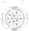
- FIGS. 1 and 2 illustrate a non-limiting exemplary filter arrangement, generally designated 10 , in which context the present invention will be illustrated.
- Filter arrangement 10 has an inlet 12 , an outlet 14 and one or more filter assemblies 16 , each including a cylindrical filter screen 18.
- filter assemblies 16 each including a cylindrical filter screen 18.
- a set of 5 filter assemblies are used in parallel, but the invention is equally applicable to filter arrangements having a single filter screen assembly, or any other number of such assemblies.
- filter arrangement 10 Operation of filter arrangement 10 is as follows. Water (or another liquid to be filtered) enters inlet 12 and passes up the inside of the filter assemblies 16 where it flows radially outwards through the cylindrical filter screens 18 , thereby undergoing filtering, before passing to outlet 14.
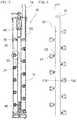
- Each filter assembly 16 features a backwash arrangement for cleaning cylindrical filter screen 18 , shown in enlarged views in FIGS. 3 and 4 .
- the backwash arrangement generally includes a central conduit 20 , extending axially within cylindrical filter screen 18 , from which a plurality of radial branch conduits 22 extend outwards.
- a spring-loaded nozzle arrangement 24 associate with each radial branch conduit 22 is a spring-loaded nozzle arrangement 24.
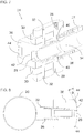
- spring-loaded nozzle arrangement 24 is best seen in FIGS. 5-8 .
- Each spring-loaded nozzle arrangement 24 is biased into contact with cylindrical filter screen 18 by a spring 26.
- Nozzle arrangement 24 defines a nozzle opening 28 for passing across the cylindrical filter screen, and a pair of wheels 30 disposed on opposing sides of nozzle opening 28 and deployed for rolling engagement with cylindrical filter screen 18.
- wheels 30 together with the biasing of spring 26 ensure intimate proximity, typically to within a fraction of a millimeter, between nozzle opening 18 and the surface of cylindrical filter screen 18 , despite significant variations in the radial spacing of the filter screen from the central conduit, thereby making the backwash process as efficient as possible.
- wheels 30 ensure that frictional wear of the nozzle arrangements 24 and of the filter screen 18 is kept to a minimum, thereby extending the lifespan of the product and reducing the frictional moment opposing operation of the motor.
- each wheel 30 preferably has a separate axle 32 that does not pass through flow path 34.
- the use of separate axles for each wheel allows an implementation as shown in which there is substantially no flow impediment within flow path 34.
- nozzle opening 28 is an opening formed in a nozzle block 36 , which is configured for sliding telescopic motion in sealing relation which radial brand conduit 22 , and which is implemented as a unitary block receiving wheel axles 32.
- Nozzle block 36 may be conveniently secured to radial branch conduit 22 by one or more locking pins 38 which engage corresponding slots 40 formed in radial branch conduit 22 , thereby locking nozzle arrangement 24 against rotation while allowing radial displacement against the bias of spring 26 as the nozzle arrangement accommodates undulations and variations in the filter screen.
- Nozzle block 36 preferably provides a peripheral surface 42 around nozzle opening 28 which is preferably shaped to conform to the internal surface of the filter screen, thereby ensuring a significant surface in close facing relation to the screen during use, thereby providing enhanced flow impedance against leakage of water around the nozzle from inside the screen.
- the arcuate curvature of peripheral surface 42 conforming to the inner surface of the cylindrical filter screen is best seen in FIG. 8 .
- the dimensions of peripheral surface 42 are preferably sufficient to provide a margin around nozzle opening which is preferably at least half of the corresponding dimension of the nozzle opening. The dimension of this margin in the axial direction is typically smaller than in the peripheral direction so as not to obstruct the nozzle from reaching the ends of the cylindrical screen.
- nozzle block 36 is preferably also provided with a ramp surface 44 deployed so as to tend to momentarily retract spring-loaded nozzle arrangement 24 so that it rides up and over any larger particles encountered on the cylindrical filter screen, so that the particles can enter the nozzle opening.
- the angle of the ramp surfaces is chosen to be sufficiently shallow to allow the nozzle to retract against its spring loading so as to ride over the particles.
- An angle ⁇ of between about 15° and about 35° to the local circumference of the cylinder is typically suitable.
- a dimension of ramp surface 44 perpendicular to the direction of motion across the cylindrical filter screen is preferably matched (substantially equal) to a corresponding dimension of nozzle opening 28 perpendicular to the direction of motion across the cylindrical filter screen.
- Ramp surfaces 44 are preferably provided symmetrically, both ahead and behind nozzle opening 28 in the direction of motion, since the backwash arrangement is typically operated bidirectionally.
- the nozzle may be designed to be "balanced", i.e., that forces resulting from a pressure difference between the outside and the inside of the nozzle do not result in a net radial force on the assembly towards the central conduit.
- slight excess spring bias may be provided to ensure that contact is maintained between the nozzle assembly and the filter screen under the expected range of working conditions.
- wheels 30 are preferably set so that their outer edges are level with the corresponding region of peripheral surface 42 to a precision of less than 1 mm difference, and most preferably to within a tolerance of about 0.2 mm. It should be noted however that precision of initial alignment is typically not critical. If peripheral surface 42 is initially slightly higher than wheels 30, since slight abrasion of the contact surface during use will typically lead to leveling of peripheral surface 42 with wheels 30 during an initial wearing-in process.
- wheels 30 may be preferably to have wheels 30 projecting slightly (typically less than a millimeter, and preferably less than half a millimeter) from peripheral surface 42 so that substantially all of the contact pressure of nozzle assembly 24 is borne by wheels 30 and frictional wear is minimized.
- nozzle opening 28 has a generally rectangular form, most preferably with rounded corners.
- the use of a rectangular form achieves a more uniform cleaning effect than a round suction nozzle since the amount of time each part of the filter is exposed to suction is close to uniform across the width swept by the nozzle opening.
- a nozzle opening with a relatively small ratio of periphery to area.
- the rectangular form of nozzle opening 28 preferably has a length-to-width ratio less than 10, and most preferably less than 5.
- a helical motion linkage 46 is associated with central conduit 20 and defines a path of helical motion around and along an axis of central conduit 20.
- Helical motion linkage 46 is typically implemented using a nut mounted near an end of central conduit 20 engaged on a fixed axial bolt, so that rotation of the central conduit results in axial displacement by the pitch of the thread for each revolution.
- the helical path preferably has a pitch (helical step) per revolution sufficiently small that successive sweeps of each nozzle opening 28 around the internal surface of the filter screen 18 cover adjacent or slightly overlapping strips, thereby providing continuous coverage of the filter screen surface.
- a rotary motion drive linkage 48 which transfers rotation directly or indirectly from one or more actuator motor.
- all of the backwash mechanisms are driven to turn simultaneously by a common drive motor 50 via a drive chain 52.
- a common drive motor is used to drive the mechanisms simultaneously, it may in some cases be desired to include a torque limiter clutch to ensure that each backwash mechanism stops exactly at the end of its range of motion.
- Actuation of drive motor 50 in one direction causes rotation of all central conduits 20 , each about its central axis, so that the nozzle arrangements 24 each move around the inner surface of the filter screen 18 with a small helical angle, effectively performing a scanning motion moving up the cylinder until each nozzle assembly reaches the starting location of the nozzle assembly above, thereby covering substantially the entire inner surface of the filter screen.
- the assembly typically remains in the end position until the next cleaning cycle is required, when the motor direction is actuated in the reverse direction so that the nozzles undergo a similar motion in reverse, returning to their original positions.
- Actuation of the backwash flow may be achieved by selective opening of a control valve (not shown) associate with a backwash outlet 54 ( FIGS. 1-3 ).
- a control valve (not shown) associate with a backwash outlet 54 ( FIGS. 1-3 ).
- the backwash outlet 54 When the backwash outlet 54 is opened, water is forced by the pressure within the filter system backwards through the nozzle assemblies 24 and radial branch conduits 22 , and along central conduit 20 to a number of venting apertures 56 which open into a backwash chamber 58 prior to release through backwash outlet 54 .
- the control valves may be opened one at a time so that only a single backwash assembly is active at any given time, even where multiple assemblies are turned simultaneously. In other applications, all of the assemblies may be operated simultaneously.
- each backwash assembly can be provided with a separate drive motor which is selectively actuated only when that backwash assembly is operative.
- nozzle block 36 and axles 32 are configured so that the axes of rotation of wheels 30 have a slight angular offset relative to the axis of central conduit 20 , corresponding to the angular pitch of the helical motion, so that they are oriented to align the wheels with the helical path of motion across cylindrical filter screen 18.
- pair of wheels 30 are mounted on axes of rotation that are parallel to the axis of central conduit 20.
Landscapes
- Chemical & Material Sciences (AREA)
- Chemical Kinetics & Catalysis (AREA)
- Filtration Of Liquid (AREA)
- Nozzles (AREA)
Description
- The present invention relates to filtering systems and, in particular, it concerns a backwash arrangement for cleaning a cylindrical filter screen.
- Large throughput filtration systems are used for treating liquids (for example, water or sea water) in a wide range of applications. The present invention relates particularly to filtering systems in which liquids are passed through one or more cylindrical filter screen, and in which the inner surface of the filter screen is cleaned of accumulated debris by a backwash arrangement that generates low pressure in a suction nozzle passing over the inside of the filter screen. Debris accumulated on the internal surface of the filter screen during filtration is lifted out of the filter screen by a flow of the filtered liquid in a reverse direction ("backwash") through the screen into the nozzle, from where it is expelled from the system. Examples of such systems are described in the following patent documents:
DE 19944107 ,GB 1485989 US 2008/0047885 andWO 2011/058556 . - For an optimal cleaning process, liquid would be drawn through the screen without leakage of unfiltered liquid from around the nozzle into the suction arrangement. Liquid sucked from the surroundings of the nozzle instead of through the filter screen reduces efficacy of the self-cleaning process, and results in significant wastage of energy and of liquid. The main factor that determines the ratio between filtered liquid backwashed through the filter and liquid leaking from around the nozzle is the proximity of the suction nozzle to the filter screen. It is therefore desirable to bring the suction nozzle as close as possible to the screen. The filter screens however are fine, and have significant variations (tolerances) from an exact cylindrical shape, making it difficult to reduce a clearance between the backwash nozzles and the screen.
- In an attempt to achieve close proximity of the nozzles to the screen, some of the above references suggest the use of spring-loaded nozzles that press against the screen. This however increases friction and wear of the components, thereby reducing the lifetime of the system.
- There is therefore a need for a backwash arrangement for cleaning a cylindrical filter screen which would achieve close positioning of the backwash nozzles to the screen without generating greatly increased wear and friction moment.
- The present invention is a backwash arrangement for cleaning a cylindrical filter screen.
- According to the teachings of the present invention there is provided, a backwash arrangement for cleaning a cylindrical filter screen, the backwash arrangement comprising: (a) a cylindrical filter screen; (b) a central conduit extending axially within the cylindrical filter screen; (c) a plurality of radial branch conduits extending outwards from the central conduit towards the cylindrical filter screen; and (d) a spring-loaded nozzle arrangement associated with each of the radial branch conduits, the spring-loaded nozzle arrangement being biased into contact with the cylindrical filter screen, wherein the spring-loaded nozzle arrangement comprises: (i) a nozzle opening for passing across the cylindrical filter screen, and (ii) a pair of wheels deployed on opposing sides of the nozzle opening and deployed for rolling engagement with the cylindrical filter screen.
- According to another preferred feature of an embodiment of the invention, each of the pair of wheels has a separate axle that does not pass through a flow path from the nozzle opening along the radial branch conduit to the central conduit.
- According to another preferred feature of an embodiment of the invention, the pair of wheels are mounted on axes of rotation parallel to an axis of the central conduit.
- According to another preferred feature of an embodiment of the invention, there is also provided a helical motion linkage associated with the central conduit and defining a path of helical motion around and along an axis of the central conduit, and wherein the pair of wheels are mounted on axes of rotation oriented to align the wheels with a helical path across the cylindrical filter screen.
- According to another preferred feature of an embodiment of the invention, the nozzle opening has a rectangular form.
- According to another preferred feature of an embodiment of the invention, the rectangular form has rounded corners.
- According to another preferred feature of an embodiment of the invention, the rectangular form has a length-to-width ratio less than 10.
- According to another preferred feature of an embodiment of the invention, the nozzle opening is defined by a nozzle block, the nozzle block further comprising a ramp surface deployed so as to tend to raise the spring-loaded nozzle arrangement over particles encountered on the cylindrical filter screen, thereby allowing the particles to enter the nozzle opening.
- According to another preferred feature of an embodiment of the invention, the ramp surface has a dimension perpendicular to a direction of motion across the cylindrical filter screen, the dimension being substantially equal to a corresponding dimension of the nozzle opening perpendicular to the direction of motion across the cylindrical filter screen.
- The invention is herein described, by way of example only, with reference to the accompanying drawings, wherein:
-
FIG. 1 is a schematic plan view of a filtering system including a backwash arrangement for cleaning a cylindrical filter screen, constructed and operative according to the teachings of an embodiment of the present invention; -
FIG. 2 is a vertical cross-sectional view taken along the line II-II inFIG. 1 ; -
FIG. 3 is an enlarged cross-sectional view of a cylindrical filter and corresponding backwash arrangement fromFIG. 2 ; -
FIG. 4 is an enlarged side view of the backwash arrangement fromFIG. 3 ; -
FIG. 5 is an enlarged isometric view of a single spring-loaded nozzle arrangement from the backwash arrangement ofFIG. 4 ; -
FIG. 6 is an exploded isometric view of the spring-loaded nozzle arrangement ofFIG. 5 ; -
FIG. 7 is a cut-away view of the spring-loaded nozzle arrangement ofFIG. 5 ; and -
FIG. 8 is a cross-sectional view taken along line VIII-VIII ofFIG. 4 . - The present invention is a backwash arrangement for cleaning a cylindrical filter screen.
- The principles and operation of backwash arrangements according to the present invention may be better understood with reference to the drawings and the accompanying description.
- Referring now to the drawings,
FIGS. 1 and2 illustrate a non-limiting exemplary filter arrangement, generally designated 10, in which context the present invention will be illustrated.Filter arrangement 10 has aninlet 12, anoutlet 14 and one ormore filter assemblies 16, each including acylindrical filter screen 18. In the example illustrated here, a set of 5 filter assemblies are used in parallel, but the invention is equally applicable to filter arrangements having a single filter screen assembly, or any other number of such assemblies. - Operation of
filter arrangement 10 is as follows. Water (or another liquid to be filtered) entersinlet 12 and passes up the inside of thefilter assemblies 16 where it flows radially outwards through thecylindrical filter screens 18, thereby undergoing filtering, before passing tooutlet 14. - Each
filter assembly 16 features a backwash arrangement for cleaningcylindrical filter screen 18, shown in enlarged views inFIGS. 3 and 4 . The backwash arrangement generally includes acentral conduit 20, extending axially withincylindrical filter screen 18, from which a plurality ofradial branch conduits 22 extend outwards. Associate with eachradial branch conduit 22 is a spring-loadednozzle arrangement 24. - The construction of spring-loaded
nozzle arrangement 24 is best seen inFIGS. 5-8 . Each spring-loadednozzle arrangement 24 is biased into contact withcylindrical filter screen 18 by aspring 26.Nozzle arrangement 24 defines anozzle opening 28 for passing across the cylindrical filter screen, and a pair ofwheels 30 disposed on opposing sides ofnozzle opening 28 and deployed for rolling engagement withcylindrical filter screen 18. - At this stage it will already be appreciated that the present invention provides distinct advantages over existing backwash arrangements. Specifically, the provision of
wheels 30 together with the biasing ofspring 26 ensure intimate proximity, typically to within a fraction of a millimeter, between nozzle opening 18 and the surface ofcylindrical filter screen 18, despite significant variations in the radial spacing of the filter screen from the central conduit, thereby making the backwash process as efficient as possible. At the same time,wheels 30 ensure that frictional wear of thenozzle arrangements 24 and of thefilter screen 18 is kept to a minimum, thereby extending the lifespan of the product and reducing the frictional moment opposing operation of the motor. The positioning of the wheels bilaterally, outside theflow path 34 from nozzle opening 28 alongradial branch conduit 22 tocentral conduit 20, helps to avoid obstruction to the flow path. Most preferably, the point of highest flow impedance in thatflow path 34 is at the nozzle opening 28, thereby ensuring that the maximum pressure drop occurs where it is needed for effective removal of debris from the filter screen. - As best seen in
FIGS. 6 and7 , eachwheel 30 preferably has aseparate axle 32 that does not pass throughflow path 34. The use of separate axles for each wheel allows an implementation as shown in which there is substantially no flow impediment withinflow path 34. - Most preferably,
nozzle opening 28 is an opening formed in anozzle block 36, which is configured for sliding telescopic motion in sealing relation which radial brand conduit 22, and which is implemented as a unitary block receivingwheel axles 32.Nozzle block 36 may be conveniently secured toradial branch conduit 22 by one ormore locking pins 38 which engagecorresponding slots 40 formed inradial branch conduit 22, thereby lockingnozzle arrangement 24 against rotation while allowing radial displacement against the bias ofspring 26 as the nozzle arrangement accommodates undulations and variations in the filter screen. -
Nozzle block 36 preferably provides aperipheral surface 42 aroundnozzle opening 28 which is preferably shaped to conform to the internal surface of the filter screen, thereby ensuring a significant surface in close facing relation to the screen during use, thereby providing enhanced flow impedance against leakage of water around the nozzle from inside the screen. The arcuate curvature ofperipheral surface 42 conforming to the inner surface of the cylindrical filter screen is best seen inFIG. 8 . The dimensions ofperipheral surface 42 are preferably sufficient to provide a margin around nozzle opening which is preferably at least half of the corresponding dimension of the nozzle opening. The dimension of this margin in the axial direction is typically smaller than in the peripheral direction so as not to obstruct the nozzle from reaching the ends of the cylindrical screen. Beyondperipheral surface 42 in the direction of travel of nozzle opening 28 across the screen,nozzle block 36 is preferably also provided with aramp surface 44 deployed so as to tend to momentarily retract spring-loadednozzle arrangement 24 so that it rides up and over any larger particles encountered on the cylindrical filter screen, so that the particles can enter the nozzle opening. The angle of the ramp surfaces is chosen to be sufficiently shallow to allow the nozzle to retract against its spring loading so as to ride over the particles. An angle θ of between about 15° and about 35° to the local circumference of the cylinder is typically suitable. A dimension oframp surface 44 perpendicular to the direction of motion across the cylindrical filter screen is preferably matched (substantially equal) to a corresponding dimension ofnozzle opening 28 perpendicular to the direction of motion across the cylindrical filter screen. Particles that are not aligned with the nozzle are typically pushed aside by the leading edges on either side of the ramp, and are likely to be sucked up and expelled on a subsequent pass of the nozzle. Ramp surfaces 44 are preferably provided symmetrically, both ahead and behind nozzle opening 28 in the direction of motion, since the backwash arrangement is typically operated bidirectionally. - It should be noted that the nozzle may be designed to be "balanced", i.e., that forces resulting from a pressure difference between the outside and the inside of the nozzle do not result in a net radial force on the assembly towards the central conduit. Alternatively, in an unbalanced design, slight excess spring bias may be provided to ensure that contact is maintained between the nozzle assembly and the filter screen under the expected range of working conditions.
- As mentioned above, preferred embodiments of the present invention achieve close positioning of
nozzle opening 28 and itsperipheral surface 42 against the inside surface of thecylindrical filter screen 18 while minimizing friction through the rolling contact ofwheels 30. For this purpose,wheels 30 are preferably set so that their outer edges are level with the corresponding region ofperipheral surface 42 to a precision of less than 1 mm difference, and most preferably to within a tolerance of about 0.2 mm. It should be noted however that precision of initial alignment is typically not critical. Ifperipheral surface 42 is initially slightly higher thanwheels 30, since slight abrasion of the contact surface during use will typically lead to leveling ofperipheral surface 42 withwheels 30 during an initial wearing-in process. Alternatively, in certain implementations, it may be preferably to havewheels 30 projecting slightly (typically less than a millimeter, and preferably less than half a millimeter) fromperipheral surface 42 so that substantially all of the contact pressure ofnozzle assembly 24 is borne bywheels 30 and frictional wear is minimized. - According to certain preferred embodiments of the present invention,
nozzle opening 28 has a generally rectangular form, most preferably with rounded corners. The use of a rectangular form achieves a more uniform cleaning effect than a round suction nozzle since the amount of time each part of the filter is exposed to suction is close to uniform across the width swept by the nozzle opening. For efficiency of suction through the filter screen, it is preferable to employ a nozzle opening with a relatively small ratio of periphery to area. To this end, the rectangular form ofnozzle opening 28 preferably has a length-to-width ratio less than 10, and most preferably less than 5. - Referring now back to
FIG. 3 , this illustrates an exemplary deployment of the backwash arrangement within afilter assembly 16. Ahelical motion linkage 46 is associated withcentral conduit 20 and defines a path of helical motion around and along an axis ofcentral conduit 20.Helical motion linkage 46 is typically implemented using a nut mounted near an end ofcentral conduit 20 engaged on a fixed axial bolt, so that rotation of the central conduit results in axial displacement by the pitch of the thread for each revolution. The helical path preferably has a pitch (helical step) per revolution sufficiently small that successive sweeps of each nozzle opening 28 around the internal surface of thefilter screen 18 cover adjacent or slightly overlapping strips, thereby providing continuous coverage of the filter screen surface. At the other end ofcentral conduit 20 in the example illustrated here is a rotarymotion drive linkage 48 which transfers rotation directly or indirectly from one or more actuator motor. In the example illustrated here (FIG. 1 ), all of the backwash mechanisms are driven to turn simultaneously by acommon drive motor 50 via adrive chain 52. Where a common drive motor is used to drive the mechanisms simultaneously, it may in some cases be desired to include a torque limiter clutch to ensure that each backwash mechanism stops exactly at the end of its range of motion. Actuation ofdrive motor 50 in one direction causes rotation of allcentral conduits 20, each about its central axis, so that thenozzle arrangements 24 each move around the inner surface of thefilter screen 18 with a small helical angle, effectively performing a scanning motion moving up the cylinder until each nozzle assembly reaches the starting location of the nozzle assembly above, thereby covering substantially the entire inner surface of the filter screen. The assembly typically remains in the end position until the next cleaning cycle is required, when the motor direction is actuated in the reverse direction so that the nozzles undergo a similar motion in reverse, returning to their original positions. - Actuation of the backwash flow may be achieved by selective opening of a control valve (not shown) associate with a backwash outlet 54 (
FIGS. 1-3 ). When thebackwash outlet 54 is opened, water is forced by the pressure within the filter system backwards through thenozzle assemblies 24 andradial branch conduits 22, and alongcentral conduit 20 to a number of ventingapertures 56 which open into abackwash chamber 58 prior to release throughbackwash outlet 54. Optionally, in order to avoid undue loss of working pressure and maximize the pressure drop across each filter screen for effective backwash, the control valves may be opened one at a time so that only a single backwash assembly is active at any given time, even where multiple assemblies are turned simultaneously. In other applications, all of the assemblies may be operated simultaneously. In an alternative implementation, each backwash assembly can be provided with a separate drive motor which is selectively actuated only when that backwash assembly is operative. - In order to minimize frictional wear on
wheels 30, according to certain preferred implementations of the present invention,nozzle block 36 andaxles 32 are configured so that the axes of rotation ofwheels 30 have a slight angular offset relative to the axis ofcentral conduit 20, corresponding to the angular pitch of the helical motion, so that they are oriented to align the wheels with the helical path of motion acrosscylindrical filter screen 18. Alternatively, since in most cases the pitch angle is very small, in certain embodiments, pair ofwheels 30 are mounted on axes of rotation that are parallel to the axis ofcentral conduit 20. - To the extent that the appended claims have been drafted without multiple dependencies, this has been done only to accommodate formal requirements in jurisdictions which do not allow such multiple dependencies. It should be noted that all possible combinations of features which would be implied by rendering the claims multiply dependent are explicitly envisaged and should be considered part of the invention.
- It will be appreciated that the above descriptions are intended only to serve as examples, and that many other embodiments are possible within the scope of the present invention as defined in the appended claims.
Claims (9)
- A backwash arrangement for cleaning a cylindrical filter screen, the backwash arrangement comprising:(a) a cylindrical filter screen (16);(b) a central conduit (20) extending axially within said cylindrical filter screen;(c) a plurality of radial branch conduits (22) extending outwards from said central conduit towards said cylindrical filter screen; and(d) a spring-loaded nozzle arrangement (24) associated with each of said radial branch conduits, said spring-loaded nozzle arrangement being biased into contact with said cylindrical filter screen, wherein said spring-loaded nozzle arrangement comprises:a nozzle (28) for passing across said cylindrical filter screen,said backwash arrangement being characterised in that said spring-loaded nozzle arrangement comprises a pair of wheels (30) deployed on opposing sides of said nozzle opening and deployed for rolling engagement with said cylindrical filter screen.
- The backwash arrangement of claim 1, wherein each of said pair of wheels has a separate axle (32) that does not pass through a flow path (34) from said nozzle opening along said radial branch conduit to said central conduit.
- The backwash arrangement of claim 1, wherein said pair of wheels are mounted on axes of rotation parallel to an axis of said central conduit.
- The backwash arrangement of claim 1, further comprising a helical motion linkage associated with said central conduit and defining a path of helical motion around and along an axis of said central conduit, and wherein said pair of wheels are mounted on axes of rotation oriented to align said wheels with a helical path across said cylindrical filter screen.
- The backwash arrangement of claim 1, wherein said nozzle opening has a rectangular form.
- The backwash arrangement of claim 5, wherein said rectangular form has rounded corners.
- The backwash arrangement of claim 5, wherein said rectangular form has a length-to-width ratio less than 10.
- The backwash arrangement of claim 1, wherein said nozzle opening is defined by a nozzle block (36); said nozzle block further comprising a ramp surface (44) deployed so as to tend to raise said spring-loaded nozzle arrangement over particles encountered on said cylindrical filter screen, thereby allowing the particles to enter said nozzle opening.
- The backwash arrangement of claim 8, wherein said ramp surface has a dimension perpendicular to a direction of motion across said cylindrical filter screen, said dimension being substantially equal to a corresponding dimension of said nozzle opening perpendicular to the direction of motion across said cylindrical filter screen.
Applications Claiming Priority (2)
| Application Number | Priority Date | Filing Date | Title |
|---|---|---|---|
| US14/076,220 US9314718B2 (en) | 2013-11-10 | 2013-11-10 | Backwash arrangement for cleaning a cylindrical filter screen |
| PCT/IB2014/065900 WO2015068137A1 (en) | 2013-11-10 | 2014-11-09 | Backwash arrangement for cleaning a cylindrical filter screen |
Publications (3)
| Publication Number | Publication Date |
|---|---|
| EP3065842A1 EP3065842A1 (en) | 2016-09-14 |
| EP3065842A4 EP3065842A4 (en) | 2016-11-16 |
| EP3065842B1 true EP3065842B1 (en) | 2018-03-28 |
Family
ID=53040979
Family Applications (1)
| Application Number | Title | Priority Date | Filing Date |
|---|---|---|---|
| EP14859433.6A Active EP3065842B1 (en) | 2013-11-10 | 2014-11-09 | Backwash arrangement for cleaning a cylindrical filter screen |
Country Status (7)
| Country | Link |
|---|---|
| US (1) | US9314718B2 (en) |
| EP (1) | EP3065842B1 (en) |
| CN (1) | CN105722575A (en) |
| ES (1) | ES2675032T3 (en) |
| IL (1) | IL244876A (en) |
| TR (1) | TR201808912T4 (en) |
| WO (1) | WO2015068137A1 (en) |
Families Citing this family (12)
| Publication number | Priority date | Publication date | Assignee | Title |
|---|---|---|---|---|
| EP2498924A2 (en) * | 2009-11-12 | 2012-09-19 | Filter Safe Ltd. | Filter proximity nozzle |
| WO2016030903A1 (en) | 2014-08-31 | 2016-03-03 | Water Deals Ltd. | Filter employing stack of filter disks |
| US11083985B2 (en) * | 2017-01-20 | 2021-08-10 | Andritz Inc. | Vapor relief strainer with cleaner |
| DK3388395T3 (en) * | 2017-04-11 | 2020-08-10 | Mosshydro As | WATER FILTER |
| IL258698A (en) * | 2018-04-15 | 2018-05-31 | Amiad Water Systems Ltd | Control mechanism for self-cleaning filtration systems |
| CN112811653B (en) * | 2020-12-29 | 2022-07-12 | 贵州鑫立方环保科技有限公司 | Sewage purification device |
| KR102404899B1 (en) * | 2021-07-27 | 2022-06-07 | 주식회사 그레넥스 | Back wash device for fabric filtration apparatus |
| CN115703028A (en) * | 2021-08-06 | 2023-02-17 | 上海滤威过滤系统有限公司 | An automatic backwash filter |
| IL290707A (en) * | 2022-02-17 | 2022-07-01 | Yamit Filtration And Water Treat Ltd | Filter systems with elongated filter pockets |
| IT202300005982A1 (en) * | 2023-03-29 | 2024-09-29 | Asco Filtri S P A | SELF-CLEANING FILTER |
| CN116966661A (en) * | 2023-09-20 | 2023-10-31 | 山东锆石智能设备有限公司 | Environment-friendly filter equipment for hydraulic engineering |
| CN118788054B (en) * | 2024-07-12 | 2025-07-04 | 武汉理工大学 | Sewage treatment and purification device and method |
Family Cites Families (13)
| Publication number | Priority date | Publication date | Assignee | Title |
|---|---|---|---|---|
| GB1485989A (en) | 1975-05-23 | 1977-09-14 | Plenty Group Ltd | Filter with backflushing device |
| IL71999A0 (en) * | 1984-06-04 | 1984-10-31 | Filtration Water Filters For A | Fluid filter system and suction nozzle therefor |
| CN2342869Y (en) * | 1998-10-08 | 1999-10-13 | 新疆石油管理局独山子石油化工总厂 | Self-regulating residue-cleaning filter |
| US6186340B1 (en) * | 1998-10-14 | 2001-02-13 | Gene Hirs | Cylindrical drum filter having two parallel circular circumferentially spaced support rods |
| DE19944107B4 (en) | 1999-09-15 | 2006-06-14 | Ltg Aktiengesellschaft | Device for cleaning suction of a filter surface |
| CN1457916A (en) * | 2002-05-16 | 2003-11-26 | 杭州美凯诺机电科技开发有限公司 | Fully automatic self-cleaning continuous water filter |
| FI6403U1 (en) * | 2004-06-18 | 2004-09-30 | Metso Paper Inc | Device for cleaning filter nets in fan tower for a pulp dryer, fan tower for pulp dryer and pulp dryer |
| US20080047885A1 (en) | 2004-07-21 | 2008-02-28 | Amiad Filtration Systems | Filter Cleaning Head |
| US20070199885A1 (en) * | 2005-11-14 | 2007-08-30 | Gil Shmuel | Method for cleaning a filtering system and a filtering system having cleaning capabilities |
| EP2498924A2 (en) * | 2009-11-12 | 2012-09-19 | Filter Safe Ltd. | Filter proximity nozzle |
| CN201596402U (en) * | 2009-11-23 | 2010-10-06 | 秦皇岛莱特流体设备制造有限公司 | Full-automatic self-cleaning filter |
| US8734641B2 (en) * | 2010-09-08 | 2014-05-27 | Anthony Collins | Tertiary wastewater filtration using inclined filter media and internal reverse flow backwashing of filter disks |
| US20130026111A1 (en) * | 2011-05-23 | 2013-01-31 | Odis Irrigation Equipment Ltd. | Filtering system with backwash capabilities |
-
2013
- 2013-11-10 US US14/076,220 patent/US9314718B2/en active Active
-
2014
- 2014-11-09 ES ES14859433.6T patent/ES2675032T3/en active Active
- 2014-11-09 WO PCT/IB2014/065900 patent/WO2015068137A1/en not_active Ceased
- 2014-11-09 CN CN201480061368.7A patent/CN105722575A/en active Pending
- 2014-11-09 EP EP14859433.6A patent/EP3065842B1/en active Active
- 2014-11-09 TR TR2018/08912T patent/TR201808912T4/en unknown
-
2016
- 2016-04-04 IL IL244876A patent/IL244876A/en active IP Right Grant
Non-Patent Citations (1)
| Title |
|---|
| None * |
Also Published As
| Publication number | Publication date |
|---|---|
| US9314718B2 (en) | 2016-04-19 |
| WO2015068137A1 (en) | 2015-05-14 |
| EP3065842A4 (en) | 2016-11-16 |
| CN105722575A (en) | 2016-06-29 |
| IL244876A0 (en) | 2016-05-31 |
| ES2675032T3 (en) | 2018-07-05 |
| TR201808912T4 (en) | 2018-07-23 |
| EP3065842A1 (en) | 2016-09-14 |
| IL244876A (en) | 2016-12-29 |
| US20150129483A1 (en) | 2015-05-14 |
Similar Documents
| Publication | Publication Date | Title |
|---|---|---|
| US9314718B2 (en) | Backwash arrangement for cleaning a cylindrical filter screen | |
| EP3185981B1 (en) | Filter employing stack of filter disks | |
| CN110062646B (en) | water filter | |
| EP2631488B1 (en) | Vacuum pump | |
| EP2283910B1 (en) | Fluid filter, in particular oil filter | |
| DE1703594A1 (en) | Axial piston pump | |
| WO2011029847A2 (en) | Rotary piston pump | |
| DE102008000083A1 (en) | Valve timing control device | |
| GB2452139A (en) | Check valve | |
| DE102015106610A1 (en) | pump device | |
| WO2018167031A1 (en) | Centrifugal pump aggregate | |
| EP1200740A1 (en) | Feed pump | |
| EP1828615A1 (en) | Arrangement of a shaft with a slip-ring seal mounted thereon | |
| EP2942553A1 (en) | Switchover valve | |
| DE102011090208A1 (en) | Water pump for coolant supply for internal combustion engine of motor vehicle, has pump wheel arranged between two housing sections on drive shaft, where sealing and controlling element is interrupted in circumferential direction | |
| WO2001094793A1 (en) | Axial seal | |
| EP2766608A1 (en) | Centrifugal pump for fluids containing solid materials, and gap seal | |
| WO2021167469A1 (en) | Filter systems and methods | |
| DE102016008557A1 (en) | Centrifugal pump for heat-sensitive liquid food products and impeller for such a centrifugal pump | |
| EP2812578B1 (en) | Centrifugal pump and series of centrifugal pumps | |
| WO2015169292A2 (en) | Camshaft adjuster having a hydraulic chamber sealing element that can be switched to and fro to achieve hydraulic freewheeling | |
| CN119075428A (en) | Vertical filter device | |
| AT507119A2 (en) | Automatic valve for e.g. double-acting piston compressor, has sealing comprising pressure packings arranged axially one behind other, where sealing is arranged axially abutting on one valve disk | |
| EP3061966B1 (en) | Pump | |
| EP2447537B1 (en) | Guide for a lantern insertion part |
Legal Events
| Date | Code | Title | Description |
|---|---|---|---|
| PUAI | Public reference made under article 153(3) epc to a published international application that has entered the european phase |
Free format text: ORIGINAL CODE: 0009012 |
|
| 17P | Request for examination filed |
Effective date: 20160407 |
|
| AK | Designated contracting states |
Kind code of ref document: A1 Designated state(s): AL AT BE BG CH CY CZ DE DK EE ES FI FR GB GR HR HU IE IS IT LI LT LU LV MC MK MT NL NO PL PT RO RS SE SI SK SM TR |
|
| AX | Request for extension of the european patent |
Extension state: BA ME |
|
| A4 | Supplementary search report drawn up and despatched |
Effective date: 20161014 |
|
| RIC1 | Information provided on ipc code assigned before grant |
Ipc: B01D 29/68 20060101ALI20161010BHEP Ipc: B01D 29/64 20060101AFI20161010BHEP |
|
| DAX | Request for extension of the european patent (deleted) | ||
| GRAP | Despatch of communication of intention to grant a patent |
Free format text: ORIGINAL CODE: EPIDOSNIGR1 |
|
| INTG | Intention to grant announced |
Effective date: 20171117 |
|
| GRAS | Grant fee paid |
Free format text: ORIGINAL CODE: EPIDOSNIGR3 |
|
| GRAA | (expected) grant |
Free format text: ORIGINAL CODE: 0009210 |
|
| AK | Designated contracting states |
Kind code of ref document: B1 Designated state(s): AL AT BE BG CH CY CZ DE DK EE ES FI FR GB GR HR HU IE IS IT LI LT LU LV MC MK MT NL NO PL PT RO RS SE SI SK SM TR |
|
| REG | Reference to a national code |
Ref country code: GB Ref legal event code: FG4D |
|
| REG | Reference to a national code |
Ref country code: CH Ref legal event code: EP |
|
| REG | Reference to a national code |
Ref country code: AT Ref legal event code: REF Ref document number: 982887 Country of ref document: AT Kind code of ref document: T Effective date: 20180415 |
|
| REG | Reference to a national code |
Ref country code: IE Ref legal event code: FG4D |
|
| REG | Reference to a national code |
Ref country code: DE Ref legal event code: R096 Ref document number: 602014023163 Country of ref document: DE |
|
| REG | Reference to a national code |
Ref country code: ES Ref legal event code: FG2A Ref document number: 2675032 Country of ref document: ES Kind code of ref document: T3 Effective date: 20180705 |
|
| PG25 | Lapsed in a contracting state [announced via postgrant information from national office to epo] |
Ref country code: HR Free format text: LAPSE BECAUSE OF FAILURE TO SUBMIT A TRANSLATION OF THE DESCRIPTION OR TO PAY THE FEE WITHIN THE PRESCRIBED TIME-LIMIT Effective date: 20180328 Ref country code: LT Free format text: LAPSE BECAUSE OF FAILURE TO SUBMIT A TRANSLATION OF THE DESCRIPTION OR TO PAY THE FEE WITHIN THE PRESCRIBED TIME-LIMIT Effective date: 20180328 Ref country code: NO Free format text: LAPSE BECAUSE OF FAILURE TO SUBMIT A TRANSLATION OF THE DESCRIPTION OR TO PAY THE FEE WITHIN THE PRESCRIBED TIME-LIMIT Effective date: 20180628 Ref country code: FI Free format text: LAPSE BECAUSE OF FAILURE TO SUBMIT A TRANSLATION OF THE DESCRIPTION OR TO PAY THE FEE WITHIN THE PRESCRIBED TIME-LIMIT Effective date: 20180328 |
|
| REG | Reference to a national code |
Ref country code: NL Ref legal event code: MP Effective date: 20180328 |
|
| REG | Reference to a national code |
Ref country code: LT Ref legal event code: MG4D |
|
| PG25 | Lapsed in a contracting state [announced via postgrant information from national office to epo] |
Ref country code: LV Free format text: LAPSE BECAUSE OF FAILURE TO SUBMIT A TRANSLATION OF THE DESCRIPTION OR TO PAY THE FEE WITHIN THE PRESCRIBED TIME-LIMIT Effective date: 20180328 Ref country code: SE Free format text: LAPSE BECAUSE OF FAILURE TO SUBMIT A TRANSLATION OF THE DESCRIPTION OR TO PAY THE FEE WITHIN THE PRESCRIBED TIME-LIMIT Effective date: 20180328 Ref country code: BG Free format text: LAPSE BECAUSE OF FAILURE TO SUBMIT A TRANSLATION OF THE DESCRIPTION OR TO PAY THE FEE WITHIN THE PRESCRIBED TIME-LIMIT Effective date: 20180628 Ref country code: GR Free format text: LAPSE BECAUSE OF FAILURE TO SUBMIT A TRANSLATION OF THE DESCRIPTION OR TO PAY THE FEE WITHIN THE PRESCRIBED TIME-LIMIT Effective date: 20180629 Ref country code: RS Free format text: LAPSE BECAUSE OF FAILURE TO SUBMIT A TRANSLATION OF THE DESCRIPTION OR TO PAY THE FEE WITHIN THE PRESCRIBED TIME-LIMIT Effective date: 20180328 |
|
| PG25 | Lapsed in a contracting state [announced via postgrant information from national office to epo] |
Ref country code: AL Free format text: LAPSE BECAUSE OF FAILURE TO SUBMIT A TRANSLATION OF THE DESCRIPTION OR TO PAY THE FEE WITHIN THE PRESCRIBED TIME-LIMIT Effective date: 20180328 Ref country code: EE Free format text: LAPSE BECAUSE OF FAILURE TO SUBMIT A TRANSLATION OF THE DESCRIPTION OR TO PAY THE FEE WITHIN THE PRESCRIBED TIME-LIMIT Effective date: 20180328 Ref country code: PL Free format text: LAPSE BECAUSE OF FAILURE TO SUBMIT A TRANSLATION OF THE DESCRIPTION OR TO PAY THE FEE WITHIN THE PRESCRIBED TIME-LIMIT Effective date: 20180328 Ref country code: NL Free format text: LAPSE BECAUSE OF FAILURE TO SUBMIT A TRANSLATION OF THE DESCRIPTION OR TO PAY THE FEE WITHIN THE PRESCRIBED TIME-LIMIT Effective date: 20180328 Ref country code: IT Free format text: LAPSE BECAUSE OF FAILURE TO SUBMIT A TRANSLATION OF THE DESCRIPTION OR TO PAY THE FEE WITHIN THE PRESCRIBED TIME-LIMIT Effective date: 20180328 Ref country code: RO Free format text: LAPSE BECAUSE OF FAILURE TO SUBMIT A TRANSLATION OF THE DESCRIPTION OR TO PAY THE FEE WITHIN THE PRESCRIBED TIME-LIMIT Effective date: 20180328 |
|
| PG25 | Lapsed in a contracting state [announced via postgrant information from national office to epo] |
Ref country code: SM Free format text: LAPSE BECAUSE OF FAILURE TO SUBMIT A TRANSLATION OF THE DESCRIPTION OR TO PAY THE FEE WITHIN THE PRESCRIBED TIME-LIMIT Effective date: 20180328 Ref country code: CZ Free format text: LAPSE BECAUSE OF FAILURE TO SUBMIT A TRANSLATION OF THE DESCRIPTION OR TO PAY THE FEE WITHIN THE PRESCRIBED TIME-LIMIT Effective date: 20180328 Ref country code: SK Free format text: LAPSE BECAUSE OF FAILURE TO SUBMIT A TRANSLATION OF THE DESCRIPTION OR TO PAY THE FEE WITHIN THE PRESCRIBED TIME-LIMIT Effective date: 20180328 |
|
| REG | Reference to a national code |
Ref country code: AT Ref legal event code: MK05 Ref document number: 982887 Country of ref document: AT Kind code of ref document: T Effective date: 20180328 |
|
| PG25 | Lapsed in a contracting state [announced via postgrant information from national office to epo] |
Ref country code: PT Free format text: LAPSE BECAUSE OF FAILURE TO SUBMIT A TRANSLATION OF THE DESCRIPTION OR TO PAY THE FEE WITHIN THE PRESCRIBED TIME-LIMIT Effective date: 20180730 |
|
| REG | Reference to a national code |
Ref country code: DE Ref legal event code: R097 Ref document number: 602014023163 Country of ref document: DE |
|
| PG25 | Lapsed in a contracting state [announced via postgrant information from national office to epo] |
Ref country code: DK Free format text: LAPSE BECAUSE OF FAILURE TO SUBMIT A TRANSLATION OF THE DESCRIPTION OR TO PAY THE FEE WITHIN THE PRESCRIBED TIME-LIMIT Effective date: 20180328 Ref country code: AT Free format text: LAPSE BECAUSE OF FAILURE TO SUBMIT A TRANSLATION OF THE DESCRIPTION OR TO PAY THE FEE WITHIN THE PRESCRIBED TIME-LIMIT Effective date: 20180328 |
|
| PLBE | No opposition filed within time limit |
Free format text: ORIGINAL CODE: 0009261 |
|
| STAA | Information on the status of an ep patent application or granted ep patent |
Free format text: STATUS: NO OPPOSITION FILED WITHIN TIME LIMIT |
|
| 26N | No opposition filed |
Effective date: 20190103 |
|
| PG25 | Lapsed in a contracting state [announced via postgrant information from national office to epo] |
Ref country code: SI Free format text: LAPSE BECAUSE OF FAILURE TO SUBMIT A TRANSLATION OF THE DESCRIPTION OR TO PAY THE FEE WITHIN THE PRESCRIBED TIME-LIMIT Effective date: 20180328 |
|
| REG | Reference to a national code |
Ref country code: CH Ref legal event code: PL |
|
| GBPC | Gb: european patent ceased through non-payment of renewal fee |
Effective date: 20181109 |
|
| PG25 | Lapsed in a contracting state [announced via postgrant information from national office to epo] |
Ref country code: MC Free format text: LAPSE BECAUSE OF FAILURE TO SUBMIT A TRANSLATION OF THE DESCRIPTION OR TO PAY THE FEE WITHIN THE PRESCRIBED TIME-LIMIT Effective date: 20180328 Ref country code: LU Free format text: LAPSE BECAUSE OF NON-PAYMENT OF DUE FEES Effective date: 20181109 |
|
| REG | Reference to a national code |
Ref country code: BE Ref legal event code: MM Effective date: 20181130 |
|
| REG | Reference to a national code |
Ref country code: IE Ref legal event code: MM4A |
|
| PG25 | Lapsed in a contracting state [announced via postgrant information from national office to epo] |
Ref country code: CH Free format text: LAPSE BECAUSE OF NON-PAYMENT OF DUE FEES Effective date: 20181130 Ref country code: LI Free format text: LAPSE BECAUSE OF NON-PAYMENT OF DUE FEES Effective date: 20181130 |
|
| PG25 | Lapsed in a contracting state [announced via postgrant information from national office to epo] |
Ref country code: IE Free format text: LAPSE BECAUSE OF NON-PAYMENT OF DUE FEES Effective date: 20181109 Ref country code: FR Free format text: LAPSE BECAUSE OF NON-PAYMENT OF DUE FEES Effective date: 20181130 |
|
| PG25 | Lapsed in a contracting state [announced via postgrant information from national office to epo] |
Ref country code: BE Free format text: LAPSE BECAUSE OF NON-PAYMENT OF DUE FEES Effective date: 20181130 |
|
| PG25 | Lapsed in a contracting state [announced via postgrant information from national office to epo] |
Ref country code: GB Free format text: LAPSE BECAUSE OF NON-PAYMENT OF DUE FEES Effective date: 20181109 |
|
| PG25 | Lapsed in a contracting state [announced via postgrant information from national office to epo] |
Ref country code: MT Free format text: LAPSE BECAUSE OF NON-PAYMENT OF DUE FEES Effective date: 20181109 |
|
| PG25 | Lapsed in a contracting state [announced via postgrant information from national office to epo] |
Ref country code: MK Free format text: LAPSE BECAUSE OF NON-PAYMENT OF DUE FEES Effective date: 20180328 Ref country code: CY Free format text: LAPSE BECAUSE OF FAILURE TO SUBMIT A TRANSLATION OF THE DESCRIPTION OR TO PAY THE FEE WITHIN THE PRESCRIBED TIME-LIMIT Effective date: 20180328 Ref country code: HU Free format text: LAPSE BECAUSE OF FAILURE TO SUBMIT A TRANSLATION OF THE DESCRIPTION OR TO PAY THE FEE WITHIN THE PRESCRIBED TIME-LIMIT; INVALID AB INITIO Effective date: 20141109 |
|
| PG25 | Lapsed in a contracting state [announced via postgrant information from national office to epo] |
Ref country code: IS Free format text: LAPSE BECAUSE OF FAILURE TO SUBMIT A TRANSLATION OF THE DESCRIPTION OR TO PAY THE FEE WITHIN THE PRESCRIBED TIME-LIMIT Effective date: 20180728 |
|
| PGFP | Annual fee paid to national office [announced via postgrant information from national office to epo] |
Ref country code: TR Payment date: 20221102 Year of fee payment: 9 Ref country code: ES Payment date: 20221209 Year of fee payment: 9 Ref country code: DE Payment date: 20221117 Year of fee payment: 9 |
|
| REG | Reference to a national code |
Ref country code: DE Ref legal event code: R119 Ref document number: 602014023163 Country of ref document: DE |
|
| PG25 | Lapsed in a contracting state [announced via postgrant information from national office to epo] |
Ref country code: DE Free format text: LAPSE BECAUSE OF NON-PAYMENT OF DUE FEES Effective date: 20240601 |
|
| PG25 | Lapsed in a contracting state [announced via postgrant information from national office to epo] |
Ref country code: DE Free format text: LAPSE BECAUSE OF NON-PAYMENT OF DUE FEES Effective date: 20240601 |
|
| REG | Reference to a national code |
Ref country code: ES Ref legal event code: FD2A Effective date: 20250102 |
|
| PG25 | Lapsed in a contracting state [announced via postgrant information from national office to epo] |
Ref country code: ES Free format text: LAPSE BECAUSE OF NON-PAYMENT OF DUE FEES Effective date: 20231110 |
|
| PG25 | Lapsed in a contracting state [announced via postgrant information from national office to epo] |
Ref country code: ES Free format text: LAPSE BECAUSE OF NON-PAYMENT OF DUE FEES Effective date: 20231110 |