EP3065666B1 - Oled dental matrix system - Google Patents
Oled dental matrix system Download PDFInfo
- Publication number
- EP3065666B1 EP3065666B1 EP14815956.9A EP14815956A EP3065666B1 EP 3065666 B1 EP3065666 B1 EP 3065666B1 EP 14815956 A EP14815956 A EP 14815956A EP 3065666 B1 EP3065666 B1 EP 3065666B1
- Authority
- EP
- European Patent Office
- Prior art keywords
- pin end
- oled
- layer
- dental matrix
- dental
- Prior art date
- Legal status (The legal status is an assumption and is not a legal conclusion. Google has not performed a legal analysis and makes no representation as to the accuracy of the status listed.)
- Active
Links
- 239000011159 matrix material Substances 0.000 title claims description 67
- 239000000463 material Substances 0.000 claims description 10
- 239000002184 metal Substances 0.000 claims description 9
- 229920000642 polymer Polymers 0.000 claims description 7
- -1 poly (p-phenylene vinylene) Polymers 0.000 claims description 6
- 239000011810 insulating material Substances 0.000 claims description 4
- 229920000553 poly(phenylenevinylene) Polymers 0.000 claims description 4
- 229920000265 Polyparaphenylene Polymers 0.000 claims description 3
- 229920002098 polyfluorene Polymers 0.000 claims description 3
- 239000002131 composite material Substances 0.000 description 10
- 239000000805 composite resin Substances 0.000 description 2
- 239000012780 transparent material Substances 0.000 description 2
- 229920001940 conductive polymer Polymers 0.000 description 1
- 239000005548 dental material Substances 0.000 description 1
- 230000001419 dependent effect Effects 0.000 description 1
- 239000012212 insulator Substances 0.000 description 1
- 239000012528 membrane Substances 0.000 description 1
- 239000000758 substrate Substances 0.000 description 1
- 239000010409 thin film Substances 0.000 description 1
Images


Classifications
-
- A—HUMAN NECESSITIES
- A61—MEDICAL OR VETERINARY SCIENCE; HYGIENE
- A61C—DENTISTRY; APPARATUS OR METHODS FOR ORAL OR DENTAL HYGIENE
- A61C5/00—Filling or capping teeth
- A61C5/80—Dental aids fixed to teeth during treatment, e.g. tooth clamps
- A61C5/85—Filling bands, e.g. matrix bands; Manipulating tools therefor
-
- A—HUMAN NECESSITIES
- A61—MEDICAL OR VETERINARY SCIENCE; HYGIENE
- A61C—DENTISTRY; APPARATUS OR METHODS FOR ORAL OR DENTAL HYGIENE
- A61C1/00—Dental machines for boring or cutting ; General features of dental machines or apparatus, e.g. hand-piece design
- A61C1/08—Machine parts specially adapted for dentistry
- A61C1/088—Illuminating devices or attachments
-
- A—HUMAN NECESSITIES
- A61—MEDICAL OR VETERINARY SCIENCE; HYGIENE
- A61C—DENTISTRY; APPARATUS OR METHODS FOR ORAL OR DENTAL HYGIENE
- A61C19/00—Dental auxiliary appliances
- A61C19/003—Apparatus for curing resins by radiation
-
- H—ELECTRICITY
- H10—SEMICONDUCTOR DEVICES; ELECTRIC SOLID-STATE DEVICES NOT OTHERWISE PROVIDED FOR
- H10K—ORGANIC ELECTRIC SOLID-STATE DEVICES
- H10K50/00—Organic light-emitting devices
- H10K50/10—OLEDs or polymer light-emitting diodes [PLED]
- H10K50/11—OLEDs or polymer light-emitting diodes [PLED] characterised by the electroluminescent [EL] layers
-
- H—ELECTRICITY
- H10—SEMICONDUCTOR DEVICES; ELECTRIC SOLID-STATE DEVICES NOT OTHERWISE PROVIDED FOR
- H10K—ORGANIC ELECTRIC SOLID-STATE DEVICES
- H10K85/00—Organic materials used in the body or electrodes of devices covered by this subclass
- H10K85/10—Organic polymers or oligomers
- H10K85/111—Organic polymers or oligomers comprising aromatic, heteroaromatic, or aryl chains, e.g. polyaniline, polyphenylene or polyphenylene vinylene
- H10K85/114—Poly-phenylenevinylene; Derivatives thereof
-
- H—ELECTRICITY
- H10—SEMICONDUCTOR DEVICES; ELECTRIC SOLID-STATE DEVICES NOT OTHERWISE PROVIDED FOR
- H10K—ORGANIC ELECTRIC SOLID-STATE DEVICES
- H10K85/00—Organic materials used in the body or electrodes of devices covered by this subclass
- H10K85/10—Organic polymers or oligomers
- H10K85/111—Organic polymers or oligomers comprising aromatic, heteroaromatic, or aryl chains, e.g. polyaniline, polyphenylene or polyphenylene vinylene
- H10K85/115—Polyfluorene; Derivatives thereof
Definitions
- This invention relates generally to the field of dentistry and more specifically to dental matrix devices utilized in conjunction with fillings in the interproximal areas between adjacent teeth.
- Matrices and the use of matrix systems are well known and widely utilized in restorative dentistry. There are many types of matrices available. They are generally made entirely of metal or plastic and are sectional or circumferential bands.
- US2007/0054233 and WO2014/210439 discloses prior art matrix systems.
- the matrix band is secured around the tooth and cavity and forms a mold. This mold is filled with composite material and the composite is light cured.
- the difficulty with curing an inter-proximal restoration is that once the metal matrix band is wrapped around the tooth, the matrix band does not allow horizontal curing of the composite at the gingivo-proximal tooth surface. It has to be cured from above and this can lead to incomplete curing of the composite resin. When this occurs, composite resin can adhere to the metal matrix rather than the tooth and detach from the restoration when the matrix is removed. The restoration must then be re-done or repaired.
- a polymer-based light emitting diode is a device that consists of an electroluminescent conductive polymer sandwiched between an anode and a cathode on a substrate. An electrical voltage applied between the electrodes will cause the polymer to glow.
- PLED devices are flexible and can be coated on metal surfaces.
- One object of the present invention is to provide a means of effectively forming and light curing interproximal composite restorations.
- the device is a system that consists of a PLED dental matrix along with a pin-tweezer-type electrical connector.
- the present invention is defined in the independent claims 1 and 3 with preferred embodiment defined in the dependent claims.
- the claimed invention provides the dentist with a means of firmly retaining the composite material within the inter-proximal or gingivo-proximal restoration with a metallic matrix. It also allows direct horizontal curing of composite material along with gingivo-proximal tooth surface.
- the dental matrix according to the present invention comprises (a) a metal matrix band comprising an internal surface and an external surface; and (b) an organic light emitting diode (OLED) layer disposed on at least a first portion of the internal surface of the metal matrix band, the OLED layer comprising a first electroluminescent polymer disposed between a first and a second electrode layer.
- OLED organic light emitting diode
- the OLED layer may be a polymer-based light emitting diode (PLED) wherein the first electroluminescent layer is selected from the group consisting of poly (p-phenylene vinylene), polyfluorene, polyphenylene, and derivatives thereof.
- the second electrode may also cover substantially all of the internal surface of the dental matrix band or be arranged in a grid pattern and covers less than that all of the internal surface of the dental matrix band.
- the dental matrix band is a sectional matrix.
- the dental matrix band electrically couples with an electrified pin-tweezers to apply electrical current across the OLED.
- the pin tweezers comprises a first and second pin end that are electrical leads to couple with the first and second electrodes.
- the pin tweezers further comprises a handle with a compartment containing a power source and voltage control circuitry.
- Figures 1-5 show various embodiments and components of the present inventive dental matrix system.
- the embodiment of Figures 1 and 2 show the basic form of a dental matrix band 10, generally comprising a matrix body 12 having a top margin 14, opposing sides 16, 18, and bottom margin 20.
- a tab 22 extends from the matrix body 12 at the top margin 14 and include a through-hole 24.
- the matrix body has an internal and external surface 26, 28 (best seen in Figure 3 ).
- the internal surface 24 of the matrix body 12 is coated with an organic light emitting diode (OLED) layer 30.
- OLED organic light emitting diode
- the matrix 10 is a circumferential matrix.
- the OLED layer 30 comprises a first electrode 32, namely the cathode, adjacent the internal surface 24 of the matrix body 12 and an electroluminescent layer 34 sandwiched between the first electrode 32 and a second electrode 36, namely the anode.
- the electroluminescent layer 34 comprises an emissive layer 34a adjacent the first electrode 32 and a conductive layer 34b adjacent the second electrode 36.
- the electroluminescent layer 34 is comprised of a poly (p-phenylene vinylene) (PPV), a polyfluorene, and/or a polyphenylene or derivatives thereof.
- PLED polymer-based light emitting diode
- a significant benefit of this configuration is the ability to provide curing light energy to dental restoration material directly from the interproximal space between adjacent teeth, providing a more consistent curing of the dental restoration materials as compared with the use of a handheld curing light alone. It is contemplated that the curing light energy generated by the inventive dental matrix can be supplemented through the use of a traditional curing light to expose the dental restoration material to light energy from the side and above the restoration area.
- Figures 1 and 2 also demonstrate alternative second electrode 36 configurations.
- the second electrode 36 is continuously coated as a thin film 36a.
- the second electrode 36 is in a partial grid pattern 36b to ensure the flow of electrons throughout the matrix body 12.
- the second electrode 36 may remain fully exposed to avoid the need for a dedicated lead to electrically couple to a power source.
- the material selected for use as the second electrode 36 is transparent to enable the light energy generated by the electroluminescent layer 34 to reach the light-curable dental restoration material.
- transparent material for the cathode should the order of the cathode, anode and electroluminescent layer be reversed and the anode is the first electrode 32 adjacent to the internal surface 24 of the matrix body 12.
- Additional layers such as a second luminescent layer 38a and second electron conducting layer 38b may also be present to improve the electron transport properties of LED.
- Figure 4 shows this configuration.
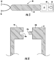
- Figures 5 and 6 show pin tweezer 40 intended for use in the inventive dental matrix system and, specifically, intended to provide electrical current to the dental matrix of Figures 1 and 2 .
- the pin tweezer 40 comprises a handle 42 and first and second pin end 44, 46 and compartment 48 in the handle 42 housing a power source 50 and voltage control circuitry 52 to regulate the electrical current being provided to the dental matrix 10.
- the power source 50 comprises a battery.
- the first and second pin ends 44, 46 are configured to electrically couple to the first and second electrodes 32, 36 of the dental matrix 10 ( Figure 1 ) to apply an electrical current across the OLED.
- Photoinitiators utilized in dental materials typically absorb light in the 400-500 nm range. Accordingly, the voltage control circuitry 52 will provide current to the OLED sufficient to generate light energy at this wavelength.
- first and second pin ends 44, 46 are configured to nest within each other when not in use and when the first pin end 44 is received by the second pin end 46, the interconnected pieces act as insulators when the pin tweezer 40 is not in use.
- the extension 44a on the first pin end 44 conducts electrical current while the remainder 44b of the first pin end 44 is comprised entirely of an insulating material or is coated in an insulating material.
- the extension 44a is received by receptacle 46a on the second pin end 46, the receptacle having sidewalls and a bottom.
- the receptacle 46a is dimensioned large enough to preclude extension 44a from contacting the sidewalls or bottom of the receptacle 46a when the extension inserts into the receptacle. Accordingly, when the receptacle 46a receives the extension 44a there is no electrical contact or electrical communication between the first and second pin ends 44, 46, the circuit is not closed and current from the power source will not flow through the first and second pin ends 44, 46.
- the PLED dental matrix system of the present invention works in the following manner:
Landscapes
- Health & Medical Sciences (AREA)
- Oral & Maxillofacial Surgery (AREA)
- Dentistry (AREA)
- Epidemiology (AREA)
- Life Sciences & Earth Sciences (AREA)
- Animal Behavior & Ethology (AREA)
- General Health & Medical Sciences (AREA)
- Public Health (AREA)
- Veterinary Medicine (AREA)
- Dental Tools And Instruments Or Auxiliary Dental Instruments (AREA)
- Dental Prosthetics (AREA)
- Electroluminescent Light Sources (AREA)
Description
- This invention relates generally to the field of dentistry and more specifically to dental matrix devices utilized in conjunction with fillings in the interproximal areas between adjacent teeth.
- Matrices and the use of matrix systems are well known and widely utilized in restorative dentistry. There are many types of matrices available. They are generally made entirely of metal or plastic and are sectional or circumferential bands.
-
US2007/0054233 andWO2014/210439 (a prior art document according to Art. 54(3) EPC) discloses prior art matrix systems. During the restoration of an inter-proximal cavity, the matrix band is secured around the tooth and cavity and forms a mold. This mold is filled with composite material and the composite is light cured. The difficulty with curing an inter-proximal restoration is that once the metal matrix band is wrapped around the tooth, the matrix band does not allow horizontal curing of the composite at the gingivo-proximal tooth surface. It has to be cured from above and this can lead to incomplete curing of the composite resin. When this occurs, composite resin can adhere to the metal matrix rather than the tooth and detach from the restoration when the matrix is removed. The restoration must then be re-done or repaired. - A polymer-based light emitting diode (PLED) is a device that consists of an electroluminescent conductive polymer sandwiched between an anode and a cathode on a substrate. An electrical voltage applied between the electrodes will cause the polymer to glow. These PLED devices are flexible and can be coated on metal surfaces.
- Prior art exists of metal matrices with one or two open areas covered with a membrane of transparent material and of matrices with illuminating ports with port covers. These open areas and ports cover a relatively large area of the matrix, They are also very thin and may result in restorations with poor anatomical form. Accordingly, one object of the present invention is to provide a means of effectively forming and light curing interproximal composite restorations. The device is a system that consists of a PLED dental matrix along with a pin-tweezer-type electrical connector.
- The present invention is defined in the
independent claims 1 and 3 with preferred embodiment defined in the dependent claims. The claimed invention, as described herein, provides the dentist with a means of firmly retaining the composite material within the inter-proximal or gingivo-proximal restoration with a metallic matrix. It also allows direct horizontal curing of composite material along with gingivo-proximal tooth surface. The dental matrix according to the present invention comprises (a) a metal matrix band comprising an internal surface and an external surface; and (b) an organic light emitting diode (OLED) layer disposed on at least a first portion of the internal surface of the metal matrix band, the OLED layer comprising a first electroluminescent polymer disposed between a first and a second electrode layer. The OLED layer may be a polymer-based light emitting diode (PLED) wherein the first electroluminescent layer is selected from the group consisting of poly (p-phenylene vinylene), polyfluorene, polyphenylene, and derivatives thereof. The second electrode may also cover substantially all of the internal surface of the dental matrix band or be arranged in a grid pattern and covers less than that all of the internal surface of the dental matrix band. The dental matrix band is a sectional matrix. - In another embodiment of the invention, the dental matrix band electrically couples with an electrified pin-tweezers to apply electrical current across the OLED. The pin tweezers comprises a first and second pin end that are electrical leads to couple with the first and second electrodes. The pin tweezers further comprises a handle with a compartment containing a power source and voltage control circuitry.
-
-
Figure 1 is an elevation view of a dental matrix band in accordance with the present invention. -
Figure 2 is an elevation view of a dental matrix band in accordance with the present invention. -
Figure 3 is a cross section view of a dental matrix, taken along line 3 - 3 inFigure 1 . -
Figure 4 is a cross section view of a dental matrix, taken along line 4 - 4 inFigure 1 . -
Figure 5 is an elevation view of a component of the inventive PLED dental matrix system. -
Figure 6 is a partial elevation view of the component of the inventive PLED dental matrix system shown inFigure 5 . -
Figures 1-5 show various embodiments and components of the present inventive dental matrix system. The embodiment ofFigures 1 and 2 show the basic form of adental matrix band 10, generally comprising amatrix body 12 having atop margin 14, opposingsides bottom margin 20. Atab 22 extends from thematrix body 12 at thetop margin 14 and include a through-hole 24. The matrix body has an internal andexternal surface 26, 28 (best seen inFigure 3 ). Theinternal surface 24 of thematrix body 12 is coated with an organic light emitting diode (OLED)layer 30. In these embodiments thematrix 10 is a circumferential matrix. - As seen in
Figure 3 , theOLED layer 30 comprises afirst electrode 32, namely the cathode, adjacent theinternal surface 24 of thematrix body 12 and anelectroluminescent layer 34 sandwiched between thefirst electrode 32 and asecond electrode 36, namely the anode. Theelectroluminescent layer 34 comprises anemissive layer 34a adjacent thefirst electrode 32 and aconductive layer 34b adjacent thesecond electrode 36. In these embodiments, theelectroluminescent layer 34 is comprised of a poly (p-phenylene vinylene) (PPV), a polyfluorene, and/or a polyphenylene or derivatives thereof. When theelectroluminescent layer 34 is comprised these materials the OLED is a polymer-based light emitting diode (PLED). A significant benefit of this configuration is the ability to provide curing light energy to dental restoration material directly from the interproximal space between adjacent teeth, providing a more consistent curing of the dental restoration materials as compared with the use of a handheld curing light alone. It is contemplated that the curing light energy generated by the inventive dental matrix can be supplemented through the use of a traditional curing light to expose the dental restoration material to light energy from the side and above the restoration area. -
Figures 1 and 2 also demonstrate alternativesecond electrode 36 configurations. InFigure 1 , thesecond electrode 36 is continuously coated as athin film 36a. InFigure 2 thesecond electrode 36 is in a partial grid pattern 36b to ensure the flow of electrons throughout thematrix body 12. Thesecond electrode 36 may remain fully exposed to avoid the need for a dedicated lead to electrically couple to a power source. In these embodiments the material selected for use as thesecond electrode 36 is transparent to enable the light energy generated by theelectroluminescent layer 34 to reach the light-curable dental restoration material. One of ordinary skill in the art will also understand to use transparent material for the cathode should the order of the cathode, anode and electroluminescent layer be reversed and the anode is thefirst electrode 32 adjacent to theinternal surface 24 of thematrix body 12. - Additional layers such as a second
luminescent layer 38a and secondelectron conducting layer 38b may also be present to improve the electron transport properties of LED.Figure 4 shows this configuration. -
Figures 5 and 6 show pin tweezer 40 intended for use in the inventive dental matrix system and, specifically, intended to provide electrical current to the dental matrix ofFigures 1 and 2 . Thepin tweezer 40 comprises ahandle 42 and first andsecond pin end compartment 48 in thehandle 42 housing apower source 50 andvoltage control circuitry 52 to regulate the electrical current being provided to thedental matrix 10. In this embodiment thepower source 50 comprises a battery. The first and second pin ends 44, 46 are configured to electrically couple to the first andsecond electrodes Figure 1 ) to apply an electrical current across the OLED. Photoinitiators utilized in dental materials typically absorb light in the 400-500 nm range. Accordingly, thevoltage control circuitry 52 will provide current to the OLED sufficient to generate light energy at this wavelength. - As seen in
Figure 6 , the first and second pin ends 44, 46 are configured to nest within each other when not in use and when thefirst pin end 44 is received by thesecond pin end 46, the interconnected pieces act as insulators when thepin tweezer 40 is not in use. Theextension 44a on thefirst pin end 44 conducts electrical current while theremainder 44b of thefirst pin end 44 is comprised entirely of an insulating material or is coated in an insulating material. Theextension 44a is received byreceptacle 46a on thesecond pin end 46, the receptacle having sidewalls and a bottom. Thereceptacle 46a is dimensioned large enough to precludeextension 44a from contacting the sidewalls or bottom of thereceptacle 46a when the extension inserts into the receptacle. Accordingly, when thereceptacle 46a receives theextension 44a there is no electrical contact or electrical communication between the first and second pin ends 44, 46, the circuit is not closed and current from the power source will not flow through the first and second pin ends 44, 46. - The PLED dental matrix system of the present invention works in the following manner:
- 1. The dentist prepares an inter-proximal cavity on the tooth surface ready to receive the light cured restoration material.
- 2. The PLED dental matrix is inserted into the inter-proximal space and held securely against the tooth with a retaining device.
- 3. To ensure there is no leaking of the composite between the matrix band and tooth, a dental wedge may be inserted into the inter-proximal space to hold the band firmly against the tooth surface.
- 4. The cavity is then filled with composite material.
- 5. The pin tweezer type connector is clamped to the PLED dental matrix and the current is switched on.
- 6. The PLED dental matrix produces light in the inter-proximal area.
- 7. The composite material is cured from the inter-proximal direction.
- 8. The composite material may also be cured using a curing light from the occlusal direction.
Claims (10)
- A dental matrix for use when filling inter-proximal cavities with a dental restorative material, the dental matrix comprising:(a) a metal matrix band (10) comprising an internal surface (24) and an external surface (26, 28); and(b) an organic light emitting diode (OLED) disposed on at least a first portion of the internal surface (24) of the metal matrix band (10), the OLED layer (30) comprising a first electroluminescent layer disposed between a first and a second electrode layer (32, 36).
- The dental matrix of Claim 1 wherein the OLED is a polymer-based light emitting diode (PLED); or wherein the second electrode is a continuous layer covering substantially all of the internal surface of the dental matrix band; or wherein the second electrode is arranged in a grid pattern and covers less than that all of the internal surface of the dental matrix band; or wherein the first electroluminescent layer is comprised of a first emissive layer and a first conductive layer and the first emissive and first conductive layers are comprised of material selected from the group consisting of poly (p-phenylene vinylene), polyfluorene, polyphenylene, and derivatives thereof; or wherein the second electrode is exposed; or wherein the matrix band is a sectional matrix; or wherein the first electroluminescent layer is comprised of a first emissive layer and a first conductive layer and the OLED further comprises a second emissive layer and a second conductive layer; or wherein the OLED is configured to generate light energy in the range of 400-500 nanometres.
- A dental matrix system for use when filling inter-proximal cavities with a light-cured dental restorative material, the dental matrix system comprising:(a) a dental matrix as defined in claim 1; and(b) a power source (50) comprising a first electrical lead configured to electrically couple to the first electrode of the OLED layer and a second lead configured to electrically couple to the second electrode of the OLED to apply electrical current to the dental matrix band (10) and activate the OLED layer.
- The dental matrix system of Claim 3 wherein the OLED is a polymer-based light emitting diode (PLED).
- The dental matrix system of Claim 3 wherein the power source comprises a pin tweezer with a first and second pin end wherein the first pin end comprises the first electrical lead and the second pin end comprises the second electrical lead.
- The dental matrix system of Claim 5 wherein the pin tweezer comprises a handle with a storage compartment configured to store the power source and a voltage control circuit.
- The dental matrix system of Claim 5 wherein the power source comprises a battery; or wherein the second electrode is fully exposed; or wherein the first electroluminescent layer is comprised of a first emissive layer and a first conductive layer and the OLED further comprises a second emissive layer and a second conductive layer; or wherein the power source is configured to apply electrical current across the OLED sufficient to generate light energy in the range of 400- 500 nanometres.
- The dental matrix system of Claim 5 wherein the first electrical lead of the first pin end is comprised of a first extension in the first pin end and the second pin end comprises a receptacle to receive the first extension, the receptacle having sidewalls and a bottom with a depth and width to receive the first extension and preclude contact of the first extension with the sidewalls or bottom.
- The dental matrix system of Claim 8 wherein the first pin end is comprised of an insulating material precluding electrical contact with the second pin end when the first extension of the first pin end is received by the receptacle on the second pin end.
- The dental matrix system of Claim 8 wherein the first pin end is covered with an insulating material precluding electrical contact of the first pin end with the second pin end when the first extension of the first pin end is received by the receptacle on the second pin end.
Applications Claiming Priority (2)
| Application Number | Priority Date | Filing Date | Title |
|---|---|---|---|
| NZ61747313 | 2013-11-07 | ||
| PCT/US2014/064692 WO2015070104A2 (en) | 2013-11-07 | 2014-11-07 | Pled dental matrix system |
Publications (2)
| Publication Number | Publication Date |
|---|---|
| EP3065666A2 EP3065666A2 (en) | 2016-09-14 |
| EP3065666B1 true EP3065666B1 (en) | 2018-03-21 |
Family
ID=52134339
Family Applications (1)
| Application Number | Title | Priority Date | Filing Date |
|---|---|---|---|
| EP14815956.9A Active EP3065666B1 (en) | 2013-11-07 | 2014-11-07 | Oled dental matrix system |
Country Status (5)
| Country | Link |
|---|---|
| US (1) | US20170231720A1 (en) |
| EP (1) | EP3065666B1 (en) |
| JP (1) | JP6777539B2 (en) |
| CA (1) | CA2929558C (en) |
| WO (1) | WO2015070104A2 (en) |
Families Citing this family (3)
| Publication number | Priority date | Publication date | Assignee | Title |
|---|---|---|---|---|
| JP1641373S (en) * | 2018-09-28 | 2019-09-17 | ||
| USD927695S1 (en) | 2019-03-27 | 2021-08-10 | Ultradent Products, Inc. | Dental matrix band |
| USD945625S1 (en) | 2019-09-30 | 2022-03-08 | Pinkband Dental Solutions, Inc. | Matrix band ring assembly for dental surgery |
Family Cites Families (14)
| Publication number | Priority date | Publication date | Assignee | Title |
|---|---|---|---|---|
| US4041952A (en) * | 1976-03-04 | 1977-08-16 | Valleylab, Inc. | Electrosurgical forceps |
| CH680563A5 (en) * | 1990-12-19 | 1992-09-30 | Weissenfluh Hawe Neos | |
| JPH0775643A (en) * | 1993-04-16 | 1995-03-20 | Yuichi Abe | Dental matrix band and clamp for fixing this band |
| US20070054233A1 (en) * | 2003-07-22 | 2007-03-08 | Biolase Technology, Inc. | Device for dental care and whitening |
| CN1449854A (en) * | 2002-04-08 | 2003-10-22 | 林亚夫 | Toy play set |
| JPWO2005055864A1 (en) * | 2003-12-15 | 2007-07-05 | 昭和薬品化工株式会社 | Oral light irradiation device |
| CN1895003A (en) * | 2003-12-30 | 2007-01-10 | 新加坡科技研究局 | Flexible electroluminescent component |
| EP1747595A1 (en) * | 2004-05-18 | 2007-01-31 | MERCK PATENT GmbH | Formulation for ink-jet printing comprising semiconducting polymers |
| US20080058907A1 (en) * | 2006-08-30 | 2008-03-06 | Reuben David I | Self Sanitizing Bandage with Built-In Ultraviolet LED |
| US20080064004A1 (en) * | 2006-09-13 | 2008-03-13 | Clark David J | Dental Kits And A Seamless, Single Load Cavity Preparation And Filling Technique |
| DE202007005626U1 (en) * | 2007-04-17 | 2007-06-28 | Villeroy & Boch Ag | WC seat with lid constructed on a support frame covered by veneer for a solid wood effect |
| JP5024021B2 (en) * | 2007-12-18 | 2012-09-12 | セイコーエプソン株式会社 | LIGHT EMITTING DEVICE AND ELECTRONIC DEVICE |
| DE102008054288A1 (en) * | 2008-11-03 | 2010-05-06 | Osram Gesellschaft mit beschränkter Haftung | Method for producing a flexible light strip |
| WO2014210439A1 (en) * | 2013-06-27 | 2014-12-31 | Dentsply International Inc. | Thin led film-based curing light system |
-
2014
- 2014-11-07 WO PCT/US2014/064692 patent/WO2015070104A2/en active Application Filing
- 2014-11-07 CA CA2929558A patent/CA2929558C/en active Active
- 2014-11-07 US US15/035,100 patent/US20170231720A1/en not_active Abandoned
- 2014-11-07 JP JP2016528109A patent/JP6777539B2/en active Active
- 2014-11-07 EP EP14815956.9A patent/EP3065666B1/en active Active
Also Published As
| Publication number | Publication date |
|---|---|
| WO2015070104A3 (en) | 2015-07-02 |
| JP2016537076A (en) | 2016-12-01 |
| CA2929558A1 (en) | 2015-05-14 |
| US20170231720A1 (en) | 2017-08-17 |
| WO2015070104A2 (en) | 2015-05-14 |
| CA2929558C (en) | 2021-06-29 |
| JP6777539B2 (en) | 2020-10-28 |
| EP3065666A2 (en) | 2016-09-14 |
Similar Documents
| Publication | Publication Date | Title |
|---|---|---|
| EP3065666B1 (en) | Oled dental matrix system | |
| US9209353B2 (en) | Low cost mounting of LEDs in TL-retrofit tubes | |
| US9472724B2 (en) | Semiconductor light emitting element | |
| ES2526076T3 (en) | Medical electrode with printed and shielded power supply conductor | |
| US7825583B2 (en) | Organic electroluminescence display and method for manufacturing the same | |
| WO2006125163A3 (en) | Implantable electrode assembly having reverse electrode configuration | |
| EP2187442A3 (en) | Light emitting device and light emitting device package having the same | |
| KR20080063794A (en) | A large area organic diode device and a method of manufacturing it | |
| EP2312659A3 (en) | Light emitting apparatus | |
| CN108430384B (en) | Thin flexible electric oral care device | |
| JP2003051384A5 (en) | ||
| WO2010107600A3 (en) | Resistively heated small planar filament | |
| JP2013546154A5 (en) | ||
| KR102321663B1 (en) | Lighting apparatus using organic light emitting diode and method of fabricating thereof | |
| US7857620B2 (en) | Toothbrush with an electric circuit | |
| EP2657996A3 (en) | Semiconductor light-emitting device | |
| KR20110122714A (en) | Electroluminescent device | |
| US20170354235A1 (en) | Curing applicator | |
| US20220338968A1 (en) | Method of Whitening Teeth | |
| WO2006041785A3 (en) | Ecg/pacing electrodes | |
| US8710732B2 (en) | Organic light emitting device connection methods | |
| WO2011073189A3 (en) | Large area light emitting device comprising organic light emitting diodes | |
| WO2017038655A1 (en) | Biocompatible light irradiation device, method for using biocompatible light irradiation device, sealing body for biocompatible light irradiation device, method for producing sealing body for biocompatible light irradiation device, method for using sealing body for biocompatible light irradiation device, set, skin disease treatment device, and beauty treatment device | |
| WO2018103614A1 (en) | Non-bracket led encapsulation structure and manufacturing method therefor | |
| EP3327807B1 (en) | Apparatus and method of fabricating lighting apparatus |
Legal Events
| Date | Code | Title | Description |
|---|---|---|---|
| PUAI | Public reference made under article 153(3) epc to a published international application that has entered the european phase |
Free format text: ORIGINAL CODE: 0009012 |
|
| 17P | Request for examination filed |
Effective date: 20160504 |
|
| AK | Designated contracting states |
Kind code of ref document: A2 Designated state(s): AL AT BE BG CH CY CZ DE DK EE ES FI FR GB GR HR HU IE IS IT LI LT LU LV MC MK MT NL NO PL PT RO RS SE SI SK SM TR |
|
| AX | Request for extension of the european patent |
Extension state: BA ME |
|
| DAX | Request for extension of the european patent (deleted) | ||
| REG | Reference to a national code |
Ref country code: DE Ref legal event code: R079 Ref document number: 602014022748 Country of ref document: DE Free format text: PREVIOUS MAIN CLASS: A61C0005120000 Ipc: A61C0005850000 |
|
| RIC1 | Information provided on ipc code assigned before grant |
Ipc: A61C 5/85 20170101AFI20170911BHEP Ipc: A61C 13/15 20060101ALI20170911BHEP |
|
| GRAP | Despatch of communication of intention to grant a patent |
Free format text: ORIGINAL CODE: EPIDOSNIGR1 |
|
| INTG | Intention to grant announced |
Effective date: 20171023 |
|
| RAP1 | Party data changed (applicant data changed or rights of an application transferred) |
Owner name: DENTSPLY SIRONA INC. |
|
| GRAS | Grant fee paid |
Free format text: ORIGINAL CODE: EPIDOSNIGR3 |
|
| GRAA | (expected) grant |
Free format text: ORIGINAL CODE: 0009210 |
|
| AK | Designated contracting states |
Kind code of ref document: B1 Designated state(s): AL AT BE BG CH CY CZ DE DK EE ES FI FR GB GR HR HU IE IS IT LI LT LU LV MC MK MT NL NO PL PT RO RS SE SI SK SM TR |
|
| REG | Reference to a national code |
Ref country code: GB Ref legal event code: FG4D |
|
| REG | Reference to a national code |
Ref country code: CH Ref legal event code: EP Ref country code: CH Ref legal event code: NV Representative=s name: E. BLUM AND CO. AG PATENT- UND MARKENANWAELTE , CH |
|
| REG | Reference to a national code |
Ref country code: SE Ref legal event code: TRGR |
|
| REG | Reference to a national code |
Ref country code: AT Ref legal event code: REF Ref document number: 980267 Country of ref document: AT Kind code of ref document: T Effective date: 20180415 |
|
| REG | Reference to a national code |
Ref country code: IE Ref legal event code: FG4D |
|
| REG | Reference to a national code |
Ref country code: DE Ref legal event code: R096 Ref document number: 602014022748 Country of ref document: DE |
|
| REG | Reference to a national code |
Ref country code: NL Ref legal event code: MP Effective date: 20180321 |
|
| PG25 | Lapsed in a contracting state [announced via postgrant information from national office to epo] |
Ref country code: NO Free format text: LAPSE BECAUSE OF FAILURE TO SUBMIT A TRANSLATION OF THE DESCRIPTION OR TO PAY THE FEE WITHIN THE PRESCRIBED TIME-LIMIT Effective date: 20180621 Ref country code: FI Free format text: LAPSE BECAUSE OF FAILURE TO SUBMIT A TRANSLATION OF THE DESCRIPTION OR TO PAY THE FEE WITHIN THE PRESCRIBED TIME-LIMIT Effective date: 20180321 Ref country code: CY Free format text: LAPSE BECAUSE OF FAILURE TO SUBMIT A TRANSLATION OF THE DESCRIPTION OR TO PAY THE FEE WITHIN THE PRESCRIBED TIME-LIMIT Effective date: 20180321 Ref country code: LT Free format text: LAPSE BECAUSE OF FAILURE TO SUBMIT A TRANSLATION OF THE DESCRIPTION OR TO PAY THE FEE WITHIN THE PRESCRIBED TIME-LIMIT Effective date: 20180321 Ref country code: HR Free format text: LAPSE BECAUSE OF FAILURE TO SUBMIT A TRANSLATION OF THE DESCRIPTION OR TO PAY THE FEE WITHIN THE PRESCRIBED TIME-LIMIT Effective date: 20180321 |
|
| REG | Reference to a national code |
Ref country code: LT Ref legal event code: MG4D |
|
| REG | Reference to a national code |
Ref country code: AT Ref legal event code: MK05 Ref document number: 980267 Country of ref document: AT Kind code of ref document: T Effective date: 20180321 |
|
| PG25 | Lapsed in a contracting state [announced via postgrant information from national office to epo] |
Ref country code: GR Free format text: LAPSE BECAUSE OF FAILURE TO SUBMIT A TRANSLATION OF THE DESCRIPTION OR TO PAY THE FEE WITHIN THE PRESCRIBED TIME-LIMIT Effective date: 20180622 Ref country code: BG Free format text: LAPSE BECAUSE OF FAILURE TO SUBMIT A TRANSLATION OF THE DESCRIPTION OR TO PAY THE FEE WITHIN THE PRESCRIBED TIME-LIMIT Effective date: 20180621 Ref country code: RS Free format text: LAPSE BECAUSE OF FAILURE TO SUBMIT A TRANSLATION OF THE DESCRIPTION OR TO PAY THE FEE WITHIN THE PRESCRIBED TIME-LIMIT Effective date: 20180321 Ref country code: LV Free format text: LAPSE BECAUSE OF FAILURE TO SUBMIT A TRANSLATION OF THE DESCRIPTION OR TO PAY THE FEE WITHIN THE PRESCRIBED TIME-LIMIT Effective date: 20180321 |
|
| REG | Reference to a national code |
Ref country code: FR Ref legal event code: PLFP Year of fee payment: 5 |
|
| PG25 | Lapsed in a contracting state [announced via postgrant information from national office to epo] |
Ref country code: NL Free format text: LAPSE BECAUSE OF FAILURE TO SUBMIT A TRANSLATION OF THE DESCRIPTION OR TO PAY THE FEE WITHIN THE PRESCRIBED TIME-LIMIT Effective date: 20180321 Ref country code: PL Free format text: LAPSE BECAUSE OF FAILURE TO SUBMIT A TRANSLATION OF THE DESCRIPTION OR TO PAY THE FEE WITHIN THE PRESCRIBED TIME-LIMIT Effective date: 20180321 Ref country code: EE Free format text: LAPSE BECAUSE OF FAILURE TO SUBMIT A TRANSLATION OF THE DESCRIPTION OR TO PAY THE FEE WITHIN THE PRESCRIBED TIME-LIMIT Effective date: 20180321 Ref country code: ES Free format text: LAPSE BECAUSE OF FAILURE TO SUBMIT A TRANSLATION OF THE DESCRIPTION OR TO PAY THE FEE WITHIN THE PRESCRIBED TIME-LIMIT Effective date: 20180321 Ref country code: RO Free format text: LAPSE BECAUSE OF FAILURE TO SUBMIT A TRANSLATION OF THE DESCRIPTION OR TO PAY THE FEE WITHIN THE PRESCRIBED TIME-LIMIT Effective date: 20180321 Ref country code: AL Free format text: LAPSE BECAUSE OF FAILURE TO SUBMIT A TRANSLATION OF THE DESCRIPTION OR TO PAY THE FEE WITHIN THE PRESCRIBED TIME-LIMIT Effective date: 20180321 |
|
| PG25 | Lapsed in a contracting state [announced via postgrant information from national office to epo] |
Ref country code: CZ Free format text: LAPSE BECAUSE OF FAILURE TO SUBMIT A TRANSLATION OF THE DESCRIPTION OR TO PAY THE FEE WITHIN THE PRESCRIBED TIME-LIMIT Effective date: 20180321 Ref country code: SK Free format text: LAPSE BECAUSE OF FAILURE TO SUBMIT A TRANSLATION OF THE DESCRIPTION OR TO PAY THE FEE WITHIN THE PRESCRIBED TIME-LIMIT Effective date: 20180321 Ref country code: SM Free format text: LAPSE BECAUSE OF FAILURE TO SUBMIT A TRANSLATION OF THE DESCRIPTION OR TO PAY THE FEE WITHIN THE PRESCRIBED TIME-LIMIT Effective date: 20180321 Ref country code: AT Free format text: LAPSE BECAUSE OF FAILURE TO SUBMIT A TRANSLATION OF THE DESCRIPTION OR TO PAY THE FEE WITHIN THE PRESCRIBED TIME-LIMIT Effective date: 20180321 |
|
| REG | Reference to a national code |
Ref country code: CH Ref legal event code: PK Free format text: BERICHTIGUNGEN |
|
| PG25 | Lapsed in a contracting state [announced via postgrant information from national office to epo] |
Ref country code: PT Free format text: LAPSE BECAUSE OF FAILURE TO SUBMIT A TRANSLATION OF THE DESCRIPTION OR TO PAY THE FEE WITHIN THE PRESCRIBED TIME-LIMIT Effective date: 20180723 |
|
| REG | Reference to a national code |
Ref country code: DE Ref legal event code: R097 Ref document number: 602014022748 Country of ref document: DE |
|
| RIC2 | Information provided on ipc code assigned after grant |
Ipc: A61C 5/85 20170101AFI20170911BHEP Ipc: A61C 13/15 20060101ALI20170911BHEP |
|
| PLBE | No opposition filed within time limit |
Free format text: ORIGINAL CODE: 0009261 |
|
| STAA | Information on the status of an ep patent application or granted ep patent |
Free format text: STATUS: NO OPPOSITION FILED WITHIN TIME LIMIT |
|
| PG25 | Lapsed in a contracting state [announced via postgrant information from national office to epo] |
Ref country code: DK Free format text: LAPSE BECAUSE OF FAILURE TO SUBMIT A TRANSLATION OF THE DESCRIPTION OR TO PAY THE FEE WITHIN THE PRESCRIBED TIME-LIMIT Effective date: 20180321 |
|
| REG | Reference to a national code |
Ref country code: CH Ref legal event code: PK Free format text: BERICHTIGUNGEN |
|
| RIC2 | Information provided on ipc code assigned after grant |
Ipc: A61C 13/15 20060101ALI20170911BHEP Ipc: A61C 5/85 20170101AFI20170911BHEP |
|
| 26N | No opposition filed |
Effective date: 20190102 |
|
| PG25 | Lapsed in a contracting state [announced via postgrant information from national office to epo] |
Ref country code: SI Free format text: LAPSE BECAUSE OF FAILURE TO SUBMIT A TRANSLATION OF THE DESCRIPTION OR TO PAY THE FEE WITHIN THE PRESCRIBED TIME-LIMIT Effective date: 20180321 |
|
| PG25 | Lapsed in a contracting state [announced via postgrant information from national office to epo] |
Ref country code: LU Free format text: LAPSE BECAUSE OF NON-PAYMENT OF DUE FEES Effective date: 20181107 Ref country code: MC Free format text: LAPSE BECAUSE OF FAILURE TO SUBMIT A TRANSLATION OF THE DESCRIPTION OR TO PAY THE FEE WITHIN THE PRESCRIBED TIME-LIMIT Effective date: 20180321 |
|
| REG | Reference to a national code |
Ref country code: BE Ref legal event code: MM Effective date: 20181130 |
|
| REG | Reference to a national code |
Ref country code: IE Ref legal event code: MM4A |
|
| PG25 | Lapsed in a contracting state [announced via postgrant information from national office to epo] |
Ref country code: IE Free format text: LAPSE BECAUSE OF NON-PAYMENT OF DUE FEES Effective date: 20181107 |
|
| PG25 | Lapsed in a contracting state [announced via postgrant information from national office to epo] |
Ref country code: BE Free format text: LAPSE BECAUSE OF NON-PAYMENT OF DUE FEES Effective date: 20181130 |
|
| PG25 | Lapsed in a contracting state [announced via postgrant information from national office to epo] |
Ref country code: MT Free format text: LAPSE BECAUSE OF NON-PAYMENT OF DUE FEES Effective date: 20181107 |
|
| PG25 | Lapsed in a contracting state [announced via postgrant information from national office to epo] |
Ref country code: TR Free format text: LAPSE BECAUSE OF FAILURE TO SUBMIT A TRANSLATION OF THE DESCRIPTION OR TO PAY THE FEE WITHIN THE PRESCRIBED TIME-LIMIT Effective date: 20180321 |
|
| PG25 | Lapsed in a contracting state [announced via postgrant information from national office to epo] |
Ref country code: HU Free format text: LAPSE BECAUSE OF FAILURE TO SUBMIT A TRANSLATION OF THE DESCRIPTION OR TO PAY THE FEE WITHIN THE PRESCRIBED TIME-LIMIT; INVALID AB INITIO Effective date: 20141107 Ref country code: MK Free format text: LAPSE BECAUSE OF NON-PAYMENT OF DUE FEES Effective date: 20180321 |
|
| PG25 | Lapsed in a contracting state [announced via postgrant information from national office to epo] |
Ref country code: IS Free format text: LAPSE BECAUSE OF FAILURE TO SUBMIT A TRANSLATION OF THE DESCRIPTION OR TO PAY THE FEE WITHIN THE PRESCRIBED TIME-LIMIT Effective date: 20180721 |
|
| P01 | Opt-out of the competence of the unified patent court (upc) registered |
Effective date: 20230509 |
|
| PGFP | Annual fee paid to national office [announced via postgrant information from national office to epo] |
Ref country code: FR Payment date: 20230929 Year of fee payment: 10 |
|
| PGFP | Annual fee paid to national office [announced via postgrant information from national office to epo] |
Ref country code: GB Payment date: 20231006 Year of fee payment: 10 |
|
| PGFP | Annual fee paid to national office [announced via postgrant information from national office to epo] |
Ref country code: SE Payment date: 20231002 Year of fee payment: 10 Ref country code: IT Payment date: 20231010 Year of fee payment: 10 Ref country code: DE Payment date: 20230929 Year of fee payment: 10 |
|
| PGFP | Annual fee paid to national office [announced via postgrant information from national office to epo] |
Ref country code: CH Payment date: 20240126 Year of fee payment: 10 |