EP3065470B1 - Procedure for selecting network discovery method - Google Patents
Procedure for selecting network discovery method Download PDFInfo
- Publication number
- EP3065470B1 EP3065470B1 EP16156224.4A EP16156224A EP3065470B1 EP 3065470 B1 EP3065470 B1 EP 3065470B1 EP 16156224 A EP16156224 A EP 16156224A EP 3065470 B1 EP3065470 B1 EP 3065470B1
- Authority
- EP
- European Patent Office
- Prior art keywords
- determined time
- time period
- discovery
- scanning
- frame
- Prior art date
- Legal status (The legal status is an assumption and is not a legal conclusion. Google has not performed a legal analysis and makes no representation as to the accuracy of the status listed.)
- Active
Links
- 238000000034 method Methods 0.000 title claims description 101
- 230000005540 biological transmission Effects 0.000 claims description 51
- 238000004590 computer program Methods 0.000 claims description 19
- 230000008569 process Effects 0.000 claims description 14
- 108091006146 Channels Proteins 0.000 description 130
- 230000007704 transition Effects 0.000 description 28
- 238000004891 communication Methods 0.000 description 24
- 230000004044 response Effects 0.000 description 15
- 239000000523 sample Substances 0.000 description 13
- 230000006870 function Effects 0.000 description 11
- 238000001514 detection method Methods 0.000 description 9
- 238000010586 diagram Methods 0.000 description 9
- 230000011664 signaling Effects 0.000 description 9
- 230000000694 effects Effects 0.000 description 8
- 230000001960 triggered effect Effects 0.000 description 7
- 238000012545 processing Methods 0.000 description 5
- 230000007246 mechanism Effects 0.000 description 4
- VYLDEYYOISNGST-UHFFFAOYSA-N bissulfosuccinimidyl suberate Chemical compound O=C1C(S(=O)(=O)O)CC(=O)N1OC(=O)CCCCCCC(=O)ON1C(=O)C(S(O)(=O)=O)CC1=O VYLDEYYOISNGST-UHFFFAOYSA-N 0.000 description 3
- 230000010267 cellular communication Effects 0.000 description 2
- 230000001149 cognitive effect Effects 0.000 description 2
- 238000011161 development Methods 0.000 description 2
- 238000007726 management method Methods 0.000 description 2
- 101100172132 Mus musculus Eif3a gene Proteins 0.000 description 1
- 239000000872 buffer Substances 0.000 description 1
- 239000000969 carrier Substances 0.000 description 1
- 230000001413 cellular effect Effects 0.000 description 1
- 238000013500 data storage Methods 0.000 description 1
- 230000001419 dependent effect Effects 0.000 description 1
- 238000013461 design Methods 0.000 description 1
- 238000005516 engineering process Methods 0.000 description 1
- 238000000605 extraction Methods 0.000 description 1
- 230000014509 gene expression Effects 0.000 description 1
- 230000000977 initiatory effect Effects 0.000 description 1
- 230000003993 interaction Effects 0.000 description 1
- 230000007774 longterm Effects 0.000 description 1
- 238000000638 solvent extraction Methods 0.000 description 1
- 238000012546 transfer Methods 0.000 description 1
Images


Classifications
-
- H—ELECTRICITY
- H04—ELECTRIC COMMUNICATION TECHNIQUE
- H04W—WIRELESS COMMUNICATION NETWORKS
- H04W48/00—Access restriction; Network selection; Access point selection
- H04W48/16—Discovering, processing access restriction or access information
-
- H—ELECTRICITY
- H04—ELECTRIC COMMUNICATION TECHNIQUE
- H04W—WIRELESS COMMUNICATION NETWORKS
- H04W74/00—Wireless channel access, e.g. scheduled or random access
- H04W74/08—Non-scheduled or contention based access, e.g. random access, ALOHA, CSMA [Carrier Sense Multiple Access]
- H04W74/0808—Non-scheduled or contention based access, e.g. random access, ALOHA, CSMA [Carrier Sense Multiple Access] using carrier sensing, e.g. as in CSMA
- H04W74/0816—Non-scheduled or contention based access, e.g. random access, ALOHA, CSMA [Carrier Sense Multiple Access] using carrier sensing, e.g. as in CSMA carrier sensing with collision avoidance
-
- H—ELECTRICITY
- H04—ELECTRIC COMMUNICATION TECHNIQUE
- H04W—WIRELESS COMMUNICATION NETWORKS
- H04W84/00—Network topologies
- H04W84/02—Hierarchically pre-organised networks, e.g. paging networks, cellular networks, WLAN [Wireless Local Area Network] or WLL [Wireless Local Loop]
- H04W84/10—Small scale networks; Flat hierarchical networks
- H04W84/12—WLAN [Wireless Local Area Networks]
Definitions
- the invention relates to the field of wireless communications and, particularly, to scanning for a wireless network in a wireless device.
- a wireless device supporting a wireless communication protocol may be configured to scan for available communication channels before initiating a link setup with an access node or another terminal device of a wireless network.
- the scanning may comprise passive scanning in which the terminal device scans for broadcast messages or active scanning in which the terminal device transmits a scanning request message and receives a response to the scanning request message.
- US 2014/016511 discloses a method for reducing the time and power consumption for stations to scan for wireless network coverage and establish a link to the responder to gain access thereto.
- a first scan phase establishing the existence and perhaps other characteristics of responders, is followed by an responder discovery phase where a link can be established using active or passive scanning procedures.
- the two phases are somewhat combined with the first phase using a Probe Request with an Organizationally Unique Identifier as the Scan Request and an ACK message acting as a Scan Request Response and a Probe Response Request transmitted separately.
- Specific timings and message constructs allow utilization within existing or new 802.11 standards.
- US 2011/045771 discloses a method, a personal area network device operating as a slave, and a short range communications device operating as a slave.
- a data storage may store at least one protocol-specific channel criterion for a connection with a master short range communication device.
- a short range transceiver may execute a preliminary device scan of a scanning set of communication channels for radio frequency energy.
- a processor may decide to execute a full device scan based in part on the protocol-specific channel criterion.
- FIG 1 illustrates wireless communication devices comprising a plurality of access points (AP) 100, 102 and a plurality of wireless terminal devices (STA) 110, 112, 114.
- Each base station may be associated with a basic service set (BSS) which is a basic building block of an IEEE 802.11 wireless local area network (WLAN).
- BSS basic service set
- the most common BSS type is an infrastructure BSS that includes a single AP together with all STAs associated with the AP.
- the AP may be a fixed AP or it may be a mobile AP.
- the APs 100, 102 may also provide access to other networks, e.g. the Internet.
- the BSS may comprise a plurality of APs to form an extended service set (ESS).
- ESS extended service set
- IEEE 802.11n specification specifies a data transmission mode that includes 20 megahertz (MHz) wide primary and secondary channels.
- the primary channel is used in all data transmissions with clients supporting only the 20 MHz mode and with clients supporting higher bandwidths.
- a further definition in 802.11n is that the primary and secondary channels are adjacent.
- the 802.11n specification also defines a mode in which a STA may, in addition to the primary channel, occupy one secondary channel which results in a maximum bandwidth of 40 MHz.
- IEEE 802.11ac task group extends such an operation model to provide for wider bandwidths by increasing the number of secondary channels from 1 up to 7, thus resulting in bandwidths of 20 MHz, 40 MHz, 80 MHz, and 160 MHz.
- a 40 MHz transmission band may be formed by two contiguous 20 MHz bands, and an 80 MHz transmission band may be formed by two contiguous 40 MHz bands. However, a 160 MHz band may be formed by two contiguous or non-contiguous 80 MHz bands.
- the transmission band of a BSS contains the primary channel and zero or more secondary channels.
- the secondary channels may be used to increase data transfer capacity of a transmission opportunity (TXOP).
- the secondary channels may be called a secondary channel, a tertiary channel, a quaternary channel, etc. However, let us for the sake of simplicity use the secondary channel as the common term to refer also to the tertiary or quaternary channel, etc.
- the primary channel may be used for channel contention, and a TXOP may be gained after successful channel contention on the primary channel.
- Some IEEE 802.11 networks are based on carrier sense multiple access with collision avoidance (CSMA/CA) for channel access.
- CSMA/CA carrier sense multiple access with collision avoidance
- Some networks may employ enhanced distributed channel access (EDCA) which provides quality-of-service (QoS) enhancements to medium access control (MAC) layer.
- QoS enhancements may be realized by providing a plurality of access categories (AC) for prioritizing frame transmissions.
- the access categories may comprise the following priority levels in the order of increasing priority: background (AC_BK), best effort (AC_BE), video streaming (AC_VI), and voice (AC_VO).
- a higher priority frame transmission may use a shorter contention window and a shorter arbitration inter-frame spacing (AIFS) that result in higher probability of gaining the TXOP.
- AIFS arbitration inter-frame spacing
- some networks may employ restricted access windows (RAW) where a reduced set of wireless devices of the wireless network may carry out channel contention.
- the access node may define the RAW and a group of wireless devices that are allowed to attempt the channel access within the RAW.
- Grouping allows partitioning of the wireless devices into groups and restricting channel access only to wireless devices belonging to a specified group at any given time period. The time period may be enabled by allocating slot duration and a number of slots in RAW access.
- the grouping may help to reduce contention by restricting access to the medium only to a subset of the wireless devices.
- the grouping may also reduce the signalling overhead.
- the STA may carry out the CCA procedure in order to determine whether the channel is free or busy. Upon detecting radio energy that exceeds a preset threshold on the channel, the STA may determine that the channel is busy and prevent the transmission. On the other hand, if the STA detects no radio energy exceeding the threshold on the channel during the determined time period, it may carry out the transmission.
- the STA may use a single threshold in the CCA procedure but, in some embodiments, a plurality of thresholds and frame detection are applied. Upon detecting a transmission on the channel, the STA may determine whether the on-going transmission is a frame header or frame payload portion.
- the STA may determine a threshold for use with the detected transmission. For example, a first threshold may be applied to the frame header while a second, different threshold may be applied to the frame payload portion.
- the first threshold may be denoted by a carrier sensing header threshold
- the second threshold may be denoted by a carrier sensing data unit threshold.
- the carrier sensing data unit threshold may be -62 decibels with respect to one milliwatt (dBm), while the carrier sensing header threshold may be -82 dBm. Accordingly, the STA may be more sensitive with respect to frame headers than with respect to frame payload portions. This ensures that the headers will less likely collide with other impending transmissions, while spatial reuse of the channel is encouraged for payload portions.
- a virtual carrier sensing function is provided by the provision of a network allocation vector (NAV) which is used to reserve a channel for the duration of the TXOP.
- NAV network allocation vector
- Most of the transmitted frames comprise a duration field which can be used to reserve the medium, or provide duration of the NAV protection, for the duration indicated by the value of the duration field.
- the NAV is a timer that indicates the amount of time the medium will be reserved.
- the transmitting station (STA) will set the value of the duration field according to the time for which it expects to use the medium while all receiving STAs, except the intended receiver, update their NAV appropriately with the information in the duration field and count down from the NAV to zero before starting the channel contention.
- the virtual carrier sensing function indicates that the medium is busy when NAV is non-zero and idle when NAV is zero.
- the NAV may be set to protect frame transmissions.
- the communication devices obtain the NAV on the primary channel of the BSS.
- the BSS may be represented by the access node and one or more terminal devices connected to the access node.
- the access node 100 and the terminal devices 112, 114 may be comprised in the first BSS and, thus, in the same wireless network while other terminal devices and access nodes (not shown) may be comprised in a second BSS which may be a neighbour to the first BSS and an OBSS with respect to the first BSS.
- the first BSS and the second BSS may be overlapping BSSs in the sense that at least some of the devices first BSS are capable of receiving frames from the second BSS and vice versa.
- the wireless network may comprise a single BSS or a plurality of BSSs.
- the wireless network may comprise a plurality of BSSs that have the same service set identifier (SSID) the same roaming identifier, and/or the same roaming partnership.
- SSID service set identifier
- a terminal device may establish a connection with any one of the access nodes it has detected to provide a wireless connection within the neighbourhood of the terminal device.
- the connection establishment may include authentication in which an identity of the terminal device is established in the access node.
- the authentication may comprise exchanging an encryption key used in the BSS.
- the access node and the terminal device may carry out association in which the terminal device is fully registered in the BSS, e.g. by providing the terminal device with an association identifier (AID).
- AID association identifier
- association of the terminal device to an access node should be understood broadly as establishing a connection between the terminal device and the access node such that the terminal device is in a connected state with respect to the access node and scanning for downlink frame transmissions from the access node and its own buffers for uplink frame transmissions.
- the terminal device 110 located in a coverage area 122 of the access node 102 may associate to the access node 102, and the terminal device 114 located in both coverage areas 120, 122 may associate to either access node 100, 102.
- the terminal devices 110 to 114 may discover the access nodes 100, 102 through a network discovery process.
- IEEE 802.11ai task group defines principles for fast initial link setup (FILS).
- One aspect of the principles is to enable faster and more precise AP and network discovery.
- Some principles relate to passive scanning in which a scanning device, e.g. a STA, passively scans channels for any beacon, management, or advertisement frames.
- Other principles relate to active scanning in which the scanning device actively transmits a scanning request message, e.g. a Probe Request message or a generic advertisement service (GAS) request, in order to query for present APs or networks.
- the probe request may also set some conditions that a responding device should fulfil in order to respond to the probe request.
- the scanning device may be called a requesting device or a requesting apparatus. Responding devices may transmit scanning response messages, e.g.
- Probe Response messages in response to the scanning request message, wherein the scanning response message may contain information on the responding device, its network, and other networks.
- the responding device may also send unsolicited probe response messages.
- Embodiments of the scanning enhancements described herein encompass the network discovery signalling, probe request-response processes, as well as GAS request-response processes.
- Optimized Connectivity Experience in Wi-Fi Alliance (WFA) is a program which has been charted to define mechanisms that improve the connectivity experience by utilizing information available in planned and managed networks.
- OCE is adding new network discovery mechanisms one of which may be called a dense deployment discovery mode for OCE-capable devices.
- the new discovery mechanism aims to reduce signaling overheads.
- the target is that the OCE-capable terminal device would discover the available OCE-capable access nodes by using only passive scanning and the terminal device would not need to perform other scanning operations after the initial passive scanning, at least in most scenarios.
- it would be advantageous if the terminal devices are able to detect access nodes that are not OCE-capable (so-called legacy access nodes).
- the legacy access nodes may transmit a beacon with 100ms (milliseconds) periodicity, while the OCE-capable access nodes enhance the passive scanning by transmitting additional FILS Discovery frames between Beacon frames.
- the FILS Discovery frames are transmitted once every 20 ms. Accordingly, it may be assumed that an OCE-capable terminal device discovers an OCE-capable access node relatively fast without additional signaling from OCE-capable terminal device.
- the active scanning associated with the legacy access nodes may cause signaling overhead, particularly in dense deployment scenarios.
- an effective selection logic is needed for an apparatus supporting both active scanning and passive scanning. If the terminal device selects the passive scanning method in a situation where there are no OCE-capable access nodes present, the detection of a legacy access node is time-consuming. On the other hand, if the terminal device selects the active scanning method in a situation where there is an OCE-capable access node present, the terminal device may cause additional signaling overhead with the transmitted scanning requests.
- the terminal device When the terminal device initiates the active scanning, it starts competing on the channel after a probe delay, or after it has detected transmission from other device.
- the target of this operation is to ensure that the scanning device has obtained NAV value and does not collide with an ongoing transmission.
- the scanning device After obtaining access to the channel, the scanning device sends a scanning request frame and waits for an access node to respond with a scanning response frame.
- the terminal device may wait for a transmission of a discovery frame from an access node.
- Figure 2 illustrates a signalling diagram of a method for selecting a network discovery method in an apparatus according to an embodiment of the invention.
- the apparatus may be a terminal device, e.g. a terminal device 110, 112, or 114.
- the method comprises in the apparatus: performing, by an apparatus, initial channel assessment of a radio channel at maximum a determined time period shorter than or equal to the shortest of a plurality of discovery frame broadcast periodicities employed by access nodes the apparatus is configured to search for in network discovery (block 200); upon determining that a transmission has been detected in the initial channel assessment (YES in block 202), selecting in the apparatus a network discovery according to a first network discovery method (block 204); and upon detecting no transmission on the radio channel during the initial channel assessment (NO in block 202), selecting in the apparatus network discovery according to a second network discovery method different from the first network discovery method (block 206).
- the determined time period is equal to the shortest of the plurality of discovery frame broadcast periodicities.
- the embodiment of Figure 2 may employ in the initial channel assessment an estimate of channel utilization as a criterion for the selection of the network discovery method, e.g. the passive scanning or the active scanning.
- the apparatus may determine that the channel is densely utilized and choose the first network discovery method employing the passive scanning only. Accordingly, the apparatus will not congest the channel with unnecessary scanning requests in a situation where the channel is densely utilized. Additionally, the apparatus may reduce power consumption by preventing unnecessary active scanning.
- the apparatus may determine that the channel is not utilized densely and select the network discovery method employing the second network discovery method employing active scanning or, in another embodiment, select a network discovery method enabling both active and passive scanning functions. Accordingly, the apparatus may speed up discovery of a network in a situation where the channel is not utilized densely by enabling the active scanning.
- both network discovery methods may employ both active scanning and the passive scanning but the first network discovery method may specify different rules for the active scanning than the second network discovery method.
- the result of the rules may be that the apparatus employing the first network discovery method transmits the scanning messages less often than the apparatus employing the second network discovery method.
- the first network discovery method may specify, for example, restrictions to the transmission timing of the scanning request messages, while the second network discovery method specifies no such restrictions.
- the terminal device may be configured to search for access nodes that transmit discovery frames with a higher periodicity (higher frequency), e.g. with 20ms periodicity, and access nodes that transmit the discovery frames with a lower periodicity (lower frequency), e.g. 100ms periodicity. Accordingly, the duration of the initial channel assessment may be shorter than the periodicity of said higher periodicity.
- the apparatus has performed the initial channel assessment before the execution of the procedure of Figure 2 .
- the initial channel assessment may have been made as a part of conventional channel access by the apparatus. Any time the apparatus performs channel scanning in an attempt to access the channel for frame transmissions or in an attempt to detect transmissions by other apparatuses, the apparatus may store a record of a detected frame transmission or, in general, a record of detected transmission on the channel.
- the apparatus may store in the record an identifier of the channel and at least one of the following information: the location where the discovery was performed such as satellite positioning coordinates or an identifier of a cell of a cellular communication system; information on the channel obtained from at least one other channel; an identifier of a discovered access node or a wireless network and capability of the access node or the wireless network to support only the passive scanning; a value indicating the amount of traffic on the channel; a time label indicating the timing of the latest update of the record.
- the apparatus may initiate the initial channel assessment.
- the apparatus employs a timer to define the duration of the initial channel assessment.
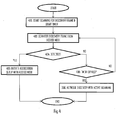
- Figure 3 illustrates a flow diagram of such an embodiment of Figure 2 . Referring to Figure 3 , the apparatus starts the initial channel assessment in block 300. At the same time, the apparatus may start a timer counting a time period allocated to the initial channel assessment.
- the time period counted by the timer is shorter than or equal to a discovery frame broadcast interval of an access node supporting the passive scanning only, e.g. an OCE-capable access node.
- the time period may be shorter than or equal to 20 milliseconds (ms) which is the periodicity of the FILS discovery frames.
- the time period may be shorter than or equal to 10ms.
- the time period may be shorter than or equal to 5ms.
- the apparatus may scan for radio energy on the radio channel (block 302).
- the radio channel may be a 2.4 GHz channel the apparatus knows to be used by OCE-capable access nodes, or it may be another channel the apparatus knows to be a potential operating channel of an access node to which the apparatus may associate.
- the apparatus may gain information on the potential operating channels from previous network discovery attempts, from information received from a cellular communication network through an access network discovery and selection function (ANDSF) specified within 3GPP (3 rd Generation Partnership Project).
- Block 302 may comprise or consist of physical carrier sensing.
- the process may proceed to block 304 in which the carrier sensing is performed until the timer expires.
- the apparatus may assume that there is no dense utilization of the radio channel and select second network discovery method employing the active scanning (block 306).
- the apparatus may switch from the passive scanning to the active scanning.
- Figure 4 illustrates an embodiment of the operation of the apparatus in a situation where the apparatus has selected the passive scanning in block 204. Referring to Figure 4 , the apparatus starts the passive scanning in block 400 and starts a timer counting a determined time interval.
- the time interval may be longer than the time period described above in connection with Figure 3 . In an embodiment, the time interval is shorter than or equal to a discovery frame broadcast interval of an access node supporting the first network discovery method. In an embodiment, the time interval is 10ms.
- the combined duration of the time period of the initial channel assessment and the time interval specifying the duration of the passive scanning after its selection is shorter than the shortest of the plurality discovery frame broadcast periodicities employed by access nodes the apparatus is configured to search for in the network discovery, e.g. shorter than the periodicity of the FILS discovery frames.
- the combined duration of the time period and the time interval is 15ms.
- the apparatus scans for discovery frames transmitted by access nodes, e.g. OCE-capable access nodes and/or the legacy access nodes.
- the discovery frames may comprise beacon frames, FILS discovery frames, etc.
- the process may proceed to block 406 in which the apparatus may determine that it is capable of associating to the access node, and the apparatus may initiate association to the access node.
- the passive scanning for the discovery frames may be continued until the timer is detected to have expired (block 408).
- the apparatus may switch to the active scanning (block 306) and, in an embodiment, cause transmission of a scanning request message such as a probe request message.
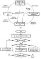
- Figure 5 illustrates a state transition diagram of the apparatus in connection with selecting the network discovery method according to an embodiment of the invention.
- Figure 5 illustrates four different states 500, 502, 504, 506 and events causing the switch from one state to another.
- the apparatus performs the initial channel assessment by performing physical carrier sensing according to the embodiment of Figure 3 , for example.
- the apparatus performs the network discovery employing passive scanning functions or active scanning functions such that the use of the active scanning is restricted.
- the apparatus may be configured to provide at least a minimum delay between transmissions of consecutive scanning request messages. The delay may be 20ms, for example..
- the apparatus performs active passive scanning functions with the option of using also passive scanning.
- the apparatus may freely choose to use either passive scanning or the active scanning at any time instant.
- the apparatus performs channel assessment according to the passive scanning.
- State 506 may be performed according to the embodiment of Figure 4 , e.g. by employing the passive scanning for the determined time interval.
- the state 506 may be considered as a temporary or a short-term passive scanning state.
- the difference between state 500 and state 506 may be that the state 500 is based only on carrier sensing while the apparatus is configured to detect received frames and extract relevant network discovery information from the received frames.
- the received frames may comprise at least one of beacon frames, probe response frames transmitted by an access node to another apparatus, and FILS discovery frames.
- the relevant information may comprise any information element used exclusively by an access node supporting the passive scanning functions only or an information element indicating that an access node transmitting the frame supports the passive scanning functions only.
- Such an information element may be an OCE-specific information element such as an information element indicating that a transmitter of the frame supports the OCE.
- the apparatus may perform the initial channel assessment in state 500.
- the initial channel assessment may also be used if the information is determined to be outdated due to the time passed from the previous network discovery attempt, or the apparatus has moved a determined distance from the location where the previous network discovery attempt was made, or according to another criterion.
- the state 500 may be entered from the state 502 or 504 when the apparatus determines that a new initial channel assessment is needed.
- the transition from the state 500 to the state 506 may be triggered upon detecting activity on the channel being assessed.
- the detection may be performed by employing the physical carrier sensing during the above-mentioned time period associated with the duration of the initial channel assessment. If radio energy having reception signal strength exceeding a determined threshold is detected in the state 500, the transition to the state 506 may be triggered. Upon detecting no activity, e.g. no radio energy exceeding the threshold in the state 500, the state transition to state 504 may be triggered.
- the apparatus attempts to detect a discovery frame according to the passive scanning. Upon detecting such a discovery frame, e.g. within the above-described time interval, the apparatus may trigger state transition to the state 502. On the other hand, upon detecting no discovery frame, e.g. within the above-described time interval, the apparatus may trigger the state transition to the state 504.
- State 504 may be called a legacy discovery mode referring to that it may be designed for detecting the legacy access nodes broadcasting the discovery frames with the lower periodicity.
- State 502 may be called an OCE discovery mode referring to that it may be designed for detecting the OCE-capable access nodes broadcasting the discovery frames with the higher periodicity.
- the apparatus may trigger state transition to the state 502 in which the active scanning is more restricted.
- the apparatus may trigger transition to the state 500.
- the apparatus may trigger transition to the state 500.
- the apparatus may trigger state transition from the state 506 to the state 504 upon detecting no discovery frame within a determined time duration.
- the time duration may be longer than the above-described time period and/or the time interval, e.g. 100ms. As a consequence, the free use of the active scanning methods become available to the apparatus.
- the apparatus may start the state machine from the state 504 in case that it knows that no access node transmitting the discovery frames with the higher periodicity is operating on the channel.
- the apparatus may start from the state 502 in a case where the apparatus knows that an access node transmitting the discovery frames with the higher periodicity is operating on the channel.
- the apparatus may employ the active scanning in both states 502 and 504.
- the apparatus when the apparatus employs the active scanning in the state 504, the apparatus generates a scanning request message that complies with specifications of the legacy access nodes, e.g. it contains no OCE-specific information elements.
- the apparatus when the apparatus employs the active scanning in the state 504, the apparatus generates a scanning request message that complies with specifications of the OCE-capable access nodes, e.g. it contains no OCE-specific information elements.
- the apparatus may in state 502 generate the scanning request message that complies with specifications of the OCE-capable access nodes, e.g. it contains no OCE-specific information elements.
- the apparatus may store a record of scanned channels and the information on availability of the wireless networks on the scanned channels and a network discovery method of the wireless networks detected on the scanned channels. This speeds up the process of finding a wireless network.
- an OCE-capable terminal device may be configured to detect also the legacy access nodes.
- the OCE-capable terminal device may implement additionally a discovery mechanism which is designed to discover efficiently such legacy networks.
- the terminal device may implement two network discovery methods: a first network discovery method to discover the OCE-capable access nodes and a second network discovery method to discover the legacy access nodes. Both discovery methods may employ both active scanning where the terminal device sends actively frames to discover access nodes and passive scanning where the terminal device listens for the discovery frames from the access nodes.
- the first network discovery method may specify certain rules for transmitting active scanning messages, while the second network discovery method may provide more relaxed rules or even no rules for the transmitting the active scanning messages.
- the first network discovery method may specify a certain minimum time interval between two consecutive scanning messages transmitted by the terminal device, while the second network discovery method specifies no restrictions to the periodicity or time interval between the two consecutive scanning messages.
- the initial channel assessment is performed by using carrier sensing and determining whether or not radio energy interpreted as a transmission is detected on the channel.
- Figure 6 illustrates another embodiment where the apparatus may also employ frame detection and decoding in the initial channel assessment and in the detection of the transmissions.
- the apparatus may perform the initial channel assessment in block 600 by employing passive scanning for a determined duration X, wherein the determined duration may be the above-described time period. X may be any one of the above-described values, e.g. 5ms.
- the passive scanning may comprise the carrier sensing and frame decoding functions.
- the process may proceed to block 406 in which the apparatus may establish an association with an access node that transmitted the discovery frame. If no discovery frame has been successfully decoded within the duration X, the apparatus determines in block 606 whether or not another type of transmission has been detected. The determination may be based on the carrier sensing and/or frame detection. The determination may comprise determining whether or not radio energy exceeding a determined threshold has been detected and/or whether or not a frame other than the discovery frame has been detected. If a result of block 606 is that the transmission has been detected, the apparatus may proceed with the network discovery by employing passive scanning for a determined duration Y in block 610.
- a discovery frame such as a FILS discovery frame, a beacon frame, and a probe response frame
- the passive scanning in block 610 may comprise frame detection and decoding.
- the duration Y may be the above-described time interval. If a discovery frame has been detected within the duration Y (YES in block 612), the apparatus may proceed to block 406. If no transmission is detected in block 606 or no discovery frame is detected in block 612, the apparatus may proceed to block 306 and initiate the second network discovery method by causing transmission of a scanning request message.
- the first network discovery method may comprise the block 610, while the second network discovery method may comprise the block 306.
- Figure 7 illustrates a state diagram corresponding to yet another embodiment.
- state 700 may correspond to block 600, e.g. the apparatus may perform the initial channel assessment by employing the frame decoding and the carrier sensing for the duration X in the state 700.
- state 706 may correspond to the block 610, and the apparatus may perform the passive scanning including the frame decoding for the duration Y in the state 706.
- State 702 may comprise performing passive scanning, and state 704 may comprise performing active scanning.
- the apparatus may perform the initial channel assessment in state 700.
- the initial channel assessment may also be used if the information is determined to be outdated due to the time passed from the previous network discovery attempt, or according to another criterion, e.g. one of the criteria described above in connection with Figure 5 .
- the state 700 may be entered from the state 702 or 704 when the apparatus determines that a new initial channel assessment is needed. Transition from the state 700 to the state 702 may be triggered upon detecting a discovery frame. The detection may be based on successful decoding and identification of the discovery frame.
- the apparatus may in the state employ the passive scanning or only the passive scanning whenever it determines to perform network discovery.
- the transition from the state 700 to the state 706 may be triggered upon detecting no discovery frame but another transmission, in general activity, on the channel being assessed.
- the detection may be performed by employing the physical carrier sensing during the above-mentioned time period associated with the duration of the initial channel assessment. If radio energy having reception signal strength exceeding a determined threshold is detected in the state 700, the transition to the state 706 may be triggered.
- no activity e.g. no radio energy exceeding the threshold in the state 700, the state transition to state 704 may be triggered.
- the apparatus attempts to detect a discovery frame by employing the passive scanning for the duration Y. Upon detecting such a discovery frame, e.g. within the above-described time interval, the apparatus may trigger state transition to the state 702. On the other hand, upon detecting no discovery frame, e.g. within the above-described time interval, the apparatus may trigger the state transition to the state 704.
- the apparatus attempts to discover a wireless network by employing the active scanning methods or both passive and active scanning methods.
- the apparatus may trigger state transition to the state 702 in which only the passive scanning is employed.
- the apparatus may trigger transition to the state 700.
- the apparatus may trigger transition to the state 700.
- a network discovery method is selected for a channel being scanned.
- the network discovery method may specify according to the description above which type of scanning (active or passive) is available and, in some embodiments, under which conditions. The selection may be made between the active and the passive scanning as the network discovery method or between the above-described legacy discovery mode and the OCE discovery mode specifying different conditions for the transmission of the scanning request messages.
- the apparatus may select the network discovery method per channel and store a record comprising a network discovery method selected for each scanned channel. Later on, upon returning to the channel, the apparatus may check the record and select the previously selected network discovery method without the need for performing the initial channel assessment again. When the record for a channel is considered to be outdated, a new initial channel assessment may be carried out, as described above, and the record may be updated.
- Figure 8 illustrates an embodiment of a structure of the above-mentioned functionalities of the apparatus, wherein the apparatus may be a terminal device, user equipment, a peer device, or a client device.
- the apparatus may comply with specifications of an IEEE 802.11 network and/or another wireless network.
- the apparatus may be defined as a cognitive radio apparatus capable of adapting its operation to a changing radio environment, e.g. to changes in parameters of another system on the same frequency band.
- the apparatus may be or may be comprised in a computer (PC), a laptop, a tablet computer, a cellular phone, a palm computer, or any other apparatus provided with radio communication capability.
- the apparatus carrying out the above-described functionalities is comprised in such a device, e.g. the apparatus may comprise a circuitry, e.g. a chip, a chipset, a processor, a micro controller, or a combination of such circuitries in any one of the above-described devices.
- the apparatus may comprise a communication controller circuitry 10 configured to control wireless communications in the device.
- the communication controller circuitry 10 may configure the establishment, operation, and termination of connections or associations in the apparatus, as described above.
- the communication controller circuitry 10 may comprise a control part 12 handling control signalling communication with respect to transmission, reception, and extraction of control or management frames including beacon messages, request messages, response messages, scanning or probing messages, discovery frames, RTS messages, and clear-to-send (CTS) messages.
- the control part 12 may also carry out processing of headers of data frames.
- the communication controller circuitry 10 may further comprise a data part 16 that handles transmission and reception of payload data when the apparatus is associated to one or more other wireless devices.
- the communication control circuitry 10 may further comprise a network discovery controller 14 configured to cause the apparatus to operate according to any one of the embodiments described above in connection with Figures 2 to 7 .
- the network discovery controller 14 may comprise a channel assessment circuitry 15 configured to carry out the initial channel assessment described above.
- the channel assessment circuitry 15 may configure the control part 12 to execute physical carrier sensing on a selected channel and report whether or not radio energy exceeding a threshold has been detected on the channel and/or frame decoding in order to determine whether or not a discovery frame has been detected.
- the channel assessment circuitry 15 may cause the control part to initiate association to a transmitter of the discovery frame.
- the channel assessment circuitry 15 may output a corresponding control signal to a discovery method selection circuitry 17 configured to select a network discovery method. This control signal may cause the discovery method selection circuitry 17 to activate the discovery method using the passive scanning (circuitry 18).
- the channel assessment circuitry may further update a discovery database 24 stored in a memory 20 of the apparatus with information that activity has been detected on the channel. A time label may be attached to the information.
- the channel assessment circuitry 15 may output a corresponding control signal to the discovery method selection circuitry 17. This control signal may cause the discovery method selection circuitry 17 to activate the discovery method using the active scanning (circuitry 19).
- the channel assessment circuitry 15 may further update the discovery database 24 with information that no activity has been detected on the channel. A time label may be attached to the information.
- the channel assessment circuitry 15 may be invoked according to the state transition diagram of Figure 5 when the state 500 is entered.
- the discovery method selection circuitry 17 may invoke the circuitry 18, upon entering the state 506, temporarily for a maximum duration defined by the above-described time interval.
- the discovery method selection circuitry 17 may invoke the circuitry 18, for a longer duration, upon entering the state 502.
- the discovery method selection circuitry 17 may invoke the circuitry 19 upon entering the state 504.
- the circuitries 12 to 19 of the communication controller circuitry 10 may be carried out by the one or more physical circuitries or processors. In practice, the different circuitries may be realized by different computer program modules. Depending on the specifications and the design of the apparatus, the apparatus may comprise some of the circuitries 12 to 19 or all of them.
- the apparatus may further comprise the memory 20 that stores computer programs (software) 22 configuring the apparatus to perform the above-described functionalities.
- the memory 20 may also store communication parameters and other information needed for the wireless communications.
- the memory 20 may store the discovery database 24 storing the above-described records on the channel assessment.
- the apparatus may further comprise radio interface components 30 providing the apparatus with radio communication capabilities within one or more wireless networks.
- the radio interface components 30 may comprise standard well-known components such as an amplifier, filter, frequency-converter, (de)modulator, and encoder/decoder circuitries and one or more antennas.
- the apparatus may in some embodiments further comprise a user interface enabling interaction with the user of the communication device.
- the user interface may comprise a display, a keypad or a keyboard, a loudspeaker, etc.
- the apparatus carrying out the embodiments of the invention in the wireless device comprises at least one processor 10 and at least one memory 20 including a computer program code 22, wherein the at least one memory and the computer program code are configured, with the at least one processor, to cause the apparatus to carry out the functionalities of the wireless device according to any one of the embodiments of Figures 2 to 7 .
- the computer program code when the at least one processor 10 executes the computer program code, the computer program code causes the apparatus to carry out the functionalities of the wireless device according to any one of the embodiments of Figures 2 to 7 .
- the apparatus carrying out the embodiments of the invention in the wireless device comprises the at least one processor 10 and at least one memory 20 including a computer program code 22, wherein the at least one processor 10 and the computer program code 22 perform the at least some of the functionalities of the wireless device according to any one of the embodiments of Figures 2 to 7 .
- the at least one processor, the memory, and the computer program code form processing means for carrying out embodiments of the present invention in the wireless device.
- the apparatus carrying out the embodiments of the invention in the wireless device comprises a circuitry including at least one processor 10 and at least one memory 20 including computer program code 22. When activated, the circuitry causes the apparatus to perform the at least some of the functionalities of the wireless device according to any one of the embodiments of Figures 2 to 7 .
- circuitry refers to all of the following: (a) hardware-only circuit implementations, such as implementations in only analogue and/or digital circuitry, and (b) to combinations of circuits and software (and/or firmware), such as (as applicable): (i) a combination of processor(s) or (ii) portions of processor(s)/software including digital signal processor(s), software, and memory(ies) that work together to cause an apparatus to perform various functions, and (c) to circuits, such as a microprocessor(s) or a portion of a microprocessor(s), that require software or firmware for operation, even if the software or firmware is not physically present.
- circuitry would also cover an implementation of merely a processor (or multiple processors) or portion of a processor and its (or their) accompanying software and/or firmware.
- circuitry would also cover, for example and if applicable to the particular element, a baseband integrated circuit or applications processor integrated circuit for a wireless device.
- the processes or methods described in Figures 2 to 7 may also be carried out in the form of a computer process defined by a computer program.
- the computer program may be in source code form, object code form, or in some intermediate form, and it may be stored in a transitory or a non-transitory carrier, which may be any entity or device capable of carrying the program.
- Such carriers include a record medium, computer memory, read-only memory, electrical carrier signal, telecommunications signal, and software distribution package, for example.
- the computer program may be executed in a single electronic digital processing unit or it may be distributed amongst a number of processing units.
- the present invention is applicable to wireless networks defined above but also to other suitable wireless communication systems.
- the protocols used, the specifications of wireless networks, their network elements and terminals, develop rapidly. Such development may require extra changes to the described embodiments. Therefore, all words and expressions should be interpreted broadly and they are intended to illustrate, not to restrict, the embodiment. It will be obvious to a person skilled in the art that, as technology advances, the inventive concept can be implemented in various ways.
- the invention and its embodiments are not limited to the examples described above but may vary within the scope of the claims.
Description
- The invention relates to the field of wireless communications and, particularly, to scanning for a wireless network in a wireless device.
- A wireless device supporting a wireless communication protocol may be configured to scan for available communication channels before initiating a link setup with an access node or another terminal device of a wireless network. The scanning may comprise passive scanning in which the terminal device scans for broadcast messages or active scanning in which the terminal device transmits a scanning request message and receives a response to the scanning request message.
- Publication by Katsuo Yunoki (KDDI R&D Laboratories: "Hybrid Scanning"; IEEE SA Mentor; Piscataway, NJ USA, vol. 802.11 ai, no. 5, 8 May 2012, pages 1-44 discloses a hybrid scanning method where active scanning is selected upon detecting no beacon or probe response frames during passive scanning.
-
US 2014/016511 discloses a method for reducing the time and power consumption for stations to scan for wireless network coverage and establish a link to the responder to gain access thereto. In some embodiments, a first scan phase establishing the existence and perhaps other characteristics of responders, is followed by an responder discovery phase where a link can be established using active or passive scanning procedures. In some embodiments the two phases are somewhat combined with the first phase using a Probe Request with an Organizationally Unique Identifier as the Scan Request and an ACK message acting as a Scan Request Response and a Probe Response Request transmitted separately. Specific timings and message constructs allow utilization within existing or new 802.11 standards. -
US 2011/045771 discloses a method, a personal area network device operating as a slave, and a short range communications device operating as a slave. A data storage may store at least one protocol-specific channel criterion for a connection with a master short range communication device. A short range transceiver may execute a preliminary device scan of a scanning set of communication channels for radio frequency energy. A processor may decide to execute a full device scan based in part on the protocol-specific channel criterion. - The invention is defined by appended independent claims.
- Embodiments of the invention are defined in dependent claims.
- Embodiments of the present invention are described below, by way of example only, with reference to the accompanying drawings, in which
-
Figure 1 illustrates an example of a wireless communication scenario to which embodiments of the invention may be applied; -
Figure 2 illustrates a signalling diagram of a network discovery process according to an embodiment of the invention; -
Figure 3 illustrates an embodiment for selecting a network discovery method on the basis of an initial channel assessment; -
Figure 4 illustrates an embodiment for switching a network discovery method; -
Figure 5 illustrates a state transition diagram for the network discovery according to an embodiment of the invention; -
Figure 6 illustrates a process for determining a network discovery method according to another embodiment of the invention; -
Figure 7 illustrates a state transition diagram according to another embodiment; and -
Figure 8 illustrates a block diagram of an apparatus according to an embodiment of the invention. - The following embodiments are examples. Although the specification may refer to "an", "one", or "some" embodiment(s) in several locations, this does not necessarily mean that each such reference is referring to the same embodiment(s), or that the feature only applies to a single embodiment. Single features of different embodiments may also be combined to provide other embodiments. Furthermore, words "comprising" and "including" should be understood as not limiting the described embodiments to consist of only those features that have been mentioned and such embodiments may contain also features/structures that have not been specifically mentioned. The embodiments and/or examples of the following description which are not covered by the appended claims are considered as not being part of the present invention. A general wireless communication scenario to which embodiments of the invention may be applied is illustrated in
Figure 1. Figure 1 illustrates wireless communication devices comprising a plurality of access points (AP) 100, 102 and a plurality of wireless terminal devices (STA) 110, 112, 114. Each base station may be associated with a basic service set (BSS) which is a basic building block of an IEEE 802.11 wireless local area network (WLAN). The most common BSS type is an infrastructure BSS that includes a single AP together with all STAs associated with the AP. The AP may be a fixed AP or it may be a mobile AP. The APs 100, 102 may also provide access to other networks, e.g. the Internet. In another embodiment, the BSS may comprise a plurality of APs to form an extended service set (ESS). While embodiments of the invention are described in the context of the above-described topologies of IEEE 802.11 specifications, it should be appreciated that these or other embodiments of the invention may be applicable to networks based on other specifications, e.g. other versions of the IEEE 802.11, WiMAX (Worldwide Interoperability for Microwave Access), UMTS LTE (Long-term Evolution for Universal Mobile Telecommunication System), and other networks having cognitive radio features, e.g. transmission medium sensing features and adaptiveness to coexist with radio access networks based on different specifications and/or standards. Some embodiments may be applicable to networks having features under development by IEEE 802.19 task group 1 (TG1). - IEEE 802.11n specification specifies a data transmission mode that includes 20 megahertz (MHz) wide primary and secondary channels. The primary channel is used in all data transmissions with clients supporting only the 20 MHz mode and with clients supporting higher bandwidths. A further definition in 802.11n is that the primary and secondary channels are adjacent. The 802.11n specification also defines a mode in which a STA may, in addition to the primary channel, occupy one secondary channel which results in a maximum bandwidth of 40 MHz. IEEE 802.11ac task group extends such an operation model to provide for wider bandwidths by increasing the number of secondary channels from 1 up to 7, thus resulting in bandwidths of 20 MHz, 40 MHz, 80 MHz, and 160 MHz. A 40 MHz transmission band may be formed by two contiguous 20 MHz bands, and an 80 MHz transmission band may be formed by two contiguous 40 MHz bands. However, a 160 MHz band may be formed by two contiguous or non-contiguous 80 MHz bands.
- As mentioned above, the transmission band of a BSS contains the primary channel and zero or more secondary channels. The secondary channels may be used to increase data transfer capacity of a transmission opportunity (TXOP). The secondary channels may be called a secondary channel, a tertiary channel, a quaternary channel, etc. However, let us for the sake of simplicity use the secondary channel as the common term to refer also to the tertiary or quaternary channel, etc. The primary channel may be used for channel contention, and a TXOP may be gained after successful channel contention on the primary channel. Some IEEE 802.11 networks are based on carrier sense multiple access with collision avoidance (CSMA/CA) for channel access. Some networks may employ enhanced distributed channel access (EDCA) which provides quality-of-service (QoS) enhancements to medium access control (MAC) layer. The QoS enhancements may be realized by providing a plurality of access categories (AC) for prioritizing frame transmissions. The access categories may comprise the following priority levels in the order of increasing priority: background (AC_BK), best effort (AC_BE), video streaming (AC_VI), and voice (AC_VO). A higher priority frame transmission may use a shorter contention window and a shorter arbitration inter-frame spacing (AIFS) that result in higher probability of gaining the TXOP. Furthermore, some networks may employ restricted access windows (RAW) where a reduced set of wireless devices of the wireless network may carry out channel contention. The access node may define the RAW and a group of wireless devices that are allowed to attempt the channel access within the RAW. Grouping allows partitioning of the wireless devices into groups and restricting channel access only to wireless devices belonging to a specified group at any given time period. The time period may be enabled by allocating slot duration and a number of slots in RAW access. The grouping may help to reduce contention by restricting access to the medium only to a subset of the wireless devices. The grouping may also reduce the signalling overhead.
- The STA (or AP) may carry out the CCA procedure in order to determine whether the channel is free or busy. Upon detecting radio energy that exceeds a preset threshold on the channel, the STA may determine that the channel is busy and prevent the transmission. On the other hand, if the STA detects no radio energy exceeding the threshold on the channel during the determined time period, it may carry out the transmission. The STA may use a single threshold in the CCA procedure but, in some embodiments, a plurality of thresholds and frame detection are applied. Upon detecting a transmission on the channel, the STA may determine whether the on-going transmission is a frame header or frame payload portion. An example of the frame header is a physical layer convergence protocol (PLCP) header, while an example of the frame payload portion is a physical layer service data unit (PSDU). Then, the STA may determine a threshold for use with the detected transmission. For example, a first threshold may be applied to the frame header while a second, different threshold may be applied to the frame payload portion. The first threshold may be denoted by a carrier sensing header threshold, while the second threshold may be denoted by a carrier sensing data unit threshold. By default, the carrier sensing data unit threshold may be -62 decibels with respect to one milliwatt (dBm), while the carrier sensing header threshold may be -82 dBm. Accordingly, the STA may be more sensitive with respect to frame headers than with respect to frame payload portions. This ensures that the headers will less likely collide with other impending transmissions, while spatial reuse of the channel is encouraged for payload portions.
- A virtual carrier sensing function is provided by the provision of a network allocation vector (NAV) which is used to reserve a channel for the duration of the TXOP. Most of the transmitted frames comprise a duration field which can be used to reserve the medium, or provide duration of the NAV protection, for the duration indicated by the value of the duration field. In practice, the NAV is a timer that indicates the amount of time the medium will be reserved. In a typical operation, the transmitting station (STA) will set the value of the duration field according to the time for which it expects to use the medium while all receiving STAs, except the intended receiver, update their NAV appropriately with the information in the duration field and count down from the NAV to zero before starting the channel contention. The virtual carrier sensing function indicates that the medium is busy when NAV is non-zero and idle when NAV is zero. The NAV may be set to protect frame transmissions. The communication devices obtain the NAV on the primary channel of the BSS.
- As described above, the BSS may be represented by the access node and one or more terminal devices connected to the access node. In the example of
Figure 1 , theaccess node 100 and theterminal devices - With respect to the definition of the wireless network in the context of the present description, the wireless network may comprise a single BSS or a plurality of BSSs. According to a viewpoint, the wireless network may comprise a plurality of BSSs that have the same service set identifier (SSID) the same roaming identifier, and/or the same roaming partnership.
- A terminal device may establish a connection with any one of the access nodes it has detected to provide a wireless connection within the neighbourhood of the terminal device. In the example of
Figure 1 , let us assume a situation where theterminal device 112 located within a coverage area 120 of theaccess node 100 establishes a connection to thataccess node 100. The connection establishment may include authentication in which an identity of the terminal device is established in the access node. The authentication may comprise exchanging an encryption key used in the BSS. After the authentication, the access node and the terminal device may carry out association in which the terminal device is fully registered in the BSS, e.g. by providing the terminal device with an association identifier (AID). It should be noted that in other systems terms authentication and association are not necessarily used and, therefore, the association of the terminal device to an access node should be understood broadly as establishing a connection between the terminal device and the access node such that the terminal device is in a connected state with respect to the access node and scanning for downlink frame transmissions from the access node and its own buffers for uplink frame transmissions. - The terminal device 110 located in a
coverage area 122 of theaccess node 102 may associate to theaccess node 102, and theterminal device 114 located in bothcoverage areas 120, 122 may associate to eitheraccess node access nodes - IEEE 802.11ai task group defines principles for fast initial link setup (FILS). One aspect of the principles is to enable faster and more precise AP and network discovery. Some principles relate to passive scanning in which a scanning device, e.g. a STA, passively scans channels for any beacon, management, or advertisement frames. Other principles relate to active scanning in which the scanning device actively transmits a scanning request message, e.g. a Probe Request message or a generic advertisement service (GAS) request, in order to query for present APs or networks. The probe request may also set some conditions that a responding device should fulfil in order to respond to the probe request. In some embodiments, the scanning device may be called a requesting device or a requesting apparatus. Responding devices may transmit scanning response messages, e.g. Probe Response messages, in response to the scanning request message, wherein the scanning response message may contain information on the responding device, its network, and other networks. The responding device may also send unsolicited probe response messages. Embodiments of the scanning enhancements described herein encompass the network discovery signalling, probe request-response processes, as well as GAS request-response processes.
- Optimized Connectivity Experience (OCE) in Wi-Fi Alliance (WFA) is a program which has been charted to define mechanisms that improve the connectivity experience by utilizing information available in planned and managed networks. Among other features, OCE is adding new network discovery mechanisms one of which may be called a dense deployment discovery mode for OCE-capable devices. The new discovery mechanism aims to reduce signaling overheads. The target is that the OCE-capable terminal device would discover the available OCE-capable access nodes by using only passive scanning and the terminal device would not need to perform other scanning operations after the initial passive scanning, at least in most scenarios. However, it would be advantageous if the terminal devices are able to detect access nodes that are not OCE-capable (so-called legacy access nodes).
- The legacy access nodes may transmit a beacon with 100ms (milliseconds) periodicity, while the OCE-capable access nodes enhance the passive scanning by transmitting additional FILS Discovery frames between Beacon frames. As per current discussion in OCE group in Wi-Fi Alliance, the FILS Discovery frames are transmitted once every 20 ms. Accordingly, it may be assumed that an OCE-capable terminal device discovers an OCE-capable access node relatively fast without additional signaling from OCE-capable terminal device.
- The active scanning associated with the legacy access nodes may cause signaling overhead, particularly in dense deployment scenarios. On the other hand, an effective selection logic is needed for an apparatus supporting both active scanning and passive scanning. If the terminal device selects the passive scanning method in a situation where there are no OCE-capable access nodes present, the detection of a legacy access node is time-consuming. On the other hand, if the terminal device selects the active scanning method in a situation where there is an OCE-capable access node present, the terminal device may cause additional signaling overhead with the transmitted scanning requests.
- When the terminal device initiates the active scanning, it starts competing on the channel after a probe delay, or after it has detected transmission from other device. The target of this operation is to ensure that the scanning device has obtained NAV value and does not collide with an ongoing transmission. After obtaining access to the channel, the scanning device sends a scanning request frame and waits for an access node to respond with a scanning response frame. When using the passive scanning in the second network discovery method, the terminal device may wait for a transmission of a discovery frame from an access node.
-
Figure 2 illustrates a signalling diagram of a method for selecting a network discovery method in an apparatus according to an embodiment of the invention. The apparatus may be a terminal device, e.g. aterminal device Figure 2 , the method comprises in the apparatus: performing, by an apparatus, initial channel assessment of a radio channel at maximum a determined time period shorter than or equal to the shortest of a plurality of discovery frame broadcast periodicities employed by access nodes the apparatus is configured to search for in network discovery (block 200); upon determining that a transmission has been detected in the initial channel assessment (YES in block 202), selecting in the apparatus a network discovery according to a first network discovery method (block 204); and upon detecting no transmission on the radio channel during the initial channel assessment (NO in block 202), selecting in the apparatus network discovery according to a second network discovery method different from the first network discovery method (block 206). - In an embodiment, the determined time period is equal to the shortest of the plurality of discovery frame broadcast periodicities.
- The embodiment of
Figure 2 may employ in the initial channel assessment an estimate of channel utilization as a criterion for the selection of the network discovery method, e.g. the passive scanning or the active scanning. Upon detecting a transmission, the apparatus may determine that the channel is densely utilized and choose the first network discovery method employing the passive scanning only. Accordingly, the apparatus will not congest the channel with unnecessary scanning requests in a situation where the channel is densely utilized. Additionally, the apparatus may reduce power consumption by preventing unnecessary active scanning. Upon detecting no transmissions, the apparatus may determine that the channel is not utilized densely and select the network discovery method employing the second network discovery method employing active scanning or, in another embodiment, select a network discovery method enabling both active and passive scanning functions. Accordingly, the apparatus may speed up discovery of a network in a situation where the channel is not utilized densely by enabling the active scanning. - In another embodiment, both network discovery methods may employ both active scanning and the passive scanning but the first network discovery method may specify different rules for the active scanning than the second network discovery method. The result of the rules may be that the apparatus employing the first network discovery method transmits the scanning messages less often than the apparatus employing the second network discovery method. The first network discovery method may specify, for example, restrictions to the transmission timing of the scanning request messages, while the second network discovery method specifies no such restrictions.
- As described above, the terminal device may be configured to search for access nodes that transmit discovery frames with a higher periodicity (higher frequency), e.g. with 20ms periodicity, and access nodes that transmit the discovery frames with a lower periodicity (lower frequency), e.g. 100ms periodicity. Accordingly, the duration of the initial channel assessment may be shorter than the periodicity of said higher periodicity.
- In an embodiment, the apparatus has performed the initial channel assessment before the execution of the procedure of
Figure 2 . The initial channel assessment may have been made as a part of conventional channel access by the apparatus. Any time the apparatus performs channel scanning in an attempt to access the channel for frame transmissions or in an attempt to detect transmissions by other apparatuses, the apparatus may store a record of a detected frame transmission or, in general, a record of detected transmission on the channel. The apparatus may store in the record an identifier of the channel and at least one of the following information: the location where the discovery was performed such as satellite positioning coordinates or an identifier of a cell of a cellular communication system; information on the channel obtained from at least one other channel; an identifier of a discovered access node or a wireless network and capability of the access node or the wireless network to support only the passive scanning; a value indicating the amount of traffic on the channel; a time label indicating the timing of the latest update of the record. In another embodiment where no such initial channel assessment has been made or that information achieved in the initial channel assessment is determined to be outdated, the apparatus may initiate the initial channel assessment. - In an embodiment, the apparatus employs a timer to define the duration of the initial channel assessment.
Figure 3 illustrates a flow diagram of such an embodiment ofFigure 2 . Referring toFigure 3 , the apparatus starts the initial channel assessment inblock 300. At the same time, the apparatus may start a timer counting a time period allocated to the initial channel assessment. - In an embodiment, the time period counted by the timer is shorter than or equal to a discovery frame broadcast interval of an access node supporting the passive scanning only, e.g. an OCE-capable access node. The time period may be shorter than or equal to 20 milliseconds (ms) which is the periodicity of the FILS discovery frames. The time period may be shorter than or equal to 10ms. The time period may be shorter than or equal to 5ms.
- During the initial channel assessment, the apparatus may scan for radio energy on the radio channel (block 302). The radio channel may be a 2.4 GHz channel the apparatus knows to be used by OCE-capable access nodes, or it may be another channel the apparatus knows to be a potential operating channel of an access node to which the apparatus may associate. The apparatus may gain information on the potential operating channels from previous network discovery attempts, from information received from a cellular communication network through an access network discovery and selection function (ANDSF) specified within 3GPP (3rd Generation Partnership Project).
Block 302 may comprise or consist of physical carrier sensing. Upon detecting a transmission or radio energy on the channel inblock 202, the process may proceed to block 204 in the above-described manner. The timer may in this case be stopped upon detecting the radio energy. However, upon detecting no radio energy, the process may proceed to block 304 in which the carrier sensing is performed until the timer expires. When the timer expires, the apparatus may assume that there is no dense utilization of the radio channel and select second network discovery method employing the active scanning (block 306). - In an embodiment, upon detecting no discovery frame from an access node within a determined time interval after starting the network discovery according to the passive scanning, the apparatus may switch from the passive scanning to the active scanning.
Figure 4 illustrates an embodiment of the operation of the apparatus in a situation where the apparatus has selected the passive scanning inblock 204. Referring toFigure 4 , the apparatus starts the passive scanning inblock 400 and starts a timer counting a determined time interval. - In an embodiment, the time interval may be longer than the time period described above in connection with
Figure 3 . In an embodiment, the time interval is shorter than or equal to a discovery frame broadcast interval of an access node supporting the first network discovery method. In an embodiment, the time interval is 10ms. - In an embodiment, the combined duration of the time period of the initial channel assessment and the time interval specifying the duration of the passive scanning after its selection is shorter than the shortest of the plurality discovery frame broadcast periodicities employed by access nodes the apparatus is configured to search for in the network discovery, e.g. shorter than the periodicity of the FILS discovery frames. In an embodiment, the combined duration of the time period and the time interval is 15ms.
- In the passive scanning, the apparatus scans for discovery frames transmitted by access nodes, e.g. OCE-capable access nodes and/or the legacy access nodes. The discovery frames may comprise beacon frames, FILS discovery frames, etc. Upon detecting a discovery frame from an access node in
block 404, the process may proceed to block 406 in which the apparatus may determine that it is capable of associating to the access node, and the apparatus may initiate association to the access node. Upon detecting no discovery frame inblock 404, the passive scanning for the discovery frames may be continued until the timer is detected to have expired (block 408). Upon expiry of the timer, the apparatus may switch to the active scanning (block 306) and, in an embodiment, cause transmission of a scanning request message such as a probe request message. -
Figure 5 illustrates a state transition diagram of the apparatus in connection with selecting the network discovery method according to an embodiment of the invention.Figure 5 illustrates fourdifferent states state 500, the apparatus performs the initial channel assessment by performing physical carrier sensing according to the embodiment ofFigure 3 , for example. Instate 502, the apparatus performs the network discovery employing passive scanning functions or active scanning functions such that the use of the active scanning is restricted. For example, the apparatus may be configured to provide at least a minimum delay between transmissions of consecutive scanning request messages. The delay may be 20ms, for example.. Instate 504, the apparatus performs active passive scanning functions with the option of using also passive scanning. Instate 504, the apparatus may freely choose to use either passive scanning or the active scanning at any time instant. Instate 506, the apparatus performs channel assessment according to the passive scanning.State 506 may be performed according to the embodiment ofFigure 4 , e.g. by employing the passive scanning for the determined time interval. Thestate 506 may be considered as a temporary or a short-term passive scanning state. The difference betweenstate 500 andstate 506 may be that thestate 500 is based only on carrier sensing while the apparatus is configured to detect received frames and extract relevant network discovery information from the received frames. The received frames may comprise at least one of beacon frames, probe response frames transmitted by an access node to another apparatus, and FILS discovery frames. The relevant information may comprise any information element used exclusively by an access node supporting the passive scanning functions only or an information element indicating that an access node transmitting the frame supports the passive scanning functions only. Such an information element may be an OCE-specific information element such as an information element indicating that a transmitter of the frame supports the OCE. - Let us now describe state transitions according to some embodiments of the invention. When the apparatus has not determined the network discovery method to be used and has not available information on the channel activity, the apparatus may perform the initial channel assessment in
state 500. The initial channel assessment may also be used if the information is determined to be outdated due to the time passed from the previous network discovery attempt, or the apparatus has moved a determined distance from the location where the previous network discovery attempt was made, or according to another criterion. As a consequence, thestate 500 may be entered from thestate state 500 to thestate 506 may be triggered upon detecting activity on the channel being assessed. The detection may be performed by employing the physical carrier sensing during the above-mentioned time period associated with the duration of the initial channel assessment. If radio energy having reception signal strength exceeding a determined threshold is detected in thestate 500, the transition to thestate 506 may be triggered. Upon detecting no activity, e.g. no radio energy exceeding the threshold in thestate 500, the state transition tostate 504 may be triggered. - Let us now consider the state transition from the
state 506. In thestate 506, the apparatus attempts to detect a discovery frame according to the passive scanning. Upon detecting such a discovery frame, e.g. within the above-described time interval, the apparatus may trigger state transition to thestate 502. On the other hand, upon detecting no discovery frame, e.g. within the above-described time interval, the apparatus may trigger the state transition to thestate 504. - Let us now consider the state transition from the
state 504. In thestate 504, the apparatus attempts to discover a wireless network by employing both passive and active scanning methods freely.State 504 may be called a legacy discovery mode referring to that it may be designed for detecting the legacy access nodes broadcasting the discovery frames with the lower periodicity.State 502 may be called an OCE discovery mode referring to that it may be designed for detecting the OCE-capable access nodes broadcasting the discovery frames with the higher periodicity. Upon detecting a discovery frame associated with the use of the passive scanning only in thestate 504, e.g. a FILS discovery frame indicating the OCE capability of an access node that transmitted the discovery frame, the apparatus may trigger state transition to thestate 502 in which the active scanning is more restricted. Upon determining that the information on the channel assessment has been outdated, the apparatus may trigger transition to thestate 500. - With respect to the
state 502, upon determining that the information on the channel assessment has been outdated, the apparatus may trigger transition to thestate 500. In an embodiment, the apparatus may trigger state transition from thestate 506 to thestate 504 upon detecting no discovery frame within a determined time duration. The time duration may be longer than the above-described time period and/or the time interval, e.g. 100ms. As a consequence, the free use of the active scanning methods become available to the apparatus. - If the apparatus has obtained information on the channel beforehand, e.g. through previous scanning or frame reception, it may start the state machine from the
state 504 in case that it knows that no access node transmitting the discovery frames with the higher periodicity is operating on the channel. The apparatus may start from thestate 502 in a case where the apparatus knows that an access node transmitting the discovery frames with the higher periodicity is operating on the channel. - As described above, the apparatus may employ the active scanning in both
states state 504, the apparatus generates a scanning request message that complies with specifications of the legacy access nodes, e.g. it contains no OCE-specific information elements. In another embodiment, when the apparatus employs the active scanning in thestate 504, the apparatus generates a scanning request message that complies with specifications of the OCE-capable access nodes, e.g. it contains no OCE-specific information elements. In both embodiments, the apparatus may instate 502 generate the scanning request message that complies with specifications of the OCE-capable access nodes, e.g. it contains no OCE-specific information elements. - As described above, the apparatus may store a record of scanned channels and the information on availability of the wireless networks on the scanned channels and a network discovery method of the wireless networks detected on the scanned channels. This speeds up the process of finding a wireless network.
- In order to provide backward compatibility, an OCE-capable terminal device according to some embodiments of the invention may be configured to detect also the legacy access nodes. This means that the OCE-capable terminal device may implement additionally a discovery mechanism which is designed to discover efficiently such legacy networks. In other words, the terminal device may implement two network discovery methods: a first network discovery method to discover the OCE-capable access nodes and a second network discovery method to discover the legacy access nodes. Both discovery methods may employ both active scanning where the terminal device sends actively frames to discover access nodes and passive scanning where the terminal device listens for the discovery frames from the access nodes. The first network discovery method may specify certain rules for transmitting active scanning messages, while the second network discovery method may provide more relaxed rules or even no rules for the transmitting the active scanning messages. For example, the first network discovery method may specify a certain minimum time interval between two consecutive scanning messages transmitted by the terminal device, while the second network discovery method specifies no restrictions to the periodicity or time interval between the two consecutive scanning messages.
- In the embodiments described above in connection with
Figure 5 , the initial channel assessment is performed by using carrier sensing and determining whether or not radio energy interpreted as a transmission is detected on the channel.Figure 6 illustrates another embodiment where the apparatus may also employ frame detection and decoding in the initial channel assessment and in the detection of the transmissions. Referring toFigure 6 , the apparatus may perform the initial channel assessment inblock 600 by employing passive scanning for a determined duration X, wherein the determined duration may be the above-described time period. X may be any one of the above-described values, e.g. 5ms. The passive scanning may comprise the carrier sensing and frame decoding functions. Inblock 602, it is determined whether or not a frame has been detected within the duration X. If at least one of a discovery frame such as a FILS discovery frame, a beacon frame, and a probe response frame has been detected, the process may proceed to block 406 in which the apparatus may establish an association with an access node that transmitted the discovery frame. If no discovery frame has been successfully decoded within the duration X, the apparatus determines inblock 606 whether or not another type of transmission has been detected. The determination may be based on the carrier sensing and/or frame detection. The determination may comprise determining whether or not radio energy exceeding a determined threshold has been detected and/or whether or not a frame other than the discovery frame has been detected. If a result ofblock 606 is that the transmission has been detected, the apparatus may proceed with the network discovery by employing passive scanning for a determined duration Y inblock 610. The passive scanning inblock 610 may comprise frame detection and decoding. The duration Y may be the above-described time interval. If a discovery frame has been detected within the duration Y (YES in block 612), the apparatus may proceed to block 406. If no transmission is detected inblock 606 or no discovery frame is detected inblock 612, the apparatus may proceed to block 306 and initiate the second network discovery method by causing transmission of a scanning request message. In the embodiment ofFigure 6 , the first network discovery method may comprise theblock 610, while the second network discovery method may comprise theblock 306. -
Figure 7 illustrates a state diagram corresponding to yet another embodiment. Referring toFigure 7 ,state 700 may correspond to block 600, e.g. the apparatus may perform the initial channel assessment by employing the frame decoding and the carrier sensing for the duration X in thestate 700.State 706 may correspond to theblock 610, and the apparatus may perform the passive scanning including the frame decoding for the duration Y in thestate 706.State 702 may comprise performing passive scanning, andstate 704 may comprise performing active scanning. - Let us now describe state transitions according to this embodiment of the invention. When the apparatus has not determined the network discovery method to be used and has not available information on the channel activity, the apparatus may perform the initial channel assessment in
state 700. The initial channel assessment may also be used if the information is determined to be outdated due to the time passed from the previous network discovery attempt, or according to another criterion, e.g. one of the criteria described above in connection withFigure 5 . As a consequence, thestate 700 may be entered from thestate state 700 to thestate 702 may be triggered upon detecting a discovery frame. The detection may be based on successful decoding and identification of the discovery frame. The apparatus may in the state employ the passive scanning or only the passive scanning whenever it determines to perform network discovery. The transition from thestate 700 to thestate 706 may be triggered upon detecting no discovery frame but another transmission, in general activity, on the channel being assessed. The detection may be performed by employing the physical carrier sensing during the above-mentioned time period associated with the duration of the initial channel assessment. If radio energy having reception signal strength exceeding a determined threshold is detected in thestate 700, the transition to thestate 706 may be triggered. Upon detecting no activity, e.g. no radio energy exceeding the threshold in thestate 700, the state transition tostate 704 may be triggered. - Let us now consider the state transition from the
state 706. In thestate 706, the apparatus attempts to detect a discovery frame by employing the passive scanning for the duration Y. Upon detecting such a discovery frame, e.g. within the above-described time interval, the apparatus may trigger state transition to thestate 702. On the other hand, upon detecting no discovery frame, e.g. within the above-described time interval, the apparatus may trigger the state transition to thestate 704. - Let us now consider the state transition from the
state 704. In thestate 704, the apparatus attempts to discover a wireless network by employing the active scanning methods or both passive and active scanning methods. Upon detecting a discovery frame indicating that the passive scanning is sufficient in the network discovery, e.g. a FILS discovery frame indicating the OCE capability of an access node that transmitted the discovery frame, the apparatus may trigger state transition to thestate 702 in which only the passive scanning is employed. Upon determining that the information on the channel assessment has been outdated, the apparatus may trigger transition to thestate 700. - With respect to the
state 702, upon determining that the information on the channel assessment has been outdated, the apparatus may trigger transition to thestate 700. - In the embodiments described above, a network discovery method is selected for a channel being scanned. The network discovery method may specify according to the description above which type of scanning (active or passive) is available and, in some embodiments, under which conditions. The selection may be made between the active and the passive scanning as the network discovery method or between the above-described legacy discovery mode and the OCE discovery mode specifying different conditions for the transmission of the scanning request messages. In all cases, the apparatus may select the network discovery method per channel and store a record comprising a network discovery method selected for each scanned channel. Later on, upon returning to the channel, the apparatus may check the record and select the previously selected network discovery method without the need for performing the initial channel assessment again. When the record for a channel is considered to be outdated, a new initial channel assessment may be carried out, as described above, and the record may be updated.
-
Figure 8 illustrates an embodiment of a structure of the above-mentioned functionalities of the apparatus, wherein the apparatus may be a terminal device, user equipment, a peer device, or a client device. The apparatus may comply with specifications of an IEEE 802.11 network and/or another wireless network. The apparatus may be defined as a cognitive radio apparatus capable of adapting its operation to a changing radio environment, e.g. to changes in parameters of another system on the same frequency band. The apparatus may be or may be comprised in a computer (PC), a laptop, a tablet computer, a cellular phone, a palm computer, or any other apparatus provided with radio communication capability. In another embodiment, the apparatus carrying out the above-described functionalities is comprised in such a device, e.g. the apparatus may comprise a circuitry, e.g. a chip, a chipset, a processor, a micro controller, or a combination of such circuitries in any one of the above-described devices. - Referring to
Figure 8 , the apparatus may comprise acommunication controller circuitry 10 configured to control wireless communications in the device. Thecommunication controller circuitry 10 may configure the establishment, operation, and termination of connections or associations in the apparatus, as described above. Thecommunication controller circuitry 10 may comprise acontrol part 12 handling control signalling communication with respect to transmission, reception, and extraction of control or management frames including beacon messages, request messages, response messages, scanning or probing messages, discovery frames, RTS messages, and clear-to-send (CTS) messages. Thecontrol part 12 may also carry out processing of headers of data frames. Thecommunication controller circuitry 10 may further comprise adata part 16 that handles transmission and reception of payload data when the apparatus is associated to one or more other wireless devices. - The
communication control circuitry 10 may further comprise anetwork discovery controller 14 configured to cause the apparatus to operate according to any one of the embodiments described above in connection withFigures 2 to 7 . Thenetwork discovery controller 14 may comprise achannel assessment circuitry 15 configured to carry out the initial channel assessment described above. Thechannel assessment circuitry 15 may configure thecontrol part 12 to execute physical carrier sensing on a selected channel and report whether or not radio energy exceeding a threshold has been detected on the channel and/or frame decoding in order to determine whether or not a discovery frame has been detected. Upon receiving from thecontrol part 12 an indication that the radio energy has been detected, thechannel assessment circuitry 15 may cause the control part to initiate association to a transmitter of the discovery frame. Upon receiving from thecontrol part 12 an indication that the radio energy has been detected, thechannel assessment circuitry 15 may output a corresponding control signal to a discoverymethod selection circuitry 17 configured to select a network discovery method. This control signal may cause the discoverymethod selection circuitry 17 to activate the discovery method using the passive scanning (circuitry 18). The channel assessment circuitry may further update adiscovery database 24 stored in amemory 20 of the apparatus with information that activity has been detected on the channel. A time label may be attached to the information. Upon receiving from thecontrol part 12 an indication that no radio energy has been detected, thechannel assessment circuitry 15 may output a corresponding control signal to the discoverymethod selection circuitry 17. This control signal may cause the discoverymethod selection circuitry 17 to activate the discovery method using the active scanning (circuitry 19). Thechannel assessment circuitry 15 may further update thediscovery database 24 with information that no activity has been detected on the channel. A time label may be attached to the information. - The
channel assessment circuitry 15 may be invoked according to the state transition diagram ofFigure 5 when thestate 500 is entered. The discoverymethod selection circuitry 17 may invoke thecircuitry 18, upon entering thestate 506, temporarily for a maximum duration defined by the above-described time interval. The discoverymethod selection circuitry 17 may invoke thecircuitry 18, for a longer duration, upon entering thestate 502. The discoverymethod selection circuitry 17 may invoke thecircuitry 19 upon entering thestate 504. - The
circuitries 12 to 19 of thecommunication controller circuitry 10 may be carried out by the one or more physical circuitries or processors. In practice, the different circuitries may be realized by different computer program modules. Depending on the specifications and the design of the apparatus, the apparatus may comprise some of thecircuitries 12 to 19 or all of them. - The apparatus may further comprise the
memory 20 that stores computer programs (software) 22 configuring the apparatus to perform the above-described functionalities. Thememory 20 may also store communication parameters and other information needed for the wireless communications. Thememory 20 may store thediscovery database 24 storing the above-described records on the channel assessment. - The apparatus may further comprise
radio interface components 30 providing the apparatus with radio communication capabilities within one or more wireless networks. Theradio interface components 30 may comprise standard well-known components such as an amplifier, filter, frequency-converter, (de)modulator, and encoder/decoder circuitries and one or more antennas. The apparatus may in some embodiments further comprise a user interface enabling interaction with the user of the communication device. The user interface may comprise a display, a keypad or a keyboard, a loudspeaker, etc. - In an embodiment, the apparatus carrying out the embodiments of the invention in the wireless device comprises at least one
processor 10 and at least onememory 20 including acomputer program code 22, wherein the at least one memory and the computer program code are configured, with the at least one processor, to cause the apparatus to carry out the functionalities of the wireless device according to any one of the embodiments ofFigures 2 to 7 . According to an aspect, when the at least oneprocessor 10 executes the computer program code, the computer program code causes the apparatus to carry out the functionalities of the wireless device according to any one of the embodiments ofFigures 2 to 7 . According to another embodiment, the apparatus carrying out the embodiments of the invention in the wireless device comprises the at least oneprocessor 10 and at least onememory 20 including acomputer program code 22, wherein the at least oneprocessor 10 and thecomputer program code 22 perform the at least some of the functionalities of the wireless device according to any one of the embodiments ofFigures 2 to 7 . Accordingly, the at least one processor, the memory, and the computer program code form processing means for carrying out embodiments of the present invention in the wireless device. According to yet another embodiment, the apparatus carrying out the embodiments of the invention in the wireless device comprises a circuitry including at least oneprocessor 10 and at least onememory 20 includingcomputer program code 22. When activated, the circuitry causes the apparatus to perform the at least some of the functionalities of the wireless device according to any one of the embodiments ofFigures 2 to 7 . - As used in this application, the term 'circuitry' refers to all of the following: (a) hardware-only circuit implementations, such as implementations in only analogue and/or digital circuitry, and (b) to combinations of circuits and software (and/or firmware), such as (as applicable): (i) a combination of processor(s) or (ii) portions of processor(s)/software including digital signal processor(s), software, and memory(ies) that work together to cause an apparatus to perform various functions, and (c) to circuits, such as a microprocessor(s) or a portion of a microprocessor(s), that require software or firmware for operation, even if the software or firmware is not physically present. This definition of 'circuitry' applies to all uses of this term in this application. As a further example, as used in this application, the term "circuitry" would also cover an implementation of merely a processor (or multiple processors) or portion of a processor and its (or their) accompanying software and/or firmware. The term "circuitry" would also cover, for example and if applicable to the particular element, a baseband integrated circuit or applications processor integrated circuit for a wireless device.
- The processes or methods described in
Figures 2 to 7 may also be carried out in the form of a computer process defined by a computer program. The computer program may be in source code form, object code form, or in some intermediate form, and it may be stored in a transitory or a non-transitory carrier, which may be any entity or device capable of carrying the program. Such carriers include a record medium, computer memory, read-only memory, electrical carrier signal, telecommunications signal, and software distribution package, for example. Depending on the processing power needed, the computer program may be executed in a single electronic digital processing unit or it may be distributed amongst a number of processing units. - The present invention is applicable to wireless networks defined above but also to other suitable wireless communication systems. The protocols used, the specifications of wireless networks, their network elements and terminals, develop rapidly. Such development may require extra changes to the described embodiments. Therefore, all words and expressions should be interpreted broadly and they are intended to illustrate, not to restrict, the embodiment. It will be obvious to a person skilled in the art that, as technology advances, the inventive concept can be implemented in various ways. The invention and its embodiments are not limited to the examples described above but may vary within the scope of the claims.
Claims (13)
- A method, comprising:performing (200), by an apparatus, initial channel assessment of a radio channel by employing passive scanning comprising scanning for and decoding frame headers at maximum for the duration of a determined time period, said determined time period being shorter than or equal to the shortest of a plurality of discovery frame broadcast periodicities employed by the access nodes that the apparatus is configured to search for in a network discovery process; upon detecting a discovery frame within the determined time period, causing (406) association of the apparatus to an access node that transmitted the discovery frame;upon determining that no discovery frame has been detected on the radio channel during the determined time period, determining (606) whether another type of transmission has been detected on the radio channel during the determined time period;upon determining that another type of transmission has been detected on the radio channel during the determined time period , selecting (204, 610) in the apparatus a first network discovery method employing passive scanning; andupon detecting no transmission on the radio channel during the determined time period, selecting (206, 306) in the apparatus a second network discovery method employing active scanning.
- The method of claim 1, wherein the determined time period is shorter than 20 milliseconds.
- The method of claim 1 or 2, wherein the initial channel assessment comprises carrier-sensing.
- The method of any preceding claim, further comprising in the apparatus upon determining that said other type of transmission has been detected on the radio channel during the determined time period: performing the passive scanning (204, 610) at maximum for a duration of a determined time interval.
- The method of claim 4, further comprising:upon detecting a discovery frame from an access node within the determined time interval, causing association to the access node; andupon detecting no discovery frame from an access node within the determined time interval, selecting (306) the second network discovery method.
- The method of claim 4 or 5, wherein the combined duration of the determined time interval and the determined time period is shorter than the shortest of the plurality of discovery frame broadcast periodicities employed by the access nodes that the apparatus is configured to search for in the network discovery.
- The method of any preceding claim 4 to 6, wherein the determined time period is shorter than the determined time interval.
- The method of any preceding claim, wherein the second discovery method comprises causing transmission of a scanning request message.
- An apparatus comprising:at least one processor (10); andat least one memory (20) including a computer program code (22), wherein the at least one memory and the computer program code are configured, when the computer program code is loaded and executed by the at least one processor, to cause the apparatus to:perform initial channel assessment of a radio channel by employing passive scanning comprising scanning for and decoding frame headers at maximum for the duration of a determined time period shorter than or equal to the shortest of a plurality of discovery frame broadcast periodicities employed by the access nodes that the apparatus is configured to search for in a network discovery process; upon detecting a discovery frame within the determined time period, associate to an access node that transmitted the discovery frame;upon determining that no discovery frame has been detected on the radio channel during the determined time period, determine whether another type of transmission has been detected on the radio channel during the determined time period;upon determining that another type of transmission has been detected on the radio channel during the determined time period, select a first network discovery method employing passive scanning; andupon detecting no transmission on the radio channel during the determined time period, select a second network discovery method employing active scanning.
- The apparatus of claim 9, wherein the determined time period is shorter than 20 milliseconds.
- The apparatus of claim 9 or 10, wherein the at least one memory and the computer program code are configured, when the computer program code is loaded and executed by the at least one processor, to cause the apparatus to perform carrier-sensing in the initial channel assessment.
- The apparatus of any preceding claim 9 to 11, the apparatus comprising means for carrying out all the steps of the method of any preceding claim 4 to 8.
- A computer program product embodied on a distribution medium readable by a computer and comprising program instructions which, when loaded and executed by the computer, cause the computer to execute the method according to any preceding claim 1 to 8.
Applications Claiming Priority (1)
| Application Number | Priority Date | Filing Date | Title |
|---|---|---|---|
| US14/638,165 US9730148B2 (en) | 2015-03-04 | 2015-03-04 | Procedure for selecting network discovery method |
Publications (2)
| Publication Number | Publication Date |
|---|---|
| EP3065470A1 EP3065470A1 (en) | 2016-09-07 |
| EP3065470B1 true EP3065470B1 (en) | 2018-08-29 |
Family
ID=55456586
Family Applications (1)
| Application Number | Title | Priority Date | Filing Date |
|---|---|---|---|
| EP16156224.4A Active EP3065470B1 (en) | 2015-03-04 | 2016-02-18 | Procedure for selecting network discovery method |
Country Status (2)
| Country | Link |
|---|---|
| US (1) | US9730148B2 (en) |
| EP (1) | EP3065470B1 (en) |
Families Citing this family (9)
| Publication number | Priority date | Publication date | Assignee | Title |
|---|---|---|---|---|
| US9973969B2 (en) * | 2015-09-25 | 2018-05-15 | Qualcomm Incorporated | Dynamic frequency selection channel scan optimizations |
| CN113260082B (en) * | 2015-10-23 | 2024-03-22 | 交互数字专利控股公司 | Method for concurrent link establishment and downlink data retrieval for efficient WLAN |
| US10645631B2 (en) * | 2016-06-09 | 2020-05-05 | Qualcomm Incorporated | Device detection in mixed static and mobile device networks |
| US10674389B2 (en) * | 2016-12-01 | 2020-06-02 | Qualcomm Incorporated | Access terminal radio link monitoring (RLM) on a shared communication medium |
| US10505817B2 (en) | 2017-06-19 | 2019-12-10 | Cisco Technology, Inc. | Automatically determining an optimal amount of time for analyzing a distributed network environment |
| US20190082382A1 (en) * | 2017-09-12 | 2019-03-14 | Qualcomm Incorporated | Adaptive discovery process for wireless devices |
| JP7034682B2 (en) * | 2017-11-27 | 2022-03-14 | キヤノン株式会社 | Communication device, control method of communication device, program |
| US11057826B2 (en) * | 2018-08-24 | 2021-07-06 | Qualcomm Incorporated | Scanning enhancements for next generation Wi-Fi channels |
| US11564150B2 (en) * | 2018-10-08 | 2023-01-24 | Qualcomm Incorporated | Facilitating fast passive discovery |
Family Cites Families (13)
| Publication number | Priority date | Publication date | Assignee | Title |
|---|---|---|---|---|
| US7224970B2 (en) * | 2004-10-26 | 2007-05-29 | Motorola, Inc. | Method of scanning for beacon transmissions in a WLAN |
| US20070248058A1 (en) * | 2006-04-20 | 2007-10-25 | Victor Fajardo | Fast link-down detection systems and methods |
| US8135400B2 (en) | 2007-01-19 | 2012-03-13 | Samsung Electronics Co., Ltd. | Method and system for device discovery in wireless communication |
| JP5571892B2 (en) | 2008-10-06 | 2014-08-13 | キヤノン株式会社 | COMMUNICATION DEVICE, COMMUNICATION METHOD, COMPUTER PROGRAM, STORAGE MEDIUM |
| US8571475B2 (en) | 2009-08-19 | 2013-10-29 | Motorola Mobility Llc | System and method for mitigating the effects of interferers while performing conditional device scan |
| US8620312B2 (en) * | 2010-01-05 | 2013-12-31 | Qualcomm Incorporated | Combined background and 20/40 coexistence scan |
| US9008062B2 (en) * | 2012-01-09 | 2015-04-14 | Futurewei Technologies, Inc. | Systems and methods for AP discovery with FILS beacon |
| JP5952433B2 (en) * | 2012-03-02 | 2016-07-13 | インターデイジタル パテント ホールディングス インコーポレイテッド | Method and system for providing beacon information |
| US9198120B2 (en) * | 2012-04-27 | 2015-11-24 | Marvell World Trade Ltd. | Method and apparatus for scanning multiple channels in a wireless network |
| US20140016511A1 (en) | 2012-07-15 | 2014-01-16 | Jonathan Segev | Rapid scanning for fast initial link setup |
| US9408136B2 (en) * | 2013-03-12 | 2016-08-02 | Qualcomm Incorporated | Method and apparatus for performing scan operations |
| KR102172046B1 (en) * | 2014-05-27 | 2020-10-30 | 삼성전자주식회사 | Method and apparatus for scanning access point in a wireless communication system |
| US9936443B2 (en) * | 2015-02-20 | 2018-04-03 | Nokia Technologies Oy | Controlling discoverability |
-
2015
- 2015-03-04 US US14/638,165 patent/US9730148B2/en active Active
-
2016
- 2016-02-18 EP EP16156224.4A patent/EP3065470B1/en active Active
Also Published As
| Publication number | Publication date |
|---|---|
| US20160262090A1 (en) | 2016-09-08 |
| US9730148B2 (en) | 2017-08-08 |
| EP3065470A1 (en) | 2016-09-07 |
Similar Documents
| Publication | Publication Date | Title |
|---|---|---|
| EP3065470B1 (en) | Procedure for selecting network discovery method | |
| EP2792187B1 (en) | Request-response procedure for wireless network | |
| US9860926B2 (en) | Network discovery in wireless network | |
| US20150264710A1 (en) | Coordination of RTS-CTS in Wireless Network | |
| US9473284B2 (en) | Contention for channel access in wireless network | |
| EP3357181B1 (en) | Multiplexed messaging in wireless network | |
| US9578536B2 (en) | Performing measurements in wireless network | |
| EP2815600B1 (en) | Scanning in wireless networks | |
| US10965650B2 (en) | Indicating channel usage in wireless network | |
| US20170164405A1 (en) | Enabling overlapping transmissions in wireless network | |
| US9622266B2 (en) | Configuring simultaneous transmissions in wireless network | |
| EP3060008B1 (en) | Controlling discoverability using fils frames | |
| US9277346B2 (en) | Termination of service period in wireless network | |
| US20140119289A1 (en) | Link setup in wireless network | |
| US20230345526A1 (en) | Coexistence of devices in wireless network | |
| WO2017153630A1 (en) | Protecting transmissions in wireless network | |
| WO2021045737A1 (en) | Medium usage in multi-access node environment |
Legal Events
| Date | Code | Title | Description |
|---|---|---|---|
| PUAI | Public reference made under article 153(3) epc to a published international application that has entered the european phase |
Free format text: ORIGINAL CODE: 0009012 |
|
| AK | Designated contracting states |
Kind code of ref document: A1 Designated state(s): AL AT BE BG CH CY CZ DE DK EE ES FI FR GB GR HR HU IE IS IT LI LT LU LV MC MK MT NL NO PL PT RO RS SE SI SK SM TR |
|
| AX | Request for extension of the european patent |
Extension state: BA ME |
|
| STAA | Information on the status of an ep patent application or granted ep patent |
Free format text: STATUS: REQUEST FOR EXAMINATION WAS MADE |
|
| 17P | Request for examination filed |
Effective date: 20170306 |
|
| RBV | Designated contracting states (corrected) |
Designated state(s): AL AT BE BG CH CY CZ DE DK EE ES FI FR GB GR HR HU IE IS IT LI LT LU LV MC MK MT NL NO PL PT RO RS SE SI SK SM TR |
|
| STAA | Information on the status of an ep patent application or granted ep patent |
Free format text: STATUS: EXAMINATION IS IN PROGRESS |
|
| 17Q | First examination report despatched |
Effective date: 20170711 |
|
| GRAP | Despatch of communication of intention to grant a patent |
Free format text: ORIGINAL CODE: EPIDOSNIGR1 |
|
| STAA | Information on the status of an ep patent application or granted ep patent |
Free format text: STATUS: GRANT OF PATENT IS INTENDED |
|
| RIC1 | Information provided on ipc code assigned before grant |
Ipc: H04W 48/16 20090101AFI20180209BHEP Ipc: H04W 84/12 20090101ALN20180209BHEP |
|
| RIC1 | Information provided on ipc code assigned before grant |
Ipc: H04W 84/12 20090101ALN20180228BHEP Ipc: H04W 48/16 20090101AFI20180228BHEP |
|
| INTG | Intention to grant announced |
Effective date: 20180316 |
|
| GRAS | Grant fee paid |
Free format text: ORIGINAL CODE: EPIDOSNIGR3 |
|
| GRAA | (expected) grant |
Free format text: ORIGINAL CODE: 0009210 |
|
| STAA | Information on the status of an ep patent application or granted ep patent |
Free format text: STATUS: THE PATENT HAS BEEN GRANTED |
|
| AK | Designated contracting states |
Kind code of ref document: B1 Designated state(s): AL AT BE BG CH CY CZ DE DK EE ES FI FR GB GR HR HU IE IS IT LI LT LU LV MC MK MT NL NO PL PT RO RS SE SI SK SM TR |
|
| REG | Reference to a national code |
Ref country code: GB Ref legal event code: FG4D |
|
| REG | Reference to a national code |
Ref country code: CH Ref legal event code: EP |
|
| REG | Reference to a national code |
Ref country code: AT Ref legal event code: REF Ref document number: 1036688 Country of ref document: AT Kind code of ref document: T Effective date: 20180915 |
|
| REG | Reference to a national code |
Ref country code: IE Ref legal event code: FG4D |
|
| REG | Reference to a national code |
Ref country code: DE Ref legal event code: R096 Ref document number: 602016005052 Country of ref document: DE |
|
| REG | Reference to a national code |
Ref country code: NL Ref legal event code: FP |
|
| REG | Reference to a national code |
Ref country code: LT Ref legal event code: MG4D |
|
| PG25 | Lapsed in a contracting state [announced via postgrant information from national office to epo] |
Ref country code: GR Free format text: LAPSE BECAUSE OF FAILURE TO SUBMIT A TRANSLATION OF THE DESCRIPTION OR TO PAY THE FEE WITHIN THE PRESCRIBED TIME-LIMIT Effective date: 20181130 Ref country code: LT Free format text: LAPSE BECAUSE OF FAILURE TO SUBMIT A TRANSLATION OF THE DESCRIPTION OR TO PAY THE FEE WITHIN THE PRESCRIBED TIME-LIMIT Effective date: 20180829 Ref country code: FI Free format text: LAPSE BECAUSE OF FAILURE TO SUBMIT A TRANSLATION OF THE DESCRIPTION OR TO PAY THE FEE WITHIN THE PRESCRIBED TIME-LIMIT Effective date: 20180829 Ref country code: RS Free format text: LAPSE BECAUSE OF FAILURE TO SUBMIT A TRANSLATION OF THE DESCRIPTION OR TO PAY THE FEE WITHIN THE PRESCRIBED TIME-LIMIT Effective date: 20180829 Ref country code: IS Free format text: LAPSE BECAUSE OF FAILURE TO SUBMIT A TRANSLATION OF THE DESCRIPTION OR TO PAY THE FEE WITHIN THE PRESCRIBED TIME-LIMIT Effective date: 20181229 Ref country code: NO Free format text: LAPSE BECAUSE OF FAILURE TO SUBMIT A TRANSLATION OF THE DESCRIPTION OR TO PAY THE FEE WITHIN THE PRESCRIBED TIME-LIMIT Effective date: 20181129 Ref country code: SE Free format text: LAPSE BECAUSE OF FAILURE TO SUBMIT A TRANSLATION OF THE DESCRIPTION OR TO PAY THE FEE WITHIN THE PRESCRIBED TIME-LIMIT Effective date: 20180829 Ref country code: BG Free format text: LAPSE BECAUSE OF FAILURE TO SUBMIT A TRANSLATION OF THE DESCRIPTION OR TO PAY THE FEE WITHIN THE PRESCRIBED TIME-LIMIT Effective date: 20181129 |
|
| REG | Reference to a national code |
Ref country code: AT Ref legal event code: MK05 Ref document number: 1036688 Country of ref document: AT Kind code of ref document: T Effective date: 20180829 |
|
| PG25 | Lapsed in a contracting state [announced via postgrant information from national office to epo] |
Ref country code: AL Free format text: LAPSE BECAUSE OF FAILURE TO SUBMIT A TRANSLATION OF THE DESCRIPTION OR TO PAY THE FEE WITHIN THE PRESCRIBED TIME-LIMIT Effective date: 20180829 Ref country code: LV Free format text: LAPSE BECAUSE OF FAILURE TO SUBMIT A TRANSLATION OF THE DESCRIPTION OR TO PAY THE FEE WITHIN THE PRESCRIBED TIME-LIMIT Effective date: 20180829 Ref country code: HR Free format text: LAPSE BECAUSE OF FAILURE TO SUBMIT A TRANSLATION OF THE DESCRIPTION OR TO PAY THE FEE WITHIN THE PRESCRIBED TIME-LIMIT Effective date: 20180829 |
|
| PG25 | Lapsed in a contracting state [announced via postgrant information from national office to epo] |
Ref country code: ES Free format text: LAPSE BECAUSE OF FAILURE TO SUBMIT A TRANSLATION OF THE DESCRIPTION OR TO PAY THE FEE WITHIN THE PRESCRIBED TIME-LIMIT Effective date: 20180829 Ref country code: EE Free format text: LAPSE BECAUSE OF FAILURE TO SUBMIT A TRANSLATION OF THE DESCRIPTION OR TO PAY THE FEE WITHIN THE PRESCRIBED TIME-LIMIT Effective date: 20180829 Ref country code: PL Free format text: LAPSE BECAUSE OF FAILURE TO SUBMIT A TRANSLATION OF THE DESCRIPTION OR TO PAY THE FEE WITHIN THE PRESCRIBED TIME-LIMIT Effective date: 20180829 Ref country code: IT Free format text: LAPSE BECAUSE OF FAILURE TO SUBMIT A TRANSLATION OF THE DESCRIPTION OR TO PAY THE FEE WITHIN THE PRESCRIBED TIME-LIMIT Effective date: 20180829 Ref country code: RO Free format text: LAPSE BECAUSE OF FAILURE TO SUBMIT A TRANSLATION OF THE DESCRIPTION OR TO PAY THE FEE WITHIN THE PRESCRIBED TIME-LIMIT Effective date: 20180829 Ref country code: AT Free format text: LAPSE BECAUSE OF FAILURE TO SUBMIT A TRANSLATION OF THE DESCRIPTION OR TO PAY THE FEE WITHIN THE PRESCRIBED TIME-LIMIT Effective date: 20180829 Ref country code: CZ Free format text: LAPSE BECAUSE OF FAILURE TO SUBMIT A TRANSLATION OF THE DESCRIPTION OR TO PAY THE FEE WITHIN THE PRESCRIBED TIME-LIMIT Effective date: 20180829 |
|
| PG25 | Lapsed in a contracting state [announced via postgrant information from national office to epo] |
Ref country code: DK Free format text: LAPSE BECAUSE OF FAILURE TO SUBMIT A TRANSLATION OF THE DESCRIPTION OR TO PAY THE FEE WITHIN THE PRESCRIBED TIME-LIMIT Effective date: 20180829 Ref country code: SM Free format text: LAPSE BECAUSE OF FAILURE TO SUBMIT A TRANSLATION OF THE DESCRIPTION OR TO PAY THE FEE WITHIN THE PRESCRIBED TIME-LIMIT Effective date: 20180829 Ref country code: SK Free format text: LAPSE BECAUSE OF FAILURE TO SUBMIT A TRANSLATION OF THE DESCRIPTION OR TO PAY THE FEE WITHIN THE PRESCRIBED TIME-LIMIT Effective date: 20180829 |
|
| REG | Reference to a national code |
Ref country code: DE Ref legal event code: R097 Ref document number: 602016005052 Country of ref document: DE |
|
| PLBE | No opposition filed within time limit |
Free format text: ORIGINAL CODE: 0009261 |
|
| STAA | Information on the status of an ep patent application or granted ep patent |
Free format text: STATUS: NO OPPOSITION FILED WITHIN TIME LIMIT |
|
| 26N | No opposition filed |
Effective date: 20190531 |
|
| PG25 | Lapsed in a contracting state [announced via postgrant information from national office to epo] |
Ref country code: SI Free format text: LAPSE BECAUSE OF FAILURE TO SUBMIT A TRANSLATION OF THE DESCRIPTION OR TO PAY THE FEE WITHIN THE PRESCRIBED TIME-LIMIT Effective date: 20180829 |
|
| REG | Reference to a national code |
Ref country code: CH Ref legal event code: PL |
|
| PG25 | Lapsed in a contracting state [announced via postgrant information from national office to epo] |
Ref country code: MC Free format text: LAPSE BECAUSE OF FAILURE TO SUBMIT A TRANSLATION OF THE DESCRIPTION OR TO PAY THE FEE WITHIN THE PRESCRIBED TIME-LIMIT Effective date: 20180829 Ref country code: LU Free format text: LAPSE BECAUSE OF NON-PAYMENT OF DUE FEES Effective date: 20190218 |
|
| REG | Reference to a national code |
Ref country code: BE Ref legal event code: MM Effective date: 20190228 |
|
| REG | Reference to a national code |
Ref country code: IE Ref legal event code: MM4A |
|
| PG25 | Lapsed in a contracting state [announced via postgrant information from national office to epo] |
Ref country code: CH Free format text: LAPSE BECAUSE OF NON-PAYMENT OF DUE FEES Effective date: 20190228 Ref country code: LI Free format text: LAPSE BECAUSE OF NON-PAYMENT OF DUE FEES Effective date: 20190228 |
|
| PG25 | Lapsed in a contracting state [announced via postgrant information from national office to epo] |
Ref country code: IE Free format text: LAPSE BECAUSE OF NON-PAYMENT OF DUE FEES Effective date: 20190218 |
|
| PG25 | Lapsed in a contracting state [announced via postgrant information from national office to epo] |
Ref country code: BE Free format text: LAPSE BECAUSE OF NON-PAYMENT OF DUE FEES Effective date: 20190228 |
|
| PG25 | Lapsed in a contracting state [announced via postgrant information from national office to epo] |
Ref country code: TR Free format text: LAPSE BECAUSE OF FAILURE TO SUBMIT A TRANSLATION OF THE DESCRIPTION OR TO PAY THE FEE WITHIN THE PRESCRIBED TIME-LIMIT Effective date: 20180829 |
|
| PG25 | Lapsed in a contracting state [announced via postgrant information from national office to epo] |
Ref country code: PT Free format text: LAPSE BECAUSE OF FAILURE TO SUBMIT A TRANSLATION OF THE DESCRIPTION OR TO PAY THE FEE WITHIN THE PRESCRIBED TIME-LIMIT Effective date: 20181229 Ref country code: MT Free format text: LAPSE BECAUSE OF NON-PAYMENT OF DUE FEES Effective date: 20190218 |
|
| GBPC | Gb: european patent ceased through non-payment of renewal fee |
Effective date: 20200218 |
|
| PG25 | Lapsed in a contracting state [announced via postgrant information from national office to epo] |
Ref country code: GB Free format text: LAPSE BECAUSE OF NON-PAYMENT OF DUE FEES Effective date: 20200218 |
|
| PG25 | Lapsed in a contracting state [announced via postgrant information from national office to epo] |
Ref country code: CY Free format text: LAPSE BECAUSE OF FAILURE TO SUBMIT A TRANSLATION OF THE DESCRIPTION OR TO PAY THE FEE WITHIN THE PRESCRIBED TIME-LIMIT Effective date: 20180829 |
|
| PG25 | Lapsed in a contracting state [announced via postgrant information from national office to epo] |
Ref country code: HU Free format text: LAPSE BECAUSE OF FAILURE TO SUBMIT A TRANSLATION OF THE DESCRIPTION OR TO PAY THE FEE WITHIN THE PRESCRIBED TIME-LIMIT; INVALID AB INITIO Effective date: 20160218 |
|
| PG25 | Lapsed in a contracting state [announced via postgrant information from national office to epo] |
Ref country code: MK Free format text: LAPSE BECAUSE OF FAILURE TO SUBMIT A TRANSLATION OF THE DESCRIPTION OR TO PAY THE FEE WITHIN THE PRESCRIBED TIME-LIMIT Effective date: 20180829 |
|
| PGFP | Annual fee paid to national office [announced via postgrant information from national office to epo] |
Ref country code: DE Payment date: 20221230 Year of fee payment: 8 |
|
| PGFP | Annual fee paid to national office [announced via postgrant information from national office to epo] |
Ref country code: NL Payment date: 20230113 Year of fee payment: 8 |
|
| P01 | Opt-out of the competence of the unified patent court (upc) registered |
Effective date: 20230527 |
|
| PGFP | Annual fee paid to national office [announced via postgrant information from national office to epo] |
Ref country code: FR Payment date: 20231229 Year of fee payment: 9 |
|
| PGFP | Annual fee paid to national office [announced via postgrant information from national office to epo] |
Ref country code: NL Payment date: 20240108 Year of fee payment: 9 |