EP3065045A1 - Image forming apparatus, method of controlling the same, and storage medium - Google Patents
Image forming apparatus, method of controlling the same, and storage medium Download PDFInfo
- Publication number
- EP3065045A1 EP3065045A1 EP16000116.0A EP16000116A EP3065045A1 EP 3065045 A1 EP3065045 A1 EP 3065045A1 EP 16000116 A EP16000116 A EP 16000116A EP 3065045 A1 EP3065045 A1 EP 3065045A1
- Authority
- EP
- European Patent Office
- Prior art keywords
- die
- image forming
- forming apparatus
- cpu
- punch
- Prior art date
- Legal status (The legal status is an assumption and is not a legal conclusion. Google has not performed a legal analysis and makes no representation as to the accuracy of the status listed.)
- Granted
Links
Images







Classifications
-
- B—PERFORMING OPERATIONS; TRANSPORTING
- B41—PRINTING; LINING MACHINES; TYPEWRITERS; STAMPS
- B41J—TYPEWRITERS; SELECTIVE PRINTING MECHANISMS, i.e. MECHANISMS PRINTING OTHERWISE THAN FROM A FORME; CORRECTION OF TYPOGRAPHICAL ERRORS
- B41J3/00—Typewriters or selective printing or marking mechanisms characterised by the purpose for which they are constructed
- B41J3/44—Typewriters or selective printing mechanisms having dual functions or combined with, or coupled to, apparatus performing other functions
-
- H—ELECTRICITY
- H04—ELECTRIC COMMUNICATION TECHNIQUE
- H04N—PICTORIAL COMMUNICATION, e.g. TELEVISION
- H04N1/00—Scanning, transmission or reproduction of documents or the like, e.g. facsimile transmission; Details thereof
- H04N1/00127—Connection or combination of a still picture apparatus with another apparatus, e.g. for storage, processing or transmission of still picture signals or of information associated with a still picture
- H04N1/0032—Connection or combination of a still picture apparatus with another apparatus, e.g. for storage, processing or transmission of still picture signals or of information associated with a still picture with a medium handling apparatus, e.g. a sheet sorter
-
- B—PERFORMING OPERATIONS; TRANSPORTING
- B26—HAND CUTTING TOOLS; CUTTING; SEVERING
- B26D—CUTTING; DETAILS COMMON TO MACHINES FOR PERFORATING, PUNCHING, CUTTING-OUT, STAMPING-OUT OR SEVERING
- B26D7/00—Details of apparatus for cutting, cutting-out, stamping-out, punching, perforating, or severing by means other than cutting
- B26D7/27—Means for performing other operations combined with cutting
- B26D7/28—Means for performing other operations combined with cutting for counting the number of cuts or measuring cut lenghts
-
- B—PERFORMING OPERATIONS; TRANSPORTING
- B26—HAND CUTTING TOOLS; CUTTING; SEVERING
- B26F—PERFORATING; PUNCHING; CUTTING-OUT; STAMPING-OUT; SEVERING BY MEANS OTHER THAN CUTTING
- B26F1/00—Perforating; Punching; Cutting-out; Stamping-out; Apparatus therefor
- B26F1/02—Perforating by punching, e.g. with relatively-reciprocating punch and bed
-
- B—PERFORMING OPERATIONS; TRANSPORTING
- B41—PRINTING; LINING MACHINES; TYPEWRITERS; STAMPS
- B41J—TYPEWRITERS; SELECTIVE PRINTING MECHANISMS, i.e. MECHANISMS PRINTING OTHERWISE THAN FROM A FORME; CORRECTION OF TYPOGRAPHICAL ERRORS
- B41J29/00—Details of, or accessories for, typewriters or selective printing mechanisms not otherwise provided for
- B41J29/20—Arrangements of counting devices
-
- B—PERFORMING OPERATIONS; TRANSPORTING
- B41—PRINTING; LINING MACHINES; TYPEWRITERS; STAMPS
- B41J—TYPEWRITERS; SELECTIVE PRINTING MECHANISMS, i.e. MECHANISMS PRINTING OTHERWISE THAN FROM A FORME; CORRECTION OF TYPOGRAPHICAL ERRORS
- B41J29/00—Details of, or accessories for, typewriters or selective printing mechanisms not otherwise provided for
- B41J29/38—Drives, motors, controls or automatic cut-off devices for the entire printing mechanism
-
- G—PHYSICS
- G03—PHOTOGRAPHY; CINEMATOGRAPHY; ANALOGOUS TECHNIQUES USING WAVES OTHER THAN OPTICAL WAVES; ELECTROGRAPHY; HOLOGRAPHY
- G03G—ELECTROGRAPHY; ELECTROPHOTOGRAPHY; MAGNETOGRAPHY
- G03G15/00—Apparatus for electrographic processes using a charge pattern
- G03G15/50—Machine control of apparatus for electrographic processes using a charge pattern, e.g. regulating differents parts of the machine, multimode copiers, microprocessor control
- G03G15/5016—User-machine interface; Display panels; Control console
-
- G—PHYSICS
- G03—PHOTOGRAPHY; CINEMATOGRAPHY; ANALOGOUS TECHNIQUES USING WAVES OTHER THAN OPTICAL WAVES; ELECTROGRAPHY; HOLOGRAPHY
- G03G—ELECTROGRAPHY; ELECTROPHOTOGRAPHY; MAGNETOGRAPHY
- G03G15/00—Apparatus for electrographic processes using a charge pattern
- G03G15/65—Apparatus which relate to the handling of copy material
- G03G15/6582—Special processing for irreversibly adding or changing the sheet copy material characteristics or its appearance, e.g. stamping, annotation printing, punching
-
- G—PHYSICS
- G05—CONTROLLING; REGULATING
- G05B—CONTROL OR REGULATING SYSTEMS IN GENERAL; FUNCTIONAL ELEMENTS OF SUCH SYSTEMS; MONITORING OR TESTING ARRANGEMENTS FOR SUCH SYSTEMS OR ELEMENTS
- G05B15/00—Systems controlled by a computer
- G05B15/02—Systems controlled by a computer electric
-
- H—ELECTRICITY
- H04—ELECTRIC COMMUNICATION TECHNIQUE
- H04N—PICTORIAL COMMUNICATION, e.g. TELEVISION
- H04N1/00—Scanning, transmission or reproduction of documents or the like, e.g. facsimile transmission; Details thereof
- H04N1/00002—Diagnosis, testing or measuring; Detecting, analysing or monitoring not otherwise provided for
- H04N1/00007—Diagnosis, testing or measuring; Detecting, analysing or monitoring not otherwise provided for relating to particular apparatus or devices
-
- H—ELECTRICITY
- H04—ELECTRIC COMMUNICATION TECHNIQUE
- H04N—PICTORIAL COMMUNICATION, e.g. TELEVISION
- H04N1/00—Scanning, transmission or reproduction of documents or the like, e.g. facsimile transmission; Details thereof
- H04N1/00002—Diagnosis, testing or measuring; Detecting, analysing or monitoring not otherwise provided for
- H04N1/00026—Methods therefor
- H04N1/00037—Detecting, i.e. determining the occurrence of a predetermined state
-
- H—ELECTRICITY
- H04—ELECTRIC COMMUNICATION TECHNIQUE
- H04N—PICTORIAL COMMUNICATION, e.g. TELEVISION
- H04N1/00—Scanning, transmission or reproduction of documents or the like, e.g. facsimile transmission; Details thereof
- H04N1/00002—Diagnosis, testing or measuring; Detecting, analysing or monitoring not otherwise provided for
- H04N1/00026—Methods therefor
- H04N1/00055—Methods therefor automatically on a periodic basis
-
- H—ELECTRICITY
- H04—ELECTRIC COMMUNICATION TECHNIQUE
- H04N—PICTORIAL COMMUNICATION, e.g. TELEVISION
- H04N1/00—Scanning, transmission or reproduction of documents or the like, e.g. facsimile transmission; Details thereof
- H04N1/0035—User-machine interface; Control console
- H04N1/00405—Output means
- H04N1/00408—Display of information to the user, e.g. menus
- H04N1/00411—Display of information to the user, e.g. menus the display also being used for user input, e.g. touch screen
-
- H—ELECTRICITY
- H04—ELECTRIC COMMUNICATION TECHNIQUE
- H04N—PICTORIAL COMMUNICATION, e.g. TELEVISION
- H04N1/00—Scanning, transmission or reproduction of documents or the like, e.g. facsimile transmission; Details thereof
- H04N1/0035—User-machine interface; Control console
- H04N1/00405—Output means
- H04N1/00408—Display of information to the user, e.g. menus
- H04N1/00466—Display of information to the user, e.g. menus displaying finishing information, e.g. position of punch holes or staple or orientation references
-
- H—ELECTRICITY
- H04—ELECTRIC COMMUNICATION TECHNIQUE
- H04N—PICTORIAL COMMUNICATION, e.g. TELEVISION
- H04N1/00—Scanning, transmission or reproduction of documents or the like, e.g. facsimile transmission; Details thereof
- H04N1/00567—Handling of original or reproduction media, e.g. cutting, separating, stacking
- H04N1/00639—Binding, stapling, folding or perforating, e.g. punching
-
- H—ELECTRICITY
- H04—ELECTRIC COMMUNICATION TECHNIQUE
- H04N—PICTORIAL COMMUNICATION, e.g. TELEVISION
- H04N1/00—Scanning, transmission or reproduction of documents or the like, e.g. facsimile transmission; Details thereof
- H04N1/00832—Recording use, e.g. counting number of pages copied
-
- G—PHYSICS
- G03—PHOTOGRAPHY; CINEMATOGRAPHY; ANALOGOUS TECHNIQUES USING WAVES OTHER THAN OPTICAL WAVES; ELECTROGRAPHY; HOLOGRAPHY
- G03G—ELECTROGRAPHY; ELECTROPHOTOGRAPHY; MAGNETOGRAPHY
- G03G2215/00—Apparatus for electrophotographic processes
- G03G2215/00362—Apparatus for electrophotographic processes relating to the copy medium handling
- G03G2215/00789—Adding properties or qualities to the copy medium
- G03G2215/00818—Punch device
-
- G—PHYSICS
- G06—COMPUTING OR CALCULATING; COUNTING
- G06F—ELECTRIC DIGITAL DATA PROCESSING
- G06F3/00—Input arrangements for transferring data to be processed into a form capable of being handled by the computer; Output arrangements for transferring data from processing unit to output unit, e.g. interface arrangements
- G06F3/12—Digital output to print unit, e.g. line printer, chain printer
- G06F3/1201—Dedicated interfaces to print systems
- G06F3/1202—Dedicated interfaces to print systems specifically adapted to achieve a particular effect
- G06F3/121—Facilitating exception or error detection and recovery, e.g. fault, media or consumables depleted
-
- G—PHYSICS
- G06—COMPUTING OR CALCULATING; COUNTING
- G06F—ELECTRIC DIGITAL DATA PROCESSING
- G06F3/00—Input arrangements for transferring data to be processed into a form capable of being handled by the computer; Output arrangements for transferring data from processing unit to output unit, e.g. interface arrangements
- G06F3/12—Digital output to print unit, e.g. line printer, chain printer
- G06F3/1201—Dedicated interfaces to print systems
- G06F3/1223—Dedicated interfaces to print systems specifically adapted to use a particular technique
- G06F3/1229—Printer resources management or printer maintenance, e.g. device status, power levels
-
- H—ELECTRICITY
- H04—ELECTRIC COMMUNICATION TECHNIQUE
- H04N—PICTORIAL COMMUNICATION, e.g. TELEVISION
- H04N2201/00—Indexing scheme relating to scanning, transmission or reproduction of documents or the like, and to details thereof
- H04N2201/0077—Types of the still picture apparatus
- H04N2201/0094—Multifunctional device, i.e. a device capable of all of reading, reproducing, copying, facsimile transception, file transception
Definitions
- the present invention relates to an image forming apparatus, a method of controlling the same, and a storage medium.
- a sheet hole punching apparatus that applies various punch processes to printed sheets by replacing a part referred to as a die-set in which a punch blade and a die are integrated into a single body is known.
- a usage limit for a die-set mounted in such a sheet hole punching apparatus and when the die-set reaches the usage limit, scruffing of the periphery of the die or the punch blade occurs, and punch waste ceases to separate from the sheet, and there are cases in which these cause a jam of a printed sheet.
- Japanese Patent Laid-Open No. 2011-54099 discloses a printing apparatus that stores an endurance coefficient prepared for each die-set in a storage apparatus in advance, and by calculating the consumption degree using the endurance coefficient after a punch process, can determine accurately when the usage limit is reached.
- An aspect of the present invention is to eliminate the above-mentioned problems which are found in the conventional technology.
- a feature of the present invention is to provide a technique by which it is possible to prompt a user to perform work to lubricate a die-set at the optimal timing for each die-set.
- the present invention in its first aspect provides an image forming apparatus as specified in claims 1 to 12.
- the present invention in its second aspect provides a method of controlling an image forming apparatus as specified in claims 13 and 14.
- the present invention in its third aspect provides a computer-readable storage medium as specified in claim 15.
- FIG. 1 is a block diagram for explaining a configuration of an image forming apparatus 100 according to a first embodiment of the present invention.
- the image forming apparatus 100 comprises a reader unit 110, a printer unit 120, a control unit 160, and a console unit 170. Also, the image forming apparatus 100 is connected electronically with a sheet hole punching apparatus 130. Note that the image forming apparatus 100 is not limited to a form in which it is connected with the sheet hole punching apparatus 130, and the image forming apparatus 100 may include the sheet hole punching apparatus 130.
- the reader unit 110 comprises an original conveyance unit 111 for conveying an original, and a scanner unit 112 for reading an image on the original that is conveyed by the original conveyance unit 111. Image data read by the scanner unit 112 is input into the control unit 160.
- the printer unit 120 comprises a feed unit 121 and a marking unit 122.
- the feed unit 121 includes a plurality of feed cassettes that respectively store recording sheets of differing sizes, and a manual feed tray on which special sheets such as an envelope or OHP or coated paper can be placed, and the feed unit 121 feeds recording sheets (sheets) from each feed cassette and the manual feed tray.
- the marking unit 122 is a unit that executes, for example, an image forming process by an electrophotographic method. Upon a copy operation, the marking unit 122 forms (prints) an image on a sheet that is fed from the feed unit 121 based on image data input via the control unit 160 from the scanner unit 112.
- the control unit 160 is electronically connected to the reader unit 110 and the printer unit 120.
- the control unit 160 realizes a copy function by inputting image data generated by the reader unit 110 reading an original, and outputting the image data to the printer unit 120 to control so as to print an image on a sheet.
- the console unit 170 comprises a display unit for displaying various keys for performing an input of an instruction to the control unit 160 and user interface screens, and the console unit 170 outputs to the control unit 160 by generating corresponding signals in accordance with various key operations.
- the sheet hole punching apparatus 130 comprises a punch processing unit 135 and a die-set 140.
- the punch processing unit 135 applies a punch process to a sheet that is printed by the marking unit 122 and discharges to the outside of the apparatus. Also, the punch processing unit 135 is able to execute punch processes of differing numbers of punch holes, punch hole sizes and punch hole shapes by replacing the die-set 140.
- control unit 160 Next, explanation is given for a detailed configuration of the control unit 160 with reference to FIG. 2 .
- FIG. 2 is a block diagram for explaining a configuration of the control unit 160 of the image forming apparatus 100 according to the first embodiment. Note that in FIG. 2 , portions common to FIG. 1 are illustrated with the same reference numerals.
- a CPU 201 controls the image forming apparatus 100 and the sheet hole punching apparatus 130.
- a RAM 202 is a system work memory for the CPU 201 to operate, and is an image memory for temporarily storing image data.
- a ROM 203 comprises a boot ROM, and stores a boot program. Also, a ROM-for-data of the ROM 203 is a non-volatile memory that can write and erase electronically stored content, and is, for example, an EEPROM, and can store various data that is explained later, or the like.
- a hard disk drive (HDD) 204 stores an OS, and software for control, and image data.
- a console unit I/F 206 is a unit that interfaces the console unit 170, and the console unit I/F 206 outputs to the console unit 170 the image data that should be displayed on the console unit 170, and transmits to the CPU 201 information that a user inputs via the console unit 170.
- An SRAM 205 is backed up by a battery, and is used by the CPU 201 for storing information desired to be held when a power supply of the apparatus is turned off.
- An image bus interface 208 is a bus bridge for controlling an interface between a system bus 207 and an image bus 209. These devices are arranged on the system bus 207.
- a device I/F 210, a scanner image processor 211, a printer image processor 212, an image rotation unit 213, and an image codex unit 214 are arranged on the image bus 209.
- the device I/F 210 is connected to the reader unit 110 and the printer unit 120, and converts image data for synchronous or non-synchronous systems.
- the scanner image processor 211 performs image processing such as noise reduction, shifting, masking/trimming, enlargement/reduction, tone conversion or the like in accordance with an instruction from the CPU 201 with respect to image data input from the reader unit 110.
- the printer image processor 212 performs image processing such as correction, resolution conversion, or the like, with respect to image data to be output to the printer unit 120.
- the image rotation unit 213 performs rotation processing with respect to image data.
- the image codex unit 214 performs JPEG compression/decompression processing for multi-valued image data, and performs compression/decompression processing such as that of JBIG, MMR, MR, MH or the like for binary image data.
- the CPU 201 comprehensively controls access between various devices connected to the system bus 207 based on control programs stored in a ROM-for-programs in the ROM 203 or the HDD 204. Also, the CPU 201 inputs image data from the reader unit 110 connected via a reader unit interface 215, and outputs an image signal as output information to the printer unit 120 connected via a printer unit interface 216. Display control procedures illustrated in later described FIG. 8A through FIG. 10 are realized by control programs stored in the ROM-for-programs of the ROM 203 or the HDD 204 being deployed into the RAM 202 and the CPU 201 processing based on the control programs.
- a die-set detection sensor 136 and the die-set 140 are comprised.
- the die-set detection sensor 136 is a sensor for detecting whether or not the die-set 140 is mounted.
- the die-set detection sensor 136 is a transmissive optical sensor and when the die-set 140 is mounted, the optical sensor is disconnected by a protruding portion formed on a base of the die-set (not shown). Thereby, the die-set detection sensor 136 detects that the die-set 140 is mounted at a predetermined position, and notifies the CPU 201.
- FIG. 3 depicts a view for explaining an example of the die-set 140 that is mountable to the sheet hole punching apparatus 130 according to the first embodiment.
- the die-set 140 is configured by a plurality of parts. As an example, a 3 hole die-set having 3 punch blades is explained in FIG. 3 .
- a die 141 comprises punch holes that accommodate the leading edge portions of punch blades 142-144.
- a guide board 145 comprises holes respectively through which the punch blades 142-144 pass.
- the die 141 and the guide board 145 are connected by guide pins 146 and 147.
- a supporting member 148 supports the guide board 145.
- Each of the punch blades 142-144 is fixed to a holding board 152 by the corresponding punch holders 149-151.
- An EEPROM 155 is installed in the die-set 140, and die-set information including a serial number of the die-set 140 and a die-set number are stored.
- the serial number is identification information comprised by a 7-character string for identifying the die-set uniquely.
- the die-set number is a number allocated to a die-set in order to distinguish the number of punch holes, the size of punch holes, and the shape of punch holes.
- the die-set 140 When the die-set 140 is mounted to the punch processing unit 135, mounting of the die-set 140 is detected by the die-set detection sensor 136, and the CPU 201 obtains the serial number and the die-set number stored in the EEPROM 155 of the die-set 140.
- FIGS. 4A and 4B depict views for explaining an example of a screen transition of a lubrication request display that is displayed on the console unit 170 in a case where a user is prompted to perform lubrication work.
- FIG. 4A depicts a view for illustrating a main menu screen prior to a lubrication request being generated
- FIG. 4B depicts a view for illustrating a main menu screen after the lubrication request is generated.
- the CPU 201 displays the main menu screen which is an initial screen illustrated in FIG. 4A , for example, on the console unit 170. Note that a bottommost line of the screen is reserved as a status display area 410 when not only the main menu screen but also other screens are displayed.
- the CPU 201 displays a message to the status display area 410 when a situation that a user should know about occurs. If the CPU 201 determines that it is necessary that lubricating oil be poured onto the die-set 140, as is illustrated in FIG. 4B , the CPU 201 displays a request message 411 in the status display area 410, and displays a return process icon 412. Here, the request message 411 prompts the user to lubricate the die of the puncher unit. Also, the return process icon 412 is used to instruct to return to an original normal state after erasing the lubrication request display.
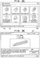
- FIGS. 5A-5F depict views for explaining an example of a screen transition of a lubrication request erasing screen displayed on the console unit 170 in a case where a user erases the lubrication request display.
- FIG. 5A illustrates an example of the main menu screen displayed on the console unit 170, and here, a case in which the CPU 201 determines that there is a need for lubricating oil to be poured onto the die-set 140 is illustrated;
- FIG. 5A corresponds to the screen of previously described FIG. 4B . Accordingly, in this screen, the request message 411 is displayed on the status display area 410, and the return process icon 412 is displayed.
- the maintenance screen illustrated in FIG. 5B is displayed.
- a "close” key 507 for causing the maintenance screen to be non-displayed is displayed.
- an "erase request display” key 508 for setting the request message 411 and the return process icon 412 to be non-displayed is displayed.
- the CPU 201 detects that a "NO" key 509 is pressed, the maintenance screen illustrated in FIG. 5B is displayed.
- the CPU 201 detects that a "YES" key 510 is pressed in the screen of FIG. 5C , it discriminates whether or not the die-set 140 is mounted by the die-set detection sensor 136 in response to that.
- the CPU 201 discriminates that the die-set 140 is not mounted, the CPU 201 displays a die-set not mounted error screen 504 illustrated in FIG. 5D . Meanwhile, in the screen of FIG.
- the lubrication request erasing confirmation screen 503 illustrated in FIG. 5C is displayed. Note that the screen of FIG. 5D is displayed because there are cases in which the die-set 140 is not mounted normally due to the lubrication to the die-set 140, and this screen is displayed when the die-set detection sensor 136 detects whether or not the die-set 140 is mounted and an abnormality is dtected.
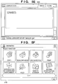
- the CPU 201 displays a lubrication request erasing completion screen 505 illustrated in FIG. 5E . Then after that, the main menu screen illustrated in FIG. 5F is displayed.
- the screen illustrated in FIG. 5F is similar to the screen of FIG. 4A , and the request message 411 and the return process icon 412 are not displayed in the status display area 410.
- FIGS. 6A through 6D depict views for illustrating an example of a screen transition of a post-lubrication initialization screen displayed on the console unit 170 in a case where a user executes an initialization after the lubrication work completes.
- the user causes a setting/registration screen as is illustrated in FIG. 6A to be displayed on the console unit 170 by operating the console unit 170.
- a setting/registration screen as is illustrated in FIG. 6A to be displayed on the console unit 170 by operating the console unit 170.
- the CPU 201 detects that a menu item 605 for initialization after lubrication of the die of the puncher unit is selected
- the CPU 201 displays a post-lubrication initialization confirmation screen 602 illustrated in FIG. 6B .
- a screen of FIG. 6B is displayed for querying the user as to whether or not lubrication work on the die of the puncher unit is complete.
- a setting/registration screen illustrated in FIG. 6A is displayed.
- the CPU 201 determines whether or not the die-set 140 is mounted by the die-set detection sensor 136. Also, if the CPU 201 determines that the die-set 140 is not mounted, the CPU 201 displays a die-set not mounted error screen 603 illustrated in FIG. 6C .
- the post-lubrication initialization confirmation screen 602 illustrated in FIG. 6B is displayed.
- the CPU 201 detects that the "YES" key 607 is pressed in the screen of FIG. 6B , and the CPU 201 discriminates that the die-set 140 mounting, the CPU 201 displays an initialization completion screen 604 as shown in FIG. 6D . Then after that, the setting/registration screen illustrated in FIG. 6A is displayed.
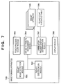
- FIG. 7 is a functional block diagram for expalining an example of a functional module configuration of the image forming apparatus 100 according to the first embodiment of the present invention.
- each functional module illustrated in FIG. 7 is a program module that is realized by a program deployed from the ROM 203 or the HDD 204 into the RAM 202 being executed by the CPU 201.
- a die-set mount detection module 701 determines whether or not the die-set 140 is mounted in accordance with a die-set mount detection signal received from the die-set detection sensor 136. Also, the die-set mount detection module 701 displays the die-set not mounted error screen 504 or 603 illustrated in FIG. 5D or FIG. 6C on the console unit 170 by a display module 708.
- a die-set identification module 702 identifies a die-set in accordance with a serial number and a die-set number read from the EEPROM 155 of the die-set 140.
- a punch process count module 703 counts the number of times that the punch process is applied by the sheet hole punching apparatus 130 using the die-set 140.
- a die-set attribute management module 704 stores the number of times that the punch process is counted by the punch process count module 703 in association with a serial number and a die-set number detected by the die-set identification module 702, in the SRAM 205 as a die-set attribute 705. Also, the die-set attribute management module 704 obtains the number of times that the punch process corresponding to the serial number detected by the die-set identification module 702 is executed from the die-set attribute 705. Also, the die-set attribute management module 704, if a user erases the lubrication request display in the procedure illustrated in FIGS.
- the die-set number is assigned to distinguish the number, size and shape of the punch hole according to the die-set. Also, in association with the die-set number, a threshold value for the number of times that the punch process is executed for prompting a user to perform work to lubricate the die-set 140 is stored in the SRAM 205 as an oiling count threshold table 706.
- a lubrication request display determination module 707 compares the number of times that the punch process corresponding to the die-set number has been executed which is obtained from the oiling count threshold table 706 and the number of times that the punch process corresponding to the serial number has been executed which is obtained from the die-set attribute 705, and determines whether or not to display a request message. Then, the lubrication request display determination module 707 displays on the console unit 170, by the display module 708, a request message for prompting a user to perform work to pour lubricating oil onto the die-set 140.
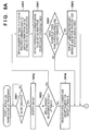
- FIGS. 8A and 8B are flowcharts for describing processing for displaying a lubrication request by the image forming apparatus 100 according to the first embodiment of the present invention.
- the CPU 201 deploying a control program stored in the ROM-for-programs in the ROM 203 or the HDD 204 into the RAM 202 and executing the control program, each step illustrated in the flowchart of FIGS. 8A and 8B is executed.
- step S801 the CPU 201, functioning as the die-set mount detection module 701, determines whether or not the die-set 140 is mounted to the punch processing unit 135.
- step S802 the CPU 201 advances the processing to step S802.
- step S802 the CPU 201, functioning as the die-set identification module 702, identifies the die-set 140 based on a die-set number and a serial number read from the EEPROM 155 of the die-set 140, and advances the processing to step S803.
- step S803 the CPU 201 determines whether or not the serial number of the die-set 140 identified in step S802 is registered in the die-set attribute 705 stored in the SRAM 205.
- step S803 the CPU 201 determines that the serial number corresponding to the die-set attribute 705 is not registered, the processing proceeds to step S804, and if the CPU 201 determines that the serial number is registered, the processing advances to step S806.
- step S804 the CPU 201, functioning as the die-set attribute management module 704, stores the die-set number and the serial number read from the EEPROM 155 of the die-set 140 in the SRAM 205 as the die-set attribute 705. Also, at this time, the number of times that the punch process corresponding to the serial number is executed is initialized and registered to the die-set attribute 705, and the processing advances to step S805 ( FIG. 8B ). With this, when a new die-set 140 is mounted, the die-set 140 is registered to the die-set attribute 705.
- step S806 the CPU 201, functioning as the die-set attribute management module 704, obtains from the die-set attribute 705 the number of times that the punch process corresponding to the serial number read from the EEPROM 155 of the die-set 140 has been executed, and the processing advances to step S807.
- step S807 the CPU 201, functioning as the lubrication request display determination module 707, obtains from the oiling count threshold table 706 the threshold value for the number of times that the punch process corresponding to the die-set number read from the EEPROM 155 of the die-set 140 has been executed, and the processing advances to step S808.
- the CPU 201 determines whether or not the number of times that the punch process corresponding to the serial number has been executed which is obtained from the die-set attribute 705 exceeds the threshold value of the number of times that the punch process corresponding to the die-set number has been executed which is obtained from the oiling count threshold table 706. If it is determined that the threshold value is exceeded, the processing proceeds to step S809, and if it is determined that the threshold value is not exceeded, the processing advances to step S805.
- the CPU 201 functions as the display module 708, and as is illustrated in FIG. 4B , the request message 411 and the return process icon 412 are displayed on the status display area 410 of the menu screen, and the processing advances to step S805.
- the request message can be displayed to the user so that the die-set 140 is lubricated.
- step S805 the CPU 201 determines whether or not a print job is inputted, and if the CPU 201 determines that the print job is inputted, the processing advances to step S810.
- step S810 the CPU 201 determines whether or not the punch process is designated for the inputted print job, and when it is determined that the punch process is not designated in the job, the processing proceeds to step S811, the CPU 201 executes normal print processing, and this processing terminates.
- step S810 if the CPU 201 determines that the print job designates the punch process, the processing advances to step S812.
- step S812 the CPU 201 executes the punch process by the sheet hole punching apparatus 130 using the die-set 140, and the processing advances to step S813.
- the punch process count module 703 counts the number of times the punch process has been executed in step S812.
- step S813 the CPU 201 adds the number of times that the punch process corresponding to the serial number of the die-set 140 has been executed which is obtained from the die-set attribute 705 and the number of times that the punch process has been executed which is counted by the punch process count module 703.
- step S814 the CPU 201, functioning as the die-set attribute management module 704, stores the added up number of times that the punch process has been executed in the SRAM as the die-set attribute 705, and the processing advances to step S814.
- the CPU 201 similarly to in step S807, obtains the threshold value for the number of times that the punch process corresponding to the die-set number of the die-set 140 has been executed from the oiling count threshold table 706 of the SRAM 205 by the lubrication request display determination module 707, and the processing advances to step S815.
- step S815 the CPU 201, similarly to in step S808, determines whether or not the number of times that the punch process has been executed for that die-set 140 exceeds the threshold value for the number of times that the punch process has been executed which is obtained from the oiling count threshold table 706.
- the processing proceeds to step S816, and as is illustrated in FIG. 4B , for example, the request message 411 and the return process icon 412 are displayed on the status display area 410, and this processing terminates. Meanwhile, if the CPU 201, in step S815, determines that the threshold value is not exceeded, the processing terminates as is.
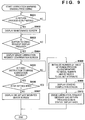
- FIG. 9 is a flowchart for describing processing for erasing a lubrication request by the image forming apparatus 100 according to the first embodiment of the present invention.
- the CPU 201 deploying a control program stored in the ROM-for-programs in the ROM 203 or the HDD 204 into the RAM 202 and executing the control program, each step illustrated in the flowchart of FIG. 9 is executed.
- step S901 the CPU 201 determine whether or not the return process icon 412 is pressed by a user in a state in which the screen illustrated in FIG. 4B or FIG. 5A is displayed. If the CPU 201 determines that the return process icon 412 is pressed, the processing advances to step S902 from step S901. In step S902, the CPU 201 displays on the console unit 170 a maintenance screen as is illustrated in FIG. 5B , for example, and the processing advances to step S903. In step S903, the CPU 201 determines whether or not the user pressed the "erase request display" key 508 in the screen of FIG. 5B .
- step S904 the processing advances to step S904 from step S903.
- step S904 the CPU 201 displays on the console unit 170 the lubrication request erasing confirmation screen 503 as is illustrated in FIG. 5C , for example, and the processing advances to step S905.
- step S905 the CPU 201 determines whether or not it is instructed that the lubrication request display be erased by the "YES" key 510 being pressed on the screen of FIG. 5C . If it is determined that the "YES" key 510 is pressed, the processing advances to step S906 from step S905.
- step S906 the CPU 201, functioning as the die-set mount detection module 701, determines whether or not the die-set 140 is mounted to the punch processing unit 135. If the CPU 201, in step S906, determines that the die-set 140 is not mounted, the processing proceeds to step S907, and the CPU 201, for example, displays the die-set not mounted error screen 504 illustrated in FIG. 5D on the console unit 170, and this processing terminates.
- step S906 determines that the die-set 140 is mounted, the processing advances to step S908.
- step S908 the CPU 201, functioning as the die-set attribute management module 704, initializes the number of times that the punch process corresponding to the serial number read from the EEPROM 155 of the die-set 140 has been executed. Then, the CPU 201, functioning as the die-set attribute management module 704, registers the initialized number of times that the punch process has been executed to the die-set attribute 705, and the processing advances to step S909.
- step S909 the CPU 201 displays on the console unit 170 the lubrication request erasing completion screen 505 as illustrated in FIG. 5E , for example, and the processing advances to step S910.
- step S910 the CPU 201 sets the request message 411 and the return process icon 412 that are displayed in the status display area 410 as shown in FIG. 5F , for example, to be non-displayed, and this processing terminates.
- a user can clear the request message 411 and the return process icon 412 displayed on the screen of FIG. 4B or FIG. 5A after lubricating the die-set 140 of the punch processing unit 135. Also, in addition to erasing the message and icon (button), the number of times that the punch process has been executed by that die-set can be initialized.
- FIG. 10 is a flowchart for describing post-lubrication initialization processing by the image forming apparatus 100 according to a first embodiment of the present invention.
- the CPU 201 deploying a control program stored in the ROM-for-programs in the ROM 203 or the HDD 204 into the RAM 202 and executing the control program, each step illustrated in the flowchart of FIG. 10 is executed.
- step S1001 displays the screen of FIG. 6A , for example, and determines whether or not the menu item 605 for initialization after lubrication of the die of the puncher unit is selected on the screen. If it is determined that the menu item 605 for initialization after lubrication of the die of the puncher unit is selected, the processing advances to step S1002 from step S1001. In step S1002, the CPU 201 displays on the console unit 170 the post-lubrication initialization confirmation screen 602 as shown in FIG. 6B , for example, and the processing advances to step S1003.
- step S1003 the CPU 201 determines whether or not the post-lubrication initialization is instructed by the "YES" key 607 being pressed on the screen illustrated in FIG. 6B , for example. If the CPU 201 determines that post-lubrication initialization is instructed, the processing advances to step S1004 from step S1003.
- step S1004 the CPU 201, functioning as the die-set mount detection module 701, determines whether or not the die-set 140 is mounted to the punch processing unit 135.
- the processing proceeds to step S1005, the CPU 201 displays the die-set not mounted error screen 603 as shown in FIG. 6C , for example, on the console unit 170, and this processing terminates.
- step S1004 determines that the die-set 140 is mounted, the processing advances to step S1006.
- step S1006 the CPU 201, functioning as the die-set attribute management module 704, initializes the number of times that the punch process corresponding to the serial number read from the EEPROM 155 of the die-set 140 has been executed. Then, the CPU 201, functioning as the die-set attribute management module 704, registers the initialized number of times that the punch process has been executed to the die-set attribute 705, and the processing advances to step S1007.
- step S1007 the CPU 201 displays on the console unit 170 the initialization completion screen 604 as shown in FIG. 6D , for example, and the processing terminates.
- Embodiments of the present invention can also be realized by a computer of a system or apparatus that reads out and executes computer executable instructions (e.g., one or more programs) recorded on a storage medium (which may also be referred to more fully as a 'non-transitory computer-readable storage medium') to perform the functions of one or more of the above-described embodiment(s) and/or that includes one or more circuits (e.g., application specific integrated circuit (ASIC)) for performing the functions of one or more of the above-described embodiment(s), and by a method performed by the computer of the system or apparatus by, for example, reading out and executing the computer executable instructions from the storage medium to perform the functions of one or more of the above-described embodiments and/or controlling the one or more circuits to perform the functions of one or more of the above-described embodiments.
- computer executable instructions e.g., one or more programs
- a storage medium which may also be referred to more fully as a 'non-
- the computer may comprise one or more processors (e.g., central processing unit (CPU), micro processing unit (MPU)) and may include a network of separate computers or separate processors to read out and execute the computer executable instructions.
- the computer executable instructions may be provided to the computer, for example, from a network or the storage medium.
- the storage medium may include, for example, one or more of a hard disk, a random-access memory (RAM), a read only memory (ROM), a storage of distributed computing systems, an optical disk (such as a compact disc (CD), digital versatile disc (DVD), or Blu-ray Disc (BD)TM), a flash memory device, a memory card, and the like.
Landscapes
- Engineering & Computer Science (AREA)
- Multimedia (AREA)
- Signal Processing (AREA)
- Biomedical Technology (AREA)
- General Health & Medical Sciences (AREA)
- Health & Medical Sciences (AREA)
- General Physics & Mathematics (AREA)
- Physics & Mathematics (AREA)
- Mechanical Engineering (AREA)
- Life Sciences & Earth Sciences (AREA)
- Forests & Forestry (AREA)
- Human Computer Interaction (AREA)
- Microelectronics & Electronic Packaging (AREA)
- General Engineering & Computer Science (AREA)
- Automation & Control Theory (AREA)
- Folding Of Thin Sheet-Like Materials, Special Discharging Devices, And Others (AREA)
- Accessory Devices And Overall Control Thereof (AREA)
- Control Or Security For Electrophotography (AREA)
- Paper Feeding For Electrophotography (AREA)
- Facsimiles In General (AREA)
Abstract
Description
- The present invention relates to an image forming apparatus, a method of controlling the same, and a storage medium.
- Conventionally, in a field of production printing using an image forming apparatus such as a laser printer or a digital multifunction peripheral, a sheet hole punching apparatus that applies various punch processes to printed sheets by replacing a part referred to as a die-set in which a punch blade and a die are integrated into a single body is known. There exists a usage limit for a die-set mounted in such a sheet hole punching apparatus, and when the die-set reaches the usage limit, scruffing of the periphery of the die or the punch blade occurs, and punch waste ceases to separate from the sheet, and there are cases in which these cause a jam of a printed sheet. In order to resolve this problem, Japanese Patent Laid-Open No.
2011-54099 - However, it is necessary that periodic maintenance work be performed by a user in order for the usage limit of a die-set to be reached, that is for the original die-set life span to be fulfilled, and lubrication work such as pouring a lubricating oil onto the die-set every predetermined number of times that the hole punching is performed is particularly essential. Furthermore, because the time period in which a die-set will degrade differs depending on the number, size, and shape of punch holes, or the like, it is necessary that the lubrication work be performed considering the work time periods that differ for each die-set.
- An aspect of the present invention is to eliminate the above-mentioned problems which are found in the conventional technology.
- A feature of the present invention is to provide a technique by which it is possible to prompt a user to perform work to lubricate a die-set at the optimal timing for each die-set.
- The present invention in its first aspect provides an image forming apparatus as specified in
claims 1 to 12. - The present invention in its second aspect provides a method of controlling an image forming apparatus as specified in claims 13 and 14.
- The present invention in its third aspect provides a computer-readable storage medium as specified in claim 15.
- Further features of the present invention will become apparent from the following description of exemplary embodiments with reference to the attached drawings. Note, in the accompanying drawings, the same reference numerals are added for same or similar configuration elements.
- The accompanying drawings, which are incorporated in and constitute a part of the specification, illustrate embodiments of the invention and, together with the description, serve to explain the principles of the invention.
-
FIG. 1 is a block diagram for explaining a configuration of an image forming apparatus according to a first embodiment of the present invention. -
FIG. 2 is a block diagram for explaining a configuration of a control unit of the image forming apparatus according to the first embodiment. -
FIG. 3 is a diagram for explaining an example of a die-set that is mountable to a sheet hole punching apparatus according to the first embodiment. -
FIGS. 4A and 4B depict views for explaining an example of screen transition of a lubrication request display screen displayed in a console unit in a case where a user is prompted to perform lubrication work in the image forming apparatus according to the first embodiment. -
FIGS. 5A-5F depict views for explaining an example of screen transition of a lubrication request erasing screen displayed in the console unit in a case where a user erases the lubrication request display in the image forming apparatus according to the first embodiment. -
FIGS. 6A-6D depict views for explaining an example of screen transition of a post-lubrication initialization screen displayed in the console unit in a case where a user executes an initialization after lubrication work is completed in the image forming apparatus according to the first embodiment. -
FIG. 7 is a functional block diagram for explaining an example of a functional module configuration of the image forming apparatus according to the first embodiment. -
FIGS. 8A and8B are flowcharts for describing processing for displaying a lubrication request by the image forming apparatus according to the first embodiment. -
FIG. 9 is a flowchart for describing processing for erasing a lubrication request by the image forming apparatus according to the first embodiment. -
FIG. 10 is a flowchart for describing post-lubrication initialization processing by the image forming apparatus according to the first embodiment. - Embodiments of the present invention will be described hereinafter in detail, with reference to the accompanying drawings. It is to be understood that the following embodiments are not intended to limit the claims of the present invention, and that not all of the combinations of the aspects that are described according to the following embodiments are necessarily required with respect to the means to solve the problems according to the present invention.
-
FIG. 1 is a block diagram for explaining a configuration of animage forming apparatus 100 according to a first embodiment of the present invention. - The
image forming apparatus 100 comprises areader unit 110, aprinter unit 120, acontrol unit 160, and aconsole unit 170. Also, theimage forming apparatus 100 is connected electronically with a sheethole punching apparatus 130. Note that theimage forming apparatus 100 is not limited to a form in which it is connected with the sheethole punching apparatus 130, and theimage forming apparatus 100 may include the sheethole punching apparatus 130. - The
reader unit 110 comprises anoriginal conveyance unit 111 for conveying an original, and ascanner unit 112 for reading an image on the original that is conveyed by theoriginal conveyance unit 111. Image data read by thescanner unit 112 is input into thecontrol unit 160. - The
printer unit 120 comprises afeed unit 121 and amarking unit 122. Thefeed unit 121 includes a plurality of feed cassettes that respectively store recording sheets of differing sizes, and a manual feed tray on which special sheets such as an envelope or OHP or coated paper can be placed, and thefeed unit 121 feeds recording sheets (sheets) from each feed cassette and the manual feed tray. Themarking unit 122 is a unit that executes, for example, an image forming process by an electrophotographic method. Upon a copy operation, themarking unit 122 forms (prints) an image on a sheet that is fed from thefeed unit 121 based on image data input via thecontrol unit 160 from thescanner unit 112. - The
control unit 160 is electronically connected to thereader unit 110 and theprinter unit 120. Thecontrol unit 160 realizes a copy function by inputting image data generated by thereader unit 110 reading an original, and outputting the image data to theprinter unit 120 to control so as to print an image on a sheet. - The
console unit 170 comprises a display unit for displaying various keys for performing an input of an instruction to thecontrol unit 160 and user interface screens, and theconsole unit 170 outputs to thecontrol unit 160 by generating corresponding signals in accordance with various key operations. - The sheet
hole punching apparatus 130 comprises apunch processing unit 135 and a die-set 140. Thepunch processing unit 135 applies a punch process to a sheet that is printed by themarking unit 122 and discharges to the outside of the apparatus. Also, thepunch processing unit 135 is able to execute punch processes of differing numbers of punch holes, punch hole sizes and punch hole shapes by replacing the die-set 140. - Next, explanation is given for a detailed configuration of the
control unit 160 with reference toFIG. 2 . -
FIG. 2 is a block diagram for explaining a configuration of thecontrol unit 160 of theimage forming apparatus 100 according to the first embodiment. Note that inFIG. 2 , portions common toFIG. 1 are illustrated with the same reference numerals. - In the
control unit 160, aCPU 201 controls theimage forming apparatus 100 and the sheethole punching apparatus 130. ARAM 202 is a system work memory for theCPU 201 to operate, and is an image memory for temporarily storing image data. AROM 203 comprises a boot ROM, and stores a boot program. Also, a ROM-for-data of theROM 203 is a non-volatile memory that can write and erase electronically stored content, and is, for example, an EEPROM, and can store various data that is explained later, or the like. A hard disk drive (HDD) 204 stores an OS, and software for control, and image data. A console unit I/F 206 is a unit that interfaces theconsole unit 170, and the console unit I/F 206 outputs to theconsole unit 170 the image data that should be displayed on theconsole unit 170, and transmits to theCPU 201 information that a user inputs via theconsole unit 170. An SRAM 205 is backed up by a battery, and is used by theCPU 201 for storing information desired to be held when a power supply of the apparatus is turned off. Animage bus interface 208 is a bus bridge for controlling an interface between asystem bus 207 and animage bus 209. These devices are arranged on thesystem bus 207. - A device I/F 210, a
scanner image processor 211, aprinter image processor 212, animage rotation unit 213, and animage codex unit 214 are arranged on theimage bus 209. - The device I/F 210 is connected to the
reader unit 110 and theprinter unit 120, and converts image data for synchronous or non-synchronous systems. Thescanner image processor 211 performs image processing such as noise reduction, shifting, masking/trimming, enlargement/reduction, tone conversion or the like in accordance with an instruction from theCPU 201 with respect to image data input from thereader unit 110. Theprinter image processor 212 performs image processing such as correction, resolution conversion, or the like, with respect to image data to be output to theprinter unit 120. Theimage rotation unit 213 performs rotation processing with respect to image data. Theimage codex unit 214 performs JPEG compression/decompression processing for multi-valued image data, and performs compression/decompression processing such as that of JBIG, MMR, MR, MH or the like for binary image data. - Note that the
CPU 201 comprehensively controls access between various devices connected to thesystem bus 207 based on control programs stored in a ROM-for-programs in theROM 203 or theHDD 204. Also, theCPU 201 inputs image data from thereader unit 110 connected via areader unit interface 215, and outputs an image signal as output information to theprinter unit 120 connected via aprinter unit interface 216. Display control procedures illustrated in later describedFIG. 8A through FIG. 10 are realized by control programs stored in the ROM-for-programs of theROM 203 or theHDD 204 being deployed into theRAM 202 and theCPU 201 processing based on the control programs. - In the
punch processing unit 135, a die-setdetection sensor 136 and the die-set 140 are comprised. The die-setdetection sensor 136 is a sensor for detecting whether or not the die-set 140 is mounted. For example, the die-setdetection sensor 136 is a transmissive optical sensor and when the die-set 140 is mounted, the optical sensor is disconnected by a protruding portion formed on a base of the die-set (not shown). Thereby, the die-setdetection sensor 136 detects that the die-set 140 is mounted at a predetermined position, and notifies theCPU 201. - Next, explanation is given of a detailed configuration of the die-set 140 with reference to
FIG. 3 . -
FIG. 3 depicts a view for explaining an example of the die-set 140 that is mountable to the sheethole punching apparatus 130 according to the first embodiment. - The die-set 140 is configured by a plurality of parts. As an example, a 3 hole die-set having 3 punch blades is explained in
FIG. 3 . Adie 141 comprises punch holes that accommodate the leading edge portions of punch blades 142-144. Aguide board 145 comprises holes respectively through which the punch blades 142-144 pass. Thedie 141 and theguide board 145 are connected byguide pins member 148 supports theguide board 145. Each of the punch blades 142-144 is fixed to a holdingboard 152 by the corresponding punch holders 149-151. By a printed sheet being conveyed between theguide board 145 and thedie 141, and the holdingboard 152 being pressed down, holes are opened in the sheet by the blade tips of the punch blades 142-144 fixed on the holdingboard 152. There arecoil springs board 152 and theguide board 145, and when the force pressing down the holdingboard 152 is released, the coil springs 153 and 154 return the holdingboard 152 to its original position. - Here by pouring an appropriate amount of lubricating oil on the leading edge portion of the punch blades 142-144, the degradation of the die-set can be prevented. Also, because the coil springs 153 and 154 that move vertically are also parts on which a large load is applied, degradation of the die-set can be prevented by pouring an appropriate amount of lubricating oil thereon.
- An
EEPROM 155 is installed in the die-set 140, and die-set information including a serial number of the die-set 140 and a die-set number are stored. Here, the serial number is identification information comprised by a 7-character string for identifying the die-set uniquely. Meanwhile, the die-set number is a number allocated to a die-set in order to distinguish the number of punch holes, the size of punch holes, and the shape of punch holes. When the die-set 140 is mounted to thepunch processing unit 135, theCPU 201 is able to access to theEEPROM 155. - When the die-set 140 is mounted to the
punch processing unit 135, mounting of the die-set 140 is detected by the die-setdetection sensor 136, and theCPU 201 obtains the serial number and the die-set number stored in theEEPROM 155 of the die-set 140. - Next, with reference to
FIGS. 4A and 4B , explanation is given for a procedure for displaying a request message for prompting a user to perform work of pouring lubricating oil on the die-set 140. -
FIGS. 4A and 4B depict views for explaining an example of a screen transition of a lubrication request display that is displayed on theconsole unit 170 in a case where a user is prompted to perform lubrication work. Here,FIG. 4A depicts a view for illustrating a main menu screen prior to a lubrication request being generated, andFIG. 4B depicts a view for illustrating a main menu screen after the lubrication request is generated. - When a power supply of the
image forming apparatus 100 is turned on, and theimage forming apparatus 100 activates, theCPU 201 displays the main menu screen which is an initial screen illustrated inFIG. 4A , for example, on theconsole unit 170. Note that a bottommost line of the screen is reserved as astatus display area 410 when not only the main menu screen but also other screens are displayed. - The
CPU 201 displays a message to thestatus display area 410 when a situation that a user should know about occurs. If theCPU 201 determines that it is necessary that lubricating oil be poured onto the die-set 140, as is illustrated inFIG. 4B , theCPU 201 displays arequest message 411 in thestatus display area 410, and displays areturn process icon 412. Here, therequest message 411 prompts the user to lubricate the die of the puncher unit. Also, thereturn process icon 412 is used to instruct to return to an original normal state after erasing the lubrication request display. - Next, with reference to
FIGS. 5A through 5F , explanation is given for a procedure for erasing therequest message 411 for prompting a user to perform work of pouring lubricating oil on the die-set 140. -
FIGS. 5A-5F depict views for explaining an example of a screen transition of a lubrication request erasing screen displayed on theconsole unit 170 in a case where a user erases the lubrication request display. -
FIG. 5A illustrates an example of the main menu screen displayed on theconsole unit 170, and here, a case in which theCPU 201 determines that there is a need for lubricating oil to be poured onto the die-set 140 is illustrated;FIG. 5A corresponds to the screen of previously describedFIG. 4B . Accordingly, in this screen, therequest message 411 is displayed on thestatus display area 410, and thereturn process icon 412 is displayed. - In the screen of
FIG. 5A , when theCPU 201 detects that thereturn process icon 412 is pressed, the maintenance screen illustrated inFIG. 5B is displayed. In the screen ofFIG. 5B , a "close"key 507 for causing the maintenance screen to be non-displayed is displayed. Also, in the screen ofFIG. 5B , an "erase request display"key 508 for setting therequest message 411 and thereturn process icon 412 to be non-displayed is displayed. - In the screen of
FIG. 5B , when theCPU 201 detects that the "close" key 507 is pressed, the main menu screen illustrated inFIG. 5A is displayed. Meanwhile, in the screen ofFIG. 5B , when theCPU 201 detects that the "erase request display"key 508 is pressed, an erasing of requesting display confirmation screen 503 illustrated inFIG. 5C is displayed. - In the screen of
FIG. 5C , when theCPU 201 detects that a "NO" key 509 is pressed, the maintenance screen illustrated inFIG. 5B is displayed. On the other hand, when theCPU 201 detects that a "YES"key 510 is pressed in the screen ofFIG. 5C , it discriminates whether or not the die-set 140 is mounted by the die-setdetection sensor 136 in response to that. Also, when theCPU 201 discriminates that the die-set 140 is not mounted, theCPU 201 displays a die-set not mounted error screen 504 illustrated inFIG. 5D . Meanwhile, in the screen ofFIG. 5D , when theCPU 201 detects that an "OK" key 511 is pressed, the lubrication request erasing confirmation screen 503 illustrated inFIG. 5C is displayed. Note that the screen ofFIG. 5D is displayed because there are cases in which the die-set 140 is not mounted normally due to the lubrication to the die-set 140, and this screen is displayed when the die-setdetection sensor 136 detects whether or not the die-set 140 is mounted and an abnormality is dtected. - Meanwhile, when the "erase request display"
key 508 is pressed in the screen ofFIG. 5B , and theCPU 201 discriminates that the die-set 140 is mounted, theCPU 201 displays a lubrication request erasing completion screen 505 illustrated inFIG. 5E . Then after that, the main menu screen illustrated inFIG. 5F is displayed. The screen illustrated inFIG. 5F is similar to the screen ofFIG. 4A , and therequest message 411 and thereturn process icon 412 are not displayed in thestatus display area 410. - Next, with reference to
FIGS. 6A-6D , explanation is given for a procedure in which a lubrication work is completed prior to the request message being displayed to prompt a user to perform work of pouring lubricating oil on the die-set 140. -
FIGS. 6A through 6D depict views for illustrating an example of a screen transition of a post-lubrication initialization screen displayed on theconsole unit 170 in a case where a user executes an initialization after the lubrication work completes. - The user causes a setting/registration screen as is illustrated in
FIG. 6A to be displayed on theconsole unit 170 by operating theconsole unit 170. In the screen ofFIG. 6A , when theCPU 201 detects that amenu item 605 for initialization after lubrication of the die of the puncher unit is selected, theCPU 201 displays a post-lubricationinitialization confirmation screen 602 illustrated inFIG. 6B . A screen ofFIG. 6B is displayed for querying the user as to whether or not lubrication work on the die of the puncher unit is complete. - In the screen of
FIG. 6B , when theCPU 201 detects that a "NO" key 606 is pressed, a setting/registration screen illustrated inFIG. 6A is displayed. On the other hand, when theCPU 201 detects that a "YES"key 607 is pressed in the screen ofFIG. 6B , theCPU 201 determines whether or not the die-set 140 is mounted by the die-setdetection sensor 136. Also, if theCPU 201 determines that the die-set 140 is not mounted, theCPU 201 displays a die-set not mountederror screen 603 illustrated inFIG. 6C . In the screen ofFIG. 6C , when theCPU 201 detects that an "OK" key 608 is pressed, the post-lubricationinitialization confirmation screen 602 illustrated inFIG. 6B is displayed. - Meanwhile, when the
CPU 201 detects that the "YES"key 607 is pressed in the screen ofFIG. 6B , and theCPU 201 discriminates that the die-set 140 mounting, theCPU 201 displays aninitialization completion screen 604 as shown inFIG. 6D . Then after that, the setting/registration screen illustrated inFIG. 6A is displayed. -
FIG. 7 is a functional block diagram for expalining an example of a functional module configuration of theimage forming apparatus 100 according to the first embodiment of the present invention. Note that each functional module illustrated inFIG. 7 is a program module that is realized by a program deployed from theROM 203 or theHDD 204 into theRAM 202 being executed by theCPU 201. - A die-set
mount detection module 701 determines whether or not the die-set 140 is mounted in accordance with a die-set mount detection signal received from the die-setdetection sensor 136. Also, the die-setmount detection module 701 displays the die-set not mountederror screen 504 or 603 illustrated inFIG. 5D orFIG. 6C on theconsole unit 170 by adisplay module 708. - A die-set
identification module 702 identifies a die-set in accordance with a serial number and a die-set number read from theEEPROM 155 of the die-set 140. - A punch
process count module 703 counts the number of times that the punch process is applied by the sheethole punching apparatus 130 using the die-set 140. - A die-set
attribute management module 704 stores the number of times that the punch process is counted by the punchprocess count module 703 in association with a serial number and a die-set number detected by the die-setidentification module 702, in theSRAM 205 as a die-setattribute 705. Also, the die-setattribute management module 704 obtains the number of times that the punch process corresponding to the serial number detected by the die-setidentification module 702 is executed from the die-setattribute 705. Also, the die-setattribute management module 704, if a user erases the lubrication request display in the procedure illustrated inFIGS. 5A-5E , initializes the number of times that the punch process corresponding to the serial number detected by the die-setidentification module 702 has been executed, which is stored in theSRAM 205 as the die-setattribute 705. Also, if a user executes an initialization after completing the lubrication work in the procedure illustrated inFIGS. 6A-6D , the number of times that the punch process corresponding to the serial number detected by the die-setidentification module 702 has been executed, which is stored in theSRAM 205 as the die-setattribute 705, is initialized. - Here, the die-set number is assigned to distinguish the number, size and shape of the punch hole according to the die-set. Also, in association with the die-set number, a threshold value for the number of times that the punch process is executed for prompting a user to perform work to lubricate the die-set 140 is stored in the
SRAM 205 as an oiling count threshold table 706. - A lubrication request
display determination module 707 compares the number of times that the punch process corresponding to the die-set number has been executed which is obtained from the oiling count threshold table 706 and the number of times that the punch process corresponding to the serial number has been executed which is obtained from the die-setattribute 705, and determines whether or not to display a request message. Then, the lubrication requestdisplay determination module 707 displays on theconsole unit 170, by thedisplay module 708, a request message for prompting a user to perform work to pour lubricating oil onto the die-set 140. -
FIGS. 8A and8B are flowcharts for describing processing for displaying a lubrication request by theimage forming apparatus 100 according to the first embodiment of the present invention. By theCPU 201 deploying a control program stored in the ROM-for-programs in theROM 203 or theHDD 204 into theRAM 202 and executing the control program, each step illustrated in the flowchart ofFIGS. 8A and8B is executed. - Firstly, in step S801, the
CPU 201, functioning as the die-setmount detection module 701, determines whether or not the die-set 140 is mounted to thepunch processing unit 135. When it is determined, in step S801, that the die-set 140 is mounted, theCPU 201 advances the processing to step S802. In step S802, theCPU 201, functioning as the die-setidentification module 702, identifies the die-set 140 based on a die-set number and a serial number read from theEEPROM 155 of the die-set 140, and advances the processing to step S803. In step S803, theCPU 201 determines whether or not the serial number of the die-set 140 identified in step S802 is registered in the die-setattribute 705 stored in theSRAM 205. If, in step S803, theCPU 201 determines that the serial number corresponding to the die-setattribute 705 is not registered, the processing proceeds to step S804, and if theCPU 201 determines that the serial number is registered, the processing advances to step S806. In step S804, theCPU 201, functioning as the die-setattribute management module 704, stores the die-set number and the serial number read from theEEPROM 155 of the die-set 140 in theSRAM 205 as the die-setattribute 705. Also, at this time, the number of times that the punch process corresponding to the serial number is executed is initialized and registered to the die-setattribute 705, and the processing advances to step S805 (FIG. 8B ). With this, when a new die-set 140 is mounted, the die-set 140 is registered to the die-setattribute 705. - Meanwhile, in step S806, the
CPU 201, functioning as the die-setattribute management module 704, obtains from the die-setattribute 705 the number of times that the punch process corresponding to the serial number read from theEEPROM 155 of the die-set 140 has been executed, and the processing advances to step S807. In step S807, theCPU 201, functioning as the lubrication requestdisplay determination module 707, obtains from the oiling count threshold table 706 the threshold value for the number of times that the punch process corresponding to the die-set number read from theEEPROM 155 of the die-set 140 has been executed, and the processing advances to step S808. TheCPU 201, in step S808, determines whether or not the number of times that the punch process corresponding to the serial number has been executed which is obtained from the die-setattribute 705 exceeds the threshold value of the number of times that the punch process corresponding to the die-set number has been executed which is obtained from the oiling count threshold table 706. If it is determined that the threshold value is exceeded, the processing proceeds to step S809, and if it is determined that the threshold value is not exceeded, the processing advances to step S805. In step S809, theCPU 201 functions as thedisplay module 708, and as is illustrated inFIG. 4B , therequest message 411 and thereturn process icon 412 are displayed on thestatus display area 410 of the menu screen, and the processing advances to step S805. - By this processing, when it is determined that the number of times that the punch process has been executed by the die-set 140 exceeds the threshold value of the oiling count threshold table 706, the request message can be displayed to the user so that the die-set 140 is lubricated.
- The processing proceeds to step S805, and the
CPU 201 determines whether or not a print job is inputted, and if theCPU 201 determines that the print job is inputted, the processing advances to step S810. In step S810, theCPU 201 determines whether or not the punch process is designated for the inputted print job, and when it is determined that the punch process is not designated in the job, the processing proceeds to step S811, theCPU 201 executes normal print processing, and this processing terminates. - Meanwhile, in step S810, if the
CPU 201 determines that the print job designates the punch process, the processing advances to step S812. In step S812, theCPU 201 executes the punch process by the sheethole punching apparatus 130 using the die-set 140, and the processing advances to step S813. At this point, the punchprocess count module 703 counts the number of times the punch process has been executed in step S812. In step S813, theCPU 201 adds the number of times that the punch process corresponding to the serial number of the die-set 140 has been executed which is obtained from the die-setattribute 705 and the number of times that the punch process has been executed which is counted by the punchprocess count module 703. Then, theCPU 201, functioning as the die-setattribute management module 704, stores the added up number of times that the punch process has been executed in the SRAM as the die-setattribute 705, and the processing advances to step S814. In step S814, theCPU 201, similarly to in step S807, obtains the threshold value for the number of times that the punch process corresponding to the die-set number of the die-set 140 has been executed from the oiling count threshold table 706 of theSRAM 205 by the lubrication requestdisplay determination module 707, and the processing advances to step S815. In step S815, theCPU 201, similarly to in step S808, determines whether or not the number of times that the punch process has been executed for that die-set 140 exceeds the threshold value for the number of times that the punch process has been executed which is obtained from the oiling count threshold table 706. Here, if theCPU 201 determines that the threshold value is exceeded, the processing proceeds to step S816, and as is illustrated inFIG. 4B , for example, therequest message 411 and thereturn process icon 412 are displayed on thestatus display area 410, and this processing terminates. Meanwhile, if theCPU 201, in step S815, determines that the threshold value is not exceeded, the processing terminates as is. - By this processing, if the number of times that the punch process has been executed by the die-set 140, due to the punch process being executed, exceeds the threshold value of the oiling count threshold table 706, it is possible to display a request message to a user so that the die-set 140 is lubricated.
-
FIG. 9 is a flowchart for describing processing for erasing a lubrication request by theimage forming apparatus 100 according to the first embodiment of the present invention. By theCPU 201 deploying a control program stored in the ROM-for-programs in theROM 203 or theHDD 204 into theRAM 202 and executing the control program, each step illustrated in the flowchart ofFIG. 9 is executed. - Firstly, in step S901, the
CPU 201 determine whether or not thereturn process icon 412 is pressed by a user in a state in which the screen illustrated inFIG. 4B orFIG. 5A is displayed. If theCPU 201 determines that thereturn process icon 412 is pressed, the processing advances to step S902 from step S901.
In step S902, theCPU 201 displays on the console unit 170 a maintenance screen as is illustrated inFIG. 5B , for example, and the processing advances to step S903. In step S903, theCPU 201 determines whether or not the user pressed the "erase request display" key 508 in the screen ofFIG. 5B . Here, if it is determined that the "erase request display"key 508 is pressed, the processing advances to step S904 from step S903. In step S904, theCPU 201 displays on theconsole unit 170 the lubrication request erasing confirmation screen 503 as is illustrated inFIG. 5C , for example, and the processing advances to step S905. In step S905, theCPU 201 determines whether or not it is instructed that the lubrication request display be erased by the "YES" key 510 being pressed on the screen ofFIG. 5C . If it is determined that the "YES"key 510 is pressed, the processing advances to step S906 from step S905. In step S906, theCPU 201, functioning as the die-setmount detection module 701, determines whether or not the die-set 140 is mounted to thepunch processing unit 135. If theCPU 201, in step S906, determines that the die-set 140 is not mounted, the processing proceeds to step S907, and theCPU 201, for example, displays the die-set not mounted error screen 504 illustrated inFIG. 5D on theconsole unit 170, and this processing terminates. - Meanwhile, if the
CPU 201, in step S906, determines that the die-set 140 is mounted, the processing advances to step S908. In step S908, theCPU 201, functioning as the die-setattribute management module 704, initializes the number of times that the punch process corresponding to the serial number read from theEEPROM 155 of the die-set 140 has been executed. Then, theCPU 201, functioning as the die-setattribute management module 704, registers the initialized number of times that the punch process has been executed to the die-setattribute 705, and the processing advances to step S909. In step S909, theCPU 201 displays on theconsole unit 170 the lubrication request erasing completion screen 505 as illustrated inFIG. 5E , for example, and the processing advances to step S910. In step S910, theCPU 201 sets therequest message 411 and thereturn process icon 412 that are displayed in thestatus display area 410 as shown inFIG. 5F , for example, to be non-displayed, and this processing terminates. - By this processing, a user can clear the
request message 411 and thereturn process icon 412 displayed on the screen ofFIG. 4B orFIG. 5A after lubricating the die-set 140 of thepunch processing unit 135. Also, in addition to erasing the message and icon (button), the number of times that the punch process has been executed by that die-set can be initialized. -
FIG. 10 is a flowchart for describing post-lubrication initialization processing by theimage forming apparatus 100 according to a first embodiment of the present invention. By theCPU 201 deploying a control program stored in the ROM-for-programs in theROM 203 or theHDD 204 into theRAM 202 and executing the control program, each step illustrated in the flowchart ofFIG. 10 is executed. - Firstly, the
CPU 201, in step S1001, displays the screen ofFIG. 6A , for example, and determines whether or not themenu item 605 for initialization after lubrication of the die of the puncher unit is selected on the screen. If it is determined that themenu item 605 for initialization after lubrication of the die of the puncher unit is selected, the processing advances to step S1002 from step S1001. In step S1002, theCPU 201 displays on theconsole unit 170 the post-lubricationinitialization confirmation screen 602 as shown inFIG. 6B , for example, and the processing advances to step S1003. In step S1003, theCPU 201 determines whether or not the post-lubrication initialization is instructed by the "YES" key 607 being pressed on the screen illustrated inFIG. 6B , for example. If theCPU 201 determines that post-lubrication initialization is instructed, the processing advances to step S1004 from step S1003. In step S1004, theCPU 201, functioning as the die-setmount detection module 701, determines whether or not the die-set 140 is mounted to thepunch processing unit 135. Here, if it is determined that the die-set 140 is not mounted, the processing proceeds to step S1005, theCPU 201 displays the die-set not mountederror screen 603 as shown inFIG. 6C , for example, on theconsole unit 170, and this processing terminates. - Meanwhile, if the
CPU 201, in step S1004, determines that the die-set 140 is mounted, the processing advances to step S1006. In step S1006, theCPU 201, functioning as the die-setattribute management module 704, initializes the number of times that the punch process corresponding to the serial number read from theEEPROM 155 of the die-set 140 has been executed. Then, theCPU 201, functioning as the die-setattribute management module 704, registers the initialized number of times that the punch process has been executed to the die-setattribute 705, and the processing advances to step S1007. In step S1007, theCPU 201 displays on theconsole unit 170 theinitialization completion screen 604 as shown inFIG. 6D , for example, and the processing terminates. - As explained above, in accordance with this embodiments, it is possible to use a die-set until its original life span which is the usage limit is fulfilled. Also, it is possible to notify a user at the optimal timing for lubricating each die-set.
- Embodiments of the present invention can also be realized by a computer of a system or apparatus that reads out and executes computer executable instructions (e.g., one or more programs) recorded on a storage medium (which may also be referred to more fully as a 'non-transitory computer-readable storage medium') to perform the functions of one or more of the above-described embodiment(s) and/or that includes one or more circuits (e.g., application specific integrated circuit (ASIC)) for performing the functions of one or more of the above-described embodiment(s), and by a method performed by the computer of the system or apparatus by, for example, reading out and executing the computer executable instructions from the storage medium to perform the functions of one or more of the above-described embodiments and/or controlling the one or more circuits to perform the functions of one or more of the above-described embodiments. The computer may comprise one or more processors (e.g., central processing unit (CPU), micro processing unit (MPU)) and may include a network of separate computers or separate processors to read out and execute the computer executable instructions. The computer executable instructions may be provided to the computer, for example, from a network or the storage medium. The storage medium may include, for example, one or more of a hard disk, a random-access memory (RAM), a read only memory (ROM), a storage of distributed computing systems, an optical disk (such as a compact disc (CD), digital versatile disc (DVD), or Blu-ray Disc (BD)™), a flash memory device, a memory card, and the like.
- While the present invention has been described with reference to exemplary embodiments, it is to be understood that the invention is not limited to the disclosed exemplary embodiments. The scope of the following claims is to be accorded the broadest interpretation so as to encompass all such modifications and equivalent structures and functions.
Claims (15)
- An image forming apparatus connected to a sheet hole punching apparatus that applies a punch process to a sheet, the image forming apparatus comprising:obtaining means for obtaining, from a die-set mounted to the sheet hole punching apparatus, die-set information including at least identification information for identifying the die-set;counter means for counting, in association with the die-set information, a number of times that the punch process has been executed using the die-set; andcontrol means for prompting a user to lubricate the die-set when the number of times counted by said counter means exceeds a threshold value.
- The image forming apparatus according to claim 1, further comprising:detection means for detecting whether or not the die-set is mounted to the sheet hole punching apparatus,wherein said obtaining means obtains the die-set information from the die-set in accordance with said detection means detecting that the die-set is mounted.
- The image forming apparatus according to claim 1 or 2, further comprising first storage means for storing the threshold value in association with the die-set information.
- The image forming apparatus according to any one of claims 1 to 3, wherein said control means displays a screen including a message prompting a user to lubricate the die-set.
- The image forming apparatus according to claim 4, wherein the screen further includes a button that instructs to erase the message, and the apparatus further comprising:query means for querying a user as to whether or not lubrication of the die-set is complete in accordance with the button being pressed; anderasing means for erasing the message in accordance with a response to the query by said query means.
- The image forming apparatus according to claim 5, further comprising:detection means for detecting whether or not the die-set is mounted to the sheet hole punching apparatus,wherein said erasing means erases the message in accordance with the response to the query by said query means when said detection means detects that the die-set is mounted to the sheet hole punching apparatus.
- The image forming apparatus according to claim 5, further comprising:second storage means for storing the number of times counted by said counter means in association with the die-set information; andinitialization means for initializing, in accordance with the erasing of the message by said erasing means, the number of times stored by said second storage means.
- An image forming apparatus including a punch processing unit that applies a punch process to a sheet, the image forming apparatus comprising:detection means for detecting whether or not a die-set is mounted to the punch processing unit;obtaining means for obtaining, from a die-set mounted to the punch processing unit, die-set information including at least identification information for identifying the die-set;counter means for counting, in association with the die-set information, a number of times that the punch process has been executed using the die-set; andcontrol means for controlling to display on a display unit a screen that prompts a user to lubricate the die-set when the number of times counted by said counter means exceeds a threshold value.
- The image forming apparatus according to claim 8, wherein said obtaining means obtains the die-set information from the die-set in accordance with said detection means detecting that the die-set is mounted.
- The image forming apparatus according to claim 8 or 9, wherein the screen further includes a button that instructs to erase the message, and the apparatus further comprising:query means for querying a user as to whether or not lubrication of the die-set is complete in accordance with the button being pressed; anderasing means for erasing the message in accordance with a response to the query by said query means.
- The image forming apparatus according to claim 10, wherein said erasing means erases the message in accordance with the response to the query by said query means when said detection means detects that the die-set is mounted to the sheet hole punching apparatus.
- The image forming apparatus according to claim 10, further comprising:third storage means for storing, in association with the die-set information, the number of times counted by said counter means; andinitialization means for initializing, in accordance with the erasing of the message by said erasing means, the number of times stored by said third storage means.
- A method of controlling an image forming apparatus connected to a sheet hole punching apparatus that applies a punch process to a sheet, the method comprising:an obtaining step of obtaining, from a die-set mounted to the sheet hole punching apparatus, die-set information including at least identification information for identifying the die-set;a count step of counting, in association with the die-set information, a number of times that the punch process has been executed using the die-set; anda control step of prompting a user to lubricate the die-set when the number of times counted in said count step exceeds a threshold value.
- A method of controlling an image forming apparatus including a punch processing unit that applies a punch process to a sheet, the method comprising:a detection step of detecting whether or not the die-set is mounted to the punch processing unit;an obtaining step of obtaining, from a die-set mounted to the punch processing unit, die-set information including at least identification information for identifying the die-set;a count step of counting, in association with the die-set information, a number of times that the punch process has been executed using the die-set; anda control step of controlling to display on a display unit a screen that prompts a user to lubricate the die-set when the number of times counted in said count step exceeds a threshold value.
- A computer-readable storage medium storing a program for causing a computer to function as each means of an image forming apparatus according to any one of claims 1 to 12.
Applications Claiming Priority (1)
| Application Number | Priority Date | Filing Date | Title |
|---|---|---|---|
| JP2015037296A JP6529281B2 (en) | 2015-02-26 | 2015-02-26 | Image forming apparatus and method of managing perforation apparatus |
Publications (2)
| Publication Number | Publication Date |
|---|---|
| EP3065045A1 true EP3065045A1 (en) | 2016-09-07 |
| EP3065045B1 EP3065045B1 (en) | 2020-10-21 |
Family
ID=55274956
Family Applications (1)
| Application Number | Title | Priority Date | Filing Date |
|---|---|---|---|
| EP16000116.0A Active EP3065045B1 (en) | 2015-02-26 | 2016-01-19 | Image forming apparatus, method of controlling the same, and storage medium |
Country Status (5)
| Country | Link |
|---|---|
| US (1) | US10715686B2 (en) |
| EP (1) | EP3065045B1 (en) |
| JP (1) | JP6529281B2 (en) |
| KR (1) | KR102044200B1 (en) |
| CN (1) | CN105922754B (en) |
Families Citing this family (3)
| Publication number | Priority date | Publication date | Assignee | Title |
|---|---|---|---|---|
| JP6584166B2 (en) * | 2015-06-24 | 2019-10-02 | キヤノン株式会社 | Punch processing device, image forming system |
| JP6942451B2 (en) * | 2016-09-02 | 2021-09-29 | キヤノン株式会社 | Image forming apparatus, image forming system, information processing apparatus, image forming apparatus or control method of information processing apparatus, program and storage medium |
| CN107487076A (en) * | 2017-09-11 | 2017-12-19 | 浙江大高包装材料有限公司 | The method and cutting knife of the film version of laser film are mounted on a kind of laser molding press |
Citations (2)
| Publication number | Priority date | Publication date | Assignee | Title |
|---|---|---|---|---|
| US20100266197A1 (en) * | 2009-04-15 | 2010-10-21 | Xerox Corporation | Hole punch die identification in a document reproduction system |
| JP2011054099A (en) | 2009-09-04 | 2011-03-17 | Canon Inc | Puncher die durability information management method, device and storage medium with control program stored therein |
Family Cites Families (33)
| Publication number | Priority date | Publication date | Assignee | Title |
|---|---|---|---|---|
| US4808926A (en) * | 1986-08-18 | 1989-02-28 | Essex Group, Inc. | Eddy current apparatus and method for controlling a rod mill on the basis of faults detected per unit time |
| JP2736522B2 (en) * | 1995-12-22 | 1998-04-02 | 津田化学合成株式会社 | Press mold |
| US6163734A (en) * | 1996-07-05 | 2000-12-19 | Amada Co Ltd | Punching tool provided with tool identification medium and punch press provided with a tool identification medium reader cross reference to related application |
| JP4201094B2 (en) * | 1997-12-26 | 2008-12-24 | 村田機械株式会社 | Press machine |
| US6128561A (en) * | 1998-11-16 | 2000-10-03 | Georgia Tech Research Corporation | Self-diagnostic system for conditioned maintenance of machines operating under intermittent load |
| JP3571584B2 (en) * | 1999-07-08 | 2004-09-29 | シャープ株式会社 | Image forming device |
| US6850849B1 (en) * | 2001-06-20 | 2005-02-01 | Curtis Roys | Fluid flow monitor and control system |
| JP2003069731A (en) * | 2001-08-29 | 2003-03-07 | Mitsubishi Electric Corp | Equipment status remote monitoring system |
| JP2002305625A (en) * | 2001-12-27 | 2002-10-18 | Kyocera Mita Corp | Communication managing device, host computer and image forming device |
| KR100426601B1 (en) * | 2002-04-18 | 2004-04-14 | (주)케이알디씨 | Finisher module of the image forming apparatus and a control methode of the finisher module |
| JP4018504B2 (en) | 2002-10-25 | 2007-12-05 | キヤノン株式会社 | Image forming system, control method thereof, and program |
| JP4827467B2 (en) * | 2004-09-10 | 2011-11-30 | キヤノン株式会社 | License transfer system and license information issuing server |
| KR20060117065A (en) * | 2005-05-12 | 2006-11-16 | 삼성전자주식회사 | Method of eliminating print paper jam and image forming apparatus using toner save mode |
| JP2007062912A (en) * | 2005-08-30 | 2007-03-15 | Canon Inc | Image forming apparatus, control method therefor, program, and storage medium |
| JP4328755B2 (en) * | 2005-09-29 | 2009-09-09 | キヤノン株式会社 | Sheet processing apparatus and image forming apparatus |
| JP2007206517A (en) * | 2006-02-03 | 2007-08-16 | Konica Minolta Business Technologies Inc | Image forming apparatus and program |
| JP2008024406A (en) * | 2006-07-20 | 2008-02-07 | Konica Minolta Business Technologies Inc | Image forming system |
| JP2008050518A (en) * | 2006-08-28 | 2008-03-06 | Toyota Boshoku Corp | Lubricating oil for press working and press working method of metal material using the same |
| JP4960792B2 (en) * | 2007-07-27 | 2012-06-27 | 株式会社リコー | Image forming apparatus, image forming system, image forming method, conveyance failure release control program, and information recording medium storing the same |
| JP5228420B2 (en) * | 2007-09-14 | 2013-07-03 | 株式会社リコー | Image forming apparatus, replacement target member information registration method, program, and recording medium |
| JP2009276604A (en) * | 2008-05-15 | 2009-11-26 | Canon Inc | Image forming apparatus and replacement control method of parts of the same |
| TWI590929B (en) * | 2008-05-20 | 2017-07-11 | Max Co Ltd | Tool |
| JP5274121B2 (en) * | 2008-06-23 | 2013-08-28 | キヤノン株式会社 | Image forming apparatus, image forming apparatus control method, and computer program |
| JP5253070B2 (en) * | 2008-09-30 | 2013-07-31 | キヤノン株式会社 | Punching device |
| JP2010169793A (en) * | 2009-01-21 | 2010-08-05 | Ricoh Co Ltd | Transfer device and image forming apparatus |
| JP2011197243A (en) * | 2010-03-18 | 2011-10-06 | Ricoh Co Ltd | Failure diagnosis device, fixing device including the same, and image forming device |
| JP5894168B2 (en) * | 2011-09-09 | 2016-03-23 | 株式会社日立ハイテクノロジーズ | Automatic analyzer and maintenance method thereof |
| KR101942335B1 (en) * | 2011-09-30 | 2019-01-28 | 삼성전자 주식회사 | Method for integrated management of maintenance of electronic devices and system thereof |
| US20150068844A1 (en) * | 2012-01-02 | 2015-03-12 | Ingemar Strandell | System & method |
| US9122225B2 (en) * | 2012-07-31 | 2015-09-01 | Ricoh Company, Ltd. | Lubricant applicator, image forming apparatus, and process cartridge |
| JP5746128B2 (en) * | 2012-12-04 | 2015-07-08 | ファナック株式会社 | Machine tools with a function to determine the replacement time of maintenance parts |
| US9288353B2 (en) * | 2013-04-26 | 2016-03-15 | Canon Information And Imaging Solutions, Inc. | System and method for resetting a counter associated with a component of an image processing device |
| JP6436624B2 (en) * | 2013-11-21 | 2018-12-12 | キヤノン株式会社 | Image forming apparatus, control method therefor, and program |
-
2015
- 2015-02-26 JP JP2015037296A patent/JP6529281B2/en active Active
-
2016
- 2016-01-19 EP EP16000116.0A patent/EP3065045B1/en active Active
- 2016-02-02 KR KR1020160012636A patent/KR102044200B1/en active Active
- 2016-02-19 CN CN201610092179.7A patent/CN105922754B/en active Active
- 2016-02-22 US US15/049,665 patent/US10715686B2/en active Active
Patent Citations (2)
| Publication number | Priority date | Publication date | Assignee | Title |
|---|---|---|---|---|
| US20100266197A1 (en) * | 2009-04-15 | 2010-10-21 | Xerox Corporation | Hole punch die identification in a document reproduction system |
| JP2011054099A (en) | 2009-09-04 | 2011-03-17 | Canon Inc | Puncher die durability information management method, device and storage medium with control program stored therein |
Non-Patent Citations (1)
| Title |
|---|
| CANON: "SERVICE MANUAL Professional Puncher-A1 TABLE OF CONTENTS", 30 November 2005 (2005-11-30), XP055291898, Retrieved from the Internet <URL:http://pdfstream.manualsonline.com/5/5e070170-eb4d-40f5-befc-f552bfe6900e.pdf> [retrieved on 20160728] * |
Also Published As
| Publication number | Publication date |
|---|---|
| CN105922754A (en) | 2016-09-07 |
| US20160255210A1 (en) | 2016-09-01 |
| JP6529281B2 (en) | 2019-06-12 |
| KR102044200B1 (en) | 2019-11-13 |
| JP2016161596A (en) | 2016-09-05 |
| US10715686B2 (en) | 2020-07-14 |
| CN105922754B (en) | 2020-01-21 |
| KR20160104549A (en) | 2016-09-05 |
| EP3065045B1 (en) | 2020-10-21 |
Similar Documents
| Publication | Publication Date | Title |
|---|---|---|
| US11036443B2 (en) | Image forming apparatus having test printing function, control method for the image forming apparatus, storage medium, and image forming system | |
| EP3153934A1 (en) | Image forming apparatus, consumable product management method, and computer program | |
| US10504014B2 (en) | Information processing apparatus that provides a notification to a user if a printing apparatus operates in a mode in which a print setting is set by a print application executed in the information processing apparatus, and related method of controlling the information processing apparatus, and a storage medium | |
| EP3702901B1 (en) | Program, printing control apparatus, and control method | |
| KR101983800B1 (en) | Printing apparatus, control method for controlling printing apparatus, and storage medium | |
| EP3065045B1 (en) | Image forming apparatus, method of controlling the same, and storage medium | |
| US20170090829A1 (en) | Printing apparatus, method for controlling the same, and storage medium | |
| US9113016B2 (en) | Image forming apparatus, operation supporting method for image forming apparatus, and storage medium for fixing a failure relating to image formation | |
| US10154168B2 (en) | Information processing apparatus and method | |
| JP7230387B2 (en) | Information processing device and information processing program | |
| CN106339184A (en) | Information Processing Apparatus, Method Of Controlling The Same, And Storage Medium | |
| US10120333B2 (en) | Image forming apparatus having process cartridge, control method therefor, and storage medium | |
| JP2015060272A (en) | Information processing system, information processing method, information processing apparatus, and program | |
| EP3109751B1 (en) | Job processing apparatus, method of controlling the same, and storage medium | |
| US20170039460A1 (en) | Printing apparatus, control method of printing apparatus, and a storage medium | |
| US20150146260A1 (en) | Image forming apparatus, method for controlling image forming apparatus, and storage medium | |
| US10554842B2 (en) | Image processing apparatus with backup program for controlling display device | |
| US10868924B2 (en) | Information processing apparatus and image forming apparatus | |
| US20170064133A1 (en) | Printing apparatus, method of controlling printing apparatus, and storage medium | |
| US20140293350A1 (en) | Image forming apparatus | |
| EP3462303A1 (en) | Image forming apparatus and image forming method | |
| CN111301004B (en) | Printing apparatus and control method for printing apparatus | |
| JP2017194914A (en) | Information processing apparatus, information processing apparatus control method, and program | |
| JP2009075770A (en) | Electronic device activation system |
Legal Events
| Date | Code | Title | Description |
|---|---|---|---|
| PUAI | Public reference made under article 153(3) epc to a published international application that has entered the european phase |
Free format text: ORIGINAL CODE: 0009012 |
|
| AK | Designated contracting states |
Kind code of ref document: A1 Designated state(s): AL AT BE BG CH CY CZ DE DK EE ES FI FR GB GR HR HU IE IS IT LI LT LU LV MC MK MT NL NO PL PT RO RS SE SI SK SM TR |
|
| AX | Request for extension of the european patent |
Extension state: BA ME |
|
| STAA | Information on the status of an ep patent application or granted ep patent |
Free format text: STATUS: REQUEST FOR EXAMINATION WAS MADE |
|
| 17P | Request for examination filed |
Effective date: 20170307 |
|
| RBV | Designated contracting states (corrected) |
Designated state(s): AL AT BE BG CH CY CZ DE DK EE ES FI FR GB GR HR HU IE IS IT LI LT LU LV MC MK MT NL NO PL PT RO RS SE SI SK SM TR |
|
| STAA | Information on the status of an ep patent application or granted ep patent |
Free format text: STATUS: EXAMINATION IS IN PROGRESS |
|
| 17Q | First examination report despatched |
Effective date: 20191008 |
|
| REG | Reference to a national code |
Ref country code: DE Ref legal event code: R079 Ref document number: 602016046082 Country of ref document: DE Free format text: PREVIOUS MAIN CLASS: G06F0003120000 Ipc: H04N0001000000 |
|
| GRAP | Despatch of communication of intention to grant a patent |
Free format text: ORIGINAL CODE: EPIDOSNIGR1 |
|
| RIC1 | Information provided on ipc code assigned before grant |
Ipc: H04N 1/00 20060101AFI20200409BHEP |
|
| STAA | Information on the status of an ep patent application or granted ep patent |
Free format text: STATUS: GRANT OF PATENT IS INTENDED |
|
| INTG | Intention to grant announced |
Effective date: 20200514 |
|
| GRAS | Grant fee paid |
Free format text: ORIGINAL CODE: EPIDOSNIGR3 |
|
| GRAA | (expected) grant |
Free format text: ORIGINAL CODE: 0009210 |
|
| STAA | Information on the status of an ep patent application or granted ep patent |
Free format text: STATUS: THE PATENT HAS BEEN GRANTED |
|
| AK | Designated contracting states |
Kind code of ref document: B1 Designated state(s): AL AT BE BG CH CY CZ DE DK EE ES FI FR GB GR HR HU IE IS IT LI LT LU LV MC MK MT NL NO PL PT RO RS SE SI SK SM TR |
|
| REG | Reference to a national code |
Ref country code: GB Ref legal event code: FG4D |
|
| REG | Reference to a national code |
Ref country code: CH Ref legal event code: EP |
|
| REG | Reference to a national code |
Ref country code: DE Ref legal event code: R096 Ref document number: 602016046082 Country of ref document: DE |
|
| REG | Reference to a national code |
Ref country code: IE Ref legal event code: FG4D |
|
| REG | Reference to a national code |
Ref country code: AT Ref legal event code: REF Ref document number: 1327024 Country of ref document: AT Kind code of ref document: T Effective date: 20201115 |
|
| REG | Reference to a national code |
Ref country code: AT Ref legal event code: MK05 Ref document number: 1327024 Country of ref document: AT Kind code of ref document: T Effective date: 20201021 |
|
| REG | Reference to a national code |
Ref country code: NL Ref legal event code: MP Effective date: 20201021 |
|
| PG25 | Lapsed in a contracting state [announced via postgrant information from national office to epo] |
Ref country code: GR Free format text: LAPSE BECAUSE OF FAILURE TO SUBMIT A TRANSLATION OF THE DESCRIPTION OR TO PAY THE FEE WITHIN THE PRESCRIBED TIME-LIMIT Effective date: 20210122 Ref country code: FI Free format text: LAPSE BECAUSE OF FAILURE TO SUBMIT A TRANSLATION OF THE DESCRIPTION OR TO PAY THE FEE WITHIN THE PRESCRIBED TIME-LIMIT Effective date: 20201021 Ref country code: RS Free format text: LAPSE BECAUSE OF FAILURE TO SUBMIT A TRANSLATION OF THE DESCRIPTION OR TO PAY THE FEE WITHIN THE PRESCRIBED TIME-LIMIT Effective date: 20201021 Ref country code: PT Free format text: LAPSE BECAUSE OF FAILURE TO SUBMIT A TRANSLATION OF THE DESCRIPTION OR TO PAY THE FEE WITHIN THE PRESCRIBED TIME-LIMIT Effective date: 20210222 Ref country code: NL Free format text: LAPSE BECAUSE OF FAILURE TO SUBMIT A TRANSLATION OF THE DESCRIPTION OR TO PAY THE FEE WITHIN THE PRESCRIBED TIME-LIMIT Effective date: 20201021 Ref country code: NO Free format text: LAPSE BECAUSE OF FAILURE TO SUBMIT A TRANSLATION OF THE DESCRIPTION OR TO PAY THE FEE WITHIN THE PRESCRIBED TIME-LIMIT Effective date: 20210121 |
|
| REG | Reference to a national code |
Ref country code: LT Ref legal event code: MG4D |
|
| PG25 | Lapsed in a contracting state [announced via postgrant information from national office to epo] |
Ref country code: AT Free format text: LAPSE BECAUSE OF FAILURE TO SUBMIT A TRANSLATION OF THE DESCRIPTION OR TO PAY THE FEE WITHIN THE PRESCRIBED TIME-LIMIT Effective date: 20201021 Ref country code: ES Free format text: LAPSE BECAUSE OF FAILURE TO SUBMIT A TRANSLATION OF THE DESCRIPTION OR TO PAY THE FEE WITHIN THE PRESCRIBED TIME-LIMIT Effective date: 20201021 Ref country code: BG Free format text: LAPSE BECAUSE OF FAILURE TO SUBMIT A TRANSLATION OF THE DESCRIPTION OR TO PAY THE FEE WITHIN THE PRESCRIBED TIME-LIMIT Effective date: 20210121 Ref country code: IS Free format text: LAPSE BECAUSE OF FAILURE TO SUBMIT A TRANSLATION OF THE DESCRIPTION OR TO PAY THE FEE WITHIN THE PRESCRIBED TIME-LIMIT Effective date: 20210221 Ref country code: SE Free format text: LAPSE BECAUSE OF FAILURE TO SUBMIT A TRANSLATION OF THE DESCRIPTION OR TO PAY THE FEE WITHIN THE PRESCRIBED TIME-LIMIT Effective date: 20201021 Ref country code: LV Free format text: LAPSE BECAUSE OF FAILURE TO SUBMIT A TRANSLATION OF THE DESCRIPTION OR TO PAY THE FEE WITHIN THE PRESCRIBED TIME-LIMIT Effective date: 20201021 Ref country code: PL Free format text: LAPSE BECAUSE OF FAILURE TO SUBMIT A TRANSLATION OF THE DESCRIPTION OR TO PAY THE FEE WITHIN THE PRESCRIBED TIME-LIMIT Effective date: 20201021 |
|
| PG25 | Lapsed in a contracting state [announced via postgrant information from national office to epo] |
Ref country code: HR Free format text: LAPSE BECAUSE OF FAILURE TO SUBMIT A TRANSLATION OF THE DESCRIPTION OR TO PAY THE FEE WITHIN THE PRESCRIBED TIME-LIMIT Effective date: 20201021 |
|
| REG | Reference to a national code |
Ref country code: DE Ref legal event code: R097 Ref document number: 602016046082 Country of ref document: DE |
|
| PG25 | Lapsed in a contracting state [announced via postgrant information from national office to epo] |
Ref country code: RO Free format text: LAPSE BECAUSE OF FAILURE TO SUBMIT A TRANSLATION OF THE DESCRIPTION OR TO PAY THE FEE WITHIN THE PRESCRIBED TIME-LIMIT Effective date: 20201021 Ref country code: SK Free format text: LAPSE BECAUSE OF FAILURE TO SUBMIT A TRANSLATION OF THE DESCRIPTION OR TO PAY THE FEE WITHIN THE PRESCRIBED TIME-LIMIT Effective date: 20201021 Ref country code: CZ Free format text: LAPSE BECAUSE OF FAILURE TO SUBMIT A TRANSLATION OF THE DESCRIPTION OR TO PAY THE FEE WITHIN THE PRESCRIBED TIME-LIMIT Effective date: 20201021 Ref country code: EE Free format text: LAPSE BECAUSE OF FAILURE TO SUBMIT A TRANSLATION OF THE DESCRIPTION OR TO PAY THE FEE WITHIN THE PRESCRIBED TIME-LIMIT Effective date: 20201021 Ref country code: SM Free format text: LAPSE BECAUSE OF FAILURE TO SUBMIT A TRANSLATION OF THE DESCRIPTION OR TO PAY THE FEE WITHIN THE PRESCRIBED TIME-LIMIT Effective date: 20201021 Ref country code: LT Free format text: LAPSE BECAUSE OF FAILURE TO SUBMIT A TRANSLATION OF THE DESCRIPTION OR TO PAY THE FEE WITHIN THE PRESCRIBED TIME-LIMIT Effective date: 20201021 |
|
| PLBE | No opposition filed within time limit |
Free format text: ORIGINAL CODE: 0009261 |
|
| STAA | Information on the status of an ep patent application or granted ep patent |
Free format text: STATUS: NO OPPOSITION FILED WITHIN TIME LIMIT |
|
| PG25 | Lapsed in a contracting state [announced via postgrant information from national office to epo] |
Ref country code: DK Free format text: LAPSE BECAUSE OF FAILURE TO SUBMIT A TRANSLATION OF THE DESCRIPTION OR TO PAY THE FEE WITHIN THE PRESCRIBED TIME-LIMIT Effective date: 20201021 Ref country code: MC Free format text: LAPSE BECAUSE OF FAILURE TO SUBMIT A TRANSLATION OF THE DESCRIPTION OR TO PAY THE FEE WITHIN THE PRESCRIBED TIME-LIMIT Effective date: 20201021 |
|
| REG | Reference to a national code |
Ref country code: CH Ref legal event code: PL |
|
| 26N | No opposition filed |
Effective date: 20210722 |
|
| PG25 | Lapsed in a contracting state [announced via postgrant information from national office to epo] |
Ref country code: LU Free format text: LAPSE BECAUSE OF NON-PAYMENT OF DUE FEES Effective date: 20210119 |
|
| REG | Reference to a national code |
Ref country code: BE Ref legal event code: MM Effective date: 20210131 |
|
| PG25 | Lapsed in a contracting state [announced via postgrant information from national office to epo] |
Ref country code: AL Free format text: LAPSE BECAUSE OF FAILURE TO SUBMIT A TRANSLATION OF THE DESCRIPTION OR TO PAY THE FEE WITHIN THE PRESCRIBED TIME-LIMIT Effective date: 20201021 Ref country code: IT Free format text: LAPSE BECAUSE OF FAILURE TO SUBMIT A TRANSLATION OF THE DESCRIPTION OR TO PAY THE FEE WITHIN THE PRESCRIBED TIME-LIMIT Effective date: 20201021 Ref country code: FR Free format text: LAPSE BECAUSE OF NON-PAYMENT OF DUE FEES Effective date: 20210131 |
|
| PG25 | Lapsed in a contracting state [announced via postgrant information from national office to epo] |
Ref country code: LI Free format text: LAPSE BECAUSE OF NON-PAYMENT OF DUE FEES Effective date: 20210131 Ref country code: SI Free format text: LAPSE BECAUSE OF FAILURE TO SUBMIT A TRANSLATION OF THE DESCRIPTION OR TO PAY THE FEE WITHIN THE PRESCRIBED TIME-LIMIT Effective date: 20201021 Ref country code: CH Free format text: LAPSE BECAUSE OF NON-PAYMENT OF DUE FEES Effective date: 20210131 |
|
| PG25 | Lapsed in a contracting state [announced via postgrant information from national office to epo] |
Ref country code: IE Free format text: LAPSE BECAUSE OF NON-PAYMENT OF DUE FEES Effective date: 20210119 |
|
| PG25 | Lapsed in a contracting state [announced via postgrant information from national office to epo] |
Ref country code: IS Free format text: LAPSE BECAUSE OF FAILURE TO SUBMIT A TRANSLATION OF THE DESCRIPTION OR TO PAY THE FEE WITHIN THE PRESCRIBED TIME-LIMIT Effective date: 20210221 |
|
| PG25 | Lapsed in a contracting state [announced via postgrant information from national office to epo] |
Ref country code: BE Free format text: LAPSE BECAUSE OF NON-PAYMENT OF DUE FEES Effective date: 20210131 |
|
| PG25 | Lapsed in a contracting state [announced via postgrant information from national office to epo] |
Ref country code: HU Free format text: LAPSE BECAUSE OF FAILURE TO SUBMIT A TRANSLATION OF THE DESCRIPTION OR TO PAY THE FEE WITHIN THE PRESCRIBED TIME-LIMIT; INVALID AB INITIO Effective date: 20160119 |
|
| PG25 | Lapsed in a contracting state [announced via postgrant information from national office to epo] |
Ref country code: CY Free format text: LAPSE BECAUSE OF FAILURE TO SUBMIT A TRANSLATION OF THE DESCRIPTION OR TO PAY THE FEE WITHIN THE PRESCRIBED TIME-LIMIT Effective date: 20201021 |
|
| PG25 | Lapsed in a contracting state [announced via postgrant information from national office to epo] |
Ref country code: MK Free format text: LAPSE BECAUSE OF FAILURE TO SUBMIT A TRANSLATION OF THE DESCRIPTION OR TO PAY THE FEE WITHIN THE PRESCRIBED TIME-LIMIT Effective date: 20201021 |
|
| PG25 | Lapsed in a contracting state [announced via postgrant information from national office to epo] |
Ref country code: TR Free format text: LAPSE BECAUSE OF FAILURE TO SUBMIT A TRANSLATION OF THE DESCRIPTION OR TO PAY THE FEE WITHIN THE PRESCRIBED TIME-LIMIT Effective date: 20201021 |
|
| PG25 | Lapsed in a contracting state [announced via postgrant information from national office to epo] |
Ref country code: MT Free format text: LAPSE BECAUSE OF FAILURE TO SUBMIT A TRANSLATION OF THE DESCRIPTION OR TO PAY THE FEE WITHIN THE PRESCRIBED TIME-LIMIT Effective date: 20201021 |
|
| PGFP | Annual fee paid to national office [announced via postgrant information from national office to epo] |
Ref country code: GB Payment date: 20251220 Year of fee payment: 11 |
|
| PGFP | Annual fee paid to national office [announced via postgrant information from national office to epo] |
Ref country code: DE Payment date: 20251217 Year of fee payment: 11 |