EP3064980A1 - Optiksystem und operationsmikroskop - Google Patents
Optiksystem und operationsmikroskop Download PDFInfo
- Publication number
- EP3064980A1 EP3064980A1 EP16154271.7A EP16154271A EP3064980A1 EP 3064980 A1 EP3064980 A1 EP 3064980A1 EP 16154271 A EP16154271 A EP 16154271A EP 3064980 A1 EP3064980 A1 EP 3064980A1
- Authority
- EP
- European Patent Office
- Prior art keywords
- optical
- lens
- wavelength
- light
- optical assembly
- Prior art date
- Legal status (The legal status is an assumption and is not a legal conclusion. Google has not performed a legal analysis and makes no representation as to the accuracy of the status listed.)
- Granted
Links
Images

Classifications
-
- G—PHYSICS
- G02—OPTICS
- G02B—OPTICAL ELEMENTS, SYSTEMS OR APPARATUS
- G02B27/00—Optical systems or apparatus not provided for by any of the groups G02B1/00 - G02B26/00, G02B30/00
- G02B27/0025—Optical systems or apparatus not provided for by any of the groups G02B1/00 - G02B26/00, G02B30/00 for optical correction, e.g. distorsion, aberration
-
- G—PHYSICS
- G02—OPTICS
- G02B—OPTICAL ELEMENTS, SYSTEMS OR APPARATUS
- G02B13/00—Optical objectives specially designed for the purposes specified below
- G02B13/14—Optical objectives specially designed for the purposes specified below for use with infrared or ultraviolet radiation
- G02B13/146—Optical objectives specially designed for the purposes specified below for use with infrared or ultraviolet radiation with corrections for use in multiple wavelength bands, such as infrared and visible light, e.g. FLIR systems
-
- G—PHYSICS
- G02—OPTICS
- G02B—OPTICAL ELEMENTS, SYSTEMS OR APPARATUS
- G02B21/00—Microscopes
- G02B21/0004—Microscopes specially adapted for specific applications
- G02B21/0012—Surgical microscopes
-
- G—PHYSICS
- G02—OPTICS
- G02B—OPTICAL ELEMENTS, SYSTEMS OR APPARATUS
- G02B21/00—Microscopes
- G02B21/02—Objectives
- G02B21/025—Objectives with variable magnification
-
- G—PHYSICS
- G02—OPTICS
- G02B—OPTICAL ELEMENTS, SYSTEMS OR APPARATUS
- G02B21/00—Microscopes
- G02B21/16—Microscopes adapted for ultraviolet illumination ; Fluorescence microscopes
-
- G—PHYSICS
- G02—OPTICS
- G02B—OPTICAL ELEMENTS, SYSTEMS OR APPARATUS
- G02B21/00—Microscopes
- G02B21/36—Microscopes arranged for photographic purposes or projection purposes or digital imaging or video purposes including associated control and data processing arrangements
- G02B21/361—Optical details, e.g. image relay to the camera or image sensor
-
- G—PHYSICS
- G02—OPTICS
- G02B—OPTICAL ELEMENTS, SYSTEMS OR APPARATUS
- G02B27/00—Optical systems or apparatus not provided for by any of the groups G02B1/00 - G02B26/00, G02B30/00
- G02B27/0025—Optical systems or apparatus not provided for by any of the groups G02B1/00 - G02B26/00, G02B30/00 for optical correction, e.g. distorsion, aberration
- G02B27/005—Optical systems or apparatus not provided for by any of the groups G02B1/00 - G02B26/00, G02B30/00 for optical correction, e.g. distorsion, aberration for correction of secondary colour or higher-order chromatic aberrations
- G02B27/0062—Optical systems or apparatus not provided for by any of the groups G02B1/00 - G02B26/00, G02B30/00 for optical correction, e.g. distorsion, aberration for correction of secondary colour or higher-order chromatic aberrations by controlling the dispersion of a lens material, e.g. adapting the relative partial dispersion
-
- G—PHYSICS
- G02—OPTICS
- G02B—OPTICAL ELEMENTS, SYSTEMS OR APPARATUS
- G02B9/00—Optical objectives characterised both by the number of the components and their arrangements according to their sign, i.e. + or -
- G02B9/12—Optical objectives characterised both by the number of the components and their arrangements according to their sign, i.e. + or - having three components only
- G02B9/14—Optical objectives characterised both by the number of the components and their arrangements according to their sign, i.e. + or - having three components only arranged + - +
- G02B9/16—Optical objectives characterised both by the number of the components and their arrangements according to their sign, i.e. + or - having three components only arranged + - + all the components being simple
-
- G—PHYSICS
- G02—OPTICS
- G02B—OPTICAL ELEMENTS, SYSTEMS OR APPARATUS
- G02B21/00—Microscopes
- G02B21/18—Arrangements with more than one light path, e.g. for comparing two specimens
- G02B21/20—Binocular arrangements
- G02B21/22—Stereoscopic arrangements
Definitions
- the invention relates to an optical system for imaging an object area with an optical beam path in an image plane of an image acquisition system, with a first optical subassembly penetrated by the optical beam path and with a second optical subassembly arranged in the optical beam path on the side of the first optical subassembly facing away from the object area. Moreover, the invention relates to a surgical microscope with such an optical system.
- a surgical microscope is understood as meaning a system having a microscope unit, which is preferably embodied as a stereomicroscope, which is accommodated on a stand and which enables an observer to observe an operating area with magnification.
- the microscope unit can be designed for visualizing the operating area with an observation optical beam path.
- An example of a surgical microscope according to the invention is about the system OPMI ® Pentero ® manufactured by Carl Zeiss Meditec AG and marketed.
- optical system of the type mentioned above known.
- This optical system is arranged in a surgical microscope, which has a device for visualizing structures in the object region by means of light having a wavelength ⁇ ⁇ 620 nm.
- the human eye has a comparatively low sensitivity for the light of this wavelength.
- this light is only slightly scattered or absorbed by the arterial blood in the human body.
- the surgical microscope contains a lighting device that can be used to provide light that is in the red and infrared spectral ranges.
- the optical system in the surgical microscope includes a first optical assembly having an afocal magnification system.
- This optical system has a second optical assembly which has an objective function and which guides a beam path passing through the first optical component from an object region onto the image sensor of the camera.
- the object of the invention is to provide an optical system which is suitable for use in a surgical microscope and with the same object distance, i. at the same distance of the optical system of the object area, the image of the object area not only in the visible, but also in the infrared spectral range an image acquisition system with a good image quality can be supplied.
- the invention proposes that the second optical subassembly be formed in the optical system as a longitudinal chromatic aberration of the first optical subassembly occurring in the wavelength range of 625 nm ⁇ 850 nm.
- the object area can also be examined by means of the optical system with light which lies in the near infrared and infrared spectral range, without the need to adjust optical assemblies in the optical system on long displacement paths.
- the second optical assembly in the optical system can have a positive refractive power.
- the second optical assembly may be a lens, e.g. B. a lens for a color camera, which causes an image of the object area in the image plane of the image acquisition system.
- At least one lens displaceable in the optical beam path relative to the image plane of the image acquisition system it is possible to compensate for errors in the image plane image of the image acquisition system dependent on the wavelength of the light used to observe the object region.
- the optical system In order to compensate for the error of the image in the image plane of the image acquisition system dependent on the wavelength of the light used for observing the object region, it is also possible in the optical system to shift the second optical assembly as a whole for adjusting the optical path length of the optical path from the object region provided in the image plane of the image acquisition system.
- the second optical assembly can have a first lens of positive refractive power and a second lens of negative refractive power and a third lens of positive refractive power.
- the first lens of positive refractive power and the second lens of negative refractive power can be combined to form a cemented element.
- the first lens of the second optical assembly is then preferably facing the first optical assembly in the optical beam path.
- the third lens of the second optical assembly is here preferably arranged in the optical beam path on the side facing the image plane of the image acquisition system.
- the two lenses with positive refractive power preferably consist of a material with an anomalous partial dispersion.
- the glasses of the lenses with positive refractive power in the second optical assembly of an optical system according to the invention are each off the so-called normal straight line.
- the two lenses with positive refractive power in particular from the glasses N-FK58, N-FK51A, N-PK52A, N-PK51 from Schott, from the glasses S-FPL53, S-FPL-51, S-FPL51Y, S-glasses.
- the negative refractive power lens in the second optic assembly is favorably made of a lower Abbe number material but with as much as possible a relative partial dispersion as occurs in the positive lenses.
- the lens with negative refractive power in the second optical assembly can consist in particular of the glass N-KZFS2, N-BK7 or N-SK11.
- Advantageous glass combinations for the two lenses with positive refractive power on the one hand and the lens with negative refractive power on the other hand in the second optical assembly are in particular: S-FPL51 / N-KZFS2, S-FPL53 / N-BK7 or N-PK51 / N-SK11.
- the glasses of the lens with negative refractive power in the second optical assembly in an optical system according to the invention but they need not necessarily have an anomalous partial dispersion.
- the glasses of the lens with negative refractive power in the second optical assembly in an optical system according to the invention can thus also lie in the vicinity of the normal line.
- the invention proposes that the differences of the partial dispersions of the two glass types ⁇ P dC and the differences of the Abbe numbers ⁇ v of the two types of glass to each other in a ratio
- the first optical assembly in the optical system is preferably one for the light of wavelength ⁇ 656 nm and the light of wavelength ⁇ 486 nm corrected achromatic system.
- the first optical assembly may also be an apochromatic system, which is preferably corrected for the light of wavelength ⁇ 656 nm and the light of wavelength ⁇ 486 nm and the light of wavelength ⁇ 588 nm.
- the first optical assembly may include an afocal zoom system.
- the second optical assembly in the optical system is an apochromat or a semi-chromatograph, preferably corrected for the light of wavelength ⁇ 486 nm, ⁇ 588 nm and ⁇ 656 nm.
- the invention also extends to a surgical microscope containing an optical system as indicated above. It is advantageous if that Surgical microscope has designed as a 3-chip camera color camera with arranged in the image plane of the image acquisition system image sensors. It is thus possible with the color camera to detect the object area of the surgical microscope with light whose wavelength lies in the visible and infrared spectral range.
- the invention also extends to a surgical microscope having a lighting device which provides an illumination beam path for exciting the fluorescence of a dye in the object region and which can be passed through a filter system for filtering out light whose wavelength corresponds to the wavelength of the fluorescent light of the fluorescent dye, which is then detected by the camera in the surgical microscope.
- Operation microscope 10 shown allows an observer the enlarged viewing of an object area 12 in a left and right Okulareinblick 14l, 14r of a binocular tube 15 with a stereoscopic optical beam path 16l, 16r.
- the light is guided out of the subject area 12 through an optical system including a first optics assembly 18 with a microscope main body system 20 and an afocal zoom system 22r disposed in a microscope body 17 and having a second optics assembly 24 as the camera lens an image acquisition system in the form of a color camera 26 with image planes 27a, 27b, 27c acts, the light from the beam path 16r via a beam splitter 28 is supplied.
- the image planes 27a, 27b, 27c of the color camera 26 there is a splitter prism arrangement 25 and different image sensors 29a, 29b, 29c, which serve to detect the different light lying in the red, green and blue spectral range.
- the image sensor 29a designed for the detection of light in the red spectral range also makes it possible to detect light whose wavelength lies in the near infrared and infrared spectral range, ie light of the wavelength in the range of 0.7 ⁇ m to 5 ⁇ m and light whose wavelength is 5 ⁇ m to 50 microns.
- the splitter prism arrangement 25 such that the image sensor 29c, which is designed to detect light in the blue spectral range, can also detect the light whose wavelength lies in the near infrared and infrared spectral range.
- the observation beam path 16l in the surgical microscope passes through a zoom system 22l, which corresponds to the structure of the zoom system 22r.
- the surgical microscope 10 is received on a tripod (not shown) having adjustable articulated arms. On the stand, the surgical microscope 10 can be displaced over the object region 12 by adjusting the articulated arms.
- the surgical microscope 10 contains an illumination device 30 with a light source 32 and an illumination optics 34 that can be penetrated by the light from the light source 32 and that provides an illumination beam path 36 with which the object region 12 can be illuminated.
- the illumination device 30 is designed to one or more dyes such.
- the dye indocyanine green (ICG) the dye 5ALA or the dye protoporphyrin IX to fluoresce.
- 30 light is provided with the light source 32 of the illumination device whose wavelength is in the blue spectral range.
- a fluorescence excitation filter 40 in the illumination device 30 corresponding to the double arrow 38 can be introduced into the illumination beam path 36 in order to filter out the spectral range of the illumination light which is released in the object region 12 when fluorescing a dye excited to fluorescence.
- the optical system contains in the surgical microscope 10 adjustable filter elements 42, which can be arranged according to the double arrow 44 on the side facing away from the object area of the zoom systems in the stereosocopic observation beam paths 16l, 16r.
- the filter elements 42 it can be ensured that the light of the wavelength of the fluorescence exciting light does not reach the eyepiece views 14l, 14r of the binocular tube 15 and the color camera 26.
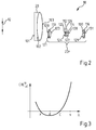
- the Fig. 2 1 shows the first optics assembly 18 in the optics system of the surgical microscope 10.
- the microscope main objective system 20 is a cemented member having the optically active surfaces 101, 102 and 103.
- the afocal zoom system 22r has four members 110, 112, 114, 116.
- the members 110, 116 of the zoom system 22r have a positive refractive power and are each designed as cemented members.
- the members 112, 114 in the afocal zoom system 22r are arranged displaceably.
- the member 112 is also embodied here as a cemented member.
- the zoom system 22r has the optically effective areas 120, 121, 123, 124, 125, 126, 127, 128, 129, 130 and 131.
- FIG. 12 shows the C-line wavelength dependent wavelength ⁇ (x-line) chromatic length error CHL 18 xC of this first optical assembly in the optical system of the surgical microscope.
- ⁇ xC is the slope of the C-line normal line for the light of wavelength x
- ⁇ xC is the distance of a specific lens i lens from this normal line
- y i is the marginal beam heights
- ⁇ i the refractive powers of the lenses referred i.
- CHL sC CHL dC ⁇ sC ⁇ dC ⁇ - 5 That is, the color errors for the near infrared and infrared are about 5 times as large as in the visible spectral range in the optical assembly 18, but the sign of these color errors is opposite to the sign of the color aberrations in the visible spectral range.
- the second optical assembly 24 in the optical system of the surgical microscope 10 serves to reduce the chromatic aberration of the image of the object region in the near infrared and infrared supplied to the color camera 26.
- the near infrared and infrared color aberrations of the optical assembly 18 are affected by the chromatic aberration the optical assembly 24 is at least partially canceled in the near infrared and infrared.
- the combination of the optical assembly 18 with the optical assembly 24 in the optical system of the surgical microscope 10 can then provide the color camera 26 with an image that is also in the visible spectral range has no color errors.
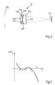
- the Fig. 4 shows the second optical assembly 24 in the optical system of the surgical microscope 10.
- the optical assembly 24 has a positive refractive power. It contains three lenses 200, 202 and 204.
- the lenses 200, 202 form a cemented member that has a positive refractive power.
- the refractive power of the lens 204 is positive.
- the lenses 200 and 204 are made of a lens material whose partial dispersion is anomalous in the visible spectral range.
- the lens 202 in the cemented member consists of one of the above-mentioned, suitable for the material of the positive lens material.
- the optics assembly 24 has the optically active surfaces 206, 207, 208, 209, and 210.
- the Fig. 5 shows the C-line-related color longitudinal error depending on the wavelength ⁇ of the light (x-line) CHL xC 24 of this second optical assembly 24 in the optical system of the surgical microscope 10.
- CHL sC . Apo 1 2 ⁇ y 0 2 ⁇ ⁇ ⁇ ⁇ P sC ⁇ v
- y 0 is the marginal ray height
- ⁇ are the refractive power of the two-membered Apochromaten.
- the size ⁇ P sC describes the difference between the relative partial dispersions of the two glass types used in the wavelength range between the s line and the C line
- the size ⁇ v describes the difference in the Abbemit of the two glasses.
- the values of the size ⁇ P sC / ⁇ v for some of the above glass pairs vary between +0.00051 and + 00042.
- the fluctuation of the values ⁇ P sC / ⁇ v for different types of glass exploits the invention so as to at least partially compensate for the longitudinal chromatic aberration CHL xC of the first optical assembly 18 by suitably selecting the glass types of the lenses 200, 202, 204 in the optical assembly 24.
- a derivative with a sign opposite to the sign of the longitudinal chromatic aberration of the first optical subassembly is set for this purpose.
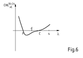
- the Fig. 6 shows the resulting color longitudinal error CHL xC 18 + 24 the first optical assembly 18 and the second optical assembly 24 in response to the wavelength ⁇ of the light.
- the second optical subassembly 24 thus compensates for the longitudinal chromatic aberration of the first optical subassembly 18 except for a residual error which does not affect the imaging of the specimen area 12 with light in the infrared spectral range on the image sensor of the camera.
- Table optical module 18 Optically effective surface Radius r / mm Thickness or air distance d / mm Free diameter d F / mm Medium (glass type) 12 object 195154 25 AIR 101 187.4 2 25 BAF3 102 75.6 8th 25 CAF2 103 -111.5 12407 AIR 120 32,181 1.2 12 S-NBH8 121 16404 2.2 12 S-PHM53 123 -180.98 0986 12 AIR 124 -19,376 1.4 7 N-SF6 125 -9,183 1 7 N-SK16 126 41591 1.6 7 AIR 127 -41,591 1 7 N-SK16 128 41591 29808 7 AIR 129 180.98 2.2 12 S-PHM53 130 -16,404 1.2 12 S-NBH8 131 -32,181 2 AIR Optically effective surface Radius r
- the lens material for the lenses of anomalous partial dispersion in the second optical assembly basically also the glasses N-FK58, N-FK51A, N-PK52A, N-PK51 from Schott, the glasses S-FPL53, S-FPL-51 , S-FPL51Y, S-FPM3 or also S-FPM2 from Ohara, or glasses with optical properties which correspond to the optical properties of the aforementioned glasses and which have an anomalous partial dispersion.
- the microscope main objective system 20 in the operation microscope 10 described above may basically also be designed as a focusable microscope main objective.
- the design of the optical assembly 24 according to the table reproduced above ensures that even when focusing the microscope main objective in the image planes 27a, 27b and 27c respectively an image of the object region 12 is generated, not only for the light in the visible spectral range, but also for the near infrared light does not lose focus without the need for a displacement of the optical assembly 24 as a whole or the lenses in this optical assembly in the beam path 16r.
- the invention relates to an optical system for imaging an object region 12 with a optical beam path 16r, 16r 'in an image plane 27a, 27b, 27c of an image acquisition system.
- the optical system includes a first optical subassembly 18 penetrated by the optical beam path 16r and a second optical subassembly 24 disposed on the side of the first optical subassembly 18 in the optical beam path 16r.
- the second optical subassembly 24 is 625 nm in the wavelength range of the light ⁇ ⁇ ⁇ 850 nm occurring longitudinal chromatic aberration of the first optical assembly 18 at least partially compensating system formed.
Landscapes
- Physics & Mathematics (AREA)
- General Physics & Mathematics (AREA)
- Optics & Photonics (AREA)
- Chemical & Material Sciences (AREA)
- Analytical Chemistry (AREA)
- Health & Medical Sciences (AREA)
- Toxicology (AREA)
- General Health & Medical Sciences (AREA)
- Surgery (AREA)
- Dispersion Chemistry (AREA)
- Engineering & Computer Science (AREA)
- Multimedia (AREA)
- Lenses (AREA)
- Microscoopes, Condenser (AREA)
Abstract
Description
- Die Erfindung betrifft ein Optiksystem für das Abbilden eines Objektbereichs mit einem optischen Strahlengang in einer Bildebene eines Bilderfassungssystems, mit einer von dem optischen Strahlengang durchsetzten ersten Optikbaugruppe und mit einer auf der dem Objektbereich abgewandten Seite der ersten Optikbaugruppe in dem optischen Strahlengang angeordneten zweiten Optikbaugruppe. Darüber hinaus betrifft die Erfindung ein Operationsmikroskop mit einem solchen Optiksystem.
- Unter einem Operationsmikroskop wird vorliegend ein System mit einer vorzugsweise als ein Stereomikroskop ausgebildeten Mikroskopeinheit verstanden, die an einem Stativ aufgenommen ist und die einer Beobachtungsperson das Beobachten eines Operationsbereichs mit Vergrößerung ermöglicht. Die Mikroskopeinheit kann für das Visualisieren des Operationsbereichs mit einem optischen Beobachtungsstrahlengang ausgelegt sein. Es ist jedoch auch möglich, eine Mikroskopeinheit vorzusehen, die einer Beobachtungsperson digital erfasste Bilder zur Anzeige bringt. Ein Beispiel für ein Operationsmikroskop im Sinne der Erfindung ist etwa das von der Carl Zeiss Meditec AG hergestellte und vertriebene System OPMI® Pentero®.
- Aus der
US 4,786,155 ist ein Optiksystem der eingangs genannten Art bekannt. Dieses Optiksystem ist in einem Operationsmikroskop angeordnet, das eine Einrichtung für das Visualisieren von Strukturen in dem Objektbereich mittels Licht einer Wellenlänge λ ≥ 620 nm hat. Für das Licht dieser Wellenlänge weist das menschliche Auge zwar eine vergleichsweise geringe Empfindlichkeit auf. Dieses Licht wird jedoch von dem arteriellen Blut im menschlichen Körper nur wenig gestreut bzw. absorbiert. Das Operationsmikroskop enthält eine Beleuchtungseinrichtung, mit der Licht bereitgestellt werden kann, das im Roten und im Infraroten Spektralbereich liegt. In dem Operationsmikroskop gibt es auf der dem Objektbereich abgewandten Seite eines afokalen Vergrößerungssystems oberhalb des Mikroskop-Hauptobjektivs in dem linken und rechten Beobachtungsstrahlengang einen Strahlteiler, der das Beobachtungslicht zu einer Kamera führt, mit der Licht im roten und infraroten Spektralbereich detektiert werden kann. Das Optiksystem in dem Operationsmikroskop enthält eine erste Optikbaugruppe mit einem afokalen Vergrößerungssystem. Dieses Optiksystem weist eine zweite Optikbaugruppe auf, die eine Objektivfunktion hat und die einen die erste Optikbaugruppe durchsetzenden Strahlengang aus einem Objektbereich auf den Bildsensor der Kamera führt. - Insbesondere für das Untersuchen von Strukturen in einem Objektbereich mit fluoreszierenden Farbstoffen ist es bei Operationsmikroskopen wünschenswert, dass mit einem Bilderfassungssystem nicht nur das sichtbare Licht erfasst werden kann, sondern auch Licht aus dem Infraroten Spektralbereich.
- Herkömmliche Operationsmikroskope weisen hierzu ein Bilderfassungssystem mit unterschiedlichen Kameras auf, die auf den sichtbaren und infraroten Spektralbereich abgestimmt sind (siehe z. B.
DE 10 2006 006 014 A1 ). - Aufgabe der Erfindung ist es, ein Optiksystem zu schaffen, das sich zum Einsatz in einem Operationsmikroskop eignet und mit dem bei gleichem Objektabstand, d.h. bei ein und demselben Abstand des Optiksystems von dem Objektbereich das Bild des Objektbereichs nicht nur im sichtbaren, sondern auch im infraroten Spektralbereich einem Bilderfassungssystem mit einer guten Abbildungsqualität zugeführt werden kann.
- Diese Aufgabe wird mit dem in Anspruch 1 angegebenen Optiksystem gelöst. Vorteilhafte Weiterbildungen der Erfindung sind in den abhängigen Ansprüchen angegeben.
- Die Erfindung beruht auf dem Gedanken, dass die in Operationsmikroskopen eingesetzten Optikbaugruppen, insbesondere Optikbaugruppen mit einem Mikroskop-Hauptobjektiv und mit einem Zoomsystem in der Regel Achromate sind. Damit wird sichergestellt, dass die Fokusablage für Licht, dessen Wellenlänge im roten Wellenlängenbereich liegt (λ≈ 640 nm), und für Licht, dessen Wellenlänge im blauen Wellenlängenbereich liegt (λ≈ 480 nm), entsprechend der Norm ISO/FDIS 19012-2 kleiner oder gleich der Schärfentiefe δ = nλ/2NA2 der Optikbaugruppe ist, wobei n der Brechungsindex des Mediums im Objektraum (in Luft gilt: n = 1), NA die objektseitige numerische Apertur, und A= 480 nm oder A= 640 nm ist.
- Solche Achromate haben jedoch in Bezug auf die vorstehend angegebenen Wellenlängen für das im Infraroten Spektralbereich liegende Licht, z. B. für das Licht der Wellenlänge λ = 850 nm einen erheblichen Farblängs- und auch Farbquerfehler.
- Um diese Farblängs- und Farbquerfehler zu verringern, schlägt die Erfindung vor, dass die zweite Optikbaugruppe in dem Optiksystem als ein in dem Wellenlängenbereich des Lichts 625 nm ≤ 850 nm auftretende Farblängsfehler der ersten Optikbaugruppe wenigstens teilweise kompensierendes System ausgebildet ist. Mit dieser Maßnahme lässt sich erreichen, dass der Objektbereich mittels des Optiksystems auch mit Licht untersucht werden kann, das im nahen infraroten und infraroten Spektralbereich liegt, ohne dass hierfür optische Baugruppen in dem Optiksystem auf langen Verlagerungswegen verstellt werden müssen. Insbesondere lässt sich mit dieser Maßnahme erreichen, dass das Verändern des Abstands des Optiksystems von dem Objektbereich bzw. ein Nachfokussieren des Optiksystems nicht dazu führt, dass das dem Bilderfassungssystem zugeführte Bild des Objektbereichs in dem Wellenlängenbereich des Lichts 625 nm ≤ λ ≤ 850 nm gegenüber einem Bild des Objektbereichs mit in dem sichtbaren Spektralbereich liegenden Licht an Schärfe verliert.
- Die zweite Optikbaugruppe in dem Optiksystem kann dabei eine positive Brechkraft haben. Insbesondere kann die zweite Optikbaugruppe ein Objektiv sein, z. B. ein Objektiv für eine Farbkamera, das eine Abbildung des Objektbereichs in der Bildebene des Bilderfassungssystems bewirkt.
- Indem die zweite Optikbaugruppe wenigstens eine in dem optischen Strahlengang relativ zu der Bildebene des Bilderfassungssystems verlagerbare Linse enthält, ist es möglich, von der Wellenlänge des für das Beobachten des Objektbereichs eingesetzten Lichts abhängige Fehler der Abbildung in der Bildebene des Bilderfassungssystems auszugleichen.
- Um von der Wellenlänge des für das Beobachten des Objektbereichs eingesetzten Lichts abhängige Fehler der Abbildung in der Bildebene des Bilderfassungssystems auszugleichen, ist es auch möglich, in dem Optiksystem eine Verlagerbarkeit der zweite Optikbaugruppe als Ganzes für das Einstellen der optischen Weglänge des optischen Strahlengangs aus dem Objektbereich in die Bildebene des Bilderfassungssystems vorzusehen.
- Erfindungsgemäß kann die zweite Optikbaugruppe eine erste Linse positiver Brechkraft sowie eine zweite Linse negativer Brechkraft und eine dritte Linse positiver Brechkraft aufweisen. Die erste Linse positiver Brechkraft und die zweite Linse negativer Brechkraft können dabei zu einem Kittglied zusammengefasst sein. Die erste Linse der zweiten Optikbaugruppe ist dann möglichst der ersten Optikbaugruppe in dem optischen Strahlengang zugewandt. Die dritte Linse der zweiten Optikbaugruppe ist hier bevorzugt auf der der Bildebene des Bilderfassungssystems zugewandten Seite in dem optischen Strahlengang angeordnet. Die beiden Linsen mit positiver Brechkraft bestehen dabei bevorzugt aus einem Material mit einer anomalen Teildispersion.
- Die Gläser der Linsen mit positiver Brechkraft in der zweiten Optikbaugruppe eines erfindungsgemäßen Optiksystems liegen jeweils abseits der sogenannten Normalgeraden.
- Erfindungsgemäße können die beiden Linsen mit positiver Brechkraft insbesondere aus den Gläsern N-FK58, N-FK51A, N-PK52A, N-PK51 der Firma Schott, aus den Gläsern S-FPL53, S-FPL-51, S-FPL51Y, S-FPM3 oder auch S-FPM2 der Firma Ohara bestehen, oder Gläser mit optischen Eigenschaften, die den optischen Eigenschaften der vorgenannten Gläser entsprechen und die eine anomale relative Teildispersion haben.
- Die Linse mit negativer Brechkraft in der zweiten Optikbaugruppe besteht günstiger Weise aus einem Material mit geringerer Abbezahl, aber einer möglichst ähnlichen relativen Teildispersion wie sie in den Positivlinsen auftritt. In einem erfindungsgemäßen Optiksystem kann die Linse mit negativer Brechkraft in der zweiten Optikbaugruppe insbesondere aus dem Glas N-KZFS2, N-BK7 oder N-SK11 bestehen.
- Vorteilhafte Glaskombinationen für die beiden Linsen mit positiver Brechkraft einerseits und die Linse mit negativer Brechkraft andererseits in der zweiten Optikbaugruppe sind insbesondere: S-FPL51/N-KZFS2, S-FPL53/N-BK7 oder N-PK51/N-SK11. Die Gläser der Linse mit negativer Brechkraft in der zweiten Optikbaugruppe in einem erfindungsgemäßen Optiksystem können, sie müssen aber nicht zwingend eine anomale Teildispersion haben. Die Gläser der Linse mit negativer Brechkraft in der zweiten Optikbaugruppe in einem erfindungsgemäßen Optiksystem können somit auch in der Nähe der Normalgeraden liegen.
- Die Erfindung schlägt insbesondere vor, dass die Differenzen der Teildispersionen der beiden Glassorten ΔPdC und die Differenzen der Abbezahlen Δv der beiden Glassorten zueinander in einem Verhältnis |ΔPdC /Δv| stehen, für das gilt |ΔPdC /Δv| ≤ 0,1‰, vorzugsweise |ΔPdC /Δv| ≤ 0,03‰.
- Die erste Optikbaugruppe in dem Optiksystem ist ein vorzugsweise für das Licht der Wellenlänge λ≈656 nm und das Licht der Wellenlänge λ≈486 nm korrigiertes achromatisches System. Die erste Optikbaugruppe kann aber auch ein apochromatisches System sein, das vorzugsweise für das Licht der Wellenlänge λ≈656 nm und das Licht der Wellenlänge λ≈486 nm sowie das Licht der Wellenlänge λ≈588 nm korrigiert ist. Die erste Optikbaugruppe kann insbesondere ein afokales Zoomsystem enthalten.
- Erfindungsgemäß ist die zweite Optikbaugruppe in dem Optiksystem ein vorzugsweise für das Licht der Wellenlänge λ≈486 nm, λ≈588 nm und λ≈656 nm korrigierter Apochromat oder ein Semiapochromat.
- Unter einem Semiapochromat versteht die Erfindung ein Optiksystem, das eine positive Brechkraft hat, bei dem die Fokusablage für Licht, dessen Wellenlänge im roten Wellenlängenbereich liegt (λ≈ 640 nm), und für Licht, dessen Wellenlänge im blauen Wellenlängenbereich liegt (λ≈ 480 nm), sowie für Licht, dessen Wellenlänge Wellenlänge im grünen Wellenlängenbereich liegt (λ≈ 546 nm), entsprechend der Norm ISO/FDIS 19012-2 kleiner oder gleich dem 2,5-fachen der Schärfentiefe δ = nλ/2NA2 ist, wobei n der Brechungsindex des Mediums im Objektraum, NA die objektseitige numerische Apertur, und λ≈ 480 nm oder λ≈ 546 nm oder λ≈ 640 nm ist.
- Unter einem Apochromat versteht die Erfindung ein Optiksystem, das eine positive Brechkraft hat, bei dem die Fokusablage für Licht, dessen Wellenlänge im roten Wellenlängenbereich liegt (λ≈ 640 nm), und für Licht, dessen Wellenlänge im blauen Wellenlängenbereich liegt (λ≈ 480 nm), sowie für Licht, dessen Wellenlänge Wellenlänge im grünen Wellenlängenbereich liegt (λ≈ 546 nm), entsprechend der Norm ISO/FDIS 19012-2 kleiner oder gleich der Schärfentiefe δ = nλ/2NA2 ist, wobei n der Brechungsindex des Mediums im Objektraum, NA die objektseitige numerische Apertur, und λ≈ 480 nm oder λ≈ 546 nm oder λ≈ 640 nm ist.
- Die Erfindung erstreckt sich auch auf ein Operationsmikroskop, das ein vorstehend angegebenes Optiksystem enthält. Von Vorteil ist es, wenn das Operationsmikroskop eine als eine 3-Chip-Kamera ausgebildete Farbkamera mit in der Bildebene des Bilderfassungssystems angeordneten Bildsensoren aufweist. Damit ist es möglich, mit der Farbkamera den Objektbereich des Operationsmikroskops mit Licht zu erfassen, dessen Wellenlänge im sichtbaren und infraroten Spektralbereich liegt. Die Erfindung erstreckt sich auch auf ein Operationsmikroskop mit einer Beleuchtungseinrichtung, die einen Beleuchtungsstrahlengang bereitstellt, der für das Anregen der Fluoreszenz eines Farbstoffs in dem Objektbereich dient und der durch ein Filtersystem für das Ausfiltern von Licht geführt werden kann, dessen Wellenlänge der Wellenlänge des Fluoreszenzlichts des fluoreszierenden Farbstoffs entspricht, das dann der Kamera in dem Operationsmikroskop detektiert wird.
- Nachfolgend werden vorteilhafte Ausführungsbeispiele der Erfindung beschrieben, die in den Zeichnungen schematisch dargestellt sind.
- Es zeigen:
- Fig. 1
- ein Operationsmikroskop mit einem Optiksystem für Visualisieren eines Objektbereichs in Okulareinblicken und das Abbilden des Objektbereichs in einer Bildebene eines Bilderfassungssystems mit einem optischen Strahlengang;
- Fig. 2
- eine erste Optikbaugruppe in dem Optiksystem des Operationsmikroskops, die ein Mikroskop-Hauptobjektivsystem und ein afokales Zoomsystem enthält;
- Fig. 3
- einen von der Wellenlänge λ des Lichts abhängigen Farblängsfehler dieser ersten Optikbaugruppe in dem Optiksystem des Operationsmikroskops;
- Fig. 4
- eine als ein Kameraobjektiv ausgebildete zweite Optikbaugruppe in dem Optiksystem des Operationsmikroskops;
- Fig. 5
- einen von der Wellenlänge λ des Lichts abhängigen Farblängsfehler der zweiten Optikbaugruppe in dem Optiksystem; und
- Fig. 6
- einen resultierenden Farblängsfehler der ersten und zweiten Optikbaugruppe in Abhängigkeit von der Wellenlänge λ des Lichts.
- Das in der
Fig. 1 gezeigte Operationsmikroskop 10 ermöglicht einer Beobachtungsperson das vergrößerte Betrachten eines Objektbereichs 12 in einem linken und rechten Okulareinblick 14l, 14r eines Binokulartubus 15 mit einem stereoskopischen optischen Strahlengang 16l, 16r. In dem Operationsmikroskop 10 wird das Licht aus dem Objektbereich 12 durch ein Optiksystem geführt, das eine in einem Mikroskopgrundkörper 17 angeordnete erste Optikbaugruppe 18 mit einem Mikroskop-Hauptobjektivsystem 20 und ein afokales Zoomsystem 22r enthält und das eine zweite Optikbaugruppe 24 hat, die als das Kameraobjektiv eines Bilderfassungssystems in Form einer Farbkamera 26 mit Bildebenen 27a, 27b, 27c wirkt, der das Licht aus dem Strahlengang 16r über einen Strahlteiler 28 zugeführt wird. In den Bildebenen 27a, 27b, 27c der Farbkamera 26 gibt es eine Teilerprismenanordnung 25 und unterschiedliche Bildsensoren 29a, 29b, 29c, die dazu dienen, das unterschiedliche, im roten, grünen und blauen Spektralbereich liegende Licht zu erfassen. Der für das Erfassen von Licht im roten Spektralbereich ausgelegte Bildsensor 29a ermöglicht auch das Erfassen von Licht, dessen Wellenlänge im nahen infraroten und infraroten Spektralbereich liegt, d.h. Licht der Wellenlänge in dem Bereich 0,7 µm bis 5 µm und Licht, dessen Wellenlänge 5µm bis 50 µm beträgt. - Alternativ hierzu ist es insbesondere auch möglich, die Teilerprismenanordnung 25 so auszulegen, dass mit dem Bildsensor 29c, der für das Erfassen von Licht im blauen Spektralbereich ausgelegt ist, auch das Licht erfasst werden kann, dessen Wellenlänge im nahen infraroten und infraroten Spektralbereich liegt.
- Der Beobachtungsstrahlengang 16l in dem Operationsmikroskop durchsetzt ein Zoomsystem 22l, das dem Aufbau des Zoomsystems 22r entspricht.
- Das Operationsmikroskop 10 ist an einem Stativ (nicht gezeigt) aufgenommen, das verstellbare Gelenkarme hat. An dem Stativ kann das Operationsmikroskop 10 über dem Objektbereich 12 durch Verstellen der Gelenkarme verlagert werden.
- Das Operationsmikroskop 10 enthält eine Beleuchtungseinrichtung 30 mit einer Lichtquelle 32 und einer von dem Licht der Lichtquelle 32 durchsetzbaren Beleuchtungsoptik 34, die einen Beleuchtungsstrahlengang 36 bereitstellt, mit dem der Objektbereich 12 beleuchtet werden kann.
- Die Beleuchtungseinrichtung 30 ist dazu ausgelegt, einen oder mehrere Farbstoffe wie z. B. den Farbstoff Indocyaningrün (ICG), den Farbstoff 5ALA oder den Farbstoff Protoporphyrin IX zu Fluoreszenz anzuregen. Hierzu wird mit der Lichtquelle 32 der Beleuchtungseinrichtung 30 Licht bereitgestellt, dessen Wellenlänge im blauen Spektralbereich liegt. Um zu vermeiden, dass in dem Beleuchtungsstrahlengang 36 Licht zu dem Objektbereich 12 geführt wird, dessen Wellenlänge der Wellenlänge des Lichts des in dem Objektbereich 12 angeordneten zu Fluoreszenz angeregten Farbstoffs entspricht, gibt es in der Beleuchtungseinrichtung 30 ein Fluoreszenzanregungsfilter 40, das entsprechend dem Doppelpfeil 38 in den Beleuchtungsstrahlengang 36 eingebracht werden kann um den Spektralbereich des Beleuchtungslichts auszufiltern, der beim Fluoreszieren eines zu Fluoreszenz angeregten Farbstoffs in dem Objektbereich 12 freigesetzt wird.
- Damit einer Beobachtungsperson und der Farbkamera 26 im Fluoreszenzbetriebsmodus des Operationsmikroskops 10 ausschließlich das von einem fluoreszierenden Farbstoff in dem Objektbereich 12 freigesetzte Fluoreszenzlicht zugeführt werden kann, enthält das Optiksystem in dem Operationsmikroskop 10 verstellbare Filterelemente 42, die entsprechend dem Doppelpfeil 44 auf der dem Objektbereich abgewandten Seite der Zoomsysteme in den steresokopischen Beobachtungsstrahlengängen 16l, 16r angeordnet werden können. Mittels der Filterelemente 42 kann sichergestellt werden, dass das Licht der Wellenlänge des die Fluoreszenz anregenden Lichts nicht zu den Okulareinblicken 14l, 14r des Binokulartubus 15 und zu der Farbkamera 26 gelangt.
- Die
Fig. 2 zeigt die erste Optikbaugruppe 18 in dem Optiksystem des Operationsmikroskops 10. Das Mikroskop-Hauptobjektivsystem 20 ist ein Kittglied mit den optisch wirksamen Flächen 101, 102 und 103. Das afokale Zoomsystem 22r hat vier Glieder 110, 112, 114, 116. Die Glieder 110, 116 des Zoomsystems 22r haben eine positive Brechkraft und sind jeweils als Kittglieder gestaltet. Die Glieder 112, 114 in dem afokalen Zoomsystem 22r sind verlagerbar angeordnet. Das Glied 112 ist hier ebenfalls als ein Kittglied ausgeführt. Das Zoomsystem 22r hat die optisch wirksamen Flächen 120, 121, 123, 124, 125, 126, 127, 128, 129, 130 und 131. - Die Optikbaugruppe 18 ist ein Achromat, der in Bezug auf das Licht der Wellenlänge A= 656 nm (C-Linie) den Farblängsfehler CHL der Wellenfront für das Licht der Wellenlänge A= 486 nm (F-Linie) vollständig kompensiert, d. h. CHL18 FC = 0.
- Die
Fig. 3 zeigt den auf die C-Linie bezogenen, von der Wellenlänge λ des Lichts (x-Linie) abhängigen Farblängsfehler CHL18 xC dieser ersten Optikbaugruppe in dem Optiksystem des Operationsmikroskops. - Dem Aufbau des Optiksystems in dem Operationsmikroskop 10 liegt die Überlegung zugrunde, dass sich der auf die C-Linie bezogene, von einer beliebigen Wellenlänge des Lichts (x-Linie) abhängige Farblängsfehler CHL18 xC der Wellenfront in Bezug auf die C-Linie in guter Näherung wie folgt abschätzen lässt:

- Die Erfinder haben herausgefunden, dass, wenn in der Optikbaugruppe 18 für die Achromatisierung ausschließlich Normalgläser eingesetzt werden (d. h. βxC,i = 0), die auf die C-Linie Farblängsfehler für das Licht der Wellenlänge A= 588 nm (d-Linie) und A= 850 nm (s-Linie) mit


- Die zweite Optikbaugruppe 24 in dem Optiksystem des Operationsmikroskops 10 dient dazu, den Farbfehler des der Farbkamera 26 zugeführten Bilds des Objektbereichs im nahen Infraroten und im Infraroten zu verringern.
- Dies wird dadurch erreicht, dass die Farbfehler der Optikgruppe 24 vorzugsweise für Licht der Wellenlänge A= 656 nm (C-Linie), A= 588 nm (d-Linie) und A= 486 nm (F-Linie) gleichzeitig vollständig kompensiert sind. Der Farbfehler der Optikbaugruppe 24 für die Wellenlänge A= 850 nm (s-Linie) besitzt dann nämlich ein entgegengesetztes Vorzeichen zum entsprechenden Farbfehler der Optikbaugruppe 18. Das hat zur Folge, dass der Farbfehler im nahen Infraroten und im Infraroten der Optikbaugruppe 18 durch den Farbfehler der Optikbaugruppe 24 im nahen Infraroten und im Infraroten wenigstens teilweise aufgehoben wird. Weil die Optikbaugruppe 18 und die Optikbaugruppe 24 für das Licht im sichtbaren Spektralbereich jeweils vollständig kompensiert sind, kann dann durch die Kombination der Optikbaugruppe 18 mit der Optikbaugruppe 24 in dem Optiksystem des Operationsmikroskops 10 der Farbkamera 26 ein Bild zugeführt werden, das auch im sichtbaren Spektralbereich keine Farbfehler hat.
- Die
Fig. 4 zeigt die zweite Optikbaugruppe 24 in dem Optiksystem des Operationsmikroskops 10. Die Optikbaugruppe 24 hat eine positive Brechkraft. Sie enthält drei Linsen 200, 202 und 204. Die Linsen 200, 202 bilden ein Kittglied, das eine positive Brechkraft hat. Die Brechkraft der Linse 204 ist positiv. Die Linsen 200 und 204 bestehen aus einem Linsenmaterial, dessen Teildispersion in dem sichtbaren Spektralbereich anomal ist. Die Linse 202 in dem Kittglied besteht aus einem der oben erläuterten, zum Material der Positivlinsen passenden Material. Die Optikbaugruppe 24 hat die optisch wirksamen Flächen 206, 207, 208, 209 und 210. Sie ist ein zweigliedriger Apochromat, der in Bezug auf das Licht der Wellenlänge A= 656 nm (C-Linie) den Farblängsfehler CHL 24 der Wellenfront für das Licht der Wellenlänge A= 486 nm (F-Linie) und für das Licht der Wellenlänge A= 588 nm (d-Linie) vollständig kompensiert, d. h.

- Die
Fig. 5 zeigt den auf die C-Linie bezogenen, von der Wellenlänge λ des Lichts (x-Linie) abhängigen Farblängsfehler
- Die Erfinder haben herausgefunden, dass der Restfehler des zweigliedrigen Apochromaten ins nahe Infrarote bei Licht der Wellenlänge A= 852 nm (s-Linie) in guter Näherung wie folgt abgeschätzt werden kann:

- Wie sich der nachfolgenden Tabelle entnehmen lässt, schwanken die Werte der Größe ΔPsC/Δv für einige der o.g. Glaspaare zwischen +0,00051 und + 00042.
Tabelle zu Werten der Größe ΔPsC/Δv für unterschiedliche Glaspaare Glaspaar ΔP Δv ΔP/Δv sC sC S-FPL51 / N-KZFS2 0,01410 27,54 0,000512 S-FPL53 / N-BK7 0,01290 30,78 0,000419 N-PK51 / N-SK11 0,00760 16,18 0,000470 - Die Schwankungen der Werte der Größe ΔPsC/Δv für unterschiedliche Glassorten nutzt die Erfindung aus, um damit durch eine geeignete Auswahl der Glassorten der Linsen 200, 202, 204 in der Optikbaugruppe 24 den Farblängsfehler CHLxC der ersten Optikbaugruppe 18 wenigstens teilweise zu kompensieren. Für den Farblängsfehler der zweiten Optikbaugruppe in dem infraroten Spektralbereich wird hierfür ein Vorhalt mit einem zu dem Vorzeichen des Farblängsfehlers der ersten Optikbaugruppe entgegengesetzten Vorzeichen eingestellt.
- Die
Fig. 6 zeigt den resultierenden Farblängsfehler
- In dem Optiksystem des Operationsmikroskops 10 kompensiert damit die zweite Optikbaugruppe 24 den Farblängsfehler der ersten Optikbaugruppe 18 bis auf ein einen Restfehler, der sich für das Abbilden des Objektbereichs 12 mit Licht im infraroten Spektralbereich auf dem Bildsensor der Kamera nicht auswirkt.
- Ein Designbeispiel für die erste Optikbaugruppe 18 und die zweite Optikbaugruppe 24 in dem Optiksystem des Operationsmikroskops 10 ist in den nachfolgenden Tabellen wiedergegeben:
Tabelle Optikbaugruppe 18 Optisch wirksame Fläche Radius r/mm Dicke bzw. Luftabstand d/mm Freier Durchmesser dF/mm Medium (Glasart) 12 Objekt 195.154 25 AIR 101 187.4 2 25 BAF3 102 75.6 8 25 CAF2 103 -111.5 12.407 AIR 120 32.181 1.2 12 S-NBH8 121 16.404 2.2 12 S-PHM53 123 -180.98 0.986 12 AIR 124 -19.376 1.4 7 N-SF6 125 -9.183 1 7 N-SK16 126 41.591 1.6 7 AIR 127 -41.591 1 7 N-SK16 128 41.591 29.808 7 AIR 129 180.98 2.2 12 S-PHM53 130 -16.404 1.2 12 S-NBH8 131 -32.181 2 AIR Tabelle Optikbaugruppe 24 Optisch wirksame Fläche Radius r/mm Dicke bzw. Luftabstand d/mm Freier Durchmesser dF/mm Medium (Glasart) 205 Pupille 10-60 12 AIR 206 33.978 3 12 S-FPL51 207 -18.260 1.5 12 N-KZFS2 208 56.630 0.1 12 AIR 209 25.489 2 12 S-FPL51 210 732.328 46.65 12 AIR 211 Bild Dabei gilt: Medium (Glasart) Brechzahl ne bei 546nm Abbezahl ve bei 546nm BAF3 1.585650 46.17 CAF2 1.434966 94.69 S-NBH8 1.725384 34.47 S-PHM53 1.605199 65.15 N-SF6 1.812659 25.16 N-SK16 1.622863 60.08 S-FPL51 1.498454 81.14 N-KZSF2 1.560823 53.83 AIR 1 - - Es sei bemerkt, dass als Linsenmaterial für die Linsen anomaler Teildispersion in der zweiten Optikbaugruppe grundsätzlich auch die Gläser N-FK58, N-FK51A, N-PK52A, N-PK51 der Firma Schott, die Gläser S-FPL53, S-FPL-51, S-FPL51Y, S-FPM3 oder auch S-FPM2 der Firma Ohara, oder Gläser mit optischen Eigenschaften, die den optischen Eigenschaften der vorgenannten Gläser entsprechen und die eine anomale Teildispersion haben.
- Zu bemerken ist, dass das Mikroskop-Hauptobjektivsystem 20 in dem vorstehend beschriebenen Operationsmikroskop 10 grundsätzlich auch als ein fokussierbares Mikroskop-Hauptobjektiv ausgebildet sein kann. Die Auslegung der Optikbaugruppe 24 nach der vorstehend wiedergegebenen Tabelle gewährleistet, dass auch bei Fokussieren des Mikroskop-Hauptobjektivs in den Bildebenen 27a, 27b und 27c jeweils ein Bild des Objektbereichs 12 erzeugt wird, das nicht nur für das Licht im sichtbaren Spektralbereich, sondern auch für das Licht im nahen Infraroten nicht an Schärfe verliert, ohne dass es hierfür einer Verlagerung der Optikbaugruppe 24 als Ganzes oder der Linsen in dieser Optikbaugruppe in dem Strahlengang 16r bedarf.
- Zusammenfassend ist insbesondere folgendes festzuhalten: Die Erfindung betrifft ein Optiksystem für das Abbilden eines Objektbereichs 12 mit einem optischen Strahlengang 16r, 16r' in einer Bildebene 27a, 27b, 27c eines Bilderfassungssystems. Das Optiksystem enthält eine von dem optischen Strahlengang 16r durchsetzte erste Optikbaugruppe 18 und eine auf der dem Objektbereich 12 abgewandten Seite der ersten Optikbaugruppe 18 in dem optischen Strahlengang 16r angeordneten zweiten Optikbaugruppe 24. Die zweite Optikbaugruppe 24 ist als ein in dem Wellenlängenbereich des Lichts 625 nm ≤ λ ≤ 850 nm auftretende Farblängsfehler der ersten Optikbaugruppe 18 wenigstens teilweise kompensierendes System ausgebildet.
-
- 10
- Operationsmikroskop
- 12
- Objektbereich
- 14l
- Okulareinblick links
- 14r
- Okulareinblick rechts
- 15
- Binokulartubus
- 16l
- Strahlengang links
- 16r
- Strahlengang rechts
- 16r'
- Strahlengang rechts
- 17
- Mikroskopgrundkörper
- 18
- erste Optikbaugruppe
- 20
- Mikroskop-Hauptobjektivsystem
- 22l, 22r
- Zoomsystem
- 24
- zweite Optikbaugruppe
- 25
- Teilerprismenanordnung
- 26
- Farbkamera
- 27a, b, c
- Bildebenen
- 28
- Strahlteiler
- 29a, b, c
- Bildsensoren
- 30
- Beleuchtungseinrichtung
- 32
- Lichtquelle
- 34
- Beleuchtungsoptik
- 36
- Beleuchtungsstrahlengang
- 38
- Doppelpfeil
- 40
- Fluoreszenzanregungsfilter
- 42
- Filterelement
- 44
- Doppelpfeil
- 101, 102, 103 optisch wirksame Fläche
- 110, 112, 114, 116 Glied
- 120, 121, 123, 124, 125,126, 127, 128, 129, 130, 131 optisch wirksame Fläche
- 200, 202, 204
- Linse
- 205
- Pupille
- 206, 207, 208, 209, 210
- optisch wirksame Fläche
- 211
- Bild
Claims (15)
- Optiksystem für das Abbilden eines Objektbereichs (12) mit einem optischen Strahlengang (16r) in einer Bildebene (27a, 27b, 27c) eines Bilderfassungssystems
mit einer von dem optischen Strahlengang (16r) durchsetzten ersten Optikbaugruppe (18); und
mit einer auf der dem Objektbereich (12) abgewandten Seite der ersten Optikbaugruppe (18) in dem optischen Strahlengang (16r) angeordneten zweiten Optikbaugruppe (24),
dadurch gekennzeichnet, dass
die zweite Optikbaugruppe (24) als ein in dem Wellenlängenbereich des Lichts 625 nm ≤ λ ≤ 850 nm auftretende Farblängsfehler der ersten Optikbaugruppe (18) wenigstens teilweise kompensierendes System ausgebildet ist. - Optiksystem nach Anspruch 1, dadurch gekennzeichnet, dass die zweite Optikbaugruppe (24) eine positive Brechkraft hat.
- Optiksystem nach Anspruch 1 oder 2, dadurch gekennzeichnet, dass die zweite Optikbaugruppe (24) ein eine Abbildung des Objektbereichs (12) in der Bildebene (27a, 27b, 27c) des Bilderfassungssystems bewirkendes Objektiv ist.
- Optiksystem nach einem der Ansprüche 1 bis 3, dadurch gekennzeichnet, dass die zweite Optikbaugruppe (24) wenigstens eine in dem optischen Strahlengang (16r) relativ zu der Bildebene (27a, 27b, 27c) des Bilderfassungssystems verlagerbare Linse (200, 2,2, 204) enthält.
- Optiksystem nach Anspruch 4, gekennzeichnet durch eine verlagerbar angeordnete zweite Optikbaugruppe (24) für das Einstellen der optischen Weglänge des optischen Strahlengangs (16r) aus dem Objektbereich (12) in die Bildebene (27a, 27b, 27c) des Bilderfassungssystems.
- Optiksystem nach einem der Ansprüche 1 bis 5, dadurch gekennzeichnet, dass die zweite Optikbaugruppe (24) eine erste Linse (200) positiver Brechkraft sowie eine zweite Linse (202) negativer Brechkraft und eine dritte Linse (204) positiver Brechkraft aufweist.
- Optiksystem nach Anspruch 6, dadurch gekennzeichnet, dass die erste Linse (200) positiver Brechkraft und die zweite Linse (202) negativer Brechkraft zu einem Kittglied zusammengefasst sind.
- Optiksystem nach einem der Ansprüche 6 oder 7, dadurch gekennzeichnet, dass die erste Linse (200) der zweiten Optikbaugruppe (24) der ersten Optikbaugruppe (18) in dem optischen Strahlengang zugewandt ist.
- Optiksystem nach einem der Ansprüche 6 bis 8, dadurch gekennzeichnet, dass die dritte Linse (204) der zweiten Optikbaugruppe (24) auf der der Bildebene des Bilderfassungssystems zugewandten Seite in dem optischen Strahlengang angeordnet ist.
- Optiksystem nach einem der Ansprüche 6 bis 9, dadurch gekennzeichnet, dass die erste Linse (200) der zweiten Optikbaugruppe (24) und/oder die dritte Linse (204) aus einem Linsenmaterial hergestellt ist, das eine anomale Teildispersion hat.
- Optiksystem nach einem der Ansprüche 6 bis 10, dadurch gekennzeichnet, dass die erste Linse (200) aus einem ersten Glasmaterial hergestellt ist und die zweite (202) Linse aus einem zweiten Glasmaterial hergestellt ist und die dritte Linse (204) aus dem ersten oder einem dritten Glasmaterial hergestellt ist, wobei die Differenzen ΔPdC der Teildispersionen des ersten Glasmaterials oder des dritten Glasmaterials zu der Teildispersion des zweiten Glasmaterials und die die Differenzen Δv der Abbezahlen des ersten Glasmaterials oder des dritten Glasmaterials zu der Abbezahl des zweiten Glasmaterials zueinander in einem Verhältnis |ΔPdC /Δv| stehen, für das gilt |ΔPdC /Δv| ≤ 0,1‰, vorzugsweise |ΔPdC /Δv| ≤ 0,03‰.
- Optiksystem nach einem der Ansprüche 1 bis 11, dadurch gekennzeichnet, dass die erste Optikbaugruppe (18) ein achromatisches System ist, das vorzugsweise für das Licht der Wellenlänge λ≈656 nm und das Licht der Wellenlänge λ≈486 nm korrigiert ist, oder ein apochromatisches System ist, das vorzugsweise für das Licht der Wellenlänge λ≈656 nm und das Licht der Wellenlänge λ≈486 nm sowie das Licht der Wellenlänge λ≈588 nm korrigiert ist, und/oder ein afokales Zoomsystem enthält, und/oder dass die zweite Optikbaugruppe (24) ein vorzugsweise für das Licht der Wellenlänge λ≈486 nm, λ≈588 nm und λ≈656 nm korrigierter Apochromat oder Semiapochromat ist.
- Operationsmikroskop, gekennzeichnet durch ein nach einem der Ansprüche 1 bis 12 ausgebildetes Optiksystem.
- Operationsmikroskop nach Anspruch 13, gekennzeichnet durch eine als eine 3-Chip-Kamera ausgebildete Farbkamera (26) mit in der Bildebene des Bilderfassungssystems angeordneten Bildsensoren.
- Operationsmikroskop nach Anspruch 14, gekennzeichnet durch eine Beleuchtungseinrichtung (30) mit einem Beleuchtungsstrahlengang (36), der für das Anregen der Fluoreszenz eines Farbstoffs in dem Objektbereich (12) dient und der ein Filtersystem für das Ausfiltern von Licht geführt werden kann, dessen Wellenlänge der Wellenlänge des Fluoreszenzlichts des fluoreszierenden Farbstoffs entspricht.
Applications Claiming Priority (1)
| Application Number | Priority Date | Filing Date | Title |
|---|---|---|---|
| DE102015203844.0A DE102015203844A1 (de) | 2015-03-04 | 2015-03-04 | Optiksystem und Operationsmikroskop |
Publications (2)
| Publication Number | Publication Date |
|---|---|
| EP3064980A1 true EP3064980A1 (de) | 2016-09-07 |
| EP3064980B1 EP3064980B1 (de) | 2020-04-15 |
Family
ID=55299398
Family Applications (1)
| Application Number | Title | Priority Date | Filing Date |
|---|---|---|---|
| EP16154271.7A Active EP3064980B1 (de) | 2015-03-04 | 2016-02-04 | Optiksystem und operationsmikroskop |
Country Status (5)
| Country | Link |
|---|---|
| US (1) | US10330927B2 (de) |
| EP (1) | EP3064980B1 (de) |
| JP (1) | JP6735573B2 (de) |
| DE (1) | DE102015203844A1 (de) |
| ES (1) | ES2793298T3 (de) |
Families Citing this family (11)
| Publication number | Priority date | Publication date | Assignee | Title |
|---|---|---|---|---|
| DE102017107915A1 (de) | 2016-07-18 | 2018-01-18 | Carl Zeiss Meditec Ag | System zur Augentherapie mittels Gewebebearbeitung durch nichtlineare Wechselwirkung |
| CN107920188A (zh) * | 2016-10-08 | 2018-04-17 | 杭州海康威视数字技术股份有限公司 | 一种镜头及摄像机 |
| EP3538941B1 (de) | 2016-11-10 | 2025-04-23 | The Trustees of Columbia University in the City of New York | Schnelles hochauflösendes bildgebungsverfahren für grosse proben |
| DE102017105926A1 (de) | 2017-03-20 | 2018-09-20 | Carl Zeiss Microscopy Gmbh | Verfahren und Mikroskop zum Abbilden eines Objektes |
| CA3061894A1 (en) * | 2017-06-21 | 2018-12-27 | Alcon Inc. | Wide field of view, high optical power disposable retina viewing system |
| CN110398832A (zh) * | 2019-07-11 | 2019-11-01 | 长春理工大学 | 近红外和长波红外双波段显微物镜 |
| DE102021210318B3 (de) * | 2021-09-17 | 2023-03-16 | Carl Zeiss Meditec Ag | Operationsmikroskop mit einem Anschlussbereich zur Befestigung eines Schutzglasmoduls |
| JP2024064312A (ja) * | 2022-10-28 | 2024-05-14 | 株式会社ミツトヨ | 光学装置 |
| US12038630B1 (en) | 2022-11-18 | 2024-07-16 | Designs For Vision, Inc. | Telescopic image capture/recording device |
| US12332507B2 (en) * | 2022-11-18 | 2025-06-17 | Designs For Vision, Inc. | Examination/visualization/collection system with light enhancement |
| CN115644795B (zh) * | 2022-12-12 | 2024-04-09 | 图湃(北京)医疗科技有限公司 | 手术显微镜系统及手术显微镜 |
Citations (6)
| Publication number | Priority date | Publication date | Assignee | Title |
|---|---|---|---|---|
| US4786155A (en) | 1986-12-16 | 1988-11-22 | Fantone Stephen D | Operating microscope providing an image of an obscured object |
| DE102006006014A1 (de) | 2006-02-08 | 2007-09-06 | Carl Zeiss Surgical Gmbh | Mikroskopiesystem zur Beobachtung von Fluoreszenz |
| EP1892553A1 (de) * | 2006-08-25 | 2008-02-27 | Carl Zeiss Surgical GmbH | Operationsmikroskop mit Beleuchtungseinrichtung |
| EP2051051A2 (de) * | 2007-10-16 | 2009-04-22 | Cambridge Research & Instrumentation, Inc. | Spektralbildgebungssystem mit dynamischer optischer Korrektur |
| EP2199842A1 (de) * | 2008-12-17 | 2010-06-23 | Carl Zeiss Surgical GmbH | Chirurgisches Mikroskop zur Beobachtung einer Infrarot-Fluoreszenz und entsprechendes Verfahren |
| EP2202556A1 (de) * | 2007-10-22 | 2010-06-30 | Nikon Corporation | Bildformungslinse und mikroskopvorrichtung |
Family Cites Families (6)
| Publication number | Priority date | Publication date | Assignee | Title |
|---|---|---|---|---|
| US5859700A (en) * | 1995-11-22 | 1999-01-12 | Kairos Scientific, Inc. | High resolution imaging microscope (HIRIM) and uses thereof |
| DE19837135C5 (de) * | 1997-09-29 | 2016-09-22 | Carl Zeiss Meditec Ag | Afokales Zoomsystem |
| JP2007304312A (ja) * | 2006-05-11 | 2007-11-22 | Nidec Copal Corp | 色消しレンズ系 |
| US20080225409A1 (en) * | 2007-03-12 | 2008-09-18 | Christopher Carl Alexay | Wide Band Achromatic Visible to Near-Infrared Lens Design |
| DE102009044983A1 (de) | 2009-09-24 | 2011-03-31 | Carl Zeiss Microimaging Gmbh | Mikroskop |
| CA2832328C (en) | 2011-05-09 | 2019-06-18 | Ventana Medical Systems, Inc. | Spectral imaging for measurement of nuclear pathology features in cancer cells prepared for in situ analysis |
-
2015
- 2015-03-04 DE DE102015203844.0A patent/DE102015203844A1/de not_active Withdrawn
-
2016
- 2016-02-04 EP EP16154271.7A patent/EP3064980B1/de active Active
- 2016-02-04 ES ES16154271T patent/ES2793298T3/es active Active
- 2016-03-04 US US15/061,904 patent/US10330927B2/en active Active
- 2016-03-04 JP JP2016041878A patent/JP6735573B2/ja active Active
Patent Citations (6)
| Publication number | Priority date | Publication date | Assignee | Title |
|---|---|---|---|---|
| US4786155A (en) | 1986-12-16 | 1988-11-22 | Fantone Stephen D | Operating microscope providing an image of an obscured object |
| DE102006006014A1 (de) | 2006-02-08 | 2007-09-06 | Carl Zeiss Surgical Gmbh | Mikroskopiesystem zur Beobachtung von Fluoreszenz |
| EP1892553A1 (de) * | 2006-08-25 | 2008-02-27 | Carl Zeiss Surgical GmbH | Operationsmikroskop mit Beleuchtungseinrichtung |
| EP2051051A2 (de) * | 2007-10-16 | 2009-04-22 | Cambridge Research & Instrumentation, Inc. | Spektralbildgebungssystem mit dynamischer optischer Korrektur |
| EP2202556A1 (de) * | 2007-10-22 | 2010-06-30 | Nikon Corporation | Bildformungslinse und mikroskopvorrichtung |
| EP2199842A1 (de) * | 2008-12-17 | 2010-06-23 | Carl Zeiss Surgical GmbH | Chirurgisches Mikroskop zur Beobachtung einer Infrarot-Fluoreszenz und entsprechendes Verfahren |
Non-Patent Citations (3)
| Title |
|---|
| DR RALF: "Color correction in optical systems or why optical design needs fluoro-phosphate glasses", DR. RALF JEDAMZIK, 31 May 2014 (2014-05-31), XP055283941, Retrieved from the Internet <URL:http://www.schott.com/advanced_optics/english/download/schott-fluoro-phosphate-glasses-may-2014.pdf> [retrieved on 20160627] * |
| UNKNOWN: "Datasheet S-BSM16", 5 January 2004 (2004-01-05), XP055284216, Retrieved from the Internet <URL:http://www.oharacorp.com/pdf/esbsm16.pdf> [retrieved on 20160628] * |
| UNKNOWN: "Datasheet S-NBH5", 1 February 2006 (2006-02-01), XP055284224, Retrieved from the Internet <URL:http://www.ohara-inc.co.jp/en/product/optical/dl/data/esnbh05.pdf> [retrieved on 20160628] * |
Also Published As
| Publication number | Publication date |
|---|---|
| EP3064980B1 (de) | 2020-04-15 |
| DE102015203844A1 (de) | 2016-09-08 |
| US20160259163A1 (en) | 2016-09-08 |
| JP2016161946A (ja) | 2016-09-05 |
| ES2793298T3 (es) | 2020-11-13 |
| US10330927B2 (en) | 2019-06-25 |
| JP6735573B2 (ja) | 2020-08-05 |
Similar Documents
| Publication | Publication Date | Title |
|---|---|---|
| EP3064980B1 (de) | Optiksystem und operationsmikroskop | |
| EP1906225B1 (de) | Miniaturisiertes optisch abbildendes System mit hoher lateraler und axialer Auflösung | |
| DE102010033825B4 (de) | Fluoreszenzbeobachtungssystem und Filtersatz | |
| EP3058414B1 (de) | Scanmikroskop und verfahren zum bestimmung der punkt-spreiz-funktion (psf) eines scanmikroskops | |
| DE102009037841A1 (de) | Wellenfrontanalysesystem und optisches System mit Mikroskop und Wellenfrontanalysesystem | |
| DE102013105586B4 (de) | Vorrichtung zur Abbildung einer Probe | |
| EP1423746A2 (de) | Mikroskop | |
| EP1882969A1 (de) | Laser-Scanning-Mikroskop | |
| DE102017223014A1 (de) | Verfahren zur Bestimmung der Dicke einer Probenhalterung im Strahlengang eines Mikroskops | |
| DE102014008243A1 (de) | Fluoreszenbeobachtungssystem und optisches Filtersystem hierfür | |
| DE102018118352A1 (de) | Ophthalmologisches Operationsmikroskop | |
| EP1882970A1 (de) | Laser-Scanning-Mikroskop zur Fluoreszenzuntersuchung | |
| DE102018126002B4 (de) | Verfahren und Mikroskop zur Bestimmung des Brechungsindex eines optischen Mediums | |
| DE102009037366A1 (de) | Mikroskop, insbesondere zur Messung von Totalreflexions-Fluoreszenz, und Betriebsverfahren für ein solches | |
| DE102024124248A1 (de) | Mikroskop, verfahren zur bestimmung einer feldinhomogenität in einem sichtfeld eines mikroskops und mikroskopieverfahren | |
| DE102008022493A1 (de) | Vorrichtung und Verfahren zum evaneszenten Beleuchten einer Probe | |
| DE202009011701U1 (de) | Vorrichtung zum optischen Abtasten von Proben, mit einer Streuscheibe vor einem Durchlicht-Detektor | |
| DE102008028490A1 (de) | Beleuchtungsanordnung für die TIRF-Mikroskopie | |
| EP3198323B1 (de) | Vorrichtung zur abbildung einer probe | |
| EP2853933B1 (de) | Optisches Abbildungssystem | |
| WO2021151780A1 (de) | Methode zum kennzeichnen eines bereiches eines tumors | |
| DE102024206242A1 (de) | Unendlich korrigiertes Mikroskop-Objektiv für Scan-Anwendungen | |
| WO2017036893A1 (de) | Bildaufnahmeanordnung, optisches beobachtungsgerät und verfahren zum aufnehmen von bildern | |
| DE102018126009B4 (de) | Verfahren und Mikroskop zur Bestimmung der Dicke eines Deck- oder Tragglases | |
| DE4116067C2 (de) | Vorrichtung zur Beobachtung des Augenhintergrundes |
Legal Events
| Date | Code | Title | Description |
|---|---|---|---|
| PUAI | Public reference made under article 153(3) epc to a published international application that has entered the european phase |
Free format text: ORIGINAL CODE: 0009012 |
|
| AK | Designated contracting states |
Kind code of ref document: A1 Designated state(s): AL AT BE BG CH CY CZ DE DK EE ES FI FR GB GR HR HU IE IS IT LI LT LU LV MC MK MT NL NO PL PT RO RS SE SI SK SM TR |
|
| AX | Request for extension of the european patent |
Extension state: BA ME |
|
| STAA | Information on the status of an ep patent application or granted ep patent |
Free format text: STATUS: REQUEST FOR EXAMINATION WAS MADE |
|
| 17P | Request for examination filed |
Effective date: 20170222 |
|
| RBV | Designated contracting states (corrected) |
Designated state(s): AL AT BE BG CH CY CZ DE DK EE ES FI FR GB GR HR HU IE IS IT LI LT LU LV MC MK MT NL NO PL PT RO RS SE SI SK SM TR |
|
| STAA | Information on the status of an ep patent application or granted ep patent |
Free format text: STATUS: EXAMINATION IS IN PROGRESS |
|
| 17Q | First examination report despatched |
Effective date: 20180129 |
|
| RIC1 | Information provided on ipc code assigned before grant |
Ipc: G02B 27/00 20060101ALI20180621BHEP Ipc: G02B 13/14 20060101ALI20180621BHEP Ipc: G02B 21/22 20060101ALN20180621BHEP Ipc: G02B 9/16 20060101ALI20180621BHEP Ipc: G02B 21/00 20060101AFI20180621BHEP Ipc: G02B 21/16 20060101ALN20180621BHEP |
|
| RIC1 | Information provided on ipc code assigned before grant |
Ipc: G02B 13/14 20060101ALI20180712BHEP Ipc: G02B 27/00 20060101ALI20180712BHEP Ipc: G02B 9/16 20060101ALI20180712BHEP Ipc: G02B 21/16 20060101ALN20180712BHEP Ipc: G02B 21/22 20060101ALN20180712BHEP Ipc: G02B 21/00 20060101AFI20180712BHEP |
|
| GRAP | Despatch of communication of intention to grant a patent |
Free format text: ORIGINAL CODE: EPIDOSNIGR1 |
|
| RIC1 | Information provided on ipc code assigned before grant |
Ipc: G02B 27/00 20060101ALI20180725BHEP Ipc: G02B 21/00 20060101AFI20180725BHEP Ipc: G02B 21/16 20060101ALN20180725BHEP Ipc: G02B 21/22 20060101ALN20180725BHEP Ipc: G02B 9/16 20060101ALI20180725BHEP Ipc: G02B 13/14 20060101ALI20180725BHEP |
|
| STAA | Information on the status of an ep patent application or granted ep patent |
Free format text: STATUS: GRANT OF PATENT IS INTENDED |
|
| INTG | Intention to grant announced |
Effective date: 20180830 |
|
| GRAJ | Information related to disapproval of communication of intention to grant by the applicant or resumption of examination proceedings by the epo deleted |
Free format text: ORIGINAL CODE: EPIDOSDIGR1 |
|
| STAA | Information on the status of an ep patent application or granted ep patent |
Free format text: STATUS: EXAMINATION IS IN PROGRESS |
|
| INTC | Intention to grant announced (deleted) | ||
| GRAP | Despatch of communication of intention to grant a patent |
Free format text: ORIGINAL CODE: EPIDOSNIGR1 |
|
| STAA | Information on the status of an ep patent application or granted ep patent |
Free format text: STATUS: GRANT OF PATENT IS INTENDED |
|
| RIC1 | Information provided on ipc code assigned before grant |
Ipc: G02B 27/00 20060101ALI20191202BHEP Ipc: G02B 21/00 20060101AFI20191202BHEP Ipc: G02B 13/14 20060101ALI20191202BHEP Ipc: G02B 9/16 20060101ALI20191202BHEP Ipc: G02B 21/22 20060101ALN20191202BHEP Ipc: G02B 21/16 20060101ALN20191202BHEP |
|
| INTG | Intention to grant announced |
Effective date: 20200103 |
|
| GRAS | Grant fee paid |
Free format text: ORIGINAL CODE: EPIDOSNIGR3 |
|
| GRAA | (expected) grant |
Free format text: ORIGINAL CODE: 0009210 |
|
| STAA | Information on the status of an ep patent application or granted ep patent |
Free format text: STATUS: THE PATENT HAS BEEN GRANTED |
|
| AK | Designated contracting states |
Kind code of ref document: B1 Designated state(s): AL AT BE BG CH CY CZ DE DK EE ES FI FR GB GR HR HU IE IS IT LI LT LU LV MC MK MT NL NO PL PT RO RS SE SI SK SM TR |
|
| REG | Reference to a national code |
Ref country code: CH Ref legal event code: EP |
|
| REG | Reference to a national code |
Ref country code: DE Ref legal event code: R096 Ref document number: 502016009514 Country of ref document: DE |
|
| REG | Reference to a national code |
Ref country code: IE Ref legal event code: FG4D Free format text: LANGUAGE OF EP DOCUMENT: GERMAN |
|
| REG | Reference to a national code |
Ref country code: AT Ref legal event code: REF Ref document number: 1257998 Country of ref document: AT Kind code of ref document: T Effective date: 20200515 |
|
| REG | Reference to a national code |
Ref country code: NL Ref legal event code: MP Effective date: 20200415 |
|
| REG | Reference to a national code |
Ref country code: LT Ref legal event code: MG4D |
|
| PG25 | Lapsed in a contracting state [announced via postgrant information from national office to epo] |
Ref country code: LT Free format text: LAPSE BECAUSE OF FAILURE TO SUBMIT A TRANSLATION OF THE DESCRIPTION OR TO PAY THE FEE WITHIN THE PRESCRIBED TIME-LIMIT Effective date: 20200415 Ref country code: IS Free format text: LAPSE BECAUSE OF FAILURE TO SUBMIT A TRANSLATION OF THE DESCRIPTION OR TO PAY THE FEE WITHIN THE PRESCRIBED TIME-LIMIT Effective date: 20200815 Ref country code: PT Free format text: LAPSE BECAUSE OF FAILURE TO SUBMIT A TRANSLATION OF THE DESCRIPTION OR TO PAY THE FEE WITHIN THE PRESCRIBED TIME-LIMIT Effective date: 20200817 Ref country code: FI Free format text: LAPSE BECAUSE OF FAILURE TO SUBMIT A TRANSLATION OF THE DESCRIPTION OR TO PAY THE FEE WITHIN THE PRESCRIBED TIME-LIMIT Effective date: 20200415 Ref country code: NO Free format text: LAPSE BECAUSE OF FAILURE TO SUBMIT A TRANSLATION OF THE DESCRIPTION OR TO PAY THE FEE WITHIN THE PRESCRIBED TIME-LIMIT Effective date: 20200715 Ref country code: GR Free format text: LAPSE BECAUSE OF FAILURE TO SUBMIT A TRANSLATION OF THE DESCRIPTION OR TO PAY THE FEE WITHIN THE PRESCRIBED TIME-LIMIT Effective date: 20200716 Ref country code: NL Free format text: LAPSE BECAUSE OF FAILURE TO SUBMIT A TRANSLATION OF THE DESCRIPTION OR TO PAY THE FEE WITHIN THE PRESCRIBED TIME-LIMIT Effective date: 20200415 Ref country code: SE Free format text: LAPSE BECAUSE OF FAILURE TO SUBMIT A TRANSLATION OF THE DESCRIPTION OR TO PAY THE FEE WITHIN THE PRESCRIBED TIME-LIMIT Effective date: 20200415 |
|
| REG | Reference to a national code |
Ref country code: ES Ref legal event code: FG2A Ref document number: 2793298 Country of ref document: ES Kind code of ref document: T3 Effective date: 20201113 |
|
| PG25 | Lapsed in a contracting state [announced via postgrant information from national office to epo] |
Ref country code: HR Free format text: LAPSE BECAUSE OF FAILURE TO SUBMIT A TRANSLATION OF THE DESCRIPTION OR TO PAY THE FEE WITHIN THE PRESCRIBED TIME-LIMIT Effective date: 20200415 Ref country code: LV Free format text: LAPSE BECAUSE OF FAILURE TO SUBMIT A TRANSLATION OF THE DESCRIPTION OR TO PAY THE FEE WITHIN THE PRESCRIBED TIME-LIMIT Effective date: 20200415 Ref country code: RS Free format text: LAPSE BECAUSE OF FAILURE TO SUBMIT A TRANSLATION OF THE DESCRIPTION OR TO PAY THE FEE WITHIN THE PRESCRIBED TIME-LIMIT Effective date: 20200415 Ref country code: BG Free format text: LAPSE BECAUSE OF FAILURE TO SUBMIT A TRANSLATION OF THE DESCRIPTION OR TO PAY THE FEE WITHIN THE PRESCRIBED TIME-LIMIT Effective date: 20200715 |
|
| PG25 | Lapsed in a contracting state [announced via postgrant information from national office to epo] |
Ref country code: AL Free format text: LAPSE BECAUSE OF FAILURE TO SUBMIT A TRANSLATION OF THE DESCRIPTION OR TO PAY THE FEE WITHIN THE PRESCRIBED TIME-LIMIT Effective date: 20200415 |
|
| REG | Reference to a national code |
Ref country code: DE Ref legal event code: R097 Ref document number: 502016009514 Country of ref document: DE |
|
| PG25 | Lapsed in a contracting state [announced via postgrant information from national office to epo] |
Ref country code: EE Free format text: LAPSE BECAUSE OF FAILURE TO SUBMIT A TRANSLATION OF THE DESCRIPTION OR TO PAY THE FEE WITHIN THE PRESCRIBED TIME-LIMIT Effective date: 20200415 Ref country code: SM Free format text: LAPSE BECAUSE OF FAILURE TO SUBMIT A TRANSLATION OF THE DESCRIPTION OR TO PAY THE FEE WITHIN THE PRESCRIBED TIME-LIMIT Effective date: 20200415 Ref country code: IT Free format text: LAPSE BECAUSE OF FAILURE TO SUBMIT A TRANSLATION OF THE DESCRIPTION OR TO PAY THE FEE WITHIN THE PRESCRIBED TIME-LIMIT Effective date: 20200415 Ref country code: DK Free format text: LAPSE BECAUSE OF FAILURE TO SUBMIT A TRANSLATION OF THE DESCRIPTION OR TO PAY THE FEE WITHIN THE PRESCRIBED TIME-LIMIT Effective date: 20200415 Ref country code: CZ Free format text: LAPSE BECAUSE OF FAILURE TO SUBMIT A TRANSLATION OF THE DESCRIPTION OR TO PAY THE FEE WITHIN THE PRESCRIBED TIME-LIMIT Effective date: 20200415 Ref country code: RO Free format text: LAPSE BECAUSE OF FAILURE TO SUBMIT A TRANSLATION OF THE DESCRIPTION OR TO PAY THE FEE WITHIN THE PRESCRIBED TIME-LIMIT Effective date: 20200415 |
|
| PLBE | No opposition filed within time limit |
Free format text: ORIGINAL CODE: 0009261 |
|
| STAA | Information on the status of an ep patent application or granted ep patent |
Free format text: STATUS: NO OPPOSITION FILED WITHIN TIME LIMIT |
|
| PG25 | Lapsed in a contracting state [announced via postgrant information from national office to epo] |
Ref country code: SK Free format text: LAPSE BECAUSE OF FAILURE TO SUBMIT A TRANSLATION OF THE DESCRIPTION OR TO PAY THE FEE WITHIN THE PRESCRIBED TIME-LIMIT Effective date: 20200415 Ref country code: PL Free format text: LAPSE BECAUSE OF FAILURE TO SUBMIT A TRANSLATION OF THE DESCRIPTION OR TO PAY THE FEE WITHIN THE PRESCRIBED TIME-LIMIT Effective date: 20200415 |
|
| 26N | No opposition filed |
Effective date: 20210118 |
|
| PG25 | Lapsed in a contracting state [announced via postgrant information from national office to epo] |
Ref country code: SI Free format text: LAPSE BECAUSE OF FAILURE TO SUBMIT A TRANSLATION OF THE DESCRIPTION OR TO PAY THE FEE WITHIN THE PRESCRIBED TIME-LIMIT Effective date: 20200415 |
|
| PG25 | Lapsed in a contracting state [announced via postgrant information from national office to epo] |
Ref country code: MC Free format text: LAPSE BECAUSE OF FAILURE TO SUBMIT A TRANSLATION OF THE DESCRIPTION OR TO PAY THE FEE WITHIN THE PRESCRIBED TIME-LIMIT Effective date: 20200415 |
|
| REG | Reference to a national code |
Ref country code: BE Ref legal event code: MM Effective date: 20210228 |
|
| PG25 | Lapsed in a contracting state [announced via postgrant information from national office to epo] |
Ref country code: CH Free format text: LAPSE BECAUSE OF NON-PAYMENT OF DUE FEES Effective date: 20210228 Ref country code: LI Free format text: LAPSE BECAUSE OF NON-PAYMENT OF DUE FEES Effective date: 20210228 Ref country code: LU Free format text: LAPSE BECAUSE OF NON-PAYMENT OF DUE FEES Effective date: 20210204 |
|
| PG25 | Lapsed in a contracting state [announced via postgrant information from national office to epo] |
Ref country code: IE Free format text: LAPSE BECAUSE OF NON-PAYMENT OF DUE FEES Effective date: 20210204 |
|
| REG | Reference to a national code |
Ref country code: AT Ref legal event code: MM01 Ref document number: 1257998 Country of ref document: AT Kind code of ref document: T Effective date: 20210204 |
|
| PG25 | Lapsed in a contracting state [announced via postgrant information from national office to epo] |
Ref country code: AT Free format text: LAPSE BECAUSE OF NON-PAYMENT OF DUE FEES Effective date: 20210204 |
|
| PG25 | Lapsed in a contracting state [announced via postgrant information from national office to epo] |
Ref country code: BE Free format text: LAPSE BECAUSE OF NON-PAYMENT OF DUE FEES Effective date: 20210228 |
|
| PG25 | Lapsed in a contracting state [announced via postgrant information from national office to epo] |
Ref country code: HU Free format text: LAPSE BECAUSE OF FAILURE TO SUBMIT A TRANSLATION OF THE DESCRIPTION OR TO PAY THE FEE WITHIN THE PRESCRIBED TIME-LIMIT; INVALID AB INITIO Effective date: 20160204 |
|
| PG25 | Lapsed in a contracting state [announced via postgrant information from national office to epo] |
Ref country code: CY Free format text: LAPSE BECAUSE OF FAILURE TO SUBMIT A TRANSLATION OF THE DESCRIPTION OR TO PAY THE FEE WITHIN THE PRESCRIBED TIME-LIMIT Effective date: 20200415 |
|
| P01 | Opt-out of the competence of the unified patent court (upc) registered |
Effective date: 20230530 |
|
| PG25 | Lapsed in a contracting state [announced via postgrant information from national office to epo] |
Ref country code: MK Free format text: LAPSE BECAUSE OF FAILURE TO SUBMIT A TRANSLATION OF THE DESCRIPTION OR TO PAY THE FEE WITHIN THE PRESCRIBED TIME-LIMIT Effective date: 20200415 |
|
| PG25 | Lapsed in a contracting state [announced via postgrant information from national office to epo] |
Ref country code: TR Free format text: LAPSE BECAUSE OF FAILURE TO SUBMIT A TRANSLATION OF THE DESCRIPTION OR TO PAY THE FEE WITHIN THE PRESCRIBED TIME-LIMIT Effective date: 20200415 |
|
| PG25 | Lapsed in a contracting state [announced via postgrant information from national office to epo] |
Ref country code: MT Free format text: LAPSE BECAUSE OF FAILURE TO SUBMIT A TRANSLATION OF THE DESCRIPTION OR TO PAY THE FEE WITHIN THE PRESCRIBED TIME-LIMIT Effective date: 20200415 |
|
| PGFP | Annual fee paid to national office [announced via postgrant information from national office to epo] |
Ref country code: ES Payment date: 20250331 Year of fee payment: 10 |
|
| PGFP | Annual fee paid to national office [announced via postgrant information from national office to epo] |
Ref country code: GB Payment date: 20260219 Year of fee payment: 11 |
|
| PGFP | Annual fee paid to national office [announced via postgrant information from national office to epo] |
Ref country code: DE Payment date: 20260218 Year of fee payment: 11 |
|
| PGFP | Annual fee paid to national office [announced via postgrant information from national office to epo] |
Ref country code: FR Payment date: 20260218 Year of fee payment: 11 |