EP3064855B1 - Air-guiding device and air conditioner - Google Patents
Air-guiding device and air conditioner Download PDFInfo
- Publication number
- EP3064855B1 EP3064855B1 EP14857504.6A EP14857504A EP3064855B1 EP 3064855 B1 EP3064855 B1 EP 3064855B1 EP 14857504 A EP14857504 A EP 14857504A EP 3064855 B1 EP3064855 B1 EP 3064855B1
- Authority
- EP
- European Patent Office
- Prior art keywords
- air
- opening
- limiting opening
- guiding
- assistant
- Prior art date
- Legal status (The legal status is an assumption and is not a legal conclusion. Google has not performed a legal analysis and makes no representation as to the accuracy of the status listed.)
- Active
Links
Images
Classifications
-
- F—MECHANICAL ENGINEERING; LIGHTING; HEATING; WEAPONS; BLASTING
- F24—HEATING; RANGES; VENTILATING
- F24F—AIR-CONDITIONING; AIR-HUMIDIFICATION; VENTILATION; USE OF AIR CURRENTS FOR SCREENING
- F24F1/00—Room units for air-conditioning, e.g. separate or self-contained units or units receiving primary air from a central station
- F24F1/0007—Indoor units, e.g. fan coil units
- F24F1/0011—Indoor units, e.g. fan coil units characterised by air outlets
- F24F1/0014—Indoor units, e.g. fan coil units characterised by air outlets having two or more outlet openings
-
- F—MECHANICAL ENGINEERING; LIGHTING; HEATING; WEAPONS; BLASTING
- F24—HEATING; RANGES; VENTILATING
- F24F—AIR-CONDITIONING; AIR-HUMIDIFICATION; VENTILATION; USE OF AIR CURRENTS FOR SCREENING
- F24F13/00—Details common to, or for air-conditioning, air-humidification, ventilation or use of air currents for screening
- F24F13/08—Air-flow control members, e.g. louvres, grilles, flaps or guide plates
- F24F13/10—Air-flow control members, e.g. louvres, grilles, flaps or guide plates movable, e.g. dampers
- F24F13/14—Air-flow control members, e.g. louvres, grilles, flaps or guide plates movable, e.g. dampers built up of tilting members, e.g. louvre
- F24F13/15—Air-flow control members, e.g. louvres, grilles, flaps or guide plates movable, e.g. dampers built up of tilting members, e.g. louvre with parallel simultaneously tiltable lamellae
Definitions
- the invention relates to the field of air conditioners, and in particular to an air-guiding device and an air conditioner.
- An air outlet of an air conditioner will be provided with a two-way air-guiding device, and an air supply range is controlled by means of the directions of blades in order that the air conditioner sweeps air.
- Each of some air conditioners will be provided with a manual air-guiding device in order to be conveniently operated, the blades are manually stirred to control the air supply range of the air conditioner, and the blades of the air-guiding device will have a locating structure, such that the blades are fixed to set positions and cannot self-rotate.
- the locating structure in the prior art comprises a saw-toothed bayonet provided at the air outlet and a chuck connected with the blades, and the chuck is clamped into the bayonet.
- the locating structure is large in size and inconvenient to operate, and the saw-toothed bayonet has a peak and a valley. When the chuck moves to the peak, a stress direction will be suddenly changed, so that the chuck falls to the valley and collides with the bayonet, thereby increasing the resistance and the noise during stirring of the blades, easily damaging the chuck and the bayonet, and shortening the service life of the locating structure.
- WO2008/010384A1 discloses an air conditioner having a left/right airflow control device provided at an air outlet and deflecting and controlling the direction of airflow produced by a fan.
- the left/right airflow control device has a base pivoting about a base bearing formed at the bottom surface of the air outlet, left/right blades for deflecting the direction of airflow by pivoting about left/right blade bearings formed on the base, and drive means provided connected to the left/right blades and pivoting the left/right blades.
- the left/right blades pivot about the left/right blade bearings and the base pivots about the base bearing. 'this causes the left/right blades to appear from and disappear into the air outlet.
- US4876951A discloses an air register handle for mounting in an air register arrangement to adjust the volume and/or direction of air flow through the register.
- the handle includes a bracket adapted to extend forwardly of a front plate of the register.
- the bracket is integral with a straight portion adapted to extend rearwardly through a slot on one side of the front plate.
- Handle tabs extend from the straight portion in a plane skewed relative to the plane of the straight portion.
- An arcuate flat portion located rearwardly of the straight portion comprises two arcuate arms forming a slot opening toward the rear of the handle.
- the slot is adapted to receive a pintle connected to a link which interconnects a set of adjustable louvers.
- the invention aims to provide an air-guiding device and an air conditioner, which are intended to solve the problems in the prior art that the locating structure in the air-guiding device is inconvenient to operate and high in noise.
- an air-guiding device which comprises: a mounting plate; a plurality of blades, provided on the mounting plate at intervals, the blades being pivotally connected with the mounting plate; a connecting rod, comprising a body and a guiding protrusion provided on the body, the body being pivotally connected with the blades; and a guiding plate, an arc-shaped limiting opening being provided on the guiding plate, a part of the guiding protrusion being tightly clamped in the limiting opening, and an edge, in contact with the guiding protrusion, of the limiting opening having a smoothly deformed curved surface.
- a diameter of the guiding protrusion is 0.2-0.4mm greater than a width of the limiting opening.
- the guiding protrusion is provided at one end of the body.
- the guiding plate further comprises a first assistant opening configured to assist in expanding the limiting opening, the first assistant opening being provided on one side of the limiting opening.
- the guiding plate further comprises a second assistant opening configured to assist in expanding the limiting opening, the second assistant opening being provided on the other side of the limiting opening.
- the first assistant opening and the second assistant opening is identical to the limiting opening in curvature
- the air-guiding device comprises a plurality of second assistant openings
- the first assistant opening is corresponding to the middle of the limiting opening
- the second assistant openings are corresponding to two ends of the limiting opening.
- two ends of the first assistant opening and each of the second assistant openings are partially overlapped in an extending direction of the limiting opening.
- the guiding protrusion comprises a rod body and a flange located at an end of the rod body, the diameter of the flange is greater than a diameter of the rod body, and the flange penetrates through the limiting opening.
- a groove is provided on the flange along an axial direction of the guiding protrusion.
- the groove extends to an end, away from the flange, of the rod body.
- an air conditioner which comprises a conditioner body.
- An air outlet is provided at the conditioner body.
- the air conditioner further comprises an above-mentioned air-guiding device.
- the air-guiding device is provided at the air outlet, and a mounting plate of the air-guiding device being connected with the conditioner body.
- the blades of the air-guiding device in the invention are connected by the connecting rod, the blades rotate along with the movement of the connecting rod, and therefore a person can adjust an air direction by moving the connecting rod.
- the guiding protrusion on the connecting rod is located by the limiting opening, and the edge, in contact with the guiding protrusion, of the limiting opening has the smoothly deformed curved surface, so that the size and direction of a force exerted on the guiding protrusion during movement in the limiting opening cannot be suddenly changed, and the guiding protrusion can steadily move in the limiting opening under the action of an external force, thereby enabling the guiding protrusion and the limiting opening to smoothly rub against each other when the connecting rod is moved.
- the resistance is lower than the movement resistance of a chuck in a saw-toothed locating structure, and the guiding protrusion is easier to slide. In addition, since the guiding protrusion will not suddenly hit the limiting opening in a sliding process, the sliding noise is lower.
- Drawing marks 10, mounting plate; 20, blade; 30, connecting rod; 31, body; 32, protrusion; 33, handle; 40, guiding plate; 41, limiting opening; 42, first assistant opening; 43, second assistant opening; 321, rod body; 322, flange; 323, groove; and 100, conditioner body.
- an air-guiding device comprises: a mounting plate 10; a plurality of blades 20, provided on the mounting plate 10; a connecting rod 30, comprising a body 31 and a guiding protrusion 32 provided on the body 31, the body 31 being connected with the blades 20; and a guiding plate 40, a limiting opening 41 being provided on the guiding plate 40, a part of the guiding protrusion 32 being provided in the limiting opening 41 and located by the limiting opening 41.
- the guiding protrusion 32 can slide in the limiting opening 41 along an extending direction of the limiting opening 41 under an action of an external force, and an edge, in contact with the guiding protrusion 32, of the limiting opening 41 has a smoothly deformed curved surface.
- the blades 20 of the air-guiding device in the invention are connected by the connecting rod 30, the blades 20 rotate along with a movement of the connecting rod 30, and therefore a person can adjust an air direction by moving the connecting rod 30.
- the guiding protrusion 32 on the connecting rod 30 is located by the limiting opening 41, and the edge, in contact with the guiding protrusion 32, of the limiting opening 41 has the smoothly deformed curved surface, so that the size and the direction of a force exerted on the guiding protrusion 32 during movement in the limiting opening 41 cannot be suddenly changed, and the guiding protrusion 32 can steadily move in the limiting opening 41 under the action of the external force, thereby enabling the guiding protrusion 32 and the limiting opening 41 to smoothly rub against each other when the connecting rod 30 is moved.
- the resistance is lower than the movement resistance of a chuck in a saw-toothed locating structure, and the guiding protrusion 32 is easier to slide.
- the guiding protrusion 32 will not suddenly hit the limiting opening 41 in a sliding process, the sliding noise is lower.
- the limiting opening 41 is arc-shaped.
- the guiding protrusion 32 can smoothly slide in the arc-shaped limiting opening 41, and the guiding protrusion 32 is self-locked in the arc-shaped limiting opening 41 by means of a friction force.
- the limiting opening 41 is wavy.
- the wavy limiting opening 41 is not saw-toothed in the prior art.
- a stress direction of the guiding protrusion 32 during movement in the wavy limiting opening is uniformly changed, and sudden change of the stress direction caused by movement in a saw-toothed bayonet cannot be caused.
- the guiding protrusion 32 can steadily move in the limiting opening 41 under the action of the external force, and can be more stably fixed to a valley position of the limiting opening 41.
- the wavy limiting opening 41 has the advantages that the guiding protrusion 32 can more steadily slide in the wavy limiting opening 41, the friction force is relatively small, and the generated noise is relatively weak.
- the guiding protrusion 32 can be self-locked at a random position in the limiting opening 41.
- the invention has the advantages that the guiding protrusion 32 can be self-locked at the random position in the limiting opening 41, thereby providing more diversified optional air supply directions.
- a maximum outer diameter of the guiding protrusion 32 is 0.2-0.8mm greater than a width of the limiting opening 41.
- the guiding protrusion 32 is enabled to be tightly clamped in the limiting opening 41 usually, so as to be self-locked without random movement, thereby guaranteeing a direction stability of the blades 20.
- a difference between the maximum outer diameter of the guiding protrusion 32 and the width of the limiting opening 41 is decided according to a material of the guiding plate 40. If the guiding plate 40 is made of a material which is easily deformed, the difference between the maximum outer diameter of the guiding protrusion 32 and the width of the limiting opening 41 can be relatively large. If the guiding plate 40 is made of a material which is not easily deformed, the difference is relatively small.
- an interference of about 0.3mm exists between the guiding protrusion 32 and the limiting opening 41 in an actual movement process so as to enable the guiding protrusion 32 to be self-locked. Meanwhile, an interference value cannot be over-large. Otherwise, the resistance is over-high, which does not facilitate sliding of the guiding protrusion 32.
- the guiding protrusion 32 is provided at one end of the body 31.
- the guiding protrusion 32 and the guiding plate 40 can be provided outside the air outlet, and therefore the air outlet can be more simplified.
- the connecting rod 30 further comprises a handle 33.
- the handle 33 is provided on the body 31, and extends towards a direction away from the blades 20.
- the guiding plate 40 further comprises a first assistant opening 42 configured to assist in expanding the limiting opening 41.
- the guiding plate 40 further comprises a second assistant opening 43 configured to assist in expanding the limiting opening 41, the first assistant opening 42 being provided on one side of the limiting opening 41, and the second assistant opening 43 being provided on the other side of the limiting opening 41. Since the diameter of the guiding protrusion 32 is greater than the width of the limiting opening 41, the guiding protrusion 32 or the limiting opening 41 will be deformed when the guiding protrusion 32 moves in the limiting opening 41. In order to make the guiding protrusion 32 move in the limiting opening 41 more conveniently, an assistant opening is provided on the guiding plate 40 in the invention so as to assist in deforming and expanding the limiting opening 41.
- the limiting opening 41 is arc-shaped, and the first assistant opening 42 and the second assistant opening 43 are identical to the limiting opening 41 in curvature. If the limiting opening 41 is wavy, the first assistant opening 42 and the second assistant opening 43 may be arc-shaped, or may be wavy in correspondence to the limiting opening 41.
- the air-guiding device comprises a plurality of second assistant openings 43, the first assistant opening 42 is corresponding to the middle of the limiting opening 41, and the second assistant openings 43 are corresponding to two ends of the limiting opening 41. Since the guiding protrusion 32 moves in the limiting opening 41 along different stress directions, when the guiding protrusion 32 moves to the middle of the limiting opening 41, the limiting opening 41 is deformed towards a centre direction of an arc, so that the first assistant opening 42 is provided on a side, close to the centre, of the limiting opening 41.
- the limiting opening 41 When the guiding protrusion 32 moves to the two ends of the limiting opening 41, the limiting opening 41 needs to be deformed towards a side away from the centre, so that the second assistant openings 43 are provided on the side, away from the centre, of the limiting opening 41. If an assistant opening is provided on only one side, the resistance of movement of the guiding protrusion 32 in the middle or at the end of the limiting opening 41 is high, and the guiding protrusion 32 is unlikely to poke. If the assistant openings completely corresponding to the limiting opening 41 are provided on two sides simultaneously, the resistance of movement of the guiding protrusion 32 in the middle or at the end of the limiting opening 41 is over-low, and the guiding protrusion 32 is difficult to self-lock.
- the effect of assisting the limiting opening 41 in deformation can be achieved by providing the assistant opening on only one side of the limiting opening 41 or providing the complete assistant openings on the two sides of the limiting opening.
- the design of the assistant openings shown in Fig. 2 is preferred.
- two ends of the first assistant opening 42 and each of the second assistant openings 43 are partially overlapped in the extending direction of the limiting opening 41.
- a mutual overlapping degree of the first assistant opening 42 and at least one of the second assistant openings 43 is 8 to 15 DEG. If both a centre of the first assistant opening 42 and a centre of the second assistant opening 43 are concentric, the mutual overlapping degree is a central angle corresponding to a overlap of the first assistant opening 42 and the second assistant opening 43. If both the centre of the first assistant opening 42 and the centre of the second assistant opening 43 are not concentric, the mutual overlapping degree is a central angle of the first assistant opening 42 corresponding to the overlap or a central angle of the second assistant opening 43 corresponding to the overlap.
- An overlapped area is intended to more facilitate the deformation of the limiting opening 41 when the guiding protrusion 32 moves to a corresponding position.
- the centre radius of the limiting opening 41 is 23mm to 27mm.
- the guiding protrusion 32 comprises a rod body 321 and a flange 322 located at an end of the rod body 321, a maximum outer diameter of the flange 322 is greater than a diameter of the rod body 321, and the flange 322 penetrates through the limiting opening 41.
- the flange 322 can be configured to prevent the guiding protrusion 32 from disengaging from the limiting opening 41 so as to guarantee that the blades 20 will not be out of control.
- the diameter of an end, away from the rod body 321, of the flange 322 is smaller than the width of the limiting opening 41.
- One end of the flange 322 is conical, so that the limiting opening 41 can be more conveniently widened, thereby sleeving the flange 322 by the limiting opening 41.
- a groove 323 is provided on the flange 322 along an axial direction of the guiding protrusion 32.
- the groove 323 extends to the middle of the rod body 321.
- an air conditioner is also provided.
- the air conditioner comprises a conditioner body 100.
- An air outlet is provided at the conditioner body 100.
- the air conditioner further comprises an air-guiding device according to claims.
- the air-guiding device is provided at the air outlet, and a mounting plate 10 of the air-guiding device is connected with the conditioner body 100.
- the air-guiding device is easy to adjust, low in resistance and low in noise, and the service life is longer than that of the saw-toothed bayonet in the prior art.
- a guiding protrusion 32 and a guiding plate 40 are provided outside the air outlet of the air conditioner, air output from the air outlet cannot be affected, and the effect of making the air outlet tidy and attractive can be achieved.
- the mounting plate 10 of the air-guiding device and the conditioner body are integrally formed.
- the guiding plate 40 and the conditioner body are integrally formed.
Landscapes
- Engineering & Computer Science (AREA)
- Chemical & Material Sciences (AREA)
- Combustion & Propulsion (AREA)
- Mechanical Engineering (AREA)
- General Engineering & Computer Science (AREA)
- Air-Flow Control Members (AREA)
Description
- The invention relates to the field of air conditioners, and in particular to an air-guiding device and an air conditioner.
- An air outlet of an air conditioner will be provided with a two-way air-guiding device, and an air supply range is controlled by means of the directions of blades in order that the air conditioner sweeps air. Each of some air conditioners will be provided with a manual air-guiding device in order to be conveniently operated, the blades are manually stirred to control the air supply range of the air conditioner, and the blades of the air-guiding device will have a locating structure, such that the blades are fixed to set positions and cannot self-rotate.
- The locating structure in the prior art comprises a saw-toothed bayonet provided at the air outlet and a chuck connected with the blades, and the chuck is clamped into the bayonet. The locating structure is large in size and inconvenient to operate, and the saw-toothed bayonet has a peak and a valley. When the chuck moves to the peak, a stress direction will be suddenly changed, so that the chuck falls to the valley and collides with the bayonet, thereby increasing the resistance and the noise during stirring of the blades, easily damaging the chuck and the bayonet, and shortening the service life of the locating structure.
-
WO2008/010384A1 discloses an air conditioner having a left/right airflow control device provided at an air outlet and deflecting and controlling the direction of airflow produced by a fan. The left/right airflow control device has a base pivoting about a base bearing formed at the bottom surface of the air outlet, left/right blades for deflecting the direction of airflow by pivoting about left/right blade bearings formed on the base, and drive means provided connected to the left/right blades and pivoting the left/right blades. In deflecting the direction of airflow in the left and right directions, the left/right blades pivot about the left/right blade bearings and the base pivots about the base bearing. 'this causes the left/right blades to appear from and disappear into the air outlet. -
US4876951A discloses an air register handle for mounting in an air register arrangement to adjust the volume and/or direction of air flow through the register. The handle includes a bracket adapted to extend forwardly of a front plate of the register. The bracket is integral with a straight portion adapted to extend rearwardly through a slot on one side of the front plate. Handle tabs extend from the straight portion in a plane skewed relative to the plane of the straight portion. An arcuate flat portion located rearwardly of the straight portion comprises two arcuate arms forming a slot opening toward the rear of the handle. The slot is adapted to receive a pintle connected to a link which interconnects a set of adjustable louvers. - The invention aims to provide an air-guiding device and an air conditioner, which are intended to solve the problems in the prior art that the locating structure in the air-guiding device is inconvenient to operate and high in noise.
- In order to solve the technical problems, according to one aspect of the invention, an air-guiding device is provided, which comprises: a mounting plate; a plurality of blades, provided on the mounting plate at intervals, the blades being pivotally connected with the mounting plate; a connecting rod, comprising a body and a guiding protrusion provided on the body, the body being pivotally connected with the blades; and a guiding plate, an arc-shaped limiting opening being provided on the guiding plate, a part of the guiding protrusion being tightly clamped in the limiting opening, and an edge, in contact with the guiding protrusion, of the limiting opening having a smoothly deformed curved surface.
- Furthermore, a diameter of the guiding protrusion is 0.2-0.4mm greater than a width of the limiting opening.
- Furthermore, the guiding protrusion is provided at one end of the body.
- Furthermore, the guiding plate further comprises a first assistant opening configured to assist in expanding the limiting opening, the first assistant opening being provided on one side of the limiting opening.
- Furthermore, the guiding plate further comprises a second assistant opening configured to assist in expanding the limiting opening, the second assistant opening being provided on the other side of the limiting opening.
- Furthermore, the first assistant opening and the second assistant opening is identical to the limiting opening in curvature, the air-guiding device comprises a plurality of second assistant openings, the first assistant opening is corresponding to the middle of the limiting opening, and the second assistant openings are corresponding to two ends of the limiting opening.
- Furthermore, two ends of the first assistant opening and each of the second assistant openings are partially overlapped in an extending direction of the limiting opening.
- Furthermore, the guiding protrusion comprises a rod body and a flange located at an end of the rod body, the diameter of the flange is greater than a diameter of the rod body, and the flange penetrates through the limiting opening.
- Furthermore, a groove is provided on the flange along an axial direction of the guiding protrusion.
- Furthermore, the groove extends to an end, away from the flange, of the rod body.
- According to another aspect of the invention, an air conditioner is also provided, which comprises a conditioner body. An air outlet is provided at the conditioner body. The air conditioner further comprises an above-mentioned air-guiding device. The air-guiding device is provided at the air outlet, and a mounting plate of the air-guiding device being connected with the conditioner body.
- The blades of the air-guiding device in the invention are connected by the connecting rod, the blades rotate along with the movement of the connecting rod, and therefore a person can adjust an air direction by moving the connecting rod. The guiding protrusion on the connecting rod is located by the limiting opening, and the edge, in contact with the guiding protrusion, of the limiting opening has the smoothly deformed curved surface, so that the size and direction of a force exerted on the guiding protrusion during movement in the limiting opening cannot be suddenly changed, and the guiding protrusion can steadily move in the limiting opening under the action of an external force, thereby enabling the guiding protrusion and the limiting opening to smoothly rub against each other when the connecting rod is moved. The resistance is lower than the movement resistance of a chuck in a saw-toothed locating structure, and the guiding protrusion is easier to slide. In addition, since the guiding protrusion will not suddenly hit the limiting opening in a sliding process, the sliding noise is lower.
- The drawings forming a part of the invention are intended to provide further understanding of the invention. The schematic embodiments and descriptions of the invention are intended to explain the invention, and do not form improper limits to the invention. In the drawings:
-
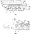
Fig. 1 schematically shows a diagram of an air outlet of an air conditioner in the invention; -
Fig. 2 schematically shows a local diagram of an air-guiding device in the invention; and -
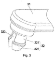
Fig. 3 schematically shows a diagram of a protrusion part of an air-guiding device in the invention. - Drawing marks: 10, mounting plate; 20, blade; 30, connecting rod; 31, body; 32, protrusion; 33, handle; 40, guiding plate; 41, limiting opening; 42, first assistant opening; 43, second assistant opening; 321, rod body; 322, flange; 323, groove; and 100, conditioner body.
- The embodiments of the invention are described below in detail with reference to the drawings. However, the invention can be implemented in multiple different modes limited and covered by claims.
- According to one aspect of the invention, an air-guiding device is provided. As shown in
Fig. 1 to Fig. 3 , the air-guiding device comprises: amounting plate 10; a plurality ofblades 20, provided on themounting plate 10; a connectingrod 30, comprising abody 31 and a guidingprotrusion 32 provided on thebody 31, thebody 31 being connected with theblades 20; and a guidingplate 40, alimiting opening 41 being provided on the guidingplate 40, a part of the guidingprotrusion 32 being provided in thelimiting opening 41 and located by thelimiting opening 41. The guidingprotrusion 32 can slide in thelimiting opening 41 along an extending direction of thelimiting opening 41 under an action of an external force, and an edge, in contact with the guidingprotrusion 32, of thelimiting opening 41 has a smoothly deformed curved surface. - The
blades 20 of the air-guiding device in the invention are connected by the connectingrod 30, theblades 20 rotate along with a movement of the connectingrod 30, and therefore a person can adjust an air direction by moving the connectingrod 30. The guidingprotrusion 32 on the connectingrod 30 is located by thelimiting opening 41, and the edge, in contact with the guidingprotrusion 32, of thelimiting opening 41 has the smoothly deformed curved surface, so that the size and the direction of a force exerted on the guidingprotrusion 32 during movement in thelimiting opening 41 cannot be suddenly changed, and the guidingprotrusion 32 can steadily move in thelimiting opening 41 under the action of the external force, thereby enabling the guidingprotrusion 32 and thelimiting opening 41 to smoothly rub against each other when the connectingrod 30 is moved. The resistance is lower than the movement resistance of a chuck in a saw-toothed locating structure, and the guidingprotrusion 32 is easier to slide. In addition, since the guidingprotrusion 32 will not suddenly hit thelimiting opening 41 in a sliding process, the sliding noise is lower. - Preferably, the
limiting opening 41 is arc-shaped. The guidingprotrusion 32 can smoothly slide in the arc-shapedlimiting opening 41, and the guidingprotrusion 32 is self-locked in the arc-shaped limitingopening 41 by means of a friction force. - Alternatively, the
limiting opening 41 is wavy. The wavy limiting opening 41 is not saw-toothed in the prior art. A stress direction of the guidingprotrusion 32 during movement in the wavy limiting opening is uniformly changed, and sudden change of the stress direction caused by movement in a saw-toothed bayonet cannot be caused. Thus, the guidingprotrusion 32 can steadily move in thelimiting opening 41 under the action of the external force, and can be more stably fixed to a valley position of thelimiting opening 41. Compared with the saw-toothed bayonet, thewavy limiting opening 41 has the advantages that the guidingprotrusion 32 can more steadily slide in thewavy limiting opening 41, the friction force is relatively small, and the generated noise is relatively weak. - Preferably, the guiding
protrusion 32 can be self-locked at a random position in thelimiting opening 41. Compared with the prior art in which the chuck may be only fixed to a valley part in the saw-toothed bayonet, the invention has the advantages that the guidingprotrusion 32 can be self-locked at the random position in thelimiting opening 41, thereby providing more diversified optional air supply directions. - Preferably, a maximum outer diameter of the guiding
protrusion 32 is 0.2-0.8mm greater than a width of the limitingopening 41. Thus, the guidingprotrusion 32 is enabled to be tightly clamped in the limitingopening 41 usually, so as to be self-locked without random movement, thereby guaranteeing a direction stability of theblades 20. A difference between the maximum outer diameter of the guidingprotrusion 32 and the width of the limitingopening 41 is decided according to a material of the guidingplate 40. If the guidingplate 40 is made of a material which is easily deformed, the difference between the maximum outer diameter of the guidingprotrusion 32 and the width of the limitingopening 41 can be relatively large. If the guidingplate 40 is made of a material which is not easily deformed, the difference is relatively small. - Preferably, an interference of about 0.3mm exists between the guiding
protrusion 32 and the limitingopening 41 in an actual movement process so as to enable the guidingprotrusion 32 to be self-locked. Meanwhile, an interference value cannot be over-large. Otherwise, the resistance is over-high, which does not facilitate sliding of the guidingprotrusion 32. - Preferably, as shown in
Fig. 1 and Fig. 2 , the guidingprotrusion 32 is provided at one end of thebody 31. The guidingprotrusion 32 and the guidingplate 40 can be provided outside the air outlet, and therefore the air outlet can be more simplified. - Preferably, the connecting
rod 30 further comprises ahandle 33. Thehandle 33 is provided on thebody 31, and extends towards a direction away from theblades 20. - According to the invention, the guiding
plate 40 further comprises a first assistant opening 42 configured to assist in expanding the limitingopening 41. Preferably, the guidingplate 40 further comprises a second assistant opening 43 configured to assist in expanding the limitingopening 41, thefirst assistant opening 42 being provided on one side of
the limitingopening 41, and the second assistant opening 43 being provided on the other side of the limitingopening 41. Since the diameter of the guidingprotrusion 32 is greater than the width of the limitingopening 41, the guidingprotrusion 32 or the limitingopening 41 will be deformed when the guidingprotrusion 32 moves in the limitingopening 41. In order to make the guidingprotrusion 32 move in the limitingopening 41 more conveniently, an assistant opening is provided on the guidingplate 40 in the invention so as to assist in deforming and expanding the limitingopening 41. - Preferably, as shown in
Fig. 2 , the limitingopening 41 is arc-shaped, and thefirst assistant opening 42 and the second assistant opening 43 are identical to the limitingopening 41 in curvature. If the limitingopening 41 is wavy, thefirst assistant opening 42 and the second assistant opening 43 may be arc-shaped, or may be wavy in correspondence to the limitingopening 41. - Preferably, the air-guiding device comprises a plurality of second
assistant openings 43, thefirst assistant opening 42 is corresponding to the middle of the limitingopening 41, and thesecond assistant openings 43 are corresponding to two ends of the limitingopening 41. Since the guidingprotrusion 32 moves in the limitingopening 41 along different stress directions, when the guidingprotrusion 32 moves to the middle of the limitingopening 41, the limitingopening 41 is deformed towards a centre direction of an arc, so that thefirst assistant opening 42 is provided on a side, close to the centre, of the limitingopening 41. When the guidingprotrusion 32 moves to the two ends of the limitingopening 41, the limitingopening 41 needs to be deformed towards a side away from the centre, so that thesecond assistant openings 43 are provided on the side, away from the centre, of the limitingopening 41. If an assistant opening is provided on only one side, the resistance of movement of the guidingprotrusion 32 in the middle or at the end of the limitingopening 41 is high, and the guidingprotrusion 32 is unlikely to poke. If the assistant openings completely corresponding to the limitingopening 41 are provided on two sides simultaneously, the resistance of movement of the guidingprotrusion 32 in the middle or at the end of the limitingopening 41 is over-low, and the guidingprotrusion 32 is difficult to self-lock. However, the effect of assisting the limitingopening 41 in deformation can be achieved by providing the assistant opening on only one side of the limitingopening 41 or providing the complete assistant openings on the two sides of the limiting opening. The design of the assistant openings shown inFig. 2 is preferred. - Preferably, two ends of the
first assistant opening 42 and each of thesecond assistant openings 43 are partially overlapped in the extending direction of the limitingopening 41. A mutual overlapping degree of thefirst assistant opening 42 and at least one of thesecond assistant openings 43 is 8 to 15 DEG. If both a centre of thefirst assistant opening 42 and a centre of the second assistant opening 43 are concentric, the mutual overlapping degree is a central angle corresponding to a overlap of thefirst assistant opening 42 and thesecond assistant opening 43. If both the centre of thefirst assistant opening 42 and the centre of the second assistant opening 43 are not concentric, the mutual overlapping degree is a central angle of the first assistant opening 42 corresponding to the overlap or a central angle of the second assistant opening 43 corresponding to the overlap. An overlapped area is intended to more facilitate the deformation of the limitingopening 41 when the guidingprotrusion 32 moves to a corresponding position. - Preferably, the centre radius of the limiting
opening 41 is 23mm to 27mm. - Preferably, as shown in
Fig. 3 , the guidingprotrusion 32 comprises arod body 321 and aflange 322 located at an end of therod body 321, a maximum outer diameter of theflange 322 is greater than a diameter of therod body 321, and theflange 322 penetrates through the limitingopening 41. Theflange 322 can be configured to prevent the guidingprotrusion 32 from disengaging from the limitingopening 41 so as to guarantee that theblades 20 will not be out of control. - Preferably, the diameter of an end, away from the
rod body 321, of theflange 322 is smaller than the width of the limitingopening 41. One end of theflange 322 is conical, so that the limitingopening 41 can be more conveniently widened, thereby sleeving theflange 322 by the limitingopening 41. - Preferably, a
groove 323 is provided on theflange 322 along an axial direction of the guidingprotrusion 32. Preferably, thegroove 323 extends to the middle of therod body 321. When the guidingprotrusion 32 is mounted into the limitingopening 41, if it is expected to inwardly squeeze theflange 322 to push the flange through the limitingopening 41, the flange can be assisted in deformation by providing thegroove 323. After penetrating through the limitingopening 41, theflange 322 springs back. During disassembly, theflange 322 is squeezed inwardly, and then is withdrawn from the limitingopening 41. In addition, thegroove 323 can also assist therod body 321 in deformation in order to move in the limitingopening 41. - According to another aspect of the invention, an air conditioner is also provided. As shown in
Fig. 1 , the air conditioner comprises aconditioner body 100. An air outlet is provided at theconditioner body 100. The air conditioner further comprises an air-guiding device according to claims. The air-guiding device is provided at the air outlet, and a mountingplate 10 of the air-guiding device is connected with theconditioner body 100. - By means of the air conditioner with the air-guiding device in the invention, the air-guiding device is easy to adjust, low in resistance and low in noise, and the service life is longer than that of the saw-toothed bayonet in the prior art. In addition, as shown in
Fig. 1 , a guidingprotrusion 32 and a guidingplate 40 are provided outside the air outlet of the air conditioner, air output from the air outlet cannot be affected, and the effect of making the air outlet tidy and attractive can be achieved. - Preferably, the mounting
plate 10 of the air-guiding device and the conditioner body are integrally formed. - Preferably, the guiding
plate 40 and the conditioner body are integrally formed.
Claims (11)
- An air-guiding device, comprising:a mounting plate (10);a plurality of blades (20), provided on the mounting plate (10);a connecting rod (30), comprising a body (31) and a guiding protrusion (32) provided on the body (31), the body (31) being connected with the blades (20); anda guiding plate (40), a limiting opening (41) being provided on the guiding plate (40), a part of the guiding protrusion (32) being provided in the limiting opening (41) and located by the limiting opening (41), the guiding protrusion (32) being capable of sliding in the limiting opening (41) along an extending direction of the limiting opening (41) under an action of an external force, and an edge, in contact with the guiding protrusion (32), of the limiting opening (41) having a smoothly deformed curved surface,characterized in that
the guiding plate (40) further comprises a first assistant opening (42) configured to assist in expanding the limiting opening (41). - The air-guiding device according to claim 1, wherein a maximum outer diameter of the guiding protrusion (32) is 0.2-0.8mm greater than a width of the limiting opening (41).
- The air-guiding device according to claim 1, wherein the guiding plate (40) further comprises a second assistant opening (43) configured to assist in expanding the limiting opening (41), the first assistant opening (42) being provided on one side of the limiting opening (41), and the second assistant opening (43) being provided on the other side of the limiting opening (41).
- The air-guiding device according to claim 3, wherein the limiting opening (41) is arc-shaped, and the first assistant opening (42) and the second assistant opening (43) are identical to the limiting opening (41) in curvature.
- The air-guiding device according to claim 3, wherein the air-guiding device comprises a plurality of second assistant openings (43), the first assistant opening (42) is corresponding to the middle of the limiting opening (41), and the second assistant openings (43) are corresponding to two ends of the limiting opening (41).
- The air-guiding device according to claim 5, wherein two ends of the first assistant opening (42) and each of the second assistant openings (43) are partially overlapped in the extending direction of the limiting opening (41), and a mutual overlapping degree of the first assistant opening (42) and at least one of the second assistant openings (43) is 8 to 15 DEG.
- The air-guiding device according to claim 1, wherein the guiding protrusion (32) comprises a rod body (321) and a flange (322) located at an end of the rod body (321), the maximum outer diameter of the flange (322) is greater than a diameter of the rod body (321), and the flange (322) penetrates through the limiting opening (41).
- The air-guiding device according to claim 7, wherein the diameter of an end, away from the rod body (321), of the flange (322) is smaller than a width of the limiting opening (41).
- The air-guiding device according to claim 7, wherein a groove (323) is provided on the flange (322) along an axial direction of the guiding protrusion (32).
- The air-guiding device according to claim 9, wherein the groove (323) extends to an end, away from the flange (322), of the rod body (321).
- An air conditioner, comprising a conditioner body (100), an air outlet being provided at the conditioner body (100), wherein the air conditioner further comprising an air-guiding device according to any one of claims 1 to 10, the air-guiding device being provided at the air outlet, and a mounting plate (10) of the air-guiding device being connected with the conditioner body (100).
Applications Claiming Priority (2)
| Application Number | Priority Date | Filing Date | Title |
|---|---|---|---|
| CN201310520371.8A CN104566901A (en) | 2013-10-28 | 2013-10-28 | Air guide device and air conditioner |
| PCT/CN2014/081610 WO2015062305A1 (en) | 2013-10-28 | 2014-07-03 | Air-guiding apparatus and air conditioner |
Publications (3)
| Publication Number | Publication Date |
|---|---|
| EP3064855A1 EP3064855A1 (en) | 2016-09-07 |
| EP3064855A4 EP3064855A4 (en) | 2017-07-05 |
| EP3064855B1 true EP3064855B1 (en) | 2019-08-28 |
Family
ID=53003268
Family Applications (1)
| Application Number | Title | Priority Date | Filing Date |
|---|---|---|---|
| EP14857504.6A Active EP3064855B1 (en) | 2013-10-28 | 2014-07-03 | Air-guiding device and air conditioner |
Country Status (4)
| Country | Link |
|---|---|
| EP (1) | EP3064855B1 (en) |
| CN (1) | CN104566901A (en) |
| ES (1) | ES2759079T3 (en) |
| WO (1) | WO2015062305A1 (en) |
Families Citing this family (4)
| Publication number | Priority date | Publication date | Assignee | Title |
|---|---|---|---|---|
| CN106871411B (en) * | 2017-04-10 | 2022-12-20 | 珠海格力电器股份有限公司 | Sweep wind subassembly and air conditioner |
| CN107328073A (en) * | 2017-06-27 | 2017-11-07 | 奥克斯空调股份有限公司 | A kind of fan blade assembling structure of air conditioner |
| CN107621019A (en) * | 2017-10-12 | 2018-01-23 | 广州百兴网络科技有限公司 | A kind of energy saving and environment friendly air cleaning unit and purification method |
| CN111895507A (en) * | 2020-07-29 | 2020-11-06 | Tcl空调器(中山)有限公司 | Air ducting and air conditioner indoor unit |
Family Cites Families (17)
| Publication number | Priority date | Publication date | Assignee | Title |
|---|---|---|---|---|
| US2761371A (en) * | 1953-03-16 | 1956-09-04 | Us Register Company | Removable lever operated register |
| US4777870A (en) * | 1987-11-02 | 1988-10-18 | Carrier Corporation | Adjustable air sweep mechanism for a room air conditioner |
| US4876951A (en) * | 1987-12-09 | 1989-10-31 | Hart & Cooley, Inc. | Air register handle arrangement |
| TW331584B (en) * | 1996-05-20 | 1998-05-11 | Fujitsu General Ltd | The air conditioner |
| DE19728305C2 (en) * | 1997-07-03 | 2000-11-30 | Trw Adv Plastic Tech Gmbh & Co | Louver system for ventilation devices for regulating the air flow, in particular for ventilation in motor vehicles |
| JP2005029084A (en) * | 2003-07-10 | 2005-02-03 | Howa Kasei Kk | Wind direction adjustment device |
| CN2655098Y (en) * | 2003-11-16 | 2004-11-10 | 罗启康 | Electrocontrolled air outlet for central air conditioner |
| KR100596254B1 (en) * | 2004-06-17 | 2006-07-03 | 엘지전자 주식회사 | Indoor unit of separate air conditioner |
| WO2008010384A1 (en) * | 2006-07-19 | 2008-01-24 | Mitsubishi Electric Corporation | Air conditioner |
| CN101852480B (en) * | 2009-04-01 | 2012-09-05 | 珠海格力电器股份有限公司 | Air conditioner |
| JP5267373B2 (en) * | 2009-08-05 | 2013-08-21 | パナソニック株式会社 | Air conditioner wind direction change device |
| JP4883170B2 (en) * | 2009-10-05 | 2012-02-22 | ダイキン工業株式会社 | Air conditioner indoor unit |
| CN201748601U (en) * | 2010-07-12 | 2011-02-16 | 珠海格力电器股份有限公司 | Air guide device |
| JP5404713B2 (en) * | 2011-08-11 | 2014-02-05 | 三菱電機株式会社 | Left and right wind direction adjusting device and air conditioner indoor unit equipped with the same |
| CN202267188U (en) * | 2011-08-17 | 2012-06-06 | 格力电器(武汉)有限公司 | Wind sweeping structure for wall hanging type air conditioner |
| CN202303808U (en) * | 2011-10-10 | 2012-07-04 | 广州华凌空调设备有限公司 | Integrated air guide mechanism for air conditioner |
| CN203518162U (en) * | 2013-10-28 | 2014-04-02 | 珠海格力电器股份有限公司 | Air guide device and air conditioner |
-
2013
- 2013-10-28 CN CN201310520371.8A patent/CN104566901A/en active Pending
-
2014
- 2014-07-03 EP EP14857504.6A patent/EP3064855B1/en active Active
- 2014-07-03 ES ES14857504T patent/ES2759079T3/en active Active
- 2014-07-03 WO PCT/CN2014/081610 patent/WO2015062305A1/en not_active Ceased
Non-Patent Citations (1)
| Title |
|---|
| None * |
Also Published As
| Publication number | Publication date |
|---|---|
| WO2015062305A1 (en) | 2015-05-07 |
| EP3064855A4 (en) | 2017-07-05 |
| ES2759079T3 (en) | 2020-05-07 |
| CN104566901A (en) | 2015-04-29 |
| EP3064855A1 (en) | 2016-09-07 |
Similar Documents
| Publication | Publication Date | Title |
|---|---|---|
| US20130078900A1 (en) | Air Outlet Directional Flow Controller with Integrated Shut-Off Door | |
| CN216592184U (en) | Air deflector assembly and air conditioner with same | |
| EP3134650B1 (en) | Centrifugal fan assembly and methods of assembling the same | |
| CN207315701U (en) | Axial flow blower and there are its household electrical appliance | |
| EP3064855A1 (en) | Air-guiding device and air conditioner | |
| JP2015509567A5 (en) | Axial fan and method of manufacturing axial fan | |
| CN108105982B (en) | Air guide plate assembly and wall-mounted indoor unit | |
| CN205078498U (en) | Blade and ceiling fan for ceiling fan | |
| CN108443198A (en) | Driving mechanism, head section mechanism and fan | |
| JP6066714B2 (en) | register | |
| CN108981125B (en) | Louver mechanism and air outlet device with same | |
| CN203642434U (en) | Air conditioner and air deflecting device thereof | |
| CN204388318U (en) | For air-conditioner wind guiding component and there is its air-conditioner | |
| CN211032113U (en) | Air outlet blade resistance built-in control structure | |
| EP3109079B1 (en) | Air discharge device | |
| JP2017500463A5 (en) | ||
| US20170361682A1 (en) | Vane adjustment device and a vehicle air register assembly | |
| CN108443199A (en) | Tilting component, head section mechanism and household electrical appliance | |
| EP2752322A1 (en) | Air ejection device | |
| CN108412795A (en) | Head section mechanism and household electrical appliance | |
| CN110500756B (en) | Air outlet assembly, control method and air conditioner | |
| CN108412796A (en) | Head section mechanism and household electrical appliance | |
| JP6343177B2 (en) | Wiper arm | |
| CN204126921U (en) | Blower | |
| CN108443200B (en) | Pitching assembly, machine head mechanism and household appliance |
Legal Events
| Date | Code | Title | Description |
|---|---|---|---|
| PUAI | Public reference made under article 153(3) epc to a published international application that has entered the european phase |
Free format text: ORIGINAL CODE: 0009012 |
|
| 17P | Request for examination filed |
Effective date: 20160527 |
|
| AK | Designated contracting states |
Kind code of ref document: A1 Designated state(s): AL AT BE BG CH CY CZ DE DK EE ES FI FR GB GR HR HU IE IS IT LI LT LU LV MC MK MT NL NO PL PT RO RS SE SI SK SM TR |
|
| AX | Request for extension of the european patent |
Extension state: BA ME |
|
| DAX | Request for extension of the european patent (deleted) | ||
| A4 | Supplementary search report drawn up and despatched |
Effective date: 20170602 |
|
| RIC1 | Information provided on ipc code assigned before grant |
Ipc: F24F 13/15 20060101AFI20170529BHEP Ipc: F24F 1/00 20110101ALI20170529BHEP |
|
| GRAP | Despatch of communication of intention to grant a patent |
Free format text: ORIGINAL CODE: EPIDOSNIGR1 |
|
| STAA | Information on the status of an ep patent application or granted ep patent |
Free format text: STATUS: GRANT OF PATENT IS INTENDED |
|
| INTG | Intention to grant announced |
Effective date: 20190318 |
|
| GRAS | Grant fee paid |
Free format text: ORIGINAL CODE: EPIDOSNIGR3 |
|
| GRAA | (expected) grant |
Free format text: ORIGINAL CODE: 0009210 |
|
| STAA | Information on the status of an ep patent application or granted ep patent |
Free format text: STATUS: THE PATENT HAS BEEN GRANTED |
|
| AK | Designated contracting states |
Kind code of ref document: B1 Designated state(s): AL AT BE BG CH CY CZ DE DK EE ES FI FR GB GR HR HU IE IS IT LI LT LU LV MC MK MT NL NO PL PT RO RS SE SI SK SM TR |
|
| REG | Reference to a national code |
Ref country code: GB Ref legal event code: FG4D |
|
| REG | Reference to a national code |
Ref country code: CH Ref legal event code: EP |
|
| REG | Reference to a national code |
Ref country code: DE Ref legal event code: R096 Ref document number: 602014052716 Country of ref document: DE |
|
| REG | Reference to a national code |
Ref country code: AT Ref legal event code: REF Ref document number: 1172895 Country of ref document: AT Kind code of ref document: T Effective date: 20190915 |
|
| REG | Reference to a national code |
Ref country code: IE Ref legal event code: FG4D |
|
| REG | Reference to a national code |
Ref country code: NL Ref legal event code: MP Effective date: 20190828 |
|
| REG | Reference to a national code |
Ref country code: LT Ref legal event code: MG4D |
|
| PG25 | Lapsed in a contracting state [announced via postgrant information from national office to epo] |
Ref country code: HR Free format text: LAPSE BECAUSE OF FAILURE TO SUBMIT A TRANSLATION OF THE DESCRIPTION OR TO PAY THE FEE WITHIN THE PRESCRIBED TIME-LIMIT Effective date: 20190828 Ref country code: LT Free format text: LAPSE BECAUSE OF FAILURE TO SUBMIT A TRANSLATION OF THE DESCRIPTION OR TO PAY THE FEE WITHIN THE PRESCRIBED TIME-LIMIT Effective date: 20190828 Ref country code: PT Free format text: LAPSE BECAUSE OF FAILURE TO SUBMIT A TRANSLATION OF THE DESCRIPTION OR TO PAY THE FEE WITHIN THE PRESCRIBED TIME-LIMIT Effective date: 20191230 Ref country code: SE Free format text: LAPSE BECAUSE OF FAILURE TO SUBMIT A TRANSLATION OF THE DESCRIPTION OR TO PAY THE FEE WITHIN THE PRESCRIBED TIME-LIMIT Effective date: 20190828 Ref country code: BG Free format text: LAPSE BECAUSE OF FAILURE TO SUBMIT A TRANSLATION OF THE DESCRIPTION OR TO PAY THE FEE WITHIN THE PRESCRIBED TIME-LIMIT Effective date: 20191128 Ref country code: NL Free format text: LAPSE BECAUSE OF FAILURE TO SUBMIT A TRANSLATION OF THE DESCRIPTION OR TO PAY THE FEE WITHIN THE PRESCRIBED TIME-LIMIT Effective date: 20190828 Ref country code: FI Free format text: LAPSE BECAUSE OF FAILURE TO SUBMIT A TRANSLATION OF THE DESCRIPTION OR TO PAY THE FEE WITHIN THE PRESCRIBED TIME-LIMIT Effective date: 20190828 Ref country code: NO Free format text: LAPSE BECAUSE OF FAILURE TO SUBMIT A TRANSLATION OF THE DESCRIPTION OR TO PAY THE FEE WITHIN THE PRESCRIBED TIME-LIMIT Effective date: 20191128 |
|
| PG25 | Lapsed in a contracting state [announced via postgrant information from national office to epo] |
Ref country code: RS Free format text: LAPSE BECAUSE OF FAILURE TO SUBMIT A TRANSLATION OF THE DESCRIPTION OR TO PAY THE FEE WITHIN THE PRESCRIBED TIME-LIMIT Effective date: 20190828 Ref country code: IS Free format text: LAPSE BECAUSE OF FAILURE TO SUBMIT A TRANSLATION OF THE DESCRIPTION OR TO PAY THE FEE WITHIN THE PRESCRIBED TIME-LIMIT Effective date: 20191228 Ref country code: LV Free format text: LAPSE BECAUSE OF FAILURE TO SUBMIT A TRANSLATION OF THE DESCRIPTION OR TO PAY THE FEE WITHIN THE PRESCRIBED TIME-LIMIT Effective date: 20190828 Ref country code: AL Free format text: LAPSE BECAUSE OF FAILURE TO SUBMIT A TRANSLATION OF THE DESCRIPTION OR TO PAY THE FEE WITHIN THE PRESCRIBED TIME-LIMIT Effective date: 20190828 Ref country code: GR Free format text: LAPSE BECAUSE OF FAILURE TO SUBMIT A TRANSLATION OF THE DESCRIPTION OR TO PAY THE FEE WITHIN THE PRESCRIBED TIME-LIMIT Effective date: 20191129 |
|
| REG | Reference to a national code |
Ref country code: AT Ref legal event code: MK05 Ref document number: 1172895 Country of ref document: AT Kind code of ref document: T Effective date: 20190828 |
|
| PG25 | Lapsed in a contracting state [announced via postgrant information from national office to epo] |
Ref country code: TR Free format text: LAPSE BECAUSE OF FAILURE TO SUBMIT A TRANSLATION OF THE DESCRIPTION OR TO PAY THE FEE WITHIN THE PRESCRIBED TIME-LIMIT Effective date: 20190828 |
|
| PG25 | Lapsed in a contracting state [announced via postgrant information from national office to epo] |
Ref country code: AT Free format text: LAPSE BECAUSE OF FAILURE TO SUBMIT A TRANSLATION OF THE DESCRIPTION OR TO PAY THE FEE WITHIN THE PRESCRIBED TIME-LIMIT Effective date: 20190828 Ref country code: DK Free format text: LAPSE BECAUSE OF FAILURE TO SUBMIT A TRANSLATION OF THE DESCRIPTION OR TO PAY THE FEE WITHIN THE PRESCRIBED TIME-LIMIT Effective date: 20190828 Ref country code: PL Free format text: LAPSE BECAUSE OF FAILURE TO SUBMIT A TRANSLATION OF THE DESCRIPTION OR TO PAY THE FEE WITHIN THE PRESCRIBED TIME-LIMIT Effective date: 20190828 Ref country code: IT Free format text: LAPSE BECAUSE OF FAILURE TO SUBMIT A TRANSLATION OF THE DESCRIPTION OR TO PAY THE FEE WITHIN THE PRESCRIBED TIME-LIMIT Effective date: 20190828 Ref country code: EE Free format text: LAPSE BECAUSE OF FAILURE TO SUBMIT A TRANSLATION OF THE DESCRIPTION OR TO PAY THE FEE WITHIN THE PRESCRIBED TIME-LIMIT Effective date: 20190828 Ref country code: RO Free format text: LAPSE BECAUSE OF FAILURE TO SUBMIT A TRANSLATION OF THE DESCRIPTION OR TO PAY THE FEE WITHIN THE PRESCRIBED TIME-LIMIT Effective date: 20190828 |
|
| REG | Reference to a national code |
Ref country code: ES Ref legal event code: FG2A Ref document number: 2759079 Country of ref document: ES Kind code of ref document: T3 Effective date: 20200507 |
|
| PG25 | Lapsed in a contracting state [announced via postgrant information from national office to epo] |
Ref country code: SM Free format text: LAPSE BECAUSE OF FAILURE TO SUBMIT A TRANSLATION OF THE DESCRIPTION OR TO PAY THE FEE WITHIN THE PRESCRIBED TIME-LIMIT Effective date: 20190828 Ref country code: CZ Free format text: LAPSE BECAUSE OF FAILURE TO SUBMIT A TRANSLATION OF THE DESCRIPTION OR TO PAY THE FEE WITHIN THE PRESCRIBED TIME-LIMIT Effective date: 20190828 Ref country code: SK Free format text: LAPSE BECAUSE OF FAILURE TO SUBMIT A TRANSLATION OF THE DESCRIPTION OR TO PAY THE FEE WITHIN THE PRESCRIBED TIME-LIMIT Effective date: 20190828 Ref country code: IS Free format text: LAPSE BECAUSE OF FAILURE TO SUBMIT A TRANSLATION OF THE DESCRIPTION OR TO PAY THE FEE WITHIN THE PRESCRIBED TIME-LIMIT Effective date: 20200224 |
|
| REG | Reference to a national code |
Ref country code: DE Ref legal event code: R097 Ref document number: 602014052716 Country of ref document: DE |
|
| PLBE | No opposition filed within time limit |
Free format text: ORIGINAL CODE: 0009261 |
|
| STAA | Information on the status of an ep patent application or granted ep patent |
Free format text: STATUS: NO OPPOSITION FILED WITHIN TIME LIMIT |
|
| PG2D | Information on lapse in contracting state deleted |
Ref country code: IS |
|
| 26N | No opposition filed |
Effective date: 20200603 |
|
| PG25 | Lapsed in a contracting state [announced via postgrant information from national office to epo] |
Ref country code: SI Free format text: LAPSE BECAUSE OF FAILURE TO SUBMIT A TRANSLATION OF THE DESCRIPTION OR TO PAY THE FEE WITHIN THE PRESCRIBED TIME-LIMIT Effective date: 20190828 |
|
| REG | Reference to a national code |
Ref country code: DE Ref legal event code: R119 Ref document number: 602014052716 Country of ref document: DE |
|
| PG25 | Lapsed in a contracting state [announced via postgrant information from national office to epo] |
Ref country code: MC Free format text: LAPSE BECAUSE OF FAILURE TO SUBMIT A TRANSLATION OF THE DESCRIPTION OR TO PAY THE FEE WITHIN THE PRESCRIBED TIME-LIMIT Effective date: 20190828 |
|
| REG | Reference to a national code |
Ref country code: CH Ref legal event code: PL |
|
| GBPC | Gb: european patent ceased through non-payment of renewal fee |
Effective date: 20200703 |
|
| REG | Reference to a national code |
Ref country code: BE Ref legal event code: MM Effective date: 20200731 |
|
| PG25 | Lapsed in a contracting state [announced via postgrant information from national office to epo] |
Ref country code: LU Free format text: LAPSE BECAUSE OF NON-PAYMENT OF DUE FEES Effective date: 20200703 Ref country code: LI Free format text: LAPSE BECAUSE OF NON-PAYMENT OF DUE FEES Effective date: 20200731 Ref country code: FR Free format text: LAPSE BECAUSE OF NON-PAYMENT OF DUE FEES Effective date: 20200731 Ref country code: CH Free format text: LAPSE BECAUSE OF NON-PAYMENT OF DUE FEES Effective date: 20200731 Ref country code: IE Free format text: LAPSE BECAUSE OF NON-PAYMENT OF DUE FEES Effective date: 20200703 Ref country code: GB Free format text: LAPSE BECAUSE OF NON-PAYMENT OF DUE FEES Effective date: 20200703 |
|
| PG25 | Lapsed in a contracting state [announced via postgrant information from national office to epo] |
Ref country code: DE Free format text: LAPSE BECAUSE OF NON-PAYMENT OF DUE FEES Effective date: 20210202 Ref country code: BE Free format text: LAPSE BECAUSE OF NON-PAYMENT OF DUE FEES Effective date: 20200731 |
|
| PG25 | Lapsed in a contracting state [announced via postgrant information from national office to epo] |
Ref country code: MT Free format text: LAPSE BECAUSE OF FAILURE TO SUBMIT A TRANSLATION OF THE DESCRIPTION OR TO PAY THE FEE WITHIN THE PRESCRIBED TIME-LIMIT Effective date: 20190828 Ref country code: CY Free format text: LAPSE BECAUSE OF FAILURE TO SUBMIT A TRANSLATION OF THE DESCRIPTION OR TO PAY THE FEE WITHIN THE PRESCRIBED TIME-LIMIT Effective date: 20190828 |
|
| PG25 | Lapsed in a contracting state [announced via postgrant information from national office to epo] |
Ref country code: MK Free format text: LAPSE BECAUSE OF FAILURE TO SUBMIT A TRANSLATION OF THE DESCRIPTION OR TO PAY THE FEE WITHIN THE PRESCRIBED TIME-LIMIT Effective date: 20190828 |
|
| P01 | Opt-out of the competence of the unified patent court (upc) registered |
Effective date: 20230530 |
|
| PGFP | Annual fee paid to national office [announced via postgrant information from national office to epo] |
Ref country code: ES Payment date: 20250819 Year of fee payment: 12 |