EP3064736B1 - Rotary dust screen - Google Patents
Rotary dust screen Download PDFInfo
- Publication number
- EP3064736B1 EP3064736B1 EP16158588.0A EP16158588A EP3064736B1 EP 3064736 B1 EP3064736 B1 EP 3064736B1 EP 16158588 A EP16158588 A EP 16158588A EP 3064736 B1 EP3064736 B1 EP 3064736B1
- Authority
- EP
- European Patent Office
- Prior art keywords
- dust screen
- rotary
- cooling unit
- rotary dust
- frame
- Prior art date
- Legal status (The legal status is an assumption and is not a legal conclusion. Google has not performed a legal analysis and makes no representation as to the accuracy of the status listed.)
- Active
Links
Images

Classifications
-
- B—PERFORMING OPERATIONS; TRANSPORTING
- B01—PHYSICAL OR CHEMICAL PROCESSES OR APPARATUS IN GENERAL
- B01D—SEPARATION
- B01D46/00—Filters or filtering processes specially modified for separating dispersed particles from gases or vapours
- B01D46/0052—Filters or filtering processes specially modified for separating dispersed particles from gases or vapours with filtering elements moving during filtering operation
- B01D46/0056—Filters or filtering processes specially modified for separating dispersed particles from gases or vapours with filtering elements moving during filtering operation with rotational movement
-
- A—HUMAN NECESSITIES
- A01—AGRICULTURE; FORESTRY; ANIMAL HUSBANDRY; HUNTING; TRAPPING; FISHING
- A01B—SOIL WORKING IN AGRICULTURE OR FORESTRY; PARTS, DETAILS, OR ACCESSORIES OF AGRICULTURAL MACHINES OR IMPLEMENTS, IN GENERAL
- A01B76/00—Parts, details or accessories of agricultural machines or implements, not provided for in groups A01B51/00 - A01B75/00
-
- B—PERFORMING OPERATIONS; TRANSPORTING
- B01—PHYSICAL OR CHEMICAL PROCESSES OR APPARATUS IN GENERAL
- B01D—SEPARATION
- B01D46/00—Filters or filtering processes specially modified for separating dispersed particles from gases or vapours
- B01D46/10—Particle separators, e.g. dust precipitators, using filter plates, sheets or pads having plane surfaces
-
- B—PERFORMING OPERATIONS; TRANSPORTING
- B01—PHYSICAL OR CHEMICAL PROCESSES OR APPARATUS IN GENERAL
- B01D—SEPARATION
- B01D46/00—Filters or filtering processes specially modified for separating dispersed particles from gases or vapours
- B01D46/66—Regeneration of the filtering material or filter elements inside the filter
- B01D46/68—Regeneration of the filtering material or filter elements inside the filter by means acting on the cake side involving movement with regard to the filter elements
- B01D46/682—Regeneration of the filtering material or filter elements inside the filter by means acting on the cake side involving movement with regard to the filter elements by nozzles
-
- F—MECHANICAL ENGINEERING; LIGHTING; HEATING; WEAPONS; BLASTING
- F01—MACHINES OR ENGINES IN GENERAL; ENGINE PLANTS IN GENERAL; STEAM ENGINES
- F01P—COOLING OF MACHINES OR ENGINES IN GENERAL; COOLING OF INTERNAL-COMBUSTION ENGINES
- F01P1/00—Air cooling
- F01P1/06—Arrangements for cooling other engine or machine parts
-
- F—MECHANICAL ENGINEERING; LIGHTING; HEATING; WEAPONS; BLASTING
- F01—MACHINES OR ENGINES IN GENERAL; ENGINE PLANTS IN GENERAL; STEAM ENGINES
- F01P—COOLING OF MACHINES OR ENGINES IN GENERAL; COOLING OF INTERNAL-COMBUSTION ENGINES
- F01P11/00—Component parts, details, or accessories not provided for in, or of interest apart from, groups F01P1/00 - F01P9/00
- F01P11/06—Cleaning; Combating corrosion
-
- F—MECHANICAL ENGINEERING; LIGHTING; HEATING; WEAPONS; BLASTING
- F01—MACHINES OR ENGINES IN GENERAL; ENGINE PLANTS IN GENERAL; STEAM ENGINES
- F01P—COOLING OF MACHINES OR ENGINES IN GENERAL; COOLING OF INTERNAL-COMBUSTION ENGINES
- F01P11/00—Component parts, details, or accessories not provided for in, or of interest apart from, groups F01P1/00 - F01P9/00
- F01P11/12—Filtering, cooling, or silencing cooling-air
-
- A—HUMAN NECESSITIES
- A01—AGRICULTURE; FORESTRY; ANIMAL HUSBANDRY; HUNTING; TRAPPING; FISHING
- A01D—HARVESTING; MOWING
- A01D41/00—Combines, i.e. harvesters or mowers combined with threshing devices
- A01D41/12—Details of combines
- A01D41/1252—Anti-dust devices
-
- B—PERFORMING OPERATIONS; TRANSPORTING
- B01—PHYSICAL OR CHEMICAL PROCESSES OR APPARATUS IN GENERAL
- B01D—SEPARATION
- B01D2259/00—Type of treatment
- B01D2259/45—Gas separation or purification devices adapted for specific applications
- B01D2259/4566—Gas separation or purification devices adapted for specific applications for use in transportation means
-
- B—PERFORMING OPERATIONS; TRANSPORTING
- B01—PHYSICAL OR CHEMICAL PROCESSES OR APPARATUS IN GENERAL
- B01D—SEPARATION
- B01D2273/00—Operation of filters specially adapted for separating dispersed particles from gases or vapours
- B01D2273/14—Filters which are moved between two or more positions, e.g. by turning, pushing
-
- F—MECHANICAL ENGINEERING; LIGHTING; HEATING; WEAPONS; BLASTING
- F01—MACHINES OR ENGINES IN GENERAL; ENGINE PLANTS IN GENERAL; STEAM ENGINES
- F01P—COOLING OF MACHINES OR ENGINES IN GENERAL; COOLING OF INTERNAL-COMBUSTION ENGINES
- F01P11/00—Component parts, details, or accessories not provided for in, or of interest apart from, groups F01P1/00 - F01P9/00
- F01P11/06—Cleaning; Combating corrosion
- F01P2011/061—Cleaning or combating corrosion using filters
Definitions
- the present invention relates to a rotary dust screen for a cooling unit of an agricultural vehicle.
- the invention further relates to a cooling unit comprising such a rotary dust screen.
- the air intake filter as a perforated dust screen centered on an axis and preferably shaped having an axially directed perforated end and a radially directed perforated side.
- the dust screen is rotated about its axis and a cleaning device is provided which covers a typically pie-shaped segment of the dust screen, so that each time the dust screen rotates it passes through the cleaner and in theory any particles on outer surfaces of the dust screen are removed.
- US 6,248,145 describes such rotary dust screen for a cooling unit of an agricultural vehicle.
- the rotary dust screen is provided with a brush assembly whose bristles engage an inner side of the cooling unit housing. Via these brushes, entrance of contaminants into the cooling unit via an edge of the rotary dust screen is prevented.
- the rotary dust screen is driven via a belt that engages with an outer end of the rotary dust screen, which belt is driven by a rotary actuator.
- a similar arrangement is shown in GB 1 387 690 . It is an object of the present invention to provide a rotary dust screen that can be more suitably built into a cooling unit in terms of design flexibility and maintenance.
- the present invention provides a rotary dust screen for a cooling unit of an agricultural vehicle, the rotary dust screen comprising a frame having a ring shape, wherein a dust screen is mounted in the frame, and wherein the frame comprises a seal extending along the ring, and comprising a lip adapted to abut, when the rotary dust screen is mounted on the cooling unit, against a housing of the cooling unit to prevent contaminants from entering the cooling unit at an edge of the dust screen, wherein the rotary dust screen further comprises a driving belt adapted to be driven by a rotary actuator to rotate the dust screen, wherein the driving belt engages with the rotary dust screen at an outer surface of the seal.
- the rotary dust screen of the invention comprises a ring-shaped frame. All elements of the rotary dust screen are mounted directly or indirectly against this frame.
- the rotary dust screen comprises the seal with the lip for abutting against a housing of the cooling unit. This seal prevents contaminants to enter the cooling unit at an edge of the rotary dust screen.
- the driving belt that drives the rotary dust screen engages at an outer surface of that seal.
- the compact size of the ring-shaped frame has as an advantage that the rotary dust screen can be more easily built into a cooling unit, namely it takes less space. Furthermore, when more space is available in the cooling unit, the surface area of the dust screen can be made larger than conventionally since the ring-shaped frame is more compact than conventionally. Furthermore, since the driving belt is mounted at an outer side of the rotary dust screen, maintenance can be performed easily since the cooling unit must not be demounted to gain access to the driving belt or the rotary actuator driving the driving belt.
- the frame comprises an outer frame surface wherein the seal is mounted with an inner seal surface against the outer surface of the frame.
- the seal is also ring-shaped with a diameter that substantially matches the diameter of the ring-shaped frame.
- the seal is made of a resilient plastic material.
- Tests have shown that the proposed rotary dust screen wherein the driving belt engages with an outer surface of the seal operates significantly well when the seal is made of a resilient plastic material.
- the lip of the seal will, due to the resilience of the material of the seal, exert a predetermined pressure to the outer side of the housing, so that a good sealing is obtained.
- the predetermined pressure can be chosen when designing the seal with the lip.
- the friction coefficient between the driving belt and the resilient plastic material is high due to the nature of the resilient plastic material, so that the driving belt only needs to engage over a limited angle of the rotary dust screen, as will be clear from the examples given in the detailed description. This gives designers of cooling units a significant benefit and design freedom.
- the seal comprises a groove at an outer seal surface, which groove is adapted for engagement with the driving belt.
- the driving belt is a V-shaped belt to engage in the groove of the seal.
- a V-shaped belt with a predetermined width can transfer a significantly higher force than a flat belt with the same predetermined width. Therefore, providing a groove at the seal, and forming the driving belt as a V-shaped belt allows building the rotary dust screen in a more compact manner.
- the frame comprises a protrusion extending on an inner side of the ring-shaped frame, which protrusion is adapted to engage with positioning elements at the cooling unit.
- the cooling unit can for example by provided with guiding wheels that hold the rotary dust screen in position. These guiding wheels can grip the frame at the protrusion so that the position of the rotary dust screen is determined with respect to the cooling unit. Since the rotary dust screen can be positioned in the cooling unit via its frame, no central axis must be provided to the rotary dust screen, and the complete outer surface of the rotary dust screen is useable as dust filter. However a central axis may be provided for other purposes, for example for supporting the cleaning element. By not providing a central axis, the dust screen surface area can be used better.
- the dust screen is mounted at an inner segment of the frame. This in combination with the seal being mounted against an outer surface of the frame allows the frame to have a highly compact shape.
- the dust screen is formed by a metal perforated plate.
- Metal perforated plates have shown to perform well in the extremely dusty conditions wherein agricultural vehicles operate.
- the dust screen provides a cylindrical part and comprises a closing part, wherein one end of the cylindrical part is connected to the frame, while another end of the cylindrical part is closed by the closing part.
- the outer surface of the rotary dust screen is significantly increased compared to the surface area inside the ring-shaped frame, due to the cylindrical part of the dust screen.
- the cylindrical part can be made larger to compensate for the more compact shape of the frame, so that a larger dust screen surface area is obtained.
- a dust cleaning module is provided which is adapted to be mounted to the housing of the cooling unit to cover a segment of the rotary dust screen that extends between an area at the frame and an area at the center of the rotary dust screen.
- the dust cleaning module which is typically formed as a suction element, extends between an area at the frame and an area at the center of the dust screen, rotating the dust screen will have as an effect that substantially the complete dust screen passes by the dust cleaning module. In this manner, the dust screen can be kept clean by rotating the rotary dust screen.
- the present invention further relates to a cooling unit with a housing and a rotary dust screen of the invention, wherein the cooling unit comprises a rotary actuator at an outer side of the housing, which rotary actuator engages with the driving belt to rotate the dust screen.
- the cooling unit comprises multiple rotary dust screens of the invention and the multiple dust screens are driven by a single driving belt that engages with each of the outer surfaces of the seals of the multiple dust screens. Since the cooling unit can be provided with multiple rotary dust screens, which is cost efficient with the rotary dust screen of the invention, because the ring shaped frame of the rotary dust screen is compact, more design possibilities are available for designing a cooling unit. These multiple rotary dust screens can then be driven by a single driving belt which is driven by a rotary actuator at an outer side of the housing. Thereby, a compact and maintenance efficient cooling unit can be obtained.
- the present invention further relates to an agricultural vehicle with a cooling unit of the invention.
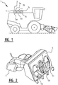
- FIG. 1 shows an agricultural vehicle 1 with a cooling unit 2.
- the shown agricultural vehicle 1 is an agricultural combine, however, it will be clear that the cooling unit 2 according to the invention is suitable for various agricultural vehicles, preferably self-propelled agricultural vehicles. Self-propelled agricultural vehicles typically require a significant cooling capacity. To achieve such cooling capacity in dusty environments, the cooling unit of the present invention can be used.
- Cooling unit 2 is adapted for drawing air from an environment of the agricultural vehicle into the cooling unit where it is typically guided over one or multiple heat exchangers and/or over other elements that require cooling.
- the present invention particularly relates to the part of the cooling unit 2, where the environmental air enters the cooling unit 2.
- the openings of the cooling unit 2 are provided with respective rotary dust screens 3.
- the rotary dust screen 3 is mounted in an opening of a housing 4 of the cooling unit 2 to cover the opening.
- the rotary dust screen 3 is provided with perforations so that air can flow through the rotary dust screen 3 into the cooling unit 2.
- the perforations have predetermined dimensions which are chosen to prevent dust particles from entering the cooling unit 2.
- the rotary dust screen 3 operates as a filter for filtering environmental air that is drawn into the cooling unit 2.
- a cleaning element 5 is provided, which is typically pie-shaped and extends over a part of the rotary dust screen 3 between an area at the edge or frame of the rotary dust screen 3 and a central area of the rotary dust screen 3.
- the cleaning element is preferably formed as a suction element that operates as a vacuum cleaner for cleaning the outer surface of the rotary dust screen.
- the cleaning element 5 is preferably mounted in a fixed position, and the dust screen 3 is rotated so that by rotation of the dust screen 3 substantially the complete rotary dust screen 3 passes by the cleaning element 5. In this manner the outer surface of the rotary dust screen is suction cleaned every time the rotary dust screen makes a full rotation, so that the rotary dust screen is prevented from getting clogged up with dust particles.
- FIG. 1 three rotary dust screens 3a, 3b, 3c are provided to cover three corresponding openings in a housing 4 of the cooling unit 2.
- Each of the rotary dust screens 3a, 3b, 3c is provided with a suction cleaning element 5a, 5b, 5c.
- the cooling unit 2 can also be designed with different numbers of rotary dust screens 3 and corresponding suction cleaners 5. Therefore, the invention is not limited to a cooling unit 2 having three rotary dust screens 3a, 3b, 3c.
- FIG. 2 shows a cooling unit 2 according to an embodiment of the invention.
- figure 2 shows the housing 4 of the cooling unit, and shows the openings in which rotary dust screens are mounted.
- the dust screens are not shown in figure 2.
- Figure 2 shows the heat exchangers 6 that are mounted inside the cooling unit 2.
- Figure 2 further shows the suction device 7 that is operationally connected to the suction elements 5a, 5b and 5c for cleaning the outer surface of the rotary dust screens.
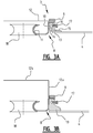
- Figure 3 shows a cross section of an edge of a rotary dust screen according to a first and a second embodiment of the present invention.
- the rotary dust screen is substantially flat, meaning that the dust screen 12 is not provided with a cylindrical part.
- the dust screen has a cylindrical part 12a and a closing part 12b, which allows to significantly increase the surface area of the dust screen. Thereby one end of the cylindrical part 12a is closed with the closing part 12b while the other end is mounted in the frame, which is described hereunder.
- the techniques for mounting the dust screen, for sealing the edges of the dust screen with respect to the housing 4 of the cooling unit and for driving the rotary dust screen are substantially the same for the first and second embodiment, as is described hereunder.
- the rotary dust screen comprises at least four main elements being a frame 8, a dust screen 12, a seal 13 and a driving belt 17. These elements of the rotary dust screen 3 cooperate with the housing 4 of the cooling unit, and optionally with positioning elements 18 that are connected to the housing 4 in order to filter the air entering the cooling unit 2. In this context it is noted that the connection between the positioning element 18 and the housing 4 is not shown in figure 3 .
- the frame 8, of which a cross section is shown in figure 3a is ring-shaped with a diameter that corresponds with the diameter of the opening in the housing 4 of the cooling unit 2.
- the ring-shaped frame 8 comprises a first part 9 for connection of the dust screen 12.
- This first part 9 is preferably formed with a U-shaped cross section that allows to clamp the dust screen 12 between the legs of the U-shape. This allows to mount the dust screen in the ring-shaped frame 8 in a convenient manner.
- the U-shape can, after positioning of the dust screen, be deformed to bring the legs of the U-shape together to thereby clamp the dust screen 12 in the frame 8. In this manner, the frame 8 is rigidly connected to the dust screen 12.
- the skilled person will understand that other ways of connecting the dust screen 12 to the ring-shaped frame 8 are also possible, for example by gluing or welding.
- the frame 8 further comprises a second part with an outer surface 10 that is adapted for receiving a seal 13.
- the outer surface 10 allows the seal 13 to be stretched and clamped around the ring-shaped frame 8 so that the seal 13 is mounted against the frame 8 along the entire outer surface 10.
- Frame 8 further preferably comprises a third part being a protrusion 11 that extends to an inner side of the ring-shaped frame.
- This protrusion 11 is in the example of figure 3 a formed as a partly tube-shaped protrusion.
- the protrusion 11 facilitates engagement of positioning elements 18 with the rotary dust screen 3.
- the rotary dust screen 3 can then via the protrusion 11 be held in place by the positioning elements 18.
- the seal 13 is ring-shaped with a diameter that matches the diameter of the ring-shaped frame 8 so that the seal 13 can be stretched and clamped around the ring-shaped frame 8 to obtain a rigid connection between the seal 13 and the frame 8.
- the rigid connection is solely obtained by friction between the frame 8 and the seal 13, particularly between the outer surface 10 of the frame 8 and the inner surface 14 of the seal.
- the seal 13 comprises a lip 15 that is adapted to abut against the housing 4 of the cooling unit 2, when the rotary dust screen is mounted onto the cooling unit 2.
- the seal 13 abuts against a protrusion of the frame 8 at one end of the seal, in the example of figure 3 the protrusion is the first part 9, while the lip 15 is formed at the other end of the seal 13.
- the lip 15 will always push against the housing 4 thereby obtaining a reliable and tight sealing between the edge of the rotary dust screen 3 and the housing 4.
- the seal is trapped between on the one hand the first part 9 of the frame, extending outward from the outer surface, and on the other hand the housing 4. This sealing prevents contaminants from entering the cooling unit 2 via the edge of the rotary dust screen 3.
- the seal 13 comprises a V-shaped groove 16 at an outer surface of the seal 13.
- the outer surface of the seal 13 is a surface opposite to the inner side 14 of the seal 13.
- the groove 16 is preferably V-shaped, and is preferably optimized for cooperating with a V-shaped driving belt 17. Via this driving belt 17, the rotary dust screen 3 can be driven.
- the seal 13 is preferably made from a resilient material, more preferably a resilient plastic material.
- the resilient material can for example be rubber or a synthetic rubber. Resilient materials are known for having a high friction coefficient, so that mounting the seal 13 onto the frame 8 will result in a rigid connection, and so that engagement with the driving belt 17 will result in a high friction between the driving belt 17 and the seal 13. The advantage of this high friction is explained hereunder in relation to figure 4 .
- FIG 4 schematically shows a front view of a cooling unit 2 provided with three rotary dust screen 3a, 3b, 3c.
- rotary dust screen 3b and rotary dust screen 3c are also provided with a cleaning unit 5.
- the figure shows how each rotary dust screen 3a, 3b, 3c is held in place via three positioning elements 18a, 18b, 18c.
- These positioning elements 18 can for example be formed by wheels as shown in figure 3 , which cooperate with the protrusion 11 of the frame 8 to hold the rotary dust screens 3a, 3b , 3c in position with respect to the housing 4 of the cooling unit 2.
- Figure 4 shows how the three rotary dust screen 3a, 3b and 3c are driven by a single driving belt 17.
- the driving belt 17 is driven by a rotary actuator 19 which is mounted at an outer side of the housing 4 of the cooling unit 2. Since the rotary actuator 19 is mounted at an outer side, as well as the driving belt 17 is mounted at an outer side, maintenance of these elements is easy to perform.
- Driving belt guiding wheels 20 are provided to guide the driving belt in a predetermined path around the multiple rotary dust screens. These guiding wheels 20 can be further provided with tensioning elements (not shown) to provide a predetermined tension to the driving belt 17.
- Figure 4 shows how the driving belt 17 engages with the middle rotary dust screen 3b only over a limited angular segment of the outer surface of the rotary dust screen. However, since the friction between the seal 13 and the driving belt 17 is high, tests have shown that this limited engagement area is sufficient for the driving belt 17 to be able to drive the middle rotary dust screen 3b.
Landscapes
- Engineering & Computer Science (AREA)
- Chemical & Material Sciences (AREA)
- Chemical Kinetics & Catalysis (AREA)
- Mechanical Engineering (AREA)
- Combustion & Propulsion (AREA)
- General Engineering & Computer Science (AREA)
- Life Sciences & Earth Sciences (AREA)
- Soil Sciences (AREA)
- Environmental Sciences (AREA)
- Cooling, Air Intake And Gas Exhaust, And Fuel Tank Arrangements In Propulsion Units (AREA)
Description
- The present invention relates to a rotary dust screen for a cooling unit of an agricultural vehicle. The invention further relates to a cooling unit comprising such a rotary dust screen.
- Most agricultural vehicles rely on substantial air cooling for their engines, drives, even air conditioning systems. Since, however, these vehicles typically work in fairly dusty and dirty circumstances, it is necessary to filter the air before running it over or through the various heat exchangers the vehicle might have.
- Accordingly, it is standard practice to form the air intake filter as a perforated dust screen centered on an axis and preferably shaped having an axially directed perforated end and a radially directed perforated side. The dust screen is rotated about its axis and a cleaning device is provided which covers a typically pie-shaped segment of the dust screen, so that each time the dust screen rotates it passes through the cleaner and in theory any particles on outer surfaces of the dust screen are removed.
-
US 6,248,145 describes such rotary dust screen for a cooling unit of an agricultural vehicle. The rotary dust screen is provided with a brush assembly whose bristles engage an inner side of the cooling unit housing. Via these brushes, entrance of contaminants into the cooling unit via an edge of the rotary dust screen is prevented. The rotary dust screen is driven via a belt that engages with an outer end of the rotary dust screen, which belt is driven by a rotary actuator. A similar arrangement is shown inGB 1 387 690 - To this end, the present invention provides a rotary dust screen for a cooling unit of an agricultural vehicle, the rotary dust screen comprising a frame having a ring shape, wherein a dust screen is mounted in the frame, and wherein the frame comprises a seal extending along the ring, and comprising a lip adapted to abut, when the rotary dust screen is mounted on the cooling unit, against a housing of the cooling unit to prevent contaminants from entering the cooling unit at an edge of the dust screen, wherein the rotary dust screen further comprises a driving belt adapted to be driven by a rotary actuator to rotate the dust screen, wherein the driving belt engages with the rotary dust screen at an outer surface of the seal.
- The rotary dust screen of the invention comprises a ring-shaped frame. All elements of the rotary dust screen are mounted directly or indirectly against this frame. The rotary dust screen comprises the seal with the lip for abutting against a housing of the cooling unit. This seal prevents contaminants to enter the cooling unit at an edge of the rotary dust screen. The driving belt that drives the rotary dust screen engages at an outer surface of that seal. The result is that the ring-shaped frame can be designed in a very compact manner. Namely, only the seal and the dust screen are mounted directly against the frame, and the driving belt is mounted on the seal, thus indirectly against the frame. Therefore, no separate belt guiding surface should be provided at the ring-shaped frame, so that the ring-shaped frame can be designed in a very compact manner. The compact size of the ring-shaped frame has as an advantage that the rotary dust screen can be more easily built into a cooling unit, namely it takes less space. Furthermore, when more space is available in the cooling unit, the surface area of the dust screen can be made larger than conventionally since the ring-shaped frame is more compact than conventionally. Furthermore, since the driving belt is mounted at an outer side of the rotary dust screen, maintenance can be performed easily since the cooling unit must not be demounted to gain access to the driving belt or the rotary actuator driving the driving belt.
- Preferably, the frame comprises an outer frame surface wherein the seal is mounted with an inner seal surface against the outer surface of the frame. As a consequence, the seal is also ring-shaped with a diameter that substantially matches the diameter of the ring-shaped frame. Such construction proves to be an efficient and compact way of mounting the seal to the ring-shaped frame.
- Preferably, the seal is made of a resilient plastic material. Tests have shown that the proposed rotary dust screen wherein the driving belt engages with an outer surface of the seal operates significantly well when the seal is made of a resilient plastic material. The lip of the seal will, due to the resilience of the material of the seal, exert a predetermined pressure to the outer side of the housing, so that a good sealing is obtained. The predetermined pressure can be chosen when designing the seal with the lip. Furthermore, the friction coefficient between the driving belt and the resilient plastic material is high due to the nature of the resilient plastic material, so that the driving belt only needs to engage over a limited angle of the rotary dust screen, as will be clear from the examples given in the detailed description. This gives designers of cooling units a significant benefit and design freedom.
- Preferably, the seal comprises a groove at an outer seal surface, which groove is adapted for engagement with the driving belt. Thereby, preferably, the driving belt is a V-shaped belt to engage in the groove of the seal. A V-shaped belt with a predetermined width can transfer a significantly higher force than a flat belt with the same predetermined width. Therefore, providing a groove at the seal, and forming the driving belt as a V-shaped belt allows building the rotary dust screen in a more compact manner.
- Preferably, the frame comprises a protrusion extending on an inner side of the ring-shaped frame, which protrusion is adapted to engage with positioning elements at the cooling unit. The cooling unit can for example by provided with guiding wheels that hold the rotary dust screen in position. These guiding wheels can grip the frame at the protrusion so that the position of the rotary dust screen is determined with respect to the cooling unit. Since the rotary dust screen can be positioned in the cooling unit via its frame, no central axis must be provided to the rotary dust screen, and the complete outer surface of the rotary dust screen is useable as dust filter. However a central axis may be provided for other purposes, for example for supporting the cleaning element. By not providing a central axis, the dust screen surface area can be used better.
- Preferably, the dust screen is mounted at an inner segment of the frame. This in combination with the seal being mounted against an outer surface of the frame allows the frame to have a highly compact shape.
- Preferably, the dust screen is formed by a metal perforated plate. Metal perforated plates have shown to perform well in the extremely dusty conditions wherein agricultural vehicles operate.
- Preferably, the dust screen provides a cylindrical part and comprises a closing part, wherein one end of the cylindrical part is connected to the frame, while another end of the cylindrical part is closed by the closing part. In this manner, the outer surface of the rotary dust screen is significantly increased compared to the surface area inside the ring-shaped frame, due to the cylindrical part of the dust screen. Particularly since the ring-shaped frame of the rotary dust screen of the invention is compact, the cylindrical part can be made larger to compensate for the more compact shape of the frame, so that a larger dust screen surface area is obtained.
- Preferably, a dust cleaning module is provided which is adapted to be mounted to the housing of the cooling unit to cover a segment of the rotary dust screen that extends between an area at the frame and an area at the center of the rotary dust screen. Because the dust cleaning module, which is typically formed as a suction element, extends between an area at the frame and an area at the center of the dust screen, rotating the dust screen will have as an effect that substantially the complete dust screen passes by the dust cleaning module. In this manner, the dust screen can be kept clean by rotating the rotary dust screen.
- The present invention further relates to a cooling unit with a housing and a rotary dust screen of the invention, wherein the cooling unit comprises a rotary actuator at an outer side of the housing, which rotary actuator engages with the driving belt to rotate the dust screen. Preferably, the cooling unit comprises multiple rotary dust screens of the invention and the multiple dust screens are driven by a single driving belt that engages with each of the outer surfaces of the seals of the multiple dust screens. Since the cooling unit can be provided with multiple rotary dust screens, which is cost efficient with the rotary dust screen of the invention, because the ring shaped frame of the rotary dust screen is compact, more design possibilities are available for designing a cooling unit. These multiple rotary dust screens can then be driven by a single driving belt which is driven by a rotary actuator at an outer side of the housing. Thereby, a compact and maintenance efficient cooling unit can be obtained.
- The present invention further relates to an agricultural vehicle with a cooling unit of the invention.
- The invention will now be described in more details with respect to the drawings illustrating some preferred embodiments of the invention. In the drawings:
-
Figure 1 illustrates an agricultural vehicle with a cooling unit according to an embodiment of the invention; -
Figure 2 illustrates a cooling unit according to an embodiment of the invention; -
Figure 3 shows a cross section of a rotary dust screen mounted in a cooling unit housing according to an embodiment of the invention; and -
Figure 4 illustrates a front view of a cooling unit according to an embodiment of the invention. - In the drawings a same reference number has been allocated to a same or analogous element.
-
Figure 1 shows an agricultural vehicle 1 with acooling unit 2. The shown agricultural vehicle 1 is an agricultural combine, however, it will be clear that thecooling unit 2 according to the invention is suitable for various agricultural vehicles, preferably self-propelled agricultural vehicles. Self-propelled agricultural vehicles typically require a significant cooling capacity. To achieve such cooling capacity in dusty environments, the cooling unit of the present invention can be used. -
Cooling unit 2 is adapted for drawing air from an environment of the agricultural vehicle into the cooling unit where it is typically guided over one or multiple heat exchangers and/or over other elements that require cooling. The present invention particularly relates to the part of thecooling unit 2, where the environmental air enters thecooling unit 2. - Since agricultural vehicles typically operate in dusty environments, the openings of the
cooling unit 2 are provided with respective rotary dust screens 3. Therotary dust screen 3 is mounted in an opening of ahousing 4 of thecooling unit 2 to cover the opening. Therotary dust screen 3 is provided with perforations so that air can flow through therotary dust screen 3 into thecooling unit 2. Thereby, the perforations have predetermined dimensions which are chosen to prevent dust particles from entering thecooling unit 2. In this manner, therotary dust screen 3 operates as a filter for filtering environmental air that is drawn into thecooling unit 2. - To prevent the
rotary dust screen 3 from getting clogged up with dust particles, a cleaning element 5 is provided, which is typically pie-shaped and extends over a part of therotary dust screen 3 between an area at the edge or frame of therotary dust screen 3 and a central area of therotary dust screen 3. The cleaning element is preferably formed as a suction element that operates as a vacuum cleaner for cleaning the outer surface of the rotary dust screen. The cleaning element 5 is preferably mounted in a fixed position, and thedust screen 3 is rotated so that by rotation of thedust screen 3 substantially the completerotary dust screen 3 passes by the cleaning element 5. In this manner the outer surface of the rotary dust screen is suction cleaned every time the rotary dust screen makes a full rotation, so that the rotary dust screen is prevented from getting clogged up with dust particles. - In the example of
figure 1 threerotary dust screens housing 4 of thecooling unit 2. Each of therotary dust screens suction cleaning element cooling unit 2 can also be designed with different numbers ofrotary dust screens 3 and corresponding suction cleaners 5. Therefore, the invention is not limited to acooling unit 2 having threerotary dust screens -
Figure 2 shows acooling unit 2 according to an embodiment of the invention. Thereby,figure 2 shows thehousing 4 of the cooling unit, and shows the openings in which rotary dust screens are mounted. For clarity, and for showing inner parts of thecooling unit 2, the dust screens are not shown infigure 2. Figure 2 shows theheat exchangers 6 that are mounted inside thecooling unit 2.Figure 2 further shows thesuction device 7 that is operationally connected to thesuction elements -
Figure 3 shows a cross section of an edge of a rotary dust screen according to a first and a second embodiment of the present invention. In the first embodiment, shown infigure 3a , the rotary dust screen is substantially flat, meaning that thedust screen 12 is not provided with a cylindrical part. In the second embodiment shown infigure 3b , the dust screen has a cylindrical part 12a and aclosing part 12b, which allows to significantly increase the surface area of the dust screen. Thereby one end of the cylindrical part 12a is closed with theclosing part 12b while the other end is mounted in the frame, which is described hereunder. The techniques for mounting the dust screen, for sealing the edges of the dust screen with respect to thehousing 4 of the cooling unit and for driving the rotary dust screen are substantially the same for the first and second embodiment, as is described hereunder. - The rotary dust screen comprises at least four main elements being a
frame 8, adust screen 12, aseal 13 and a drivingbelt 17. These elements of therotary dust screen 3 cooperate with thehousing 4 of the cooling unit, and optionally withpositioning elements 18 that are connected to thehousing 4 in order to filter the air entering thecooling unit 2. In this context it is noted that the connection between thepositioning element 18 and thehousing 4 is not shown infigure 3 . - The
frame 8, of which a cross section is shown infigure 3a , is ring-shaped with a diameter that corresponds with the diameter of the opening in thehousing 4 of thecooling unit 2. The ring-shapedframe 8 comprises afirst part 9 for connection of thedust screen 12. Thisfirst part 9 is preferably formed with a U-shaped cross section that allows to clamp thedust screen 12 between the legs of the U-shape. This allows to mount the dust screen in the ring-shapedframe 8 in a convenient manner. The U-shape can, after positioning of the dust screen, be deformed to bring the legs of the U-shape together to thereby clamp thedust screen 12 in theframe 8. In this manner, theframe 8 is rigidly connected to thedust screen 12. The skilled person will understand that other ways of connecting thedust screen 12 to the ring-shapedframe 8 are also possible, for example by gluing or welding. - The
frame 8 further comprises a second part with anouter surface 10 that is adapted for receiving aseal 13. Theouter surface 10 allows theseal 13 to be stretched and clamped around the ring-shapedframe 8 so that theseal 13 is mounted against theframe 8 along the entireouter surface 10. -
Frame 8 further preferably comprises a third part being aprotrusion 11 that extends to an inner side of the ring-shaped frame. Thisprotrusion 11 is in the example offigure 3 a formed as a partly tube-shaped protrusion. Theprotrusion 11 facilitates engagement ofpositioning elements 18 with therotary dust screen 3. Therotary dust screen 3 can then via theprotrusion 11 be held in place by thepositioning elements 18. - The
seal 13 is ring-shaped with a diameter that matches the diameter of the ring-shapedframe 8 so that theseal 13 can be stretched and clamped around the ring-shapedframe 8 to obtain a rigid connection between theseal 13 and theframe 8. Thereby it will be clear that in the shown example the rigid connection is solely obtained by friction between theframe 8 and theseal 13, particularly between theouter surface 10 of theframe 8 and theinner surface 14 of the seal. Other ways of connecting the seal to the frame are also possible. Theseal 13 comprises alip 15 that is adapted to abut against thehousing 4 of thecooling unit 2, when the rotary dust screen is mounted onto thecooling unit 2. Preferably, theseal 13 abuts against a protrusion of theframe 8 at one end of the seal, in the example offigure 3 the protrusion is thefirst part 9, while thelip 15 is formed at the other end of theseal 13. In this manner, when theframe 8 is correctly positioned with respect to the opening in thehousing 4, thelip 15 will always push against thehousing 4 thereby obtaining a reliable and tight sealing between the edge of therotary dust screen 3 and thehousing 4. In the shown example, when the rotary dust screen is mounted to the cooling unit, the seal is trapped between on the one hand thefirst part 9 of the frame, extending outward from the outer surface, and on the other hand thehousing 4. This sealing prevents contaminants from entering thecooling unit 2 via the edge of therotary dust screen 3. - The
seal 13 comprises a V-shapedgroove 16 at an outer surface of theseal 13. The outer surface of theseal 13 is a surface opposite to theinner side 14 of theseal 13. Thegroove 16 is preferably V-shaped, and is preferably optimized for cooperating with a V-shapeddriving belt 17. Via this drivingbelt 17, therotary dust screen 3 can be driven. Theseal 13 is preferably made from a resilient material, more preferably a resilient plastic material. The resilient material can for example be rubber or a synthetic rubber. Resilient materials are known for having a high friction coefficient, so that mounting theseal 13 onto theframe 8 will result in a rigid connection, and so that engagement with the drivingbelt 17 will result in a high friction between the drivingbelt 17 and theseal 13. The advantage of this high friction is explained hereunder in relation tofigure 4 . -
Figure 4 schematically shows a front view of acooling unit 2 provided with threerotary dust screen single cleaning unit 5a is shown, however, it will be clear thatrotary dust screen 3b androtary dust screen 3c are also provided with a cleaning unit 5. The figure shows how eachrotary dust screen positioning elements positioning elements 18 can for example be formed by wheels as shown infigure 3 , which cooperate with theprotrusion 11 of theframe 8 to hold therotary dust screens housing 4 of thecooling unit 2. -
Figure 4 shows how the threerotary dust screen single driving belt 17. The drivingbelt 17 is driven by arotary actuator 19 which is mounted at an outer side of thehousing 4 of thecooling unit 2. Since therotary actuator 19 is mounted at an outer side, as well as the drivingbelt 17 is mounted at an outer side, maintenance of these elements is easy to perform. Drivingbelt guiding wheels 20 are provided to guide the driving belt in a predetermined path around the multiple rotary dust screens. These guidingwheels 20 can be further provided with tensioning elements (not shown) to provide a predetermined tension to the drivingbelt 17.Figure 4 shows how the drivingbelt 17 engages with the middlerotary dust screen 3b only over a limited angular segment of the outer surface of the rotary dust screen. However, since the friction between theseal 13 and the drivingbelt 17 is high, tests have shown that this limited engagement area is sufficient for the drivingbelt 17 to be able to drive the middlerotary dust screen 3b. - The above described embodiments and the shown figures are illustrative and serve only for a better understanding of the invention. The invention is not limited to the described embodiments. Different alternatives, and preferred features described in the text can be freely combined by a skilled person and developed in more detail to form an operational whole without departing from the claimed invention. The scope of protection of the invention will therefore be defined solely by the claims.
Claims (13)
- Rotary dust screen (3) for a cooling unit (2) of a vehicle (1), the rotary dust screen (3) comprising a frame (8) having a ring shape, wherein a dust screen (12) is mounted in the frame (8) and wherein the frame comprises a seal (13) extending along the ring and comprising a lip (15) adapted to abut, when the rotary dust screen is mounted on the cooling unit (2), against a housing (4) of the cooling unit (2) to prevent contaminants from entering the cooling unit at an edge of the dust screen (12), wherein the rotary dust screen (3) further comprises a driving belt (17) adapted to be driven by a rotary actuator (19) to rotate the dust screen, wherein the driving belt (17) engages with the rotary dust screen at an outer surface of the seal (13).
- The rotary dust screen (3) according to claim 1, wherein the frame (8) comprises an outer frame surface (10) and wherein the seal (13) is mounted with an inner seal surface (14) against the outer frame surface (10).
- The rotary dust screen (3) according to any one of the previous claims, wherein the seal (13) is made of a resilient plastic material.
- The rotary dust screen (3) according to any one of the previous claims, wherein the seal (13) comprises a groove (16) at the outer surface of the seal (13), which groove (16) is adapted for engagement with the driving belt (17).
- The rotary dust screen (3) according to claim 4, wherein the driving belt (17) is a V-shaped belt adapted to engage in the groove (16) of the seal (13).
- The rotary dust screen (3) according to any one of the previous claims, wherein the frame (8) comprises a protrusion (11) extending to an inner side of the ring-shaped frame, which protrusion is adapted to engage with positioning elements (18) at the cooling unit (2).
- The rotary dust screen (3) according to any one of the previous claims, wherein the dust screen (12) is mounted at a first segment (9) of the frame (8).
- The rotary dust screen (3) according to any one of the previous claims, wherein the dust screen (12) is formed by a perforated metal plate.
- The rotary dust screen (3) according to any one of the previous claims, wherein the dust screen (12) comprises a cylindrical part (12a) and a closing part (12b), wherein one end of the cylindrical part is connected to the frame (8) and another end of the cylindrical part is closed by the closing part.
- The rotary dust screen (3) according to any one of the previous claims, further comprising a dust cleaning module (5) adapted to be mounted to the housing (4) of the cooling unit (2) to cover a segment of the rotary dust screen (3) that extends between an area at the frame and an area at the center of the rotary dust screen.
- Cooling unit (2) comprising a housing (4) and a rotary dust screen (3) according to one of the previous claims, wherein the cooling unit (2) comprises a rotary actuator (19), which rotary actuator engages with the driving belt (17) for rotating the dust screen.
- Cooling unit (2) according to claim 11, wherein the cooling unit comprises multiple rotary dust screens (3a, 3b, 3c) according to one of the claims 1 - 10, and wherein the multiple rotary dust screens are driven by a single driving belt (17) that engages with each of the outer surfaces of the seals (13) of the multiple rotary dust screens.
- Agricultural vehicle (1) comprising a cooling unit (2) according to any one of the claims 11 - 12.
Applications Claiming Priority (1)
| Application Number | Priority Date | Filing Date | Title |
|---|---|---|---|
| BE2015/5114A BE1022785B1 (en) | 2015-03-04 | 2015-03-04 | Rotary dust screen |
Publications (2)
| Publication Number | Publication Date |
|---|---|
| EP3064736A1 EP3064736A1 (en) | 2016-09-07 |
| EP3064736B1 true EP3064736B1 (en) | 2017-11-15 |
Family
ID=53488071
Family Applications (1)
| Application Number | Title | Priority Date | Filing Date |
|---|---|---|---|
| EP16158588.0A Active EP3064736B1 (en) | 2015-03-04 | 2016-03-04 | Rotary dust screen |
Country Status (4)
| Country | Link |
|---|---|
| US (1) | US9943795B2 (en) |
| EP (1) | EP3064736B1 (en) |
| BE (1) | BE1022785B1 (en) |
| BR (1) | BR102016004591B1 (en) |
Cited By (1)
| Publication number | Priority date | Publication date | Assignee | Title |
|---|---|---|---|---|
| EP4406400A1 (en) | 2023-01-26 | 2024-07-31 | CLAAS Selbstfahrende Erntemaschinen GmbH | Self-propelled harvester |
Families Citing this family (8)
| Publication number | Priority date | Publication date | Assignee | Title |
|---|---|---|---|---|
| SE542250C2 (en) * | 2017-02-08 | 2020-03-24 | Envac Ab | Air filtration |
| US11395984B2 (en) * | 2019-05-24 | 2022-07-26 | Flory Industries | Dust control system and related methods |
| CN111213481B (en) * | 2020-01-16 | 2021-10-22 | 上海工程技术大学 | Wind-driven structure dust removal system for wheat combine harvester |
| US11376946B2 (en) * | 2020-02-24 | 2022-07-05 | Deere & Company | Magnetic couplers for shaft assembly |
| FR3115217B1 (en) * | 2020-10-16 | 2023-12-08 | Novares France | Water separator intended to be integrated into a hydrogen engine of a vehicle |
| CN113019001A (en) * | 2021-03-24 | 2021-06-25 | 泰兴市佳林石化机械制造有限公司 | Pulse dust bucket type filter cartridge dust remover |
| CN113853849B (en) * | 2021-09-24 | 2022-07-01 | 安徽省益丰生态农业科技有限公司 | A ridge-covering device |
| CN117920568B (en) * | 2024-01-23 | 2024-11-08 | 贵州四季常青药业有限公司 | A sugar paste cooling device and heat exchange process based on throat lozenge production |
Family Cites Families (13)
| Publication number | Priority date | Publication date | Assignee | Title |
|---|---|---|---|---|
| US3475883A (en) | 1967-06-21 | 1969-11-04 | Int Harvester Co | Rotary screen seal |
| BE767514A (en) * | 1971-05-24 | 1971-10-18 | Clayson Nv | ROTATING AIR FILTER, (VERSION: J. CARNEWAL, T. DECRUYENAERE AND G. MESURE). |
| US4906262A (en) * | 1987-04-29 | 1990-03-06 | Deere & Company | Self cleaning rotary screen for the cooling air inlet of an engine enclosure |
| US5183487A (en) * | 1992-04-24 | 1993-02-02 | Deere & Company | Trash handling apparatus for a self-cleaning rotary screen |
| DE19546321C2 (en) * | 1994-12-14 | 1998-12-03 | Case Harvesting Sys Gmbh | Cooling air filter |
| JP3418894B2 (en) | 1995-06-30 | 2003-06-23 | ヤンマー農機株式会社 | Mobile farm equipment dust removal equipment |
| US5944603A (en) * | 1997-07-18 | 1999-08-31 | Hay & Forage Industries | Rotating radiator screen for crop harvester |
| DE19836696C2 (en) | 1998-08-13 | 2000-06-08 | Case Harvesting Sys Gmbh | Cleaning device for a rotating cooling air filter |
| DE19901651C1 (en) | 1999-01-18 | 2000-05-18 | Case Harvesting Sys Gmbh | Cleaner for removing chaff and dust adhering to face and surround cover surfaces of a rotary air-filter panel |
| US6514303B2 (en) * | 2001-01-09 | 2003-02-04 | Case Corporation | Rotary air screen for a work machine |
| US20060283157A1 (en) * | 2005-06-18 | 2006-12-21 | Keys Gary S Ii | Rotating filter screen with baffle |
| US8097050B2 (en) * | 2008-02-26 | 2012-01-17 | Cnh America Llc | Rotary vacuum apparatus for air screen |
| US8974564B2 (en) * | 2011-07-15 | 2015-03-10 | Deere & Company | Screen cleaning system |
-
2015
- 2015-03-04 BE BE2015/5114A patent/BE1022785B1/en active
-
2016
- 2016-03-01 BR BR102016004591-6A patent/BR102016004591B1/en active IP Right Grant
- 2016-03-04 US US15/061,147 patent/US9943795B2/en active Active
- 2016-03-04 EP EP16158588.0A patent/EP3064736B1/en active Active
Non-Patent Citations (1)
| Title |
|---|
| None * |
Cited By (2)
| Publication number | Priority date | Publication date | Assignee | Title |
|---|---|---|---|---|
| EP4406400A1 (en) | 2023-01-26 | 2024-07-31 | CLAAS Selbstfahrende Erntemaschinen GmbH | Self-propelled harvester |
| DE102023101881A1 (en) | 2023-01-26 | 2024-08-01 | Claas Selbstfahrende Erntemaschinen Gmbh | Self-propelled harvester |
Also Published As
| Publication number | Publication date |
|---|---|
| US9943795B2 (en) | 2018-04-17 |
| BR102016004591A2 (en) | 2016-10-11 |
| BE1022785B1 (en) | 2016-09-05 |
| US20160256811A1 (en) | 2016-09-08 |
| BR102016004591B1 (en) | 2020-11-10 |
| EP3064736A1 (en) | 2016-09-07 |
Similar Documents
| Publication | Publication Date | Title |
|---|---|---|
| EP3064736B1 (en) | Rotary dust screen | |
| US10639575B2 (en) | Air filter with balanced seal | |
| CN112969393B (en) | Vacuum Cleaner and Filter Assembly | |
| RU2436619C2 (en) | Assembled filter | |
| US20190183302A1 (en) | Filter assembly | |
| KR20200109348A (en) | Dust collection box and robot vacuum cleaner | |
| JP6650877B2 (en) | Radiator grill | |
| US20040112020A1 (en) | Filter system for turbine engine | |
| CN101313833A (en) | Cyclone dust separation equipment for vacuum cleaners | |
| AU2016259419B2 (en) | Engine Panel Filter and Housing System | |
| EP3478142A1 (en) | Vacuum cleaner having a filter cleaning mechanism | |
| EP3352883B1 (en) | Utilizing a mechanical seal between a filter media and an end cap of a rotating filter cartridge | |
| WO2012067133A1 (en) | Air cleaner | |
| US10302049B2 (en) | Dual bellow filter element with communication channels | |
| US11235271B2 (en) | Filter cartridge with venturi nozzle | |
| KR101006045B1 (en) | Glass cleaning device in CT housing | |
| KR20200046726A (en) | Air purifier | |
| CN101517334A (en) | Air conditioner | |
| JP6319032B2 (en) | Air cleaner | |
| JPH01299526A (en) | vacuum cleaner |
Legal Events
| Date | Code | Title | Description |
|---|---|---|---|
| PUAI | Public reference made under article 153(3) epc to a published international application that has entered the european phase |
Free format text: ORIGINAL CODE: 0009012 |
|
| AK | Designated contracting states |
Kind code of ref document: A1 Designated state(s): AL AT BE BG CH CY CZ DE DK EE ES FI FR GB GR HR HU IE IS IT LI LT LU LV MC MK MT NL NO PL PT RO RS SE SI SK SM TR |
|
| AX | Request for extension of the european patent |
Extension state: BA ME |
|
| STAA | Information on the status of an ep patent application or granted ep patent |
Free format text: STATUS: REQUEST FOR EXAMINATION WAS MADE |
|
| 17P | Request for examination filed |
Effective date: 20170307 |
|
| RBV | Designated contracting states (corrected) |
Designated state(s): AL AT BE BG CH CY CZ DE DK EE ES FI FR GB GR HR HU IE IS IT LI LT LU LV MC MK MT NL NO PL PT RO RS SE SI SK SM TR |
|
| GRAP | Despatch of communication of intention to grant a patent |
Free format text: ORIGINAL CODE: EPIDOSNIGR1 |
|
| STAA | Information on the status of an ep patent application or granted ep patent |
Free format text: STATUS: GRANT OF PATENT IS INTENDED |
|
| INTG | Intention to grant announced |
Effective date: 20170621 |
|
| GRAS | Grant fee paid |
Free format text: ORIGINAL CODE: EPIDOSNIGR3 |
|
| GRAA | (expected) grant |
Free format text: ORIGINAL CODE: 0009210 |
|
| STAA | Information on the status of an ep patent application or granted ep patent |
Free format text: STATUS: THE PATENT HAS BEEN GRANTED |
|
| AK | Designated contracting states |
Kind code of ref document: B1 Designated state(s): AL AT BE BG CH CY CZ DE DK EE ES FI FR GB GR HR HU IE IS IT LI LT LU LV MC MK MT NL NO PL PT RO RS SE SI SK SM TR |
|
| REG | Reference to a national code |
Ref country code: CH Ref legal event code: EP Ref country code: GB Ref legal event code: FG4D Ref country code: AT Ref legal event code: REF Ref document number: 946529 Country of ref document: AT Kind code of ref document: T Effective date: 20171115 |
|
| REG | Reference to a national code |
Ref country code: IE Ref legal event code: FG4D |
|
| REG | Reference to a national code |
Ref country code: DE Ref legal event code: R096 Ref document number: 602016000787 Country of ref document: DE |
|
| REG | Reference to a national code |
Ref country code: FR Ref legal event code: PLFP Year of fee payment: 3 |
|
| REG | Reference to a national code |
Ref country code: NL Ref legal event code: MP Effective date: 20171115 |
|
| REG | Reference to a national code |
Ref country code: LT Ref legal event code: MG4D |
|
| REG | Reference to a national code |
Ref country code: AT Ref legal event code: MK05 Ref document number: 946529 Country of ref document: AT Kind code of ref document: T Effective date: 20171115 |
|
| PG25 | Lapsed in a contracting state [announced via postgrant information from national office to epo] |
Ref country code: NO Free format text: LAPSE BECAUSE OF FAILURE TO SUBMIT A TRANSLATION OF THE DESCRIPTION OR TO PAY THE FEE WITHIN THE PRESCRIBED TIME-LIMIT Effective date: 20180215 Ref country code: FI Free format text: LAPSE BECAUSE OF FAILURE TO SUBMIT A TRANSLATION OF THE DESCRIPTION OR TO PAY THE FEE WITHIN THE PRESCRIBED TIME-LIMIT Effective date: 20171115 Ref country code: LT Free format text: LAPSE BECAUSE OF FAILURE TO SUBMIT A TRANSLATION OF THE DESCRIPTION OR TO PAY THE FEE WITHIN THE PRESCRIBED TIME-LIMIT Effective date: 20171115 Ref country code: NL Free format text: LAPSE BECAUSE OF FAILURE TO SUBMIT A TRANSLATION OF THE DESCRIPTION OR TO PAY THE FEE WITHIN THE PRESCRIBED TIME-LIMIT Effective date: 20171115 Ref country code: ES Free format text: LAPSE BECAUSE OF FAILURE TO SUBMIT A TRANSLATION OF THE DESCRIPTION OR TO PAY THE FEE WITHIN THE PRESCRIBED TIME-LIMIT Effective date: 20171115 Ref country code: SE Free format text: LAPSE BECAUSE OF FAILURE TO SUBMIT A TRANSLATION OF THE DESCRIPTION OR TO PAY THE FEE WITHIN THE PRESCRIBED TIME-LIMIT Effective date: 20171115 |
|
| PG25 | Lapsed in a contracting state [announced via postgrant information from national office to epo] |
Ref country code: HR Free format text: LAPSE BECAUSE OF FAILURE TO SUBMIT A TRANSLATION OF THE DESCRIPTION OR TO PAY THE FEE WITHIN THE PRESCRIBED TIME-LIMIT Effective date: 20171115 Ref country code: RS Free format text: LAPSE BECAUSE OF FAILURE TO SUBMIT A TRANSLATION OF THE DESCRIPTION OR TO PAY THE FEE WITHIN THE PRESCRIBED TIME-LIMIT Effective date: 20171115 Ref country code: BG Free format text: LAPSE BECAUSE OF FAILURE TO SUBMIT A TRANSLATION OF THE DESCRIPTION OR TO PAY THE FEE WITHIN THE PRESCRIBED TIME-LIMIT Effective date: 20180215 Ref country code: AT Free format text: LAPSE BECAUSE OF FAILURE TO SUBMIT A TRANSLATION OF THE DESCRIPTION OR TO PAY THE FEE WITHIN THE PRESCRIBED TIME-LIMIT Effective date: 20171115 Ref country code: GR Free format text: LAPSE BECAUSE OF FAILURE TO SUBMIT A TRANSLATION OF THE DESCRIPTION OR TO PAY THE FEE WITHIN THE PRESCRIBED TIME-LIMIT Effective date: 20180216 Ref country code: LV Free format text: LAPSE BECAUSE OF FAILURE TO SUBMIT A TRANSLATION OF THE DESCRIPTION OR TO PAY THE FEE WITHIN THE PRESCRIBED TIME-LIMIT Effective date: 20171115 |
|
| PG25 | Lapsed in a contracting state [announced via postgrant information from national office to epo] |
Ref country code: CY Free format text: LAPSE BECAUSE OF FAILURE TO SUBMIT A TRANSLATION OF THE DESCRIPTION OR TO PAY THE FEE WITHIN THE PRESCRIBED TIME-LIMIT Effective date: 20171115 Ref country code: CZ Free format text: LAPSE BECAUSE OF FAILURE TO SUBMIT A TRANSLATION OF THE DESCRIPTION OR TO PAY THE FEE WITHIN THE PRESCRIBED TIME-LIMIT Effective date: 20171115 Ref country code: EE Free format text: LAPSE BECAUSE OF FAILURE TO SUBMIT A TRANSLATION OF THE DESCRIPTION OR TO PAY THE FEE WITHIN THE PRESCRIBED TIME-LIMIT Effective date: 20171115 Ref country code: DK Free format text: LAPSE BECAUSE OF FAILURE TO SUBMIT A TRANSLATION OF THE DESCRIPTION OR TO PAY THE FEE WITHIN THE PRESCRIBED TIME-LIMIT Effective date: 20171115 Ref country code: SK Free format text: LAPSE BECAUSE OF FAILURE TO SUBMIT A TRANSLATION OF THE DESCRIPTION OR TO PAY THE FEE WITHIN THE PRESCRIBED TIME-LIMIT Effective date: 20171115 |
|
| REG | Reference to a national code |
Ref country code: DE Ref legal event code: R097 Ref document number: 602016000787 Country of ref document: DE |
|
| PG25 | Lapsed in a contracting state [announced via postgrant information from national office to epo] |
Ref country code: PL Free format text: LAPSE BECAUSE OF FAILURE TO SUBMIT A TRANSLATION OF THE DESCRIPTION OR TO PAY THE FEE WITHIN THE PRESCRIBED TIME-LIMIT Effective date: 20171115 Ref country code: SM Free format text: LAPSE BECAUSE OF FAILURE TO SUBMIT A TRANSLATION OF THE DESCRIPTION OR TO PAY THE FEE WITHIN THE PRESCRIBED TIME-LIMIT Effective date: 20171115 Ref country code: RO Free format text: LAPSE BECAUSE OF FAILURE TO SUBMIT A TRANSLATION OF THE DESCRIPTION OR TO PAY THE FEE WITHIN THE PRESCRIBED TIME-LIMIT Effective date: 20171115 |
|
| PLBE | No opposition filed within time limit |
Free format text: ORIGINAL CODE: 0009261 |
|
| STAA | Information on the status of an ep patent application or granted ep patent |
Free format text: STATUS: NO OPPOSITION FILED WITHIN TIME LIMIT |
|
| 26N | No opposition filed |
Effective date: 20180817 |
|
| PG25 | Lapsed in a contracting state [announced via postgrant information from national office to epo] |
Ref country code: SI Free format text: LAPSE BECAUSE OF FAILURE TO SUBMIT A TRANSLATION OF THE DESCRIPTION OR TO PAY THE FEE WITHIN THE PRESCRIBED TIME-LIMIT Effective date: 20171115 Ref country code: MC Free format text: LAPSE BECAUSE OF FAILURE TO SUBMIT A TRANSLATION OF THE DESCRIPTION OR TO PAY THE FEE WITHIN THE PRESCRIBED TIME-LIMIT Effective date: 20171115 |
|
| REG | Reference to a national code |
Ref country code: IE Ref legal event code: MM4A |
|
| PG25 | Lapsed in a contracting state [announced via postgrant information from national office to epo] |
Ref country code: LU Free format text: LAPSE BECAUSE OF NON-PAYMENT OF DUE FEES Effective date: 20180304 |
|
| PG25 | Lapsed in a contracting state [announced via postgrant information from national office to epo] |
Ref country code: IE Free format text: LAPSE BECAUSE OF NON-PAYMENT OF DUE FEES Effective date: 20180304 |
|
| REG | Reference to a national code |
Ref country code: CH Ref legal event code: PL |
|
| PG25 | Lapsed in a contracting state [announced via postgrant information from national office to epo] |
Ref country code: CH Free format text: LAPSE BECAUSE OF NON-PAYMENT OF DUE FEES Effective date: 20190331 Ref country code: LI Free format text: LAPSE BECAUSE OF NON-PAYMENT OF DUE FEES Effective date: 20190331 Ref country code: MT Free format text: LAPSE BECAUSE OF NON-PAYMENT OF DUE FEES Effective date: 20180304 |
|
| PG25 | Lapsed in a contracting state [announced via postgrant information from national office to epo] |
Ref country code: TR Free format text: LAPSE BECAUSE OF FAILURE TO SUBMIT A TRANSLATION OF THE DESCRIPTION OR TO PAY THE FEE WITHIN THE PRESCRIBED TIME-LIMIT Effective date: 20171115 |
|
| PG25 | Lapsed in a contracting state [announced via postgrant information from national office to epo] |
Ref country code: PT Free format text: LAPSE BECAUSE OF FAILURE TO SUBMIT A TRANSLATION OF THE DESCRIPTION OR TO PAY THE FEE WITHIN THE PRESCRIBED TIME-LIMIT Effective date: 20171115 |
|
| PG25 | Lapsed in a contracting state [announced via postgrant information from national office to epo] |
Ref country code: MK Free format text: LAPSE BECAUSE OF NON-PAYMENT OF DUE FEES Effective date: 20171115 Ref country code: HU Free format text: LAPSE BECAUSE OF FAILURE TO SUBMIT A TRANSLATION OF THE DESCRIPTION OR TO PAY THE FEE WITHIN THE PRESCRIBED TIME-LIMIT; INVALID AB INITIO Effective date: 20160304 |
|
| PG25 | Lapsed in a contracting state [announced via postgrant information from national office to epo] |
Ref country code: AL Free format text: LAPSE BECAUSE OF FAILURE TO SUBMIT A TRANSLATION OF THE DESCRIPTION OR TO PAY THE FEE WITHIN THE PRESCRIBED TIME-LIMIT Effective date: 20171115 Ref country code: IS Free format text: LAPSE BECAUSE OF FAILURE TO SUBMIT A TRANSLATION OF THE DESCRIPTION OR TO PAY THE FEE WITHIN THE PRESCRIBED TIME-LIMIT Effective date: 20180315 |
|
| REG | Reference to a national code |
Ref country code: DE Ref legal event code: R082 Ref document number: 602016000787 Country of ref document: DE Representative=s name: KROHER STROBEL RECHTS- UND PATENTANWAELTE PART, DE |
|
| PGFP | Annual fee paid to national office [announced via postgrant information from national office to epo] |
Ref country code: GB Payment date: 20260319 Year of fee payment: 11 |
|
| PGFP | Annual fee paid to national office [announced via postgrant information from national office to epo] |
Ref country code: DE Payment date: 20260320 Year of fee payment: 11 |
|
| PGFP | Annual fee paid to national office [announced via postgrant information from national office to epo] |
Ref country code: BE Payment date: 20260323 Year of fee payment: 11 Ref country code: IT Payment date: 20260320 Year of fee payment: 11 |
|
| PGFP | Annual fee paid to national office [announced via postgrant information from national office to epo] |
Ref country code: FR Payment date: 20260323 Year of fee payment: 11 |